Two Axis Control Hardware Revision 5 ELS II USER MANUAL ... · ELS II – Electronic Lead Screw for...
94
ELS II – Electronic Lead Screw for Lathes – Two Axis Control – Hardware Revision 5 Page 1 of 94 ELS II USER MANUAL TWO AXIS CONTROL HARDWARE REVISION 5 The Electronic Leadscrew for Lathes ©rocketronics.de Dipl.-Ing (FH) Louis Schreyer Dated: 10.02.2018
Transcript of Two Axis Control Hardware Revision 5 ELS II USER MANUAL ... · ELS II – Electronic Lead Screw for...

ELS II – Electronic Lead Screw for Lathes – Two Axis Control – Hardware Revision 5
Page 1 of 94
ELS II
USER MANUAL
TWO AXIS CONTROL
HARDWARE REVISION 5 The Electronic Leadscrew for Lathes
©rocketronics.de
Dipl.-Ing (FH) Louis Schreyer
Dated: 10.02.2018

ELS II – Electronic Lead Screw for Lathes – Two Axis Control – Hardware Revision 5
Page 2 of 94
Tribute to the translator ......................................................................................................................... 5
Introduction ............................................................................................................................................ 6
Disclaimer & Safety ............................................................................................................................. 7
Operating Requirements......................................................................................................................... 8
Shopping List ....................................................................................................................................... 8
Recommendations for Suitable Components ..................................................................................... 9
An Overview of the Parts of a Lathe ..................................................................................................... 10
Overview of the Hardware .................................................................................................................... 11
Explanation of the Elements on the Top Surface of the Board ........................................................ 12
Explanation of the Elements on the underside of the board: .......................................................... 12
Plug & Terminal Assignments ........................................................................................................... 14
Internal Connections: ........................................................................................................................ 16
System Connection Overview ............................................................................................................... 17
The Spindle Encoder ............................................................................................................................. 18
Connecting the Differential Line Driver to a HEDS 5540 Encoder .................................................... 18
Connecting the Differential Line Driver to an AMT103-V Encoder ................................................... 18
Mounting the Encoder ...................................................................................................................... 19
The Stepper motors .............................................................................................................................. 20
Coil connection ................................................................................................................................. 20
Selecting an appropriate Stepper Motor .......................................................................................... 21
Stepper drivers .................................................................................................................................. 22
Setting up the drivers ........................................................................................................................ 23
Setting up the motor-current ........................................................................................................... 23
Setting up the microsteps ................................................................................................................. 23
Leadshine Auto-Tune feature ........................................................................................................... 24
Connection of the Stepper driver to the ELS .................................................................................... 25
Adapter for analogue Leadshine Drivers: ..................................................................................... 25
Adapter for digital Leadshine Drivers ........................................................................................... 25
Connection of the Stepper inputs without an Adapter .................................................................... 26
Isolating the Stepper Driver using a Switch ...................................................................................... 27
Connection of Stepper drivers and Stepper Motors ......................................................................... 28
Operation Basics ................................................................................................................................... 29
LCD Display ........................................................................................................................................ 30
Controls / Buttons ............................................................................................................................. 31
Basic Button Functions at a Glance:...................................................................................................... 34
Quick Access to Feed Values ............................................................................................................. 39

ELS II – Electronic Lead Screw for Lathes – Two Axis Control – Hardware Revision 5
Page 3 of 94
Movement of the Axes by Hand ....................................................................................................... 40
The Procedure for Exact Positioning ..................................................................................................... 40
Commissioning ...................................................................................................................................... 41
Settings.................................................................................................................................................. 42
Settings for the Stepper Motor on the Z Axis ................................................................................... 43
Settings for the Stepper Motor on the X Axis ................................................................................... 44
Further Settings ................................................................................................................................ 45
Testing the Settings for Optimised Operation ...................................................................................... 47
Correcting the encoder direction ...................................................................................................... 47
Verify the correct Z-Motor wiring ..................................................................................................... 47
Verify the correct X-Motor wiring ..................................................................................................... 48
Verifying the Stepper Motor Parameters ......................................................................................... 49
Testing the Spindle Encoder ............................................................................................................. 50
Operating Modes .................................................................................................................................. 51
◄ GEARBOX L ► .............................................................................................................................. 52
◄ GEARBOX R ► .............................................................................................................................. 52
◄ TURNING ► ................................................................................................................................. 53
◄ BORING ► .................................................................................................................................... 55
◄ FACING ► .................................................................................................................................... 56
◄ PARTING ► .................................................................................................................................. 58
◄ EXTERNAL THREADING ► (1 Axis: ◄ THREADING ►) ................................................................ 60
Some Notes on Threading Operations with the ELS II ...................................................................... 61
◄ INTERNAL THREADING ► ............................................................................................................ 62
◄ EXTERNAL THREAD <0 ► ............................................................................................................. 63
◄ EXTERNAL TAPER ► ..................................................................................................................... 64
RADIUS TURNING GENERAL .............................................................................................................. 68
◄ EXT RADIUS - CONVEX ► ............................................................................................................. 69
◄ EXT RADIUS - CONCAVE ► ........................................................................................................... 72
◄ INT RADIUS - CONVEX ► ............................................................................................................. 75
◄ EXT RADIUS - CONCAVE ► ........................................................................................................... 79
◄ GRINDING ► ................................................................................................................................ 83
◄ SPINDLE ANGLE ► ....................................................................................................................... 84
◄ SETTINGS ► ................................................................................................................................. 85
Backlash and the Zero Position ............................................................................................................. 86
Everyday Hints ...................................................................................................................................... 86
Updating Software ................................................................................................................................ 88

ELS II – Electronic Lead Screw for Lathes – Two Axis Control – Hardware Revision 5
Page 4 of 94
Appendix 1 Mounting the HEDS Type Encoder: ................................................................................... 90
Appendix 2: Installing the AMT103-V Encoder: .................................................................................... 92
Appendix 3: Wall Mounting .................................................................................................................. 93
Disposal ................................................................................................................................................. 94
Contact Details: ..................................................................................................................................... 94

ELS II – Electronic Lead Screw for Lathes – Two Axis Control – Hardware Revision 5
Page 5 of 94
Tribute to the translator
This manual and the controller-software was available in German only, until a very friendly user
offered to translate the whole German manual into English.
Mr. Iain Cumming, a native Englishman from the United Kingdom, translated the whole manual to
perfect English, something I would not have been able to do, it would have ended up into a badly
translated mix of school English and google translate phrases
Thanks to his help, this manual is a perfect translation, in some parts even better than the original.
I hope it will be a great help to all ELS users around the world, and am very grateful for the lot of
work Iain has done.
Thank you!

ELS II – Electronic Lead Screw for Lathes – Two Axis Control – Hardware Revision 5
Page 6 of 94
Introduction The ELS II is an automatic electronic lead screw control for lathes, controlling Stepper Motors on the Z and X axes in synchronisation with the lathe spindle, via an external Stepper Motor output stage. With the ELS II, feeds are fully adjustable and change gears are not needed. In addition, the ELS II has many special functions that make turning on a conventional lathe much easier and, with the ELS II, it is possible to do most of the machining operations that are undertaken on a lathe, automatically. Furthermore, most small lathes do not feature gearboxes requiring, instead, change gear alterations that are quite laborious to perform. But, with the ELS II, change gear alterations are no longer required and feed rates may be chosen freely – even in steps measured in microns. Thanks to electronic control, the ELS II turns a simple lathe a much more sophisticated machine tool and - if both axes are controlled – fully automated turning, boring, thread cutting, taper turning and radius cutting operations are supported. If only the Z Axis is controlled, a number of the functions are still supported, but will require user operation of the X Axis. The purpose of this manual is to describe the functions and operation of the ELS II. By the way, if you’d like to make a custom enclosure for the ELS II, a DXF file is downloadable from here:
https://www.rocketronics.de/downloads/els-download/

ELS II – Electronic Lead Screw for Lathes – Two Axis Control – Hardware Revision 5
Page 7 of 94
Disclaimer & Safety The user of the ELS II has sole responsibility for ensuring that all precautions have been taken to ensure safe operation of the machine under the control of the ELS II. It should be understood that the automation of any machine tool, potentially increases the likelihood of damage to the machine and/or serious (perhaps fatal) injuries to the operator as - if parameters are set incorrectly - the machine may perform movements that are unexpected. It is therefore absolutely essential that a functioning Emergency-Stop function be integrated into the system, such that – in the event of an emergency – its operation will fully isolate all of the systems from mains power. Furthermore, so as to prevent axes over-running into stops, or clashing with other parts of the machine, limit switches – which activate an Emergency-Stop function - must also be mounted on the axes. PLEASE NOTE: An Emergency-Stop function is not a part of the ELS II package and must be realised by the user. In the absence of a functioning EMERGENCY-STOP function, the controller must not be used. FURTHERMORE: Rocketronics expressly points out that the use of the ELS II is entirely at the purchasers own risk. Any purchaser, not accepting these terms, may NOT use the ELS II and should return the unit, whilst applying for a refund of the purchase price.

ELS II – Electronic Lead Screw for Lathes – Two Axis Control – Hardware Revision 5
Page 8 of 94
Operating Requirements Operating your lathe, using the ELS II, has five requirements:
1. The lathe spindle must be fitted with a rotary encoder 2. The lead screw (Z Axis) must be connected to a Stepper Motor 3. (For two axis control) a Stepper Motor must also be mounted on the cross slide screw (X Axis) 4. You will need a power supply unit; one or two Stepper Motors; and one or two Stepper Motor drivers. 5. You will also need a USB power adapter with a rating of approximately 1 Amp and a USB cable.
Further detail:
1) A rotary encoder must be installed to the lathe, allowing the ELS II to receive a signal from the spindle, telling it how fast the spindle is turning and how far it has turned. Ideally, the rotary encoder should produce 400 pulses per revolution. Higher resolution units are available (1000 and 2000 pulse units, for example) but the use of these units restricts spindle speeds to less than 1000-1500 rpm. At 400 pulses per revolution, spindle speeds of around 3000 rpm are possible.
2) To move the leadscrew under power, a Stepper Motor must fitted in place of the gearbox. The means by which this may be achieved, is dependent upon your machine – searching the internet for ‘(lathe name) CNC Conversion’ will probably help you in this respect. In all cases, direct coupling is preferable – as indirect coupling (via a belt drive, for example) can lead to inaccuracies – but if you must drive the leadscrew via belts and pulleys, the drive ratio should be precisely 1:1.
3) For fully automatically operations, you will also need to power the cross-slide - so will need a Stepper Motor installed on the X Axis - but the ELS II can carry out many useful operations, without the need for a powered X Axis.
4) A power supply is needed, as are one or two Stepper Motor Drivers which, ideally, allow 400-800
steps per revolution. I recommend Leadshine DM556 Stepper Motor Drivers, for this application, and these may be connected to the ELS II via small adaptors. “Beast” Stepper Motor Drivers can be directly connected to the ELS II, but these drivers need 1000 or even 2000 steps per revolution, severely reducing maximum feed rates and maximum allowable spindle speed. Therefore these drivers are not recommended.
5) The ELS II, itself, is operated at 5 Volts, an USB-A connector is built in, and ordinary USB power
supplies can be connected to this connector. But observe that it delivers 5.0 volt, as many cheap usb-adaptors often have 4.5V or less. A suitable part is available in the Rocketronics-shop.
Shopping List So, if would like to operate your lathe using the ELS II, your shopping list looks like this:
An ELS II unit
One rotary encoder (HEDS-5540 or AMT103-V with 400 pulses per revolution)
One or two Stepper Motors
One or two Stepper Motor Drivers
One power supply unit for the Stepper Motor Drivers
Two or three network patch cables (CAT.5 or better)
One 1 Amp USB power supply and cable

ELS II – Electronic Lead Screw for Lathes – Two Axis Control – Hardware Revision 5
Page 9 of 94
Recommendations for Suitable Components Incremental Encoder AMT103-V or HEDS-5540 H06 encoders pulse rates of 400 per revolution are recommended. For these encoders an adaptor called a ‘Differential Line Driver’ is available, from our shop, which allows connection of the encoder to the ELS II, via a commercially shielded Ethernet patch cable. In this way, the encoder is connected via a shielded differential line, which significantly decreases interference. The AMT103-V is a capacitive encoder, which is supplied with a number of adaptors making it easy to fit the encoder to different shaft sizes. It is also easy to assemble and the pulse rate is adjustable. By way of contrast, the HEDS encoder is an optical encoder that only fits one shaft size, is more difficult to assemble and the pulse rate is not adjustable. The AMT encoder may be purchased from our shop on www.rocketronics.de/shop. Attention: Optical encoders are sensitive to poor installation, and should be installed to your lathe in exact accordance with the manufacturer’s instructions. Other encoders can be used, but they must operate at 5 Volts and deliver A and B signals as a minimum (an index signal is not required). Stepper Motors Hybrid Stepper Motors are usually designed to provide 200 steps, per revolution and we would recommend this specification. There are many manufacturers and models available. These motors are also available for purchase from our shop. Stepper Motor Drivers Power amplifiers (or Stepper Motor Drivers, as they known) are required to drive Stepper Motors and are controlled by step and direction pulses from the ELS II. Like Stepper Motors, there are many manufacturers and models available but, unfortunately, some – like those that are to be found on EBay – are of very poor quality and/or are counterfeits. We would strongly recommend using Stepper Motor Drivers manufactured by Leadshine who - although they are a Chinese manufacturer – have been producing high quality products for many years. In particular, their DM556 digital model is very well suited to the ELS II as they may be connected to each other, using an Ethernet patch cable, via a small adaptor, saving complicated and unsightly wiring. Attention: A search of EBay will find you many Stepper Motor Drivers of a similar appearance, but these often have different internal assignments and often cannot be connected with the adaptors. We would recommend operating the Stepper Motor Drivers in half step mode (i.e. 400 steps per revolution) as this setting will provide the widest range of possibilities. 800 steps is also possible, but reduces the maximum feed speed on the Z-Axis to about 4 mm/rev, which is in most cases sufficient though. Attention: The popular BEAST Stepper Motor Drivers, from Benezan, deliver 2000 steps per revolution which is a setting that would greatly reduce the range of the available feed rates and we would advise against using BEAST Stepper Motor Drivers, with the ELS II. Attention: These ratings are given for smaller lathes with approx. 600mm width. If you want to drive a larger lathe you should check if you need more motor torque, and add other motors/drivers instead. Power Supply A power supply is needed to run the motors and we would recommend running the motors at 48 Volts as that voltage produces the highest torque figures, on most motors, while still staying at a voltage levels that are safe. Two 4.2 Amp NEMA 23 motors can be easily powered by a 48 Volt/6.7 Amp power supply, as the ELS II controls the motors one at a time. Matching power supplies may be purchased from the Rocketronics shop.

ELS II – Electronic Lead Screw for Lathes – Two Axis Control – Hardware Revision 5
Page 10 of 94
An Overview of the Parts of a Lathe
Source: www.fachwissenmetall.com
The ELS II powers the saddle on the Z Axis and can also power the cross slide on the X Axis. Disengagement of the half-nut remains possible as does fine Z Axis infeed using the compound slide. Tip: If a dual shaft Stepper Motor is installed on the X Axis, a small hand wheel may be fitted to the free end of the shaft. Thus - by using this hand wheel in conjunction with the compound slide - fine manual adjustments may be achieved. However, it should be noted that, to do so, the Stepper Motor must be de-energised (see ‘Stepper Motor Isolation’).

ELS II – Electronic Lead Screw for Lathes – Two Axis Control – Hardware Revision 5
Page 11 of 94
Overview of the Hardware Board: Top Surface
Board: Underside

ELS II – Electronic Lead Screw for Lathes – Two Axis Control – Hardware Revision 5
Page 12 of 94
Explanation of the Elements on the Top Surface of the Board LCD: This is the ELS II’s 4x20 LCD display where the mode, position, speed etc. are displayed. LCD Contrast Setting: This small slider adjusts the contrast of the LCD display. Adjustment is not normally required. LED: One LED indicates the status (the LED is lit when the spindle is running). Rotary Switch: All values such as feed, position, etc. are adjusted using the Rotary Switch Operating Buttons: These four buttons allow you to change which menu is displayed on the LCD. They operate as they are arranged, so the upper button scrolls up, the left hand button to the left, and so on. The left hand button also serves as a function key, which will be explained later.
Control Buttons: These buttons control the machine. START (►) starts the operation, while the < > << and
>> are used to manually move and position the cutting tool in all modes.
Z0 sets the Z position to zero and X0 sets the X position to zero. P0 sets the path to travel to zero.
Explanation of the Elements on the underside of the board: Terminal for Power Switch: A switch that is rated at 500 mA of power as a minimum. This switch turns on the ELS II. X2: Terminals for External Buttons: Should you wish, you can connect external buttons here (not included by default). USB: This serves two purposes both as 1 Amp USB power supply and also as a USB-A socket for connection to the PC. ZMOT: Z Axis Stepper Motor output stage connection. This is an RJ45 (‘Ethernet’) jack to which the Z Axis Stepper Motor output stage is connected. The connection is made with standard patch cords, used for network purposes. Beast* Stepper Motor Drivers may be connected directly while Leadshine Drivers are connected via a small adapter. XMOT: X Axis Stepper Motor output stage connection. This is an RJ45 (‘Ethernet’) jack to which the X Axis Stepper Motor output stage is connected. The connection is made with standard patch cords, used for network purposes. Beast* Stepper Motor Drivers may be connected directly while Leadshine Drivers are connected via a small adapter. * Please see the previous notes concerning Stepper Motor Drivers. ENC: This is where spindle encoder is connected. Like the Stepper Motor Drivers, the spindle encoder is connected using a commercial patch cable. In the case of HEDS-5540 encoders, connection should be made via a small adapter, which transmits the signals from the encoder differentially. This greatly reduces interference and is recommended. Other encoders may be connected, directly, to the X1 terminal. X1: Encoders may be directly connected to the ELS II using these connectors. JP2: Depending upon whether you connect are connecting the spindle encoder differentially or using a single ended signal, you may have to move two jumpers which are located at the upper edge of the board. Both jumpers to the left are for differential signals. Both jumpers to the right are for single ended signals. Audible Signal Generator: This component generates ‘beep’ noises.

ELS II – Electronic Lead Screw for Lathes – Two Axis Control – Hardware Revision 5
Page 13 of 94
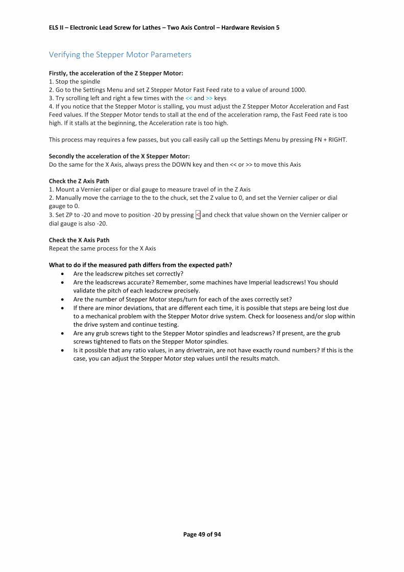
Installed in the case, the whole thing looks like this:
The case is from black anodized alumium, 1.5mm thick.
The LCD screen is protected by a 2mm polycarbonate screen.

ELS II – Electronic Lead Screw for Lathes – Two Axis Control – Hardware Revision 5
Page 14 of 94
Plug & Terminal Assignments USB - USB Type A: Normal USB assignment Delivers power to the ELS II from a 1 Amp USB power supply (1A) and also serves as a connection to a PC for program updates. ZMOT and XMOT Stepper Motor Power Amplifier - RJ45: 1: ENA+ Always 5 Volts 2: ENA- Always 5 Volts 3: PUL STEP (LOW Active) 4: DIR +5 Volts 5: DIR DIRECTION (LOW Active) 6: PUL +5 Volts 7: ERROR LED (HIGH Active) 8: GND Ground (0 Volts) A schematic for directly connecting Stepper Motor Drivers to the ELS II is shown below:

ELS II – Electronic Lead Screw for Lathes – Two Axis Control – Hardware Revision 5
Page 15 of 94
ENC Spindle Encoder Connector - RJ45: 1: A+ 2: A- 3: B- 4: I+ 5: I- 6: B+ 7: 5 Volts 8: GND Ground (0 Volts) The locations of the pins in the jack are shown below:
This connection is used to connect to the encoder on the main spindle to the ELS II. If the encoder is equipped with a ‘Differential Line Driver’ it can be connected directly with a network (‘patch) cable. (See also ‘Encoder Connection’). If no Differential Line Driver is available, you must either connect the encoder to this connector or to the internal encoder connector (X1) as described on the next page.

ELS II – Electronic Lead Screw for Lathes – Two Axis Control – Hardware Revision 5
Page 16 of 94
Internal Connections: X1 These are the pins used for direct connection of the encoder to the ELS II. Pin 1 is at the top, as illustrated in the following image:
1: GND 2: A 3: 5V 4: B If the spindle encoder is connected here, the jumper JP2 must be set to NORMAL as this terminal cannot recognise a differential signal
X2 This is a terminal that may be used for the connection of external buttons. Pin 1 is to the right the top, as illustrated in the following image. The buttons should switch to ground. ‘Make’ pushbuttons are required. The screw terminal is not installed by default.
1: START 2: < 3: > 4: << 5: >> 6: P0 7: Z0 8: X0
9: GND (0 Volts)

ELS II – Electronic Lead Screw for Lathes – Two Axis Control – Hardware Revision 5
Page 17 of 94
System Connection Overview
A complete system consists of
- 1 ELS II Controller - 1 5V USB power adapter - 1 Spindle encoder with differential line driver - 2 Stepper drivers - 2 Stepper motors - 1 Power source
The ELS controller is powered by a 5 Volt USB power supply. The encoder and Stepper Motor input stages are connected via patch cables Power for the stepper motors is delivered by a power supply. The Stepper Motors are connected to the Stepper Motor Driver.
The following pages show how each part is connected.
Encoder with driver ELS II controller
5V USB adapter
Power source

ELS II – Electronic Lead Screw for Lathes – Two Axis Control – Hardware Revision 5
Page 18 of 94
The Spindle Encoder The encoder supplies the exact position of the spindle to the ELS II and, as mentioned previously. 400 pulses per revolution is the optimal signal rate for the ELS II. These signals can be susceptible to interference, especially where frequency inverters have been used, so it advisable to transmit the signals ‘differentially’, whereby the signals are transmitted in opposite directions. To get obtain a differential signal, there is a small converter (a ‘Differential Line Driver’) which is soldered directly to the HEDS or AMT encoder. The converter may then connected to the ELS II via a commercially available network (‘patch’) cable and you will benefit from a well-shielded cable without having to strip or solder anything.
Connecting the Differential Line Driver to a HEDS 5540 Encoder The driver should be connected to the encoder by attaching and soldering the driver as shown in the following images:
Connecting the Differential Line Driver to an AMT103-V Encoder The driver should be connected to the encoder by attaching and soldering the driver as shown in the following images:
If a different encoder type is used, you can either cut off the patch cable at one end and connect the wires to the encoder directly, or connect directly to the internal 5-pin terminal (X1) with your own cable. Do not forget to correctly set the jumper positions, depending upon whether the signal is differential or single ended.

ELS II – Electronic Lead Screw for Lathes – Two Axis Control – Hardware Revision 5
Page 19 of 94
Mounting the Encoder ATTENTION: NEVER REMOVE THE INSTALLED HEX KEY ON THE “HEDS”-type ENCODER BEFORE INSTALLATION! YOU WILL NOT BE ABLE TO REPLACE IT! The encoder can be mounted as follows: To install the encoder you will need to make a mount for the encoder fitted with bearings and a shaft that can drive the encoder from the spindle using a toothed belt. The mount might consist of a piece of round aluminium that has been bored to accept the shaft and bearings. An example of such an arrangement is shown below and further details may be found on https://www.rocketronics.de/downloads/els-download/
With the HEDS encoder, you will also need to make a small centering tool, which must be used to ensure that the encoder is precisely centered, whereas, with the AMT103-V encoder, the centering aid is included in the kit of parts. Such a centering tool is easily made by machining a round piece, with an outside diameter of 11.10 mm and an internal bore of 6.35 mm. The encoder shaft has a diameter of 6.35mm and the hole in the Mounting plate has a diameter of 11.10 mm, so you can use the tool to ensure that the housing is precisely centered on the axis. Please refer to the relevant data sheets, where the assembly of the units are described in greater detail. So, to summarise, the AMT103-V is easier to mount and also has many adaptors for a range of shaft sizes included in the kit of parts. And, best of all, you can select different pulse rates (set the rate to 400 for optimal operation with the ELS II). The HEDS is usually supplied as a ‘standalone’ unit and, because it only fits only one shaft diameter, it is more difficult to install.

ELS II – Electronic Lead Screw for Lathes – Two Axis Control – Hardware Revision 5
Page 20 of 94
The Stepper motors In order to be able to move the leadscrew of the Z-Axis and the screw of the X-Axis you need to attach two
stepper or servo motors.
Stepper motors are special motors which are able to drive one rotation in 200 steps. These motors are driven
by stepper drivers, which convert the steering signals to current signals strong enough to drive the motor.
Servomotors are a bit different, there are many types, all in common is that they have some
kind of position feedback, which allows the driver to steer the position of the motor. Servos
have much higher speed as steppers, but are way more expensive. As we do not need high
speed here, there is seldom a need for servos with the ELS. Also, they often need more than
800 steps/rev to function, which is not possible with the ELS.
There is a middle way, as often: Hybrid Servos, which are stepper motors with a position feedback, so called
“close-loop-steppers”. These offer higher torque numbers, and they are position driven, so they do not loos
steps, which is very good for the ELS. I recommend Hybrid servos, but they are expensive too.
The ELS controller provides step and direction signals for these drivers. One step impulse drives the motor
1/200 rotation further, the direction signal signals in which direction the motor rotates. This way, the ELS can
control the exact position of the motor. Once connected to a leadscrew, the ELS controls exactly how your
leadscrew moves, and therefore steers your carriage of the lathe.
Ordinary steppers do 200 full steps per revolution. However, the drivers are able to divide single steps into
smaller pieces, so called microsteps. That starts by half steps and goes on to very small pieces of one full step.
The smaller you make the microsteps, the smoother the motor runs, with a side effect, that you lose more
torque the smaller you make the steps. Also, the precision of the motor does not get higher with microsteps.
With the ELS, we best use ½ steps or ¼ steps, which result in needing 400 or 800 step impulses per revolution
of the motor.
Coil connection Stepper motors have two or four coils which can be connected to the driver in different ways. Most
stepper motors come with 8 leads, which connect to 4 coils. These coils can be used in series or
parallel. One way to connect is unipolar, which is quite seldom, as most drivers only support bipolar
serial or parallel connection:
There are several advantages to one or the other way, one can write books about this topic, so I
make it easy: We should connect the motors in Bipolar Parallel fashion, as this allows for the highest
torque and speed. We need more voltage and current for that, that is the disadvantage, but we can
overcome that with readily available power-sources with 48V or higher.

ELS II – Electronic Lead Screw for Lathes – Two Axis Control – Hardware Revision 5
Page 21 of 94
Selecting an appropriate Stepper Motor The Stepper Motor must provide enough torque to turn the lead screw in all positions. The amount of torque that is required will depend upon your machine. For normal hobby machines - with a 400-600mm distance between centres dimension - a 3 to 4 Amp NEMA 23 Stepper Motor will be more than adequate. Obviously, larger machines may need more power. It should be noted that taking a small motor and connecting it using a reduction system, it is not advisable, as this will lead to operation that is too slow. This because the ELS II can only deliver a finite clock rate which is directly linked to the number of pulses that are delivered by the spindle encoder. The recommended pulse rate of 400 per revolution, for the encoder, and the recommended step rate of 400 steps per revolution, for the Stepper Motors, are deliberately chosen to ensure proper functioning up to a spindle speed of 3000 rpm and strong diversions from these parameters may result in malfunctions. However, if you must use a reduction system, you should select an encoder that delivers more than 400 pulses per revolution (the AMT103-V, for example, which allows you to set the pulse rate) or, alternatively, set the step rate for the Stepper Motor to full-step (200 steps per revolution). It should be pointed out that the maximum feed rate, in mm per revolution, is directly linked to the number of encoder pulses, per revolution, Stepper Motor steps, per revolution, and the feed of the lead screw. So the maximum feed rate may be calculated as follows: Fmax = 2 x encoder pulses per revolution x leadscrew pitch
motor steps per revolution. So, for example, using the following parameters: Encoder Pulses per Revolution: 400 Stepper Motor Steps per Revolutions: 400 Lead screw pitch: 4mm Fmax = (2 x 400 x 4)/400 = 3200/400=8mm/U So you can see that, if you introduce a reduction of 1: 2, you also halve the maximum feed rate (Fmax). This can be compensated for by increasing the encoder pulses (to, say, 800) or just halving the number of Stepper Motor steps (to, say, full step). But, unfortunately, this cannot be done arbitrarily since at high spindle speeds, too many pulses may be received by the ELS II, which may be overloaded and unable to properly process the signals. This said, if spindle speeds of no more than 1500 rpm are envisaged, the ELS II should be able to process a pulse rate of 800.
A Final Word Concerning Step Rates Wherever possible, the Stepper Motors should be operated at 400 steps per revolution, as higher step rates reduce the maximum feed rates that are possible (see above). We would, therefore, strongly recommend the use of digital Leadshine power amplifiers which will run very smoothly at 400 steps per revolution.

ELS II – Electronic Lead Screw for Lathes – Two Axis Control – Hardware Revision 5
Page 22 of 94
Stepper drivers
To convert the low voltage TTL-Signals from the ELS to motor power, we need stepper drivers. These
are small electronic devices, which create the proper signals and control the motor current of the
stepper motors.
Most types have a step/dir input, 4 output terminals for the stepper motor and a +VDC and GND
connector for power. Very common and the first affordable drivers are from a Chinese company
named Leadshine. They make many kinds of drivers, some of them very suitable for smaller motors.
The driver allows for microstepping of a stepper motor and also
has a way to control the maximum current which flows through
the motor coils. There are digital and analogue drivers from
Leadshine, the latter are older, have the same precision, but run a
bit rougher, as the digital drivers have sophisticated signal
processing leading to a smoother run with higher torque. We
therefore recommend the digital driver, the DM556 is the
workhorse for all motors up to 4.2A current.
Leadshine drivers are very often copied by other Chinese
companies, you find many good and bad copies on ebay and
Alibaba & co. They are all inferior to the original, so beware! Some
of the clones have different connections and are incompatible to the driver adapters. Often they do
not withstand the motor current and overheat.

ELS II – Electronic Lead Screw for Lathes – Two Axis Control – Hardware Revision 5
Page 23 of 94
Setting up the drivers
Every stepper driver allows for setting the microsteps and maximum motor-current to get the most
out of your motor without overload. This is very important, so setup is mandatory.
Setting up the motor-current Leadshine steppers have a several dip-switches to do this. A table with all settings is printed on the
stepper casing. There are two columns there, “Peak current” and “RMS”.
You should set the current according to the RMS-Column. Read the motor datasheet for details
about the maximum allowed current. For example this datasheet:
It shows 4.2A current in bipolar parallel mode. Looking on the driver current settings table we find
4.0A RMS in the last row, which results in Switches 1, 2 and 3 all must set to “ON”:
So in this case, we need to switch the switches 1, 2 & 3all
down to “ON”

ELS II – Electronic Lead Screw for Lathes – Two Axis Control – Hardware Revision 5
Page 24 of 94
Setting up the microsteps
As stated above, all stepper drivers can divide the full steps needed for a full rotation into several
smaller steps, called microsteps. We recommend setting the drivers to a conservative half step, so
we need 400 steps / revolution.
The Leadshine drivers have a table printed on the case telling us how we must set dip switched 5, 6,
7 and 8 to get the correct number of steps. For 400 we need to set the switches OFF-ON-ON-ON.
In some cases you can set the steps to 800, for example if you do not need high feed rates on the Z-
Axis. Also, the X-Axis can be set to 800.
Leadshine Auto-Tune feature An often not seen feature of the digital Leadshine drivers is a very handy autotune feature, which
tunes the driver controller to the connected motor. This only works if the motor is connected and
the power is on.
To activate the autotune cycle simply switch dip switch no. 4 to ON and to OFF again in 1 second.
You may then hear the motor make a few noises, afterwards you will see that it runs smoother than
before.

ELS II – Electronic Lead Screw for Lathes – Two Axis Control – Hardware Revision 5
Page 25 of 94
Connection of the Stepper driver to the ELS The Stepper Motor Drivers are connected to the ZMOT and XMOT jacks on the ELS II. If you are using Leadshine Drivers, you will need a small adapter to allow easy and reliable connection via an ordinary Ethernet-Patchcable. These adapters may be purchased from our shop at www.rocketronics.de/shop But, you should be aware that Leadshine Drivers are available in both analogue and digital forms and you should be sure to select the correct adaptor:
Adapter for analogue Leadshine Drivers:
Adapter for digital Leadshine Drivers
(Photos: Sorotec.de) Connection of the Driver via a patch cable

ELS II – Electronic Lead Screw for Lathes – Two Axis Control – Hardware Revision 5
Page 26 of 94
Connection of the Stepper inputs without an Adapter If an alternative Stepper Motor Driver is being used, you will need take a patch cable and cut a plug off at one end, leaving you 8 exposed wires which you can used to make the connection with the ELS II. Please note the maximum 5 Volt signal level of the ELS. Higher signal voltages will destroy the ELS II! Again, we recommend operating at half step or quad step (i.e. 400 or 800 steps per revolution) The ELS II provides output pulses at + 5V directly to the Driver input. A schematic showing direct connection of a Driver to the ELS II is shown below:

ELS II – Electronic Lead Screw for Lathes – Two Axis Control – Hardware Revision 5
Page 27 of 94
Isolating the Stepper Driver using a Switch If you wish to add flexibility and be able to operate your lathe both manually and with Stepper Motors, you will need to de-energise the Stepper Motor. To do so, you will need to ground the ENA- wire. To achieve this, you must disconnect the patch cable when using the connection adapter interrupt pin number 2 and connect it to pin number 8 using a switch. In this way, the motor is readily de-energised and may be turned my hand.
A schematic showing the direct connection means achieving this is shown below: Without adapter you can connect it like this:

ELS II – Electronic Lead Screw for Lathes – Two Axis Control – Hardware Revision 5
Page 28 of 94
Connection of Stepper drivers and Stepper Motors

ELS II – Electronic Lead Screw for Lathes – Two Axis Control – Hardware Revision 5
Page 29 of 94
Operation Basics The ELS II, may be used is control one or two axes. If there is only one active axis, the Z Axis is operated. If there are two active axes, both the Z and the X axes are operated. Important: If the X Axis is not driven, this must be specified in Settings as described, later, in ‘Settings’. The ELS II’s various modes offer many possibilities and you may still, of course, move the axes manually. Because there are only a finite number of input buttons available, there are several key combinations that you can use. The Rotary Switch is used for all data entries, so you use this switch to set required values. The Rotary Switch also has a down position and, by pressing this button down, you can set values in smaller steps. Glossary of Terms Mode: There are different modes of operation available, such as Turning, Facing, etc. Feed: The feed per revolution of the lathe spindle (in mm per revolution) End Position: The position to which an axis should travel and stop Axis Position: Current position of an axis Rotary Switch: The rotary switch on the control panel of the ELS II Encoder Key The rotary switch has an up and down position Spindle Encoder: The incremental encoder on the lathe spindle Z Axis: The longitudinal axis of the machine X Axis: The transverse axis of the machine Axis Orientation: Z Axis: Towards the spindle is – (minus). Away from the spindle is + (plus).
X Axis: Into the material is always - (minus) In other words, when turning, -X is away from the operator. When boring, -X is towards the operator.

ELS II – Electronic Lead Screw for Lathes – Two Axis Control – Hardware Revision 5
Page 30 of 94
LCD Display The 20x4 LCD display is used to display all of the parameters:
Input Focus Arrow What is Displayed Line 1: The mode that has been selected Line 2: Left: F = The feed rate that has been set in mm
Right: U = The current spindle speed Line 3: Left: ZP = The end position for the Z Axis in mm
Right: The current position of the Z Axis in mm Line 4: Left: XP = The end position for the X Axis in mm
Right: The current position of the X Axis in mm The small arrow on the left indicates the Input Focus. The feed (F) and end positions (ZP and XP) can be adjusted in each mode.

ELS II – Electronic Lead Screw for Lathes – Two Axis Control – Hardware Revision 5
Page 31 of 94
Controls / Buttons
Left or Right These are used to select the required mode of operation. Up or Down These are used to move the input focus arrow, so you may navigate to the setting that you wish to change, using the Rotary Switch. In the Settings mode, you use these buttons to scroll through the Settings menu. Rotary Switch Values can be altered using the Rotary Switch. The Input Focus Arrow indicates the value that is to be altered by use of the Rotary Switch. In operating modes, this allows you to alter the feed rate and the end positions of the Z and X axes. Important: In addition to rotation, the Rotary Switch also has a down position.
In the up position (not pressed down) turning the knob alters the feed rate value in 0.1mm steps.
If pressed down this value is altered in 0.01mm steps
Additionally, if you also press the LEFT/FN button, and rotate the knob, the values are changed in 0.001mm steps
Similarly, the ZP and ZP values may be altered as follows:
In the up position turning the knob alters the position value in 1.0mm steps.
In the down position this value is altered in 0.1mm steps
Additionally, if you also press the LEFT/FN button, and rotate the knob, the values are changed in 0.01mm steps
UP
LEFT/FN RIGHT
UP
DOWN/X-Axis
UP
Rotary switch
UP
START < > << >> P0 Z0 X0
INPUT FOCUS

ELS II – Electronic Lead Screw for Lathes – Two Axis Control – Hardware Revision 5
Page 32 of 94
START This button starts the operations when the spindle is running. < This button stops operations while the spindle is running. When the spindle is stationary, this button is also used to move the Z Axis slowly to the left. If the Down button is also pressed, it moves the X Axis slowly. > This button stops operations while the spindle is running. When the spindle is stationary, this button is also used to move the Z Axis slowly to the right. If the Down button is also pressed, it moves the X Axis slowly. P0: This button sets the selected end value to zero. If P is greater than zero, the carriage movement ceases at that position in all modes. If P is equal to zero, the carriage does not stop automatically, and you will have to decide for yourself when to stop. Z0: Sets the Z Axis position to 0.00. For example, if the turning tool is in contact with the workpiece and you want set that position as a Z0 position, you can use this button to do so. X0: Sets the X Axis position to 0.00. For example, if the turning tool is in contact with the workpiece and you want set that position as an X0 position, you can use this button to do so. The functions of the <> << and >> buttons are described over the following pages. LEFT/FN

ELS II – Electronic Lead Screw for Lathes – Two Axis Control – Hardware Revision 5
Page 33 of 94
The left button has a dual purpose and can command certain functions when used in conjunction with other buttons, as follows: FN plus Up System Reset (used for software updates) FN plus Right Switch to the Settings mode FN plus < S1: Selects the first of four stored feed rates FN plus > S2: Selects the second of four stored feed rates FN plus << S3: Selects the third of four stored feed rates FN plus >> S4: Selects the fourth of four stored feed rates The last four are a convenient way to store frequently used feed values and to retrieve them easily, so you can, for example, set feed values for roughing and finishing passes. Pressing the FN button and one of the 4 directional buttons causes the LCD to display the list of feed rates. If you are viewing this mode, you may alter these values using the Rotary Switch. These values are stored even after switching off. Important: If you have changed a feed value, using the Rotary Switch, it will not be automatically applied as current feed rate. Only if you press the FN button and one of the direction buttons, without operating the Rotary Switch, will the selected value be adopted.
Shown above is the S list display. The selected value is indented.

ELS II – Electronic Lead Screw for Lathes – Two Axis Control – Hardware Revision 5
Page 34 of 94
Basic Button Functions at a Glance:
Starting & Stopping Functions Whilst the Spindle is Turning
Please Note: ABORT terminates all processes. Wherever possible, you should keep the spindle rotating until the cancellation process is completed.
Changing Operating Mode & Switching to Settings
Scrolling Through the Settings
START/STOP or START/ABORT
ABORT and Return to Rest
LEFT or RIGHT - Change the Mode
LEFT and RIGHT - Switch to Settings
UP and DOWN - Scroll Through the Settings
ELS II – Electronic Lead Screw for Lathes – Two Axis Control – Hardware Revision 5
Page 35 of 94
Moving the Z Axis The Z Axis can be moved slowly, quickly and in steps (‘Jogged’) using these buttons.
The < and > buttons move the carriage slowly. The << and >> buttons move it quickly.
Please Note: During a running operation <or > aborts the operation.
Jogging the Z Axis is achieved by pressing the UP button while turning the Rotary Switch. With the Rotary
Switch in the ‘up’ position, the steps are made to the value of Step 1, in Settings (usually 0.1mm). With the Rotary Switch in the ‘down’ position, they are made to the smaller (Step 2) setting.
Manual Movement – Z Axis (Fast and Slow)
Jogging – Z Axis (Step 1 and Step 2)

ELS II – Electronic Lead Screw for Lathes – Two Axis Control – Hardware Revision 5
Page 36 of 94
Moving the X Axis The X Axis can be moved slowly, quickly and in steps (‘Jogged’) using these buttons in conjunction with the
DOWN button.
The < and > buttons move the carriage slowly. The << and >> buttons move it quickly. Left (< or << ) moves
the crosslide away from the operator. Right (> or >> ) moves the crosslide towards the operator.
Jogging the X Axis is achieved by pressing the DOWN button while turning the Rotary Switch. With the Rotary
Switch in the ‘up’ position, the steps are made to the value of Step 1, in Settings (usually 0.1mm). With the Rotary Switch in the ‘down’ position, they are made to the smaller (Step 2) setting.
Manual Movement – X Axis (Fast and Slow)
Jogging – X Axis (Step 1 and Step 2)

ELS II – Electronic Lead Screw for Lathes – Two Axis Control – Hardware Revision 5
Page 37 of 94
Changing Parameter Values The feed rate, the end position for the Z Axis (ZP) and the end position for the X Axis (XP) may be altered using
these buttons. To achieve this, use the UP and DOWN keys to move the Input Focus Arrow to one of the
three lines and then alter the required value with the Rotary Switch.
The Input Focus Arrow (the double chevron, on the right, ringed in red in the image above) indicates which value will be changed by the Rotary Switch.
UP or DOWN – Moves the Input Focus Arrow
The Rotary Switch - Is Used to Alter the Selected Value

ELS II – Electronic Lead Screw for Lathes – Two Axis Control – Hardware Revision 5
Page 38 of 94
Zeroing of Values (With Spindle either in Motion or Stationary)
With the P0 button, you may zero the selected parameter – this may be either
Feed Rate (F), Z Position (ZP) or X Position (XP).
The Input Focus Arrow indicates which value is to be altered with P0.
This arrow is moved using the UP and DOWN buttons.
Z0 sets the current axis position of the Z Axis to zero.
X0 sets the current axis position of the X Axis to zero.
P0, Z0 and X0 set values to 0

ELS II – Electronic Lead Screw for Lathes – Two Axis Control – Hardware Revision 5
Page 39 of 94
Quick Access to Feed Values
By pressing the FN button in conjunction with one of the direction < > << or >> buttons a menu with feed
values can be called up. There values can be selected in quick access, such as commonly used thread pitches. The 4 values are stored individually for each mode.
The last four are a convenient way to store frequently used feed values and to retrieve them easily, so you can, for example, set feed values for roughing and finishing passes. Pressing the FN button and one of the 4 directional buttons causes the LCD to display the list of feed rates.
FN plus < S1: Selects the first of four stored feed rates
FN plus > S2: Selects the second of four stored feed rates
FN plus << S3: Selects the third of four stored feed rates
FN plus >> S4: Selects the fourth of four stored feed rates
If you are viewing this mode, you may alter these values using the Rotary Switch. These values are stored even after switching off. Important: If you have changed a feed value, using the Rotary Switch, it will not be automatically applied as
current feed rate. Only if you press the FN button and one of the direction buttons, without operating the
Rotary Switch, will the selected value be adopted.
Shown above is the S list display. The selected value is indented.

ELS II – Electronic Lead Screw for Lathes – Two Axis Control – Hardware Revision 5
Page 40 of 94
Movement of the Axes by Hand As described above, the ELS II can be used to move the Z and X axes manually.
The < > << or >> buttons and the Rotary Switch with its up/down position serve this purpose.
To remind you:
Use the arrow keys < > << or >> to move the Z Axis slowly and quickly
Pressing the UP button and turning the Rotary Switch moves the Z Axis step by step
Pressing the DOWN button in conjunction with the < > << or >> moves the X Axis slowly and
quickly
Pressing the DOWN button and turning the Rotary Switch moves the X Axis step by step
An exception is < and > both of which - if the spindle is turning and an operation is in progress - abort the
operation.
The Procedure for Exact Positioning The ELS II has some inherently useful movement methods: For example, a manual movement in the minus Z or minus X direction always stops the tool at the prescribed end position and at zero. Pressing the movement command, again, moves the tool again. If you want to return to a prescribed position then you must always drive to the right, beyond the position, and then drive back to the position, from the left, where the carriage will stop again. Please note that, when moving towards plus Z and plus X you should not stop the movement before actually reaching a plus position. You must always approach a minus position from a plus position to achieve an automatic halt of the tool. This is to ensure that backlash is compensated for and that any minus position is accurate. In this way you can achieve fast and precise movements. For example, if - having made a cut and with the tool returned to the stop position – you want to travel to zero for another operation, you can go to the zero position at the push of a button. And you can also approach precise positions, you turn to the end position of the axle piece by piece and keep driving, in the same direction, until you are at the desired location. Restriction: The ELS II does not yet support stop at zero or at end positions for internal turning operations. This feature is still under development. In the meantime, you can switch to an alternative mode and move to those positions using that mode. Please note, however, that in internal turning modes, the polarity of the X Axis is reversed. In other words - (minus) is towards the operator + (plus) is away from the operator. In other words, the opposite to external turning modes.
This is easy to remember: Minus is always towards the surface of the workpiece that you wish to machine.

ELS II – Electronic Lead Screw for Lathes – Two Axis Control – Hardware Revision 5
Page 41 of 94
Commissioning
To commission the unit, the Stepper Motor for driving the Z Axis must be powered and connected to the Electronic Lead Screw, via the patch cable, to the ZMOT socket.
If the X Axis is also to be controlled, the Stepper Motor for the X Axis must also be powered and connected to the Electronic Lead Screw, via the patch cable, to the MOTX socket.
Then the Spindle Encoder should be connected to the Electronic Lead Screw, via the patch cable, to the ENC socket.
Then connect the USB Power Adapter to the USB port. Having followed the instructions above, you should switch on the Electronic Lead Screw which will display the following message on the LCD Screen:
ELS II DUAL AXIS (c) LOUIS SCHREYER VERSION 353-rev 5
After one second, the message will change to the Default Display, as follows.
VERY IMPORTANT: ALL OF THE BASIC PARAMETERS, DESCRIBED IN “SETTINGS”, MUST BE SET PRIOR TO OPERATION.

ELS II – Electronic Lead Screw for Lathes – Two Axis Control – Hardware Revision 5
Page 42 of 94
Settings
To enter the Settings Mode, press both the LEFT/FN + RIGHT buttons simultaneously. The display will
change to the Settings Mode, like this:
In the Settings Mode, values may be changed using the Rotary Switch on the control panel. Turning it clockwise increases the value of a parameter. Turning it counter-clockwise decreases the value of a parameter
Use the UP and DOWN keys to move from one entry to the next.
The following describes the Settings Menu:
WAITING PERIOD: (One Axis Operation Only) This is length of time you wish the Z Axis to pause before returning to 0 having reached the end of an automatic operation. This is the time that is available for you to withdraw the cutting tool from the workpiece, manually, so as to avoid destroying the thread that you are cutting. We recommend 1000-2000 ms. If you need longer than this, you may increase this value. In 2-Axis operation this setting is irrelevant as the cross-slide is automatically withdrawn.
MODE LOCK DURING SPINDLE ROTATION: With this parameter set to ‘ON’ you cannot change an Operating Mode (ie from ‘Turning’ to ‘Boring’) when the spindle is rotating. With this set to ‘OFF’ such a change is allowed. It is HIGHLY RECOMMENDED that this parameter be set to ‘ON’ thus avoiding accidental switching which might have dangerous consequences.
START MODE AT SYSTEM START: The mode to be displayed when starting the controller
LENGTH OF STEP IMPULSE (IN μs) The duration of the pulses sent to the Stepper Motor output stage. Normally 4μs are enough. If necessary 8 and 12 μs are also possible.
SPINDLE ENCODER IMPULSE/U: This is the number of pulses the spindle encoder delivers per revolution. It is strongly recommended that you choose an encoder with 400 pulses per revolution. The type HEDS 5540 H06 delivers 400 pulses/U. The DR type AMT103 is adjustable. Please set this to 400. Higher resolutions are possible, but I recommend staying with 400 as at high speeds, the ELS II can be overloaded. For example, at 3000 RPM and 400 pulses, the ELS II must already process 40,000 responses per second - each pulse of the encoder being read internally as 2 pulses because the ELS II reads every rising edge of the signal. So, internally, 800 pulses are created by 400 pulses so it makes little sense to use more. ATTENTION: Changes to the spindle encoder pulses in the Settings Menu are only accepted following a restart of the controller!
SPINDLE ENCODER

ELS II – Electronic Lead Screw for Lathes – Two Axis Control – Hardware Revision 5
Page 43 of 94
REVERSE DIRECTION: Reverses the direction indicated by the encoder.
Settings for the Stepper Motor on the Z Axis
Z-STEPPER MOTOR PULSE DOUBLING: With this setting, the number of step pulses can be doubled. This may be useful in some cases when the Stepper Motor Driver requires more than 800 steps/revolution - Beast and Triple Beast Drive Boards for example. The Stepper Motors may not operate so smoothly, so you have to experiment to establish the best solution.
Z-STEPPER MOTOR SPINDLE FEED RATE: This is the feed rate of the machine’s Z Axis lead screw. Most feed rates are in the range of 2-4 mm, but there are also inch and custom leadscrews and/or feed rates that are not precise. Where there is doubt concerning this parameter (ie if the displayed distance travelled value differs from the actual distance travelled) you must measure the feed rate and adjust this value until the travelled distance in the display matches reality. To achieve this, drive a path 100 mm in length and measure the actual distance travelled with a Vernier caliper. In this way, you can establish an exact value step by step.
Z-STEPPER MOTOR BACKLASH COMPENSATION: This is the backlash on the Z Axis which – unless it is fitted with a precise ball screw - will almost certainly have some backlash. The controller can compensates for this, so it is advisable to measure the backlash and set it here. It is possible to set larger than actual backlash figures, without diminishing accuracy, but you must not set smaller than actual figures, as this would result in to inaccuracies.
Z-STEPPER MOTOR STEPS/U: This is the number of steps that the Stepper Motor takes to drive the lead screw one full turn. Stepper Motors typically use 200 steps per revolution and switching the Stepper Motor Driver to Half Step increases this to 400 steps. Half-step is typically enough and you should not overdo the number of steps per revolution. For example, with a spindle feed of 4mm and Half Step operation of the Stepper Motor, one step results in a resolution of 4mm/400 = 0.01mm. Note: The maximum achievable feed depends directly on this value. At 800 steps, the maximum feed is halved, so you should think twice about using more than 400 steps. See also ‘Selection of an Appropriate Stepper Motor’
Z-STEPPER MOTOR ACCELERATION: The acceleration of the Stepper Motor in mm/s2. This value cannot be calculated but must be determined by experiment. Stepper Motors cannot be immediately switched from 0 to 100 as they would inevitably lock up. The Electronic Lead Screw therefore commands all movements with an adjustable acceleration ramp. Values between 100 and 150 should be tried at the beginning.
Z-STEPPER MOTOR SLOW FEED:

ELS II – Electronic Lead Screw for Lathes – Two Axis Control – Hardware Revision 5
Page 44 of 94
The slow feed rate in mm/min. This is used when the Z Axis is approaching material in an automatic operation or when pressing < and >
Z-STEPPER MOTOR FAST FEED: The fast feed rate in mm/min. This is used when the Z Axis is retracted in automatic operations and when you press << and >> Maximum possible is 4800 mm/min.
Z-STEPPER MOTOR REVERSE: If the Z Motor turns in the wrong direction, the direction of rotation can be reversed here.
Settings for the Stepper Motor on the X Axis
X-STEPPER MOTOR MOTOR AVAILABLE: If a Stepper Motor is present and should be used, the value here should be ‘YES’. If this parameter is set to ‘NO’ the Axis will not be used and Automatic Modes such as internal turning, internal threading, facing and parting will not be available. Also, there will be no automatic advance or withdrawal in the X Axis. After returning from the Settings Menu, the control will restart when changing this setting!
X-STEPPER MOTOR SPINDLE FEED: This is the feed rate of the machine’s X Axis lead screw. Most feed rates are in the range of 2-4 mm, but there are also inch and custom leadscrews and/or feed rates that are not precise. Where there is doubt concerning this parameter (ie if the displayed distance travelled value differs from the actual distance travelled) you must measure the feed rate and adjust this value until the travelled distance in the display matches reality. To achieve this, drive a path 100 mm in length and measure the actual distance travelled with a Vernier caliper. In this way, you can establish an exact value step by step.
X-STEPPER MOTOR BACKLASH COMPENSATION: This is the backlash on the X Axis which – unless it is fitted with a precise ball screw - will almost certainly have some backlash. The controller can compensate for this, so it is advisable to measure the backlash and set it here. It is possible to set larger than actual backlash figures, without diminishing accuracy, but you must not set smaller than actual figures, as this would result in inaccuracies.
X-STEPPER MOTOR STEPS/U: This is the number of steps that the Stepper Motor takes to drive the lead screw one full turn. Stepper Motors typically use 200 steps per revolution and switching the Stepper Motor Driver to Half Step increases this to 400 steps. Half-step is typically enough and you should not overdo the number of steps per revolution. However, on the X Axis you can, if you wish, take more than 400 steps. 800 or 1000 steps are not a problem.
X-STEPPER MOTOR ACCELERATION: The acceleration of the Stepper Motor in mm/s2. This value can’t be calculated but must be determined by trial and error. Values between 100 and 150 should be tried at the beginning.
X-STEPPER MOTOR

ELS II – Electronic Lead Screw for Lathes – Two Axis Control – Hardware Revision 5
Page 45 of 94
SLOW FEED: The slow feed rate in mm/min. This is used when approaching the workpiece in the X Axis in automatic operation and when DOWN and < or > are pressed.
X-STEPPER MOTOR FAST FEED: The fast feed rate in mm/min. This is used when the X Axis is retracting from an automatic operations and when DOWN and << or >> are pressed. The maximum possible feed rate is 4800 mm/min
X-STEPPER MOTOR REVERSE: If the X Stepper Motor rotates in the wrong direction, the direction of rotation can be reversed.
Further Settings
X + Z-STEPPER MOTOR STEP 1: The increment in mm that should be used for large incremental feeds when turning the Rotary Switch on the control panel. Usually 0.1mm. To adjust the Z Axis parameter the Rotary Switch should rotated in the UP position. To adjust the X Axis parameter the Rotary Switch should rotated in the DOWN position.
X + Z-STEPPER MOTOR STEP 2: The increment in mm that should be used for small incremental feeds when turning the Rotary Switch on the control panel. Usually 0.01mm. To adjust the Z Axis parameter the Rotary Switch should rotated in the UP position. To adjust the X Axis parameter the Rotary Switch should rotated in the DOWN position.
DEPTH OF CUT Z AP LIGHT: In automatic operations, cutting is always done in two stages: Several roughing cuts and a finishing cut. The depth of the finishing cut for the Z Axis is set here (in mm).
DEPTH OF CUT Z AP ROUGH: In automatic operations, cutting is always done in two stages: Several roughing cuts and a finishing cut. The depth of each roughing cut for the Z Axis is set here (in mm). (NOTE: Before each automatic pass, the controller will display the scheduled cutting values, using these two values, but you can easily adjust the values with the Rotary Switch before starting the process).
DEPTH OF CUT X AP LIGHT: The depth of the finishing cut in the X Axis is set here (in mm).
DEPTH OF CUT X AP ROUGH: The depth of each roughing cut for the X Axis is set here (in mm).
REST POSITION Z REST POSITION: The Resting Position of the tool in the Z Axis – or the point to which the tool will always return at the end of an operation. If you want the Z Axis to end up with exactly 0.00 then you should enter 0 here.

ELS II – Electronic Lead Screw for Lathes – Two Axis Control – Hardware Revision 5
Page 46 of 94
REST POSITION X REST POSITION: As above for the X Axis
TOOL CORNER RADIUS IN MM: The nose radius for the cutting edge of the tool that will be used. For inserts a cutting radius is always defined. This value is used for radii compensation for taper and radius turning.
LANGUAGE The system language, setting allows for German and English language.

ELS II – Electronic Lead Screw for Lathes – Two Axis Control – Hardware Revision 5
Page 47 of 94
Testing the Settings for Optimised Operation Be sure you used the settings to set up the encoder and motor parameters. For a first test you should set acceleration and slow and fast speeds of the motors to low levels.
Correcting the encoder direction
Switch to the “ANGLE”-Mode with the LEFT or RIGHT button
Now use your hand to turn the Chuck counterclockwise. The display should change the angle now, and show an “L” as direction. If this shows an “R” for Right, your encoder is set to the wrong direction. Go to the SETTINGS - SPINDLE ENCODER REVERSE DIRECTION – and change the setting there. Repeat the test, now it should show “L” as direction if you spin the spindle counterclockwise.
Verify the correct Z-Motor wiring
1. Switch to the “GEARBOX L”-Mode with the LEFT or RIGHT button
2. Set the feed rate to 0.5 mm. 3. Press Z0 and P0 to set the Z position and Z end position to 0. 4. Release the saddle half nut so that the carriage does not move when the lead screw is rotated.
Do not insert a turning tool! Do not insert a workpiece! Keep your distance!
5. Start the spindle, as slowly as possible, initially. 6. Press the START button on the Electronic Lead Screw The stepper motor should now turn whenever the spindle is turning. If you change the direction of rotation of the spindle, the Stepper Motor should now turn in the opposite direction. Now engage the saddle half nut. If the spindle turns counter-clockwise, the carriage should move to the left. If it does not, the Stepper Motor is wired the wrong way round, but that is no problem: Go to the SETTINGS – Z STEPPER MOTOR REVERSE – and change the setting there. This reverses the direction of the motor. Repeat the test, the carriage should now move to the left if you drive the spindle counterclockwise.
Also use the < > << and >> keys to drive the Z-Axis manually, it should respond to the correct directions.
If the spindle turns to the counter-clockwise, the carriage should move towards the chuck.

ELS II – Electronic Lead Screw for Lathes – Two Axis Control – Hardware Revision 5
Page 48 of 94
Verify the correct X-Motor wiring
To test the correct direction drive the X-Axis manually by pressing DOWN together with one of the < > <<
and >> keys. (For a reminder the DOWN -Key has an “X” engraved as it is also used to activate the jog keys
for the X-Axis.)
At pressing < or << the X-Axis should move from you away, pressing > or >> the X-Axis should move towards
you. If it runs the other way round you can switch the motor direction to reverse, which is done by going to SETTINGS – X STEPPER MOTOR REVERSE and change the setting there. If these three tests run fine, your system is almost setup correctly. Congratulations, you can now carefully experiment with higher RPM and other feeds and drive your axes as you like.
ELS II – Electronic Lead Screw for Lathes – Two Axis Control – Hardware Revision 5
Page 49 of 94
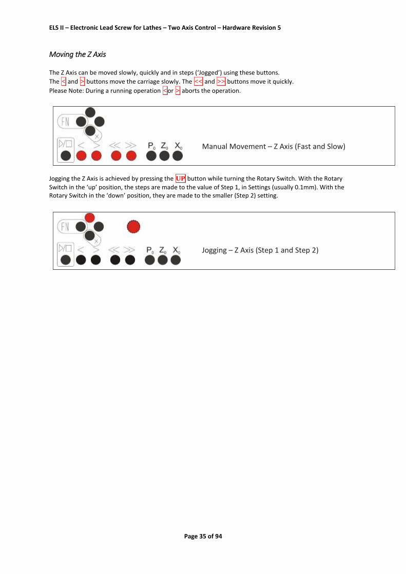
Verifying the Stepper Motor Parameters Firstly, the acceleration of the Z Stepper Motor: 1. Stop the spindle 2. Go to the Settings Menu and set Z Stepper Motor Fast Feed rate to a value of around 1000. 3. Try scrolling left and right a few times with the << and >> keys 4. If you notice that the Stepper Motor is stalling, you must adjust the Z Stepper Motor Acceleration and Fast Feed values. If the Stepper Motor tends to stall at the end of the acceleration ramp, the Fast Feed rate is too high. If it stalls at the beginning, the Acceleration rate is too high. This process may requires a few passes, but you call easily call up the Settings Menu by pressing FN + RIGHT. Secondly the acceleration of the X Stepper Motor: Do the same for the X Axis, always press the DOWN key and then << or >> to move this Axis Check the Z Axis Path 1. Mount a Vernier caliper or dial gauge to measure travel of in the Z Axis 2. Manually move the carriage to the to the chuck, set the Z value to 0, and set the Vernier caliper or dial gauge to 0.
3. Set ZP to -20 and move to position -20 by pressing < and check that value shown on the Vernier caliper or
dial gauge is also -20. Check the X Axis Path Repeat the same process for the X Axis What to do if the measured path differs from the expected path?
Are the leadscrew pitches set correctly?
Are the leadscrews accurate? Remember, some machines have Imperial leadscrews! You should validate the pitch of each leadscrew precisely.
Are the number of Stepper Motor steps/turn for each of the axes correctly set?
If there are minor deviations, that are different each time, it is possible that steps are being lost due to a mechanical problem with the Stepper Motor drive system. Check for looseness and/or slop within the drive system and continue testing.
Are any grub screws tight to the Stepper Motor spindles and leadscrews? If present, are the grub screws tightened to flats on the Stepper Motor spindles.
Is it possible that any ratio values, in any drivetrain, are not have exactly round numbers? If this is the case, you can adjust the Stepper Motor step values until the results match.

ELS II – Electronic Lead Screw for Lathes – Two Axis Control – Hardware Revision 5
Page 50 of 94
Testing the Spindle Encoder The correct operation of the Spindle Encoder may be readily verified as follows: 1. Switch to the Spindle Angle mode 2. Mark a zero point on the lathe chuck and set the angle at the controller to 0. 3. Now allow the lathe spindle run, for a while, at medium speed. 4. Stop the spindle and continue turning the chuck, by hand, in the direction of rotation to the zero point. 5. At this point the value shown on the controller should also display 0. If there is a noticeable difference, then there is an issue with encoder or the encoder Settings. Checklist
Are the number of pulses set correctly (usually 400)?
Is the encoder properly aligned with and connected to the spindle?
Are you using a transmission to drive the encoder? Is it possible the ratio values are not exactly round numbers (ie 1:1.75)?
If you are using a transmission to drive the encoder, could there be any slippage in the system due to loose or worn belts, worn or poorly meshing gears?
In all cases, it is preferable for the Spindle Encoder to be driven 1:1 to the lathe spindle – and the use of gears should be avoided - but, if that is not possible, then simple ratios (eg 1:2, 1:4) should be employed. You can then select the number of impulses at the ELS II unit accordingly. Optimally 400 pulses per revolution will be sent to the controller thereafter. Please Note: The functions of each ELS II unit are checked and verified prior to delivery. It is therefore most unlikely that poor operation is the fault of the unit. In the event of poor operation, it is advisable to carefully check the Settings and, in particular, the connections between the ELS II unit and the Stepper Motors.
But, if you are experiencing any problems please contact us at [email protected]. We would suggest that
you have your Settings written down so you may easily refer to them.

ELS II – Electronic Lead Screw for Lathes – Two Axis Control – Hardware Revision 5
Page 51 of 94
Operating Modes The ELS II offers the following operating modes, which are easily switched using the LEFT and RIGHT keys: In Two-Channel Mode - With an Activated X-Stepper Motor:
Gearbox Left
Gearbox Right
Turning
Boring
Facing
Parting
Ext Thread
Int Thread
Ext Thread <0
Ext Taper
Int Taper
Ext Radius )
Ext Radius (
Int Radius )
Int Radius (
Grinding
Angle
Settings In One-Channel Mode - With a Non-Activated X-Stepper Motor:
Gearbox Left
Gearbox Right
Turning
Ext Thread
Int Thread
Ext Thread <0
Grinding
Angle
Settings [Note that in One-Channel Mode, the operations that require automation of the X Axis are missing].
The following pages provide explanations of each mode. PLEASE NOTE:
All operations are begun by pressing the Start ► button and may be
aborted by pressing one of the Abort (< or >) buttons.

ELS II – Electronic Lead Screw for Lathes – Two Axis Control – Hardware Revision 5
Page 52 of 94
◄ GEARBOX L ► In this mode the Z Axis Stepper Motor is driven at the feed rate that you have set in conjunction with the spindle speed - the spindle, leadscrew and Stepper Motor being synchronised with each other. So that's what you've done before, with change wheels, except now, it’s very much easier. In this mode, if the spindle turns counter-clockwise the carriage moves to the left. If the spindle turns clockwise the carriage moves to the right. If the end position ("Z P") is not equal to 0, the carriage stops at the end position but, internally, the ELS II calculates the position so, when returning the cutting tool still follows the path of the thread. This is something that cannot be achieved with real gears.
Note: After switching to this mode, the feed must first be started with the ► button for safety reasons.
The feed can be stopped and restarted at any time with the ► button.
◄ GEARBOX R ► In this mode, if the spindle turns counter-clockwise the carriage moves to the right. If the spindle turns clockwise the carriage moves to the left.

ELS II – Electronic Lead Screw for Lathes – Two Axis Control – Hardware Revision 5
Page 53 of 94
◄ TURNING ► This mode is used to remove material in the longitudinal direction:
Starting from the zero point, the turning tool moves to –X then to –Z. Here, ZP is the length of the desired cut, in the Z Axis, and XP is the amount material that you wish to remove in the X Axis. ATTENTION: -X is ALWAYS in the material removal direction. In this case, -X is away from the operator. NOTE: Always drive towards the workpiece to zero the X Axis and then set to 0 to ensure that the backlash is taken out. In this mode, there are three possible variants: 1. ZP=0 and XP=0.
In this case, no end points have been specified so when the Start ► button has been pressed and the operation
has been confirmed (by pressing ► again) the tool goes to X0.00 and then in the –Z direction until such time as
the Stop () button is pressed. In this case the operation may be continued by pressing the Start ► button
again. Pressing one of the Abort buttons (< or > ) stops the operation and either returns the tool to the Z0 and
X0 position or to the Resting Position (if the Z and/or X Resting Position parameters are greater than zero). 2. ZP<0 and XP=0 With these parameters, there is only an end position for the Z Axis and no command for removal of material in
the X Axis. Upon pressing the Start (► ) button the tool goes directly to the X0.00 position (without a further
confirmation command) and then drives the tool to the –Z position before withdrawing the tool to X0.20 and Z0.00 and then resetting the X and Z positions to the stop coordinates.
3. ZP<0 and XP<0 Values for the length and depth of the cut are given here, so the operation is carried out automatically in several
passes. After the Start (► ) button is pressed, the ELS II displays an overview of the data for the individual passes.
Having reviewed this data (and made adjustments to the number of passes (if required)) the operation may be
begun by pressing the Start (► ) button again. Pressing one of the Abort buttons ( < or > ) stops the operation
and either returns the tool to the Z0 and X0 position or to the Resting Position (if the Z and/or X Resting Position parameters are greater than zero). IMPORTANT: Always ensure that the Zero points are set correctly.

ELS II – Electronic Lead Screw for Lathes – Two Axis Control – Hardware Revision 5
Page 54 of 94
Turning Example: ZP=-10 and XP=-5. In this example 5mm of material will be removed along a length of 10 mm
After starting the spindle and pressing the Start ► button, the ELS II first calculates the number of passes that
are required based upon the values for roughing and finishing depth cuts that have been defined in Settings. For example, the following image shows what is displayed, for this example operation, when the roughing cut setting is 0.50mm and the finishing cut is set at 0.10mm. In all cases, the maximal value for roughing cuts is never exceeded and the ELS II always remainders the precise value of the finishing cut.
So, to summarise this display: F=0.10 The feed rate in mm/rev. L=10.00 The length of the cut in the Z Axis. ap=5.00 The total depth of cut that is required in the X Axis. nap = 10x 0.49+ 0.10 The number of roughing cuts, the depths of the roughing cuts and the depth
of the final finishing cut. So, in this example, 0.49 mm is removed by each roughing cut and there is a single finishing cut of 0.10mm – giving a total removed material (ap) dimension of 5.00 mm using 11 passes. And Here Is The Trick:
You can increase, or decrease, the number of roughing cuts with the Rotary Switch and the ELS II will
recalculate the depths of cut accordingly! This allows you to quickly change the roughing cut parameters, but you should be sure not to overload the machine, the tool or the material. Having reached the end of the operation, you can also set the number of passes to 1 (without changing the target material removal parameter) to carry out spring passes.
If you are happy with the values that are displayed, begin the operation by press the Start ► button. If you
would like to change the values, press one of the Abort < or > buttons.

ELS II – Electronic Lead Screw for Lathes – Two Axis Control – Hardware Revision 5
Page 55 of 94
◄ BORING ► This mode is used to remove material in the longitudinal direction, but from the inside:
Starting from the zero point, the boring tool moves to –X and then to –Z. ZP corresponds to the length and XP to the depth of the material that is to be removed ATTENTION: -X is ALWAYS in the material removal direction. In this case, -X is towards the operator. NOTE: Always drive towards the operator to zero the X Axis and then set to 0 to ensure that the backlash is taken out. In this mode, there are three possible variants: 1. ZP=0 and XP=0
In this case, no end points have been specified so when the Start (► ) button has been pressed and the operation
has been confirmed (by pressing ► again) the tool goes to X0.00 and then in the –Z direction until such time as
the Stop () button is pressed. In this case the operation may be continued by pressing the Start (► ) button
again. Pressing one of the Abort buttons < or > stops the operation and either returns the tool to the Z0 and
X0 position or to the Resting Position (if the Z and/or X Resting Position parameters are greater than zero). 2. ZP=<> 0 XP=0 With these parameters, there is only an end position for the Z Axis and no command for removal of material in
the X Axis. Upon pressing the Start (► ) button the tool goes directly to the X0.00 position (without a further
confirmation command) and then drives the tool to the –Z position before withdrawing the tool to X0.20 and Z0.00 and then resetting the X and Z positions to the stop coordinates. 3. ZP=<0 and XP=<0 Values for the length and depth of the cut are given here, so the operation is carried out automatically in several
passes. After the Start (► ) button is pressed, the ELS II displays an overview of the data for the
individual passes. Having reviewed this data (and made adjustments to the number of passes (if required)) the operation may be
begun by pressing the Start (► ) button again. Pressing one of the Abort buttons < or > stops the operation
and either returns the tool to the Z0 and X0 position or to the Resting Position (if the Z and/or X Resting Position parameters are greater than zero. IMPORTANT: Always ensure that the Zero points are set correctly.

ELS II – Electronic Lead Screw for Lathes – Two Axis Control – Hardware Revision 5
Page 56 of 94
◄ FACING ► This mode is used for the removal of material on the front of the workpiece.
Starting from the zero point, the turning tool moves to –Z and then to –X. In this mode, ZP corresponds to the amount of material that is to be removed (ap). XP refers to the depth of cut in the X Axis (r). ATTENTION: -X is ALWAYS in the material removal direction. In this case, -X is away from the operator. NOTE: Always drive towards the workpiece to zero the X Axis and then set to 0 to ensure that the backlash is taken out. In this mode, there are three possible variants: 1. ZP=0 and XP=0
In this case, no end points have been specified so when the Start (► ) button has been pressed and the operation
has been confirmed (by pressing ► again) the tool goes to Z0.00 and then in the –X direction until such time as
the Stop () button is pressed. In this case the operation may be continued by pressing the Start (► ) button
again. Pressing one of the Abort buttons < or > stops the operation and either returns the tool to the Z0 and
X0 position or to the Resting Position (if the Z and/or X Resting Position parameters are greater than zero). 2. ZP=0 XP=<0 With these parameters, there is only an end position for the X Axis and no command for removal of material in
the X Axis. Upon pressing the Start (► ) button the tool goes directly to the Z0.00 position (without a further
confirmation command) and then drives the tool to the –X position before withdrawing the tool to X0.20 and Z0.00 and then resetting the X and Z positions to the stop coordinates. 3. ZP=<0 and XP=<0 Values for the length and depth of the cut are given here, so the operation is carried out automatically in
several passes. After the Start (► ) button is pressed, the ELS II displays an overview of the data for the
individual passes. Having reviewed this data (and made adjustments to the number of passes (if required)) the operation may be
begun by pressing the Start (► ) button again. Pressing one of the Abort buttons < or > stops the operation
and either returns the tool to the Z0 and X0 position or to the Resting Position (if the Z and/or X Resting Position parameters are greater than zero.

ELS II – Electronic Lead Screw for Lathes – Two Axis Control – Hardware Revision 5
Page 57 of 94
You can increase, or decrease, the number of roughing cuts with the Rotary Switch, on the control panel, and the ELS II will recalculate the depths of cut accordingly. This allows you to quickly change the roughing cut parameters, but you should be sure not to overload the machine, the tool or the material. IMPORTANT: Always ensure that the Zero points are set correctly.

ELS II – Electronic Lead Screw for Lathes – Two Axis Control – Hardware Revision 5
Page 58 of 94
◄ PARTING ► This mode is used to part off workpieces.
Starting from the zero point, the turning tool moves to –X. In this mode, XP corresponds to the radius of the workpiece. Values in the Z Axis are ignored. ATTENTION: -X is ALWAYS in the material removal direction. In this case, -X is away from the operator. NOTE: Always drive towards the workpiece to zero the X Axis and then set to 0 to ensure that the backlash is taken out. There are two possible variants: 1. XP=0
In this case, no end point has been specified so when the Start (► ) button has been pressed and the operation
has been confirmed (by pressing ► again) the tool travels in the –X direction until such time as the Stop ()
button is pressed. In this case the operation may be continued by pressing the Start (► ) button again. Pressing
one of the Abort buttons < or > stops the operation and either returns the tool to the X0 position or to the
Resting Position (if the X Resting Position parameter is greater than zero). 2. XP=<0 A value for the depth of the cut is specified here, so the operation is carried out automatically.
Upon pressing the Start (► ) button, you are invited to review the cutting plan. Having reviewed this data (and
made adjustments (if required)) the operation may be begun by pressing the Start (► ) button again. Pressing
one of the Abort buttons < or > stops the operation and either returns the tool to the Z0 and X0 position or
to the Resting Position (if the Z and/or X Resting Position parameters are greater than zero). . PLEASE NOTE: Values for Z Axis are ignored and the Z Axis is not moved in this mode.

ELS II – Electronic Lead Screw for Lathes – Two Axis Control – Hardware Revision 5
Page 59 of 94

ELS II – Electronic Lead Screw for Lathes – Two Axis Control – Hardware Revision 5
Page 60 of 94
◄ EXTERNAL THREADING ► (1 Axis: ◄ THREADING ►) This mode is for automatically turning threads. This mode moves beyond 0 when resetting in the +Z direction.
Starting from the zero point, the turning tool moves to -X then to –Z. In this mode, ZP corresponds to the length of the required thread. XP refers to the depth of the thread (ap) and F is the pitch of the required thread. ATTENTION: -X is ALWAYS in the material removal direction. In this case, -X is away from the operator. NOTE: Always drive towards the workpiece to zero the X Axis and then set to 0 to ensure that the backlash is taken out. There are two possible variants: 1. ZP=<0 and XP=0 With these parameters, there is only an end position for the Z Axis and no command for removal of material in
the X Axis so, upon pressing the Start (► ) button, the tool goes directly to the ZP position (without requiring a
further confirmation command). The tool then remains at the ZP position until the Waiting Time has expired before returning to a +Z0 position. 2. ZP=<0 and XP=<0 Values for the length and depth of the thread are specified, so the operation is carried out automatically in several passes.
Upon pressing the Start (► ) button, you are invited to review the cutting plan.
Having reviewed this data (and made adjustments (if required)) the operation may be begun by pressing the
Start (► ) button again. Pressing one of the Abort buttons < or > stops the operation and returns the tool to
a +X0 position before moving the tool to a +Z0 position. By automatically scheduling movement of the X Axis to a +X0 position, prior to movement of the Z Axis, damage to the thread that is being cut is not possible. You can increase, or decrease, the number of roughing cuts with the Rotary Switch, on the control panel, and the ELS II will recalculate the depths of cut accordingly. This allows you to quickly change the roughing cut parameters, but you should be sure not to overload the machine, the tool or the material. IMPORTANT: Always ensure that the Zero points are set correctly.

ELS II – Electronic Lead Screw for Lathes – Two Axis Control – Hardware Revision 5
Page 61 of 94
Some Notes on Threading Operations with the ELS II For threading operations, the Stepper Motor must be fully synchronised with the spindle prior to the cutting tool reaching the Z0 point so, in this mode, the ELS II will move the cutting tool to a +Z0 value that gives time for the spindle to accelerate and synchronise with the Stepper Motor. It should be borne in mind that – because this requires a starting distance in the +Z0 coordinate – the use of a tailstock may not be possible. Should you need to use a tailstock, you should refer to the instructions for the ‘Thread<0” mode. Please bear in mind that, because there is limited space for them to do so, the spindle and the Stepper Motor, meaning that pitch of the first few threads may be too small, and those threads will need to be removed. In all cases, if you unsure, it is advisable to carry out a test run with the XP set at zero, so that no X Axis movement is made. The ELS II also compensates for speed variations, during threading, thus guaranteeing a correct thread pitch. It should be noted that the thread is cut by radial infeed, so only the X Axis is moved and the thread is plunge cut.
The ELS II calculates the number of passes that are required to achieve the required thread depth according to the ‘Reduced Depth of Cut’ method, such that each cut is systematically smaller than the last (as illustrated above). The formula for the calculation of the cuts is as follows:
Tip If, having reached the end of the operation, the thread is a little oversized, you can use the Rotary Switch to set the number of passes to 1 (without changing the target material removal parameter) to carry out spring passes.

ELS II – Electronic Lead Screw for Lathes – Two Axis Control – Hardware Revision 5
Page 62 of 94
◄ INTERNAL THREADING ► This mode is for automatic turning of internal threads. This mode moves beyond 0 when resetting in the +Z direction.
Starting from the zero point, the turning tool moves to -X then to –Z. In this mode, ZP corresponds to the length of the required thread. XP refers to the depth of the thread (ap) and F is the pitch of the required thread. ATTENTION: -X is ALWAYS in the material removal direction. In this case, -X is towards the operator. NOTE: Always drive towards the workpiece to zero the X Axis and then set to 0 to ensure that the backlash is taken out. This process is, otherwise, identical to that for External Threading.

ELS II – Electronic Lead Screw for Lathes – Two Axis Control – Hardware Revision 5
Page 63 of 94
◄ EXTERNAL THREAD <0 ► This mode is for the automatic turning of external threads, where there is an obstruction (like a tailstock) that restricts movement in the +Z direction. This mode does NOT, therefore, exceed 0 when resetting in the +Z direction.
This mode is similar to ‘External Threading’ except that, in this mode, the Z Axis is never driven beyond 0. For threading, the Stepper Motor on the Z Axis requires a ‘run-up’ to accelerate to the required feed-rate, but this may not be possible due to an obstruction (like a tail-stock). This ‘run-up’ (or the distance between the tool’s starting point and the point at which it begins cutting) is indicated by ‘S’ in the illustration above. It should be noted that the ‘S’ dimension will be greater for longer feeds and higher the spindle speeds. Therefore, with the zero point set at the workpiece’s edge, the spindle and Stepper Motor may not have fully accelerated and synchronised with each other, when the cuts begins, meaning that pitch of the first few threads may be too small, and those threads will need to be removed.
IMPORTANT: Always ensure that the Zero points are set correctly.

ELS II – Electronic Lead Screw for Lathes – Two Axis Control – Hardware Revision 5
Page 64 of 94
◄ EXTERNAL TAPER ► This mode is used to machine external tapers with arbitrary angles. The X and Z axes are moved simultaneously.
It should be noted that the turning of external tapers is only possible with an active Stepper Motor on the X Axis. In this mode, the ELS II compensates for the corner radius of the cutting tool, such that even completely round inserts may be used – but the radius must be specified correctly in the setting entitled Tool Corner Radius. Due to Cutting Tool Corner Compensation, the X Axis can slightly exceed –XP and, even in the Z direction, a slight overshoot of the ZP path may occur. An important prerequisite for the turning of tapers is a precisely measured and compensated backlash in the X Axis and this should be measured with a dial gauge and entered in the Settings. A taper is defined by 2 diameters (D1 and D2) and the length (L) as illustrated below:
So, to turn a taper the ELS II expects two entries: ZP: The length of the taper; and

ELS II – Electronic Lead Screw for Lathes – Two Axis Control – Hardware Revision 5
Page 65 of 94
XP: The difference between the major diameter of the taper and the minor diameter of the taper – expressed as an X position =(D1-D2)/2 Method 1. Turn the workpiece to the major (D1) diameter; 2. When this operation is completed, you can use the travel keys to return the X Axis to the previous XP position and set zero in the X Axis. Alternatively – if, for example, you have moved the workpiece since the turning operation - you can zero the X Axis using traditional methods. 3. Then return to the end of the material and zero the Z Axis. Always drive from right to left to compensate for the backlash! Again, you can also zero the Z Axis, by traditional methods, if required.
4. Then set the required values for ZP and XP and press the Start (► ) button. After the Start (► ) button is
pressed, the ELS II displays an overview of the data for the individual passes. The depths of each cut are actual depths of cut calculated by the ELS II based upon the angle of the taper. Having reviewed this data (and made adjustments to the number of passes (if required)) the operation may be
begun by pressing the Start (► ) button again. Pressing one of the Abort buttons < or > stops the operation
and either returns the tool to the Z0 and X0 position or to the Resting Position (if the Z and/or X Resting Position parameters are greater than zero. As with turning, you can increase, or decrease, the number of roughing cuts with the Rotary Switch, on the control panel, and the ELS II will recalculate the depths of cut accordingly. This allows you to quickly change the roughing cut parameters, but you should be sure not to overload the machine, the tool or the material. . Due to the cutting tool corner radius compensation, it is important to zero the axes as illustrated below:
ATTENTION: -X is ALWAYS in the material removal direction. In this case, -X is away from towards the operator. NOTE: Always drive towards the workpiece to zero the X Axis and then set to 0 to ensure that the backlash is taken out. IMPORTANT: Always ensure that the Zero points are set correctly.

ELS II – Electronic Lead Screw for Lathes – Two Axis Control – Hardware Revision 5
Page 66 of 94
◄ INTERNAL TAPER ► This mode is used to machine external tapers with arbitrary angles. The X and Z axes are moved simultaneously.
The turning of internal tapers is similar to the turning external tapers. Note that – as with boring operations – the turning tool is moved in the +X direction, at the end of each pass. As always -X is the direction of the removal of material and towards the operator. +X is away from the operator. An important prerequisite for the turning of tapers is a precisely measured and compensated backlash in the X Axis and this should be measured with a dial gauge and entered in the Settings. A taper is defined by 2 diameters (D1 and D2) and the length (L) as illustrated below:
So, to turn a taper the ELS II expects two entries: ZP: The length of the taper; and XP: The difference between the major diameter of the taper and the minor diameter of the taper – expressed as an X position =(D1-D2)/2 Method 1. Turn the workpiece to the minor (D2) diameter;

ELS II – Electronic Lead Screw for Lathes – Two Axis Control – Hardware Revision 5
Page 67 of 94
2. When this operation is completed, you can use the travel keys to return the X Axis to the previous XP position and set zero in the X Axis. Alternatively – if, for example, you have moved the workpiece since the turning operation - you can zero the X Axis using traditional methods. 3. Then return to the end of the material and zero the Z Axis. Always drive from right to left to compensate for the backlash! Again, you can also zero the Z Axis, by traditional methods, if required.
4. Then set the required values for ZP and XP and press the Start (► ) button. After the Start (► ) button is
pressed, the ELS II displays an overview of the data for the individual passes. The depths of each cut are actual depths of cut calculated by the ELS II based upon the angle of the taper. Having reviewed this data (and made adjustments to the number of passes (if required)) the operation may be
begun by pressing the Start (► ) button again. Pressing one of the Abort buttons < or > stops the operation
and either returns the tool to the Z0 and X0 position or to the Resting Position (if the Z and/or X Resting Position parameters are greater than zero). As with turning, you can increase, or decrease, the number of roughing cuts with the Rotary Switch, on the control panel, and the ELS II will recalculate the depths of cut accordingly. This allows you to quickly change the roughing cut parameters, but you should be sure not to overload the machine, the tool or the material. . Due to the cutting tool corner radius compensation, it is important to zero the axes as illustrated below:
ATTENTION: -X is ALWAYS in the material removal direction. In this case -X is therefore towards the operator. Always drive towards the workpiece to zero the X Axis and then set to 0 to ensure that the backlash is taken into account. IMPORTANT: Always ensure that the Zero points are set correctly.

ELS II – Electronic Lead Screw for Lathes – Two Axis Control – Hardware Revision 5
Page 68 of 94
RADIUS TURNING GENERAL Convex and concave inner and outer radii are possible and the radii may be both circular and elliptical in in shape. Many curvatures are therefore possible - the only limit is your imagination. Radial turning compensates for the cutting tool radius. This is important so that the result is accurate. The radius of the cutting edge must be therefore be specified in Settings under "Cutting Tool Radius". It should be noted that – due to cutting tool radius compensation - some operations in the X and Z axes may continue to move beyond the set values. Please note this when planning operations. In addition, the backlash of the X Axis must be precisely measured and compensated entered. If you have noted and attended to all of the above, you are now able to turn radii of many shapes and sizes.

ELS II – Electronic Lead Screw for Lathes – Two Axis Control – Hardware Revision 5
Page 69 of 94
◄ EXT RADIUS - CONVEX ► Overview This mode is for turning both round and elliptical convex external radii. As illustrated, below, both the X and Z axes are moved simultaneously so that the tool follows a curved path.
Toolpath - Illustration The toolpath is illustrated, below, using a round insert for greater clarity (Pr = Cutting Tool Corner Radius)
Toolpath – Description 1. The ELS II first moves the tool is moved beyond XP by the dimension of the cutting tool corner radius. 2. The cutting edge of the tool is therefore lower than XP 3. The contour is traversed 4. The tool path ends at ZP plus the cutting tool corner radius 5. Thereafter, the reset takes place to 0.0 or to the prescribed rest position For cutting tools with small corner radii, the path that has to be followed is very small, but you have to pay attention to it if, for example, there is a step at the end of the shape. Settings The required radius is defined by simply setting the ZP and XP values. For a circular radius, XP=ZP, as illustrated below:

ELS II – Electronic Lead Screw for Lathes – Two Axis Control – Hardware Revision 5
Page 70 of 94
For an elliptical radius, XP ≠ ZP, as illustrated below:
So you can adjust the shape of a radius by setting unequal values for XP and ZP, while circular radii are achieved by setting equal values for XP and ZP. Where the XP value is much greater than the ZP value, a flat elliptical radius is achieved. Method 1. Begin by turning the workpiece to the required diameter. 2. When this operation is completed, you can use the travel keys to return the X Axis to the previous XP position and set zero in the X Axis. Alternatively – if, for example, you have moved the workpiece since the turning operation - you can zero the X Axis using traditional methods. 3. Then return to the end of the material and zero the Z Axis. Always drive from right to left to compensate for the backlash! Again, you can also zero the Z Axis, by traditional methods, if required.
4. Then set the required values for ZP and XP and press the Start (► ) button. After the Start (► ) button is
pressed, the ELS II displays an overview of the data for the individual passes. The depths of each cut are actual depths of cut calculated by the ELS II based upon the angle of the taper. Having reviewed this data (and made adjustments to the number of passes (if required)) the operation may be
begun by pressing the Start (► ) button again. Pressing one of the Abort buttons < or > stops the operation
and either returns the tool to the Z0 and X0 position or to the Resting Position (if the Z and/or X Resting Position parameters are greater than zero).

ELS II – Electronic Lead Screw for Lathes – Two Axis Control – Hardware Revision 5
Page 71 of 94
As with turning, you can increase, or decrease, the number of roughing cuts with the Rotary Switch, on the control panel, and the ELS II will recalculate the depths of cut accordingly. This allows you to quickly change the roughing cut parameters, but you should be sure not to overload the machine, the tool or the material. A Note on Zeroing the Axes
Due to the Cutting Tool Corner Radius compensation, the axes must be zero’d as illustrated below:
ATTENTION: -X is ALWAYS in the direction of material removal. In this case -X is therefore towards the operator. Always drive towards the workpiece to zero the X Axis and then set to 0 to ensure that the backlash is taken into account. IMPORTANT: Always ensure that the Zero points are set correctly.

ELS II – Electronic Lead Screw for Lathes – Two Axis Control – Hardware Revision 5
Page 72 of 94
◄ EXT RADIUS - CONCAVE ► Overview This mode is for turning both round and elliptical concave internal radii. As illustrated, below, both the X and Z axes are moved simultaneously so that the tool follows a curved path.
Toolpath - Illustration The toolpath is illustrated, below, using a round insert for greater clarity (Pr = Cutting Tool Corner Radius)
Toolpath – Description 1. The ELS II first moves the tool is to -ZP. 2. The tool is driven forward to the workpiece 3. The contour is traversed 4. The tool path ends at -XP and the tool is beyond 0.00, in the Z Axis, to the value of the cutting tool corner radius 5. Thereafter, the reset takes place to 0.00 or to the prescribed Rest Position Settings The required radius is defined by simply setting the ZP and XP values. For a circular radius, XP=ZP, as illustrated below:

ELS II – Electronic Lead Screw for Lathes – Two Axis Control – Hardware Revision 5
Page 73 of 94
For an elliptical radius, XP ≠ ZP, as illustrated below:
So you can adjust the shape of a radius by setting unequal values for XP and ZP, while circular radii are achieved by setting equal values for XP and ZP. Where the XP value is much greater than the ZP value, a flat elliptical radius is achieved. Method 1. Begin by boring the workpiece to the required diameter. 2. When this operation is completed, you can use the travel keys to return the X Axis to the previous XP position and set zero in the X Axis. Alternatively – if, for example, you have moved the workpiece since the turning operation - you can zero the X Axis using traditional methods. 3. Then return to the end of the material and zero the Z Axis. Always drive from right to left to compensate for the backlash! Again, you can also zero the Z Axis, by traditional methods, if required.
4. Then set the required values for ZP and XP and press the Start (► ) button. After the Start (► ) button is
pressed, the ELS II displays an overview of the data for the individual passes. The depths of each cut are actual depths of cut calculated by the ELS II based upon the angle of the taper. Having reviewed this data (and made adjustments to the number of passes (if required)) the operation may be
begun by pressing the Start (► ) button again. Pressing one of the Abort buttons < or > stops the operation
and either returns the tool to the Z0 and X0 position or to the Resting Position (if the Z and/or X Resting Position parameters are greater than zero).

ELS II – Electronic Lead Screw for Lathes – Two Axis Control – Hardware Revision 5
Page 74 of 94
As with turning, you can increase, or decrease, the number of roughing cuts with the Rotary Switch, on the control panel, and the ELS II will recalculate the depths of cut accordingly. This allows you to quickly change the roughing cut parameters, but you should be sure not to overload the machine, the tool or the material. ATTENTION: When machining this shape, large in-feeds can result in the cutting tool colliding with the workpiece (the red area at the bottom of the illustration) so the depths of cuts must be chosen very carefully.
A Note on Zeroing the Axes Due to the Cutting Tool Corner Radius compensation, the axes must be zero’d as illustrated below:
ATTENTION: -X is ALWAYS in the direction of material removal. In this case -X is therefore away from the operator. Always drive towards the workpiece to zero the X Axis and then set to 0 to ensure that the backlash is taken into account. IMPORTANT: ALWAYS ENSURE THAT THE ZERO POINT IS SET CORRECTLY.

ELS II – Electronic Lead Screw for Lathes – Two Axis Control – Hardware Revision 5
Page 75 of 94
◄ INT RADIUS - CONVEX ► Overview This mode is for turning both round and elliptical convex internal radii. As illustrated, below, both the X and Z axes are moved simultaneously so that the tool follows a curved path.
Toolpath - Illustration The toolpath is illustrated, below, using a round insert for greater clarity (Pr = Cutting Tool Corner Radius)
Toolpath – Description 1. The ELS II first moves the tool is moved beyond ZP by the dimension of the cutting tool corner radius. 2. The cutting edge of the tool is therefore in contact with the workpiece at the centre of the cutting tool corner radius 3. The contour is traversed 4. The tool path ends at XP plus the cutting tool corner radius 5. Thereafter, the reset takes place to 0.00 or to the prescribed rest position For cutting tools with small corner radii, the path that has to be followed is very small, but you have to pay attention to it if, for example, there is a step at the end of the shape. Settings The required radius is defined by simply setting the ZP and XP values. For a circular radius, XP=ZP, as illustrated below:

ELS II – Electronic Lead Screw for Lathes – Two Axis Control – Hardware Revision 5
Page 76 of 94
For an elliptical radius, XP ≠ ZP, as illustrated below:
So you can adjust the shape of a radius by setting unequal values for XP and ZP, while circular radii are achieved by setting equal values for XP and ZP. Where the XP value is much greater than the ZP value, a flat elliptical radius is achieved. Method 1. Begin by boring the workpiece to the required diameter. 2. When this operation is completed, you can use the travel keys to return the X Axis to the previous XP position and set zero in the X Axis. Alternatively – if, for example, you have moved the workpiece since the turning operation - you can zero the X Axis using traditional methods. 3. Then return to the end of the material and zero the Z Axis. Always drive from right to left to compensate for the backlash! Again, you can also zero the Z Axis, by traditional methods, if required.
4. Then set the required values for ZP and XP and press the Start (► ) button. After the Start (► ) button is
pressed, the ELS II displays an overview of the data for the individual passes. The depths of each cut are actual depths of cut calculated by the ELS II based upon the angle of the taper. Having reviewed this data (and made adjustments to the number of passes (if required)) the operation may be
begun by pressing the Start (► ) button again. Pressing one of the Abort buttons < or > stops the operation
and either returns the tool to the Z0 and X0 position or to the Resting Position (if the Z and/or X Resting Position parameters are greater than zero).

ELS II – Electronic Lead Screw for Lathes – Two Axis Control – Hardware Revision 5
Page 77 of 94
As with turning, you can increase, or decrease, the number of roughing cuts with the Rotary Switch, on the control panel, and the ELS II will recalculate the depths of cut accordingly. This allows you to quickly change the roughing cut parameters, but you should be sure not to overload the machine, the tool or the material. A Note on Zeroing the Axes
Due to the Cutting Tool Corner Radius compensation, the axes must be zero’d as illustrated below:
ATTENTION: -X is ALWAYS in the direction of material removal. In this case -X is away from the operator. Always drive towards the workpiece to zero the X Axis and then set to 0 to ensure that the backlash is taken into account. IMPORTANT: Always ensure that the Zero points are set correctly.

ELS II – Electronic Lead Screw for Lathes – Two Axis Control – Hardware Revision 5
Page 78 of 94

ELS II – Electronic Lead Screw for Lathes – Two Axis Control – Hardware Revision 5
Page 79 of 94
◄ EXT RADIUS - CONCAVE ► Overview This mode is for turning both round and elliptical concave internal radii. As illustrated, below, both the X and Z axes are moved simultaneously so that the tool follows a curved path.
Toolpath - Illustration The toolpath is illustrated, below, using a round insert for greater clarity (Pr = Cutting Tool Corner Radius)
Toolpath – Description 1. The ELS II first moves the tool is to -ZP. 2. The tool is driven forward to the workpiece 3. The contour is traversed 4. The tool path ends at -XP and the tool is beyond 0.00, in the Z Axis, to the value of the cutting tool corner radius 5. Thereafter, the reset takes place to 0.00 or to the prescribed Rest Position Settings The required radius is defined by simply setting the ZP and XP values. For a circular radius, XP=ZP, as illustrated below:

ELS II – Electronic Lead Screw for Lathes – Two Axis Control – Hardware Revision 5
Page 80 of 94
For an elliptic radius, XP ≠ ZP, as illustrated below:
So you can adjust the shape of a radius by setting unequal values for XP and ZP, while circular radii are achieved by setting equal values for XP and ZP. Where the XP value is much greater than the ZP value, a flat elliptical radius is achieved. Method 1. Begin by boring the workpiece to the required diameter. 2. When this operation is completed, you can use the travel keys to return the X Axis to the previous XP position and set zero in the X Axis. Alternatively – if, for example, you have moved the workpiece since the turning operation - you can zero the X Axis using traditional methods. 3. Then return to the end of the material and zero the Z Axis. Always drive from right to left to compensate for the backlash! Again, you can also zero the Z Axis, by traditional methods, if required.
4. Then set the required values for ZP and XP and press the Start (► ) button. After the Start (► ) button is
pressed, the ELS II displays an overview of the data for the individual passes. The depths of each cut are actual depths of cut calculated by the ELS II based upon the angle of the taper. Having reviewed this data (and made adjustments to the number of passes (if required)) the operation may be
begun by pressing the Start (► ) button again. Pressing one of the Abort buttons < or > stops the operation
and either returns the tool to the Z0 and X0 position or to the Resting Position (if the Z and/or X Resting Position parameters are greater than zero).

ELS II – Electronic Lead Screw for Lathes – Two Axis Control – Hardware Revision 5
Page 81 of 94
As with turning, you can increase, or decrease, the number of roughing cuts with the Rotary Switch, on the control panel, and the ELS II will recalculate the depths of cut accordingly. This allows you to quickly change the roughing cut parameters, but you should be sure not to overload the machine, the tool or the material. ATTENTION: When machining this shape, large in-feeds can result in the cutting tool colliding with the workpiece (the red area at the bottom of the illustration) so the depths of cuts must be chosen very carefully.
A Note on Zeroing the Axes Due to the Cutting Tool Corner Radius compensation, the axes must be zero’d as illustrated below:
ATTENTION: -X is ALWAYS in the direction of material removal In this case -X is therefore away from the operator. Always drive towards the workpiece to zero the X Axis and then set to 0 to ensure that the backlash is taken into account. IMPORTANT: ALWAYS ENSURE THAT THE ZERO POINT IS SET CORRECTLY.

ELS II – Electronic Lead Screw for Lathes – Two Axis Control – Hardware Revision 5
Page 82 of 94

ELS II – Electronic Lead Screw for Lathes – Two Axis Control – Hardware Revision 5
Page 83 of 94
◄ GRINDING ► This mode is used for grinding, the carriage being driven left and right in the Z Axis. The path is specified by the ZP value and the feed rate is specified by the value for F.
Having established the Z0 position, zero the Z Axis and enter the desired value for ZP.
Upon pressing the Start (► ) button the tool cycles left to right until such time as one of the Abort buttons <
or > are pressed.
In this mode, any XP value is ignored as the ELS II does not control the X Axis in this mode. NOTE: This mode operates with or without a rotating spindle, so a specific area on the workpiece may be ground in this mode.

ELS II – Electronic Lead Screw for Lathes – Two Axis Control – Hardware Revision 5
Page 84 of 94
◄ SPINDLE ANGLE ► In this mode, the angle of the spindle is calculated and displayed.
This mode can be used to employ a chuck as a dividing attachment and can also be used to cut multi-start threads. The angle is reset to zero using the P0 button. Creating a Multi-Start Thread 1. Set the angle to zero in the Spindle Angle mode 2. Change to one of the Threading modes mode and cut the first thread 3. Now switch back to the Spindle Angle mode and manually turn the spindle to the desired angle - this would be 180° for a 2-start thread, 120° for a three-start thread, etc – and press P0 to set the displayed angle to 0 4. Now, return to the Threading mode and cut the new thread. You will see that the new thread helix is adjacent to the helix of the first thread. 5. You should repeat the process for all of the required threads. If the threads does not quite fit, you can repeat the processes as required.

ELS II – Electronic Lead Screw for Lathes – Two Axis Control – Hardware Revision 5
Page 85 of 94
◄ SETTINGS ►
Basic settings may be made in the Settings mode, which may be accessed by pressing the FN and RIGHT
buttons simultaneously. You exit the Settings mode by pressing the FN button.

ELS II – Electronic Lead Screw for Lathes – Two Axis Control – Hardware Revision 5
Page 86 of 94
Backlash and the Zero Position As with all machining operations, backlash must be considered so - if you move the tool too far in either of the
axes (using the << or >> buttons for example) – you MUST retreat the tool by a distance that is greater than
the backlash value in that axis. If you fail to do so, the relationship between movement of the leadscrew and movement of the tool will be diminished producing inaccurate results. So, when moving away from the cutting position, always retreat the tool by a distance that is greater than the backlash in the axis, before returning to the required position. It should be noted that the ELS II can compensate for backlash, in both axes, but you must set this accurately, in Settings, to achieve accurate machining operations.
Everyday Hints Approach Positions Precisely It is easy to reach a precise position with the ELS II by setting an end position to the required value and moving
the tool manually using the traversing (< > and << >> ) buttons. The relevant axis will stop at the end
position, even if it is at 0. If you find that you have not moved the tool enough, you can enter a new value for the end position and move the tool again using the traversing buttons - so you can ‘jog’ the tool to the required position. By the way, if you wish, you can overshoot the end position by pressing the traversing buttons again. Setting the Zero Position on the Surface of the Workpiece (1) Accurate zero positions are essential to successful machining operations and this can be achieved by moving the tool, with the traversing keys, until it just scratches the workpiece. To do so, you should set a ‘jog’ value, on the ELS II, when the tool is very close to the workpiece. Remember, when doing this, you should always move the tool from the right and/or away from the operator. Or, For Even Greater Accuracy (2) If you have sufficient material available, you can set X and Z values so the tool will machine a little material from the workpiece, set the axes to zero, and turn and face the workpiece in those positions. In this way, you can be certain that the X0 and Z0 values exactly correspond with the dimensions of the workpiece. Moving From the Waiting Position to Zero At the end of each function, the ELS II resets the axes to the prescribed Waiting Position. If these Waiting Position values are greater than zero, the tool will be at rest away from the work piece. If you wish to move the tool to one or more zero positions, set either or both of end positions to zero and move the tool (from the right or away from you) until the tool stops at zero. Pressing the traversing button, again, will overrun the zero position. Precise Turning Made Easy To turn a shaft to an exact size, you should proceed as follows:
1. Set the axes to zero as described on the preceding page (method 2 is the preferred method). 2. Then measure the outer diameter, with micrometer, and calculate the amount of material that should
be removed, to achieve the required diameter, as indicated by the following example: Micrometer Reading =40.34mm Target Diameter =34.00 mm Difference =6.34 mm Radius of Material Removal =6.34/2 = 3.17mm. Set the XP value to this figure.

ELS II – Electronic Lead Screw for Lathes – Two Axis Control – Hardware Revision 5
Page 87 of 94
Having entered the calculated XP value, entered the desired length of the cut as ZP, and pressed Start ► the X
axis will move to the required depth in several in-feeds and passes. When finished, the diameter of the workpiece should precisely correspond to the desired value. Tip: A final spring pass may be made by setting the number of passes to 1, without altering the XP value. Boring You can use similar methods for boring, but accurate results will only be achieved by measuring with an internal micrometer.

ELS II – Electronic Lead Screw for Lathes – Two Axis Control – Hardware Revision 5
Page 88 of 94
Updating Software The software, on the ELS II, can be updated via a Windows PC with a USB port. To do this, the ELS II should connected to the PC with a USB cable and switched on. The PC should recognize the new hardware as a virtual Comport and the new software may be uploaded via this interface. If the hardware is not recognized, a driver must be installed. You can find this driver at http://www.rocketronics.de/service/ Then, you will need to install a small program, which is available for download at http://www.rocketronics.de/download/zyklo/firmware.exe. The latest firmware for the ELS II is also in this archive. Overview The update software (Avrootloader) should be opened on the PC in order to transmit the new firmware to the ELS II via the USB port. To do this, the connection must be selected in the software and the program started. The program then waits for a reset of the ELS II, which is achieved by holding down the FN button and pressing the UP button. Method 1. Download the update: firmware.exe 2. Start the file and create a folder (e.g. ‘C:\ELS’). The contents of the archive is then unpacked into this folder. There are 4 files in the archive. 3. Use the Windows Explorer (WIN-Key plus E) to go to this folder. 4. Connect the ELS II to the PC, via a USB port and switch it on. 5. Wait until Windows has finished recognizing the device. If the PC does not automatically recognize the ELS II you will have to download the driver (see above). 6. Open the file avrootloader.exe program:
7. Find the newly installed port (usually ‘COM5’ or higher). 8. Select this port. 9. Then click the ‘Program’ button at the bottom left of the Avrootloader window. The software will now wait for a reset of the ELS II
10. To reset the ELS II and trigger the upload, hold down the FN button and press the UP button, as
illustrated overleaf:
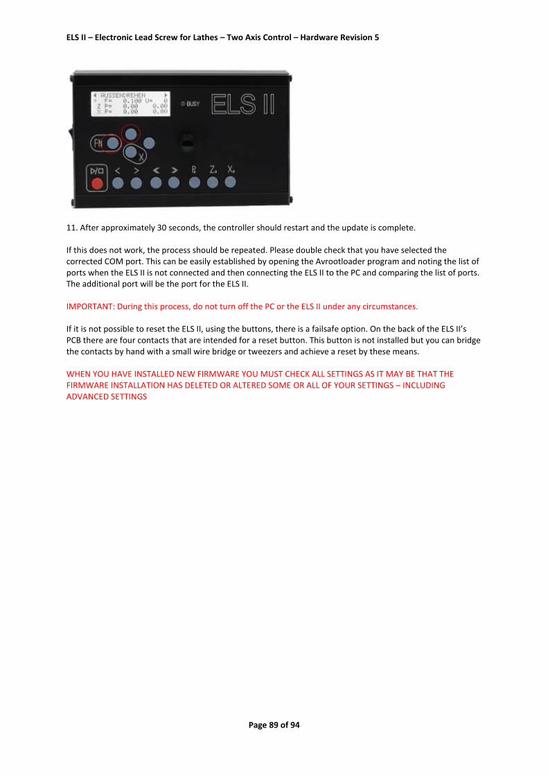
ELS II – Electronic Lead Screw for Lathes – Two Axis Control – Hardware Revision 5
Page 89 of 94
11. After approximately 30 seconds, the controller should restart and the update is complete. If this does not work, the process should be repeated. Please double check that you have selected the corrected COM port. This can be easily established by opening the Avrootloader program and noting the list of ports when the ELS II is not connected and then connecting the ELS II to the PC and comparing the list of ports. The additional port will be the port for the ELS II. IMPORTANT: During this process, do not turn off the PC or the ELS II under any circumstances. If it is not possible to reset the ELS II, using the buttons, there is a failsafe option. On the back of the ELS II’s PCB there are four contacts that are intended for a reset button. This button is not installed but you can bridge the contacts by hand with a small wire bridge or tweezers and achieve a reset by these means. WHEN YOU HAVE INSTALLED NEW FIRMWARE YOU MUST CHECK ALL SETTINGS AS IT MAY BE THAT THE FIRMWARE INSTALLATION HAS DELETED OR ALTERED SOME OR ALL OF YOUR SETTINGS – INCLUDING ADVANCED SETTINGS

ELS II – Electronic Lead Screw for Lathes – Two Axis Control – Hardware Revision 5
Page 90 of 94
Appendix 1 Mounting the HEDS Type Encoder: Here is an excerpt from the original data sheet of the HEDS5540, which you can also download from our website:

ELS II – Electronic Lead Screw for Lathes – Two Axis Control – Hardware Revision 5
Page 91 of 94

ELS II – Electronic Lead Screw for Lathes – Two Axis Control – Hardware Revision 5
Page 92 of 94
Appendix 2: Installing the AMT103-V Encoder:
Source: Datasheet for the encoder from the manufacturer (CUI Inc) Other types of encoders may be used but, for optimal operation, the encoder’s CPR value should be 400 steps per revolution. While encoders with 600 or 800 CPR values will still work, the higher CPR values do not offer any advantages. Rather - because the ELS II can only process only a finite number of pulses per second – the maximum speed may be limited.

ELS II – Electronic Lead Screw for Lathes – Two Axis Control – Hardware Revision 5
Page 93 of 94
Appendix 3: Wall Mounting While the ELS II may be attached directly to a machine, I would recommend mounting it to VESA mount, as sold for monitors and televisions. These are movable arms that have a mounting plate with standardized hole patterns. The VESA 100 type, is the correct size for the ELS II. These can be found, on EBay for around 8-10 Euros. On end of the arm is screwed to the wall, while the mounting plate to attach the rear of the ELS II housing. To do so, you will need to open the housing, on the right hand side, by removing the 4 Torx screws on that side. After loosening the side panel you can simply pull out the rear panel, install it to the VESA mount and reassemble the housing. The brackets usually look like this, but table holders are also available.

ELS II – Electronic Lead Screw for Lathes – Two Axis Control – Hardware Revision 5
Page 94 of 94
Disposal This device must not be disposed of with household waste!
Contact Details:
Manufacturer: Rocketronics.de
Louis Schreyer Dipl.-Ing (FH) Hugo Grotius-Str. 18 27404 Zeven GERMANY
Tel: +49 (0)4281 958210 Email: [email protected]
VAT-ID: DE813546414 WEEE-Reg. No. DE 35691149