Twist ‘n’ Lock 29090 & 29120 Manual Toilets -...
9
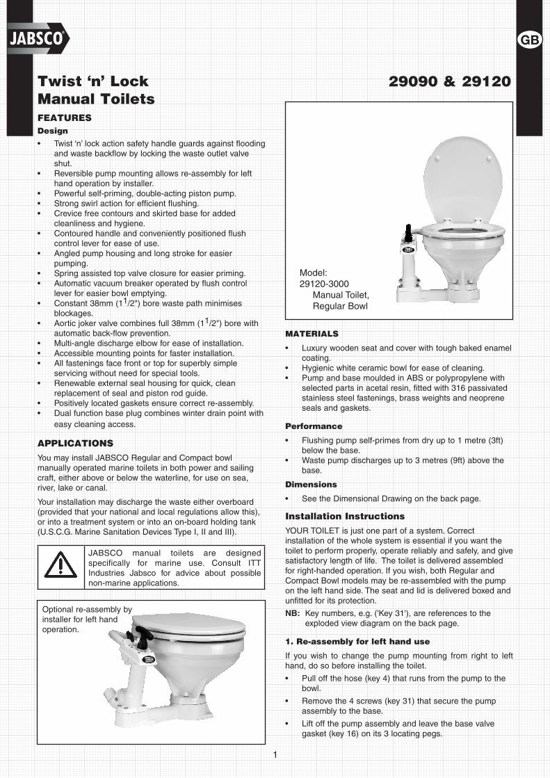
1 Optional re-assembly by installer for left hand operation. Twist ‘n’ Lock Manual Toilets FEATURES Design Twist ‘n’ lock action safety handle guards against flooding • and waste backflow by locking the waste outlet valve shut. Reversible pump mounting allows re-assembly for left • hand operation by installer. Powerful self-priming, double-acting piston pump. • Strong swirl action for efficient flushing. • Crevice free contours and skirted base for added • cleanliness and hygiene. Contoured handle and conveniently positioned flush • control lever for ease of use. Angled pump housing and long stroke for easier • pumping. Spring assisted top valve closure for easier priming. • Automatic vacuum breaker operated by flush control • lever for easier bowl emptying. Constant 38mm (1 • 1 /2") bore waste path minimises blockages. Aortic joker valve combines full 38mm (1 • 1 /2") bore with automatic back-flow prevention. Multi-angle discharge elbow for ease of installation. • Accessible mounting points for faster installation. • All fastenings face front or top for superbly simple • servicing without need for special tools. Renewable external seal housing for quick, clean • replacement of seal and piston rod guide. Positively located gaskets ensure correct re-assembly. • Dual function base plug combines winter drain point with • easy cleaning access. APPLICATIONS You may install JABSCO Regular and Compact bowl manually operated marine toilets in both power and sailing craft, either above or below the waterline, for use on sea, river, lake or canal. Your installation may discharge the waste either overboard (provided that your national and local regulations allow this), or into a treatment system or into an on-board holding tank (U.S.C.G. Marine Sanitation Devices Type I, II and III). JABSCO manual toilets are designed specifically for marine use. Consult ITT Industries Jabsco for advice about possible non-marine applications. MATERIALS Luxury wooden seat and cover with tough baked enamel • coating. Hygienic white ceramic bowl for ease of cleaning. • Pump and base moulded in ABS or polypropylene with • selected parts in acetal resin, fitted with 316 passivated stainless steel fastenings, brass weights and neoprene seals and gaskets. Performance Flushing pump self-primes from dry up to 1 metre (3ft) • below the base. Waste pump discharges up to 3 metres (9ft) above the • base. Dimensions See the Dimensional Drawing on the back page. • Installation Instructions YOUR TOILET is just one part of a system. Correct installation of the whole system is essential if you want the toilet to perform properly, operate reliably and safely, and give satisfactory length of life. The toilet is delivered assembled for right-handed operation. If you wish, both Regular and Compact Bowl models may be re-assembled with the pump on the left hand side. The seat and lid is delivered boxed and unfitted for its protection. NB: Key numbers, e.g. ('Key 31'), are references to the exploded view diagram on the back page. 1. Re-assembly for left hand use If you wish to change the pump mounting from right to left hand, do so before installing the toilet. Pull off the hose (key 4) that runs from the pump to the • bowl. Remove the 4 screws (key 31) that secure the pump • assembly to the base. Lift off the pump assembly and leave the base valve • gasket (key 16) on its 3 locating pegs. 29090 & 29120 Model: 29120-3000 Manual Toilet, Regular Bowl
-
Upload
nguyentuyen -
Category
Documents
-
view
221 -
download
0
Transcript of Twist ‘n’ Lock 29090 & 29120 Manual Toilets -...
1
Optional re-assembly by installer for left hand operation.
Twist ‘n’ Lock Manual ToiletsFEATURESDesign
Twist ‘n’ lock action safety handle guards against flooding •and waste backflow by locking the waste outlet valve shut.Reversible pump mounting allows re-assembly for left •hand operation by installer.Powerful self-priming, double-acting piston pump.•Strong swirl action for efficient flushing.•Crevice free contours and skirted base for added •cleanliness and hygiene.Contoured handle and conveniently positioned flush •control lever for ease of use.Angled pump housing and long stroke for easier •pumping.Spring assisted top valve closure for easier priming.•Automatic vacuum breaker operated by flush control •lever for easier bowl emptying.Constant 38mm (1• 1/2") bore waste path minimises blockages.Aortic joker valve combines full 38mm (1• 1/2") bore with automatic back-flow prevention.Multi-angle discharge elbow for ease of installation.•Accessible mounting points for faster installation.•All fastenings face front or top for superbly simple •servicing without need for special tools.Renewable external seal housing for quick, clean •replacement of seal and piston rod guide.Positively located gaskets ensure correct re-assembly.•Dual function base plug combines winter drain point with •easy cleaning access.
APPLICATIONS
You may install JABSCO Regular and Compact bowl manually operated marine toilets in both power and sailing craft, either above or below the waterline, for use on sea, river, lake or canal.
Your installation may discharge the waste either overboard (provided that your national and local regulations allow this), or into a treatment system or into an on-board holding tank (U.S.C.G. Marine Sanitation Devices Type I, II and III).
JABSCO manual toilets are designed specifically for marine use. Consult ITT Industries Jabsco for advice about possible non-marine applications.
MATERIALS
Luxury wooden seat and cover with tough baked enamel •coating.Hygienic white ceramic bowl for ease of cleaning.•Pump and base moulded in ABS or polypropylene with •selected parts in acetal resin, fitted with 316 passivated stainless steel fastenings, brass weights and neoprene seals and gaskets.
Performance
Flushing pump self-primes from dry up to 1 metre (3ft) •below the base.Waste pump discharges up to 3 metres (9ft) above the •base.
Dimensions
See the Dimensional Drawing on the back page.•
Installation Instructions
YOUR TOILET is just one part of a system. Correct installation of the whole system is essential if you want the toilet to perform properly, operate reliably and safely, and give satisfactory length of life. The toilet is delivered assembled for right-handed operation. If you wish, both Regular and Compact Bowl models may be re-assembled with the pump on the left hand side. The seat and lid is delivered boxed and unfitted for its protection.
NB: Key numbers, e.g. ('Key 31'), are references to the exploded view diagram on the back page.
1. Re-assembly for left hand use
If you wish to change the pump mounting from right to left hand, do so before installing the toilet.
Pull off the hose (key 4) that runs from the pump to the •bowl.
Remove the 4 screws (key 31) that secure the pump •assembly to the base.
Lift off the pump assembly and leave the base valve •gasket (key 16) on its 3 locating pegs.
29090 & 29120
Model: 29120-3000
Manual Toilet, Regular Bowl

2
Remove the 4 bolts (key 11) that secure the bowl to the •base.
Rotate the bowl 180° and re-secure it, using the nylon •washers (key 14) to protect the ceramic from the stainless steel washers and nuts (key 13,12).
Rotate the pump assembly 180° and re-secure it.•
Rotate the push-fit intake elbow (key 6) 180° and refit •the hose between the pump and the bowl.
2. Location
Select a location that will give sufficient clearance all •round and above the toilet. Ensure that there is room to operate the pump and that there is access to the drain plug at the end of the base.
The mounting surface must be flat, rigid and strong •enough to support a man's weight and should be at least 50mm (2") wider and 50mm (2") deeper than the base of the toilet.
You will need sufficient clearance below the mounting •surface to be able to secure the mounting bolts.
The seat and lid should be able to swing up and over at •least 110°, so that they will not fall forward when the craft heels or pitches. When they are swung up they must be supported so that the hinges are not strained
3. Mounting
YOU WILL need:
❏ 4 x 8mm (5/16") diameter stainless steel bolts of length to suit the thickness of the mounting surface.
❏ 4 stainless steel nuts, preferably self-locking. If you do not use self-locking nuts you will need some nut-locking compound.
❏ 8 large stainless steel washers not more than 21mm (13/16") diameter.
❏ A small tube of white silicone sealant.
Offer up the toilet in the selected position and, using the •holes in the base as a guide, mark the positions for the 4 bolt holes on the mounting surface. Remove the toilet and drill 4 vertical holes of 9mm diameter through the mounting surface.
Apply a bead of white silicone sealant to the outer rim of •the bottom base.
Bolt down the toilet and tighten the fastenings securely. If •you are not using self-locking nuts, use nut-locking compound.
4. Through Hull Fittings
YOU WILL need:
❏ 19mm (3/4") bore seacock for the flushing water inlet, and, if you are discharging the waste overboard, a 38 mm (11/2") bore seacock for the waste outlet.
Follow the seacock manufacturer's own instructions •concerning materials and methods of installation.
Ensure the inlet seacock is positioned where it will be •below the waterline at all times when the craft is underway, and also ensure that any outlet seacock is both aft of, and higher than, the inlet seacock.
HAZARD RISK - Through Hull Fittings
If the installation of the toilet results in it being connected to ANY through-hull fitting that may possibly be below the waterline at ANY time, whether when the craft is at rest, underway and heeling or rolling or pitching, you must install the toilet in accordance with these Installation Instructions. If you do not, water may flood in, causing the craft to sink, which may result in loss of life.
FOLLOW THESE INSTRUCTIONS!
HAZARD RISK - Accidental Damage
If the toilet is connected to ANY through-hull fittings and if the toilet or pipework is damaged, water may flood in causing the craft to sink, which may result in loss of life.
Therefore, if you are making connections between the toilet and ANY through-hull fittings that may possibly be below the waterline at ANY time, full bore seacocks MUST be fitted to those hull fittings, to allow them to be shut off.
The seacocks MUST also be positioned where they are easily accessible to all users of the toilet. If, for any reason, it is not possible to do this, then secondary full bore marine quality valves MUST be fitted to the hoses where they are easily accessible.
USE SEACOCKS!
CAUTION: Use lever operated, full bore marine seacocks and valves. The use of screw-down gate valves is not recommended.
5. Pipework - selection of correct method
YOU MUST select the correct method for the inlet pipework from 2 options and for the outlet pipework from 4 options, according to whether the toilet is above or below the waterline, and to whether it discharges the waste overboard or into an on-board holding tank.
HAZARD RISK - Pipework Becomes Loose
If the toilet is connected to ANY through-hull fittings and if the pipework becomes disconnected, either from a through-hull fitting or seacock, or from the toilet or any secondary valve, water may flood in and may cause the craft to sink, which may result in loss of life.
Therefore the ends of ALL flexible hoses fitted directly or indirectly between the toilet and ANY through-hull fitting that may possibly be below the waterline at ANY time, MUST be secured to the hose tails to which they are connected, using two stainless steel worm-drive hose clips.
USE HOSE CLIPS!
5.1 Pipework - General instructions for all options
YOU WILL need:
❏ Spiral reinforced smooth bore flexible hoses for both the 19mm (3/4") id inlet and the 38mm (11/2") id outlet pipework
❏ Two stainless steel worm-drive hose clips for every hose tail connection (4, 6 or 8).

3
Figure 1. Figure 2.
Secure the hose runs so that the hoses cannot move •and chafe, and so that they do not exert any leverage on the hose tail fittings to which they are connected, as this may cause adjacent joints to leak.
Avoid sharp bends in the hoses that may cause them to •become kinked.
Keep all pipework lengths as short as possible, whilst •complying with these instructions. Unnecessary inlet or outlet hose length just makes the toilet harder to pump.
If it is difficult to fit the hose onto the hose tails of the •toilet or seacocks, lubricate it with water, or soften the hose by dipping the end of it in hot water.
CAUTION: Do not apply flame to the hose. Do not apply flame or any heat to the plastic hose tails on the toilet. Do not use oils, greases or synthetic lubricants. Do not apply sealing compounds to any hose connections. Do not over tighten hose clips. Any of these actions may result in cracking or breakage of the plastic parts of the toilet.
Secure the ends of all hoses to the hose tails with two •stainless steel worm-drive hose clips, ensuring that all inlet connections are airtight and that all outlet connections are watertight.
The Discharge Elbow (key 34) may be rotated 360° to •suit your installation. Always slacken the 2 securing screws, adjust the discharge elbow to the required position and re-tighten the 2 securing screws BEFORE you connect the hose to it.
CAUTION: Failure to follow this procedure may result in leaks between the discharge elbow and the pump cylinder.
5.2 Inlet Pipework - 2 options
Option 1: Toilet below the waterline
YOU MUST fit a 19mm (3/4") Vented Loop fitting, Jabsco part number 29015-0000.
Run the inlet hose by the most direct route from the inlet •seacock to the flushing pump inlet tail.
Remove the white hose supplied with the toilet, which •connects the flushing pump outlet tail to the elbow (key 6).
Rotate the intake seal (key 5) so that the elbow points •upwards.
Replace the white hose with a longer length of 19mm •(3/4") id hose and arrange it to form an anti-syphon loop whose highest point is at least 20cm (8") above the highest possible waterline, and fit the Vented Loop at the highest point.
• Secure the ends of all hoses with two stainless steel worm-drive hose clips.
HAZARD RISK - Bowl Rim Below Waterline
If the toilet is connected to ANY through-hull fittings, and if the rim of the bowl falls below the waterline, water may flood in causing the craft to sink, which may result in loss of life.
Therefore, if the rim of the toilet is less than 20cm (8") above the waterline when the craft is at rest, or if there is ANY possibility that the rim of the bowl may be below the waterline at ANY time, a ventilated anti-syphon loop MUST be fitted in any pipework connected to a through-hull fitting, irrespective of whether inlet or outlet.
USE VENTED LOOPS!
SPECIAL NOTE 1: The smaller bore inlet pipework is more hazardous than the larger outlet pipework. Unless there is a ventilated anti-syphon loop in the inlet pipework, water will flow into the bowl whenever both the inlet seacock is open and the rim of the bowl is below the actual waterline.
Although moving the Flush Control Lever (key 23) to the "Shut" position will restrict the flow, this lever CANNOT be relied upon as a shut-off valve.
SPECIAL NOTE 2: Making a loop in the hose without fitting a vent may be just as hazardous as no loop at all, because water may syphon over a loop. It is the vent that actually prevents the syphon.
19mm (3/4")VENTED LOOP
38mm (1 1/2") VENTED LOOP
AT LEAST 20cm (8")
HEELED
WATERLINE
38mm (1 1/2") OUTLET
SEACOCK
19mm (3/4")INLET
SEACOCK
OPTIONAL: 38mm (1 1/2") VENTED LOOP
19mm (3/4")INLET
SEACOCK
38mm (1 1/2") OUTLET
SEACOCK
AT LEAST 30cm (12")
HEELED
WATER LINE
OPTIONAL NON-RETURN VALVE
DISCHARGE ELBOW

4
All dimensions in millimetres with inch equivalents in brackets.
Option 2: Toilet always above the heeled waterline
YOU MAY need A 19mm (3/4") non-return valve, Jabsco part number 29295-1011
Run the inlet hose by the most direct route from the inlet •seacock to the flushing pump inlet tail.
For maximum convenience of use, install a 19mm (• 3/4") in-line non-return valve next to the inlet seacock, which will ensure that the pump remains primed in between usages.
5.3 Outlet Pipework - 4 options
Option 1: Toilet below the waterline and discharging overboard. (See Figure 1 on Page 3)
YOU MUST fit a 38mm (11/2") Vented Loop fitting, Jabsco part number 29015-0010.
Arrange the outlet hose to form a loop which is at least •20cm (8") above the highest possible waterline, and fit the vented loop at the highest point.
Option 2: Toilet above the waterline, and discharging overboard. (See Figure 2 on Page 3)
YOU MAY fit a 38mm (11/2") Vented Loop fitting, Jabsco part number 29015-0010.
Run the outlet hose up from the discharge elbow to form •a loop at least 30cm (12") higher than the discharge elbow.
If you fit a vented loop at the top of the hose loop this •will ensure that you can keep some water in the base of the toilet without risk of it being siphoned away.
Option 3: Toilet waste discharging into holding tank, top of holding tank above discharge elbow at anytime. (See Figure 3 below)
YOU MUST fit a 38mm (11/2") Vented loop fitting, Jabsco part number 29015-0010.
• If there is ANY possibility that the discharge elbow may be below the top of the tank at ANY time, a ventilated anti-syphon loop must be fitted in the outlet pipework to ensure that the contents of the tank do not syphon out through the bowl.
Arrange the outlet hose to form a loop which is at least •20 cm (8") above the highest possible level that the tank may reach, and fit the Vented Loop at that highest point.
Option 4: Toilet waste discharging into holding tank, discharge elbow always above top of holding tank. (See Figure 3 below)
Run the outlet hose up from the discharge elbow to form •a loop at least 30cm (12") higher than the discharge elbow.
This will create a water seal at the Joker Valve that will •prevent bad odours from escaping through the toilet.
YOU MAY fit a 38mm (11/2") Vented Loop fitting, Jabsco part number 29015-0010.
• If you fit a vented loop at the top of the hose loop this will ensure that you can keep some water in the base of the toilet without risk of it being siphoned away.
38mm (1 1/2") VENTED LOOP HOLDING TANK
VENT PIPES
AT LEAST 20cm (8")
OPTIONAL 38mm (1 1/2") VENTED
LOOP
AT LEAST 30cm (12")
DISCHARGE ELBOW
Option 3Top of Holding Tank above
Discharge Elbow at any time
Option 3Holding Tank below
Discharge Elbow
Figure 3

5
6. Testing
Refer to the Operating Instructions and follow the procedure "2 Normal use".
• If the flushing pump is hard to prime half fill the bowl with fresh water.
7. Safety
Ensure that this INSTRUCTION MANUAL reaches the owner, skipper or operator of the craft as it contains essential safety information.
ON COMPLETION OF INSTALLATION:
- SHUT THE FLUSH CONTROL ( )
- CLOSE BOTH SEACOCKS
Operating Instructions
The toilet is one of the most used pieces of equipment on your boat. Correct operation of the toilet is essential for the safety and comfort of your crew and craft.
1. First use
After periods without use the toilet may benefit from lubrication.
Open inlet and outlet seacocks (and secondary valves if •fitted).
Half fill the bowl with warm fresh water.•
Keeping the Flush Control Lever (key 23) in the Shut •( ) position, pump out the warm water.
2. Normal use
Open inlet and outlet seacocks (and secondary valves if fitted).
Before use, ensure that there is enough water in the •bowl to prevent the toilet paper becoming compacted at the bottom of the bowl.
If the bowl is empty, move the Flush Control Lever (key 23) to the Open ( ) position and pump the handle (key 17) up and down until the flushing pump is primed and water enters the bowl.
Then Shut ( ) the Flush Control.
Operate the pump with long, smooth strokes for efficient •and easy operation.
During use, pump as necessary to keep the contents of •the bowl low enough for comfort.
Use good quality hard or soft household toilet paper, but •do not use more than necessary.
After use, keep the Flush Control Shut (• ) and pump until the bowl is empty.
When the bowl is empty, Open (• ) the Flush Control again, and continue to pump until all waste has either left the boat, or reached the holding tank (allow 7 complete up/down strokes per metre (yard) length of discharge pipework).
Then Shut ( ) the Flush Control and pump until the bowl is empty. Always leave the bowl empty to minimise odour and spillage.
AFTER USE:
- SHUT ( ) THE FLUSH CONTROL.
- SHUT BOTH SEACOCKS
HAZARD RISK - Accidental Damage
If the toilet is connected to ANY through-hull fittings that are below the waterline at any time, and if the toilet or pipework is damaged, water may flood in, causing the craft to sink, which may result in loss of life.
Therefore, after every usage, both seacocks (or secondary valves) MUST be shut.
Whenever your craft is unattended, even if only for a very short period of time, both seacocks (even if secondary valves are fitted) MUST be shut.
Ensure that ALL users understand how to operate the •toilet system correctly and safely, including seacocks and secondary valves.
Take special care to instruct children, the elderly and •visitors.
SHUT SEACOCKS!
NOTE: Do not put anything in the toilet unless you have eaten it first, except toilet paper. Do not put in: Sanitary Towels, Wet Strength Tissues, Cotton Wool, Cigarettes, Matches, Chewing Gum or any solid objects, Petrol, Diesel, Oil, Solvents of any kind or water more than hand hot.
6
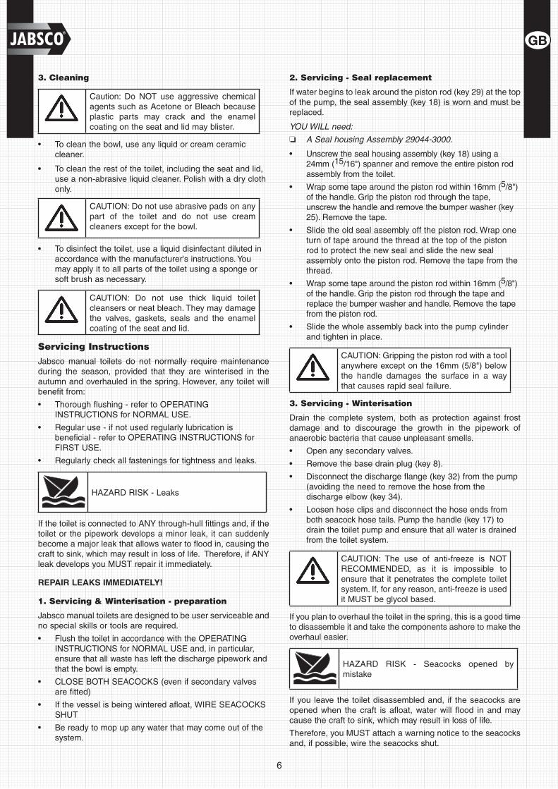
3. Cleaning
Caution: Do NOT use aggressive chemical agents such as Acetone or Bleach because plastic parts may crack and the enamel coating on the seat and lid may blister.
To clean the bowl, use any liquid or cream ceramic •cleaner.
To clean the rest of the toilet, including the seat and lid, •use a non-abrasive liquid cleaner. Polish with a dry cloth only.
CAUTION: Do not use abrasive pads on any part of the toilet and do not use cream cleaners except for the bowl.
• To disinfect the toilet, use a liquid disinfectant diluted in accordance with the manufacturer's instructions. You may apply it to all parts of the toilet using a sponge or soft brush as necessary.
CAUTION: Do not use thick liquid toilet cleansers or neat bleach. They may damage the valves, gaskets, seals and the enamel coating of the seat and lid.
Servicing Instructions
Jabsco manual toilets do not normally require maintenance during the season, provided that they are winterised in the autumn and overhauled in the spring. However, any toilet will benefit from:
Thorough flushing - refer to OPERATING •INSTRUCTIONS for NORMAL USE.
Regular use - if not used regularly lubrication is •beneficial - refer to OPERATING INSTRUCTIONS for FIRST USE.
Regularly check all fastenings for tightness and leaks.•
HAZARD RISK - Leaks
If the toilet is connected to ANY through-hull fittings and, if the toilet or the pipework develops a minor leak, it can suddenly become a major leak that allows water to flood in, causing the craft to sink, which may result in loss of life. Therefore, if ANY leak develops you MUST repair it immediately.
REPAIR LEAKS IMMEDIATELY!
1. Servicing & Winterisation - preparation
Jabsco manual toilets are designed to be user serviceable and no special skills or tools are required.
Flush the toilet in accordance with the OPERATING •INSTRUCTIONS for NORMAL USE and, in particular, ensure that all waste has left the discharge pipework and that the bowl is empty.
CLOSE BOTH SEACOCKS (even if secondary valves •are fitted)
If the vessel is being wintered afloat, WIRE SEACOCKS •SHUT
Be ready to mop up any water that may come out of the •system.
2. Servicing - Seal replacement
If water begins to leak around the piston rod (key 29) at the top of the pump, the seal assembly (key 18) is worn and must be replaced.
YOU WILL need:
❏ A Seal housing Assembly 29044-3000.
Unscrew the seal housing assembly (key 18) using a •24mm (15/16") spanner and remove the entire piston rod assembly from the toilet.
Wrap some tape around the piston rod within 16mm (• 5/8") of the handle. Grip the piston rod through the tape, unscrew the handle and remove the bumper washer (key 25). Remove the tape.
Slide the old seal assembly off the piston rod. Wrap one •turn of tape around the thread at the top of the piston rod to protect the new seal and slide the new seal assembly onto the piston rod. Remove the tape from the thread.
Wrap some tape around the piston rod within 16mm (• 5/8") of the handle. Grip the piston rod through the tape and replace the bumper washer and handle. Remove the tape from the piston rod.
Slide the whole assembly back into the pump cylinder •and tighten in place.
CAUTION: Gripping the piston rod with a tool anywhere except on the 16mm (5/8") below the handle damages the surface in a way that causes rapid seal failure.
3. Servicing - Winterisation
Drain the complete system, both as protection against frost damage and to discourage the growth in the pipework of anaerobic bacteria that cause unpleasant smells.
Open any secondary valves.•
Remove the base drain plug (key 8).•
Disconnect the discharge flange (key 32) from the pump •(avoiding the need to remove the hose from the discharge elbow (key 34).
Loosen hose clips and disconnect the hose ends from •both seacock hose tails. Pump the handle (key 17) to drain the toilet pump and ensure that all water is drained from the toilet system.
CAUTION: The use of anti-freeze is NOT RECOMMENDED, as it is impossible to ensure that it penetrates the complete toilet system. If, for any reason, anti-freeze is used it MUST be glycol based.
If you plan to overhaul the toilet in the spring, this is a good time to disassemble it and take the components ashore to make the overhaul easier.
HAZARD RISK - Seacocks opened by mistake
If you leave the toilet disassembled and, if the seacocks are opened when the craft is afloat, water will flood in and may cause the craft to sink, which may result in loss of life.
Therefore, you MUST attach a warning notice to the seacocks and, if possible, wire the seacocks shut.

7
ATTACH WARNING NOTICE!
If you are not disassembling the toilet:
Reconnect all hose ends and secure them with their •hose clips.
Replace the base drain plug securely.•
Replace the joker valve in the discharge elbow. •
Reconnect the discharge elbow and hose to the cylinder •using the discharge flange, whilst relieving any leverage from the discharge hose. If you do not, the joint may not seal.
Fasten down the seat, lid and pump handle to prevent •use and attach a warning notice.
4. Servicing - Overhaul
YOU WILL need:
❏ A Service Kit, part number 29045-3000, which contains all wearing parts - refer to the PARTS LIST for details.
Remove the pump assembly as follows:
Loosen hose clips; disconnect the inlet hose and the •flushing water hose (key 4) from the top of the pump.
Remove the 2 screws (key 31) that secure the discharge •flange (key 32) that holds the discharge elbow (key 34) and hose to the pump cylinder (key 28).
Do NOT remove the hose from the discharge elbow.•
Remove the 4 screws (key 31) that secure the pump •cylinder to the base.
Lift off the pump assembly and pick up the base valve •gasket (key 16) and the joker valve (key 33).
Dismantle the pump assembly as follows:
Remove the 6 screws (key 26) that secure the valve cover •(key 27).
Open (• ) the Flush Control (key 23) before lifting off the valve cover assembly and picking up the top valve gasket (key 21), the valve seat (key 19) and the valve spring (key 35).
Remove the handle and the seal assembly by following •the SERVICING INSTRUCTIONS for SEAL REPLACEMENT.
Withdraw the piston assembly (key 29) and prise off the •piston O-ring (key 30).
Do NOT remove the bowl from the base•
• Clean and disinfect all parts - refer to OPERATING INSTRUCTIONS for CLEANING. Remove scale from the cylinder bore.
• Inspect the top and bottom valve gaskets (key 21) and the joker valve, and renew them if they are damaged, stiff or covered with scale. Automatically renew the seal assembly and the piston O-ring. Use the other parts in the kit as necessary.
Reassemble the pump as follows:
Push on the new O-ring (key 30) and lubricate with •petroleum jelly (vaseline).
Following the SERVICING INSTRUCTIONS for SEAL •REPLACEMENT fit the new seal assembly (key 18), the piston assembly (key 29) and the handle (key 17).
Lubricate pump cylinder bore with petroleum jelly •(Vaseline).
Locate the valve seat (key 19) on top of the cylinder, •locate the top valve gasket (key 21) on its pegs on top of the cylinder, locate the valve spring (key 35) on its peg in the valve cover, and Open ( ) the Flush Control (key 23) before refitting the valve cover (key 27).
Locate the joker valve (key 33) in the discharge elbow •(key 34).
Secure the discharge elbow and hose to the cylinder, •using the discharge flange (key 32), BEFORE you refit the pump assembly to the base (key 7), so that the joint is not under leverage from the discharge hose. If you do not, the joint may not seal.
Locate the bottom valve gasket (key 16) on its pegs on •the base.
Secure the pump assembly to the base whilst relieving •any leverage from the discharge hose. If you do not, the joint may not seal.
Examine all hoses throughout their length for chafe, •kinks and splits under hose clips. Check all hose clips for corrosion and replace worn or damaged parts.
Reconnect all loose hose ends and secure them with •their hose clips.
Ensure that the base drain plug (key 8) is securely in •place.
CAUTION: Do NOT lubricate top or bottom valve gaskets. Do NOT apply sealing compounds to any gaskets or hose connections.
5. Servicing - Testing
REFER to the OPERATING INSTRUCTIONS and follow the procedure for "2. Normal use".
If the flushing pump is hard to prime, half-fill the bowl •with fresh water.
ON COMPLETION OF SERVICING:
SHUT (• ) THE FLUSH CONTROL
CLOSE BOTH SEACOCKS.•
8
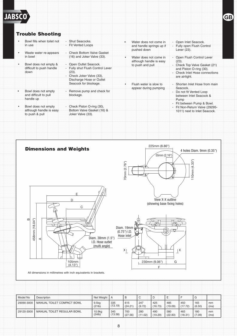
All dimensions in millimetres with inch equivalents in brackets.
Dimensions and Weights
Trouble ShootingBowl fills when toilet not •in use
Shut Seacocks.-Fit Vented Loops-
Waste water re-appears •in bowl
Check Bottom Valve Gasket -(16) and Joker Valve (33).
Bowl does not empty & •difficult to push handle down
Open Outlet Seacock.-Fully shut Flush Control Lever -(23). Check Joker Valve (33), -Discharge Hose or Outlet Seacock for blockage.
• Bowl does not empty and difficult to pull handle up
Remove pump and check for -blockage.
Bowl does not empty •although handle is easy to push & pull
Check Piston O-ring (30), -Bottom Valve Gasket (16) & Joker Valve (33).
• Water does not come in and handle springs up if pushed down
Open Inlet Seacock.- Fully open Flush Control -Lever (23).
Water does not come in •although handle is easy to push and pull
Open Flush Control Lever -(23). Check Top Valve Gasket (21) -and Piston O-ring (30).Check Inlet Hose connections - are airtight.
• Flush water is slow to appear during pumping
Shorten Inlet Hose from main -Seacock.Do not fit Vented Loop - between Inlet Seacock & PumpFit between Pump & Bowl.- Fit Non-Return Valve (29295-- 1011) next to Inlet Seacock.
View X-X outline(showing base fixing holes)
Diam. 19mm (0.75") I.D. Hose inlet
Diam. 38mm (1.5") I.D. Hose outlet
(multi angle)
4 holes Diam. 9mm (0.35")
Model No Description Net Weight A B C D E F G
29090-3000 MANUAL TOILET COMPACT BOWL 9.5kg(21lb)
335 (13.19)
615(24.21)
247(9.72)
425(16.73)
485(19.09)
450(17.72)
165(6.50)
mm(ins)
29120-3000 MANUAL TOILET REGULAR BOWL 10.9kg (24lb)
345 (13.58)
700(27.56)
280(11.02)
490(19.29)
580(22.83)
465(18.31)
180(7.09)
mm(ins)
9
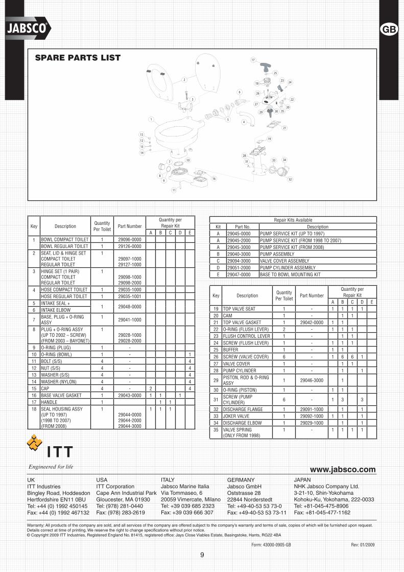
SPARE PARTS LIST
Key DescriptionQuantity Per Toilet
Part NumberQuantity per Repair Kit
A B C D E
1 BOWL COMPACT TOILET 1 29096-0000BOWL REGULAR TOILET 1 29126-0000
2 SEAT, LID & HINGE SETCOMPACT TOILETREGULAR TOILET
129097-100029127-1000
3 HINGE SET (1 PAIR)COMPACT TOILETREGULAR TOILET
1 29098-100029098-2000
4 HOSE COMPACT TOILET 1 29035-1000HOSE REGULAR TOILET 1 29035-1001
5 INTAKE SEAL +1 29048-0000
6 INTAKE ELBOW
7 BASE, PLUG + O-RING ASSY
1 29041-1000
8 PLUG + O-RING ASSY(UP TO 2002 – SCREW)(FROM 2003 – BAYONET)
129028-100029028-2000
9 O-RING (PLUG) 1 -10 O-RING (BOWL) 1 - 111 BOLT (S/S) 4 - 412 NUT (S/S) 4 - 413 WASHER (S/S) 4 - 414 WASHER (NYLON) 4 - 415 CAP 4 - 2 416 BASE VALVE GASKET 1 29043-0000 1 1 117 HANDLE 1 1 118 SEAL HOUSING ASSY
(UP TO 1997)(1998 TO 2007)(FROM 2008)
129044-000029044-200029044-3000
1 1 1
Key DescriptionQuantity Per Toilet
Part NumberQuantity per Repair Kit
A B C D E19 TOP VALVE SEAT 1 - 1 1 1 120 CAM 1 - 1 121 TOP VALVE GASKET 1 29042-0000 1 122 O-RING (FLUSH LEVER) 2 - 1 1 123 FLUSH CONTROL LEVER 1 - 1 124 SCREW (FLUSH LEVER) 1 - 1 1 125 BUFFER 1 - 1 126 SCREW (VALVE COVER) 6 - 1 6 6 127 VALVE COVER 1 - 1 128 PUMP CYLINDER 1 - 1 1
29 PISTON, ROD & O-RING ASSY 1 29046-3000 1
30 O-RING (PISTON) 1 - 1 1
31 SCREW (PUMP CYLINDER) 6 - 1 3 3
32 DISCHARGE FLANGE 1 29091-1000 1 133 JOKER VALVE 1 29092-1000 1 1 134 DISCHARGE ELBOW 1 29029-1000 1 135 VALVE SPRING
(ONLY FROM 1998)1 - 1 1 1 1
Repair Kits AvailableKit Part No. DescriptionA 29045-0000 PUMP SERVICE KIT (UP TO 1997)A 29045-2000 PUMP SERVICE KIT (FROM 1998 TO 2007)A 29045-3000 PUMP SERVICE KIT (FROM 2008)B 29040-3000 PUMP ASSEMBLYC 29094-3000 VALVE COVER ASSEMBLYD 29051-2000 PUMP CYLINDER ASSEMBLYE 29047-0000 BASE TO BOWL MOUNTING KIT
Form: 43000-0905-GB Rev: 01/2009
USAITT CorporationCape Ann Industrial ParkGloucester, MA 01930Tel: (978) 281-0440Fax: (978) 283-2619
UKITT IndustriesBingley Road, HoddesdonHertfordshire EN11 0BUTel: +44 (0) 1992 450145Fax: +44 (0) 1992 467132
JAPANNHK Jabsco Company Ltd.3-21-10, Shin-YokohamaKohoku-Ku, Yokohama, 222-0033Tel: +81-045-475-8906Fax: +81-045-477-1162
ITALYJabsco Marine ItaliaVia Tommaseo, 620059 Vimercate, MilanoTel: +39 039 685 2323Fax: +39 039 666 307
GERMANYJabsco GmbHOststrasse 2822844 NorderstedtTel: +49-40-53 53 73-0Fax: +49-40-53 53 73-11
Warranty: All products of the company are sold, and all services of the company are offered subject to the company’s warranty and terms of sale, copies of which will be furnished upon request. Details correct at time of printing. We reserve the right to change specifications without prior notice.© Copyright 2009 ITT Industries, Registered England No. 81415, registered office: Jays Close Viables Estate, Basingstoke, Hants, RG22 4BA
www.jabsco.com