

Twin-Wall System - Flue Supplies
24
Trade Catalogue Twin-Wall System Easy to Install Push Fit systems ISO 9001 FS 576960
Transcript of Twin-Wall System - Flue Supplies

Trade Catalogue
Twin-WallSystemEasy to Install Push Fit systems
iso 9001Fs 576960

Twin
- W
all s
yste
m -
Contact our sales Team: Telephone: 0844 800 6586 Fax: 01622 711 418
Intr
oduc
tion
1
About Us Flue Supplies is a family-run company with over 30 years direct experience of selling chimney products to the UK chimney trade and retail customers. All our products have been selected from quality manufacturers and are trusted by trade installers across the UK. We believe our products should give you both value for money as well as peace of mind.
JeremiasJeremias is a German manufacturer of DW-ECO 316 twin-wall insulated chimney systems, engineered in both Spain and in Germany. The high-temperature resistant twin-wall system they produce is made from 304 outer (0.4-0.6mm) and 316 inner (0.4-0.6mm) stainless steel. The twin-wall system is densely packed with rigid mineral wool insulation, of 25mm thickness (120kg/m3) designed to maintain the heat inside the system and create a better draw.
Jeremias twin-wall is suitable for burning all types of fuel in situations where a chimney system is needed to go either on the outside of a building or to be built inside where there is not an existing chimney stack.
Jeremias use a “push-fit” system for their rigid pipe where each component pushes into the following piece and a locking band (provided with all lengths, bends and adaptors) goes around the joint. O-rings are available for condensing purposes.
All of Jeremias products have been HETAS approved and quality tested.
Size RangeAvailable in 100mm (4”), 125mm (5”), 150mm (6”), 175mm (7”) and 200mm (8”) as stock items. Any larger sizes can be ordered in up to 600mm internal diameter.
Please note: all sizes are based on the internal measurement of the flue. The external size will be 2” bigger than the internal measurement.
ColoursAll of the Jeremias twin-wall system have a stainless steel finish. However, these can be powder coated to most BS or RAL colour codes if required. Matt black powder-coated components are available from stock.
Quality AssuranceAll Jeremias twin wall products are Hetas approved and come with a 25 year guarantee. They have all been tested to comply with all UK building regulations.

Twin
- W
all s
yste
m -
Email: [email protected]
Intr
oduc
tion
2
General Notes1. Flue Supplies recommends that the chimney is swept and inspected at least twice a year, ideally at the middle and end of the heating season. Failure to maintain a clean chimney can potentially cause a chimney fire and the emission of toxic gases.
2. In the event of a chimney fire, all products need to be inspected by a competent person to ensure the system is safe to use.
3. Do not burn household refuse.
4. Do not block or cover the appliance or chimney outlets.
5. Slumbering the fire for prolonged periods of time will decrease the life expectancy of the system.
6. Do not use chemical cleaners or metal brushes.
7. It is advisable to use only the fuel recommended by the appliance manufacturer. Using the wrong fuel for the system will decrease the life of the product.
8. It is a legal requirement to fit a chimney notice plate on any installation, either by the fire itself or in a utility cupboard. A carbon monoxide detector and air vent must also be fitted in the same room as the appliance.
Please be adviced that the manufacturer may change the design of the products so dimension may vary.
Product designations
• Jeremias System dw-eco 316, Certification & Installing Instructions
• HETAS -Heating Equipment Testing and Approval Scheme
• NACS- National Association of Chimney Sweeps
• Document J UK Building Regulations
• Planning Office
Installation GuidelinesFor detailed installation guidelines, please refer to the following:
0.1 dw-eco 316 Metal exhaust gas system EN 1856-1 T600 N1 D VM-L50040 G(70)
0.2 dw-eco 316 Metal exhaust gas system EN 1856-1 T450 N1 D V3-L50040 G(60)
0.3 dw-eco 316 Metal exhaust gas system EN 1856-1 T400 N1 W V2-L50040 O(30)
0.8 dw-eco 316 Metal exhaust gas system EN 1856-1 T200 P1 W V2-L50040 O(30)
Product Description
No. of Standard
Temperature Range
Pressure Range
Condensation resistence (W: Wet or D: Dry)
Corrosion resistance material of exhaust gas
system
soot FiRE resistence (G: Yes or o: No)
Distance to combustible materials (mm)

Twin
- W
all s
yste
m -
Contact our sales Team: Telephone: 0844 800 6586 Fax: 01622 711 418
Installation GuideIn
stal
latio
n G
uide
s
3
The twin-wall system is designed to be used where an existing chimney stack is not present or when the appliance is required to be used against an external wall.
Jeremias twin-wall is an easy to install “push-fit” system and a locking band is provided with each component to go around the joint (except those specified).
There are a number of important points to be aware of when installing a twin-wall system:
•A minimum of a 60mm clearance must be maintained from anything combustible at T450. See Product Designation.
• There should be as few offsets as possible and the distance between the bends should not exceed 20% of the vertical height of the chimney.
• The chimney should have an adequate clearance from the roof. Please see Document J Building Regs for more details.
• The diameter should never be reduced to less than the appliance manufacturers’ instructions.
• Provisions for sweeping must be provided.
Basic ExternalInstallations
Rain Cap
Adjustable wall Bracket
Elbow
Wall Bracket
Base Support Bracket
Wall Sleeve
Adaptor
Flue Pipe
45° Tee and Cap
Flashing
Storm Collar
Optional Guy Wire Bracket(Required if run above roof is over 1.5mtrs)
Rain Cap
Roof support
VentedFire Stop Spacer
Vitreous Flue Pipe
Twin Wall Adaptor
VentedFire Stop Spacer
VentedCeiling Support
Enclosure or Cage(The system needs to be shielded in the attic area)
The Twin Wall system should be enclosed in any upper floors to ensure that no combustibles come into contact with the system.
VentedCeiling Support

Twin
- W
all s
yste
m -
Email: [email protected]
Inst
alla
tion
Gui
dene
nts
4
• The chimney should be appropriately supported at 4mtr intervals and lateral support every 1.5mtrs. Refer to manufacturer instructions for more details.
• Joints within walls, ceiling or floors should NOT be made.
• Where there is a risk of combustible materials coming into contact with the system, the minimum distance from combustible materials (60mm) must be maintained throughout by a permanent enclosure or shield.
• When the system goes through a wall, a sleeve should be used and weather-proofed as required.
• Components should not be modified.
• A chimney notice plate, carbon monoxide detector and air vent should be installed in the same room as the appliance.
Basic InternalInstallations
Flashing
Storm Collar
Optional Guy Wire Bracket(Required if run above roof is over 1.5mtrs)
Rain Cap
Roof support
VentedFire Stop Spacer
Vitreous Flue Pipe
Twin Wall Adaptor
VentedFire Stop Spacer
VentedCeiling Support
Enclosure or Cage(The system needs to be shielded in the attic area)
The Twin Wall system should be enclosed in any upper floors to ensure that no combustibles come into contact with the system.
VentedCeiling Support
Vented Ceiling Support
Ventilation Shield
Wooden Beams
Vented Fire Stop Spacer

Twin
- W
all s
yste
m -
Contact our sales Team: Telephone: 0844 800 6586 Fax: 01622 711 418
Single to Twin-Wall
AdaptorsAd
apto
rs
Used to adapt from single skin stove pipe to the twin-wall system.
5
AB
C
y
A
C
B
x
AB
AB
y
x
y
y
Stove Adaptor
Increasing Twin-WallUsed to increase from smaller diameter stove pipe to larger internal diameter twin-wall system.
Stove Adaptor
Flex to Twin-WallUsed to adapt from flexible liner to the twin wall system.
Ultraflex Flexible Liner Adaptor
Twin-Wall to FlexUsed to adapt from the twin-wall system to flexible liner.
Ultraflex Flexible Liner Adaptor
3 - 4” 5 - 6” 6 - 7” 7- 8”External x Diameter 78 123 148 173
External y (mm) 150 200 230 250A (mm) 170 165 170 165
Installed Height B (mm) 65 60 70 65C (mm) 50 50 45 45
4 - 5”98
1801706550
5” 6” 7” 8”External x (mm) 123 148 173 198External y (mm) 180 200 230 250
A (mm) 183 170 190 175Installed Height B (mm) 80 70 75 70
C (mm) 50 50 55 50
4”98
1501657050
5” 6” 7” 8”Internal Diameter 123 148 173 198External y (mm) 180 200 230 250
A (mm) 183 170 190 175Installed Height B (mm) 80 70 75 70
4”10015019565
5” 6” 7” 8”Internal Diameter 123 148 173 198External y (mm) 180 200 230 250
A (mm) 183 170 190 175Installed Height B (mm) 80 70 75 70
4”10015017050

Twin
- W
all s
yste
m -
Email: [email protected]
Adap
tors
6
Twin to Twin-WallUsed to increase from smaller diameter twin-wall to larger internal diameter twin-wall system.
Increasing Adaptor
4 - 5” 5 - 6” 6 - 7” 7 - 8”External (mm) (x) 150 180 200 230External (mm) (y) 180 200 230 250
A (mm) 170 170 170 170Installed Height B (mm) 65 65 70 70
C (mm) 50 50 50 50
Anchor Plate Twin-Wall Adaptor
5” 6” 7” 8”Diameter 130 150 180 200
External (mm) (y) 180 200 230 250A (mm) 390 390 390 390
Internal B (mm) 121 146 171 197
Female BoilerUsed to adapt from Boiler to the twin-wall system.Biomass Twin-Wall Adaptor
Female IncreasingUsed to increase from biomass system to twin-wall system.
Biomass Twin-Wall Adaptor
5- 6” 6 - 7” 7 - 8” 8 - 10”Internal x (mm) 132 152 182 202External y (mm) 200 230 250 300
A (mm) 145 145 145 145Installed Height B (mm) 45 45 50 50
C
B
y
x
A
A
B
y
A
C
B
AB
x
y
y
5” 6” 7” 8”Diameter 130 150 180 200
External y (mm) 180 200 230 250A (mm) 170 170 170 170
Installed Height B (mm) 65 65 70 70Internal Boiler End C 132 152 182 202
Used to adapt from flexible liner to the twin wall sys-tem. With the addition of an anchor plate which can act as a load bearing support for the system.

Twin
- W
all s
yste
m -
Contact our sales Team: Telephone: 0844 800 6586 Fax: 01622 711 418
1000mm Length
LengthsLe
ngth
s
7
1000
mm
500
mm
250
mm
150
mm
B
A A A A
B
B
B
500mm Length
250mm Length 150mm Length
A (mm) 180B (mm) 230
7”130180
5”150200
6”200250
8”250300
10”300350
12”350400
14”
Installed length = 950mm
A (mm) 180B (mm) 230
7”130180
5”150200
6”200250
8”250300
10”300350
12”350400
14”
Installed length = 450mm
A (mm) 180B (mm) 230
7”130180
5”150200
6”200250
8”250300
10”300350
12”350400
14”
Installed length = 200mm
A (mm) 180B (mm) 230
7”130180
5”150200
6”200250
8”250300
10”300350
12”350400
14”
Installed length = 100mm
The lengths can be used internally and externally to achieve the required height for the system and push-fit together with the locking bands provided.
1000mm starter lengths with a 1mm internal thickness are also available (adaptor not included).
100150
4”
100150
4”
100150
4”
100150
4”

Twin
- W
all s
yste
m -
Email: [email protected]
Leng
ths
8
370mm - 550mmAdjustable length
550mm - 900mmAdjustable Length
It is recommended that the adjustable lengths are used internally to achieve the required height for the sys-tem when an in-between size is needed. Again, these push-fit together with the locking bands provided. They are not recommended for use between ceilings or roof timbers. Extra insulation is provided to fill the void in the adjustable once fitted.
A (mm) 180B (mm) 230
7”130180
5”150200
6”200250
8”250300
10”300350
12”350400
14”
370
- 55
0
300
B
A
300
50
550
- 90
0
480
B
480
50
A
A (mm) 180B (mm) 230
7”130180
5”150200
6”200250
8”250300
10”300350
12”350400
14”
100150
4”
100150
5”

Twin
- W
all s
yste
m -
Contact our sales Team: Telephone: 0844 800 6586 Fax: 01622 711 418
Inspection Length
Leng
ths
Length to be used internally to achieve required height and easy access for cleaning.
9
A
CB
B
A
C
27033
0
115
215
A
250 15
4
A
B
1/2"
G1/
2" G
With Door 40PA
Draft DamperLength to be used to control the draft within the chimney.
Length
Measuring AdaptorLength With Measurement Adaptor is used for checking the chimney draught, flue temperature & combustion efficiency of the heating appliance.
Length
LengthLength Used for draining any condensation or liquid residue from the chimney.
With Side Drain
Diameter (mm) 180External A (mm) 230
7”130180
5”150200
6”200250
8”250300
10”300350
12”350400
14”
B (mm)C (mm)
360130
330100
360130
360130
400150
500200
500200
Diameter (mm) 180External A (mm) 230
7”130180
5”150200
6”200250
8”250300
10”300350
12”350400
14”
B (mm)C (mm)
350175
300150
320160
370185
420210
470235
520260
Lengths
100150
4”
33080
100150
4”
300150
Diameter (mm) 180External A (mm) 230
7”130180
5”150200
6”200250
8”250300
10”300350
12”350400
14”100150
4”
Diameter (mm) 180External A (mm) 230
7”130180
5”150200
6”200250
8”250300
10”300350
12”350400
14”100150
4”

Twin
- W
all s
yste
m -
Email: [email protected]
15° BendThe bend is used to offset the flue system in 15° direction required for installation.
10
A
BC
C
15°
C
C
B
30°
B
B
AC
A
C
C
45°
A
30° Bend
45° Bend
90° Bend
Bend
s
The bend is used to offset the flue system in 30° direction required for installation.
The bend is used to offset the flue system in 45° direction required for installation.
The bend is used to offset the flue system in 90° direction required for installation. Locking band is included.
Bends
Diameter A (mm) 180External B (mm) 230
7”130180
5”150200
6”200250
8”250300
10”300350
12”350400
14”
C (mm) 9592 93 96 98 103 106
100150
4”
90
Diameter A (mm) 180External B (mm) 230
7”130180
5”150200
6”200250
8”250300
10”300350
12”350400
14”
C (mm) 111104 107 113 120 127 134
100150
4”
100
Diameter A (mm) 180External B (mm) 230
7”130180
5”150200
6”200250
8”250300
10”300350
12”350400
14”
C (mm) 128116 121 132 142 152 163
100150
4”
111
Diameter A (mm) 180External B (mm) 230
7”130180
5”150200
6”200250
8”250300
10”300350
12”350400
14”
C (mm) 223196 208 233 258 283 308
100150
4”
183

Twin
- W
all s
yste
m -
Contact our sales Team: Telephone: 0844 800 6586 Fax: 01622 711 418
Diameter (mm) 180External A (mm) 230
7”130180
5”150200
6”200250
8”250300
10”300350
12”350400
14”100150
4”
45° Tee
Tees
& T
ee C
aps
The tee pieces come complete with a tee cap along with locking bands, allowing access to the system for sweeping and inspection.
11
90° Tee
Tee Cap
Internal A(mm) 180External B (mm) 230
7”130180
5”150200
6”200250
8”250300
10”300350
12”350400
14”
C (mm)D (mm)
490130
410117
450125
520136
590145
660155
730166
Diameter A (mm) 180External B (mm) 230
7”130180
5”150200
6”200250
8”250300
10”300350
12”350400
14”
C (mm)D (mm)
380185
330158
380170
450195
450220
500245
600270
The tee pieces come complete with a tee cap along with locking bands, allowing access to the system for sweeping and inspection.
Tee CapWith Drain
Allows access to the system for sweeping and inspection.
Tee CapWith Side Drain
Tees & Tee Caps
E (mm) 357291 321 382 442 502 563
Allows access to the system for sweeping and inspection and drainage.
Allows access to the system for sweeping and inspection and drainage.
100150
4”
380115261
100150
4”
330145
Diameter (mm) 180External A (mm) 230
7”130180
5”150200
6”200250
8”250300
10”300350
12”350400
14”100150
4”
Diameter (mm) 180External A (mm) 230
7”130180
5”150200
6”200250
8”250300
10”300350
12”350400
14”100150
4”
80
B
B
80
40
B
12590
D
C
A
B
E
C
A
B
BD
1/2" G
1/2" G
Twin
- W
all s
yste
m -
Email: [email protected]
Offs
ets
12
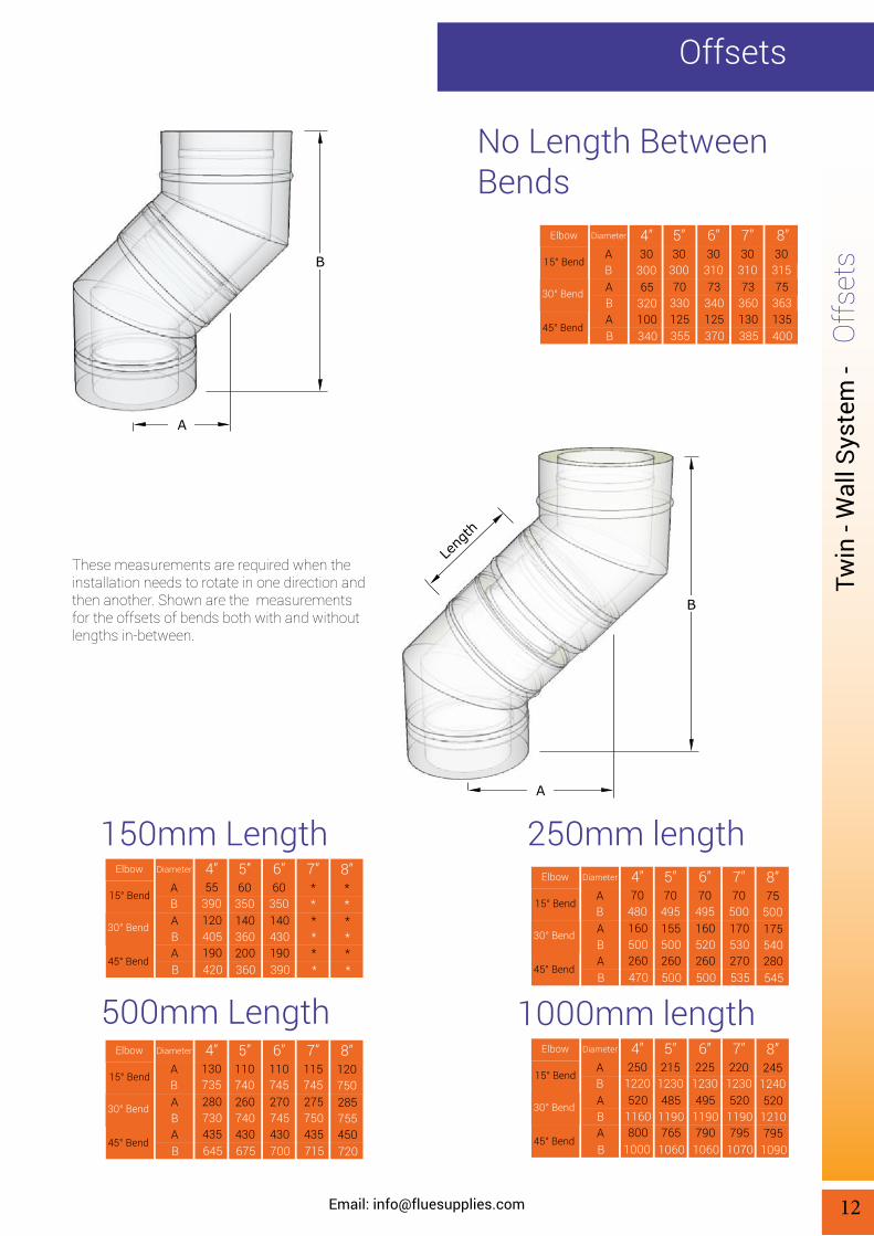
No Length Between Bends
A
B
A
B
Length
30310
7”30
300
5”30
310
6”30
315
8”
7370 73 75
DiameterElbow
360130
330125
340125
363135
385355 370 400
ABABAB
15° Bend
30° Bend
45° Bend
These measurements are required when the installation needs to rotate in one direction and then another. Shown are the measurements for the offsets of bends both with and without lengths in-between.
150mm Length
*
250mm length
500mm Length 1000mm length
Offsets
**
7”60
350
5”60
350
6”
*140 140
DiameterElbow
**
360200
430190
*360 390
ABABAB
15° Bend
30° Bend
45° Bend
55390
4”
120405190420
**
8”
****
115745
7”110740
5”110745
6”
275260 270
DiameterElbow
750435
740430
745430
715675 700
ABABAB
15° Bend
30° Bend
45° Bend
130735
4”
280730435645
120750
8”
285755450720
70500
7”70
495
5”70
495
6”
170155 160
DiameterElbow
530270
500260
520260
535500 500
ABABAB
15° Bend
30° Bend
45° Bend
70480
4”
160500260470
75500
8”
175540280545
2201230
7”215
1230
5”225
1230
6”
520485 495
DiameterElbow
1190795
1190765
1190790
10701060 1060
ABABAB
15° Bend
30° Bend
45° Bend
2501220
4”
5201160800
1000
2451240
8”
5201210795
1090
30300
4”
65320100340

Twin
- W
all s
yste
m -
Contact our sales Team: Telephone: 0844 800 6586 Fax: 01622 711 418
40
D
D
B
110
A
40
110
C
100 - 300mm
A
A
3040
A
B
Base Support
Supp
ort C
ompo
nent
s
Used for additional support at the base of the external installation.
13
Adjustable 60 - 100mm
Wall SupportUsed for additional support at any point of the external installation.
Adjustable 22.5 - 75mm
Roof BracingUsed to attach to the roof rafters for additional support.
Adjustable
Diameter (mm) 180External (mm) 230
7”130180
5”150200
6”200250
8”250300
10”300350
12”350400
14”
A (mm)B (mm)
370189
322189
340189
385189
N/AN/A
N/AN/A
N/AN/A
Diameter (mm) 180External A (mm) 230
7”130180
5”150200
6”200250
8”250300
10”300350
12”350400
14”
B (mm)C (mm)
275355
225305
245325
295375
345425
395475
445525
Support Components
D (mm) 295265 265 310 360 410 460
Ceiling HangerUsed to attach to the ceiling for additional support.
Swivel Ring
Diameter (mm) 180External A (mm) 230
7”130180
5”150200
6”200250
8”250300
10”300350
12”350400
14”100150
4”
Diameter (mm) 180External A (mm) 230
7”130180
5”150200
6”200250
8”250300
10”300350
12”350400
14”100150
4”
100150
4”
215295235
100150
4”
310189

Twin
- W
all s
yste
m -
Email: [email protected]
Supp
ort C
ompo
nent
s
14
Roof Support
Guy Wire Bracket
Roof Stabilizer
Used to attach to the roof rafters for additional support.
Used in conjunction with Guy Wire (not supplied) to support the run of the twin-wall if it is over 1.5mtrs above the roof. Also may be used in conjunction with rigid angle iron stays (not supplied).
Used to support the run of the twin-wall if it is over 1.5mtrs above the roof.
Bracket 1 - 2 Metre
150
250
A
A
40
A
Diameter (mm) 180External A (mm) 230
7”130180
5”150200
6”200250
8”250300
10”300350
12”350400
14”100150
4”
Diameter (mm) 180External A (mm) 230
7”130180
5”150200
6”200250
8”250300
10”300350
12”350400
14”100150
4”
Diameter (mm) 180External A (mm) 230
7”130180
5”150200
6”200250
8”250300
10”300350
12”350400
14”100150
4”

Twin
- W
all s
yste
m -
Contact our sales Team: Telephone: 0844 800 6586 Fax: 01622 711 418
Firestop Spacer
Fire
stop
Spa
cers Used when the upper section of the system is open.
Used on oil and gas installations where the flue gas temperature does not exceed 250°C or for solid fuel when passing through a non combustible ceiling.
15
Firestop SpacerFor use when going through a floor or ceiling at an angle. Available in 0 - 30° and 31 - 45°.
Split
Firestop SpacerUsed for enclosed upper sections to allow air ventila-tion.
Vented
Firestop Spacers
Split Firestop SpacerVented
Diameter 180237
7”130182
5”150207
6”200257
8”250307
10”300357
12”350407
14”
B (mm) 390390 390 533 603 653 703A (mm)
For use when going through a floor or ceiling at an angle. Available in 0 - 30° and 31 - 45°.
100157
4”
453
Diameter 180238
7”130188
5”150208
6”200258
8”250308
10”300358
12”350408
14”
B (mm) 430375 400 450 500 550 600A (mm)
100158
4”
350
A
B
B
B
AC
B
A
90
C
B
A
Diameter 180230
7”130180
5”150200
6”200250
8”250N/A
10”300N/A
12”350N/A
14”
300290 280 340 N/A N/A N/AA (mm)
C (mm) 545475 500 545 N/A N/A N/AB (mm)
100150
4”
285450
Diameter 180230
7”130180
5”150200
6”200250
8”250N/A
10”300N/A
12”350N/A
14”
300290 280 340 N/A N/A N/AA (mm)
C (mm) 545475 500 545 N/A N/A N/AB (mm)
130150
4”
285450

Twin
- W
all s
yste
m -
Email: [email protected]
Supp
orts
& T
rims
16
Ceiling Supports & Trims
A
B
A
B
A
A
B
B
45° Trim CollarUsed to neaten the installation holes in both walls and ceilings.
90° Trim CollarUsed to neaten the installation holes in both walls and ceilings.
Round
Ceiling/FloorCeiling supports are load bearing and come with sup-port collar. Used on oil and gas installations where the flue gas temperature does not exceed 250°C or for solid fuel when passing through a non combustible floor/ceil-ing.
Support
Vented Ceiling/FloorSupport
Diameter 180N/A
7”130187
5”150207
6”200N/A
8”250N/A
10”300N/A
12”350N/A
14”
B (mm) N/A90 90 N/A N/A N/A N/AA (mm)
Ceiling supports are load bearing and come with support collar.
Oval
Diameter 180N/A
7”130187
5”150207
6”200N/A
8”250N/A
10”300N/A
12”350N/A
14”
B (mm) N/A90 90 N/A N/A N/A N/AA (mm)
Diameter 180238
7”130188
5”150208
6”200258
8”250308
10”300358
12”350408
14”
B (mm) 430375 400 450 500 550 600A (mm)
100158
4”
350
Diameter 180238
7”130188
5”150208
6”200258
8”250308
10”300358
12”350408
14”
B (mm) 430375 400 450 500 550 600A (mm)
100158
4”
350

Twin
- W
all s
yste
m -
Contact our sales Team: Telephone: 0844 800 6586 Fax: 01622 711 418
Wall Band
Wal
l Bra
cket
s Used to provide lateral support for a twin -wall system can be used for internal and external walls.
17
Wall BandAdjustable 50mm - 150mm
Wall BandAdjustable 150mm - 250mm
Wall Brackets
Wall BandAdjustable 250mm - 350mm
Adjustable 50mm - 75mm
A
B
C
50-150m
m
B
C
A
150-250m
m
B250-
350mm
C
A
A
50-75mm
Used to provide lateral support for a twin -wall system can be used for internal and external walls.
Used to provide lateral support for a twin -wall system can be used for internal and external walls.
Used to provide lateral support for a twin -wall system can be used for internal and external walls.
Diameter (mm) 180External A (mm) 230
7”130180
5”150200
6”200250
8”250300
10”300350
12”350400
14”100150
4”
Diameter 180230
7”130180
5”150200
6”200250
8”250300
10”300350
12”350400
14”
340285 310 360 410 460 510A (mm)
C (mm) 265225 265 265 265 325 325B (mm)
100150
4”
260225
Diameter 180230
7”130180
5”150200
6”200250
8”250300
10”300350
12”350400
14”
340285 310 360 410 460 510A (mm)
C (mm) 365325 365 365 425 425 425B (mm)
100150
4”
260325
Diameter 180230
7”130180
5”150200
6”200250
8”250300
10”300350
12”350400
14”
340285 310 360 410 460 510A (mm)
C (mm) 465425 465 465 525 525 525B (mm)
100150
4”
260425

Twin
- W
all s
yste
m -
Email: [email protected]
Lead
Fla
shin
g &
Colla
r
18
Lead Flashing & Collar
B
A 30
A
B
A B
A B
Diameter 180230
7”130180
5”150200
6”200250
8”250300
10”300350
12”350400
14”
B (mm) 360305 330 380 430 480 530A (mm)
Storm CollarStorm collars deflect rain from the top of the lead flashing. Seal with silicone sealant.
Flat Flashing 0 - 5°The lead-based flashings (with stainless steel upstand) act as weatherproofing for the twin-wall system when used externally through a roof.
Roof Flashing 5 - 25°The lead-based flashings (with stainless steel upstand) act as weatherproofing for the twin-wall system when used externally through a roof.
Roof Flashing 25 - 45°The lead-based flashings (with stainless steel upstand) act as weatherproofing for the twin-wall system when used externally through a roof.
100150
4”
280
Diameter 180610
7”130760
5”150760
6”200610
8”250N/A
10”300N/A
12”350N/A
14”
B (mm) 610760 760 610 N/A N/A N/AA (mm)
100760
4”
760
Diameter 180760
7”130760
5”150760
6”200610
8”250300
10”300350
12”350400
14”
B (mm) 10001000 1000 630 500 550 600A (mm)
100760
4”
1000
Diameter 180760
7”130760
5”150760
6”200760
8”250N/A
10”300N/A
12”350N/A
14”
B (mm) 10001000 1000 1000 N/A N/A N/AA (mm)
100760
4”
1000

Twin
- W
all s
yste
m -
Contact our sales Team: Telephone: 0844 800 6586 Fax: 01622 711 418
All Weather Cowl
Term
inal
s
These terminals are especially designed to fit the Jer-emias twin - wall system providing protection against rain and other elements.
19
Adaptor To Colt CowlFor Mini Rotorvent
Rain Cap
Terminals
Top Stub
Used to close off the insulation at the top of the system and connect to a mini rota vent.
These terminals are especially designed to fit the Jer-emias twin - wall system providing protection against rain and other elements.
The top stub will close off the insulation at the top of the system and converts the size back to the internal diameter.
Diameter 180350
7”130300
5”150345
6”200400
8”250N/A
10”300N/A
12”350N/A
14”
275225 215 275 N/A N/A N/AA (mm)
C (mm) 155110 110 110 N/A N/A N/AB (mm)
B
A
A
C
B
B
A
80 100
80
100
A
(Locking bands are NOT provided with these components)
M6 Bolts Required (Not supplied with Unit).
Diameter (mm) 180External A (mm) 230
7”130180
5”150200
6”200250
8”250300
10”300350
12”350400
14”100150
4”
Diameter (mm) 180External A (mm) 230
7”130180
5”150200
6”200250
8”250300
10”300350
12”350400
14”100150
4”
Diameter 180A (mm) 360
7”125260
5”150300
6”200400
8”250N/A
10”300N/A
12”350N/A
14”
B (mm) 310265 285 320 N/A N/A N/A
100200
4”
240
100275
4”
225110

Twin
- W
all s
yste
m -
Email: [email protected]
Term
inal
s
20
With adaptorDraught StabilizerThe adaptor fits into the branch of the Twin Wall In-sulated 90 deg Tee, It is used to control excess draft for oil/solid fuel/biomass.
C
B
A
B
A
A
B
45° Wall SleeveDesigned to go through the wall at an angle to sheild the twin-wall against coming into contact with com-bustible material.
90° Wall SleeveWall Sleeve designed to go straight through the wall to sheild the twin-wall against coming into contact with combustible material.
(Locking bands are NOT provided with these components)
Diameter 180135
7”130135
5”150135
6”200135
8”250N/A
10”300N/A
12”350N/A
14”
180180 180 180 N/A N/A N/AA (mm)
C (mm) 145183 165 135 N/A N/A N/AB (mm)
100135
4”
180175
Diameter 180250
7”130210
5”150230
6”200270
8”250N/A
10”300N/A
12”350N/A
14”
350350 350 350 N/A N/A N/AA (mm)B (mm)
100180
4”
400
Diameter 180250
7”130210
5”150230
6”200270
8”250N/A
10”300N/A
12”350N/A
14”
500500 500 500 N/A N/A N/AA (mm)B (mm)
100180
4”
500

Twin
- W
all s
yste
m -
Contact our sales Team: Telephone: 0844 800 6586 Fax: 01622 711 41821
Acce
ssor
ies
Accessories
Ventilation ShieldThis simple telescopic tube enables you to install your twin - wall system closer to your rafters when your flue system passes through ceiling - floor sections.
Diameter (mm) 180250
7”130195
5”150220
6”200N/A
8”250N/A
10”300N/A
12”350N/A
14”
250250 250 N/A N/A N/A N/AA (mm)
C (mm) 470470 470 N/A N/A N/A N/AB (mm)
Condensing SealUsed on condensing systems
B
A
C
Quick LockUsed as a quick release and quick lock for twin wall systems.
Locking Band
Diameter (mm) 1807”
1305”
1506”
2008”
25010”
30012”
35014”
1004”
Diameter (mm) 2307”
1805”
2006”
2508”
30010”
35012”
40014”
1504”
100165
4”
250470

Flue supplies, Unit 6-7, Link 20, Bellingham Way, Aylesford, Kent, ME20 7HDTel: 0844 800 6586 Fax: 01622 711418 Email: [email protected]
Copyright 2015 Flue supplies ©
iso 9001Fs 576960


![diagram 5.1 [Converted] - Building Control NI · part of the flue serving an open-flued appliance. flue soot door debris collection space chimney appliance flue outlet appliance flue](https://static.fdocuments.us/doc/165x107/60ea4a68722f9641f22c1939/diagram-51-converted-building-control-ni-part-of-the-flue-serving-an-open-flued.jpg)


