
Twin Screw Pumps - All Pumps Sales & Service · PDF file · 2015-11-25Where...
16
W h e r e I n n o v a t i o n F l o w s S Series Twin Screw Pumps www.maag.com IOM Installation Operation Maintenance Manual MAAG–14000-E-02EMEA REPLACES MAAG-14000-E-02
Transcript of Twin Screw Pumps - All Pumps Sales & Service · PDF file · 2015-11-25Where...

W h e r e I n n o v a t i o n F l o w s
S SeriesTwin Screw Pumps
www.maag.com
IOMInstallationOperationMaintenanceManual
MAAG–14000-E-02EMEA REPLACES MAAG-14000-E-02

S E C T I O N X
TA B L E O F C O N T E N T S
SECTION 1 INTRODUCTION 1
FOREWORD 1
PUMP FUNCTIONALITY 1
SAFETY PRECAUTIONS 1
PRODUCT WARRANTY 2
SECTION 2 RECEIVING, HANDLING & STORAGE 3
RECEIVING 3
LOADING AND UNLOADING 3
STORAGE AND PRESERVATION 3
SECTION 3 INSTALLATION 4
LOCATION 4
FOUNDATION 4
PIPING SYSTEM 5
PIPING SYSTEM ACCESSORIES 5
COUPLING ALIGNMENT 5
DOWELING 6
LUBRICATION 6
LUBRICATING GREASE 6
SECTION 4 OPERATION 7
PUMP PREPARATIONS 7
STARTING THE PUMP 7
RUNNING THE PUMP 7
STOPPING THE PUMP 7
SECTION 5 TROUBLESHOOTING 8
SECTION 6 ROUTINE & PREVENTIVE MAINTENANCE 9
DAILY MAINTENANCE 9
WEEKLY MAINTENANCE 9
QUARTERLY MAINTENANCE 9
ANNUAL MAINTENANCE 9

MAAG-14000-E-02EMEA 1 S SERIES TWIN SCREW PUMPS
S E C T I O N 1
I N T R O D U C T I O N
FOREWORDThis manual is intended to assist those who are involved with the installation, operation and maintenance of a Maag S Series Pump These instructions must be thoroughly reviewed in their entirety and fully understood prior to pump installation, operation or maintenance Special attention should be given to pump lubrication, heating, cooling and sealing during pump installation, operation and maintenance
Maag S Series Pumps include 2H, 2HE, 2HM, 2HR, 2HC, 2HH, 2MPS, 2VE and 2VM models
PUMP FUNCTIONALITY Maag S Series Pumps are rotary, positive displacement pumps capable of handing various clean liquids containing no solids The pump is composed of two opposing sets of screws During pump operation, the screws located on the two shafts are engaged and therein form a sealed cavity with the surrounding pump casing The pumped liquid is displaced axially as the screw shaft turns steadily and constantly, allowing liquid to flow to the center of the pump where the discharge port is located Hydraulic force on the two screws is both opposite and equal, allowing for hydraulic axial stress on the screw shafts to be automatically balanced
The pump’s suction opening for liquid is designed to ensure the flow velocity changes constantly, resulting in reduced entrance friction The smaller the pump’s NPSH, the higher the pump’s suction-lift capability The unique construction (side-inlet and side-outlet; side-inlet and up-outlet; shaft inlet and up-outlet) allows the storage of liquid while the pump is not operating and allows the pump to be in a self-priming state
The pressure-limited valve protects the pump from excessive pressure increases The valve is actuated at a pressure of approximately 1 5 bar (21 8 psi) above the maximum differential pressure and allows the medium to flow back to the intake chamber The pressure-limited valve cannot be used for capacity or pressure control This valve is suitable for single-direction rotation pumps; otherwise, special valves should be used for double-operation pumps
Separate screw-shaft construction is adaptable according to pump application intentions The shafts are made of high-strength alloy steel for greater strength while subject to higher power and torque requirements Various screw-material options are available in order to meet any special application requirements
Separately lubricated timing gears are used to transmit power from the driving shaft to the idler shaft and to prevent metal contact between the meshed, rotating screws, thereby increasing the life expectancy of both the screws and shafts
SAFETY PRECAUTIONSThis manual contains basic references that are to be observed during pump transportation, installation, operation and maintenance, and, therefore, should be kept as part of the permanent pump records and readily accessible as a reference to any person working or maintaining the pumping unit
The instructions within this manual must be thoroughly reviewed in their entirety and fully understood prior to pump installation, operation or maintenance care
These pumps have been designed for safe and reliable operation when properly used and maintained in accordance with the instructions contained within this manual A pump is a pressure-containing device with rotating parts that can be hazardous Failure to read and comply with installation, operation and maintenance instructions will void the responsibility of the manufacturer and may result in bodily injury or equipment damage
NOTE: In addition to the Safety Precautions identified in this section, special safety information is included within later chapters where appropriate
Markings and Instructions on Pump Unit
Direct instructional references regarding direction of rotation, fluid-flow orientation, safety warning, etc , are clearly marked on the pump Please observe and follow all indicated safety markings and instructions
NOTE: Failure to observe safety references can result in the following dangers:
• Equipment failure• Maintenance and service policies voided• Environmental pollution due to hazardous substance leakage• Personal endangerment as a result of electrical, mechanical
and chemical influences
Qualified Personnel & Training
All persons installing, operating, maintaining and inspecting the pumping unit must have the required qualifications for work to be performed All instructions and safety markings must be observed, understood and adhered to by all personnel working on or around the pumping unit If installation or operational knowledge is inadequate, training must be provided The scope of the personal responsibilities, competency and supervisory duties must be closely controlled by the purchaser of the pumping unit
Safety References for Customers
All work performed on or around the pumping unit must be completed by qualified personnel
• Machine components that are either hot or cold must be protected on-site to prevent personal endangerment
• Safety markings on the pumping unit must not be removed from the machine while the pump is running
• Leakage of hazardous media (i e , toxic, flammable, explosive, etc ) must be collected in a way that no damage to personnel or environment occurs

S SERIES TWIN SCREW PUMPS 2 MAAG-14000-E-02EMEA
S E C T I O N X
I N T R O D U C T I O N
• If the pumped media is explosive, toxic or flammable, a warning or alarm device must be installed, pump housing must be well ventilated and the operating site must be a no smoke/fire zone
• To prevent damage due to electricity, all electrical devices must be safely protected, functional and controlled
Pump must meet specified operating parameters
Unless there is written permission by Maag, the pump must not be operated at higher parameters than specified Adhering to these specifications is meant to prevent danger to persons and damage to equipment
Pump Monitoring
Suitable measuring devices must be installed to inspect and control the pump during operation Generally, pressure gauges are to be installed on suction and discharge lines near the pump
NOTE: A pipe safety valve is required in the discharge pipe ofthe pump
PRODUCT WARRANTYOur warranty for shortcomings in the supply is laid down in our delivery conditions No liability will be undertaken for damages caused by non-compliance with the operating instructions and service conditions If, at a later date, the operating conditions change (e g , different fluid conveyed, speed, viscosity, temperature or supply conditions), the pump must be checked by a manufacturer’s representative and acted upon on a case-by-case basis and determination will be made if the pump is suited for the current application use
Prior to leaving our factory, all pumps are subjected to a thorough test run and performance test on a test stand Only properly operating pumps, achieving the pump’s specified performance and assured by Maag, will leave the factory Therein, compliance with the following operating instructions ensures safe operation and delivery

MAAG-14000-E-02EMEA 3 S SERIES TWIN SCREW PUMPS
S E C T I O N 2
R E C E I V I N G , H A N D L I N G & S T O R A G E
RECEIVINGPlace equipment in a controlled environment upon receipt.
Ordinary packing crates for the pump are not suitable to withstand outdoor storage conditions beyond a 30-day limit from date of delivery, not withstanding favorable/unfavorable outdoor conditions Improper storage can damage the equipment, thus voiding product warranty
Special long-term storage packing can be supplied by Maag upon request.
It is at the client’s discretion to observe and relate the packing and storage requirements in the Technological Agreement with Maag
Parts and quality checkpoint.
Upon receipt of shipment, carefully check the pump, driver, spare parts, accessories and documentation in accordance with the supplied Packing List to ensure no components are missing or damaged The identity of any missing or damaged components must be communicated to the carrier and Maag Damage claims should be made at the time of the receipt and check
LOADING AND UNLOADINGSTEP 1For transportation purposes, use suitable lifting tools and attach lifting hooks to places marked on packing Strictly observe applicable safety regulations for lifting heavy loads
NOTE: Do not lift pump by bearing housing
STEP 2When lifting the pump, attach lifting hooks to outlet flangesas seen in Figure 1
STEP 3When lifting the pumping unit (motor included), chain should be attached to the hook of the base-plate Make sure that no pipes or attached auxiliaries are damaged See Figure 2 for reference
STORAGE AND PRESERVATION
Pump units are affixed to the skids on the inside of the packing crates in order to help prevent damage from standard loading and unloading All pump openings are covered with blank flanges or special protective caps to keep pump cavity clean and free of debris
If pump is not to be installed or operated immediately, or if pump is to be installed, but not operated immediately, the pump units must be preserved as indicated below:
STEP 1Store in a clean and dry location
STEP 2Apply a layer of grease to all internal parts of the pump
STEP 3Ensure blank flanges or special protective caps covering pump openings are properly attached
STEP 4Coat preservatives on all exposed shaft elements and places that are not protected by paint
STEP 5Cover the pump and driver with plastic or waterproof canvas FIGURE 1 PUMP LIFTING
S SERIES TWIN SCREW PUMPS 4 MAAG-14000-E-02EMEA
S E C T I O N 3
I N S TA L L AT I O N
The following installation instructions are to assist in the proper pump installation Trouble-free operation of a pump begins with proper installation practices and will also extend the life of your pump Should any questions arise during the installation process, please contact the Maag Service Department for assistance
LOCATIONThe pump has been built to meet the requirements of a specific capacity at a specific pressure To meet these requirements, consideration must be taken regarding the suction and discharge sides of the pump during installation This information must be provided to Maag engineers by the purchaser and specified according to the pre-planned location of the pump installation site If, after receipt, the location of the pump is changed and these pre-planned conditions are altered, please consult Maag engi-neers immediately to ensure safe operation of the pump
An appropriate amount of space must be kept for laying the pump foundation This is a critical pre-condition for pump assembly and disassembly, installation, operation and maintenance
It is suggested to locate the pump as close as possible to the source of the media supply Ideally, the pump location should be clean and dry with enough space to perform the installation, maintenance and preservation
NOTE: If it is necessary to install the pump in a pit or cavity, measurements must be taken and considered in an effort to prevent flooding or any other foreseeable challenge to the instal-lation, maintenance or preservation of the pump
FOUNDATIONGround foundation should be suitable to absorb vibration and provide rigid support for the entire pump unit Generally, rein-forced concrete is used as a foundation material
The required area of the pump location and the location of anchor (foundation) bolts can be defined accordingly to the pump unit outline designation drawing supplied by Maag
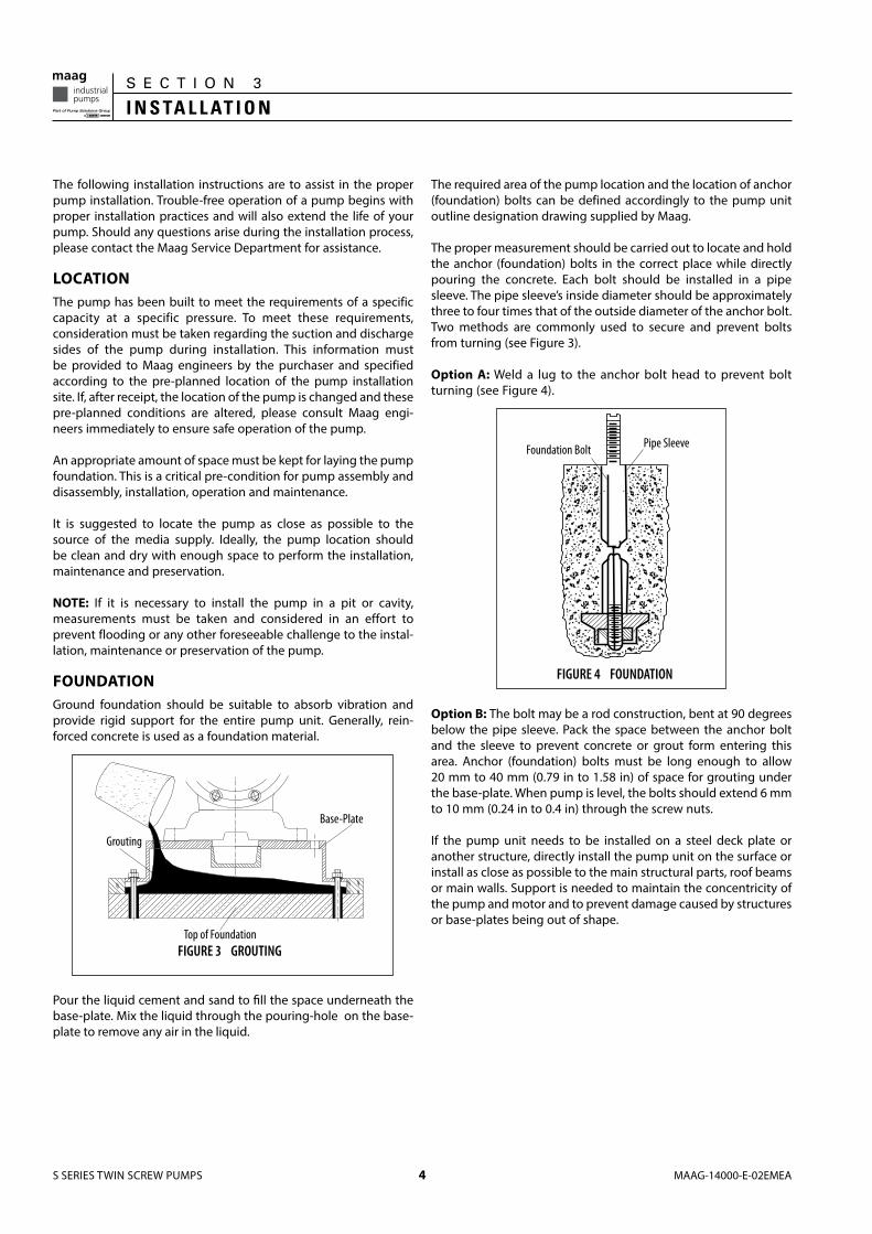
The proper measurement should be carried out to locate and hold the anchor (foundation) bolts in the correct place while directly pouring the concrete Each bolt should be installed in a pipe sleeve The pipe sleeve’s inside diameter should be approximately three to four times that of the outside diameter of the anchor bolt Two methods are commonly used to secure and prevent bolts from turning (see Figure 3)
Option A: Weld a lug to the anchor bolt head to prevent bolt turning (see Figure 4)
Option B: The bolt may be a rod construction, bent at 90 degrees below the pipe sleeve Pack the space between the anchor bolt and the sleeve to prevent concrete or grout form entering this area Anchor (foundation) bolts must be long enough to allow 20 mm to 40 mm (0 79 in to 1 58 in) of space for grouting under the base-plate When pump is level, the bolts should extend 6 mm to 10 mm (0 24 in to 0 4 in) through the screw nuts
If the pump unit needs to be installed on a steel deck plate or another structure, directly install the pump unit on the surface or install as close as possible to the main structural parts, roof beams or main walls Support is needed to maintain the concentricity of the pump and motor and to prevent damage caused by structures or base-plates being out of shape
Pour the liquid cement and sand to fill the space underneath the base-plate Mix the liquid through the pouring-hole on the base-plate to remove any air in the liquid
FIGURE 3 GROUTINGTop of Foundation
Grouting
Base-Plate
FIGURE 4 FOUNDATION
Pipe SleeveFoundation Bolt

MAAG-14000-E-02EMEA 5 S SERIES TWIN SCREW PUMPS
S E C T I O N X
I N S TA L L AT I O N
PIPING SYSTEMSince the pump’s basic operating parts are designed to be affixed on the two screws, extremely close running clearances exist between the screws and the body; therefore, it is very important to have the piping (especially the suction-side piping) cleaned thoroughly before connecting the piping to the pump flanges
After the pump unit has been installed and secured on its foundation, pipe connections may be installed
NOTE: Please see pump outline drawing for location of all pipe connections, flange sizes and other notes pertinent to piping Pipes should be as short and direct as possible Use long radius elbows to change direction when needed
When laying the suction and discharge piping and other supply lines, there must be at least 1 2 times the overall pump length (without drive unit) in front of the gear casing of the pump
Suction piping must be at least the same size of the inlet diameter; it is acceptable if the suction pipes are one class larger than the inlet For example, if the size of the inlet is 150 mm (6 in), the suction pipes should be 200 mm (8 in) The pipe diameter [length of pipe should be four (4x) times that of the pipe’s diameter] is used to connect the suction pipes and the inlet Discharge piping should be the same size as the diameter of the outlet
All major piping parts, including suction pipes, discharge pipes, valves and strainers, should be supported independently and installed properly to avoid any unnecessary strain on the pump The piping flanges must be properly aligned with the pump flanges To check alignment, insert flange bolts through the pipe and pump flange If bolts are easily moved within the bolt holes and if flange faces are parallel with each other, the piping is properly aligned
If the pump is required to operate with suction lift, the suction piping system must be properly made in relation to the original design
NOTE: NPSHa of suction piping must be larger than pump's NPSHr The pump cannot be expected to overcome deficiencies in the suction piping system, such as narrow/thin runs of suction piping, numerous elbows, valves and excessively high points above pump suction, etc In such cases, cavitation will invariably occur and the pump may not operate at normal capacity
Pump and pump accessories should be kept apart by valves to avoid any force while pressure testing or washing the piping system
PIPING SYSTEM ACCESSORIESSUCTION STRAINERS
Maag suggests that suction strainers be installed on the suction side of the pump at least temporarily until the new system is deemed clean of solid residue The screen area of the strainer should be as large as possible Generally, the strainer screen should be constructed of 40 meshes, and 20 or 10 meshes for high-viscosity
applications The net screen area should be approximately 5 to 8 times the flow cross-sectional area of the suction pipe However, if the viscosity of the media is in excess of 200 mm2/s, then approximately 10 to 20 times the pipe cross-sectional area is suggested for the net screen area The maximum differential pressure is 0 1 bar (1 5 psi) The strainer on the suction side can be used to prevent solids from entering into the pump and causing damage to certain parts Install pressure gauges on either side of the strainer to indicate when the strainer should be cleaned The installed strainer should be easy to maintain and clean
Generally, strainers can be used on all liquids except for those of an extremely high viscosity In these cases, the strainer cannot be installed, therefore piping and accessory cleaning is mandatory
CHECK VALVE
If the discharge piping system is subject to a high static head and if the fluid handled flows back into the pump cavity when stopping the pump, a check valve should be installed This valve will prevent hydraulic shock acting upon the pump, and most importantly, it allows for separately starting the pump in a parallel connection system
PRESSURE-LIMITED VALVE
Pressure relief valves should be installed between the discharge valve and the discharge flange of the pump in order to protect both the pump and the piping systems The relief valve should match the pressure and capacity of the pump, and can lead the released fluid back to the source of supply As positive displacement pumps, Maag pumps are equipped with a pressure-limited valve to prevent pressure from building up The starting pressure of the pressure-limited valve should be 1 5 bar (21 8 psi) higher than the pump’s rated pressure If the discharge pipe is restricted or shut off, the pressure of the pump will build up rapidly and the pressure-limited valve will be opened However, only when 30% to 50% of fluid is released back to the suction, will the parts of the pump be protected from being badly damaged Therefore, all valves should be kept open while the pump is in operation The pressure-limited valve on the pump cannot be adjusted by capacity or pressure
GAUGES
A suitable meter must be installed to monitor and control the pump while in operation The vacuum gauge and pressure gauge can be separately installed on the inlet and outlet piping near the pump
COUPLING ALIGNMENTCoupling angle deviation, radial deviation and axial clearance should be kept at a minimum in order to prevent noises, vibration and to reduce wear and tear on bearings and couplings
NOTE: Coupling axial clearance, per specifications, should be within 2 mm to 5 mm (0 08 in to 0 2 in ) If using special coupling, please consult with the manufacturer’s regulations
Maag pump aggregate (including driver, base-plate and other accessories) has been aligned (coupling) prior to delivery However,

S SERIES TWIN SCREW PUMPS 6 MAAG-14000-E-02EMEA
S E C T I O N X
I N S TA L L AT I O N
stresses caused by lifting, transporting and pipe connecting can cause minor distortions that will disturb the alignment Therefore, realignment should be done while installing the pump after the following:
Check coupling alignment after the base-plate has been leveled;after the piping is connected, make a final pre-startup coupling alignment check; if the product to be pumped is high in temperature (for the first use), a hot coupling alignment should be made once the pump has reached its operating temperature
The drive should be installed and connected according to the specific instructions provided by the motor manufacturer During installation, please note the connection requirements for the motor and pump The direction of rotation of the motor and pump must be aligned with the arrow indicating the direction of the rotation on the pump
If the pump and drive unit are connected, the pump must be primed with the medium prior to checking the direction of drive rotation
CAUTION: The pump must not run dry, or sealing will be damaged!
DOWELINGAfter the pump unit has been running for approximately one week, the coupling must be checked for possible misalignment caused by pipe strain or temperature strain This check must be made immediately after the pumping unit is shut off, before it has a chance to cool If alignment is correct, the drive must now be doweled on diagonal feet
LUBRICATIONFor all Maag Twin Screw Pumps, lubricating oil and/or lubricating grease are used for lubricating the bearings and gears of the pump (see Figure 5)
LUBRICATING OILGear oil in the gear box is used to lubricate and cool timing gears of the pump and to splash-lubricate roller bearings Maag suggests using the same type of high-grade gear oil with anti-foaming agents, oxidation and corrosion inhibitors, and an abra-sion-resistant agent It is suggested that the gear oil meet the following requirements:
ISO 150 VG
Viscosity at 50°C 80 – 165 cSt
Flash Point 190ºC – 200°C (374ºF – 392ºF)
The general gear oils that Maag suggests using are:Mobil Industrial Gear Oil, No 120#The Great Wall Industrial Gear Oil, No 150#
The frequency at which the gear oil should be replaced:
New Pump Accumulative Total 260 hoursIntermittent Running Accumulative Total 600 -1,200 hoursContinuous Running Accumulative Total 2,200 hours
When the pump is running, the oil level should be maintained at the center of the sight glass, the lowest location should be seeable from the sight glass When the pump is not running, the oil level should not exceed the highest location of the sight glass
LUBRICATING GREASE
Lubricate the double-row angular contact ball bearing by injecting grease into the bearing using an oil gun or an oil canister
NOTE: Under normal operating conditions, apply grease once per 800 accumulated hours
Use the same type of grease for every application If the operating temperature is too high or if the load is too heavy, please consult the manufacturer of the grease that is being used
FIGURE 51 Lubricating Oil Inlet 2 Grease Inlet
21
2

MAAG-14000-E-02EMEA 7 S SERIES TWIN SCREW PUMPS
S E C T I O N 4
O P E R AT I O N
PUMP PREPARATIONS The final pre-startup check is very important to avoid operational difficulties Listed below are several key components to be checked prior to pump operation:
STEP 1Inspect all piping Check individual piping support; check for leaks and unnecessary piping strain on the pump; flush all piping to ensure removal of foreign material from the system; check that all valves and gauges are functional; check mesh-size suitability
STEP 2 Ensure pump cavity is filled with pump fluid
STEP 3Check that oil is at the proper level in the gear housing Excessive oil will cause the gear box to overheat (see Figure 6)
STEP 4Check pressure gauges and all other meters
STEP 5Check all electrical equipment (i e , cables, control lines and accessories)
If pump is jacketed for heating, heat the pump casing to the prescribed temperature Steam, hot water and hot oil can be used as a heating medium According to the different materials of the pump casing, select proper pressure for heating medium within the limit of 2 0 to 8 0 bar (29 0 to 116 psi) Inlet and outlet are located on the pump casing; therefore, the thermal difference between pumped fluid and heating medium should be as small as possible in order to avoid generating internal stress Especially for cast-iron pumps, the thermal difference between the pumped fluid and the heating medium should be less than 50°C (122ºF)
If the pump is installed with a double mechanical seal, then sealing the liquid system is required The pressure for sealing the liquid system should be 1 0 to 2 0 bar (14 5 to 29 0 psi) higher than that of the pump suction chamber All rules and regulations regarding sealing the liquid system should be adhered to as described in the Sealing Liquid System Instructions
STEP 6Check rotation shafts by rotating the coupling by hand to determine whether the pump shafts and motor shaft turn freely If any rubbing or binding occurs, the cause must be located and corrected before starting the pump
STEP 7Check that motor rotation is correct; refer to the rotation directional mark located on the pump
STARTING THE PUMPSTEP 1Open the suction and discharge valves wide in order to keep the entire piping system unobscured
NOTE: Ensure that all valves and devices on the suction and discharge sides are opened before starting the pump
STEP 2AIf pump is installed with a heating jacket, introduce heating medium and heat the pump to the temperature as described in previous section
STEP 2BIf pump is equipped with double mechanical seals, introduce sealing liquid and monitor the sealing liquid system
STEP 3Rotate the coupling by hand to determine if rubbing or binding occurs
STEP 4Start motor/driver
STEP 5The pump must be stopped if there is no capacity after starting Restart the pump after several minutes If there is still no capacity, the cause must be determined Please refer to the Troubleshooting section of this manual for further instruction
RUNNING THE PUMPSTEP 1Check the pumping unit for unusual noise or vibration Any unusual vibration or change in sound must be investigated and corrected to normal operating conditions
STEP 2Check bearing housing temperature Bearing temperature can safely rise to between 65°C and 75°C (149ºF and 167ºF) Pumped medium or spot environmental temperature should be considered when determining whether temperature exceeds normal operating conditions
Bearing temperature up to 90°C (194ºF) is considered to be normal Within this limit, the stability of the temperature is the best indicator of normal operation A sudden increase in temperature indicates that a bearing problem is developing and the bearing should be checked immediately
CAUTION: Do not attempt to measure the temperature by hand!
STOPPING THE PUMPSTEP 1Stop the motor and pump
STEP 2Close suction and discharge valves
STEP 3If pump is installed with a heating device, stop the heating device first, then close the sealing system after cooling
FIGURE 6 Oil Level of the Gear Casing
max
min

S SERIES TWIN SCREW PUMPS 8 MAAG-14000-E-02EMEA
S E C T I O N 5
T R O U B L E S H O O T I N G
BELOW CAPACITY
NO CAPACITY
EXCESSIVE DRIVER TEMP.
INCREASE IN NOISE OR VIBRATIONS
SHAFT DOES NOT
TURNTROUBLESHOOTING
• No medium is stored within the pump. • Re-introduce the appropriate amount of pumped medium.
• • • Suction pipes leak. • Check all direct connecting pipes between suction pipes and discharge pipes.
• • •Insufficient suction conditions.
• Check piping. If the velocity of flow is too fast, the diameter of the pipes should be enlarged; if the viscosity of the medium is too high, heating measure should be taken.
• Clean the strainer if blocked.
• • •Directional flow in suction piping changes suddenly.
• Valve’s apertures are not functioning properly, and cavitation has most likely occurred. • Completely open valves in order to correct pipeline.
• • Space between screws, screw and casing are enlarged causing wear and tear. • Replace worn parts.
•Large foreign matter or impurities among moving parts.
• Counter-rotate pump shafts, remove foreign matter or impurities. • If necessary, disassemble the pump and perform a maintenance check.
•Internal components expand when overheated.
• Rotate pump shafts by hand after cooling down.• Restart pump.
• • •Bearing is broken or there is a lack of oil in gear housing.
• Disassemble the pump to replace broken bearing when it is necessary.• Add gear oil per instructions previously described within this manual.
• Incorrect direction of rotation. • Reverse the directional rotation of the driver.
• • • Incorrect coupling alignment. • Realign coupling.
•The pump revolving speed (N) is too low.
• Check motor.• Determine cause of low motor speed. Refer to manufacturer’s instructions to increase revolving speed.
• • Discharge pressure is greater than operating pressure of pump, and the recycle valve has opened. • Decrease discharge pressure.
• • Mechanical seals leak. • Check and replace mechanical seal.

MAAG-14000-E-02EMEA 9 S SERIES TWIN SCREW PUMPS
S E C T I O N 6
R O U T I N E & P R E V E N T I V E M A I N T E N A N C E
For special or custom pumps, please refer to the maintenance instructions within this manual
DAILY MAINTENANCESTEP 1Check oil level in gear box If necessary, disassemble screw plug from the top of the gear box and apply oil to the center of the sight glass
STEP 2Listen for unusual noise or vibration
STEP 3Inspect pump shaft seal for leaks when pump is running Regarding mechanical seal installation, product vaporizes resulting in no observable leakage; however, for some applications, a modest amount [3 mL/h (0 10 oz/h) to 5 mL/h (0 17 oz/h)] of leakage is acceptable
Coupling/Special Coupling: Please refer to Manufacturer’s Special Instructions in the Appendix
Driver: Please refer to Manufacturer’s Special Instructions in the Appendix
Special Accessories: If pump is provided with special accessories, for instructions regarding the maintenance of these accessories, please refer to Manufacturer’s Special Instructions in the Appendix
WEEKLY MAINTENANCESTEP 1If pump is not in use for one week, open suction and discharge valves, run idle pump under power
STEP 2Check operation of suction and discharge valves
QUARTERLY MAINTENANCESTEP 1Check all foundation bolts, screws and hold-down bolts for tightness
STEP 2Change oil as previously described in this manual Turn open draining screw plug of the gear housing, disassemble oil-input screw plug and inject clean, light oil into resin gear box Tighten screw plug, inject gear oil to the level of the sight glass and tighten oil-input screw plug Add grease for fore-bearing housing as previously described in this manual
ANNUAL MAINTENANCESTEP 1Check coupling alignment
STEP 2Check existing pump capacity, pressure and power against pump and motor nameplate data If pressure and capacity have decreased excessively, the pump should be disassembled and worn parts should be replaced However, if pump performance is satisfactory, disassembly for inspection is not required

S E C T I O N X
N O T E S

S E C T I O N X
N O T E S

S E C T I O N X
N O T E S

S E C T I O N X
W A R R A N T Y
Item # Serial #
Company Where Purchased
Company Name
Industry
Name Title
Street Address
City State Postal Code Country
Telephone Fax Email Web Address
Number of pumps in facility? Number of Maag pumps?
Types of pumps in facility (check all that apply): Diaphragm Centrifugal Gear Submersible Lobe
Other
Media being pumped?
How did you hear of Maag Pump? Trade Journal Trade Show Internet/Email Distributor
Other
P U M P I N F O R M AT I O N
PLEASE PRINT OR TYPE AND FAX OR EMAIL TO MAAG
Maag, a Dover Company, warrants its products free from defects in materials and workmanship under normal use and service for which its products were designed. This warranty is for a period of 12 months after installation or 18 months after shipment from the factory, whichever comes first. This standard warranty applies unless specific warranty conditions are granted in writing by Maag. If its products should fail through defect in workmanship or material within the stated warranty period, Maag must be notified in writing within the warranty period of such defects and shall have the option of requiring return of parts or product to its factory for verification of any claim. The warranty is in lieu of any other liability for defects.
MAAG MAKES NO WARRANTY OF MERCHANTABILITY AND NO WARRANTY THAT ITS PRODUCTS SHALL BE APPROPRIATE FOR ANY PARTICULAR PURPOSE, nor are there any other warranties, expressed or implied, by operation of law or otherwise. This warranty does not cover any expense (labor, lost production, travel expenses, etc.), incurred in repairs or alteration made outside the Maag factory without prior authorization, nor does it cover in any way the performance of equipment which has been revised or altered by others. The customer is wholly responsible for establishing the suitability of the product for his particular application and for operating conditions, which do not exceed published product limitations. Maag shall not be liable for damages or delay resulting from or related to defective products, nor for consequential, special or contingent damages for breach of warranty.
YO U R I N F O R M AT I O N
ONCE COMPLETE, FAX TO +41 44 278 82 01 OR EMAIL TO [email protected]

PSG reserves the right to modify the information and illustrations contained in this document without prior notice. This is a non-contractual document. 07-2014
Where Innovation Flows
Aspstrasse 128154 Oberglatt Switzerland
O: +41 44 278 82 00F: +41 44 278 82 01www.maag.com
Copyright ©2014, Pump Solutions Group (PSG), A Dover Company
A u t h o r i z e d P S G R e p r e s e n t a t i v e :


![NORTA MIT PRESENTATION.pptx [Read-Only] · • Centrifugal pumps • Side channel pumps • Gear pumps • Screw pumps • Single screw pumps • Piston pumps • Vacuum pumps •](https://static.fdocuments.us/doc/165x107/5ec27ab9e3ef591d10504c3a/norta-mit-read-only-a-centrifugal-pumps-a-side-channel-pumps-a-gear-pumps.jpg)