TWiLiTE WB-57 Aircraft Etalon Qualification LIDAR Working Group Welches, OR June 28, 2006 1 Michigan...
24
TWiLiTE WB-57 Aircraft Etalon Qualification LIDAR Working Group Welches, OR June 28, 2006 1 Michigan Aerospace Corporation 2 NASA Goddard Space Flight Center Authors: 1 Michael Dehring, 1 Scott Lindemann & 2 Bruce Gentry
-
Upload
junior-barrett -
Category
Documents
-
view
213 -
download
0
Transcript of TWiLiTE WB-57 Aircraft Etalon Qualification LIDAR Working Group Welches, OR June 28, 2006 1 Michigan...
TWiLiTE WB-57 Aircraft Etalon Qualification
LIDAR Working GroupWelches, OR June 28, 2006
1Michigan Aerospace Corporation
2NASA Goddard Space Flight Center
Authors: 1Michael Dehring, 1Scott Lindemann & 2Bruce Gentry

Discussion Outline
• Project description and overview of goals
• Etalon specifications and design strategy
• Vibration power spectrum inputs
• Test Set-Up and Description
• Vibration testing results
• Conclusions
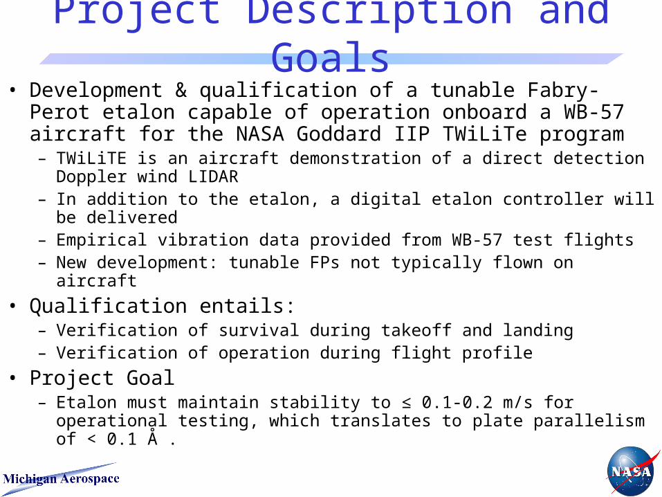
Project Description and Goals• Development & qualification of a tunable Fabry-Perot etalon
capable of operation onboard a WB-57 aircraft for the NASA Goddard IIP TWiLiTe program– TWiLiTE is an aircraft demonstration of a direct detection Doppler wind
LIDAR– In addition to the etalon, a digital etalon controller will be delivered– Empirical vibration data provided from WB-57 test flights– New development: tunable FPs not typically flown on aircraft
• Qualification entails:– Verification of survival during takeoff and landing– Verification of operation during flight profile
• Project Goal – Etalon must maintain stability to ≤ 0.1-0.2 m/s for operational testing,
which translates to plate parallelism of < 0.1 Å .

TWiLiTE Etalon SpecificationsCentral Wavelength 355nm
Plate Spacing 0.90 cm
Free Spectral Range (FSR) 0.555 cm-1 / 16.67 GHz
Reflectivity 0.75
Finesse 10.8
Coated Clear Aperture 5.0 cm
Working Aperture 3 - 24 mm Segments
PZT Dynamic Range 3.1 µm
Etalon Plate Flatness Lambda/15024 mm working CA
Step region boundary
Reference Region
Intermediate step 20.2 nm from reference
Major step70.7 nm from reference
60 mm substrate
24 mm working CA
Step region boundary
Reference Region
Intermediate step 20.2 nm from reference
Major step70.7 nm from reference
60 mm substrate
• Triple Aperture ‘Stepped’ Air-gapped Tunable Etalon– ‘Stepped’ etalon plate creates three
spectrally distinct resonant cavities
• Triple Aperture ‘Stepped’ Air-gapped Tunable Etalon– ‘Stepped’ etalon plate creates three
spectrally distinct resonant cavities

Receiver Technology Overview
Stepped Etalon
• Two Edge Filters and Locking filter generated from stepped sub-apertures of etalon
• Plate parallelism is particularly important since filter positions must remain stable with respect to backscattered lineshape
• Two Edge Filters and Locking filter generated from stepped sub-apertures of etalon
• Plate parallelism is particularly important since filter positions must remain stable with respect to backscattered lineshape
TWiLiTE Receiver

Etalon Full Field Fringe Pattern
Steps in etalon plate were created by vapor deposition of fused silica.
24 mm working CA
Step region boundary
Reference Region
Intermediate step 20.2 nm from reference
Major step70.7 nm from reference
60 mm substrate
24 mm working CA
Step region boundary
Reference Region
Intermediate step 20.2 nm from reference
Major step70.7 nm from reference
60 mm substrate
Note Steps

Etalon Design Strategy
• Take existing space qualified etalon design and ruggedize it for stability in a mechanically dynamic environment– Accomplished through FEA analysis of etalon– Ensured that resonant frequencies are in high
frequency-low power region of anticipated spectrum
• Add vibration isolators to Doppler receiver to dampen the vibration imparted to the etalon– Isolators dampen high frequencies however amplify
low frequencies

Input Power Spectrum for X & Y-Axis Testing
Optical axis of etalon aligned along x-axisOptical axis of etalon aligned along x-axis
x
y
x
Z
X

Input Power Spectrum for Z-Axis Testing
x
y
x
Z
X
Optical axis of etalon aligned along x-axisOptical axis of etalon aligned along x-axis

Transmitted Power to Etalon
Rope isolators shifts power from high frequencies to low.
profile(f)
Lens Holder Z(f): PSDRms=0.015
ETALON Side Z(f): PSDRms=0.016
ETALON Back Z(f): PSDRms=0.018
2000.003.75 10.00 100.00 1000.00
0.0398
3.98E-10
1.00E-09
1.00E-08
1.00E-07
1.00E-06
1.00E-05
0.0001
0.0010
0.0100
Frequency (Hz)
(gn)²/Hz

FEA of Etalon Structure
PSD for the WB-57 indicates resonances are in lower power region of the transmitted spectrum.
Frequency Number Hertz
1 3806
23807.
8
34231.
7
47304.
7
57569.
6
67571.
8
79821.
6
89860.
9
99865.
5
10 10362

FEA of Etalon Structure
PSD for the WB-57 indicates resonances are in lower power region of the transmitted spectrum.
Frequency Number Hertz
1 3920
23920.6
34208.2
44876.6
5 5015
65015.8
76001.4
8 6023
96032.5
106921.9
116928.3
12 7471
137496.1
147505.9
157513.5
168117.6
Three points held fixedrepresenting reference plane defined by mount
Six points held fixed in X and Yaxes while allowed to translatein Z axis, representing diaphragm tabs at top of mount.
Three points held fixedrepresenting reference plane defined by mount
Six points held fixed in X and Yaxes while allowed to translatein Z axis, representing diaphragm tabs at top of mount.

FEA of Etalon StructureFrequency Number Hertz
1 776.42
2 778.96
3 1289.8
4 1479.4
5 1661.3
6 1813.4
7 1864
8 2039.5
9 2344.1
10 2560.1
11 3108.2
12 3248.4
13 3540.4
14 3542.9
15 3932.5
16 4003.9
1813.4 Hz
PSD for the WB-57 indicates resonances are in lower power region of the transmitted spectrum.

Space Versus Aircraft Design• Space qualification purely for survival • Aircraft qualification requires optical operation throughout broadband
vibration spectrum• Mechanical stiffness requirements are far higher for an aircraft
qualified etalon than a spacecraft version– Increased mass over space rated version– Reduced thermal compliance of etalon plates compared to space version
• Space qualification purely for survival • Aircraft qualification requires optical operation throughout broadband
vibration spectrum• Mechanical stiffness requirements are far higher for an aircraft
qualified etalon than a spacecraft version– Increased mass over space rated version– Reduced thermal compliance of etalon plates compared to space version
Space Qualified Design Aircraft Qualified Design
Shortened Spring Arm Increases Stiffness
Lower Center of Gravity
Thickened & Extended Cylinder Wall

Vibration Profile Comparison

Test Setup for Vibration Qualification
Det 2 EM
Det 1Etalon
Graseby 250 Optometer
Signals IN
Etalon Controller
Fiber input
Vibration table
To 16 bit AI board
Fro
m 1
6 bi
t A
O b
oard
He-Cd Laser
FPE
• CW He-Cd 355nm source used to illuminate 1 of etalon sub-apertures
• Si-Diodes used for detectors
• Prior to testing etalon was aligned such that the fringe was illuminated at the HWHH point to achieve max sensitivity
• Sampling rate for vibration testing was 1 KHz
• Prior to each testing sequence, pre-test data was recorded as well as etalon spectral response

Vibration Test Parameters• Input PSD profiles Derived from 3-axis Accelerometer
Data Taken During WB-57 Flight– Accelerometer package located in plane Bomb-bay– Scaled to simulate ‘worst case’ for survival and operation
• Peak amplitude plus 3- at each frequency used for the various PSDs
• Integrated Instrument with Etalon Shaken in Three Orthogonal Axes– Six vibration tests performed in each axis
• Sine sweep from 10-1600 Hz at 0.1 G^2/Hz– Performed before and after PSD testing in each axis
• Survival PSD test for 3 minutes representing take-off conditions– Test performed sequentially at 0.25, 0.5 and full amplitude PSD
• Operational PSD test for 5 minutes

Vibration Qualification Test Setup
Signal Input FiberSignal Output Detector
Etalon Controller Pre-amp Board
Accelerometers
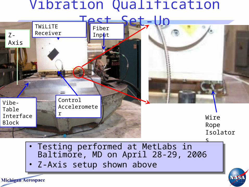
Vibration Qualification Test Set-Up
• Testing performed at MetLabs in Baltimore, MD on April 28-29, 2006
• Z-Axis setup shown above
• Testing performed at MetLabs in Baltimore, MD on April 28-29, 2006
• Z-Axis setup shown above
Wire Rope Isolators
TWiLiTE Receiver
Z-Axis
Vibe-Table Interface Block
Control Accelerometer
Fiber Input

0 50 100 150 200 250 300 3500
1
2
3
4
5
6Z Speed Errors (m/s): Operational, Full, Half, Quarter, Pre
File
m/s
Operational (0.682 grms)Full (2.68 grms)Half (1.34 grms)Quarter (0.67 grms)Pre (0 grms)
Results of Z-Axis Testing

0 50 100 150 200 250 3000
0.5
1
1.5
2
2.5
3X Speed Errors (m/s): Operational, Pre
File
m/s
Operational (1.09 grms)Pre (0 grms)
Results of X-Axis Testing

0 50 100 150 200 250 300 3500
0.5
1
1.5
2
2.5
3
3.5
4Y Speed Errors (m/s): Operational, Pre
File
m/s
Operational (1.09 grms)Pre (0 grms)
Results of Y-Axis Testing

0 50 100 150 200 250 300 3500
0.5
1
1.5
2
2.5
3Z Speed Errors (m/s): Operational, Pre
File
m/s
Operational (0.682 grms)Pre (0 grms)
Results of Z-Axis Testing

Closing Remarks• The etalon vibration testing results for the TWiLiTE project are
encouraging – Represents an important risk reduction to the project as the Fabry-Perot is
the heart of the receiver. • The measured instability of the etalon was ~1- 2 m/s at 1 second
sampling time for the “worse case” operational environment– TWiLiTE will make wind measurements with 10 sec integration times, thus
the expected noise injected from the etalon should drop by SQRT(10) or 3x. – Data reduction is still underway to fully understand the implications of the
results and to ensure analysis was performed properly. • The wind speed errors appear to scale linearly with the magnitude of
vibration• Possible additional noise sources that are being evaluated
– Possible E-M and acoustic interference may have acted as a noise source in the data and skewed the magnitudes higher than realistic
– Final TWiLiTE etalon controller still in development, one used for testing not matched to etalon and may have contributed to slightly higher noise
• Rope isolators are being augmented with additional vibration damping to absorb low frequency power.
• Operation during vibration not a concern for space mission


![The LaserTRACER Calibration and Testing with Sub …volumetric.com.br/anexos/Presentation-Etalon-en 0912[1].pdf · The LaserTRACER The Etalon solution ... the Etalon LaserTRACER is](https://static.fdocuments.us/doc/165x107/5b8aa1707f8b9a9e508b5e6b/the-lasertracer-calibration-and-testing-with-sub-09121pdf-the-lasertracer.jpg)