TutorialandSurveyPaper: Gate ... · PDF fileTutorialandSurveyPaper:...
38
Tutorial and Survey Paper: Gate-Level Test Generation for Sequential Circuits KWANG-TING CHENG University of California, Santa Barbara This paper discusses the gate-level automatic test pattern generation (ATPG) methods and techniques for sequential circuits. The basic concepts, examples, advantages, and limitations of representative methods are reviewed in detail. The relationship between gate-level sequen- tial circuit ATPG and the partial scan design is also discussed. Categories and Subject Descriptors: B.7.3 [Integrated Circuits]: Reliability and Testing— test generation General Terms: Algorithms, Reliability, Verification Additional Key Words and Phrases: Automatic test generation, IC testing, sequential circuit test generation 1. INTRODUCTION The first automatic test pattern generation (ATPG) algorithm for sequen- tial circuits was reported by Seshu and Freeman [1962]. Since then, tremendous progress in the development of algorithms and tools has been made. One of the earliest commercial tools, LASAR [Thomas 1971], was reported in the early seventies, and currently there are more than a dozen sequential circuit test generators commercially available. Due to the high complexity of the sequential circuit test generation problem, it remains a challenging task for these tools to automatically generate high quality tests for large, highly sequential circuits that do not incorporate any design for testability (DfT) scheme. However, these test generators combined with low-overhead DfT techniques such as partial scan have shown a certain success in testing large designs. For designs that are sensitive to area and/or performance overhead, the solution of using sequential circuit ATPG Author’s address: Department of Electrical and Computer Engineering, University of Califor- nia, Santa Barbara, CA 93106. ^[email protected]& Permission to make digital / hard copy of part or all of this work for personal or classroom use is granted without fee provided that the copies are not made or distributed for profit or commercial advantage, the copyright notice, the title of the publication, and its date appear, and notice is given that copying is by permission of the ACM, Inc. To copy otherwise, to republish, to post on servers, or to redistribute to lists, requires prior specific permission and/or a fee. © 1996 ACM 1084-4309/96/1000 –0405 $03.50 ACM Transactions on Design Automation of Electronic Systems, Vol. 1, No. 4, October 1996, Pages 405–442.
Transcript of TutorialandSurveyPaper: Gate ... · PDF fileTutorialandSurveyPaper:...
Tutorial and Survey Paper:Gate-Level Test Generation for SequentialCircuits
KWANG-TING CHENGUniversity of California, Santa Barbara
This paper discusses the gate-level automatic test pattern generation (ATPG) methods andtechniques for sequential circuits. The basic concepts, examples, advantages, and limitationsof representative methods are reviewed in detail. The relationship between gate-level sequen-tial circuit ATPG and the partial scan design is also discussed.
Categories and Subject Descriptors: B.7.3 [Integrated Circuits]: Reliability and Testing—test generation
General Terms: Algorithms, Reliability, Verification
Additional Key Words and Phrases: Automatic test generation, IC testing, sequential circuittest generation
1. INTRODUCTION
The first automatic test pattern generation (ATPG) algorithm for sequen-tial circuits was reported by Seshu and Freeman [1962]. Since then,tremendous progress in the development of algorithms and tools has beenmade. One of the earliest commercial tools, LASAR [Thomas 1971], wasreported in the early seventies, and currently there are more than a dozensequential circuit test generators commercially available. Due to the highcomplexity of the sequential circuit test generation problem, it remains achallenging task for these tools to automatically generate high quality testsfor large, highly sequential circuits that do not incorporate any design fortestability (DfT) scheme. However, these test generators combined withlow-overhead DfT techniques such as partial scan have shown a certainsuccess in testing large designs. For designs that are sensitive to areaand/or performance overhead, the solution of using sequential circuit ATPG
Author’s address: Department of Electrical and Computer Engineering, University of Califor-nia, Santa Barbara, CA 93106. ^[email protected]&Permission to make digital /hard copy of part or all of this work for personal or classroom useis granted without fee provided that the copies are not made or distributed for profit orcommercial advantage, the copyright notice, the title of the publication, and its date appear,and notice is given that copying is by permission of the ACM, Inc. To copy otherwise, torepublish, to post on servers, or to redistribute to lists, requires prior specific permissionand / or a fee.© 1996 ACM 1084-4309/96/1000–0405 $03.50
ACM Transactions on Design Automation of Electronic Systems, Vol. 1, No. 4, October 1996, Pages 405–442.
and partial scan offers an attractive alternative to the popular full-scansolution, which is based on combinational circuit ATPG.It requires a sequence of vectors to detect a single stuck-at fault in a
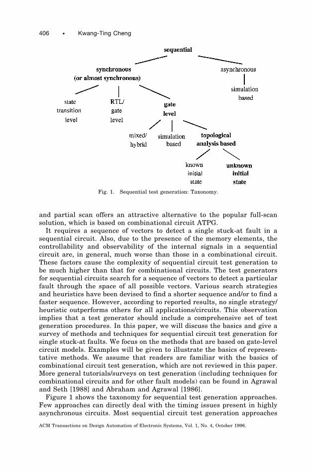
sequential circuit. Also, due to the presence of the memory elements, thecontrollability and observability of the internal signals in a sequentialcircuit are, in general, much worse than those in a combinational circuit.These factors cause the complexity of sequential circuit test generation tobe much higher than that for combinational circuits. The test generatorsfor sequential circuits search for a sequence of vectors to detect a particularfault through the space of all possible vectors. Various search strategiesand heuristics have been devised to find a shorter sequence and/or to find afaster sequence. However, according to reported results, no single strategy/heuristic outperforms others for all applications/circuits. This observationimplies that a test generator should include a comprehensive set of testgeneration procedures. In this paper, we will discuss the basics and give asurvey of methods and techniques for sequential circuit test generation forsingle stuck-at faults. We focus on the methods that are based on gate-levelcircuit models. Examples will be given to illustrate the basics of represen-tative methods. We assume that readers are familiar with the basics ofcombinational circuit test generation, which are not reviewed in this paper.More general tutorials/surveys on test generation (including techniques forcombinational circuits and for other fault models) can be found in Agrawaland Seth [1988] and Abraham and Agrawal [1986].Figure 1 shows the taxonomy for sequential test generation approaches.
Few approaches can directly deal with the timing issues present in highlyasynchronous circuits. Most sequential circuit test generation approaches
Fig. 1. Sequential test generation: Taxonomy.
406 • Kwang-Ting Cheng
ACM Transactions on Design Automation of Electronic Systems, Vol. 1, No. 4, October 1996.
neglect circuit delays during test generation. Such approaches primarilytarget synchronous or almost synchronous (i.e., with some asynchronousreset/clear and/or few asynchronous loops) sequential circuits and cannotproperly handle highly asynchronous circuits whose functions are stronglyrelated to the circuit delays and are sensitive to races and hazards. Oneengineering solution to using such approaches for asynchronous circuits isto divide the test generation process into two phases. A potential test isfirst generated by ignoring the circuit delays. The potential test is thensimulated using proper delay models in the second phase to check itsvalidity. If the potential test is invalid due to races, hazards, or oscillations,test generation is called again for a new potential test. The approaches for(almost) synchronous circuits can be classified according to the level ofabstraction at which the circuit is described. One class of approaches usesthe state transition graph for test generation [Hennie 1964; Hsieh 1971;Cheng and Jou 1992; Pomeranz and Reddy 1991]. This class is suitable forpure controllers for which the state transition graphs are either readilyavailable or easily extractable from a lower-level description. For data-dominated circuits, if both register transfer level (RTL) and gate-leveldescriptions are provided, several approaches can effectively use the RTLdescription for state justification and fault propagation [Hill and Huey1977; Breuer and Friedman 1980; Ghosh 1991]. Most of the commercial testgenerators are based on the gate-level description. They either employ theiterative array model [Kubo 1968; Putzolu and Roth 1971] and use topolog-ical analysis algorithms [Martlett 1978; Cheng 1989; Niermann and Patel1991; Kelsey et al. 1993], or are enhanced from a fault simulator [Snethen1977; Cheng 1989; Saab et al. 1992; Rudnick et al. 1994; Prinetto et al.1994] or use the mixed/hybrid methods that combine the topological-analysis-based methods and the simulation-based methods [Saab et al.1994; Rudnick and Patel 1995; Hsiao et al. 1996]. Most gate-level ap-proaches assume an unknown initial state in the flip-flops, although someapproaches assume a known initial state to avoid initialization of thememory elements [Ma et al. 1988; Ghosh et al. 1991; Cho et al. 1993]. Thehighlighted models and approaches in Figure 1 are those commonlyadopted in most of today’s vendor tools.The paper is organized as follows. In Section 2, we describe the basic
principles of the iterative array model and an in-depth survey of thetopological-analysis-based algorithms. We then discuss the simulation-based methods and the hybrid methods in Section 3. A special class ofapproaches that assumes a known initial state in the flip-flops is discussedin Section 4. In Section 5, the relationship of sequential circuit testgeneration and partial scan is discussed. A brief introduction to theapproaches based on circuit models at higher levels of abstraction is givenin Section 6. We conclude by introducing the concept of functional learningand pointing out the potential of using it to improve the performance androbustness of sequential circuit ATPG.
Gate-Level Test Generation • 407
ACM Transactions on Design Automation of Electronic Systems, Vol. 1, No. 4, October 1996.
2. TOPOLOGICAL-ANALYSIS-BASED APPROACHES
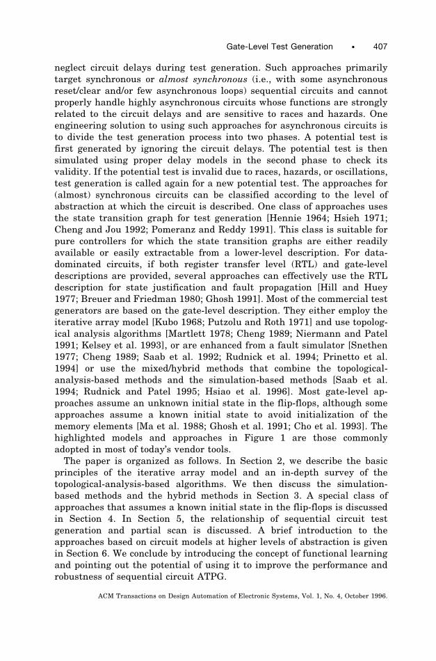
The iterative array model. Many sequential circuit test generators havebeen devised on the basis of fundamental combinational algorithms. Asshown in Figure 2, a combinational model for a sequential circuit isconstructed by regenerating the feedback signals from previous-time copiesof the circuit. A rectangle in Figure 2, called time-frame, represents a copyof the combinational portion of the circuit. The inputs of a time-frameinclude the primary inputs (Ii , i 5 1, . . . , n), and the outputs of theflip-flops, called the present state lines (PSi , i 5 1, . . . , m). The outputs ofa time-frame include the primary outputs (Oi , i 5 1, . . . , k), and the datainputs of the flip-flops, called the next state lines (NSi , i 5 1, . . . , m). Theclock signal is not included in the primary input list in this model. A clockpulse needs to be applied between two time-frames to update the values atthe present state lines of one time-frame from the next state lines of itsprevious time-frame. This combinational model is used to approximate thetiming behavior of the circuit. Topological analysis algorithms that activatefaults and sensitize paths through these multiple copies of the combina-tional circuit are then used to generate tests. Note that a single stuck-atfault in a sequential circuit will correspond to a multiple stuck-at fault inthe iterative array model where each time-frame contains a stuck-at faultat the fault site.
Extended D Algorithm
The earliest algorithms extended the D-algorithm [Roth 1966] for theiterative array model [Kubo 1968; Putzolu and Roth 1971]. It starts withone copy of the combinational logic and sets it to time-frame 0. The
Fig. 2. The iterative-array model of a sequential circuit.
408 • Kwang-Ting Cheng
ACM Transactions on Design Automation of Electronic Systems, Vol. 1, No. 4, October 1996.
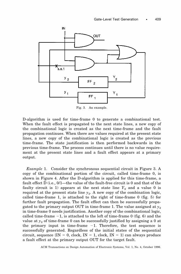
D-algorithm is used for time-frame 0 to generate a combinational test.When the fault effect is propagated to the next state lines, a new copy ofthe combinational logic is created as the next time-frame and the faultpropagation continues. When there are values required at the present statelines, a new copy of the combinational logic is created as the previoustime-frame. The state justification is then performed backwards in theprevious time-frame. The process continues until there is no value require-ment at the present state lines and a fault effect appears at a primaryoutput.
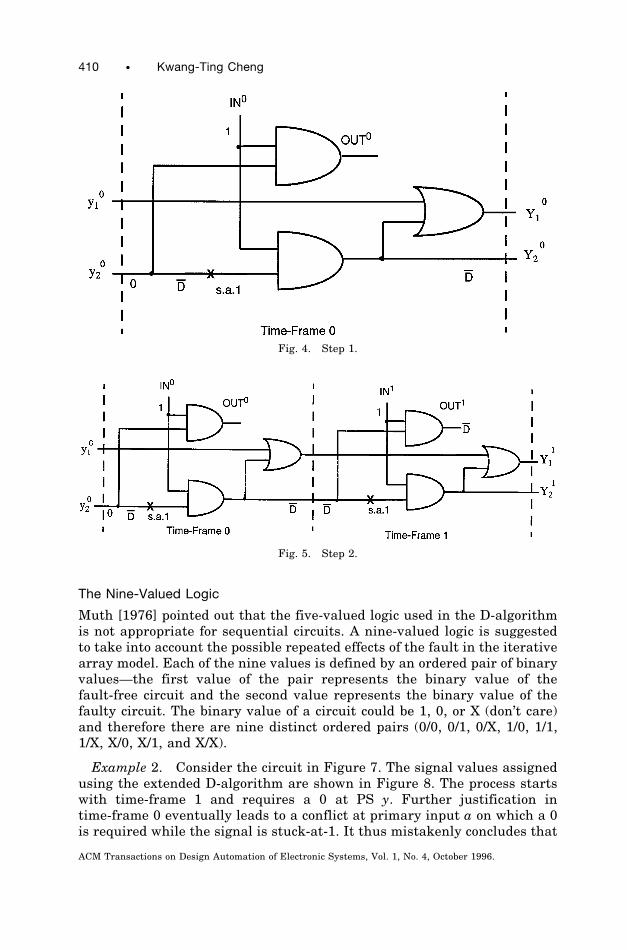
Example 1. Consider the synchronous sequential circuit in Figure 3. Acopy of the combinational portion of the circuit, called time-frame 0, isshown in Figure 4. After the D-algorithm is applied for this time-frame, afault effect D# (i.e., 0/1—the value of the fault-free circuit is 0 and that of thefaulty circuit is 1) appears at the next state line Y2 and a value 0 isrequired at the present state line y2. A new copy of the combination logic,called time-frame 1, is attached to the right of time-frame 0 (fig. 5) forfurther fault propagation. The fault effect can then be successfully propa-gated to the primary output OUT in time-frame 1. The value assigned at y2in time-frame 0 needs justification. Another copy of the combinational logic,called time-frame 21, is attached to the left of time-frame 0 (fig. 6) and thevalue at y2 of time-frame 0 can be successfully justified by assigning a 0 atthe primary input in time-frame 21. Therefore, the test sequence issuccessfully generated. Regardless of the initial states of the sequentialcircuit, sequence {IN 5 0, clock, IN 5 1, clock, IN 5 1} can always producea fault effect at the primary output OUT for the target fault.
Fig. 3. An example.
Gate-Level Test Generation • 409
ACM Transactions on Design Automation of Electronic Systems, Vol. 1, No. 4, October 1996.
The Nine-Valued Logic
Muth [1976] pointed out that the five-valued logic used in the D-algorithmis not appropriate for sequential circuits. A nine-valued logic is suggestedto take into account the possible repeated effects of the fault in the iterativearray model. Each of the nine values is defined by an ordered pair of binaryvalues—the first value of the pair represents the binary value of thefault-free circuit and the second value represents the binary value of thefaulty circuit. The binary value of a circuit could be 1, 0, or X (don’t care)and therefore there are nine distinct ordered pairs (0/0, 0/1, 0/X, 1/0, 1/1,1/X, X/0, X/1, and X/X).
Example 2. Consider the circuit in Figure 7. The signal values assignedusing the extended D-algorithm are shown in Figure 8. The process startswith time-frame 1 and requires a 0 at PS y. Further justification intime-frame 0 eventually leads to a conflict at primary input a on which a 0is required while the signal is stuck-at-1. It thus mistakenly concludes that
Fig. 4. Step 1.
Fig. 5. Step 2.
410 • Kwang-Ting Cheng
ACM Transactions on Design Automation of Electronic Systems, Vol. 1, No. 4, October 1996.
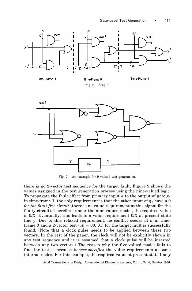
there is no 2-vector test sequence for the target fault. Figure 9 shows thevalues assigned in the test generation process using the nine-valued logic.To propagate the fault effect from primary input a to the output of gate g1in time-frame 1, the only requirement is that the other input of g1 have a 0for the fault-free circuit (there is no value requirement at this signal for thefaulty circuit). Therefore, under the nine-valued model, the required valueis 0/X. Eventually, this leads to a value requirement 0/X at present stateline y. Due to this relaxed requirement, no conflict occurs at a in time-frame 0 and a 2-vector test {ab 5 00, 01} for the target fault is successfullyfound. (Note that a clock pulse needs to be applied between these twovectors. In the rest of the paper, the clock will not be explicitly shown inany test sequence and it is assumed that a clock pulse will be insertedbetween any two vectors.) The reason why the five-valued model fails tofind the test is because it over-specifies the value requirements at someinternal nodes. For this example, the required value at present state line y
Fig. 7. An example for 9-valued test generation.
Fig. 6. Step 3.
Gate-Level Test Generation • 411
ACM Transactions on Design Automation of Electronic Systems, Vol. 1, No. 4, October 1996.
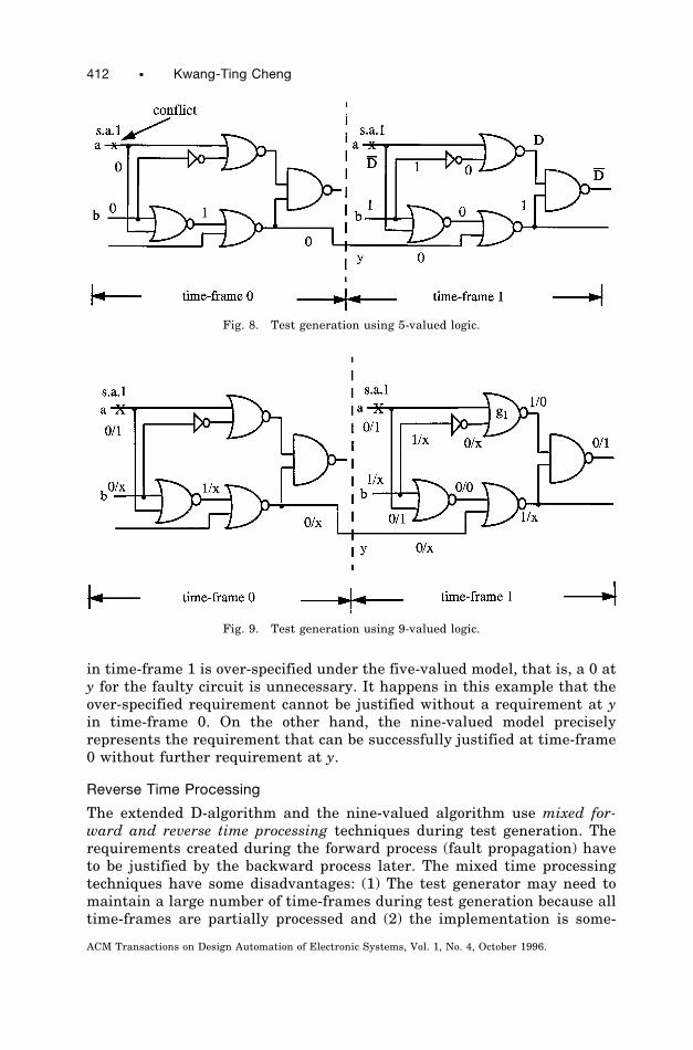
in time-frame 1 is over-specified under the five-valued model, that is, a 0 aty for the faulty circuit is unnecessary. It happens in this example that theover-specified requirement cannot be justified without a requirement at yin time-frame 0. On the other hand, the nine-valued model preciselyrepresents the requirement that can be successfully justified at time-frame0 without further requirement at y.
Reverse Time Processing
The extended D-algorithm and the nine-valued algorithm use mixed for-ward and reverse time processing techniques during test generation. Therequirements created during the forward process (fault propagation) haveto be justified by the backward process later. The mixed time processingtechniques have some disadvantages: (1) The test generator may need tomaintain a large number of time-frames during test generation because alltime-frames are partially processed and (2) the implementation is some-
Fig. 8. Test generation using 5-valued logic.
Fig. 9. Test generation using 9-valued logic.
412 • Kwang-Ting Cheng
ACM Transactions on Design Automation of Electronic Systems, Vol. 1, No. 4, October 1996.
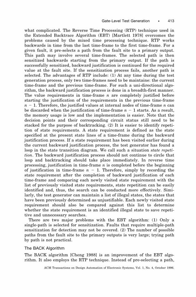
what complicated. The Reverse Time Processing (RTP) technique used inthe Extended Backtrace Algorithm (EBT) [Martlett 1978] overcomes theproblems caused by the mixed time processing technique. RTP worksbackwards in time from the last time-frame to the first time-frame. For agiven fault, it pre-selects a path from the fault site to a primary output.This path may involve several time-frames. The selected path is thensensitized backwards starting from the primary output. If the path issuccessfully sensitized, backward justification is continued for the requiredvalue at the fault site. If the sensitization process fails, another path isselected. The advantages of RTP include: (1) At any time during the testgeneration process, only two time-frames need to be maintaine: the currenttime-frame and the previous time-frame. For such a uni-directional algo-rithm, the backward justification process is done in a breadth-first manner.The value requirements in time-frame n are completely justified beforestarting the justification of the requirements in the previous time-framen 2 1. Therefore, the justified values at internal nodes of time-frame n canbe discarded when the justification of time-frame n 2 1 starts. As a result,the memory usage is low and the implementation is easier. Note that thedecision points and their corresponding circuit status still need to bestacked for the purpose of backtracking. (2) It is easier to identify repeti-tion of state requirements. A state requirement is defined as the statespecified at the present state lines of a time-frame during the backwardjustification process. If a state requirement has been visited earlier duringthe current backward justification process, the test generator has found aloop in the state transition diagram. We call such a situation state repeti-tion. The backward justification process should not continue to circle thatloop and backtracking should take place immediately. In reverse timeprocessing, justification in time-frame n is completed before the beginningof justification in time-frame n 2 1. Therefore, simply by recording thestate requirement after the completion of backward justification of eachtime-frame and comparing each newly visited state requirement with thelist of previously visited state requirements, state repetition can be easilyidentified and, thus, the search can be conducted more effectively. Simi-larly, the test generator can maintain a list of illegal states, the states thathave been previously determined as unjustifiable. Each newly visited staterequirement should also be compared against this list to determinewhether the state requirement is an identified illegal state to save repeti-tive and unnecessary searches.There are two major problems with the EBT algorithm: (1) Only a
single-path is selected for sensitization. Faults that require multiple-pathsensitization for detection may not be covered. (2) The number of possiblepaths from the fault site to the primary outputs is very large; trying pathby path is not practical.
The BACK Algorithm
The BACK algorithm [Cheng 1988] is an improvement of the EBT algo-rithm. It also employs the RTP technique. Instead of pre-selecting a path,
Gate-Level Test Generation • 413
ACM Transactions on Design Automation of Electronic Systems, Vol. 1, No. 4, October 1996.
the BACK algorithm pre-selects a primary output. It assigns a D or D# tothe selected primary output and justifies the value backwards. A testabilitymeasure (called drivability) is used to guide the backward D-justificationfrom the selected primary output to the fault site. Drivability is a measureassociated with a signal that estimates the effort of propagating a D or D#from the fault site to the signal. The drivability measurement is derivedbased on the SCOAP [Goldstein 1979] controllability measurement of bothfault-free and faulty circuits. For a given fault, the drivability measure ofeach signal is computed before test generation starts. In the next twoparagraphs, the definition and the calculation procedure of drivabilitymeasures will be summarized.
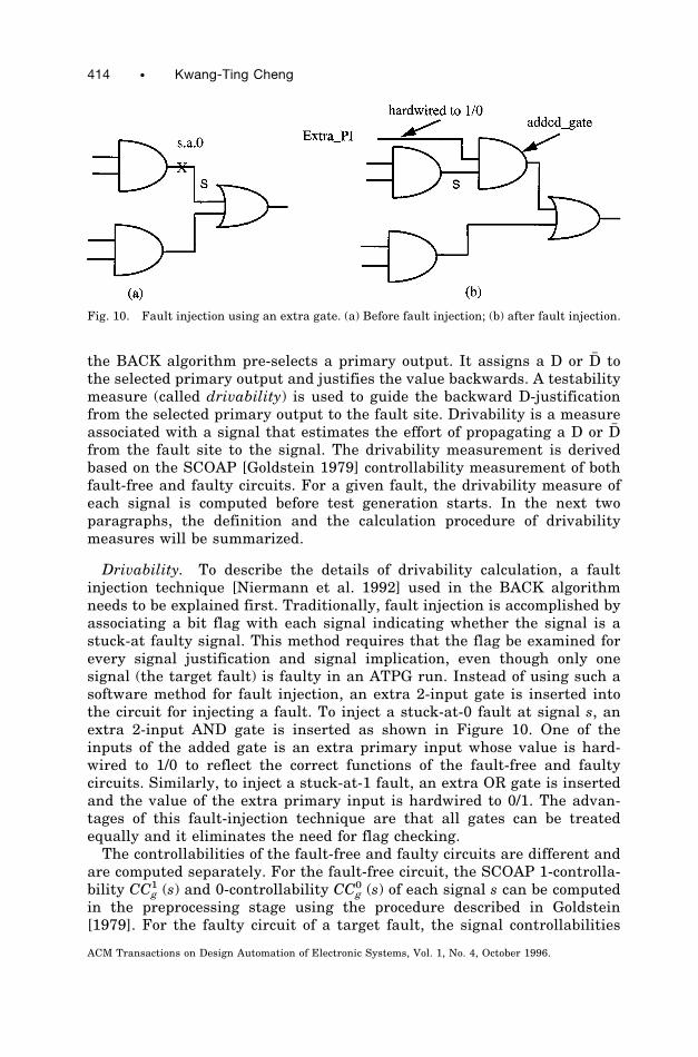
Drivability. To describe the details of drivability calculation, a faultinjection technique [Niermann et al. 1992] used in the BACK algorithmneeds to be explained first. Traditionally, fault injection is accomplished byassociating a bit flag with each signal indicating whether the signal is astuck-at faulty signal. This method requires that the flag be examined forevery signal justification and signal implication, even though only onesignal (the target fault) is faulty in an ATPG run. Instead of using such asoftware method for fault injection, an extra 2-input gate is inserted intothe circuit for injecting a fault. To inject a stuck-at-0 fault at signal s, anextra 2-input AND gate is inserted as shown in Figure 10. One of theinputs of the added gate is an extra primary input whose value is hard-wired to 1/0 to reflect the correct functions of the fault-free and faultycircuits. Similarly, to inject a stuck-at-1 fault, an extra OR gate is insertedand the value of the extra primary input is hardwired to 0/1. The advan-tages of this fault-injection technique are that all gates can be treatedequally and it eliminates the need for flag checking.The controllabilities of the fault-free and faulty circuits are different and
are computed separately. For the fault-free circuit, the SCOAP 1-controlla-bility CCg
1 (s) and 0-controllability CCg0 (s) of each signal s can be computed
in the preprocessing stage using the procedure described in Goldstein[1979]. For the faulty circuit of a target fault, the signal controllabilities
Fig. 10. Fault injection using an extra gate. (a) Before fault injection; (b) after fault injection.
414 • Kwang-Ting Cheng
ACM Transactions on Design Automation of Electronic Systems, Vol. 1, No. 4, October 1996.

CCf1 (s) and CCf
0 (s) for every signal s are computed after the fault isinjected. If an AND gate is injected, the extra primary input is hardwiredto 1/0, and therefore CCg
1 (extra PI) is 0, CCg0 (extra PI) is infinity, CCf
1(s)(extra PI) is infinity, and CCf
0(s) (extra PI) is 0. The controllabilities of thesignals in the fanout cone of the faulty signal can then be updated basedupon the signal controllabilities of the fault-free circuits and the assignedcontrollabilities at the extra primary input. Once the fault-free and faultycontrollabilities of all signals are available, drivabilities can be calculated.Each signal is associated with two drivability measures, D drive andD# drive, indicating the relative effort of propagating a D and a D# from thefault site to the signal. For a signal s not reachable from the fault site, bothD drive(s) and D# drive(s) are infinity. For the extra primary input intro-duced for fault injection, if the hardwired value is 1/0 (0/1), the D drive(D# drive) is set to 0 and the D# (D# drive) is set to infinity. The drivabilitiesof signals at the fanout of the added gate can then be calculated. Forexample, consider a 3-input AND gate G with inputs A, B, and C. Toproduce a D at G requires that one of the inputs has a D and the other twoinputs have value 1 in the fault-free circuit and D drive(G) can be definedas the minimum among {D drive(A) 1 CCg
1 (B) 1 CCg1 (C)}, {D drive(B) 1
CCg1 (A) 1 CCg
1 (C)}, and {D drive(C) 1 CCg1 (A) 1 CCg
1 (B)}. Similarly, topropagate a D# from an input of an AND gate to its output, the other inputsmust have value 1 in the faulty circuit (In this case, the on-input has acontrolling value 0 for the fault-free circuit and thus there is no valuerequirement at other inputs for the fault-free circuit). Therefore,D# drive(G) is defined as the minimum among {D# drive(A) 1 CCf
1 (B) 1
Fig. 11. The BACK algorithm.
Gate-Level Test Generation • 415
ACM Transactions on Design Automation of Electronic Systems, Vol. 1, No. 4, October 1996.
CCf1 (C)}, {D# drive(B) 1 CCf
1 (A) 1 CCf1 (C)}, and {D# drive (C) 1 CCf
1 (A)1 CCf
1 (B)}.To justify a D (D# ) at the output of a gate during backward justification,
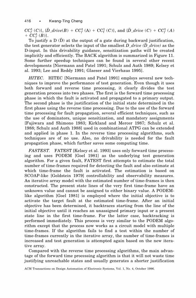
the test generator selects the input of the smallest D drive (D# drive) as theD-input. In this drivability guidance, sensitization paths will be createdimplicitly and efficiently. The BACK algorithm is summarized in Figure 11.Some further speedup techniques can be found in several other recentdevelopments [Niermann and Patel 1991; Schulz and Auth 1989; Kelsey etal. 1993; Lee and Reddy 1991; Glaeser and Vierhaus 1995].
HITEC. HITEC [Niermann and Patel 1991] employs several new tech-niques to improve the performance of test generation. Even though it usesboth forward and reverse time processing, it clearly divides the testgeneration process into two phases. The first is the forward time processingphase in which the fault is activated and propagated to a primary output.The second phase is the justification of the initial state determined in thefirst phase using the reverse time processing. Due to the use of the forwardtime processing for fault propagation, several efficient techniques, such asthe use of dominators, unique sensitization, and mandatory assignments[Fujiwara and Shimono 1983; Kirkland and Mercer 1987; Schulz et al.1988; Schulz and Auth 1988] used in combinational ATPG can be extendedand applied in phase 1. In the reverse time processing algorithms, suchtechniques are of no use. Also, no drivability is needed for the faultpropagation phase, which further saves some computing time.
FASTEST. FATEST [Kelsey et al. 1993] uses only forward time process-ing and uses PODEM [Goel 1981] as the underlying test generationalgorithm. For a given fault, FATEST first attempts to estimate the totalnumber of time-frames required for detecting the fault and also estimate atwhich time-frame the fault is activated. The estimation is based onSCOAP-like [Goldstein 1979] controllability and observability measures.An iterative array model with the estimated number of time-frames is thenconstructed. The present state lines of the very first time-frame have anunknown value and cannot be assigned to either binary value. A PODEM-like algorithm [Goel 1981] is employed where the initial objective is toactivate the target fault at the estimated time-frame. After an initialobjective has been determined, it backtraces starting from the line of theinitial objective until it reaches an unassigned primary input or a presentstate line in the first time-frame. For the latter case, backtracking isperformed immediately. This process is very similar to the PODEM algo-rithm except that the process now works as a circuit model with multipletime-frames. If the algorithm fails to find a test within the number oftime-frames currently in the iterative array, the number of time-frames isincreased and test generation is attempted again based on the new itera-tive array.Compared with the reverse time processing algorithms, the main advan-
tage of the forward time processing algorithm is that it will not waste timejustifying unreachable states and usually generates a shorter justification
416 • Kwang-Ting Cheng
ACM Transactions on Design Automation of Electronic Systems, Vol. 1, No. 4, October 1996.
sequence for bringing the circuit to a hard-to-reach state. For circuits witha large number of unreachable states or hard-to-reach states, the reversetime processing algorithms may spend much time in proving the unreach-able states are unreachable or generating an unduly long sequence to bringthe circuit to a hard-to-reach state. However, the forward time processingalgorithm requires a good estimate of the total number of time-frames andthe time-frame for activating each target fault. If the estimation is notaccurate, the test generator may waste much effort in the smaller-than-necessary iterative array model.
2.1 Some Practical Issues
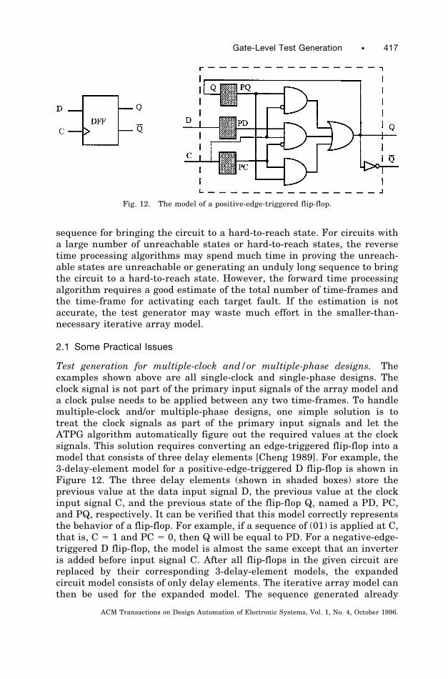
Test generation for multiple-clock and/or multiple-phase designs. Theexamples shown above are all single-clock and single-phase designs. Theclock signal is not part of the primary input signals of the array model anda clock pulse needs to be applied between any two time-frames. To handlemultiple-clock and/or multiple-phase designs, one simple solution is totreat the clock signals as part of the primary input signals and let theATPG algorithm automatically figure out the required values at the clocksignals. This solution requires converting an edge-triggered flip-flop into amodel that consists of three delay elements [Cheng 1989]. For example, the3-delay-element model for a positive-edge-triggered D flip-flop is shown inFigure 12. The three delay elements (shown in shaded boxes) store theprevious value at the data input signal D, the previous value at the clockinput signal C, and the previous state of the flip-flop Q, named a PD, PC,and PQ, respectively. It can be verified that this model correctly representsthe behavior of a flip-flop. For example, if a sequence of (01) is applied at C,that is, C 5 1 and PC 5 0, then Q will be equal to PD. For a negative-edge-triggered D flip-flop, the model is almost the same except that an inverteris added before input signal C. After all flip-flops in the given circuit arereplaced by their corresponding 3-delay-element models, the expandedcircuit model consists of only delay elements. The iterative array model canthen be used for the expanded model. The sequence generated already
Fig. 12. The model of a positive-edge-triggered flip-flop.
Gate-Level Test Generation • 417
ACM Transactions on Design Automation of Electronic Systems, Vol. 1, No. 4, October 1996.
specifies the required values at the clock signals and no additional clocksequence needs to be added between time-frames.
Example 3. Let’s consider a simple circuit that consists of only onepositive-edge-triggered D flip-flop and use the 3-delay-element model tofind a test for the output Q stuck-at-0 fault. The circuit has two inputs Dand C, connected to the data input and the clock input of the flip-flop, andone output Q. There are three possible cubes to set Q to 1 for activating thefault: {C 5 0, PQ 5 1}, {C 5 1, PC 5 0, PD 5 1}, and {PC 5 1, PQ 5 1}. Thefirst and the third cubes require PQ 5 1 and in turn require Q 5 1 again inthe previous time-frame. This is a state repetition and therefore these twocubes need not be further explored. The state requirement of the secondcube, PC 5 0 and PD 5 1, can be easily justified in the previous time-frameby setting C to 0 and D to 1. Therefore, we can conclude that the test isvector (CD 5 01) followed by vector (CD 5 1X), which is indeed the correcttest.
Test generation for circuits with combinational loops. For circuits withsome combinational feedback loops (i.e., loops that do not contain anyflip-flops), the iterative array model can still be applied. This extension hasbeen discussed in Chappell [1974] and Breuer [1974]. A set of feedbackconnections whose removal will eliminate all combinational feedback loopsis first identified. At each of these combinational feedback lines, a pseudodelay element is inserted to create a new circuit model for test generation.The iterative array model is then constructed for the modified circuit whichconsists of two types of delay elements: regular delay elements (that areeither D flip-flops in a single-clock/single-phase design or the ones in the3-delay-element model discussed in the last paragraph) and the pseudodelay elements. In the iterative array model, the inputs to a time-frameinclude the primary inputs, the present state lines, and the outputs of thepseudo delay elements (called pseudo present state lines PPS). Similarly,the outputs of a time-frame consist of the primary outputs, the next statelines, and the inputs of the pseudo delay elements (called pseudo next statelines PNS). During test generation, additional constraints are imposed. Forthe time-frames in which at least one PPS/PNS line pair (associated with apseudo delay element) does not have consistent binary values, each PS/NSline pair (associated with a delay element) is forced to have the samebinary value and the primary inputs are not allowed to change values. If aPPS/PNS line pair does not have consistent binary values, the actual valueat the corresponding combinational feedback line has not stabilized yet, sothe clock should not be applied and the primary input vector should notchange. By imposing such constraints, the iterative array will contain somefine-grained time-frames for consistent justification for the combinationalfeedback lines and some coarse-grained time-frames for value justificationand fault propagation across the flip-flops.
Efficient identification of undetectable faults. Sequential ATPG is acomplex search process. In principle, test generators are tuned to perform a
418 • Kwang-Ting Cheng
ACM Transactions on Design Automation of Electronic Systems, Vol. 1, No. 4, October 1996.
depth-first search such that a test sequence can be found as short and earlyas possible. A test generator will report a fault as undetectable afterimplicitly exhausting the search space. Because the search strategy isoptimized for finding a test (instead of determining whether a fault isdetectable or not), the undetectable faults are hard to identify and the testgenerators usually spend a significant fraction of total computation time onthese undetectable faults. To limit the computational resource allocated toeach fault, a test generator usually sets a limit on the time budget and alimit on the maximum number of time-frames for each target fault. Forundetectable faults in larger circuits, the CPU time limit is usually reachedbefore the search space is exhausted and they are usually classified asaborted faults instead of undetectable faults. Therefore, it may be worth-while to add a preprocessing phase before ATPG which is dedicated toidentifying undetectable faults and employs a different search strategy.Several approaches suggest ways to identify a subset of undetectable
faults based on efficient procedures [Cheng 1993; Agrawal and Chakradhar1995; Pomeranz and Reddy 1994; Iyer and Abramovici 1994]. For example,a fault which is undetectable under the assumption that all state lines arefully controllable and observable (i.e., combinationally undetectable) is alsoa sequentially undetectable fault. Such an undetectable fault can be muchmore efficiently identified by a combinational circuit test generator. Notethat such a fault may not be identified as an undetectable fault by asequential circuit test generator if just one time-frame is allowed. Forexample, if the BACK algorithm is used for a combinationally undetectablefault and a fault effect (D or D# ) is assigned to a primary output, it is stillpossible that the fault effect may be back propagated to a present state lineof this time-frame and the fault cannot be identified as undetectable usingjust one-time-frame sequential ATPG. A procedure for identifying a specialclass of undetectable faults, called feedback-free sequentially undetectablefaults, is suggested in Cheng 1993. The procedure first converts a sequen-tial circuit into a feedback-free model by assuming a set of feedback lines asfully controllable and observable. A fault which is undetectable under thismodel will also be sequentially undetectable. The method proposed inAgrawal and Chakradhar [1995] uses a combinational circuit test generatorto target faults in the iterative array model with a pre-specified, smallnumber of time-frames. It assumes that the next-state lines of the last (i.e.,rightmost) time-frames are fully observable and the present state lines ofthe first (i.e., leftmost) time-frames are fully controllable. Two differentprocedures are suggested to identify a subset of sequentially undetectablefaults: one assumes that only the last time-frame of the array model hasthe target fault and the other time-frames are all fault-free; the otherassumes that every time-frame in the array model has the target fault. Inother words, the first procedure targets a single-stuck-at fault in the arraymodel and the second procedure targets a multiple-stuck-at fault. It hasbeen shown [Agrawal and Chakradhar 1995; Pomeranz and Reddy 1994]that a combinationally undetectable fault in the iterative array modelidentified by either one of the two procedures corresponds to a sequentially
Gate-Level Test Generation • 419
ACM Transactions on Design Automation of Electronic Systems, Vol. 1, No. 4, October 1996.
undetectable fault in the original circuit. Therefore, such techniques willallow identification of a subset of sequentially undetectable faults usingmore efficient combinational techniques. In Pomeranz and Reddy [1994], amore detailed characterization of these undetectable faults in terms of theirclassification with respect to redundancy is given. The relationship be-tween undetectability and redundancy will be discussed in more details inSection 2.2. In Iyer and Abramovici [1994], an efficient algorithm basedpurely on implication is proposed. The algorithm relies on identifyingillegal value combinations (also called conflicts) on a subset of signals inthe circuit. Faults for which these illegal value combinations are necessaryfor detection are then found as sequentially undetectable.
Test efficiency. The fault coverage figures achieved by the test sequenceproduced by a test generator may not be a fair indicator of the testgenerator’s performance. Determining the set of undetectable faults is alsoan objective of test generation. Therefore, the test efficiency, defined as theratio of the number of detected faults plus the number of identifiedundetectable faults to the total number of faults, is usually used toevaluate the efficiency of a test generator.
Robust Tests for Asynchronous Preset/Clear Lines and for Busses
Special attention needs to be paid for asynchronous preset/clear lines. Nohazards or glitches are allowed at these signals; otherwise the test may beinvalidated. This problem has been discussed in detail in Breuer andHarrison [1974].
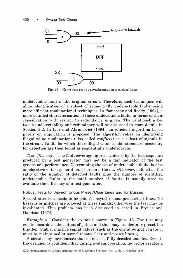
Example 4. Consider the example shown in Figure 13. The test maycreate hazards at the output of gate a and thus may accidentally preset theflip-flop. Stable, inactive signal values, such as the one at output of gate b,must be maintained at asynchronous clear and preset lines. qA circuit may have busses that do not use fully decoded enables. Even if
the designer is confident that during system operation, no vector creates a
Fig. 13. Nonrobust test at asynchronous preset/clear lines.
420 • Kwang-Ting Cheng
ACM Transactions on Design Automation of Electronic Systems, Vol. 1, No. 4, October 1996.
state that could cause bus contention or bus floating, it cannot be guaran-teed that the sequences generated by an ATPG tool would not cause busproblems. The ATPG tools need to make sure that the sequence generatedwill not cause bus contention or leave the bus floating, even for thosebusses not in the fanin or fanout cones of the target fault. This constraintcan be implemented by adding some fictitious logic to the fanin of the busenables and data signals to make sure that one or more bus enables areactive. If more than one enables are active, the fictitious logic will force thecorresponding bus data to be consistent.
Complexity of Sequential ATPG
For the topological analysis based approaches, the complexity can beroughly measured by the average number of vectors (therefore, time-frames) required for detecting a fault in the given network. In general, theaverage number of vectors for detecting a fault is highly related to thestructure of the sequential circuit and attributes, such as sequential depth(the maximum number of flip-flops encountered in any path from a primaryinput to a primary output), number of sequential cycles (a sequential cycleexists if a flip-flop’s data input is in the fanout cone of the flip-flop’soutput), and the maximum length of any sequential cycles (the length of acycle is defined as the number of flip-flops in the feedback loop). Thepresence of sequential cycles increases the temporal correlations of valueson specific nodes and costs more time-frames to justify specific values atinternal nodes. It has been shown [Miczo 1986; Cheng and Agrawal 1989;Gupta and Breuer 1990] that the computational complexity of test genera-tion for a cycle-free sequential circuit is not too much higher than that for acombinational circuit. For a cycle-free circuit with a sequential depth D,any detectable single-stuck-at fault can be detected by a sequence of lengthD 1 1. Therefore, for such circuits, there is a small upper-bound on thenumber of time-frames for each test generation attempt and a high faultcoverage can usually be achieved. Empirical studies have also shown thatthe average number of time-frames is somewhat linearly proportional tothe sequential depth of a circuit and is exponential in terms of themaximum cycle length [Miczo 1986; Cheng and Agrawal 1989].ATPG may waste a substantial amount of runtime in fruitless justifica-
tion of invalid states (defined as the states that cannot be reached from thereset state). The computational complexity caused by such fruitless effortsis not reflected in the above mentioned circuit attributes such as sequentialdepth and sequential cycles. Recently, it has been pointed out [Marchok etal. 1995] that density of encoding, defined as the ratio of the number ofvalid states to the total number of states, is a key indicator of topological-analysis-based sequential ATPG. The lower the ratio, the more the invalidstate, and the higher the probability of a sequential ATPG wasting time injustifying them during test generation. It has been shown [Marchok et al.1995] that ATPG spent significantly longer CPU time and achieved a lowerfault coverage for a retimed version of a sequential circuit that has a muchlower density of encoding than the original circuit.
Gate-Level Test Generation • 421
ACM Transactions on Design Automation of Electronic Systems, Vol. 1, No. 4, October 1996.
2.2 Undetectability and Redundancy
For combinational circuits or full-scan sequential circuits, a fault is calledundetectable if no input sequence can produce a fault effect (D or D# ) at anyprimary output, and a fault is called redundant if the presence of the faultdoes not change the input/output behavior of the circuit. The detectabilityis associated with a test generation procedure while redundancy is associ-ated with functional specification of a design. A fault is combinationallyredundant if it is reported as undetectable by a complete combinational testgenerator. The definitions of detectability and redundancy for (non-scan)sequential circuits are much more complicated [Abramovici et al. 1990;Cheng 1993; Pomeranz and Reddy 1993], and these two properties (redun-dancy and undetectability of stuck-at faults) are no longer equivalent[Abramovici et al. 1990; Cheng 1993; Pomeranz and Reddy 1993]. It ispointed out in Pomeranz and Reddy [1993] that undetectability can beprecisely defined only if a test strategy is specified, and redundancy cannotbe defined unless the operational mode of the circuit is known. Formal andprecise definitions of undetectability with respect to four different teststrategies, namely full-scan, reset, multiple observation time, and singleobservation time, are given, and redundancies with respect to three differ-ent circuit operational modes, namely reset, synchronization, and non-synchronization are also defined in Pomeranz and Reddy [1993]. A fault iscalled undetectable under full-scan if it is combinationally undetectable[DeVadas 1990]. In the case where hardware reset is available, a fault issaid to be undetectable under the reset strategy if no input sequence existssuch that the output response of the fault-free circuit is different from theresponse of the faulty circuit, both starting from their reset states. In thecase where hardware reset is not available, there are two different teststrategies: the multiple observation time (MOT) strategy and the singleobservation time (SOT) strategy. Under the SOT strategy, a sequencedetects a fault only if a fault effect appears at the same primary output Oiand at the same vector Vj for all power-up initial state-pairs of thefault-free and faulty circuits (Oi could be any primary output and Vj couldbe any vector in the sequence). Most gate-level test generators and allATPG algorithms mentioned in Section 2 assume the SOT test strategy.Under the MOT strategy, a fault can be detected by multiple inputsequences—each input sequence produces a fault effect at some primaryoutput for a subset of power-up initial state-pairs and the union of thesubsets covers all possible power-up initial state-pairs (for a n-flip-flopcircuit, there are 22n power-up initial state-pairs). Under the MOT strat-egy, it is also possible to detect a fault using a single test sequence for whichfault effects appear at different primary outputs and/or different vectors fordifferent power-up initial state-pairs.
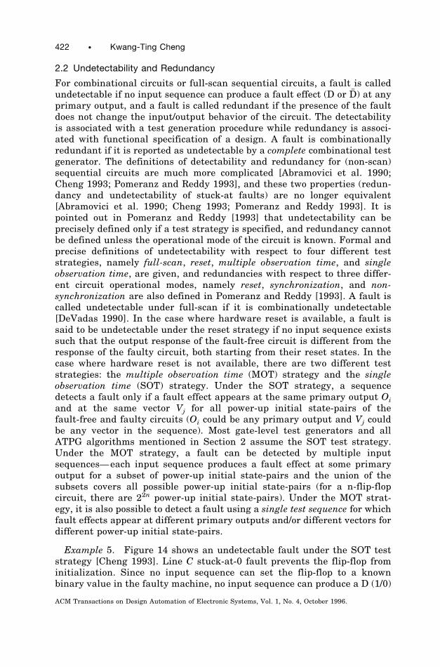
Example 5. Figure 14 shows an undetectable fault under the SOT teststrategy [Cheng 1993]. Line C stuck-at-0 fault prevents the flip-flop frominitialization. Since no input sequence can set the flip-flop to a knownbinary value in the faulty machine, no input sequence can produce a D (1/0)
422 • Kwang-Ting Cheng
ACM Transactions on Design Automation of Electronic Systems, Vol. 1, No. 4, October 1996.
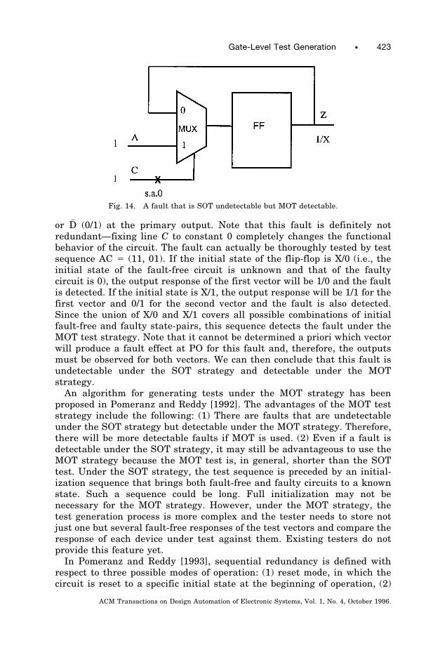
or D# (0/1) at the primary output. Note that this fault is definitely notredundant—fixing line C to constant 0 completely changes the functionalbehavior of the circuit. The fault can actually be thoroughly tested by testsequence AC 5 (11, 01). If the initial state of the flip-flop is X/0 (i.e., theinitial state of the fault-free circuit is unknown and that of the faultycircuit is 0), the output response of the first vector will be 1/0 and the faultis detected. If the initial state is X/1, the output response will be 1/1 for thefirst vector and 0/1 for the second vector and the fault is also detected.Since the union of X/0 and X/1 covers all possible combinations of initialfault-free and faulty state-pairs, this sequence detects the fault under theMOT test strategy. Note that it cannot be determined a priori which vectorwill produce a fault effect at PO for this fault and, therefore, the outputsmust be observed for both vectors. We can then conclude that this fault isundetectable under the SOT strategy and detectable under the MOTstrategy.An algorithm for generating tests under the MOT strategy has been
proposed in Pomeranz and Reddy [1992]. The advantages of the MOT teststrategy include the following: (1) There are faults that are undetectableunder the SOT strategy but detectable under the MOT strategy. Therefore,there will be more detectable faults if MOT is used. (2) Even if a fault isdetectable under the SOT strategy, it may still be advantageous to use theMOT strategy because the MOT test is, in general, shorter than the SOTtest. Under the SOT strategy, the test sequence is preceded by an initial-ization sequence that brings both fault-free and faulty circuits to a knownstate. Such a sequence could be long. Full initialization may not benecessary for the MOT strategy. However, under the MOT strategy, thetest generation process is more complex and the tester needs to store notjust one but several fault-free responses of the test vectors and compare theresponse of each device under test against them. Existing testers do notprovide this feature yet.In Pomeranz and Reddy [1993], sequential redundancy is defined with
respect to three possible modes of operation: (1) reset mode, in which thecircuit is reset to a specific initial state at the beginning of operation, (2)
Fig. 14. A fault that is SOT undetectable but MOT detectable.
Gate-Level Test Generation • 423
ACM Transactions on Design Automation of Electronic Systems, Vol. 1, No. 4, October 1996.
synchronization mode, in which the operation starts with a specific initial-ization sequence, and (3) no-synchronization mode, in which the operationstarts from the state in which the circuit happens to be. A fault isredundant under a given mode of operation if, for all possible inputsequences applicable under the given mode of operation, the fault does notchange the expected output responses. For circuits with a hardware reset, afault is undetectable under the reset test strategy if and only if the fault isredundant under the reset mode of operation. The notion of partial testsintroduced in Pomeranz and Reddy [1993] is useful in understanding therelationship between undetectability and redundancy under the synchroni-zation and the no-synchronization modes of operation. A partial test is aninput sequence such that for at least one initial state of the faulty circuit,the output response of the faulty circuit is different from the response ofthe fault-free circuit [Pomeranz and Reddy 1993]. A fault is called partiallydetectable if at least one partial test exists. It is shown [Cheng 1993;Pomeranz and Reddy 1993] that a fault is redundant if and only if it is notpartially detectable. A modification to the sequential circuit test generationalgorithm for identifying partially detectable faults can be found in Cheng1993.
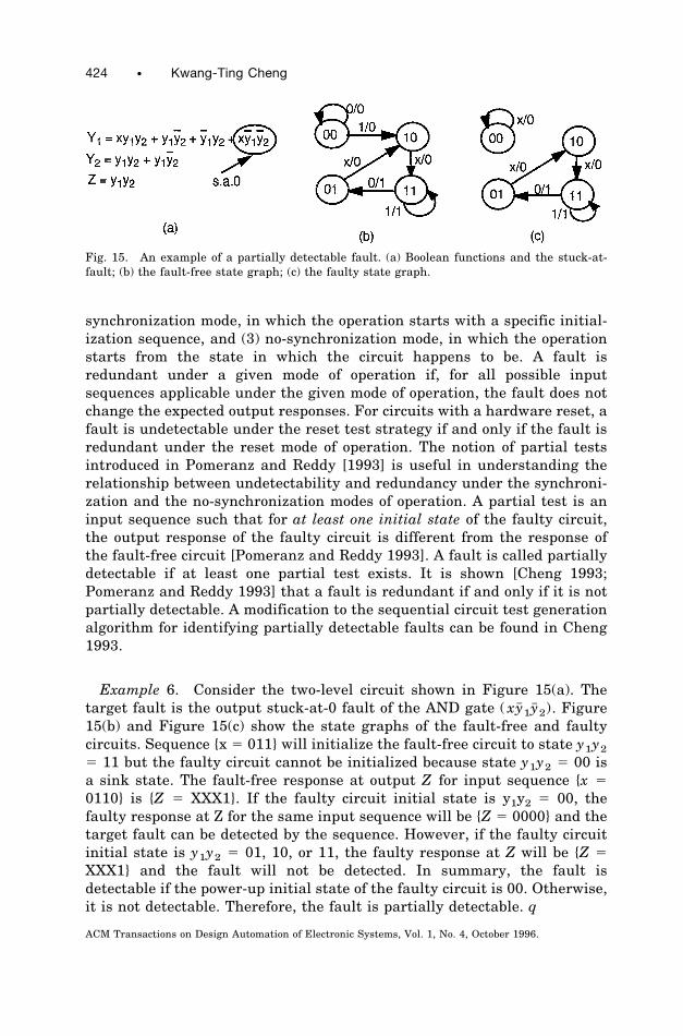
Example 6. Consider the two-level circuit shown in Figure 15(a). Thetarget fault is the output stuck-at-0 fault of the AND gate ( xy# 1y# 2). Figure15(b) and Figure 15(c) show the state graphs of the fault-free and faultycircuits. Sequence {x 5 011} will initialize the fault-free circuit to state y1y25 11 but the faulty circuit cannot be initialized because state y1y2 5 00 isa sink state. The fault-free response at output Z for input sequence {x 50110} is {Z 5 XXX1}. If the faulty circuit initial state is y1y2 5 00, thefaulty response at Z for the same input sequence will be {Z 5 0000} and thetarget fault can be detected by the sequence. However, if the faulty circuitinitial state is y1y2 5 01, 10, or 11, the faulty response at Z will be {Z 5XXX1} and the fault will not be detected. In summary, the fault isdetectable if the power-up initial state of the faulty circuit is 00. Otherwise,it is not detectable. Therefore, the fault is partially detectable. q
Fig. 15. An example of a partially detectable fault. (a) Boolean functions and the stuck-at-fault; (b) the fault-free state graph; (c) the faulty state graph.
424 • Kwang-Ting Cheng
ACM Transactions on Design Automation of Electronic Systems, Vol. 1, No. 4, October 1996.
2.3 Deficiencies
Theoretical limitation. Consider a 20-bit counter. It takes a sequence of219 vectors to detect the stuck-at-0 fault at the most significant bit.Therefore, this many time-frames would be required in the test generationprocess. Such a small but highly sequential circuit could hardly be handledby any gate-level ATPG tool. Sequential ATPG is by no means a completesolution for highly sequential circuits. However, sequential ATPG com-bined with design-for-testability techniques such as partial scan offers acomplete solution. The relationship between sequential ATPG and partialscan will be discussed in Section 5.
Timing. Timing is not properly considered by approaches based on theiterative array model for circuits with combinational loops and for multiple-phase or multiple-clock designs, as discussed earlier. Even though we canconstruct an iterative array model for an asynchronous circuit and applythe path sensitization technique on the model to generate tests, the testsgenerated in such a manner may cause races and hazards.
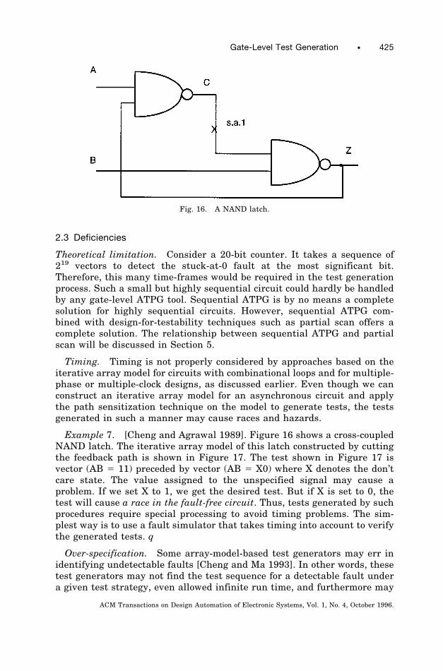
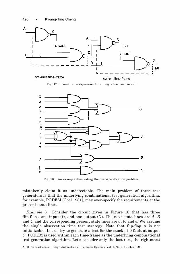
Example 7. [Cheng and Agrawal 1989]. Figure 16 shows a cross-coupledNAND latch. The iterative array model of this latch constructed by cuttingthe feedback path is shown in Figure 17. The test shown in Figure 17 isvector (AB 5 11) preceded by vector (AB 5 X0) where X denotes the don’tcare state. The value assigned to the unspecified signal may cause aproblem. If we set X to 1, we get the desired test. But if X is set to 0, thetest will cause a race in the fault-free circuit. Thus, tests generated by suchprocedures require special processing to avoid timing problems. The sim-plest way is to use a fault simulator that takes timing into account to verifythe generated tests. q
Over-specification. Some array-model-based test generators may err inidentifying undetectable faults [Cheng and Ma 1993]. In other words, thesetest generators may not find the test sequence for a detectable fault undera given test strategy, even allowed infinite run time, and furthermore may
Fig. 16. A NAND latch.
Gate-Level Test Generation • 425
ACM Transactions on Design Automation of Electronic Systems, Vol. 1, No. 4, October 1996.
mistakenly claim it as undetectable. The main problem of these testgenerators is that the underlying combinational test generation algorithm,for example, PODEM [Goel 1981], may over-specify the requirements at thepresent state lines.
Example 8. Consider the circuit given in Figure 18 that has threeflip-flops, one input (I), and one output (O). The next state lines are A, Band C and the corresponding present state lines are a, b, and c. We assumethe single observation time test strategy. Note that flip-flop A is notinitializable. Let us try to generate a test for the stuck-at-0 fault at outputO. PODEM is used within each time-frame as the underlying combinationaltest generation algorithm. Let’s consider only the last (i.e., the rightmost)
Fig. 18. An example illustrating the over-specification problem.
Fig. 17. Time-frame expansion for an asynchronous circuit.
426 • Kwang-Ting Cheng
ACM Transactions on Design Automation of Electronic Systems, Vol. 1, No. 4, October 1996.
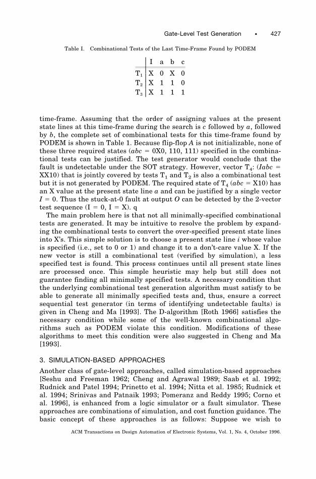
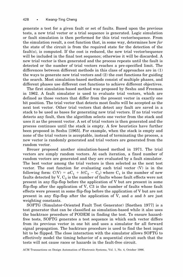
time-frame. Assuming that the order of assigning values at the presentstate lines at this time-frame during the search is c followed by a, followedby b, the complete set of combinational tests for this time-frame found byPODEM is shown in Table 1. Because flip-flop A is not initializable, none ofthese three required states (abc 5 0X0, 110, 111) specified in the combina-tional tests can be justified. The test generator would conclude that thefault is undetectable under the SOT strategy. However, vector T4: (Iabc 5XX10) that is jointly covered by tests T1 and T2 is also a combinational testbut it is not generated by PODEM. The required state of T4 (abc 5 X10) hasan X value at the present state line a and can be justified by a single vectorI 5 0. Thus the stuck-at-0 fault at output O can be detected by the 2-vectortest sequence (I 5 0, I 5 X). qThe main problem here is that not all minimally-specified combinational
tests are generated. It may be intuitive to resolve the problem by expand-ing the combinational tests to convert the over-specified present state linesinto X’s. This simple solution is to choose a present state line i whose valueis specified (i.e., set to 0 or 1) and change it to a don’t-care value X. If thenew vector is still a combinational test (verified by simulation), a lessspecified test is found. This process continues until all present state linesare processed once. This simple heuristic may help but still does notguarantee finding all minimally specified tests. A necessary condition thatthe underlying combinational test generation algorithm must satisfy to beable to generate all minimally specified tests and, thus, ensure a correctsequential test generator (in terms of identifying undetectable faults) isgiven in Cheng and Ma [1993]. The D-algorithm [Roth 1966] satisfies thenecessary condition while some of the well-known combinational algo-rithms such as PODEM violate this condition. Modifications of thesealgorithms to meet this condition were also suggested in Cheng and Ma[1993].
3. SIMULATION-BASED APPROACHES
Another class of gate-level approaches, called simulation-based approaches[Seshu and Freeman 1962; Cheng and Agrawal 1989; Saab et al. 1992;Rudnick and Patel 1994; Prinetto et al. 1994; Nitta et al. 1985; Rudnick etal. 1994; Srinivas and Patnaik 1993; Pomeranz and Reddy 1995; Corno etal. 1996], is enhanced from a logic simulator or a fault simulator. Theseapproaches are combinations of simulation, and cost function guidance. Thebasic concept of these approaches is as follows: Suppose we wish to
Table I. Combinational Tests of the Last Time-Frame Found by PODEM
I a b c
T1 X 0 X 0T2 X 1 1 0T3 X 1 1 1
Gate-Level Test Generation • 427
ACM Transactions on Design Automation of Electronic Systems, Vol. 1, No. 4, October 1996.
generate a test for a given fault or set of faults. Based upon the previoustests, a new trial vector or a trial sequence is generated. Logic simulationor fault simulation is then performed for this trial vector/sequence. Fromthe simulation result, a cost function that, in some way, determines how farthe state of the circuit is from the required state for the detection of thefault(s), is computed. If the cost is reduced, the new trial vector/sequencewill be included in the final test sequence; otherwise it will be discarded. Anew trial vector is then generated and the process repeats until the fault isdetected or the number of trial vectors reaches a pre-specified limit. Thedifferences between different methods in this class of approaches are in (1)the ways to generate new trial vectors and (2) the cost functions for guidingthe search. Most simulation-based methods consist of multiple phases, anddifferent phases use different cost functions to achieve different objectives.The first simulation-based method was proposed by Seshu and Freeman
in 1962. A fault simulator is used to evaluate trial vectors, which aredefined as those vectors that differ from the present vector in exactly onebit position. The trial vector that detects most faults will be accepted as thenext test vector. Other trial vectors that detect any fault are saved in astack to be used as bases for generating new trial vectors. If no trial vectordetects any fault, then the algorithm selects one vector from the stack anduses it as the present vector. A set of trial vectors is then generated and theprocess continues until the stack is empty. A few heuristics have furtherbeen proposed in Seshu [1965]. For example, when the stack is empty andnone of the trial vectors is acceptable, instead of terminating the process, anew vector is randomly generated and trial vectors are generated from therandom vector.Breuer proposed another simulation-based method in 1971. The trial
vectors are simply random vectors. At each iteration, a fixed number ofrandom vectors are generated and they are evaluated by a fault simulator.The best vector among the trial vectors is then selected as the next testvector. The cost function for evaluating each trial vector (V) is in thefollowing form: C(V) 5 aC1 1 b(C2 2 C3) where C1 is the number of newfaults detected by V, C2 is the number of faults whose fault effects were notpresent in any flip-flop before the application of V but are present in someflip-flop after the application of V, C3 is the number of faults whose faulteffects were present in some flip-flop before the application of V but are notpresent in any flip-flop after the application of V, and a and b are justweighting constants.SOFTG (Simulator-Oriented Fault Test Generator) [Snethen 1977] is a
test generator that can be classified as simulation-based while it also usesthe backtrace procedure of PODEM in finding the test. To ensure hazard-free tests, SOFTG generates a test sequence in which each vector differsfrom its previous vector in one bit and uses a simulator for all forwardsignal propagation. The backtrace procedure is used to find the best inputbit to be flipped. The close interaction with the simulator allows SOFTG toeffectively model the timing behavior of a sequential circuit such that thetests will not cause races or hazards in the fault-free circuit.
428 • Kwang-Ting Cheng
ACM Transactions on Design Automation of Electronic Systems, Vol. 1, No. 4, October 1996.
CONTEST [Cheng and Agrawal 1989] is a test generator enhanced froma concurrent fault simulator. CONTEST generates a new trial vector bychanging a single bit in the last accepted vector. The test generationprocess is subdivided into three phases with a different cost function foreach phase: (1) Initialization phase—to bring flip-flops in the circuit intoknown states irrespective of the starting state. The cost function of thisphase is simply the number of uninitialized flip-flops. Initially, the costmay be equal to the number of flip-flops in the circuit. The goal is to reducethis cost to 0. (2) Concurrent fault detection phase—the objective is togenerate tests effectively by targeting all undetected faults concurrently.The cost function of a fault is defined as the minimum distance of any faulteffects created by this fault to any primary output. The distance is simplythe number of logic gates on the path. The smaller the cost, the closer thefault is to being detected. When a fault is detected, its cost will be zero. If afault is not activated, the cost is defined as infinity. In general, there aremany undetected faults in phase 2. The costs of all undetected faults for thecurrent vector and for the candidate trial vector needs to be computed. Todetermine whether to accept the candidate vector or reject it, two lists ofcost functions instead of two numbers are compared. That is, the search fortests is guided by a group of faults instead of a single target fault. Based onthis principle, a simple cost function for a trial vector can be defined as thesum of, say, 10% of the lowest cost undetected faults. The concurrent phasestops when no single bit changes in the current vector produce costreduction. This will normally happen when a small number of faults is leftin the target set. (3) Single fault detection phase—test vectors are gener-ated for a single target fault. The cost function is based on a SCOAP-liketestability measure [Goldstein 1979]. For a target fault, dynamic testabilitymeasures that estimate the minimum number of primary inputs of thecurrent vector that must be changed and the minimum number of addi-tional vectors that must be applied for detecting the fault are used tomeasure the cost of a trial vector and to guide vector generation. Similar tophase 2, a new trial vector is generated based on a single bit change of thecurrent vector.
3.1 Generating Trial Vectors by Genetic Algorithm
CRIS [Saab et al. 1992], another simulation-based test generator, uses twocost functions that are based on (1) the distance of the fault effects to theprimary outputs and (2) the distribution of the switching activity of thepreviously generated tests. The first cost function is similar to the one usedin phase 2 of CONTEST. The second cost function is used to select vectorsthat would create more switching activity for the portion of the circuit thathas a low level of switching activity for the previously generated tests.Increasing the switching activity in an inactive subcircuit would increasethe probability of detecting faults in that subcircuit. CRIS uses the geneticalgorithms [Goldberg 1989] to generate new trial vectors. The new trialvectors are generated by some basic evolutionary operators of genetic
Gate-Level Test Generation • 429
ACM Transactions on Design Automation of Electronic Systems, Vol. 1, No. 4, October 1996.
algorithms such as reproduction (copying potentially useful candidatevectors and sequences), mutation (flipping bits in a vector), splicing ofvectors (producing a new vector using substrings from two other vectors), orsequences (producing a new sequence from subsequences of existing se-quences). The information collected during simulation (such as activity ofinternal nodes and nodes where the fault effects were blocked) is used toidentify bits for mutation or the vectors and sequences for splicing. GATTO[Prinetto et al. 1994] is another simulation-based method using geneticalgorithms. Similar to CRIS, the cost function of GATTO is to maximize thecircuit activity.GATEST [Rudnick et al. 1994] uses genetic algorithms to generate new
trial vectors as well as new trial sequences. The cost function (called fitnessfunction in genetic algorithms) of each trial vector or sequence is evaluatedby a fault simulator. The main objective of the fitness function is tomaximize the number of faults detected and the number of fault effectspropagated to flip-flops. GATEST consists of four phases: (1) Phase 1 (theinitialization phase)—The fitness function consists of two terms. The firstis the count of initialized flip-flops, which is the same as the phase 1 costfunction used by CONTEST. The second term is the fraction of flip-flopschanging values after the application of the vector under evaluation. Thesecond term is used to differentiate vectors that cause the same number offlip-flops to be initialized. The vector that causes more state variables tochange values is preferred. When all flip-flops are initialized, the programenters phase 2. (2) Phase 2—The fitness function is the sum of two terms:(i) the number of faults it detects and (ii) the number of faults whose faulteffects propagated to flip-flops are divided by the product of the totalnumber of faults and the total number of flip-flops. Again, the second termis a fraction and is used to differentiate vectors that detect the samenumber of faults. Once a test vector is generated that detects no additionalfaults, the program enters the next phase. (3) Phase 3—The fitnessfunction consists of three terms and the first two terms are identical tothose of phase 2. The third term is the total number of good and faultycircuit events divided by the product of the total number of nodes and thetotal number of faults. This cost function is used to select the vectors thatcreate high good and faulty circuit activity levels. In phase 3, the vectorsnormally do not detect any fault (i.e., the first term is zero) and theobjective is to change the circuit to a new state such that additional faultscan be detected. When a fault is detected in phase 3, the program goes backto phase 2 and the process repeats. If the number of vectors generated inphase 3 exceeds a limit, the program enters the final phase. (4) Phase4—The fitness function is evaluated for trial sequences instead of individ-ual trial vectors. The fitness function of a trial sequence is very similar tothat of phase 2 for a trial vector, except that the second term is furtherdivided by the trial sequence length.It has been pointed out in Rudnick et al. [1994] that several genetic
algorithm parameters are important in achieving good results. The GAparameters include the population size (i.e., the number of vectors used to
430 • Kwang-Ting Cheng
ACM Transactions on Design Automation of Electronic Systems, Vol. 1, No. 4, October 1996.
generate new trial vectors), the number of generations for evolving thevectors, and the crossover and mutation probabilities in evolving thevectors.The simulation-based approaches have several advantages: (1) Logic
simulation and fault simulation deal with circuit delays in a very naturalway, and therefore even highly asynchronous sequential circuits can behandled. It can be assured that the sequence generated by such approacheswill not cause hazards/races in the asynchronous circuits. (2) Because afault simulator can accept a transistor-level netlist, it can handle transis-tor-level fault models. (3) Fault simulators, in general, require less CPUrun time than array-model-based approaches.The major disadvantages of the simulation-based approaches are: (1)
Unlike the array-model-based approaches, these methods cannot identifyundetectable faults. (2) They may also fail to generate tests for certainhard-to-activate faults. The guidance provided by the cost functions of thesefaults is usually very weak. (3) The test sequence generated tends to belonger than that generated by the array-model-based approach.
3.2 Hybrid Approaches
A number of hybrid methods have recently been proposed that combine thesimulation-based technique with topological-analysis-based techniques[Saab et al. 1994; Rudnick and Patel 1995; Hsiao et al. 1996]. CRIS-hybrid[Saab et al. 1994] combines CRIS [Rudnick et al. 1994] with a iterative-array-model-based ATPG in a loose way. When CRIS generates a fixednumber of test vectors without improving the fault coverage, array-model-based test generation is applied to get a set of vectors to be added to boththe final test sequence and also to the current population to be used fortrial vector generation for further call to CRIS. The array-model-based testgeneration is also used to identify untestable faults. The results show thatthis hybrid method results in test sequences of a better quality in terms ofboth test length and fault coverage as compared to CRIS. GA-HITEC[Rudnick and Patel 1995], another hybrid test generator, uses topologicalalgorithms for fault excitation and fault propagation and uses geneticalgorithms for state justification. If the genetic approach is not successful,topological-analysis-based procedures are further used for state justifica-tion. Further improvement to GA-HITEC, to closely integrated HITEC witha GA-based test generator, is given in Hsiao et al. [1996].
4. APPROACHES ASSUMING A KNOWN RESET STATE
To avoid the generation of an initialization sequence, a class of approachesassumes a known initial state. This assumption is valid for controllers thatusually have a hardware reset (i.e., there is an external reset signal andthe memory elements are implemented by resettable flip-flops). Approacheslike STALLION [Ma et al. 1988], STEED [Ghosh et al. 1991], and VERITAS[Cho et al. 1993] belong to this category.
Gate-Level Test Generation • 431
ACM Transactions on Design Automation of Electronic Systems, Vol. 1, No. 4, October 1996.
STALLION [Ma et al. 1988] first extracts the state transition graph(STG) for the fault-free circuit. For a given fault, it finds an activation stateS and a fault propagation sequence T that will propagate the fault effect toa primary output. This process is based on PODEM and the iterative arraymodel. There is no backward state justification in this step. Using the statetransition graph, it then finds a state transfer sequence T0 from the initialstate S0 to the activation state S. Because the derivation of the statetransfer sequence is based on the state graph of the fault-free circuit, thesequence may be corrupted by the fault and, thus, may not bring the faultycircuit into the required state S. Therefore, fault simulation for theconcatenated sequence T0 2 T is required. If the concatenated sequence isnot a valid test, an alternative transfer sequence or propagation sequencewill be generated. STALLION performs well for controllers for which thestate transition graph can be extracted easily. However, the extraction ofSTG is not feasible for large circuits. To overcome this deficiency, STAL-LION constructs a partial STG only. If the required transfer sequencecannot be derived from the partial STG, the partial STG is then dynami-cally augmented.STEED [Ghosh et al. 1991] is an improvement of STALLION. Instead of
extracting the complete or partial state transition graph, it generatesON-set and OFF-set for each primary output and each next state line forthe fault-free circuit during the preprocessing phase. The ON-set (OFF-set)of a signal is the complete set of cubes (in terms of the primary inputs andthe present state lines) that produces a logic 1 (logic 0) at a signal. TheON-sets and OFF-sets of the primary outputs and next state lines can begenerated using a modified PODEM algorithm. For a given fault, PODEMis used to generate one combinational test. The state transfer sequence andfault propagation sequence are constructed by intersecting the properON/OFF-sets. In general, an ON/OFF-set is a more compact representationthan the state transition graph. Therefore, STEED can handle largercircuits than STALLION. STEED shows good performance for circuits thathave relatively small ON/OFF sets. However, generating, storing, andintersecting the ON/OFF-sets are very expensive (in terms of both CPUtime and memory) for certain functions, for example, parity trees, andtherefore STEED may have difficulties generating tests for circuits contain-ing such functions. Also, like STALLION, the transfer and fault propaga-tion sequences derived from the ON/OFF sets of the fault-free circuit maynot be valid for the faulty circuit and therefore need to be verified by a faultsimulator.VERITAS [Cho et al. 1993] is a BDD-based test generator which uses the
Binary Decision Diagram (BDD) to represent the state transition relationsas well as sets of states. In the preprocessing phase, a state enumerationalgorithm based on such BDD representations is used to find the set ofstates that are reachable from the reset state and the correspondingshortest transfer sequence for each of the reachable states. In the testgeneration phase, similar to STEED, a combinational test is first gener-ated. The state transfer sequence to drive the machine into the activation
432 • Kwang-Ting Cheng
ACM Transactions on Design Automation of Electronic Systems, Vol. 1, No. 4, October 1996.
state is readily available from the data derived from a reachability analysisdone in the preprocessing phase. Due to the advances in BDD representa-tion, construction, and manipulation, VERITAS in general achieves betterperformance than STEED.In addition to the assumption of a known reset state, another common
principle used by the above three approaches is to incorporate a preprocess-ing phase to compute (explicitly or implicitly) the state transition informa-tion. Such information could be used during test generation to save somerepeated and unnecessary state justification effort. However, for largedesigns where the state space is huge, such preprocessing could be anoverkill. For example, complete reachability analysis used in the prepro-cessing phase of VERITAS typically fails (due to memory explosion) fordesigns with several hundreds of flip-flops. Either using partial reachabil-ity analysis or simply performing state justification on demand during testgeneration is a necessary modification for large designs.
4.1 Computing Reset Sequences
For circuits with an unknown reset state, it is possible to find a synchro-nizing sequence (or called reset sequence) to drive the circuit into a fixedknown state and then, starting from that state, to use one of the abovementioned test generators (STALLION, STEED, or VERITAS) for testgeneration. However, because the reset sequence may be corrupted by somefaults, the derived test sequence needs to be validated by a fault simulator.Several approaches are recently proposed for determining whether a
reset sequence exists and for efficiently computing short reset sequences.Pixley and others [Pixley and Beihl 1991] show that the problem ofdeciding whether a design is resettable can be solved without actuallyfinding a reset sequence. If a reset sequence exists, the method calculatesthe reset sequence heuristically by implicit enumeration of states of theproduct machine of the design (the product machine of the design is adisjoint union of two copies of the design sharing their primary inputs)[Cho et al. 1993; Pixley et al. 1994]. This procedure is based on theFundamental Alignment Theory developed in Pixley [1990]. In Rho et al.[1993], a technique for generating minimum length reset sequences isproposed. The method is based on BDD model of the iterative array modelof the sequential circuit. It implicitly calculates all possible minimumlength sequences and corresponding reset states by deciding the satisfiabil-ity of a boolean formula derived from the next state functions. The maindisadvantage of this method is that the exhaustive nature of this methodmay not be suitable for large designs. Further improvement to this methodis reported in Keim et al. [1996]. In Wehbeh and Saab [1994], a partitioningtechnique is used for handling larger designs. The circuit is decomposedinto multiple smaller components and the initializability techniques areapplied starting from the first level partitions toward the higher levels.
Gate-Level Test Generation • 433
ACM Transactions on Design Automation of Electronic Systems, Vol. 1, No. 4, October 1996.
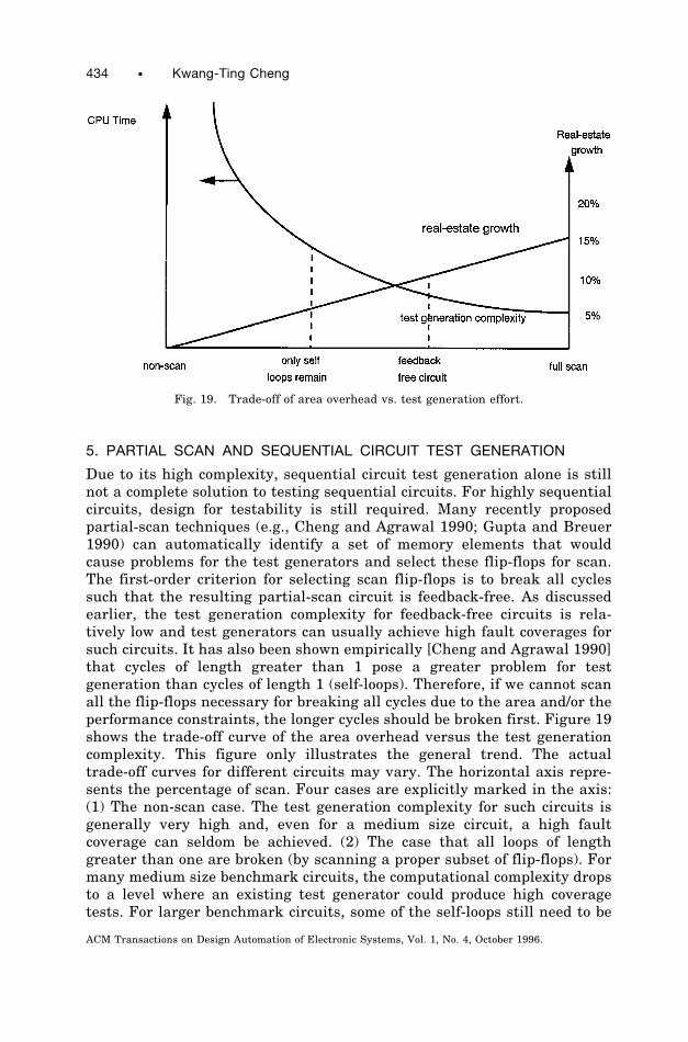
5. PARTIAL SCAN AND SEQUENTIAL CIRCUIT TEST GENERATION
Due to its high complexity, sequential circuit test generation alone is stillnot a complete solution to testing sequential circuits. For highly sequentialcircuits, design for testability is still required. Many recently proposedpartial-scan techniques (e.g., Cheng and Agrawal 1990; Gupta and Breuer1990) can automatically identify a set of memory elements that wouldcause problems for the test generators and select these flip-flops for scan.The first-order criterion for selecting scan flip-flops is to break all cyclessuch that the resulting partial-scan circuit is feedback-free. As discussedearlier, the test generation complexity for feedback-free circuits is rela-tively low and test generators can usually achieve high fault coverages forsuch circuits. It has also been shown empirically [Cheng and Agrawal 1990]that cycles of length greater than 1 pose a greater problem for testgeneration than cycles of length 1 (self-loops). Therefore, if we cannot scanall the flip-flops necessary for breaking all cycles due to the area and/or theperformance constraints, the longer cycles should be broken first. Figure 19shows the trade-off curve of the area overhead versus the test generationcomplexity. This figure only illustrates the general trend. The actualtrade-off curves for different circuits may vary. The horizontal axis repre-sents the percentage of scan. Four cases are explicitly marked in the axis:(1) The non-scan case. The test generation complexity for such circuits isgenerally very high and, even for a medium size circuit, a high faultcoverage can seldom be achieved. (2) The case that all loops of lengthgreater than one are broken (by scanning a proper subset of flip-flops). Formany medium size benchmark circuits, the computational complexity dropsto a level where an existing test generator could produce high coveragetests. For larger benchmark circuits, some of the self-loops still need to be
Fig. 19. Trade-off of area overhead vs. test generation effort.
434 • Kwang-Ting Cheng
ACM Transactions on Design Automation of Electronic Systems, Vol. 1, No. 4, October 1996.
broken by selecting more scan flip-flops. (3) The case that all loops,including self loops, are broken. (4) The full-scan case for which allflip-flops are scanned and a combinational test generator is used. The areaoverhead is roughly proportional to the percentage of scan and is estimatedby the straight line in the graph. To date, most of the ASIC designs still use100% full scan or a very high percentage of scan (a design point close to theright end of the horizontal axis). In the future, as sequential ATPGalgorithms continue to improve, the complexity curve will drop lower. Also,as the scan flip-flop selection algorithms improve, for the same percentageof scan, the test generation complexity will also drop. These trends shouldbe part of the driving forces for a wider acceptance of partial scan andsequential ATPG tools.
6. APPROACHES USING CIRCUIT MODELS AT HIGHER LEVELS OFABSTRACTION
Test generation could be significantly sped up if a circuit model at a higherlevel of abstraction is used. In this section, we discuss briefly the principlesof approaches using RTL models and state transitions graphs. Understand-ing the principles of such methods is helpful for the discussion of functionallearning to be discussed later. Because the main focus of this paper isgate-level approaches, we do not intend to give a detailed survey for suchapproaches but only a brief description of representative methods.
Approaches using register transfer level models. Approaches using RTLmodels have the potential to handle larger circuits because the number ofprimitives in an RTL description is much smaller than the gate count.Some methods in this class of approaches use only RTL description of thecircuit [Brahme and Abraham 1984; Cheng and Krishnakumar 1996;Hansen and Hayes 1995; Lee and Patel 1991; 1994; Thatte and Abraham1980] while others assume that both gate-level and RTL models areavailable [Hill and Huey 1977; Breuer and Friedman 1980; Ghosh et al.1990]. Note that automatic extraction of the RTL description from a lowerlevel of description is still not possible and therefore the RTL descriptionsmust be given by the designers. It is also generally assumed that data andcontrol are separated in the RTL model. For approaches using both RTLand gate-level models [Hill and Huey 1977; Breuer and Friedman 1980;Ghosh et al. 1990], typically a combinational test is first generated usingthe gate-level model. The fault-free justification sequence and the faultpropagation sequence are generated using the (fault-free) RTL description.Justification and fault propagation sequences generated in such a mannermay not be valid and therefore need to be verified by a fault simulator.These approaches, in general, are suitable for data-dominated circuits butnot appropriate for control-dominated circuits. For approaches using onlyRTL models [Thatte and Abraham 1980; Brahme and Abraham 1984; Leeand Patel 1991, 1994; Cheng and Krishnakumar 1996; Hansen and Hayes1995], functional fault models at RTL, instead of the single-stuck-at faultmodel at the gate-level are targeted. The approaches in Thatte and Abra-
Gate-Level Test Generation • 435
ACM Transactions on Design Automation of Electronic Systems, Vol. 1, No. 4, October 1996.
ham [1980] and Brahme and Abraham [1984] target microprocessors, andfunctional fault models are defined for various functions at the controlsequencing level. Tests are generated for the functional fault models andtherefore a high coverage for gate-level stuck-at faults cannot be guaran-teed. The methods suggested in Lee and Patel [1991, 1994] focus onminimizing the value conflicts during the value justification and faultpropagation processes using the high-level information. A recently pro-posed technique [Hansen and Hayes 1995] can guarantee that the func-tional tests for their proposed functional faults achieve a complete gate-level stuck-at fault coverage. This approach also uses an efficient methodfor resolving the value conflicts during propagation/justification at the RTlevel. A method of characterizing a design’s functional information using amodel extended from the traditional finite state machine model with thecapability of modeling both the data-path operations and the control statetransitions is suggested in Cheng and Krishnakumar [1996]. However, thismethod does not target any fault model and only generates functionalvectors for design verification.
Approaches using state transition graphs. For finite state machines(FSMs) for which the state transition graphs are available, test sequencescan be derived using the state transition information. In general, this classof approaches can handle only relatively small circuits due to the knownstate-explosion problem in representing a sequential circuit using its statetable. However, successful applications of such approaches to protocolperformance testing [Sabnani and Dahbura 1988] and to testing the bound-ary-scan Test Access Port (TAP) controller have been reported [Dahbura etal. 1989]. The earliest method is the checking experiment [Hennie 1964]which is based on distinguishing sequences. The distinguishing sequence isdefined as an input sequence that produces different output responses foreach initial state of the FSM. This approach is concerned with the problemof determining whether or not a given state machine is distinguishablefrom all other possible machines with the same or fewer number of states.No explicit fault model is used. The distinguishing sequence may not existand the bound on length, if it exists, is proportional to the factorial of thenumber of states. This method is impractical because of the long testsequence. Improved checking experiments, based on either the Simple I/Osequence [Hsieh 1971] or the Unique Input/Output (UIO) sequence [Sab-nani and Dahbura 1988] of the FSM, significantly reduce the test length. Afunctional fault model in the state transition level has recently been usedin a test generator FTG for FSMs [Cheng and Jou 1992]. In the single-state-transition (SST) fault model, a fault causes the destination state of asingle state transition to be faulty. It has been shown [Cheng and Jou 1992]that the test sequence generated for the SST faults in the given statetransition graph achieves high fault coverages for the single stuck-at faultsas well as the transistor faults in its multi-level logic implementation. Asan approximation, FTG uses the fault-free state transition graph to gener-ate the fault propagation sequence. AccuraTest [Pomeranz and Reddy
436 • Kwang-Ting Cheng
ACM Transactions on Design Automation of Electronic Systems, Vol. 1, No. 4, October 1996.
1991] further improves the technique and uses both fault-free and faultycircuits’ state transition graphs to generate accurate test sequences for theSST faults as well as for some multiple-state-transition faults.
7. SUMMARY AND CONCLUDING REMARKS
The presence of flip-flops and feedback loops substantially increases thecomplexity of the automatic test pattern generation problem. Due to theinherent intractability of the problem, it remains infeasible to automati-cally derive high quality tests for large, non-scan sequential designs.However, because of the great progress made during the past few years andthe availability of robust commercial ATPG tools, the partial-scan designmethodology that relies on such tools for test generation is becoming areasonable alternative to the full-scan design methodology.Like most other CAD tools, there are many engineering issues involved
in building a test generator to handle large industrial designs. Industrialdesigns may contain tristate logic, bidirectional elements, gated clocks, I/Oterminals, and so on. Proper modeling is required for such elements andthe test generation process also needs some modification. Many of theseissues are similar to those in the combinational ATPG problem that havebeen addressed by, for example, Breuer [1983], Ogihara et al. [1983], andChakradhar et al. [1995].Many sequential ATPG approaches try to extract some functional infor-
mation from the gate-level circuit description in the pre-processing phase.Such information, if properly used for value justification and fault propaga-tion, may save some unnecessary and/or repetitive computation during testgeneration. In Figure 20, we place several gate-level approaches in thehorizontal axis, according to the degree of functional learning conducted inthe pre-processing phase. To the very left, FTG [Cheng and Jou 1992] andAccuraTest [Pomeranz and Reddy 1991] extract the complete state transi-tion graph. For these approaches, complete functional knowledge (such asthe state transition graph) is learned and test generation is performedcompletely on the functional level. To the very right, STG3 [Cheng 1988]and HITEC [Niermann and Patel 1991] are mainly based on the gate-level information and no functional knowledge is pre-computed.STALLION [Ma et al. 1988] requires a (partial) state transition graphfor state justification but uses a gate-level description for fault propaga-tion. So the amount of functional knowledge learned in preprocessing isless than the amount learned by FTG and AccuraTest. STEED [Ghosh etal. 1991] computes and stores the ON and OFF sets of each statevariable in preprocessing and intersects the appropriate sets during testgeneration for both state justification and fault propagation. The degreeof learning is lower than STALLION.According to the reported results, FTG, STALLION, and STEED run
substantially faster than STG3 for some pure control circuits that have asmall number of flip-flops but have a relatively complex structure (i.e., eachnext state line or primary output is a function of most of the present state
Gate-Level Test Generation • 437
ACM Transactions on Design Automation of Electronic Systems, Vol. 1, No. 4, October 1996.
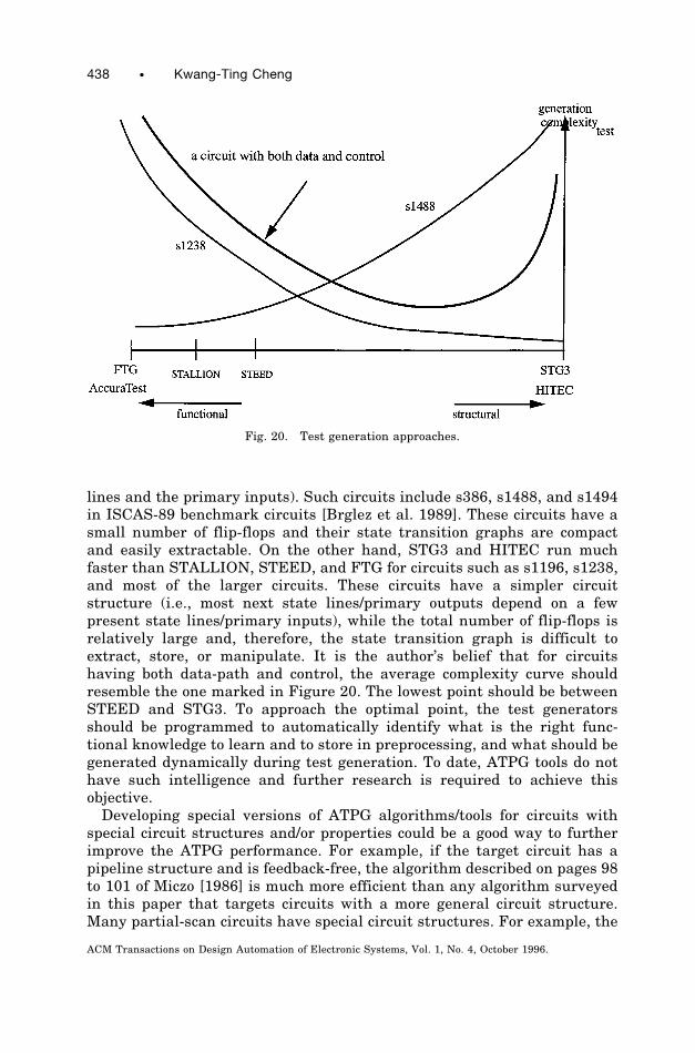
lines and the primary inputs). Such circuits include s386, s1488, and s1494in ISCAS-89 benchmark circuits [Brglez et al. 1989]. These circuits have asmall number of flip-flops and their state transition graphs are compactand easily extractable. On the other hand, STG3 and HITEC run muchfaster than STALLION, STEED, and FTG for circuits such as s1196, s1238,and most of the larger circuits. These circuits have a simpler circuitstructure (i.e., most next state lines/primary outputs depend on a fewpresent state lines/primary inputs), while the total number of flip-flops isrelatively large and, therefore, the state transition graph is difficult toextract, store, or manipulate. It is the author’s belief that for circuitshaving both data-path and control, the average complexity curve shouldresemble the one marked in Figure 20. The lowest point should be betweenSTEED and STG3. To approach the optimal point, the test generatorsshould be programmed to automatically identify what is the right func-tional knowledge to learn and to store in preprocessing, and what should begenerated dynamically during test generation. To date, ATPG tools do nothave such intelligence and further research is required to achieve thisobjective.Developing special versions of ATPG algorithms/tools for circuits with
special circuit structures and/or properties could be a good way to furtherimprove the ATPG performance. For example, if the target circuit has apipeline structure and is feedback-free, the algorithm described on pages 98to 101 of Miczo [1986] is much more efficient than any algorithm surveyedin this paper that targets circuits with a more general circuit structure.Many partial-scan circuits have special circuit structures. For example, the
Fig. 20. Test generation approaches.
438 • Kwang-Ting Cheng
ACM Transactions on Design Automation of Electronic Systems, Vol. 1, No. 4, October 1996.
partial-scan circuits using the cycle-breaking strategy to select scan flip-flops do not contain cycles with more than one flip-flop. Developing algo-rithms and tools to target circuits with such special circuit structures isworth pursuing.
ACKNOWLEDGMENTS
The author would like to thank M. Abramovici, V. D. Agrawal, W.-T.Cheng, S. Davidson, C. J. Lin, T. Ma, F. Maamari, I. Pomeranz, and S. M.Reddy for many useful discussions on sequential ATPG during the past fewyears, and A. Krstic for her helpful comments and many valuable sugges-tions. The author would also like to thank the anonymous reviewers whosecomments made the paper more balanced in the treatment of some topics.
REFERENCES
ABRAHAM, J. A. AND AGRAWAL, V. K. 1986. Test generation for digital systems. In Fault-Tolerant Computing Theory and Techniques, D. K. Pradhan, Ed. Prentice-Hall, EnglewoodCliffs, NJ.
ABRAMOVICI, M., BREUER, M. A., AND FRIEDMAN, A. D. 1990. Digital Systems Testing andTestable Design. IEEE Computer Society Press, Los Alamitos, CA.
AGRAWAL, V. D. AND CHAKRADHAR, S. T. 1995. Combinational ATPG theorems for identifyinguntestable faults in sequential circuits. IEEE Trans. Comput. Aided Des. 14, 9, (Sept.),1155–1160.
AGRAWAL, V. D. AND SETH, S. C. 1988. Tutorial—Test Generation for VLSI Chips. IEEEComputer Society Press, Ch. 3, Los Alamitos, CA.
BRAHME, D. AND ABRAHAM, J. A. 1984. Functional testing of microprocessors. IEEE Trans.Comput. C-33, 7, (July), 475–485.
BREUER, M. A. 1971. A random and an algorithmic technique for fault detection and testgeneration. IEEE Trans. Comput. C-20, (Nov.), 1366–1370.
BREUER, M. A. 1974. The effects of races, delays, and delay faults on test generation. IEEETrans. Comput. C-23, 10, (Oct.), 1078–1092.
BREUER, M. A. 1983. Test generation models for busses and tri-state drivers. In Proceedingsof the 1983 IEEE ATPG Workshop (March), 53–58.
BREUER, M. A. AND HARRISON, L. M. 1974. Procedures for eliminating static and dynamichazards in test generation. IEEE Trans. Comput. C-23, 10 (Oct.), 1069–1078.
BREUER, M. A. AND FRIEDMAN, A. D. 1980. Functional level primitives in test generation.IEEE Trans. Comput., (March), 223–235.
BRGLEZ, F., BRYAN, D., AND KOZMINSKI, K. 1989. Combinational profiles of sequentialbenchmark circuits. In Proceedings of the 1989 IEEE International Symposium on Circuitsand Systems (May), 1929–1934.
CHAKRADHAR, S. T., ROTHWEILER, S., AND AGRAWAL, V. D. 1995. Redundancy removal andtest generation for circuits with non-Boolean primitives. In Proceedings of the 13th IEEEVLSI Test Symposium, (April), 12–19.
CHAPPELL, S. G. 1974. LAMP: Automatic test generation for asynchronous digital circuits.Bell Syst. Tech. J., (Oct.), 1477–1503.
CHENG, K.-T. 1993. Redundancy removal for sequential circuits without reset states. IEEETrans. CAD, (Jan.), 13–24.
CHENG, K.-T. AND AGRAWAL, V. D. 1989. Unified Methods for VLSI Simulation and TestGeneration. Kluwer Academic, Norwell, MA.
CHENG, K.-T. AND AGRAWAL, V. D. 1990. A partial scan method for sequential circuits withfeedback. IEEE Trans. Comput. 39, 4, (April), 544–548.
CHENG, K.-T. AND JOU, J.-Y. 1992. A functional fault model for sequential circuits. IEEETrans. CAD, (Sept.), 1065–1073.
Gate-Level Test Generation • 439
ACM Transactions on Design Automation of Electronic Systems, Vol. 1, No. 4, October 1996.
CHENG, K.-T. AND KRISHNAKUMAR, A. S. 1996. Automatic generation of functional vectorsusing the extended finite state machine model. ACM Trans. Des. Autom. Electron. Syst. 1, 1(Jan.), 57–79.
CHENG, K.-T. AND MA, H-K. T. 1993. On the over-specification problem in sequential ATPGalgorithms. IEEE Trans. Comput. Aided Des. (Oct.), 1599–1604.
CHENG, W. T. 1988. The BACK algorithm for sequential test generation. In Proceedings ofthe 1988 IEEE International Conference on Computer Design (Oct.), 66–69.
CHENG, W. T. 1989. Private communications, Aug.CHO, H., HACHTEL, G. D., SOMENZI, F. 1993. Redundancy identification/removal and testgeneration for sequential circuits using implicit state enumeration. IEEE Trans. CAD(July), 935–945.
CHO, H., JEONG, S., SOMENZI, F., AND PIXLEY, C. 1993. Synchronizing sequences and sym-bolic traversal techniques in test generation. J. Electron. Testing, Theor. Appl. 4, 1, 19–31.
CORNO, F., PRINETTO, P., REBAUDENGO, M., REORDA, M. S., AND MOSCA, R. 1996. Advancedtechniques for GA-based sequential ATPGs. In Proceedings of the 1996 European Design andTest Conference, (March), IEEE Computer Society Press, 375–379.
DAHBURA, A. T., UYAR, M. U., AND YAU, C. W. 1989. An optimal test sequence for theJTAG/IEEE P1149.1 test access port controller. In Proceedings of the IEEE InternationalTest Conference (Aug.), 55–62.
DEVADAS, S., MA, H.-K. T., AND NEWTON, A. R. 1990. Redundancies and don’t-cares insequential logic synthesis. J. Electron. Testing, (Feb.), 15–30.
FUJIWARA, H. AND SHIMONO, T. 1983. On the acceleration of test generation algorithms.IEEE Trans. Comput. C32, (Dec.), 1137–1144.
GHOSH, A., DEVADAS, S., AND NEWTON, A. R. 1990. Sequential test generation at theregister-transfer and logic levels. In Proceedings of the 27th ACM/IEEE Design AutomationConference, (June), 580–586.
GHOSH, A., DEVADAS, S., AND NEWTON, A. R. 1991. Test generation and verification forhighly sequential circuits. IEEE Trans. Comput. Aided Des. (May), 652–667.
GLAESER, U. AND VIERHAUS, H. T. 1995. FOGBUSTER: An efficient algorithm for sequentialtest generation. In Proceedings of the European Design Automation Conference (EURO-DAC’95), (Sept.), IEEE Computer Society Press, 230–235.
GOEL, P. 1981. An implicit enumeration algorithm to generate tests for combinationalcircuits. IEEE Trans. Comput. C-30, (March), 215–222.
GOLDBERG, D. E. 1989. Genetic Algorithms in Search Optimization and Machine Learning.Addison-Wesley, Reading, MA.
GOLDSTEIN, L. H. 1979. Controllability/observability analysis for digital circuits. IEEETrans. Circuits Syst. CAS-26., (Sept.), 685–693.
GUPTA, R. AND BREUER, M. A. 1990. The ballast methodology for structured partial scandesign. IEEE Trans. Comput. 39, 4, (April), 538–544.
HANSEN, M. C. AND HAYES, J. P. 1995. High-level test generation using symbolic scheduling.In Proceedings of the IEEE International Test Conference, (Oct.), 586–595.
HENNIE, F. C. 1964. Fault-detecting experiments for sequential circuits. In Proceedings ofthe 5th Annual Symposium on Switching Circuit Theory and Logical Design, (Nov.), 95–110.
HILL, F. J. AND HUEY, B. 1977. SCIRTSS: A search system for sequential circuit testsequences. IEEE Trans. Comput. C-26, (May), 490–502.
HSIAO, M. S., RUDNICK, E. M., AND PATEL, J. H. 1996. Alternating strategy for sequentialcircuit ATPG. In Proceedings of the European Design and Test Conference (March), IEEEComputer Society Press, 368–374.
HSIAO, M. S., RUDNICK, E. M., AND PATEL, J. H. 1996. Automatic test generation usinggenetically-engineered distinguishing sequences. In Proceedings of the 14th IEEE VLSI TestSymposium, (April), 216–223.
HSIEH, E. P. 1971. Checking experiments for sequential machines. IEEE Trans. Comput.C-20, (Oct.), 1152–1166.
IYER, M. A. AND ABRAMOVICI, M. 1994. Sequential untestable faults identified withoutsearch. In Proceedings of the IEEE International Test Conference, (Oct.), IEEE ComputerSociety Press, 259–266.
440 • Kwang-Ting Cheng
ACM Transactions on Design Automation of Electronic Systems, Vol. 1, No. 4, October 1996.
KELSEY, T. P., SALUJA, K. K., AND LEE, S. Y. 1993. An efficient algorithm for sequentialcircuit test generation. IEEE Trans. Comput. 42, 11, (Nov.), 1361–1371.
KEIM, M., BECKER, B., AND STENNER, B. 1996. On the (non-)resettability of synchronoussequential circuits. In Proceedings of the IEEE VLSI Test Symposium, (April), 240–245.
KIRKLAND, T. AND MERCER, M. R. 1987. A topological search algorithm for ATPG. InProceedings of the 24th ACM/IEEE Design Automation Conference, (June), 502–508.
KUBO, H. 1968. A procedure for generating test sequences to detect sequential circuitfailures. NEC Res. & Dev., (Oct. 1968), 69–78.
LEE, D. H. AND REDDY, S. M. 1991. A new test generation method for sequential circuits. InProceedings of the IEEE International Conference on Computer-Aided Design (ICCAD-91),(Nov.), 446–449.
LEE, J. AND PATEL, J. H. 1991. A signal-driven discrete relaxation technique for architec-tural level test generation. In Proceedings of the IEEE International Conference on Comput-er-Aided Design, (Nov.), 458–461.
LEE, J. AND PATEL, J. H. 1994. Architectural level test generation for microprocessors. IEEETrans. CAD, 13, 10 (Oct.), 1288–1300.
MA, H-K. T., DEVADAS, S., NEWTON, A. R., AND SANGIOVANNI-VINCENTELLI, A. 1988. Testgeneration for sequential circuit. IEEE Trans. Comput. Aided Des., (Oct.), 1081–1093.
MARCHOK, T. E., EL-MALEH, A., MALY, W., AND RAJSKI, J. 1995. Complexity of sequentialATPG. In Proceedings of the European Design and Test Conference, (March), IEEE Com-puter Society Press, 252–261.
MARLETT, R. 1978. EBT, a comprehensive test generation technique for highly sequentialcircuits. In Proceedings of the 15th Design Automation Conference, (June), 332–339.
MICZO, A. 1986. Digital Logic Testing and Simulation, Harper and Row, New York.MUTH, P. 1976. A nine-valued circuit model for test generation. IEEE Trans. Comput. C-25,(June), 630–636.
NIERMANN, T. M., CHENG, W.-T., AND PATEL, J. H. 1992. PROOFS: A fast, memory-efficientsequential circuit fault simulator. IEEE Trans. CAD 11, 2, (Feb.), 198–207.
NIERMANN, T. AND PATEL, J. H. 1991. HITEC: A test generation package for sequentialcircuits. In Proceedings of the European Design Automation Conference, (Feb.), 214–218.
NITTA, S., KAWAMURA, M., AND HIRABAYASHI, K. 1985. Test generation by activation anddefect-drive (TEGAD). Integration 3, 12 (Dec.).
OGIHARA, T., MURAI, S., TAKAMATSU, Y., KINOSHITA, K., AND FUJIWARA, H. 1983. Test gener-ation for scan design circuits with tri-state modules and bidirectional terminals. In Proceed-ings of the 20th ACM/IEEE Design Automation Conference, (June), 71–78.
PIXLEY, C. 1990. A computational theory and implementation of sequential hardwareequivalence. In DIMACS Tech. Rep. 90-31. In Workshop on Computer-Aided Verification,vol. 2. AMS, Providence, R.I. 293–320.
PIXLEY, C. AND BEIHL, G. 1991. Calculating resettability and reset sequences. In Proceed-ings of the IEEE International Conference on Aided Design, (Nov.), 376–379.
PIXLEY, C., JEONG, S., AND HACHTEL, G. 1994. Exact calculation of synchronous sequencesbased on binary decision diagrams. IEEE Trans. CAD, 13, 8, (Aug.), 1024–1034.
POMERANZ, I. AND REDDY, S. M. 1991. On achieving a complete fault coverage for sequentialmachines using the transition fault model. In Proceedings of the 28th ACM/IEEE DesignAutomation Conference, (June), 341–346.
POMERANZ, I. AND REDDY, S. M. 1992. The multiple observation time test strategy. IEEETrans. Comput. 41, 5, (May), 627–637.
POMERANZ, I. AND REDDY, S. M. 1993. Classification of faults in sequential circuits. IEEETrans. Comput. 42, 9, (Sept.), 1066–1077.
POMERANZ, I. AND REDDY, S. M. 1994. On identifying untestable and redundant faults insynchronous sequential circuits. In Proceedings of the 12th IEEE VLSI Test Symposium,(April), 8–14.
POMERANZ, I. AND REDDY, S. M. 1995. LOCSTEP: A logic simulation based test generationprocedure. In Proceedings of the IEEE Fault Tolerant Computing Symposium, (June).
Gate-Level Test Generation • 441
ACM Transactions on Design Automation of Electronic Systems, Vol. 1, No. 4, October 1996.
PRINETTO, P., REBAUDENGO, M., AND REORDA, M. SONZA 1994. An automatic test patterngenerator for large sequential circuits based on genetic algorithm. In Proceedings of theIEEE International Test Conference, (Oct.), 240–249.
PUTZOLU, G. R. AND ROTH, J. P. 1971. A heuristic algorithm for the testing of asynchronouscircuits. IEEE Trans. Comput. C-20, (June), 639–647.
RHO, J., SOMENZI, F., AND PIXLEY, C. 1993. Minimum length synchronizing sequences offinite state machines. In Proceedings of the ACM/IEEE Design Automation Conference,(June), 463–468.
ROTH, J. P. 1966. Diagnosis of automata failures: A calculus and a method. IBM J. Res.Dev. 10, (July), 278–291.
RUDNICK, E. M., HOLM, J. G., SAAB, D. G., AND PATEL, J. H. 1994. Application of simplegenetic algorithms to sequential circuit test generation. In Proceedings of the EuropeanDesign and Test Conference, (March), 40–45.
RUDNICK, E. M. AND PATEL, J. H. 1995. Combining deterministic and genetic approaches forsequential circuit test generation. In Proceedings of the ACM/IEEE 32nd Design Automa-tion Conference, (June), 183–188.
RUDNICK, E. M., PATEL, J. H., GREENSTEIN, G. S., AND NIERMANN, T. M. 1994. Sequentialcircuit test generation in a genetic algorithm framework. In Proceedings of the ACM/IEEEDesign Automation Conference, (June), 698–704.
SAAB, D. G., SAAB, Y. G., AND ABRAHAM, J. A. 1992. CRIS: A test cultivation program forsequential VLSI circuits. In Proceedings of the IEEE International Conference on Computer-Aided Design, (Nov.), 216–219.
SAAB, D. G., SAAB, Y. G., AND ABRAHAM, J. A. 1994. Iterative [simulation-based genetics 1deterministic techniques] 5 complete ATPG. In Proceedings of the IEEE InternationalConference on Computer-Aided Design, (Nov.), 40–43.
SABNANI, K. AND DAHBURA, A. 1988. A protocol test generation procedure. Comput. Netw. 15,(April), 285–297.
SCHNURMANN, H. D., LINDBLOOM, E., AND CARPENTER, R. G. 1975. The weigthed randomtest-pattern generator. IEEE Trans. Comput. C-24, 695–700.
SCHULZ, M. H. AND AUTH, E. 1988. Advanced automatic test pattern generation and redun-dancy identification techniques. In Proceedings of the 18th IEEE International Symposiumon Fault-Tolerant Computing, (June), 30–35.
SCHULZ, M. H. AND AUTH, E. 1989. ESSENTIAL: An efficient self-learning test patterngeneration algorithm for sequential circuits. In Proceedings of the International TestConference, (Aug.), 28–37.
SCHULZ, M. H., TRISCHLER, E., AND SARFERT, T. M. 1988. SOCRATES: A highly efficientautomatic test pattern generation system. IEEE Trans. CAD, (Jan.), 126–137.
SESHU, S. 1965. On an improved diagnosis program. IEEE Trans. Electron. Comput. EC-14,2, (Feb.), 76–79.
SESHU, S. AND FREEMAN, D. N. 1962. The diagnosis of asynchronous sequential switchingsystems. IRE Trans. Electron. Comput. EC-11, (Aug.), 459–465.
SNETHEN, T. J. 1977. Simulator oriented fault test generator. In Proceedings of the 14thACM/IEEE Design Automation Conference, (June), 88–93.
SRINIVAS, M. AND PATNAIK, L. M. 1993. A simulation-based test generation scheme usinggenetic algorithms. In Proceedings of the IEEE International Conference VLSI Design,(Jan.), IEEE Computer Science Press, 132–135.
THATTE, S. M. AND ABRAHAM, J. A. 1980. Test generation for microprocessors. IEEE Trans.Comput., C-29, 6, (June), 429–441.
THOMAS, J. J. 1971. Automated diagnostic test program for digital networks. Comput. Des.,(Aug.), 63–67.
WEHBEH, J. A. AND SAAB, D. G. 1994. On the initialization of sequential circuits. InProceedings of the IEEE International Test Conference, (Oct.), 233–239.
Received January 1996; revised September 1996; accepted September 1996
442 • Kwang-Ting Cheng
ACM Transactions on Design Automation of Electronic Systems, Vol. 1, No. 4, October 1996.