Tutorial T11: Gas Turbine Air Filtration Systems For ...
25
Copyright© 2015 by Turbomachinery Laboratory, Texas A&M Engineering Experiment Station GAS TURBINE AIR FILTRATION SYSTEMS FOR OFFSHORE APPLICATIONS -Tutorial- Dominique Orhon Rainer Kurz Total Exploration and Production Solar Turbines Incorporated Stephen D. Hiner Jim Benson CLARCOR Industrial Air Camfill Farr Power Systems Dominique Orhon is a Senior Rotating Equipement Specialist at TOTAL Exploration&Production, in France. He has been with the business of turbomachinery design for more than 25 years. In 1988, he started working for the compressor and steam turbine manufacturer Thermodyn as a steam turbine designer and then joined the Oil&Gas Operator, TOTAL in 1991. He achieved design, construction, commissioning and start-up of two major offshore projects (30 000 bbl/d and 240 000 bbl/d) as Lead Mechanical and has been Rotating Equipement Head of Maintenance for TOTAL E&P Angola. Dominique is involved in turbomachinery design, integration in process, operation and trouble shooting and is specifically in charge of gas turbine qualification for Company. He is a Project Board Member of ETN (European Turbine Network) organization and is a Rotating Equipement lecturer at the IFP School (Institut Français du Pétrole) in Paris France. Dominique has published papers, presented panel sessions at International Conference. He is graduated from the Ecole des Hautes Etudes Industrielles (HEI), in Lille France with a Master’s Degree in Engineering. Dr. Rainer Kurz is the Manager, Systems Analysis, at Solar Turbines Incorporated in San Diego, California. His organization is responsible for analyzing compression requirements, predicting compressor and gas turbine performance, for conducting application studies, and for field performance testing. Dr. Kurz attended the Universität der Bundeswehr in Hamburg, Germany, where he received the degree of a Dr.- Ing. in 1991. He has authored numerous publications about turbomachinery related topics, holds two patents, is an ASME fellow, and a member of the Turbomachinery Symposium Advisory Committee. Stephen D Hiner is the Chief Engineer for Gas Turbine air filtration systems with Clarcor Industrial Air in the UK. He has been with the business for 20 years, through the Altair, General Electric and now Clarcor phases, gaining extensive experience and in-depth knowledge of; designing, developing and optimising air filtration solutions for Gas Turbines. Steve has published many papers and presented panel sessions at International Conferences, has numerous published and pending patents and is a member of the API 616 and ISO TC 142 task forces. He is a Chartered Engineer with the Institute of Mechanical Engineers IMechE and graduated from the University of Hertfordshire with a Bachelors Degree in Aerospace Engineering and a Master’s Degree in Engineering. Jim Benson is a senior product engineer with Camfil Farr Power Systems, North America. He has over 30 years of filtration experience, in the areas of product development, filter media and applications. This experience has covered multiple of markets including military vehicles, industrial dust collection and gas turbine systems. He has a bachelor’s of mechanical engineering, and Master in Management of Technology both from the University of Minnesota; and is a Professional Engineer. ABSTRACT Air filtration plays a key role in achieving high availability and low maintenance cost for Gas Turbines, in particular in offshore applications. Offshore applications pose a particular challenge, since they have to provide protection both against liquid water ingestion (and the salt particles dissolved in this water), as well as against very small particles (dry salt and other dust). Two fundamentally different concepts have emerged: High velocity systems and low/medium velocity systems, distinguished by the face velocity of the air entering the filter
Transcript of Tutorial T11: Gas Turbine Air Filtration Systems For ...
Copyright© 2015 by Turbomachinery Laboratory, Texas A&M Engineering Experiment Station
GAS TURBINE AIR FILTRATION SYSTEMS FOR OFFSHORE APPLICATIONS
-Tutorial-
Dominique Orhon Rainer Kurz
Total Exploration and Production Solar Turbines Incorporated
Stephen D. Hiner Jim Benson
CLARCOR Industrial Air Camfill Farr Power Systems
Dominique Orhon is a Senior Rotating
Equipement Specialist at TOTAL
Exploration&Production, in France.
He has been with the business of
turbomachinery design for more than
25 years. In 1988, he started working
for the compressor and steam turbine
manufacturer Thermodyn as a steam
turbine designer and then joined the
Oil&Gas Operator, TOTAL in 1991.
He achieved design, construction, commissioning and start-up
of two major offshore projects (30 000 bbl/d and 240 000
bbl/d) as Lead Mechanical and has been Rotating Equipement
Head of Maintenance for TOTAL E&P Angola. Dominique is
involved in turbomachinery design, integration in process,
operation and trouble shooting and is specifically in charge of
gas turbine qualification for Company. He is a Project Board
Member of ETN (European Turbine Network) organization
and is a Rotating Equipement lecturer at the IFP School
(Institut Français du Pétrole) in Paris France. Dominique has
published papers, presented panel sessions at International
Conference. He is graduated from the Ecole des Hautes
Etudes Industrielles (HEI), in Lille France with a Master’s
Degree in Engineering.
Dr. Rainer Kurz is the Manager, Systems
Analysis, at Solar Turbines Incorporated
in San Diego, California. His
organization is responsible for analyzing
compression requirements, predicting
compressor and gas turbine performance,
for conducting application studies, and
for field performance testing. Dr. Kurz
attended the Universität der Bundeswehr
in Hamburg, Germany, where he received the degree of a Dr.-
Ing. in 1991. He has authored numerous publications about
turbomachinery related topics, holds two patents, is an ASME
fellow, and a member of the Turbomachinery Symposium
Advisory Committee.
Stephen D Hiner is the Chief Engineer for
Gas Turbine air filtration systems with
Clarcor Industrial Air in the UK. He has
been with the business for 20 years,
through the Altair, General Electric and
now Clarcor phases, gaining extensive
experience and in-depth knowledge of;
designing, developing and optimising air
filtration solutions for Gas Turbines. Steve
has published many papers and presented
panel sessions at International Conferences, has numerous
published and pending patents and is a member of the API 616
and ISO TC 142 task forces. He is a Chartered Engineer with
the Institute of Mechanical Engineers IMechE and graduated
from the University of Hertfordshire with a Bachelors Degree
in Aerospace Engineering and a Master’s Degree in
Engineering.
Jim Benson is a senior product engineer
with Camfil Farr Power Systems, North
America. He has over 30 years of
filtration experience, in the areas of
product development, filter media and
applications. This experience has covered
multiple of markets including military
vehicles, industrial dust collection and gas
turbine systems. He has a bachelor’s of
mechanical engineering, and Master in
Management of Technology both from the University of
Minnesota; and is a Professional Engineer.
ABSTRACT
Air filtration plays a key role in achieving high availability and low maintenance cost for Gas Turbines, in particular in offshore applications. Offshore applications pose a particular challenge, since they have to provide protection both against liquid water ingestion (and the salt particles dissolved in this water), as well as against very small particles (dry salt and other dust). Two fundamentally different concepts have emerged: High velocity systems and low/medium velocity systems, distinguished by the face velocity of the air entering the filter

Copyright© 2015 by Turbomachinery Laboratory, Texas A&M Engineering Experiment Station
elements. While high velocity systems rely on vanes to remove liquids from the airstream, modern low/medium velocity systems use special filtration materials (usually in the last, high efficiency stage) that prevent water from passing through the element. Older systems did not have this type of filters available. The tutorial will discuss the physical principles of these air filtration concepts. The paper discusses the issues of filtration efficiency, dust holding capacity, as well as the capability to prevent water from entering the gas turbine. The discussion involves also the change in filtration characteristics over time. For the operator, it is important to understand the impact of the filtration system on engine degradation from fouling or hot corrosion, the frequency of intervention (water washing, change of filters), in conjunction with the operating conditions at site.
OVERVIEW
The goals of manufacturers and users of industrial gas turbine systems are generally well aligned: High availability and reliability, low performance degradation, and low maintenance requirements are high on the list. For offshore applications, weight and space requirements often play important roles. First cost has to meet project expectations. Gas turbines in offshore applications are expected to burn the available gas, with as little treatment as possible. In addition, the capability to run on liquid fuel, usually Diesel, during start-up and upset production is often required. The fuels in question may carry sulfur, especially the liquid fuel. Gas fuel may contain sulfur in the form of Hydrogen sulfide(H2S). Sulfur compounds in conjunction with salts can lead to hot corrosion in the hot section of the gas turbine. Several of these requirements are managed by appropriate air filtration (Brekke et al, 2009, Vigeland, 2005). Gas Turbine filter performance is defined in ASHRAE and EN specifications (Table 1). Gas Turbines ingest large amounts of air. For example, a 30,000 hp class industrial gas turbine ingests 250 tons of air per hour, equivalent to over 3000 m3/min. If the dust load of the air is 1ppm, an unprotected engine would ingest 250 g of dust every hour, or over 2000 kg of dust per year. If an engine ingested 2000kg/year of contaminants if there were no filtration system in a typical off shore application, an F5 filter would reduce this to about 420 kg/year, an F6filter to 120kg/year, a F7/E10 filter system to 4kg/year and a F7/F9/E10 system to as little as 1 kg/year (EN779, 2012). So far, we assumed solid particles. However, liquid droplets can also carry contaminants (salts, for example). A filter system therefore has to be capable to not only protect the engine from solid particles, but also prevent the ingestion of liquids. Some of the contaminants will stick to compressor airfoils and flow passages, causing fouling. Some may cause erosion. Some particles will melt in the combustor, and may fuse to surfaces. Others may react with fuel contaminants like sulfur, generating corrosive salts. In any case, ingested materials will cause the gas turbine to lose performance, and it may shorten maintenance intervals. The efficiency of the air filtration system, for a given environmental situation therefore impacts
degradation rates as well as availability and reliability of the engine. On the other hand, the air filtration system is a cost factor by itself. Offshore applications are often sensitive to space requirements and weight. Air filters have to cleaned or replaced, and, depending on the type of system, may require engine shutdowns for these maintenance events.
Table 1. Summary of filter classifications for ASHRAE 52.1,
52.2, EN 779:2012, and EN 1822:2009. The air filtration systems also causes a pressure drop, that usually increases once the filter starts to accumulate dirt. The pressure drop reduces the engine output (Figure 1). Since the pressure drop of the filter system is related to face velocity, as well as filtration efficiency, there are trade-offs between filter size, weight and cost on the one hand , filtration efficiency and pressure drop, and rate of engine degradation.
Figure 1: Impact of inlet pressure loss on engine power and
heat rate

Copyright© 2015 by Turbomachinery Laboratory, Texas A&M Engineering Experiment Station
OIL&GAS OFFSHORE SITE CHARACTERISTICS
Gas turbine Applications Gas turbines are widely used offshore because this type of product provides a high power output for a limited weight and footprint. It is far better on this standpoint than the gas or diesel engine. Aero-derivative and industrial engine design is often preferred over heavy duty engines because they offer the possibility to overhaul the engine in a work shop with a quick and easy engine exchange. Mechanical Drive.
Gas turbines drive compressors, essentially centrifugal compressors which pressurize gas used for flash gas compression, for the gas-lift for wells or risers, for gas export to shore for treatment and liquefaction or for gas injection in the field. Gas turbines also drive centrifugal pumps for water injection in the field to maintain the reservoir under pressure. Power Generation.
Gas turbines drive generators from a few hundred kilowatts to a few tens of megawatts. Generally, these are dual fuel gas turbines not connected to the grid running in a droop mode.
Locations
The offshore assets producing oil, gas or both may be spread over different climatic regions. For instance, the following regions which have very different characteristics, are operated, for example:
• The boreal windy and harsh North Sea region.
• The tropical humid Gulf of Guinea with seasonal wind-blown dust.
• The rainy Far East region.
• The salty Persian Gulf in the Middle East.
• Gulf of Mexico, with a wide range of salinity and humidity
The offshore assets can be fixed leg or tension leg platforms, FPUs (Floating Production Unit) or FPSOs (Floating Production Storage and Offloading Unit). Atmospheric salt concentrations (Figure 2, McGuigan, (2004)) vary significantly geographically and from season to season. In addition, the relative humidity of the air is also subject to regional and seasonal changes.
A useful differentiation for gas turbine operation is the distinction between land based, coastal, offshore and marine applications. There are three categories of environments to consider in relation to inlet air contamination with salt: Marine, Offshore, and Coastal. While somewhat arbitrary, it allows to focus on distinguishing features. Offshore and Marine environments are often used interchangeably, but we often have to distinguish between applications at different elevations from sea level. Note that there are also inland sites where significant amounts of salt are present. Examples are certain deserts, dried lakes, and certain industrial sites. These types of environments should be thoroughly evaluated, and should be treated as coastal when salt levels are determined to be significant.
Figure 2: Atmospheric sea-salt concentration distributions during the boreal winter (December, January and February)-top, and the boreal autumn (September, October and November)-bottom (McGuigan, (2004)).
Marine - This classification includes marine applications where the inlet to the filtration system is located within 30 meters (100 feet) from the ocean surface. Applications include some FPSO’s, gas turbines used for marine propulsion, semi-submersibles, etc., where the air filter may be subjected to green water. Offshore - This classification includes offshore applications where the filtration system is more than 30 meters(100 feet) above the ocean surface. The environmental conditions are the same as the marine classification above, but the air filters will not be subjected to green water. Coastal -This classification includes any land-based application within 10 miles of a coastline. Coastal applications face, as far as filtration goes, similar challenges as offshore applications, since they are subject to both land based dust, and sea borne salt. The Marine and Offshore Environment All Gas Turbine (GT) inlet filters are designed to deal with the common types of contaminants such as; sand, dust and soot. Operation in the marine environment brings its own additional contaminant challenges that must be addressed by the GT filtration system to maintain a reliable and available machine, the main ones being discussed below. Salt Aerosol
Salt aerosol is the mixture of very small particles or droplets of salt with the surrounding air. This is formed when waves trap air as bubble, which rise through the sea to its surface

Copyright© 2015 by Turbomachinery Laboratory, Texas A&M Engineering Experiment Station
where they burst expelling small droplets into the atmosphere (Figure 3).
Figure 3 top : Bubbles in the sea bottom: Wave action
The amount and make-up of these aerosols is a function of the wind and sea states. Strong winds lead to more and larger droplets. The resulting form of the salt within the aerosol when it eventually reaches the gas turbine inlet is directly related to the ambient relative humidity. At relative humidity’s (RH) below ~40%, salt is crystal and can be considered as a dry particulate and can therefore be filtered just like any other dust type particle with traditional filtration methods. Complications arise when the relative humidity changes as salt crystals are hygroscopic in nature, i.e. they have an affinity for water and like to absorb moisture from the surrounding air (Figure 4).
Figure 4 Change in salt state with humidity (Gas Turbine
Design Handbook, 1983)
At a critical relative humidity (~70% RH, Figure 4, the salt crystal will continue to absorb moisture (and swell accordingly) until it reaches super saturation, at which time it deliquesces. Deliquescence is the change undergone by certain substances, which become damp and finally liquefy when exposed to the air, owing to the very low vapour pressure of their saturated solution. Salt is such a substance. At this critical RH the salt crystal becomes a saline droplet, which requires different filtration methods to capture and retain it. At a relative humidity between 40% and 70%, the salt crystal is neither completely ‘wet’ nor completely ‘dry’ and can be considered as dynamic or ‘sticky’. The RH at the surface of
the sea approaches 100% and has a vertical distribution with height which is dependent upon wind velocity. Offshore operators with meteorological capabilities have recorded frequently and regularly varying relative humidity, often below the 70% RH level where salt begins to change from wet droplet to dry crystalline. Consequently, a gas turbine inlet air filter system design for coastal, marine and offshore installations must be able to handle salt in its wet, dry and dynamic phases (Figures 4 and 5). When salt reaches a gas turbine, it can foul and corrode the compressor section, but more importantly, the sodium in the salt combines with the sulphur in the fuel (if present) to cause highly accelerated corrosion in the hot section of the GT (Stalder etal, 2001).
Figure 5: top: Dry salt, center: Salt crystal, bottom: Wet salt.
Bulk Water
Bulk water is the mixture of large quantities of water with relatively large droplet sizes within the air entering the GT filtration system. This can be generated by heavy seas in the form of waves and spray, spray from the motion of vessels or produced by the weather, such as driven rain from heavy storms, monsoons etc. It can even come from man-made sources, such as on board fire deluge systems etc.

Copyright© 2015 by Turbomachinery Laboratory, Texas A&M Engineering Experiment Station
Figure 6: Sea spray Large quantities of water entering the filtration system can cause the filter pressure loss to rapidly increase, due to over loading and filter plugging or blockage due to the expansion of captured dust via the soaking up of moisture. It can also cause captured dirt and salts to be washed off and through the filters further downstream of the system. I the water is able to pass the filters, then the large size of the droplets have the real potential to do damage to the rotting parts of the gas turbine (Figure 6). Mist and Fog
Mist and fog is another form of aerosol, but this time is in the form of fine pure water droplets in the airstream, typically with a droplet size of less than 2 microns in diameter (Figure 7). On its own, this type of contaminant is small enough and chemically inert to be harmless to a GT, but it can have affects upon the filtration system itself, causing the swelling of captured contaminants leading to high pressure losses, or even pressure loss “spikes” during fog periods. This affect can be greatly exaggerated if the filters also experience contamination from hydrocarbons, such as from lube oil vent outlets etc. and can also be more pronounced with higher efficiency filters.
Figure 7: Mist and Fog
Figure 8: Hydrocarbon vapours As with bulk water, the wetting of the filters can lead to contaminant being washed through and further downstream. Other Contaminants
The air at the gas turbine intake can also be contaminated by products of normal platform operation, such as hydrocarbon vapors (Figure 8), dust from well completions, drilling mud and others.
OPERATING CONDITIONS Offshore operations are 24/7, 365 days a year. Complete plant shutdown is normally not desired. Therefore, inspection and maintenance are carried out by sector and this generates a temporary decrease in production. A planned shut-down of the whole asset may happen if the different tasks are spread over the asset process but in any case it will not necessarily be an annual shut-down. Gas Turbine Load
Generally, it is a full load running condition for mechanical drive application despite being suitably sized. The highest production rate is expected from the assets. Therefore all margins necessary for design (ageing, fouling, temperature sizing, driven equipment API tolerance) are absorbed. This allows a slightly higher production of oil or gas. Power generation applications are operated part load to satisfy the load balance, and to create a spinning reserve for upset conditions. Offshore assets are not connected to the grid. In consequence, any extra power produced is not exported.
High Availability Requirement
Power generation is considered a utility. Consequently, machines to provide power are redundant in order to reach an availability close to 99.9% on the power function. Usually, one turbine is used as a stand-by. The gas turbine arrangement is composed of 3x50% or 4x33%. It is quite unusual or inefficient to install a 2x100% power generation. This obliges the operation team to run two gas turbines or to lose the asset if only one gas turbine is running. Generally, compression or pumping functions are not spared. Gas turbine arrangements are 1x100%, 2x50% or 3x33%. For a mechanical drive application, the availability of the shaft-line is 97.5% on average with sweet gas. Off-line washing is not particularly appreciated off-shore by the operating team because it

Copyright© 2015 by Turbomachinery Laboratory, Texas A&M Engineering Experiment Station
impedes the availability of the equipment by 0.2%. Offshore gas turbine down time is very costly. A gas turbine at rest may represent a few million US dollars loss of production per day. Therefore, availability is a key driver for rotating equipment.
Long Term Operation
In order to reach the maximum availability, gas turbines are operated through long runs without stopping the engine. A stop may be required to balance the running hours between the different machines in order to maintain a suitable slot for overhaul. Maintenance
Planned maintenance is the maintenance principle off-shore on gas turbines. The maintenance crew at site is limited due to POB (Personnel On Board) constraints. In addition, it is always difficult to mobilize complementary maintenance staff for dedicated operations for the same reason. Some assets are quite far away and this fact generates a tremendous turnaround time for gas turbine overhaul. This may reach 6 months for some countries. Some assets are now equipped with remote diagnosis tools which allow us to monitor equipment without actually being on the offshore installation.
Installation Conditions Limited Foot Print
All equipment installed offshore must have a limited footprint. Offshore installations are usually congested. It is always beneficial to find space-saving solutions. Air filter solutions may help to solve this problem. Limited weight
Any extra weight has to be accommodated by supporting structure reinforcement or by any solution that increases the buoyancy of the floating production unit. Weight savings are always sought at the design stage. No craneage
On some installations, operating a crane above the platform equipment is not allowed. For safety reasons, no craneage is available above live equipment using hydrocarbons. Therefore it is quite common to see no cranes above a gas turbine air filtration system. A change of air filter housing must be carried out by an external crane barge. Nevertheless, some platforms or floating units are equipped with cranes. Single-lift loading
In order to limit the impact on operations, any lift on an offshore asset needs to be a single lift loading. No stickbuilt assembly by crane barge is foreseen on principle.
AIR AND FUEL CHARACTERISTICS
Air Characteristic The gas turbine air intake may ingest different components not necessarily anticipated when the air filtration was designed. Offshore air quality is also highly dependent on the close surroundings. Therefore, it is very important to take care with the choice of direction of the air inlet filtration system and to ensure that it is towards the prevailing wind. An air inlet filter must not be closed by the exhaust of other equipment
Sodium from Sea Water
Sodium is an alkali which is very detrimental to the gas turbine when H2S or Sulfur are components of the fuel. Hot corrosion may take place on the hot path section. Sodium is conveyed from the sea by the wind. It is carried in the gas turbine air inlet filter in different forms: solid, wet or dissolved in water. It is quite common to collect this salt on the axial compressor as shown on the blades hereafter (Figure 9). Salt (and other chlorides) in combination with moisture are primarily responsible for metal surface pitting in gas turbine compressors. As one of the most common deposits, salts lead to the formation of the deposit of chlorides in microscopic surface cracks and subsequent subsurface corrosion (evidenced as characteristic pits (small holes) on the surface of the blades. Salts can enter the gas turbine with the ambient air or could be introduced with the fuel (especially liquid fuel), Salt, as well as any dust entering the compressor section, may also stick to the compressor surfaces (‘fouling’), and cause the compressor perfromance to deteriorate.
Figure 9: Salt Deposit on the blades of an axial compressor. Potassium from Drilling Mud
Potassium is also an alkali which may impact the gas turbine hot path section. Drilling operations are regularly carried out on well platforms. These drilling operations generally use barium but may also use potassium chloride. Potassium powder is the ingredient to fabricate drilling mud. This powder may fly close to the gas turbine in operation. Oil Smoke (Lube Oil Vapor and Mist).
Elementary sources of oil smoke are found on an offshore asset. Rotating machinery running on a lube oil system is equipped with a lube oil mist vent. An oil mist eliminator can be fitted on the lube oil vent or not. This allows a reduction in the oily mist quantities by running the system slightly under vacuum. It increases the condensation of the liquid portion of the mist (Figure 8). Nevertheless, the remaining mist may be taken in by the gas turbine air intake if the exit of the vent is located in the vicinity of the gas turbine filter housing.
Oils and Waxes: Oils and waxes are usually residues from compressor washing or ambient air contamination. Generally, the components do not cause significant damage but can act as binding agents for dirt or sand in the compressor and, thus, can contribute to fouling.

Copyright© 2015 by Turbomachinery Laboratory, Texas A&M Engineering Experiment Station
Carbon Black and Soot
The soot is made up of particles from 0.02 to 0.4 micrometers in size. Diesel engine exhaust generates particles from 0.003 to 0.5 micrometers in size. Carbon black is particles 0.01 to 0.4 micrometers in size. The sources of carbon black or soot are the exhaust fumes of the gas turbine, gas engine or diesel engine. Supply boats delivering their goods to the offshore assets can be an additional source of exhaust fumes passing in front of the gas turbine air intake. Carbon (or coke) deposits on compressor blades indicate that exhaust gases from the gas turbine or other internal combustion engines are entering the axial compressor. Coking inside the rotor can also be caused by local overheating or lube oil leakage. Deposits will bind with oils to form a surface deposit on the blades, which is very hard to remove with online and offline cleaning. Most will deposit in the first couple of stages of the compressor and will not be carried downstream. Wind-blown Dust
Wind-blown dust is generally a seasonal phenomenon offshore. It is made up of sediment or deposits. Quantities carried at high altitude could be quite significant and can progress over thousands of kilometers. This fine dust from 1 to 100 micrometers in size may go into all equipment even if it is sealed. For instance, in the Gulf of Guinea region, the Harmattan is a trade wind impacting gas turbine operations for 3 to 4 months from November to March. In the Gulf of Guinea, for example, Saharan dust or Namibian desert dust may be found and carried out offshore as well. For example, particles found on the floor of an air filter housing installed on an offshore Guinea Gulf asset were analyzed by X-Ray fluorescence spectrometry. Silica (SiO2 40% weight), aluminum (Al2O3 19%), calcium (CaO 19%), iron (Fe2O3 4%), magnesium (MgO 2%) and potassium (K2O 2%) were found predominantly. After removing particles over 212 micrometers in size, the particle sizing distribution was measured with a laser particle size analyzer showing a peak at 10 micrometer particles (Figure 10).
Figure 10: Wind Blown Dust - Particle Sizes
Dirt: Sand and other types of dust (for example from farming, industrial processes, drilling, but also from dust storms.) are primarily introduced into the gas turbine through the inlet filter and is an indication of inadequate inlet filtration or filter
dirt saturation. In general, this is more of in issue for coastal and near shore installations. But, as outlined above, can affect even installations for away from the coastline.
Grit and Paint Dust
Due to heavy corrosion offshore, painting is a regular task. It affects all the parts of an asset (plain decks, piping, structure, equipment). Before applying paint, surfaces must be thoroughly cleaned. Old paint is removed by brush tooling or by blasting. Grit made of mineral or metallic abrasives is generally used for blasting. Paint mist
Paint mist (from 0.1 to 100 micrometers in size) also takes place offshore during the painting campaign. Sufur Dioxide SO2
Some fuel gas contains hydrogen sulfur (H2S) and some liquid fuel contains sulfur (S). The stoichiometric combustion of H2S generates SO2 in the exhaust fumes as per the following equation:
2 H2S + 3 O2 => 2 SO2 + 2H2O This SO2 can be an additional component of carbon black and soot. Humidity
Humidity may stay offshore in the form of a mist (from 1 to 30 micrometers in size), drizzle (from 30 to 300 micrometers in size) or rain drops (300 micrometers and over in size). Humidity may convey aqueous salt less than 0.001 micrometer molecules. Welding fumes
Hot work like welding is regularly carried out on an offshore asset. This hot work covers repairs, improvements or development requirements and generates particles (from 0.001 to 100 micrometers in size).
Fuel Characteristics Offshore, air filtration cannot be considered without paying close attention to the fuel characteristics. Fuel gas comes essentially from the associated gas (in oil fields), or the field gas (in gas fields). Its quality and composition is related to the reservoir characteristics. Liquid fuel is generally a diesel oil DMX or DMA quality according to the ISO 8217. Air and fuel combustion are key factors impacting the gas turbine integrity. Therefore, the choice of an air filtration is considered as dependent on the fuel quality.
Gas Fuel Associated Gas
Fuel gas is obtained from the production separation gas. This gas passes through a fuel gas treatment unit composed of a fuel gas receiver, a filter, a coalescer and a heater. Different Gas Sources
For the same asset the gas can come from different wells having different qualities. On the topside treatment units, the fuel gas may be taken from the crude oil first stage separator or from the gas compression units. Fuel gas before the treatment unit may be dry or totally wet. H2S Content.
It is quite common to recover sour gas from a reservoir. The content of H2S may vary widely from a few ppm to a few tens
0
20
40
60
80
100
0
5
10
15
20
25
0,01 0,1 1 10 100 1000
Cu
mu
lati
ve
ov
ersi
ze (
%)
Dif
fere
nti
al
ov
ersi
ze (
%)
Size (µm)
Differential
Cumulative

Copyright© 2015 by Turbomachinery Laboratory, Texas A&M Engineering Experiment Station
of percent. It is particularly expensive and power consuming to remove the H2S from gas. This removal necessitates the installation of a complex amine treatment unit. In addition, the total removal is not complete and the remaining H2S content is close to 20 ppm. Wet Gas
On an oil production platform, three phases are generally produced: oil, water and gas. Consequently, gas used for fuel gas is wet. Fuel gas needs to be treated to offer a sufficient margin with the water and hydrocarbon dew point. This is generally 50°F. Saturated Gas
In the same way, the gas for gas turbines needs to be heated in order to maintain 50°F above the hydrocarbon dew point. Methanol or Tri Ethylene Glycol (TEG)
Methanol or TEG is dissolved in the gas. Gas may be saturated with one of these two components or both. These traces may impact the behavior of the fuel gas heavily by creating TEG or MeOH saturation curves appearing at a higher temperature than the hydrocarbon or water saturation curves.
Liquid Fuel Usually, the power generation application uses liquid fuel for startup purposes. The objective is to provide sufficient power in order to open the wells and allows oil and gas to pass through the separation process. When the process is established, fuel gas can be produced and the gas turbine(s) is (are) transferred from liquid fuel to fuel gas. The different startup operations may require one or two hours on a large asset. Therefore, running on liquid is very limited in time. Diesel
The liquid fuel most frequently used in offshore gas turbine applications is diesel. Different specifications for this fuel limit the amount of sulfur to certain levels. These limits are different in different countries and different parts of the world. DMX or DMA Diesel Oil contains sulfur, from 1% max for DMX to 2% max for DMA, while low sulfur diesel contains less than 15ppm sulfur.
Diesel oil quality varies widely. Especially, Diesel oil is prone to aging, with the possibility of hydrocarbon recombination. All diesel oils are not necessarily hydrogenated and do not come from a straight distillation. In consequence, many components are part of the diesel oil such as heavy ends, colloids, asphaltenes, sulfur, etc. Diesel oil quality is also highly dependent on the production area and also on the supply chain to site. It is quite common in some areas for some diesel oil batches to be altered or polluted by the carriers (tankers, vessels, supply boats), which deliver at site. The final quality may then be questionable.
MECHANISMS OF GAS TURBINE DEGRADATION.
General Considerations on Gas Turbine Degradation
Several mechanisms cause the degradation of engines (Kurz et al., 2008):
• Fouling
• Corrosion, hot corrosion, and oxidation
• Erosion and Abrasion
• Particle Fusing
• Mechanical Degradation.
Of these, fouling, erosion, corrosion as well as hot corrosion are related to the quality of the air filtration system. Fouling is typically related to small particles as well as water ingress, while corrosion and hot corrosion require the presence of salt particles or droplets. Erosion effects require the presence of droplets or particles larger than 5 to 10 microns. In other words, the air filtration system must control the amount of small particles and large particles, as well as the ingress of water droplets with dissolved salt.
Fouling is caused by the adherence of particles to airfoils and annulus surfaces. The adherence is increased by oil or water mists. The result is a build-up of material that causes increased surface roughness and, to some degree, changes the shape of the airfoil. Particles that cause fouling are typically smaller than 2 to 10 µm. Smoke, oil mists, carbon, and sea salt are common examples. Fouling can be controlled by an appropriate air filtration system. Fouling can often be reversed to some degree by detergent washing of components. Fouling in the colder sections of the engine can normally be eliminated by cleaning. Components operating at elevated temperatures are also subject to fouling, but the dirt will often be baked to the surfaces, and can usually not be removed by cleaning processes available in the field. Compressor fouling is quite common offshore despite being at a few hundred kilometers from the shore. Fouling is quite usual and made up of very small particulates, greasy hydrocarbon molecules and unburned components coming from exhaust fumes (Figure 11).
There are generally four different types of fouling deposits that can be found inside an axial compressor: salts, heavy hydrocarbons (oils and waxes), carbon dirt, and other dirt. Morini etal (2011), Suman et al (2014a), Suman et al (2014b), and Kurz etal (2012) discuss the mechanisms that cause these very small particles to hit blade surfaces, and stick to these surfaces. A gas turbine compressor acts like a very effective air filter in that it collects and deposits a significant percentage of any solids that are carried by the ambient air and are ingested into the gas turbine inlet. Also, due to the heat of compression, the temperature of the air passing through the
compressor will increase to above 315°C ( 600°F) such that any solids or chemicals dissolved in the water will drop out and deposit on the compressor blades.

Copyright© 2015 by Turbomachinery Laboratory, Texas A&M Engineering Experiment Station
Air contamination can be significantly reduced by the use of more efficient air filtration systems, especially those that reduce the quantity of smaller particles ingested. Therefore, it is essential that the air filtration system be optimized to remove small particles, while also being capable of protecting against larger contaminants. Many improved media filter elements can be used as replacement elements during filter change-out. Filter companies have developed media to capture more dust particles in the 0.1 to 2 µm size range, while still offering satisfactory filtration of larger particles and acceptable service life. However, generally speaking, the more efficient the filtration efficiency of small particles, the higher the pressure loss across the inlet system, or the larger the filtration system becomes.
Figure 11: Compressor Fouling. Bottom Picture:Fouling due
to Carbon Black Deposit.
Composition of the particles is important in determining the rate of fouling. Because of very high mass flows, even very low levels of ingested foreign material can produce a substantial input of contaminants through gas turbine engines (see discussion above). For example, 1 ppmw of impurities entering the gas turbine results in over 4500kg of ingested material for a Frame 5 type gas turbine over an 8,000-hour operating period. Even after several stages of cleanup (including barrier filters) of ambient inlet air, deposits commonly form in gas turbine compressors due to ingested particulate so that compressor washing is periodically needed to restore efficiency by removing deposits. Details on compressor fouling may be found in Meher-Homji et al (2009), Kurz et al (2013) and Kurz et al 2012.
In many instances, operators base maintenance interventions on measured performance deterioration, for example when the loss of power reaches 10 to 15 percent of the expected output power or the loss of efficiency reaches 10 points of the expected efficiency. Corrosion is the wearing away of surface metals due to a chemical reaction of the metal with the environment (unlike erosion or fretting which are mechanisms of the wearing away of surface metal due to mechanical surface action). Usually the metal reacts with oxygen in the air but there are many other chemical reactions that can participate in the different corrosion mechanisms. Certain types of corrosion (such as oxidation, sulfidation, and hot corrosion) are mainly attacking the hot section of the gas turbine. Other types, such as crevice corrosion and pitting, are rather found in the compressor section of the gas turbine. For gas turbine applications the most important corrosion mechanisms are (Brun et al, 2010): Oxidation, type 1 hot corrosion, type 2 hot corrosion, corrosion pitting, and crevice corrosion. These mechanisms are relevant for gas turbines and can impact their life and performance.
Figure 12: Axial Compressor Corrosion.
Offshore, it is common to observe compressor corrosion. This is generally seen as pitting taking place on compressor blades (Figure 12). Some gas turbines, such as heavy duty gas turbines or industrial gas turbines are more sensitive to corrosion even if some coatings (or marinization) are available to offer a better protection. These machines cannot offer the corrosion resistance of aero-derivative gas turbines whose compressor blades and vanes are made of titanium. For any given location, the operating configuration may also amplify the corrosion process. Gas turbines backed-up with hot stand-by units display a stronger tendency to corrosion.
Corrosion can be caused both by inlet air contaminants and by fuel, water, or combustion derived contaminants. Fuel side corrosion is typically more noted and severe with heavy fuel oils and distillates than with natural gas because of impurities and additives in the liquid fuels that leave aggressive deposits after combustion. Salt-laden air can also cause corrosion on unprotected engine parts. Corrosion Pitting, also simply called “pitting,” this is a localized corrosion mechanism that

Copyright© 2015 by Turbomachinery Laboratory, Texas A&M Engineering Experiment Station
leads to the formation of small but deep holes in the metal surface. As these holes are often not detected because the remainder of the metal part may appear completely clean, shiny, and polished, they represent a significant danger for unexpected failures. Pitting is often found on gas turbine compressor blades and it is caused by the intrusion of conductive impurities, such as salt water, into small surface cracks in the metal surface. As the water evaporates, the concentration of the impurity (usually sodium, sulfate, or chloride) increases, which results in highly localized corrosion and consequent deepening of the cracks. This process continues until a deep crack forms, metal pieces break off, and a pit (or hole) is formed. The pit can severely weaken the blade and also cause stress concentrations. Pitting can be initiated by very small microscopic surface defects or scratches, which are often not visually detectable. Most often, pitting on compressor blades occurs in gas turbine application where salt is ingested into the compressor (from the inlet air) and if the unit‘s operation is highly cyclic with many starts and stops. During any prolonged shutdown, water condensate forms on the blades, dissolves the blade salt deposits, and then enters into microscopic surface cracks to initiate the pitting process. To limit compressor blade pitting, anti-corrosive blade coatings can be utilized, and the axial compressor should be thoroughly water washed before any extended shutdown period (to remove salt deposits), and the inlet filtration system should be designed to minimize salt intrusion.
The physical process of crevice corrosion is similar to pitting, but rather than inside metal surface cracks, crevice corrosion occurs in pre-existing tight gaps, such as contact areas between parts, underneath grout, seals, and gaskets, or below hardened dirt or blade foulant. Concentration factors of impurities in these crevices can reach several millions. Because these areas cannot easily be inspected without disassembly, crevice corrosion presents a substantial risk of catastrophic failure. In gas turbines, crevice corrosion at the highly stressed mating surfaces between rotor blade base and disk slots can go undetected for years until either the blades are disassembled (which is usually not done unless the gas turbine is repaired/overhauled) or the blade structural support fails and they are liberated into the gas path (resulting in domestic object damage).
Corrosion can be controlled by proper maintenance procedures, good air filtration, attention to fuel and water. It is important to note that corrosion processes are often self-propagating, and will continue even after the source is removed or abated.
Hot corrosion, also called high temperature corrosion requires the interaction of the metal surface with another chemical substance at elevated temperatures. High pressure (HP) turbine blades and nozzles are severely damaged by Type I and Type II hot corrosion (Figure 13) The areas damaged by this corrosion are related to the thermal regime of the gas turbine. High performance gas turbines running at high turbine rotor inlet temperatures are more sensitive to hot corrosion damage. For instance, industrial and heavy duty gas turbines designed in the 70s are less sensitive to this phenomenon.
Hot corrosion is a form of accelerated oxidation that is produced by the chemical reaction between a component and molten salts deposited on its surface. Hot corrosion comprises a complex series of chemical reactions, making corrosion rates very difficult to predict. It is the accelerated oxidation of alloys caused by the deposit of salts (e.g. Na2SO4). Type I or high temperature hot corrosion occurs at a temperature range of 730 to 950°C. Type II or low temperature hot corrosion occurs at a temperature range of 550 to 730°C. Inside gas turbines, sulfidation, and vanadium assisted hot corrosion are the most potent causes for premature metal weakening and failure. For example hot stress corrosion cracking of turbine blades, which is effectively the continuous weakening of the blade metal surface from hot corrosion and the subsequent growth of subsurface cracks under mechanical stresses, has been the recognized root cause for many aircraft and ground based gas turbine engine failures. Hot Corrosion requires the interaction of the metal surface with sodium sulfate or potassium sulfate, salts that can form in gas turbines from the reaction of sulfur oxides, water, and sodium chloride (salt) or potassium chloride, respectively. Hot corrosion is caused by the diffusion of sulfur from the molten sodium sulfate into the metal substrate which prevents the formation of the protective oxidation film and results in rapid removal of surface metal. For hot corrosion to occur both sulfur and salt (e.g., sodium chloride or potassium chloride) have to be present in the very hot gas stream in and downstream of the combustor. Sulfur and salt can come from the inlet air, from the fuel, or water (if water is injected).
Figure 13: Hot Corrosion on HP Turbine Blades
Vanadium and lead are found in certain types of liquid fuels. Vanadium and lead assisted hot corrosion mechanisms are different in that molten vanadates (vanadium oxides such as vanadium-pentoxide) or lead slag dissolve (flux) the protective

Copyright© 2015 by Turbomachinery Laboratory, Texas A&M Engineering Experiment Station
metal surface oxide layer and allow the diffusion of new oxygen into the metal substrates. I.e., the protective oxide layer is destroyed, leaving the underneath metal unprotected against oxidation. As this process continues as long as either vanadates or lead is present, the surface corrosion can be very rapid. Most liquid fuels contain small traces of vanadium, potassium, and sometimes lead (from accidental mixing with leaded gasoline during transport). It is critically important to maintain the gas turbine’s fuel quality within the OEM specifications for these trace elements, treat/wash the fuel, or use vanadium inhibitors if necessary.
Erosion is the abrasive removal of material from components in the flow path by hard or incompressible particles impinging on flow surfaces. These particles typically have to be larger than 10 µm in diameter to cause erosion by impact. Erosion is more a problem for aircraft engines, because state of the art filtration systems used for industrial applications will typically eliminate the bulk of the larger particles. Erosion can become a problem for engines using water droplets for inlet cooling or water washing.
Abrasive solid particles attack rotating parts. Collisions between high-speed rotating blades and airborne particles result in metal fragments being ejected from blade surfaces. Particle composition and shape affect erosion rates. Blade profiles are so carefully designed that even minor abrasions can alter the profiles to an extent that engine performance is affected. Erosion is an expensive problem, since it causes permanent damage, eventually requiring parts refurbishment or replacement. Erosion is proportional to particle concentration and, in severe service with poor filtration, can significantly reduce engine life. Damage may also be caused by foreign objects striking the flow path components. These objects may enter the engine with the inlet air or the gas compressor with the gas stream or are the result of broken off pieces of the engine itself. Pieces of certain types of ice breaking off the inlet or carbon build up breaking off fuel nozzles can also cause damage. Axial compressor blades and vanes may also be subject to heavy damage due to FOD (Foreign Object Damage) or commonly DOD (Domestic Object Damage) (Figure 14). Often, damage due to hot corrosion at the HP turbine subsequently generates DOD which impacts the LP turbine
Degradation of engine components has a compounded effect on engine performance, because the change in component performance characteristics leads to a mismatch of these components on the engine level, as well as on the component level. The impact of individual component degradation is also influenced by the control system and the control modes of the engine. Single-shaft engines, operating at constant speed, will show different degradation behavior than two-shaft engines. The impact of degradation on two-shaft engines depends on the control mode they are in, i.e., whether the gas generator speed or the firing temperature is the limiting factor. Additionally, the method and location of measuring the control temperature will determine the behavior of the engine in degraded conditions (Kurz and Brun, 2001).
Figure 14: DOD Failure Relative to IGV (Inlet Guide Vane) Breakdown in the Axial Compressor.
It should be noted that separate effects may occur together and affect several components: Compressor degradation will impact pressure ratio, efficiency, and flow capacity, albeit to various degrees depending on the type of degradation. The individual impact of reduced compressor efficiency (predominantly due to fouling), reduced compressor flow capacity (opening of clearances and fouling), altered gas producer turbine flow capacity (corrosion, erosion, fouling), and reduced gas producer turbine efficiency (fouling, erosion) cannot be treated as isolated events, but each of them impacts the operating conditions of other components. Since in many instances, the operating point on the performance map of a component is different (but not very different) between the new and the degraded engine, the actual efficiency in the cycle calculation is the result of component degradation and the move of the operating point.
An observed reduction in engine flow is a result of a higher power consumption of the compressor (generally related to a deteriorated compressor), or the reduced flow capacity of the turbine section. Frith (1992) cropped the blades of the compressor of a two-shaft turboprop engine, thus simulating the effect of tip rubs. This crop reduced both airflow and compressor efficiency, but also compressor pressure ratio. This indicates that the increased power consumption of the compressor leads to a reduced pressure ratio. This in turn (since the flow capacity of the turbine was not changed), causes a reduction in air flow.
As outlined in studies by Kurz et al (2009) , and Kappis (2012 and 2013), the impact of component degradation on the overall engine performance depends on the engine load and the ambient temperature. The engine compressor, as stated earlier, will become more front loaded as the ambient temperature is increased, and thus becomes more sensitive to fouling of the front stages with increased ambient temperature.

Copyright© 2015 by Turbomachinery Laboratory, Texas A&M Engineering Experiment Station
Additional Offshore Considerations on Gas Turbine
Degradation
Analysis
Oil & Gas Operators face different problems on gas turbines operated off-shore. Some of these problems are related to air and fuel quality. In consequence, air filtration design and air quality is a key factor to consider for improving operations. Cold Section Defects
A thorough analysis was conducted in 2012 to characterize gas turbine incidents. This study was based on different gas turbine technologies (aero-derivative, light industrial, heavy duty) and on more than 200 gas turbines in operation. Most of these engines were installed off-shore. Breakdowns observed from 2008 to 2011 were analyzed and incident location reported (axial compressor, hot section, power turbine and bearings). Surprisingly, this study reveals that the majority of the breakdowns (42%) are located on the axial compressor side meaning in the cold section of the engine whereas the engine operating conditions put a strain on the hot section area. By design, the engine running hour capability is usually limited by hot section parts that are subject to creep and low cycle fatigue. The engine cold section life is not limited by design in principle. The hot section, the bearings and the power turbine represent respectively 37%, 17% and 4% of the breakdowns. The different problems observed at site are those treated in paragraph here above and in the paragraph as follows: Rotor Bow
In addition, aeroderivative gas turbines that are sensitive to rotor bow display blade tip clip and compressor damage due to early re-starts after a hot shut-down (Figure 15).
Figure 15: Tip Clip on Axial Compressor Blades.
Flaking of Compressor Coating
Compressor coatings are not necessarily strong enough to sustain a full cycle operation. Coating flaking may be observed on the leading and trailing edges where the surface curvature is minimized by design.
Compressor surge
Gas turbines may display high vibrations generated by axial compressor surge phenomena that are not necessarily easy to explain.
RESTORING PROCEDURES WITH ON-LINE AND
OFF-LINE WASHING
Compressor fouling can be controlled by water washing the engine. Two methods need to be distinguished: On-Line and Off-Line (On -Crank) Washing. Off-line washing is almost always carried out with the aid of a detergent, and extremely effective power recovery can usually be achieved. However, it is important that the manufacturer's recommendations are followed with respect to water quality, detergent/water ratio and other operating procedures.
Typically, wheel space temperatures must be below 200°F to avoid thermal shock, and the off-line water wash is done with the machine on crank. The downtime for a crank wash depends mainly on the time it takes for cooling the engine. Larger, heavy-duty engines can take 8-10 hours to cool, whereas, light aeroderivative engines, may only need 3 hours because of the lower thermal mass. The rinse cycles need to be repeated until the effluent is clean. The basic objectives of off-line cleaning are to clean a dirty compressor and to restore power and efficiency to virtually “new & clean” values. When performed correctly, and provided the operating period between off-line washing is not too long (site specific), this type of cleaning will typically restore virtually 100% of the lost power and efficiency attributed to compressor fouling.
On-line washing is now very popular as a means to control fouling by avoiding the problem from developing. The primary objective of on-line washing is to extend the operating period between off-line washes by minimizing the build-up of deposits in the compressor, and thereby reducing the on-going incremental power losses. On-line washing is performed with the unit in full operation, and techniques and wash systems have now evolved to a point where this can be done effectively and safely. Outages or shutdown periods are not required. The basic objectives of on-line cleaning are to maintain the cleanliness of a compressor after off-line washing, to maintain power and efficiency by minimizing ongoing losses, and to extend the operating period between shut-downs required for off-line (crank) washing. On line cleaning will only clean the first few stages of the engine compressor. Due to the stage to stage temperature increase in the compressor, the cleaning agent (usally pure water) will evaporate, and will not clean the susequent stages. Some of the dirt washed off the front stages may stick to the rear stages.
AIR FILTRATION
Availability, Reliability and Maintenance Intervention: Air
Filtration Requirements
High availability, reliability and durability of a gas turbine are decisive goals for gas turbine manufacturers. Additionally,

Copyright© 2015 by Turbomachinery Laboratory, Texas A&M Engineering Experiment Station
cost weight and space requirements are a concern. All three concerns are addressed by design decisions of the manufacturer. In addition, the air filtration system plays a significant role in achieving these goals. Selecting the appropriate air filtration system is driven by the site conditions, knowledge about contaminants that have to be expected, information about the type of fuel, and where applicable, the water quality, as well as the experience of manufacturers from similar installations. Some may force trade-offs:
- A larger air filtration system with lower flow velocities may achieve higher filtration efficiency or lower pressure loss, but it adds weight, space requirements, and potentially cost.
- The prevention of water ingestion into the engine versus the capability to keep fine particles from entering the engine
- Frequency of filter replacement and cleaning requirements versus high filtration efficiency
- Filter systems that also have an anti icing feature. Air filtration system maintenance requirements impact the availability of the overall system, for example if the gas turbine has to be shut down for the replacement or cleaning of the filter elements. Durability of seals, an installation process that prevents incorrect installation are other subjects to be heeded.
HIGH VELOCITY AIR FILTRATION
What is High Velocity?
Having a high velocity system means that the air travels through the filters at a high airflow rate. This enables the minimal number of filters to be used, which makes the system very compact in size and light weight, which for an offshore platform is highly desired. The velocity of the system is typically calculated based upon the velocity of the air that goes through the “face” i.e. perpendicular to the frontal area of the filters. For offshore GT inlet filter systems, a face velocity value of greater than 4.0 m/s (790 FPM) is usually termed a “High Velocity” system, with many systems operating with a nominal face velocity of 5.0 m/s (985 FPM) and some even up to 7.5 m/s (1475 FPM).
Figure 16: Typical traditional high velocity GT inlet filtration system
“Traditional” high velocity systems: High velocity GT inlet filtration systems where first used to protect GT’s on Navy vessels in the 1970’s. In the 1980’s this technology migrated to also be used on Offshore platforms and that technology is what is known today as the Traditional High Velocity System (Figure 17).This system utilises what is known as the Vane / Coalescer / Vane or VCV principal, which utilises three primary filtration stages that act together as a system to remove both liquid and particulate contaminants.
Figure 17: Vane / Coalescer / Vane (VCV) principal of operation First Stage: The first stage is a vane separator (V), which is a device made up of vertical wave plates that make the air laden with water droplets pass through a tortuous path (Figure 18). The air finds it easy to travel through, but as the droplets have mass, many of the larger droplets get thrown out by inertial forces and are captured on the surfaces of the vane, which then drain away under gravity.
Figure 18: Plan view of a typical vane separator bank Vane separators are typically efficient at the removal of droplets with a diameter of greater than 15 microns. This means that they do not remove much salt aerosol as that is in the less than 2 micron range, but they will remove the larger bulk water, and with the large surface area within, they have a very high water handling capacity. This stage therefore keeps the bulk water out and the later stages of filter much drier, preventing them from being overloaded. Second Stage: This stage comprises of a media filter that is designed to both capture dry particulate, but also to coalesce (C) small salt aerosol droplets to make them into much larger droplets (Figure 19). These much larger droplets then either drain through the coalescer and out of the system, or they are re-entrained into the high velocity air flow and continue to the third stage.

Copyright© 2015 by Turbomachinery Laboratory, Texas A&M Engineering Experiment Station
For offshore use, the single coalescer stage has been replaced by two filter stages, a coalescing pre-filter and a final dust filter.
Figure 19: Traditional high velocity GT inlet filtration system principle of operation These enable the system to be more efficient at removing dust, while the use of a pre-filter enables the final filter to maintain an extended operating life. These filter stages virtually always utilise pocket “Bag” type filters and are able to be changed with the GT still online.
Figure 20: Typical pocket (bag) type filter Third Stage: The third stage is another vane separator (V). Now that the small salt aerosol has been coalesced into much larger droplets, the vane separator is able to remove these large droplets of salt water, effectively eliminating the salt aerosol from the airstream and draining it away. Any previously captured contaminant that has been washed through the filters will also be captured at this point and be drained away, leaving; dirt, droplet and salt free air to pass on and into the GT.
Advantages of Traditional High Velocity Systems
• Compact size
• Minimised weight
• Excellent wet salt removal performance
• Exceptional bulk water removal
• Low sensitivity to mist and fog
• Re-captures filter wash through
• Re-captures leached salts
• Salt removal performance not dependent upon filter sealing, the third stage vane captures any bypassing liquid
Disadvantages of Traditional High Velocity Systems
• Limited filter life, pocket “Bag” type filters have a limited amount of filter media area and this coupled with the high velocity gives them a limited life compared to other types of filter.
• Higher operating pressure loss, with the elevated operating face velocities, this type of system tends to run at higher initial pressure losses than lower velocity systems.
• Efficiency limited to ~ F7 (EN779, 2012), at high velocity using pocket type filters, there is a limit to efficiency before the pressure loss becomes prohibitive.
• Less effective vs. dry salts, with a limit on the maximum efficiency, this does make Traditional high velocity systems less effective vs. dry salt when compared to their wet performance. Therefore they are less effective in low humidity environments.
• Maintenance of the drain system is critical to operation, with the final stage being a vane separator, the operation of the drainage system for this final stage becomes critical, it must remain unblocked and must maintain a constant manometric seal vs. ambient air, otherwise unfiltered air can by-pass the GT inlet filtration system.
This system has been very successful with in excess of 2500 traditional high velocity GT inlet systems still in operation today, however their use on new installations has now started to diminish in favour of “Modern” high velocity systems, and other types of system. Changes to offshore gas turbine operation
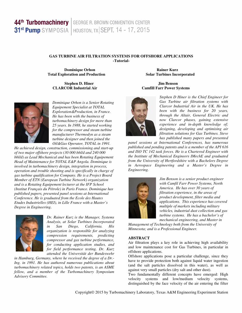
When gas turbines where first utilised on offshore platforms, they were most often installed with redundant capacity, it would be very common to have a group of 3 or more GT’s side by side, with 100% of the working load being fulfilled by only 2 of the units, keeping one of them as a redundant spare. This enabled maintenance to be carried out at any time without interruption to the operation and output of the platform. A number of trends have made this a much less common practice in recent times (Figure 21).
1. Gas turbines have become more reliable and able to run for longer periods of time before requiring shutdown for major maintenance, reducing the need for a spare.
2. The economics of running an oil and gas platform has changed such that there is an ever increasing demand to extract product from the ground at an increasing rate. This requires the use of every available resource, eliminating any spare or backup capacity / redundancy in the system.
3. Many new fields are now being exploited by floating-production-storage-offloading FPSO vessels, which can move from one field to the next as each one becomes exhausted. These vessels are super compact oil and gas platforms and as such cannot afford the space for redundant capacity.
With little spare GT capacity now available, it has become much more important to maximise gas turbine running time,
Copyright© 2015 by Turbomachinery Laboratory, Texas A&M Engineering Experiment Station
which has led to an increased focus on the reduction of compressor fouling and the use of longer life filters.
Figure 21 Offshore Platform and FPSO In addition, there is an increased use of latest technology gas turbines, which operate at higher firing temperatures with more exotic materials, making hot end corrosion more likely, while at the same time, there is a trend towards using higher sulphur fuels due to the location and nature of many of the new wells being exploited, which also tend to be located in drier, lower humidity climates. These changes have led to the need for a redesign of high velocity gas turbine inlet filtration systems, making them much more efficient with longer life, to address the weaknesses of the “Traditional” systems and tailor them to the different requirements demanded by the GT operators of today. ‘Modern’ high velocity air inlet systems
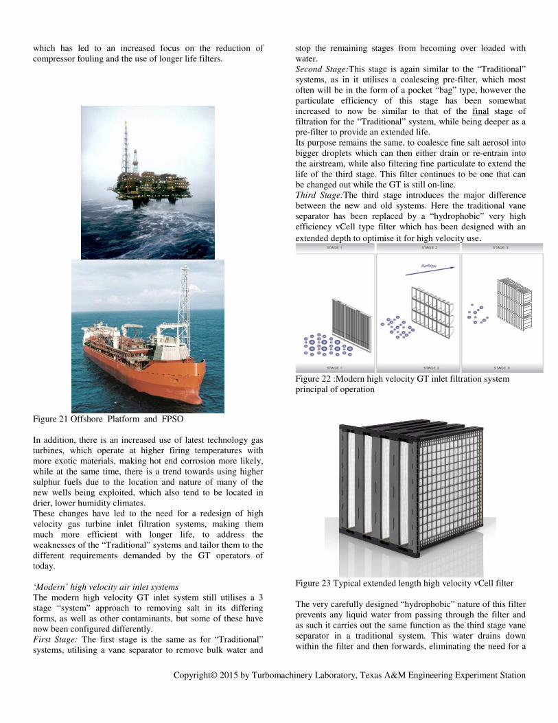
The modern high velocity GT inlet system still utilises a 3 stage “system” approach to removing salt in its differing forms, as well as other contaminants, but some of these have now been configured differently. First Stage: The first stage is the same as for “Traditional” systems, utilising a vane separator to remove bulk water and
stop the remaining stages from becoming over loaded with water. Second Stage:This stage is again similar to the “Traditional” systems, as in it utilises a coalescing pre-filter, which most often will be in the form of a pocket “bag” type, however the particulate efficiency of this stage has been somewhat increased to now be similar to that of the final stage of filtration for the “Traditional” system, while being deeper as a pre-filter to provide an extended life. Its purpose remains the same, to coalesce fine salt aerosol into bigger droplets which can then either drain or re-entrain into the airstream, while also filtering fine particulate to extend the life of the third stage. This filter continues to be one that can be changed out while the GT is still on-line. Third Stage:The third stage introduces the major difference between the new and old systems. Here the traditional vane separator has been replaced by a “hydrophobic” very high efficiency vCell type filter which has been designed with an
extended depth to optimise it for high velocity use.
Figure 22 :Modern high velocity GT inlet filtration system principal of operation
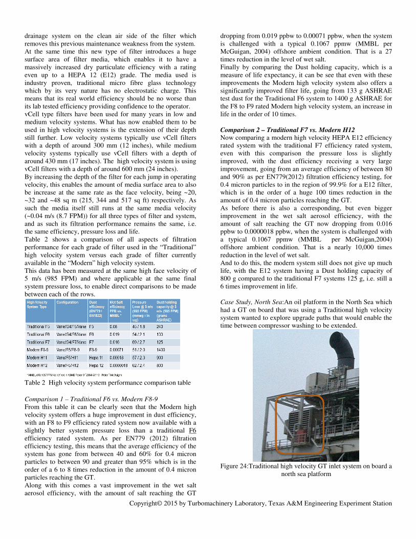
Figure 23 Typical extended length high velocity vCell filter The very carefully designed “hydrophobic” nature of this filter prevents any liquid water from passing through the filter and as such it carries out the same function as the third stage vane separator in a traditional system. This water drains down within the filter and then forwards, eliminating the need for a
Copyright© 2015 by Turbomachinery Laboratory, Texas A&M Engineering Experiment Station
drainage system on the clean air side of the filter which removes this previous maintenance weakness from the system. At the same time this new type of filter introduces a huge surface area of filter media, which enables it to have a massively increased dry particulate efficiency with a rating even up to a HEPA 12 (E12) grade. The media used is industry proven, traditional micro fibre glass technology which by its very nature has no electrostatic charge. This means that its real world efficiency should be no worse than its lab tested efficiency providing confidence to the operator. vCell type filters have been used for many years in low and medium velocity systems. What has now enabled them to be used in high velocity systems is the extension of their depth still further. Low velocity systems typically use vCell filters with a depth of around 300 mm (12 inches), while medium velocity systems typically use vCell filters with a depth of around 430 mm (17 inches). The high velocity system is using vCell filters with a depth of around 600 mm (24 inches). By increasing the depth of the filter for each jump in operating velocity, this enables the amount of media surface area to also be increase at the same rate as the face velocity, being ~20, ~32 and ~48 sq m (215, 344 and 517 sq ft) respectively. As such the media itself still runs at the same media velocity (~0.04 m/s (8.7 FPM)) for all three types of filter and system, and as such its filtration performance remains the same, i.e. the same efficiency, pressure loss and life. Table 2 shows a comparison of all aspects of filtration performance for each grade of filter used in the “Traditional” high velocity system versus each grade of filter currently available in the “Modern” high velocity system. This data has been measured at the same high face velocity of 5 m/s (985 FPM) and where applicable at the same final system pressure loss, to enable direct comparisons to be made between each of the rows.
Table 2 High velocity system performance comparison table
Comparison 1 – Traditional F6 vs. Modern F8-9
From this table it can be clearly seen that the Modern high velocity system offers a huge improvement in dust efficiency, with an F8 to F9 efficiency rated system now available with a slightly better system pressure loss than a traditional F6 efficiency rated system. As per EN779 (2012) filtration efficiency testing, this means that the average efficiency of the system has gone from between 40 and 60% for 0.4 micron particles to between 90 and greater than 95% which is in the order of a 6 to 8 times reduction in the amount of 0.4 micron particles reaching the GT. Along with this comes a vast improvement in the wet salt aerosol efficiency, with the amount of salt reaching the GT
dropping from 0.019 ppbw to 0.00071 ppbw, when the system is challenged with a typical 0.1067 ppmw (MMBL per McGuigan, 2004) offshore ambient condition. That is a 27 times reduction in the level of wet salt. Finally by comparing the Dust holding capacity, which is a measure of life expectancy, it can be see that even with these improvements the Modern high velocity system also offers a significantly improved filter life, going from 133 g ASHRAE test dust for the Traditional F6 system to 1400 g ASHRAE for the F8 to F9 rated Modern high velocity system, an increase in life in the order of 10 times. Comparison 2 – Traditional F7 vs. Modern H12
Now comparing a modern high velocity HEPA E12 efficiency rated system with the traditional F7 efficiency rated system, even with this comparison the pressure loss is slightly improved, with the dust efficiency receiving a very large improvement, going from an average efficiency of between 80 and 90% as per EN779(2012) filtration efficiency testing, for 0.4 micron particles to in the region of 99.9% for a E12 filter, which is in the order of a huge 100 times reduction in the amount of 0.4 micron particles reaching the GT. As before there is also a corresponding, but even bigger improvement in the wet salt aerosol efficiency, with the amount of salt reaching the GT now dropping from 0.016 ppbw to 0.0000018 ppbw, when the system is challenged with a typical 0.1067 ppmw (MMBL per McGuigan,2004) offshore ambient condition. That is a nearly 10,000 times reduction in the level of wet salt. And to do this, the modern system still does not give up much life, with the E12 system having a Dust holding capacity of 800 g compared to the traditional F7 systems 125 g, i.e. still a 6 times improvement in life.
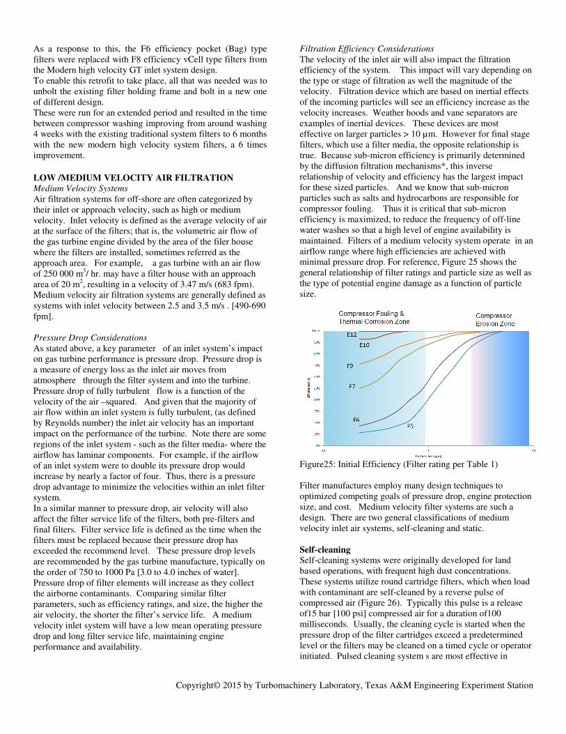
Case Study, North Sea:An oil platform in the North Sea which had a GT on board that was using a Traditional high velocity system wanted to explore upgrade paths that would enable the time between compressor washing to be extended.
Figure 24:Traditional high velocity GT inlet system on board a
north sea platform
Copyright© 2015 by Turbomachinery Laboratory, Texas A&M Engineering Experiment Station
As a response to this, the F6 efficiency pocket (Bag) type filters were replaced with F8 efficiency vCell type filters from the Modern high velocity GT inlet system design. To enable this retrofit to take place, all that was needed was to unbolt the existing filter holding frame and bolt in a new one of different design. These were run for an extended period and resulted in the time between compressor washing improving from around washing 4 weeks with the existing traditional system filters to 6 months with the new modern high velocity system filters, a 6 times improvement.
LOW /MEDIUM VELOCITY AIR FILTRATION Medium Velocity Systems
Air filtration systems for off-shore are often categorized by their inlet or approach velocity, such as high or medium velocity. Inlet velocity is defined as the average velocity of air at the surface of the filters; that is, the volumetric air flow of the gas turbine engine divided by the area of the filer house where the filters are installed, sometimes referred as the approach area. For example, a gas turbine with an air flow of 250 000 m3/ hr. may have a filter house with an approach area of 20 m2, resulting in a velocity of 3.47 m/s (683 fpm). Medium velocity air filtration systems are generally defined as systems with inlet velocity between 2.5 and 3.5 m/s . [490-690 fpm]. Pressure Drop Considerations
As stated above, a key parameter of an inlet system’s impact on gas turbine performance is pressure drop. Pressure drop is a measure of energy loss as the inlet air moves from atmosphere through the filter system and into the turbine. Pressure drop of fully turbulent flow is a function of the velocity of the air –squared. And given that the majority of air flow within an inlet system is fully turbulent, (as defined by Reynolds number) the inlet air velocity has an important impact on the performance of the turbine. Note there are some regions of the inlet system - such as the filter media- where the airflow has laminar components. For example, if the airflow of an inlet system were to double its pressure drop would increase by nearly a factor of four. Thus, there is a pressure drop advantage to minimize the velocities within an inlet filter system. In a similar manner to pressure drop, air velocity will also affect the filter service life of the filters, both pre-filters and final filters. Filter service life is defined as the time when the filters must be replaced because their pressure drop has exceeded the recommend level. These pressure drop levels are recommended by the gas turbine manufacture, typically on the order of 750 to 1000 Pa [3.0 to 4.0 inches of water]. Pressure drop of filter elements will increase as they collect the airborne contaminants. Comparing similar filter parameters, such as efficiency ratings, and size, the higher the air velocity, the shorter the filter’s service life. A medium velocity inlet system will have a low mean operating pressure drop and long filter service life, maintaining engine performance and availability.
Filtration Efficiency Considerations
The velocity of the inlet air will also impact the filtration efficiency of the system. This impact will vary depending on the type or stage of filtration as well the magnitude of the velocity. Filtration device which are based on inertial effects of the incoming particles will see an efficiency increase as the velocity increases. Weather hoods and vane separators are examples of inertial devices. These devices are most effective on larger particles > 10 µm. However for final stage filters, which use a filter media, the opposite relationship is true. Because sub-micron efficiency is primarily determined by the diffusion filtration mechanisms*, this inverse relationship of velocity and efficiency has the largest impact for these sized particles. And we know that sub-micron particles such as salts and hydrocarbons are responsible for compressor fouling. Thus it is critical that sub-micron efficiency is maximized, to reduce the frequency of off-line water washes so that a high level of engine availability is maintained. Filters of a medium velocity system operate in an airflow range where high efficiencies are achieved with minimal pressure drop. For reference, Figure 25 shows the general relationship of filter ratings and particle size as well as the type of potential engine damage as a function of particle size.
Figure25: Initial Efficiency (Filter rating per Table 1) Filter manufactures employ many design techniques to optimized competing goals of pressure drop, engine protection size, and cost. Medium velocity filter systems are such a design. There are two general classifications of medium velocity inlet air systems, self-cleaning and static. Self-cleaning
Self-cleaning systems were originally developed for land based operations, with frequent high dust concentrations. These systems utilize round cartridge filters, which when load with contaminant are self-cleaned by a reverse pulse of compressed air (Figure 26). Typically this pulse is a release of15 bar [100 psi] compressed air for a duration of100 milliseconds. Usually, the cleaning cycle is started when the pressure drop of the filter cartridges exceed a predetermined level or the filters may be cleaned on a timed cycle or operator initiated. Pulsed cleaning system s are most effective in
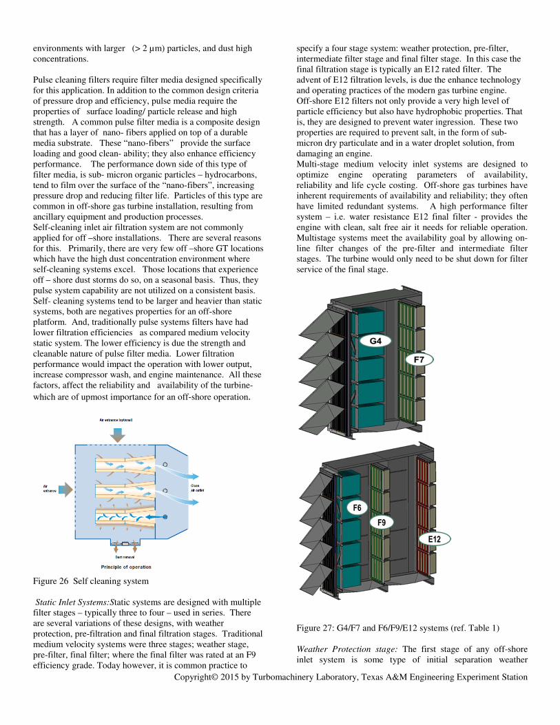
Copyright© 2015 by Turbomachinery Laboratory, Texas A&M Engineering Experiment Station
environments with larger (> 2 µm) particles, and dust high concentrations. Pulse cleaning filters require filter media designed specifically for this application. In addition to the common design criteria of pressure drop and efficiency, pulse media require the properties of surface loading/ particle release and high strength. A common pulse filter media is a composite design that has a layer of nano- fibers applied on top of a durable media substrate. These “nano-fibers” provide the surface loading and good clean- ability; they also enhance efficiency performance. The performance down side of this type of filter media, is sub- micron organic particles – hydrocarbons, tend to film over the surface of the “nano-fibers”, increasing pressure drop and reducing filter life. Particles of this type are common in off-shore gas turbine installation, resulting from ancillary equipment and production processes. Self-cleaning inlet air filtration system are not commonly applied for off –shore installations. There are several reasons for this. Primarily, there are very few off –shore GT locations which have the high dust concentration environment where self-cleaning systems excel. Those locations that experience off – shore dust storms do so, on a seasonal basis. Thus, they pulse system capability are not utilized on a consistent basis. Self- cleaning systems tend to be larger and heavier than static systems, both are negatives properties for an off-shore platform. And, traditionally pulse systems filters have had lower filtration efficiencies as compared medium velocity static system. The lower efficiency is due the strength and cleanable nature of pulse filter media. Lower filtration performance would impact the operation with lower output, increase compressor wash, and engine maintenance. All these factors, affect the reliability and availability of the turbine-
which are of upmost importance for an off-shore operation.
Figure 26 Self cleaning system
Static Inlet Systems:Static systems are designed with multiple filter stages – typically three to four – used in series. There are several variations of these designs, with weather protection, pre-filtration and final filtration stages. Traditional medium velocity systems were three stages; weather stage, pre-filter, final filter; where the final filter was rated at an F9 efficiency grade. Today however, it is common practice to
specify a four stage system: weather protection, pre-filter, intermediate filter stage and final filter stage. In this case the final filtration stage is typically an E12 rated filter. The advent of E12 filtration levels, is due the enhance technology and operating practices of the modern gas turbine engine. Off-shore E12 filters not only provide a very high level of particle efficiency but also have hydrophobic properties. That is, they are designed to prevent water ingression. These two properties are required to prevent salt, in the form of sub-micron dry particulate and in a water droplet solution, from damaging an engine. Multi-stage medium velocity inlet systems are designed to optimize engine operating parameters of availability, reliability and life cycle costing. Off-shore gas turbines have inherent requirements of availability and reliability; they often have limited redundant systems. A high performance filter system – i.e. water resistance E12 final filter - provides the engine with clean, salt free air it needs for reliable operation. Multistage systems meet the availability goal by allowing on-line filter changes of the pre-filter and intermediate filter stages. The turbine would only need to be shut down for filter service of the final stage.
Figure 27: G4/F7 and F6/F9/E12 systems (ref. Table 1) Weather Protection stage: The first stage of any off-shore inlet system is some type of initial separation weather

Copyright© 2015 by Turbomachinery Laboratory, Texas A&M Engineering Experiment Station
protection device, to minimize the amount of rain or sea spray entering the filter stages of the system. The two most common devices are weather hoods and weather vanes/ louvers. Both of these device function by changing the direction of the airflow, in such a manner that the rain drops, due to their size and mass, are separated from the inlet airflow. These devices are effective on droplets above 15 µm in size. Generally, the weather vane style will be more effective than weather hoods, but will have higher pressure drop. Pre-Filtration stage: There are two objectives of the pre –filter stage. First is to capture the larger size contaminant, by doing so this extends the filter life of the subsequent higher efficiency stages. Second, objective is to coalesce and separate any smaller water droplets that may have passed through the weather protection stage. For off-shore systems, any droplets will have a salt content, which as we know is detrimental to the turbine. By coalescing small droplets, this will reduce the amount of water removal that must be accomplished the subsequent stages. For off-shore applications, pre-filters are designed in bag/ pocket style geometry. This type of filter provides the best performance combination for water separation/coalescence and particle filtration. Pocket filters are available in several different filter efficiency grades G4 to F7 (per the EN 779, 2012 test standard) and design features. Selection of the pre-filter cannot be done without considering the full inlet system. The pre-filters need to work with the final stage(s) of filtration. For example, selecting a low grade pre-filter when the final filter is a high efficiency grade (E grades) will result in short filter life for the final filter and a higher average pressure drop for the system(Figure 27).
Figure 28: The pleated media is configured in panels in a “V” arrangement Intermediate and final filtration stage: A four stage inlet system will have an intermediate filter stage between the pre-filter and final filter. The objective of this filter is to provide
gradient efficiency levels; this approach yields the best compromise of filter life, pressure drop and efficiency. Efficiency ratings of intermediate filters are M6-F7 in accordance with the EN 779 (2012). A general design rule for multistage systems is that the efficiency ratings of each filter stage should not be greater than 3 grades. If the difference of efficiency ratings is too great, the final. filter stage will experience excessive contaminant load resulting in unacceptable service life.
Both intermediate and final filters are of similar design and construction. They differ only in their respective filter efficiency ratings. These filters typically use a pleated glass fiber media, or combination of glass and synthetic fibers, and occasionally membrane media. The pleated media is configured in panels in a “V” arrangement – this maximizes the amount filter media. The “V” configuration also minimizes air flow pressure loss through the filter (Figure 28). These filters are constructed with a durable plastic frames and headers. The filter media is sealed on all sides with a polyurethane material. Figure 28 is an example of this type of filter. Efficiency ratings range from F7 to E12 for this style of filter, where F7 would be used as an intermediate filter.
Table 3: Cost of compressor fouling.
Table 4: Typical LCC inputs: Sample LCC calculation for a large aeroderivative gas turbine. Life Cycle Cost: Life cycle analysis is a business tool to identify to the most cost effective option among of different alternative systems. Gas turbine filter system life cycle cost analysis (LCC) considers all related costs. These costs include the initial capital equipment cost of the inlet system and the operational cost. For off-shore system additional cost items must be consider, that is the value of the space the inlet system occupies on the platform, and its weight. Space on an off-

Copyright© 2015 by Turbomachinery Laboratory, Texas A&M Engineering Experiment Station
shore operation is very limited and thus very valuable. In the same manner, the weight of all systems is an important consideration. When a new off-shore platform is designed, it is common that an economic value – cost- is assigned for space and weight. For example, one operator of several off-shore systems estimates the value of platform space to be US$85,000/m2 . Operational cost includes maintenance cost related to the filter system and the cost related to turbine performance. Maintenance cost would include the cost to buy, ship and install, and dispose (used) filter elements. Note shipping filters to an off-shore location is a non-trivial cost, and adds to the value of filter system with longer service life. Turbine performance costs that are impacted by the filter system are the reduced power and increased heat rate due system pressure drop and compressor fouling. For example, the cost impact due to compressor fouling would be as outlined in Table 3. An example of LCC inputs is given in the Table 4.
ADDITIONAL CONSIDERATIONS ON OFFSHORE
AIR FILTRATION
Air Filter Arrangement Before the beginning of the 1990’s, air filtration was somewhat neglected in the attempt to minimize CAPEX. In a competitive, CAPEX driven purchasing process, the selection criteria may not provide the end user with the right product for their operation. Air filtration is a source of cost savings without impacting short term gas turbine behavior. In consequence, OEMs gain no advantage in offering the most effective filtration system above and beyond what is specified. In parallel, at the same period, air filter manufacturers saw that it was in their interest to educate their customers in order to install expensive products on customers’ plants. Extensive research , often based on field problems, led to a better understanding of the impact of poor air filtration on engine life, especially when sulfur is present in the fuel. Thus, the quality of the filter is highly dependent on the client understanding of their needs. The primary objective for customers becomes the capitalization of their own experience in order to improve their design requirements and subsequently their operation and the associated life cycle costs.
No Universal Solution
On offshore units, air quality is not the only criteria for designing gas turbine air filtration. An axial compressor of heavy duty gas turbines and industrial gas turbines is more sensitive to corrosion. This type of gas turbine requires a higher grade of air filtration. In parallel, H2S content in fuel gas or sulfur in liquid fuel also drives the design of the air filtration system. The existence of wind-blown dust adds a new parameter in the gas turbine air filtration as well. Consequently it seems difficult to find one single universal solution for all offshore environments.
Low/Medium Velocity
A low velocity air filtration system is based on a front speed of about 3 m/s or an air flow of about 3000 m3/h per filter element. A low velocity air filter offers the best grade of filtration for an air inlet gas turbine, like the E10 or the E12 according to EN 1822 (2009).
High Velocity
A high velocity air filtration system is based on a front speed of about 5 m/s or an air flow of about 6300 m3/h per filter element. High velocity filters are particularly appreciated offshore for their compactness. They offer two main advantages which are low weight and small footprint. A comparison between the high velocity technology and the low velocity technology displays the following data(Table 5):
High Velocity
Air Filter Low Velocity
Air Filter
Weight (kg) 10500 24500
Footprint (m2) 18,5 43
Width (mm) 4440 6500
Height (mm) 6150 8900
Depth (mm) 4170 6630
Table 5: Air Filter Weight and Dimensions for a 33000 kW Gas Turbine.
Gas turbine air filters are equipped with a transition piece which connects the filter to the duct. It is interesting to observe that this transition piece represents 70% of this additional weight for a low velocity filter. High velocity filter performance in current operation is F5 to F6 according to EN 779 (2012). Filter Lay-out
The filter lay-out, meaning the different stages which equip the air filtration is of prime importance. It is a multi-stage arrangement made of necessary functions (Table 6). Function Feature
Rainy Water Removal Weather Hood Vane Separator
Water Mist Removal Coalescor
Stand Still Water Removal Drainage
Removal of Accumulated Water in Filter Media
Vane Separator Filter Repellency
Sand Removal Inertial Feature Dust Filter
Big Particle Arrestance Pre-filter
Fine Particle Arrestance Fine Filter
Alkali Arrestance (Sulfur in Fuel)
Fine Filter
Table 6: Offshore Air filtration Functions. Therefore, it is important that the filter layout be able to answer the site challenges. A typical offshore air filtration lay-out is as follows(Table 7):
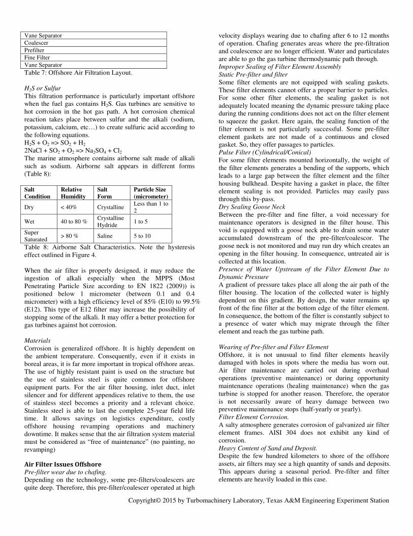
Copyright© 2015 by Turbomachinery Laboratory, Texas A&M Engineering Experiment Station
Vane Separator
Coalescer
Prefilter
Fine Filter
Vane Separator
Table 7: Offshore Air Filtration Layout. H2S or Sulfur
This filtration performance is particularly important offshore when the fuel gas contains H2S. Gas turbines are sensitive to hot corrosion in the hot gas path. A hot corrosion chemical reaction takes place between sulfur and the alkali (sodium, potassium, calcium, etc…) to create sulfuric acid according to the following equations. H2S + O2 => SO2 + H2 2NaCl + SO2 + O2 => Na2SO4 + Cl2 The marine atmosphere contains airborne salt made of alkali such as sodium. Airborne salt appears in different forms (Table 8): Salt
Condition
Relative
Humidity
Salt
Form
Particle Size
(micrometer)
Dry < 40% Crystalline Less than 1 to 2
Wet 40 to 80 % Crystalline Hydride
1 to 5
Super Saturated
> 80 % Saline 5 to 10
Table 8: Airborne Salt Characteristics. Note the hysteresis effect outlined in Figure 4. When the air filter is properly designed, it may reduce the ingestion of alkali especially when the MPPS (Most Penetrating Particle Size according to EN 1822 (2009)) is positioned below 1 micrometer (between 0.1 and 0.4 micrometer) with a high efficiency level of 85% (E10) to 99.5% (E12). This type of E12 filter may increase the possibility of stopping some of the alkali. It may offer a better protection for gas turbines against hot corrosion. Materials
Corrosion is generalized offshore. It is highly dependent on the ambient temperature. Consequently, even if it exists in boreal areas, it is far more important in tropical offshore areas. The use of highly resistant paint is used on the structure but the use of stainless steel is quite common for offshore equipment parts. For the air filter housing, inlet duct, inlet silencer and for different appendices relative to them, the use of stainless steel becomes a priority and a relevant choice. Stainless steel is able to last the complete 25-year field life time. It allows savings on logistics expenditure, costly offshore housing revamping operations and machinery downtime. It makes sense that the air filtration system material must be considered as “free of maintenance” (no painting, no revamping)
Air Filter Issues Offshore Pre-filter wear due to chafing.
Depending on the technology, some pre-filters/coalescers are quite deep. Therefore, this pre-filter/coalescer operated at high
velocity displays wearing due to chafing after 6 to 12 months of operation. Chafing generates areas where the pre-filtration and coalescence are no longer efficient. Water and particulates are able to go the gas turbine thermodynamic path through. Improper Sealing of Filter Element Assembly
Static Pre-filter and filter
Some filter elements are not equipped with sealing gaskets. These filter elements cannot offer a proper barrier to particles. For some other filter elements, the sealing gasket is not adequately located meaning the dynamic pressure taking place during the running conditions does not act on the filter element to squeeze the gasket. Here again, the sealing function of the filter element is not particularly successful. Some pre-filter element gaskets are not made of a continuous and closed gasket. So, they offer passages to particles. Pulse Filter (Cylindrical/Conical)
For some filter elements mounted horizontally, the weight of the filter elements generates a bending of the supports, which leads to a large gap between the filter element and the filter housing bulkhead. Despite having a gasket in place, the filter element sealing is not provided. Particles may easily pass through this by-pass. Dry Sealing Goose Neck
Between the pre-filter and fine filter, a void necessary for maintenance operators is designed in the filter house. This void is equipped with a goose neck able to drain some water accumulated downstream of the pre-filter/coalescor. The goose neck is not monitored and may run dry which creates an opening in the filter housing. In consequence, untreated air is collected at this location. Presence of Water Upstream of the Filter Element Due to
Dynamic Pressure
A gradient of pressure takes place all along the air path of the filter housing. The location of the collected water is highly dependent on this gradient. By design, the water remains up front of the fine filter at the bottom edge of the filter element. In consequence, the bottom of the filter is constantly subject to a presence of water which may migrate through the filter element and reach the gas turbine path. Wearing of Pre-filter and Filter Element
Offshore, it is not unusual to find filter elements heavily damaged with holes in spots where the media has worn out. Air filter maintenance are carried out during overhaul operations (preventive maintenance) or during opportunity maintenance operations (healing maintenance) when the gas turbine is stopped for another reason. Therefore, the operator is not necessarily aware of heavy damage between two preventive maintenance stops (half-yearly or yearly). Filter Element Corrosion.
A salty atmosphere generates corrosion of galvanized air filter element frames. AISI 304 does not exhibit any kind of corrosion. Heavy Content of Sand and Deposit.
Despite the few hundred kilometers to shore of the offshore assets, air filters may see a high quantity of sands and deposits. This appears during a seasonal period. Pre-filter and filter elements are heavily loaded in this case.

Copyright© 2015 by Turbomachinery Laboratory, Texas A&M Engineering Experiment Station
Improper Filter Media
Cellulose or cellulose blends do not behave properly due to the high humidity of the offshore conditions.
Offshore Operational Feedback F5/F6 Air Filter
The F5 or F6 filtration levels according to the EN 779 standard (2012) do not protect the axial compressor adequately. Fine dust and particles are able to reach the compressor. Due to a 24/7 operation, large quantities are ingested by the gas turbine. This generates compressor fouling. A higher filtration level is envisaged offshore and the reasons for this choice are developed later in this paper. High Filter Pressure Losses
High pressure losses are very seldom recorded on gas turbine filters offshore. It is difficult today to provide a clear explanation for this. Pulse Jet Technology
Pulse jet technology is not adequate offshore. The first reason is that the ambient air is not heavily loaded with particles exception to seasonal condition of wind-blown dust in some areas (the Guinea Gulf). This means that usually the quantities to pulse are very small. The second reason is that the air is saturated by water which makes the accumulated oily dust sticky. In consequence, this means that the pulse system is only partially efficient. Cellulosic Filter Media
Cellulosic or blend cellulosic filter media are humidity sensitive. Synthetic media are preferred offshore. Mind Set
Operational crews do not necessarily establish a close link between gas turbine air filtration quality and long term operation damage.
INTEREST IN HIGH PERFORMANCE FILTRATION
Improve Availability. The use of a high efficiency filter is particularly interesting for offshore assets. It may significantly improve key factors relative to the oil or gas production. One of these key factors is the gas turbine component availability. Compressor
The high efficiency filter improves the integrity of the compressor. In fact, it avoids compressor fouling and it reduces the fine dust quantities passing through the compressor. At the very least, it postpones the fouling occurrence. Avoiding this fouling reduces the compressor surge occurrence which may impede compressor integrity. In the same way, it keeps the different compressor paths used for the engine air secondary flows clear and clean. Keeping the axial compressor clean reduces the deterioration of the compressor polytropic head which impacts the compressor thrust load. The engine thrust load is maintained longer as per design, extending the life of thrust components. Improving the integrity of the compressor section reduces the occurrence of domestic object damage or an unplanned event stopping the gas turbine.
Off-line washing
The main advantage of removing dust, salt and all type of particles is to save the off-line water wash operation which is not appreciated on an offshore plant. The off-line water wash is always a requirement from maintenance organization which undoubtedly impacts the oil and gas production. This operation turns off the gas turbine for hours or days, depending on the type of gas turbine technology we are looking at. This operation can be repeated from two to four times a year, never more. Saving one day means saving 0.3% availability. Hot Path
The high efficiency filter allows clean secondary air flows to be sent to blades, nozzles, disks and bearing sealing cavities. This cleanliness keeps the secondary flow functions nominal to design. It means that extending the nominal cooling for the hot gas path improves the durability of the different parts subject to creep. Example of Filter Retrofitting
In the Persian Gulf, an air filter retrofit was carried out on a 13-MW gas turbine. The initial air filtration system was made up of a high velocity multistage filter. The filter grade was F6. After 4000 hours of operation the axial compressor was particularly dirty. Salt, dust and carbon black were the deposits on the blade suction and pressure faces as shown on the compressor rotor hereafter (Figure 29).
Figure 29: Axial Compressor after 4000 Running Hours with F6 Air Filtration. A new housing was loaded on to the offshore platform from a crane barge. This new filter housing accommodates a low velocity air filtration based on an E12 grade according EN 1822. The gas turbine was dismantled after 5300 running hours. The axial compressor was found clean, like new (Figure 30).

Copyright© 2015 by Turbomachinery Laboratory, Texas A&M Engineering Experiment Station
Figure 30: Same Axial Compressor after 5300 Running Hours with E12 Air Filtration.
Reduction of OPEX Using a high efficiency air filter offshore may reduce the OPEX and may provide associated benefits. The frequency of scheduled maintenance operations such as off-line washing can be reduced. The scheduled maintenance such as combustor changes, hot section exchanges, overhauls may be postponed for hundreds or thousands of hours. But the main cost savings come from the reduction of the occurrence of unplanned events. This reduction in maintenance operations may offer savings both on crew mobilization and on associated logistics (helicopter, supply boat, accommodation). In addition, it would offer the possibility to use the POB (Personnel On Board) capability of the offshore plant for other operations if needed. In the same way, it would offer substantial savings on parts and associated freight costs to carry these goods to site in remote location like the Guinea Gulf, the North Sea, etc…Consequently, it may also simplify the management of the gas turbine maintenance schedule.
Improve thermal efficiency and power output With gas turbine ageing, fouling may generate 10% or more power losses and may slightly increase the gas turbine heat rate by few percent. This fact is detrimental to production especially for gas processing and water processing. For these two process functions, it is always beneficial to operate at the highest capacity. Maintaining power means we can to deliver more gas or inject more water acting directly on the oil and gas production performances. Maintaining thermal efficiency means we can operate the gas turbines in a greener way whatever the functions (power generation or mechanical drive) and it means we can call for more gas (for gas plants) by reducing the use of fuel gas quantities. In addition, all the losses coming from fouling are non recoverable with an on-line or off-line water wash. Running highly probable scenarios for 25 000 gas turbine running hours by comparing the two types of filtration (Low Efficiency typically F6 according to EN 779(2012) and High Efficiency typically E10 according to EN 1822,2009), it is possible to obtain a gain in power of up to 3% all along the running operation with the following hypothesis (Figure 31, 32):
• Off-line washing every 4380 running hours for Low Efficiency Filtration and every 8760 running hours for High Efficiency Filtration.
• 1% non recoverable power after washing.
• Additional 10 Pa pressure losses for new High Efficiency Filter and additional 250 Pa pressure losses before exchange.
• High Efficiency Filter change every 8760 running hours.
The balance in power is positive when using high efficiency filtration.
Figure 31: Low Efficiency and High Efficiency Filter
Comparison.
In this particular case the balance of power is positive by 1.5% (Figure 32):
Figure 32: Gain in Power with Fouling Hypothesis.
In consequence, the installation of a high efficiency filtration system provides more gain in power despite the additional gas turbine inlet losses than minimizing gas turbine inlet pressure losses with a low efficiency filtration system which creates more loss in power due to compressor fouling.
OUTLOOK AND CONCLUSIONS
In this tutorial, we have outlined the importance of inlet air filtration, in particular in challenging environments such as offshore.

Copyright© 2015 by Turbomachinery Laboratory, Texas A&M Engineering Experiment Station
In offshore, marine and coastal environments, the gas turbine has to be protected from salt ingress, and, depending on the specific situation , from dust and other contaminants. Depending on specific environmental situations, as well as economic and logistic considerations, we have outlined solution involving high and low/medium velocity air filtration solutions, that are both in use in many installations. There are some open questions, however, where from an oil and gas operation perspective, the gas turbine air filtration needs additional research and development in different domains (salts, water, repellency, velocity concept) that may improve offshore operations dramatically. All these issues evolve around the ingestion of salts into the gas turbine. Any improvement in alkali filtration would help to burn sour gas in gas turbines. The advantage relative to gas treatment is very significant because it may avoid the installation of H2S fuel gas treatment units which are large in footprint, heavy in weight and very power demanding. Oil and gas operators are awaiting new developments. -Testing: The performance of the air filtration system towards salts (crystalline or crystalline hydride) has not been widely investigated. There is, however a Test Specification available (Wilcox et al, 2011). -Water :Water can transport salt into the engine. Tests have to be agreed upon to determine the system performance regarding water ingress. Water can be present either from the inlet air, or can form within the system when the relative humidity is high. A GMRC standard exists (Wilcox et al,2011) to test for the capability of inlet systems to keep water from entering the engine. Detailed questions involve issues like the durability of filtration materials that don’t allow water to pass through. -Performance for small particles: A high velocity air filter is a useful concept offshore because it exhibits weight and footprint savings. For the future, the operators have clearly identified the advantages using high efficiency filters. Thus a high velocity system with high efficiency air filtration would be desirable.
REFERENCES
Aldi, N., Morini, M., Pinelli, M., Spina, P. R., Suman, A., Venturini, M., 2014, “Performance Evaluation of Non-Uniformly Fouled Axial Compressor Stages by Means of Computational Fluid Dynamics Analyses”, Journal of
Turbomachinery, 136, pp. 021016 (11 pages) ASHRAE Standard 52.2,2007, Method of Testing General Ventilation Air-Cleaning Devices for Removal Efficiency by Particle Size Brekke, O., Bakken, L. E., and Syverud, E., 2009, “Filtration of Gas Turbine Intake Air in Offshore Installations: The Gap Between Test Standards and Actual Operating Conditions”, ASME Paper No. GT2009-59202.
Brun,K., Kurz,R.,2010, ‘Myth : All Corrosion is the Same’, Turbomachinery International, Feb.2010. EN 779 Particulate Air Filters for General Ventilation – Determination of the Filtration Performance. EN 1822-1 High Efficiency Air Filters (EPA, HEPA and UPLA) – Part 1: Classification, Performance, Testing and Marking. Frith,P.C.,1992, ‘The Effect of Compressor Rotor Tip Crops on Turboshaft Engine Performance’,ASME Paper 92-GT-83. Gas Turbine Inlet Design Handbook, Department of the Navy, Naval Sea Systems Engineering Station, Philadelpia, Pa, 1983. ISO 8217 Petroleum Products - Fuels (class F) – Specification of Marine Fuels.
Kappis, W., 2012, “Detailed Compressor Degradation Effect Modeling for Single Blade Rows while Assessing its Local and Overall Consequences,” ASME Paper GT2012-68475.
Kappis, W., 2013, “Impact of Degradation on the Operational Behavior of a Stationary Gas Turbine and in Detail on the Associated Compressor,” Proceedings of the 2nd Middle East Turbomachinery Symposium, Doha, Qatar. Kurz, R., Meher-Homji,C., Brun,K., Moore, J., 2013, Gas Turbine Performance and Maintenance, 42nd Turbosymposium, Houston,Tx. Kurz, R., Brun, K., 2001, “Degradation in Gas Turbine Systems” , Journal of Engineering for Gas Turbines and
Power, 123, pp.70-77. Kurz, R., Brun, K., Wollie,M. 2009, “Degradation Effects on Industrial Gas Turbines”, Journal of Engineering for Gas
Turbines and Power, 131, p. 062401 (12 pages) Kurz, R., Brun, K., 2012, “Fouling Mechanism in Axial Compressors”, Journal of Engineering for Gas Turbines and
Power, 134, p. 032401 (12 pages) McGuigan,P.T.,2004 ,’Salt in the Marine Environmen and the creation of a standard input for gas turbine air intake filtration systems , ASME Paper GT2004-53113 Meher-Homji, C. B., Chaker, M., Bromley, A. F., 2009, “The Fouling of Axial Flow Compressors- Causes, Effects, Susceptibility and Sensitivity” ASME Paper No: GT2009-59239. Morini, M., Pinelli, M., Spina, P. R., Venturini, M., 2011, “Numerical Analysis of the Effects of Non-Uniform Surface Roughness on Compressor Stage Performance”, Journal of
Engineering for Gas Turbines and Power, 133(7), 072402 (8 pages)

Copyright© 2015 by Turbomachinery Laboratory, Texas A&M Engineering Experiment Station
Parker, G. J., Lee, P., 1972, “Studies of the Deposition of Sub-Micron Particles on Turbine Blades”, Proceedings of the
Institution of Mechanical Engineers, 186(1), pp. 519-526 Stalder,J.P., Sire,J., 2001, Salt percolation through gas turbine air filtration systems and its contribution to tatal contaminant level, IJPGC 2001, New Orleans,LA,USA. Suman, A., Morini, M., Kurz, R., Aldi, N., Brun, K., Pinelli, M., Spina, P. R., 2014a, “Quantitative CFD Analyses of Particle Deposition on a Transonic Axial Compressor Blade, Part II: Impact Kinematics and Particle Sticking Analysis”, Journal of Turbomachinery, 137(2), p. 021009 Suman, A., Kurz, R., Aldi, N., Morini, M., Brun, K., Pinelli, M., Spina, P. R., 2014b, “Quantitative CFD Analyses of Particle Deposition on a Transonic Axial Compressor Blade, Part I: Particle Zones Impact”, Journal of Turbomachinery, 137(2), p. 021010 Vigueras Zuniga, M. O., 2007, “Analysis of Gas Turbine Compressor Fouling and Washing on Line”, Ph. D. Thesis,
Cranfield University, UK
Vigeland, Ø., 2005, “Inlet Filter Impact on Gas Turbine Performance Deterioration,” Master’s Thesis, NTNU, Trondheim, Norway. Wilcox,M.A., Poerner,N.W., 2011, Gas Turbine Filter Efficiency Test Procedure: Liquid and Solid Particles, GMRC, Dallas,Tx. Wilcox, M., Baldwin, R., Garcia-Hernandez, A., Brun, K., 2010, “Guideline for gas turbine inlet air filtration systems”, Release 1.0,GMRC, Dallas,Tx