
Tutorial: SIMS Basics - University of...
40
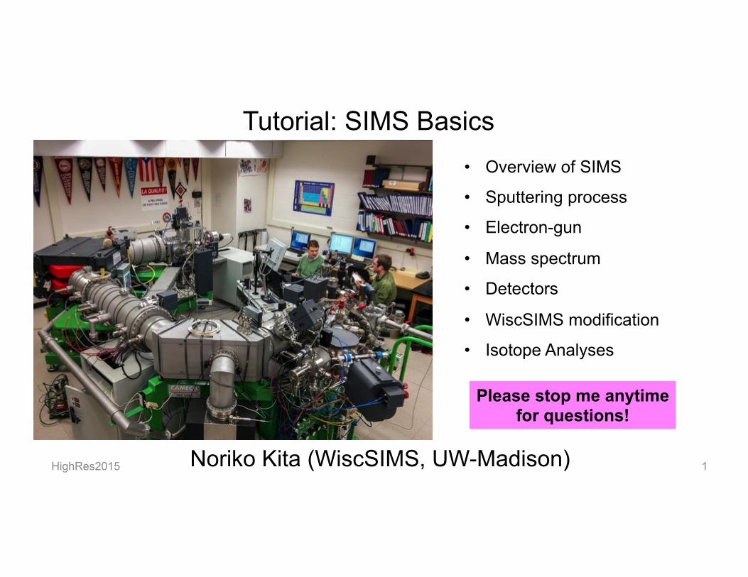
Tutorial: SIMS Basics Noriko Kita (WiscSIMS, UW-Madison) HighRes2015 1 • Overview of SIMS • Sputtering process • Electron-gun • Mass spectrum • Detectors • WiscSIMS modification • Isotope Analyses Please stop me anytime for questions!
Transcript of Tutorial: SIMS Basics - University of...
Tutorial: SIMS Basics
Noriko Kita (WiscSIMS, UW-Madison) HighRes2015 1
• Overview of SIMS
• Sputtering process
• Electron-gun
• Mass spectrum
• Detectors
• WiscSIMS modification
• Isotope Analyses
Please stop me anytime for questions!
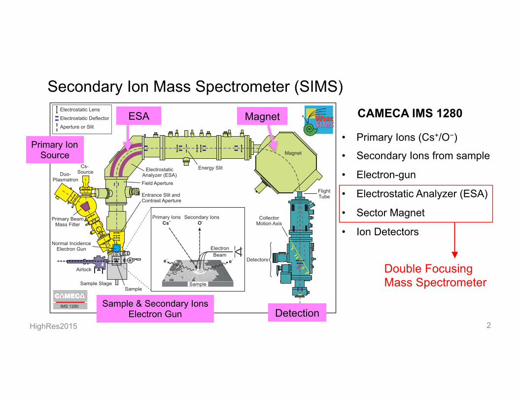
Secondary Ion Mass Spectrometer (SIMS)
HighRes2015 2
IMS 1280
Secondary Ions
Electron
Beam ?e?e
Primary Ions+Cs
Sample
?O
Electrostatic Lens
Electrostatic Deflector
Aperture or Slit
Collector
Motion Axis
Flight
Tube
Energy Slit
Primary Beam
Mass Filter
Field Aperture
Entrance Slit and
Contrast Aperture
Normal Incidence
Electron Gun
Airlock
Sample Stage
Sample
Duo-
Plasmatron
Cs-
Source
Detectors
Magnet
Electrostatic
Analyzer (ESA)
Sample & Secondary Ions Electron Gun Detection
Primary Ion Source
ESA Magnet CAMECA IMS 1280
• Primary Ions (Cs+/O−)
• Secondary Ions from sample
• Electron-gun
• Electrostatic Analyzer (ESA)
• Sector Magnet
• Ion Detectors
Double Focusing Mass Spectrometer

Secondary Ion Mass Spectrometer (SIMS)
HighRes2015 3
Double Focusing Mass Spectrometers
§ Large radius (high mass resolution: M/ΔM ≥ 5,000)
Ø IMS1270/1280/1280HR: Stable isotope, Geochronology, Nuclear forensic
Ø SHRIMP: Geochronology (zircon U-Pb ages)
Ø NanoSIMS: High spatial resolution (50nm beam) Imaging, biological applications
§ Conventional SIMS (low mass resolution): IMF 7f/ 7fGeo:
TOF (Time of flight): Shallow depth analysis, thin film
--------------------------- R = 585 mm
----------------- R = 1,000 mm
------- R = 120 mm
Sector Magnet radius

Secondary Ion Mass Spectrometer (SIMS)
HighRes2015 4
Analytical volume 2µm - 10µm diameter ~1µm depth à 0.3 ng to a few pg
Surface analysis - trace element - elemental mapping - isotope ratios
Secondary ions are produced by the sputtering of primary ions
±10kV
Secondary Ion
Primary Ion (+10kV/−13kV)
Magnetic Field Electrostatic Field
Double focusing Mass Spectrometer
18O 16O
Ion counters Sample
E-gun
Simplified Schematic of SIMS
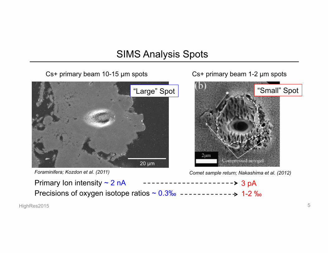
SIMS Analysis Spots
HighRes2015 5
selected [Bralower et al., 1995; Kelly et al., 1998; Tripatiet al., 2003]. The calcareous nannofossil biozonation con-structed for this section indicates that the stratigraphyextends relatively uninterrupted from the late Paleocenethrough the early Eocene (zones NP9 to NP14a) [Bralower and
Mutterlose, 1995]. Accordingly, the age model employedin this study was constructed using the published nanno-fossil biostratigraphy [Bralower and Mutterlose, 1995] andthe ages assigned to the datums upon which this biozona-tion is based [Berggren et al., 1995]. Thus, age estimates
Table 1. Sample Core Depths, Assigned Calcareous Nannofossil Zones, and Estimated Agesa
Datumb Biozone Sample ID Age (Ma)
SedimentationRate, Linear(m/Myr)
Depth,865B (mbsf)
Depth,865C (mbsf)
FO D. sublodoensis NP14 865B 9H‐4 10 49.70 2.67 79.60LO D. orthostylus NP13 865B 9H‐6 70 50.60 4.00 83.20FO D. lodoensis NP12 865B 10H‐4 60 52.85 2.84 89.60FO T. contortus NP11 865B 10H‐5 111/865C
11H‐2 13453.61 2.64/5.6 91.61 91.74
FO D. diastypus NP10 865B 11H‐6 70/865C12H‐3 138
55.00 7.62/7.94 102.20 102.68
FO D. multiradiatus NP9 865C 13H‐5 80 56.20 9.93 114.60
aCore depths [Bralower and Mutterlose, 1995] and ages [Berggren et al., 1995] assigned to various nannofossil biostratigraphic datums for calculatinglinear sedimentation rates that were used to construct a chronostratigraphic framework for the late Paleocene–early Eocene section from Site 865.
bFO, first occurrence; LO, last occurrence.
Figure 1. (a) Scanning electron microscope (SEM) image of a test of Morozovella velascoensis (ODPSite 865) in edge view. (b) Enlargement of the chamber wall and muricae. Several mural pores are high-lighted by arrows. Blade‐shaped diagenetic crystallites are cemented on top of the biogenic muricae.(c, d) High contrast SEM backscattered electron images of a polished morozovellid test. Figure 1c is across section taken perpendicular to the coiling axis of a M. velascoensis test from the 300–355 mm sievefraction, with a width of 450 mm (Hole 865C, 103.10 mbsf). Figure 1d is an enlargement of a cross sectionof the same test, showing muricae fused into a keel‐like structure at the test periphery. (e) SEM image ofthe gold‐coated sample displaying a ∼10 mm ion microprobe pit for d18O analysis. Textures in the pit areetched by the Cs+ beam.
KOZDON ET AL.: d18O IN MURICAE BASES BY ION MICROPROBE PA3206PA3206
3 of 17
Cs+ primary beam 10-15 µm spots
Comet sample return; Nakashima et al. (2012)
Cs+ primary beam 1-2 µm spots
Foraminifera; Kozdon et al. (2011)
Primary Ion intensity ~ 2 nA Precisions of oxygen isotope ratios ~ 0.3‰
3 pA 1-2 ‰
“Large” Spot “Small” Spot

Most of elements in periodic table are ionized
HighRes2015 6 Modified from Evans Analytical Group: http://www.eaglabs.com/mc/sims-theory.html
Cs+/Sec(−) O−/Sec(+)
- Noble gases do not ionize. - Nitrogen in carbon bearing phase: CN−
Ionization efficiency varies significantly from 0.1 to 10%
Secondary Ions
±10kV
Primary Ions Cs: +10kV O−: −13kV
Sample Higher electro-negativity: O−, C−, S−, Si−
Higher ionization tendency: Mg+, Ca+, Pb+

Secondary Ions: Ionization Efficiency
HighRes2015 7
Ionization efficiencies = (N of secondary ions)/ (N of atoms sputtered)
O− in silicate, carbonates, oxide minerals ~10%
C− in carbonates ≤ 0.3%
Si− in quartz ~ 1%
Secondary Ion intensities Calcite (CaCO3) C− = 2×10⁷ cps O− = 2×10⁹ cps Ca− ~0 (ionized as CaO−) Quartz (SiO2) O− = 2×10⁹ cps Si− = 1×10⁸ cps
Instrumental bias on isotope ratio = (18O−/16O−)SIMS /(18O/16O)True
oxygen isotope (18O/16O) in silicate, carbonates, oxide minerals: ±10‰
carbon isotope (13C/12C) in calcite: −40‰
silicon isotope (30Si/28Si) in quartz: −30‰

Sputtering of samples
HighRes2015 8 IMS 1280
Secondary Ions
Electron
Beam ?e?e
Primary Ions+Cs
Sample
?O
Electrostatic Lens
Electrostatic Deflector
Aperture or Slit
Collector
Motion Axis
Flight
Tube
Energy Slit
Primary Beam
Mass Filter
Field Aperture
Entrance Slit and
Contrast Aperture
Normal Incidence
Electron Gun
Airlock
Sample Stage
Sample
Duo-
Plasmatron
Cs-
Source
Detectors
Magnet
Electrostatic
Analyzer (ESA)
−10kV
Cs+ +10kV
+10kV
O− −13kV
Ion Sources
Sample
Impact Energy 20-23 keV
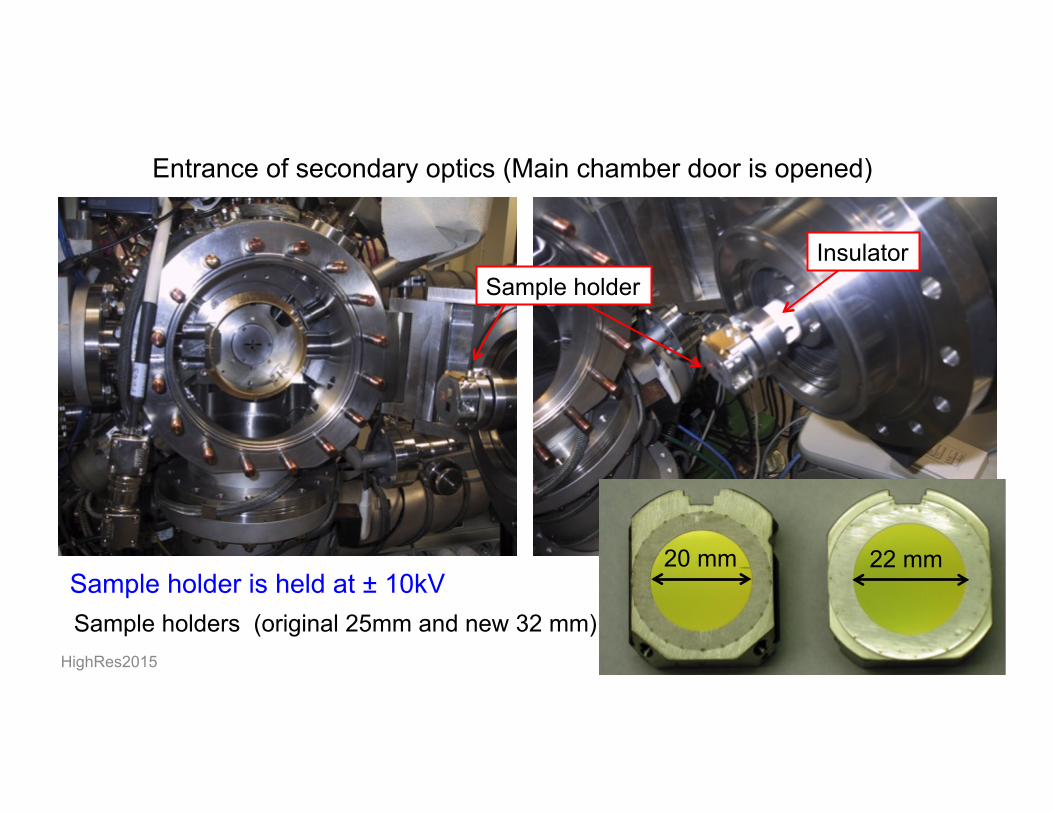
Entrance of secondary optics (Main chamber door is opened)
HighRes2015 9
Sample holder Insulator
Sample holder is held at ± 10kV Sample holders (original 25mm and new 32 mm)
20 mm 22 mm

Sputtering Process
HighRes2015 10
Ejection of electron from sample surface causes charging of sample --- electron gun
Initial kinetic energy of secondary ions
--- double focusing mass spectrometer Formation of multiple atomic and molecular ions, divalent ions
--- high mass resolution power by large radius sector magnet
These factors determined the performance of the instrument for high precision stable isotope analyses

Primary ion implantation and ejection of atoms from interior
HighRes2015 11
IMS 1280
Secondary Ions
Electron
Beam ?e?e
Primary Ions+Cs
Sample
?O
Electrostatic Lens
Electrostatic Deflector
Aperture or Slit
Collector
Motion Axis
Flight
Tube
Energy Slit
Primary Beam
Mass Filter
Field Aperture
Entrance Slit and
Contrast Aperture
Normal Incidence
Electron Gun
Airlock
Sample Stage
Sample
Duo-
Plasmatron
Cs-
Source
Detectors
Magnet
Electrostatic
Analyzer (ESA)
- Primary ions are implanted to the interior of sample.
- Atoms in the sample are displaced by collision cascade.
Primary Ion 133Cs+ Impact energy 20 keV
Lattice structure is destroyed: amorphous layer (~30nm)
0V
-10kV
Some atoms are ejected from surface
“Sputtering"
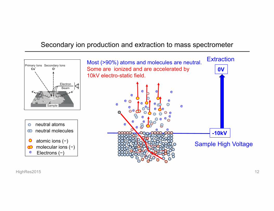
Secondary ion production and extraction to mass spectrometer
HighRes2015 12
IMS 1280
Secondary Ions
Electron
Beam ?e?e
Primary Ions+Cs
Sample
?O
Electrostatic Lens
Electrostatic Deflector
Aperture or Slit
Collector
Motion Axis
Flight
Tube
Energy Slit
Primary Beam
Mass Filter
Field Aperture
Entrance Slit and
Contrast Aperture
Normal Incidence
Electron Gun
Airlock
Sample Stage
Sample
Duo-
Plasmatron
Cs-
Source
Detectors
Magnet
Electrostatic
Analyzer (ESA)
0V
-10kV
Extraction
Sample High Voltage
Most (>90%) atoms and molecules are neutral. Some are ionized and are accelerated by 10kV electro-static field.
e
e e
e
e e e e
e
e
e
e e e
e
e
e
e e
e e
e e
e e
e
atomic ions (−)
neutral atoms
molecular ions (−)
neutral molecules
Electrons (−) e
Secondary ion production and extraction to mass spectrometer
HighRes2015 13
IMS 1280
Secondary Ions
Electron
Beam ?e?e
Primary Ions+Cs
Sample
?O
Electrostatic Lens
Electrostatic Deflector
Aperture or Slit
Collector
Motion Axis
Flight
Tube
Energy Slit
Primary Beam
Mass Filter
Field Aperture
Entrance Slit and
Contrast Aperture
Normal Incidence
Electron Gun
Airlock
Sample Stage
Sample
Duo-
Plasmatron
Cs-
Source
Detectors
Magnet
Electrostatic
Analyzer (ESA)
0V
-10kV atomic ions (−)
neutral atoms
molecular ions (−)
neutral molecules
Electrons (−) e
Extraction
Sample High Voltage
e
e e
e
e e e e
e
e
e
e e e
e
e
e
e e
e e
e e
e e
e
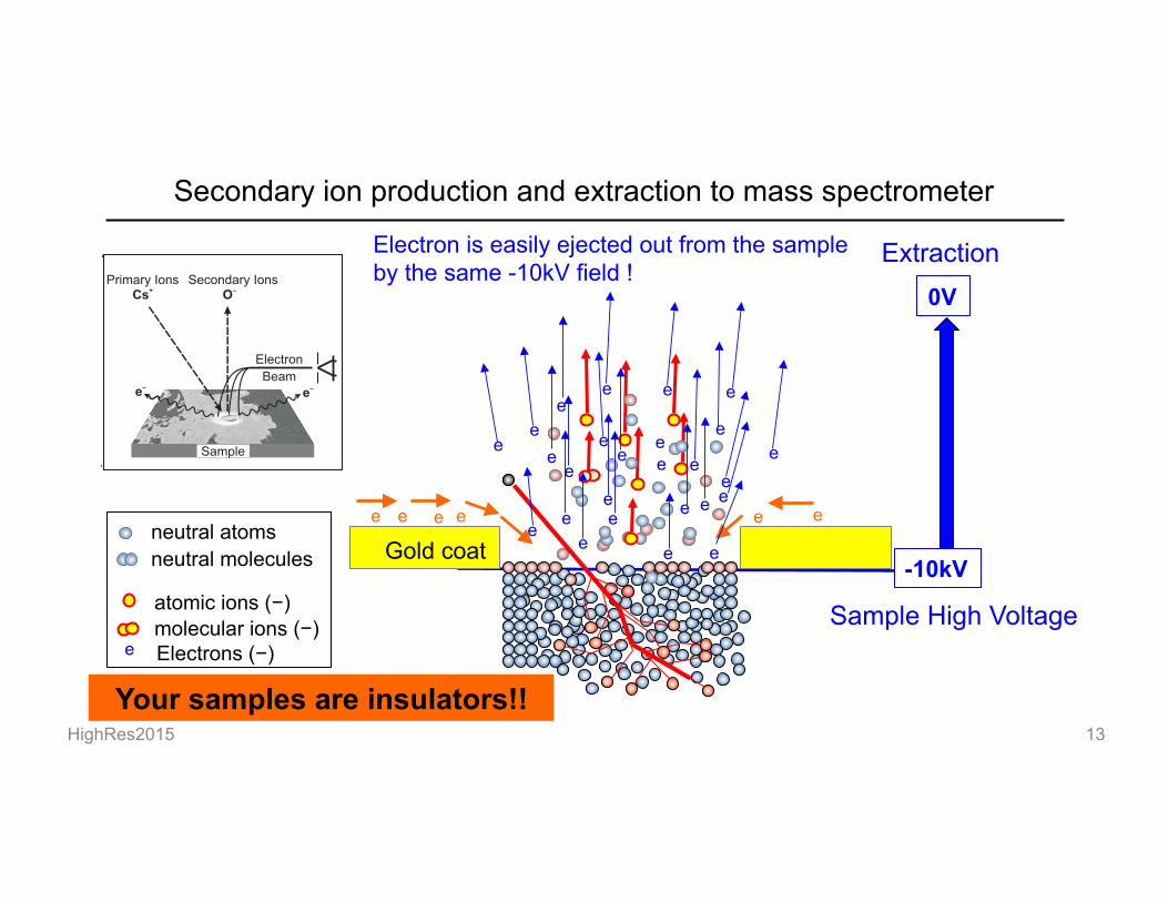
Gold coat e e e e e e
Electron is easily ejected out from the sample by the same -10kV field !
Your samples are insulators!!
Secondary ion production and extraction to mass spectrometer
HighRes2015 14
IMS 1280
Secondary Ions
Electron
Beam ?e?e
Primary Ions+Cs
Sample
?O
Electrostatic Lens
Electrostatic Deflector
Aperture or Slit
Collector
Motion Axis
Flight
Tube
Energy Slit
Primary Beam
Mass Filter
Field Aperture
Entrance Slit and
Contrast Aperture
Normal Incidence
Electron Gun
Airlock
Sample Stage
Sample
Duo-
Plasmatron
Cs-
Source
Detectors
Magnet
Electrostatic
Analyzer (ESA)
0V
-10kV atomic ions (−)
neutral atoms
molecular ions (−)
neutral molecules
Electrons (−) e
Extraction
Sample High Voltage
e
e e
e
e e e e
e
e
e
e e e
e
e
e
e e
e e
e e
e e
e
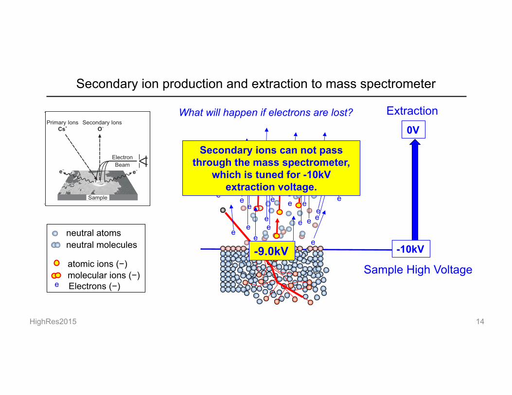
What will happen if electrons are lost?
Secondary ions can not pass through the mass spectrometer,
which is tuned for -10kV extraction voltage.
-9.9kV -9.5kV -9.0kV
Secondary ion production and extraction to mass spectrometer
HighRes2015 15
IMS 1280
Secondary Ions
Electron
Beam ?e?e
Primary Ions+Cs
Sample
?O
Electrostatic Lens
Electrostatic Deflector
Aperture or Slit
Collector
Motion Axis
Flight
Tube
Energy Slit
Primary Beam
Mass Filter
Field Aperture
Entrance Slit and
Contrast Aperture
Normal Incidence
Electron Gun
Airlock
Sample Stage
Sample
Duo-
Plasmatron
Cs-
Source
Detectors
Magnet
Electrostatic
Analyzer (ESA)
0V
-10kV atomic ions (−)
neutral atoms
molecular ions (−)
neutral molecules
Electrons (−) e
Extraction
Sample High Voltage
e
e e
e
e e e e
e
e
e
e e e
e
e
e
e e
e e
e e
e e
e
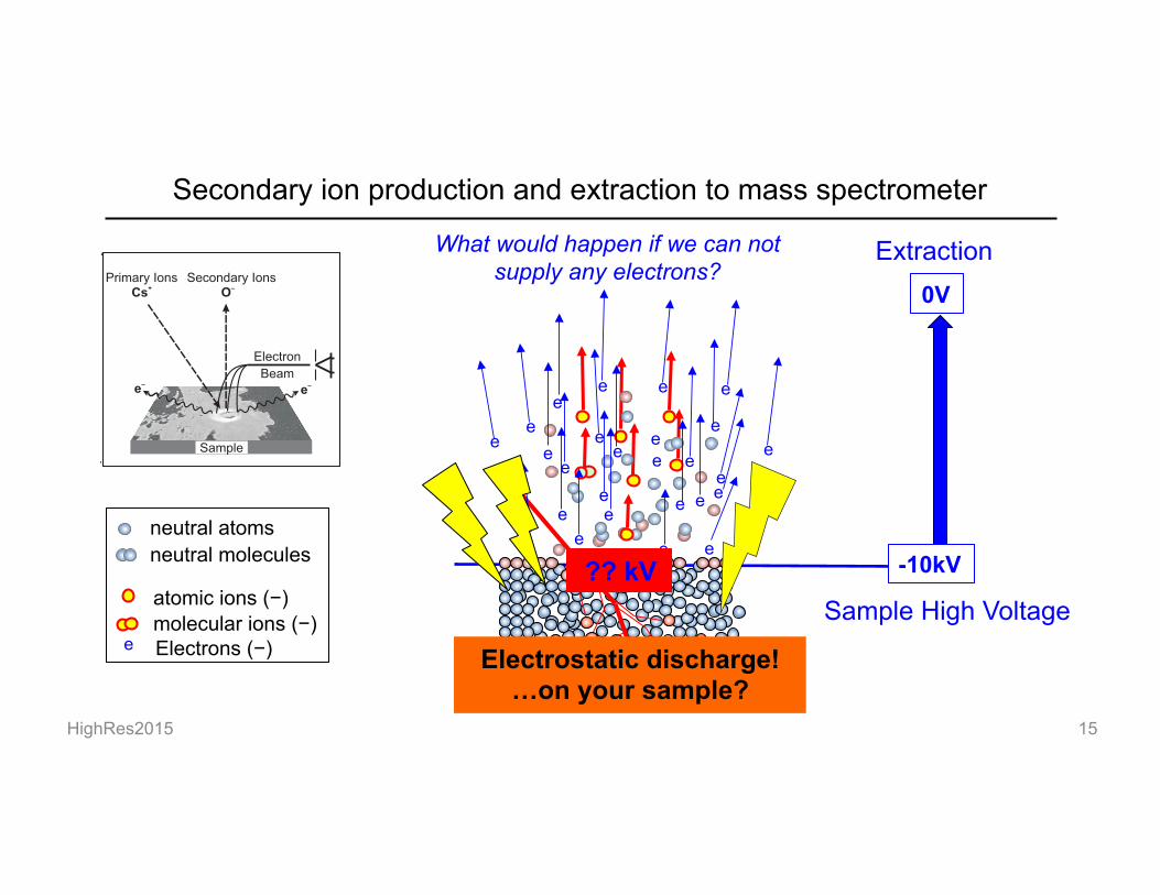
What would happen if we can not supply any electrons?
?? kV
Electrostatic discharge! …on your sample?

Electron Gun for Charge Compensation
HighRes2015 16 IMS 1280
Secondary Ions
Electron
Beam ?e?e
Primary Ions+Cs
Sample
?O
Electrostatic Lens
Electrostatic Deflector
Aperture or Slit
Collector
Motion Axis
Flight
Tube
Energy Slit
Primary Beam
Mass Filter
Field Aperture
Entrance Slit and
Contrast Aperture
Normal Incidence
Electron Gun
Airlock
Sample Stage
Sample
Duo-
Plasmatron
Cs-
Source
Detectors
Magnet
Electrostatic
Analyzer (ESA)
Electron Gun

HighRes2015 17
0V
Deceleration
Electron Cloud (50µA, 100-150µm): electron energy =0 eV
e e e e
e e e e e
e e
e e
e e e e
e e e e e
e e e e e
e e e e
electron is attracted to sample surface until the charge is compensated.
+++++++ When charge build up by sputtering
Acceleration voltage: -10kV
-10kV
Electron gun: -10 kV Sample acceleration: -10 kV
Sample
Electron Gun for Charge Compensation
IMS 1280
Secondary Ions
Electron
Beam ?e?e
Primary Ions+Cs
Sample
?O
Electrostatic Lens
Electrostatic Deflector
Aperture or Slit
Collector
Motion Axis
Flight
Tube
Energy Slit
Primary Beam
Mass Filter
Field Aperture
Entrance Slit and
Contrast Aperture
Normal Incidence
Electron Gun
Airlock
Sample Stage
Sample
Duo-
Plasmatron
Cs-
Source
Detectors
Magnet
Electrostatic
Analyzer (ESA)

Double Focusing Mass Spectrometer
HighRes2015 18 IMS 1280
Secondary Ions
Electron
Beam ?e?e
Primary Ions+Cs
Sample
?O
Electrostatic Lens
Electrostatic Deflector
Aperture or Slit
Collector
Motion Axis
Flight
Tube
Energy Slit
Primary Beam
Mass Filter
Field Aperture
Entrance Slit and
Contrast Aperture
Normal Incidence
Electron Gun
Airlock
Sample Stage
Sample
Duo-
Plasmatron
Cs-
Source
Detectors
Magnet
Electrostatic
Analyzer (ESA)
ESA Magnet

HighRes2015 19
Initial Kinetic Energy of Secondary Ions
Sputtering process may provide initial kinetic energy to ions
-10kV
0V
Ion without initial kinetic energy
Acceleration by electrostatic field Vs
mivi2/2 =qeVs vi
Ion with initial kinetic energy and angles
v0
v = vi + v0
Trajectory of ions with variable energies and angles will be different
Sample

HighRes2015 20
Electrostatic Analyzer (ESA)
IMS 1280
Secondary Ions
Electron
Beam ?e?e
Primary Ions+Cs
Sample
?O
Electrostatic Lens
Electrostatic Deflector
Aperture or Slit
Collector
Motion Axis
Flight
Tube
Energy Slit
Primary Beam
Mass Filter
Field Aperture
Entrance Slit and
Contrast Aperture
Normal Incidence
Electron Gun
Airlock
Sample Stage
Sample
Duo-
Plasmatron
Cs-
Source
Detectors
Magnet
Electrostatic
Analyzer (ESA)
ESA
Energy slit
faster ions
slower ions
ESA
Energy Slit
Ions with variable angles
ESA
Energy Slit
Ions with variable energy
Ions with variable angles: Focus Ions with variable energy: Dispersion Focus
Dispersion

Magnet
Exit slit
HighRes2015 21
Sector Magnet: Ions with different masses
IMS 1280
Secondary Ions
Electron
Beam ?e?e
Primary Ions+Cs
Sample
?O
Electrostatic Lens
Electrostatic Deflector
Aperture or Slit
Collector
Motion Axis
Flight
Tube
Energy Slit
Primary Beam
Mass Filter
Field Aperture
Entrance Slit and
Contrast Aperture
Normal Incidence
Electron Gun
Airlock
Sample Stage
Sample
Duo-
Plasmatron
Cs-
Source
Detectors
Magnet
Electrostatic
Analyzer (ESA)
Magnet
Exit slit
m
m-1 m+1
Magnet separate ions with different mass
Magnet
Exit slit
HighRes2015 22
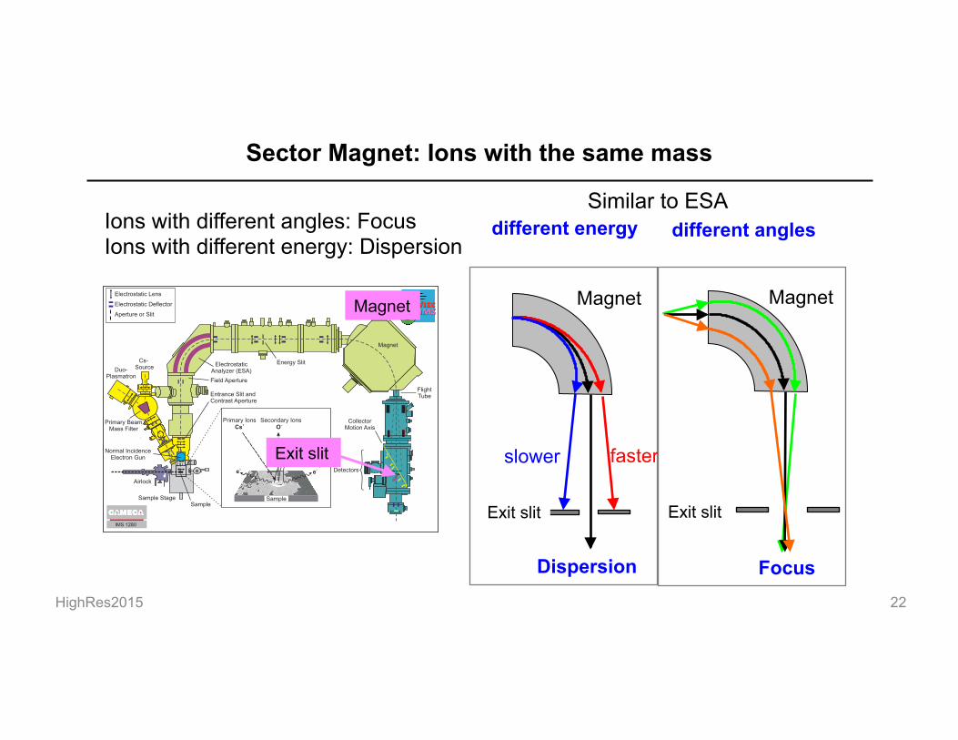
Sector Magnet: Ions with the same mass
IMS 1280
Secondary Ions
Electron
Beam ?e?e
Primary Ions+Cs
Sample
?O
Electrostatic Lens
Electrostatic Deflector
Aperture or Slit
Collector
Motion Axis
Flight
Tube
Energy Slit
Primary Beam
Mass Filter
Field Aperture
Entrance Slit and
Contrast Aperture
Normal Incidence
Electron Gun
Airlock
Sample Stage
Sample
Duo-
Plasmatron
Cs-
Source
Detectors
Magnet
Electrostatic
Analyzer (ESA)
Magnet
Exit slit slower faster
different energy
Magnet
Exit slit
different angles Ions with different angles: Focus Ions with different energy: Dispersion
Similar to ESA
Focus Dispersion

HighRes2015 23
Double focusing mass spectrometer
Focus Ions with variable initial energy Focus ions with variable angles
Dispersions made by ESA and Magnet are coupled to focus ions with variable energy.
From Cameca IMS manual
Ions ejected with variable angles and energy
Magnet ESA
Ions ejected with variable angles
Energy slit
lens
Entrance slit
Exity slit

HighRes2015 24
Detailed schematics of IMS 1280 Primary Column Magnet (PBMF) Lens: 5 Deflector: 7 Stigmator: 2 Aperture: 2
Secondary optics Magnet ESA Lens: 10 Deflector: 6 Stigmator: 3 Hexapole: 3 Slit: 3 Aperture: 2 Detectors FC: 6 EM: 4 MCP ESA: 6
Electron Gun Coil: 2 Lens: 1 Deflector: 2 Quadrapole: 1

HighRes2015 25
Mass Spectrum and Stability (NMR)
17O: MRP ~ 4,000; 16O, 18O: MRP ~2,200
17O
16OH +0.0036 amu
18O
16O
0.0045 amu 10% height
Magnetic field is regulated by NMR sensor. Drift (ΔB) <5 ppm for 12 hours
Hall Probe
NMR Probe
NMR Probes
Flight Tube
NMR (Nuclear Magnetic Resonance) sensors between electro-magnets
*Hall Probe stability: ~30 ppm for 1 hour
MRP=(M/ΔM): mass resolving power
30 ppm
Multi-collectors

HighRes2015 26
Ion Transmission
Transmission vs. Mass resolution
0.01
0.10
1.00
10.00
100 1000 10000 100000Mass resolution
Re
lati
ve
tra
ns
mis
sio
n
IMS 6f (Cs+)
IMS 1270 (Cs+)
Nanosims 50 (C-)
CAMECA
17O 18O/16O
WiscSIMS IMS 1280
§ Oxygen 2 isotope >90%
§ C isotope >90%
§ Oxygen 3 isotope >70%
Large radius SIMS
Small radius SIMS

HighRes2015 27
Ion Detectors
§ FC (Faraday cup): Direct ion current measurements >106 cps
§ EM (electron multiplier): Pulse counting <106 cps
Series of dynodes (N~20): each ejects 2-3 electrons 108 electrons produced per single ion – detected as an electronic pulse
Stable Gain Slower response (sec) Thermal noise (~1000 cps) Amp
Ion current 2×10⁹ cps = 3×10-11 A
R =1011 ohm
V = I × R
3V
Low noise <0.01 cps Fast response (20-70 ns) Gain drift
HighRes2015 28
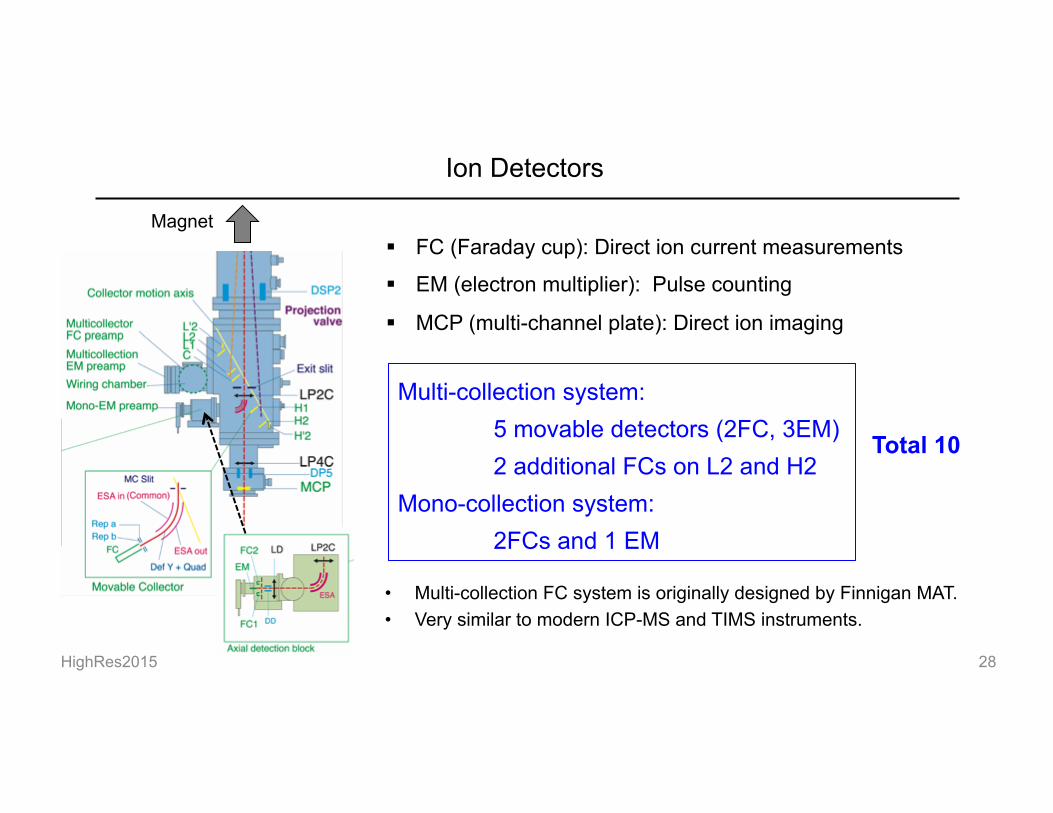
Ion Detectors
§ FC (Faraday cup): Direct ion current measurements
§ EM (electron multiplier): Pulse counting
§ MCP (multi-channel plate): Direct ion imaging
• Multi-collection FC system is originally designed by Finnigan MAT. • Very similar to modern ICP-MS and TIMS instruments.
Magnet
Multi-collection system: 5 movable detectors (2FC, 3EM) 2 additional FCs on L2 and H2
Mono-collection system: 2FCs and 1 EM
Total 10
HighRes2015 29
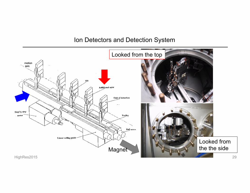
Ion Detectors and Detection System
!Looked from the the side
Looked from the top
Magnet

HighRes2015 30
Types of analyses using SIMS
Spot analysis: High precision stable isotope analyses Trace element analyses
Scanning Ion Imaging (SII): NanoSIMS
Trace element, isotope mapping Resolution = Primary beam size (0.5µm - 3 µm)
Direct Ion Image:
IMS 1280/7f series works as “ion microscope”. MCP detection SCAPS detector (Hokkaido 1270 and Hawaii 1280) Resolution = Optical resolution (~0.5 µm)
Example of SII (Ushikubo et al. 2008)

HighRes2015 31
Modification of WiscSIMS IMS 1280: 6 holder airlock system (2009)
Option from Cameca: Original system only keeps one additional sample.
§ Reduced time for pumping individual samples § Especially important for modern bio-minerals containing
more moistures and organic matters
HighRes2015 32
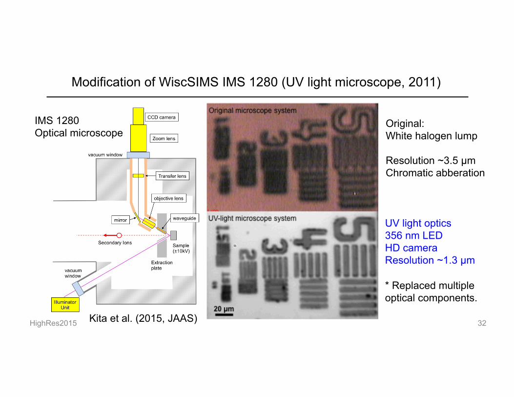
Modification of WiscSIMS IMS 1280 (UV light microscope, 2011)
Kita et al. (2015, JAAS)
IMS 1280 Optical microscope
Original: White halogen lump Resolution ~3.5 µm Chromatic abberation
UV light optics 356 nm LED HD camera Resolution ~1.3 µm * Replaced multiple optical components.

HighRes2015 33
New sample viewing software “Badgerscope©” (2012)
Kita et al. (2015, JAAS)
Image processing
New software to view HD-camera
HighRes2015 34
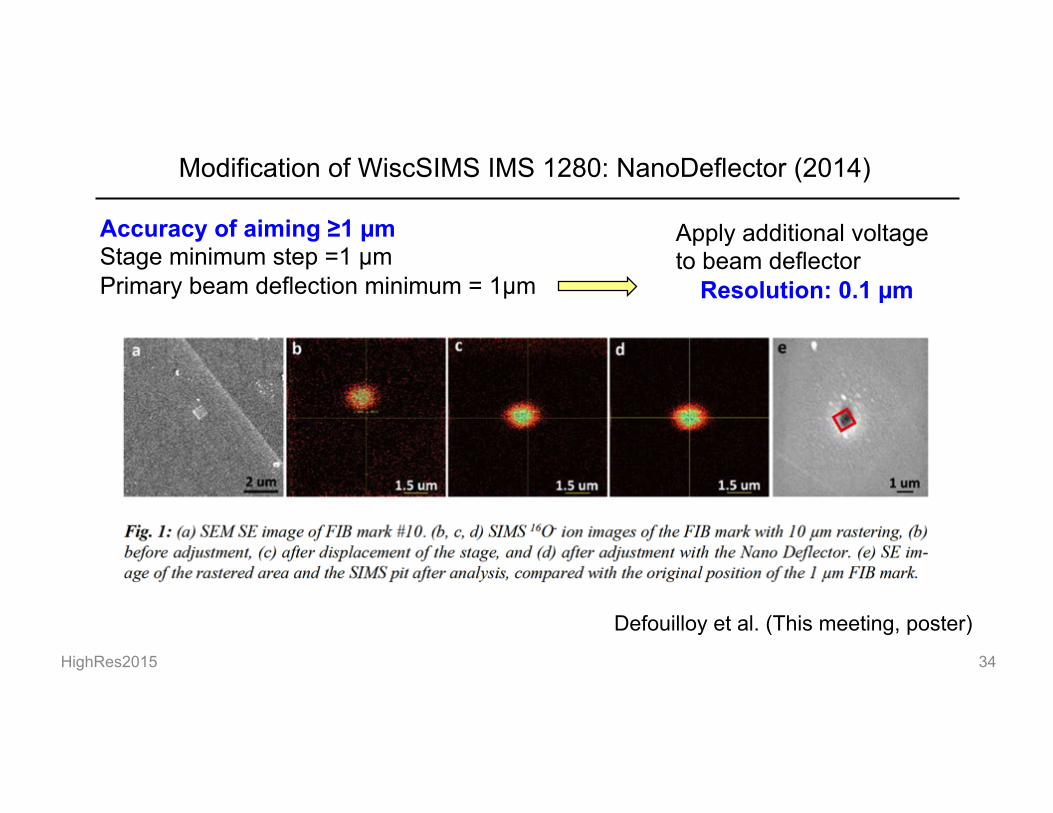
Modification of WiscSIMS IMS 1280: NanoDeflector (2014)
Defouilloy et al. (This meeting, poster)
Accuracy of aiming ≥1 µm Stage minimum step =1 µm Primary beam deflection minimum = 1µm
Apply additional voltage to beam deflector
Resolution: 0.1 µm
HighRes2015 35
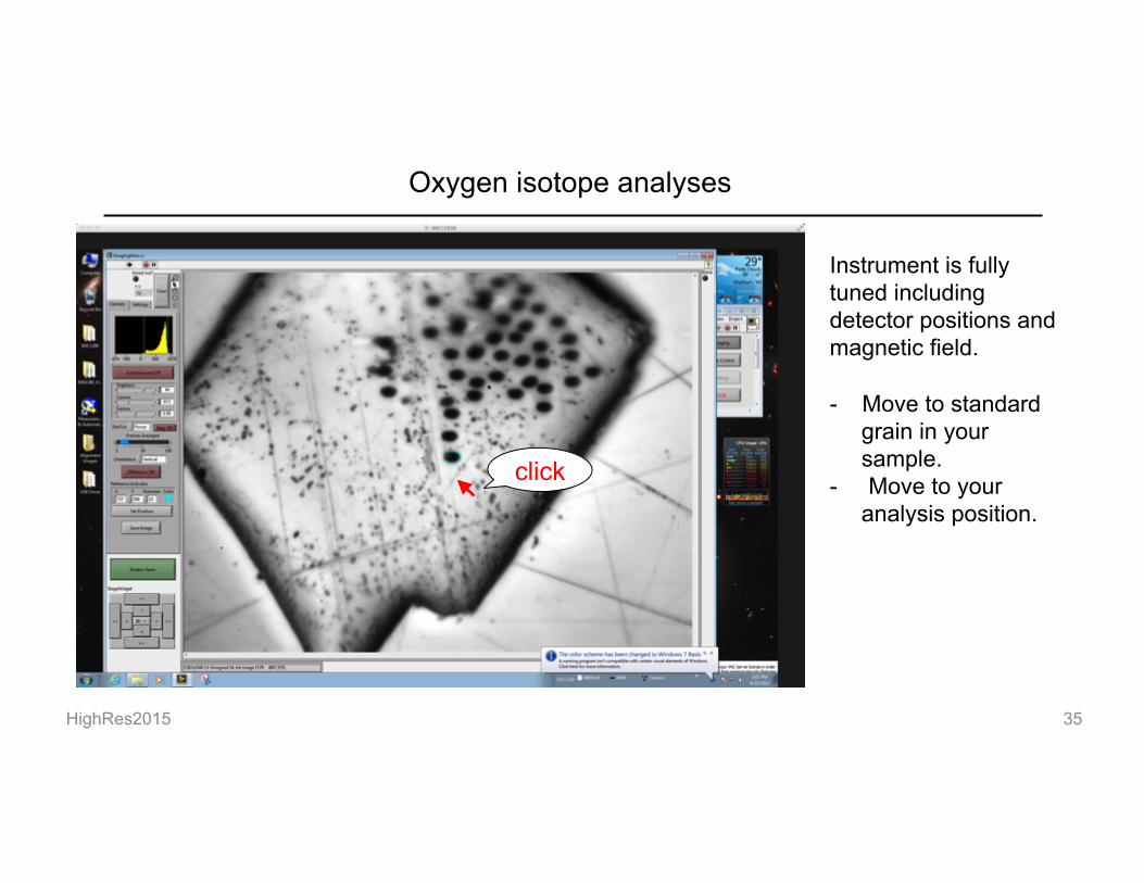
Oxygen isotope analyses
Instrument is fully tuned including detector positions and magnetic field. - Move to standard
grain in your sample.
- Move to your analysis position.
click

36
Oxygen isotope analyses
Instrument is fully tuned including detector positions and magnetic field. - Move to standard
grain in your sample.
- Move to your analysis position.
- Press START
Acquisition takes 3min
HighRes2015

37
Oxygen isotope analyses
During first 1 min, there will be series of scanning. This is called “DTFA Scan” that adjustment of primary beam misalignment against secondary ion optical axis.
Cs+
O-
DTFA (XY)
DTFA-Scan
HighRes2015

38
After the analysis: import new data to excel sheet
HighRes2015
Select next row
Click Macro-button

39
After the analysis: import new data to excel sheet
HighRes2015

HighRes2015 40
Oxygen isotope analyses
Instrument is fully tuned including detector positions and magnetic field. - Move to standard
grain in your sample.
- Move to your analysis position.
- Move to next position
click
Repeat this 12 hours