Tutorial April 2016- - PSIM Electronic Simulation … · 2016-12-29 · Peak Current Mode Control -...
13
Peak Current Mode Control Tutorial –April 2016-
Transcript of Tutorial April 2016- - PSIM Electronic Simulation … · 2016-12-29 · Peak Current Mode Control -...
Peak Current Mode Control
Tutorial –April 2016-

How to Contact:
www.powersmartcontrol.com
This SmartCtrl© Tutorial by Carlos III University is licensed under a Creative Commons Attribution 4.0
International License:
You are free to:
Share — copy and redistribute the material in any medium or format
Adapt — remix, transform, and build upon the material for any purpose, even commercially.
The licensor cannot revoke these freedoms as long as you follow the license terms.
Under the following terms:
Attribution — You must give appropriate credit, provide a link to the license, andindicate if
changes were made. You may do so in any reasonable manner, but not in any way that suggests
the licensor endorses you or your use.
No additional restrictions — You may not apply legal terms or technological measures that
legally restrict others from doing anything the license permits.
Based on a work at www.powersmartcontrol.com
SmartCtrl© 2009-2016 by Carlos III University of Madrid. GSEP Power Electronics Systems Group
The software SmartCtrl© described in this manual is furnished under a license agreement. The software may be used or
copied only under the terms of the license agreement.

Peak Current Mode Control
- 2 -
Peak Current Mode Control Tutorial V2.0 – April 2016 www.powersmartcontrol.com
Table of contents
1. Introduction ............................................................................................. 3
2. Buck converter design ................................ ¡Error! Marcador no definido.
3. Design validation ........................................ ¡Error! Marcador no definido.
Peak Current Mode Control
- 3 -
Peak Current Mode Control Tutorial V2.0 – April 2016 www.powersmartcontrol.com
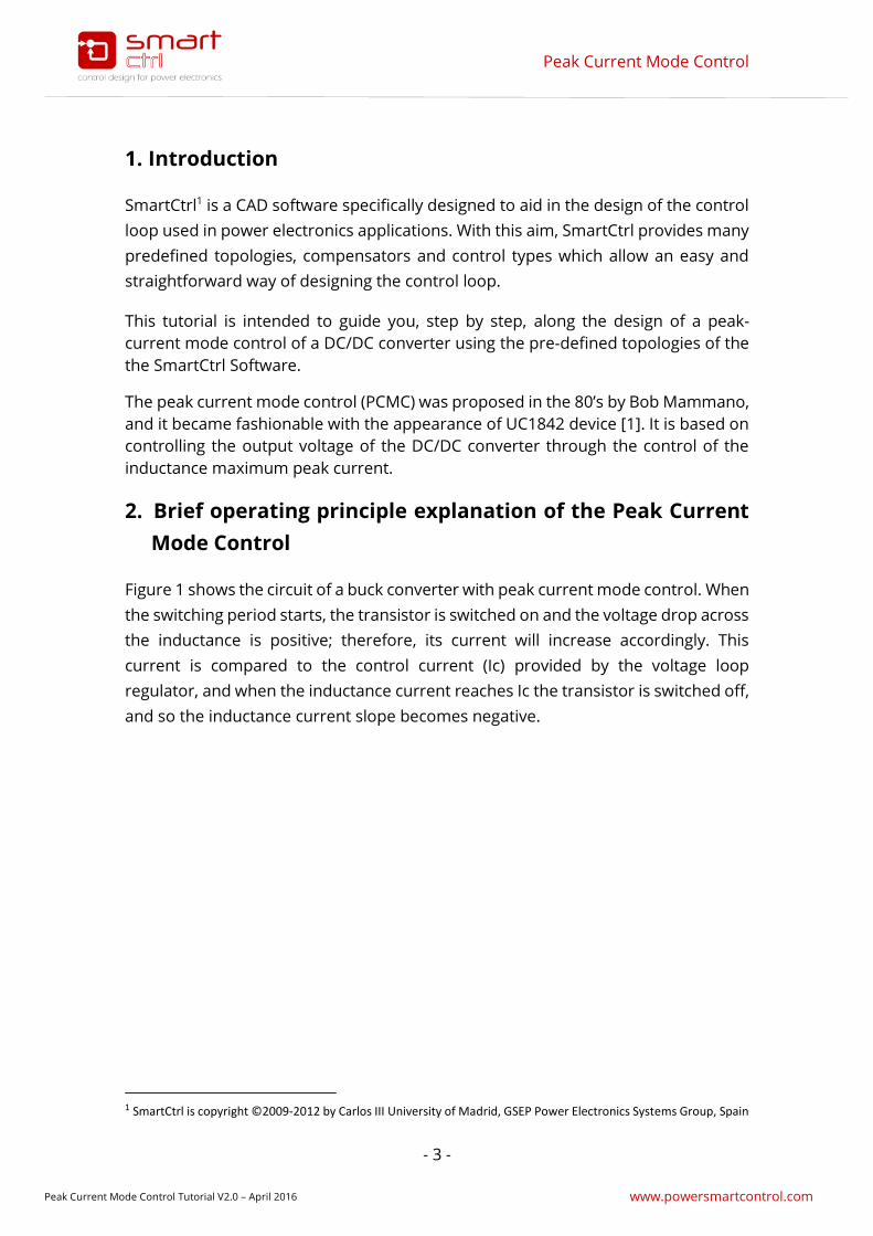
1. Introduction
SmartCtrl1 is a CAD software specifically designed to aid in the design of the control
loop used in power electronics applications. With this aim, SmartCtrl provides many
predefined topologies, compensators and control types which allow an easy and
straightforward way of designing the control loop.
This tutorial is intended to guide you, step by step, along the design of a peak-
current mode control of a DC/DC converter using the pre-defined topologies of the
the SmartCtrl Software.
The peak current mode control (PCMC) was proposed in the 80’s by Bob Mammano,
and it became fashionable with the appearance of UC1842 device [1]. It is based on
controlling the output voltage of the DC/DC converter through the control of the
inductance maximum peak current.
2. Brief operating principle explanation of the Peak Current
Mode Control
Figure 1 shows the circuit of a buck converter with peak current mode control. When
the switching period starts, the transistor is switched on and the voltage drop across
the inductance is positive; therefore, its current will increase accordingly. This
current is compared to the control current (Ic) provided by the voltage loop
regulator, and when the inductance current reaches Ic the transistor is switched off,
and so the inductance current slope becomes negative.
1 SmartCtrl is copyright ©2009-2012 by Carlos III University of Madrid, GSEP Power Electronics Systems Group, Spain
Peak Current Mode Control
- 4 -
Peak Current Mode Control Tutorial V2.0 – April 2016 www.powersmartcontrol.com
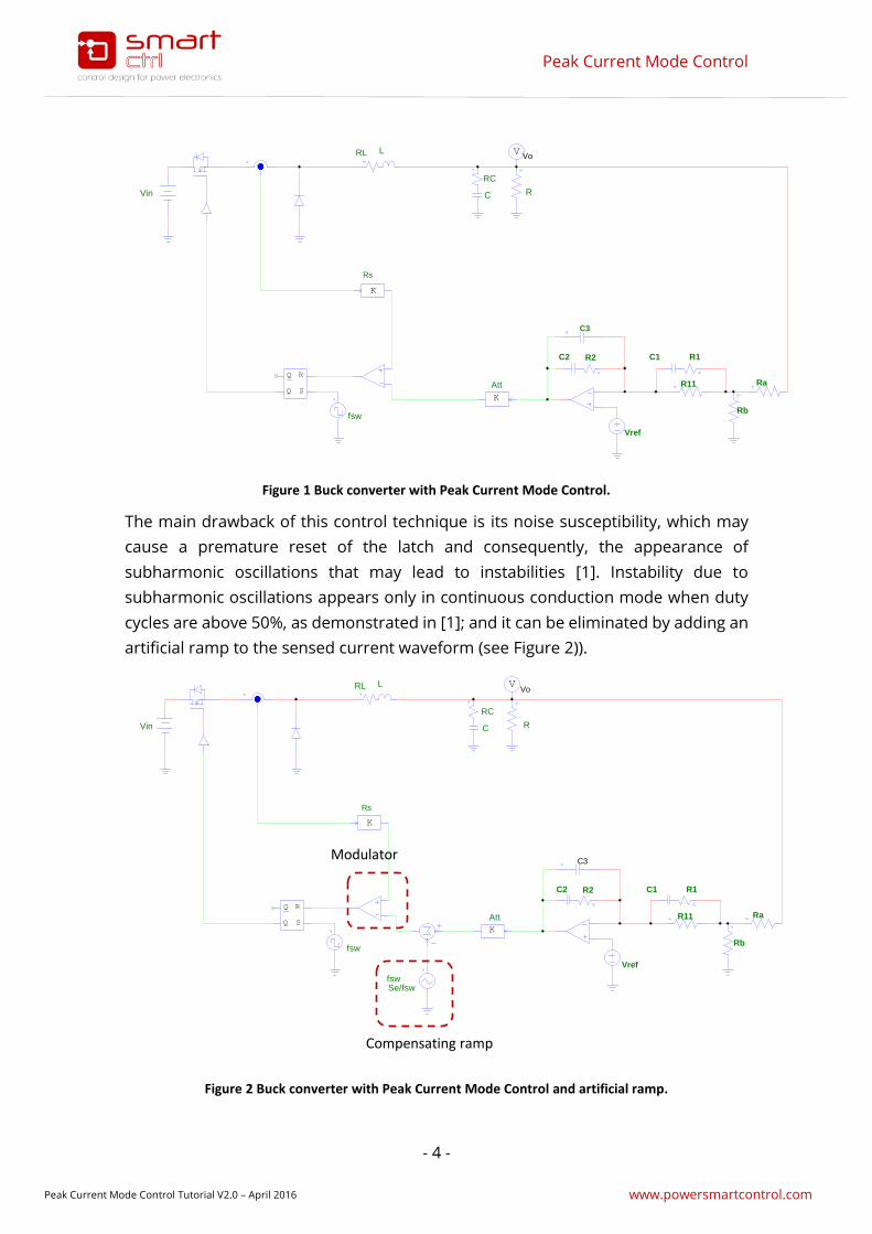
Figure 1 Buck converter with Peak Current Mode Control.
The main drawback of this control technique is its noise susceptibility, which may
cause a premature reset of the latch and consequently, the appearance of
subharmonic oscillations that may lead to instabilities [1]. Instability due to
subharmonic oscillations appears only in continuous conduction mode when duty
cycles are above 50%, as demonstrated in [1]; and it can be eliminated by adding an
artificial ramp to the sensed current waveform (see Figure 2)).
Figure 2 Buck converter with Peak Current Mode Control and artificial ramp.
LRL
C
RC
RVin
S
R
Q
Q
fsw
VVo
K
Rs
K
Att
Vref
C2 R2
Rb
RaR11
C3
R1C1
RL L
RC
C RVin
S
R
Q
Q
fsw
VVo
K
Rs
fswSe/fsw
K
Att
Vref
R2C2
Rb
RaR11
C3
C1 R1
Compensating ramp
Modulator

Peak Current Mode Control
- 5 -
Peak Current Mode Control Tutorial V2.0 – April 2016 www.powersmartcontrol.com
3. Let’s design a Peak Current Mode Control with SmartCtrl.
Within the pre-defined control strategies provided by SmartCtrl, you can find the
Peak Current Mode Control. This control strategy can be applied to any of the pre-
defined DC/DC converters included in SamrtCtrl: Buck, Boost, Buck-Boost, Flyback
and Forward. Along this tutorial, the peak current mode control is going to be
applied to a buck converter. Let´s start a step by step configuration of this system.
To access the configuration window of the Peak Current Mode Control, there are
three possible paths:
1. Click on the remarked icon and then on the DC/DC converter – Peak Current
mode control button.
Figure 3 Start a peak current mode control. Option 1.
2. Click on the Design drop-down menu, DC/DC converters, Peak Current Mode
Control.

Peak Current Mode Control
- 6 -
Peak Current Mode Control Tutorial V2.0 – April 2016 www.powersmartcontrol.com
Figure 4 Start a peak current mode control. Option 2.
3. Click on the peak current mode control icon.
Figure 5 Start a peak current mode control. Option 3.
Regardless the starting option, the configuration process is exactly the same and it
is explained along the following paragraphs.
Step 1: Select one of the pre-defined DC/DC converters.
Figure 6 Starting window for the Peak current mode control.
Peak Current Mode Control
- 7 -
Peak Current Mode Control Tutorial V2.0 – April 2016 www.powersmartcontrol.com
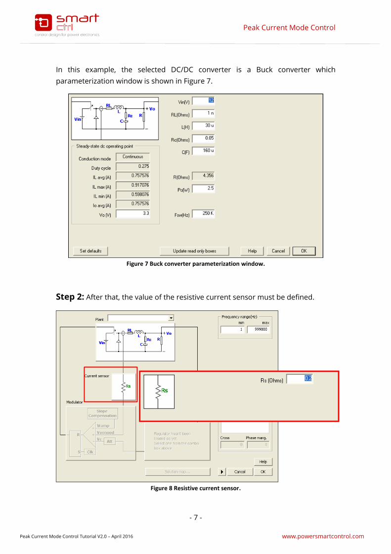
In this example, the selected DC/DC converter is a Buck converter which
parameterization window is shown in Figure 7.
Figure 7 Buck converter parameterization window.
Step 2: After that, the value of the resistive current sensor must be defined.
Figure 8 Resistive current sensor.

Peak Current Mode Control
- 8 -
Peak Current Mode Control Tutorial V2.0 – April 2016 www.powersmartcontrol.com
Step 3: Then, define the modulator parameters.
Figure 9 Modulator design in a peak current mode control (PCMC).
From top to bottom, the modulator input signals are de following:
Vramp is the characteristic compensation slope used with this type of
control technique. This compensation slope is added to the inductance
current in order to ensure the system stability when duty cycles are above
50%.
Vsensed is the equivalent voltage of the sensed inductance current.
Vc is the sensed regulator output voltage
Regarding the modulator design criteria, they are defined below:
Sn The inductance charge slope.
Sf The inductance discharge slope.
Se The slope of the compensation ramp, it is computed as function of
Sn and Sf.
Att Is the attenuation applied to the regulator output voltage
Peak Current Mode Control
- 9 -
Peak Current Mode Control Tutorial V2.0 – April 2016 www.powersmartcontrol.com
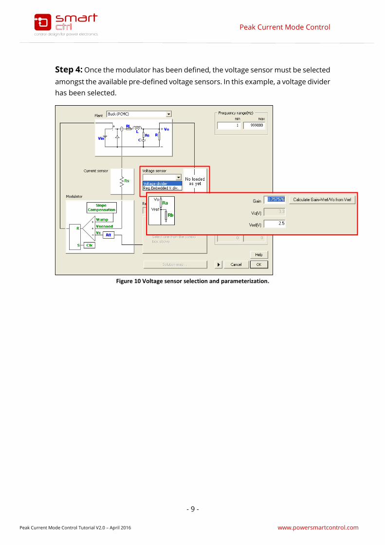
Step 4: Once the modulator has been defined, the voltage sensor must be selected
amongst the available pre-defined voltage sensors. In this example, a voltage divider
has been selected.
Figure 10 Voltage sensor selection and parameterization.
Peak Current Mode Control
- 10 -
Peak Current Mode Control Tutorial V2.0 – April 2016 www.powersmartcontrol.com
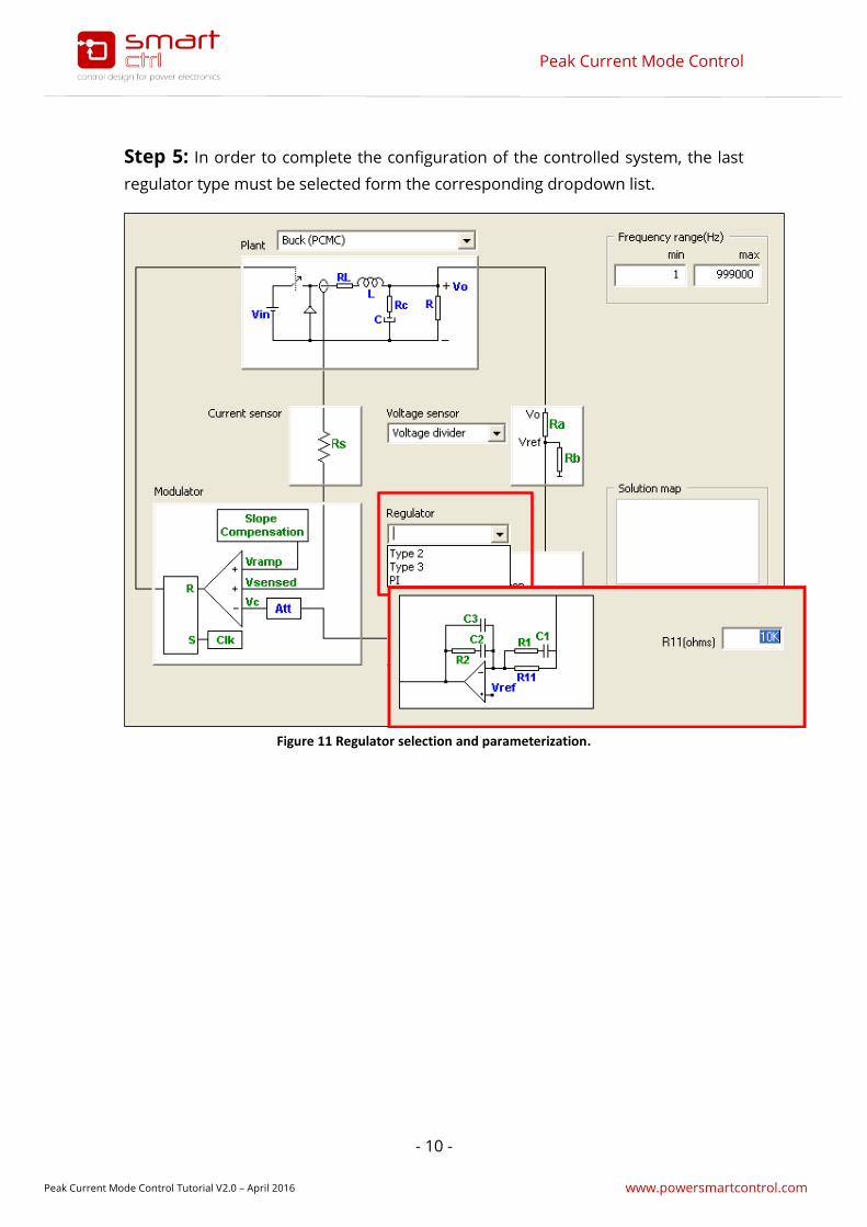
Step 5: In order to complete the configuration of the controlled system, the last
regulator type must be selected form the corresponding dropdown list.
Figure 11 Regulator selection and parameterization.
Peak Current Mode Control
- 11 -
Peak Current Mode Control Tutorial V2.0 – April 2016 www.powersmartcontrol.com
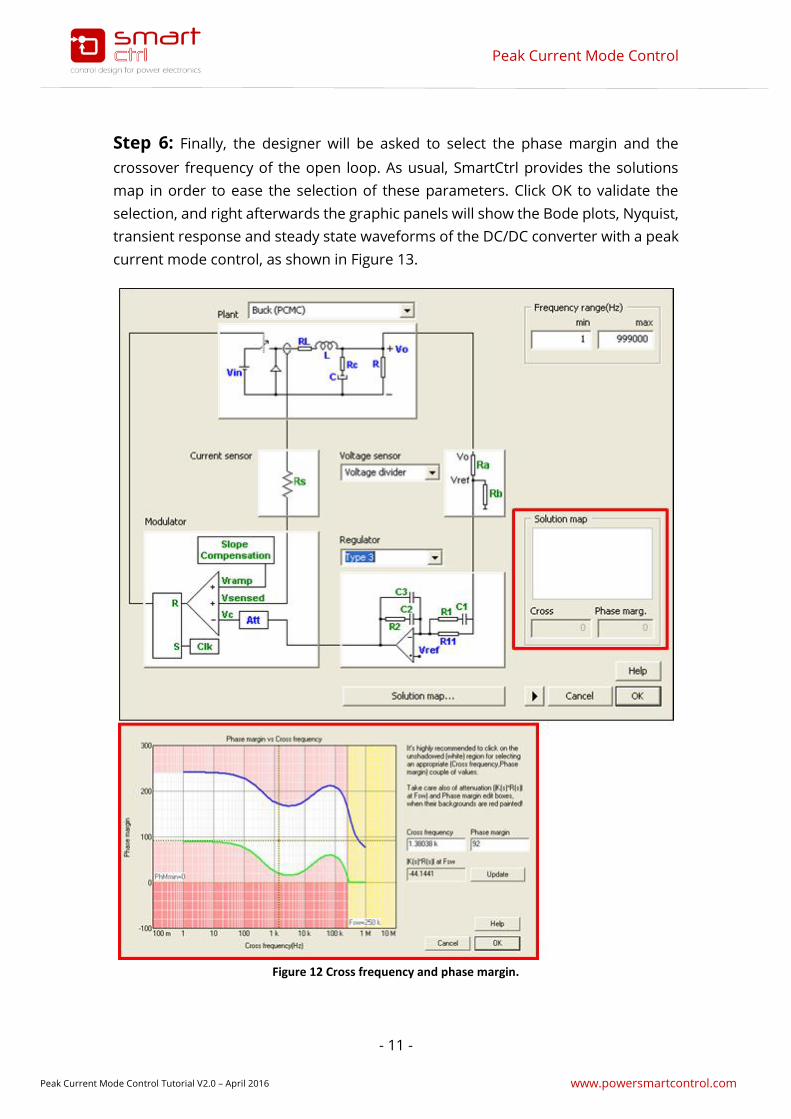
Step 6: Finally, the designer will be asked to select the phase margin and the
crossover frequency of the open loop. As usual, SmartCtrl provides the solutions
map in order to ease the selection of these parameters. Click OK to validate the
selection, and right afterwards the graphic panels will show the Bode plots, Nyquist,
transient response and steady state waveforms of the DC/DC converter with a peak
current mode control, as shown in Figure 13.
Figure 12 Cross frequency and phase margin.

Peak Current Mode Control
- 12 -
Peak Current Mode Control Tutorial V2.0 – April 2016 www.powersmartcontrol.com
At any time, the user can change the parameterization of the system and the results
will be updated accordingly. To change the parameterization, just click on one of the
remarked icons shown in Figure 13.
Figure 13 Graphic panels.
4. Bibliography
[1] “Voltage-Mode, Current-Mode (and Hysteretic Control)”, Microsemi Technical
Note TN-203, Sanjaya Maniktala, 2012
[2] “Fundamentals of Power Electronics”, Robert W. Erickson and Dragan
Maksimovic, Kluwer academic publishers, ISBN 0-7923-72-70-0.
Regulator designbox
Bode Plot Nyquist Diagram Steady – statewaveforms
Transient response
Either of this two icons show the designed converter.


![Cogui Tutorial Slides - Facts [Mode de compatibilité]](https://static.fdocuments.us/doc/165x107/617635f7161b827e9770f188/cogui-tutorial-slides-facts-mode-de-compatibilit.jpg)


![Tutorial Depressuring First [Compatibility Mode]](https://static.fdocuments.us/doc/165x107/545d5781b1af9f410a8b4af3/tutorial-depressuring-first-compatibility-mode.jpg)