Turkey Point, Units 3 & 4 - Nuclear Regulatory Commission · A. Survey Coordinator (i.e., contact...
133
AUG 2 0 2007 1PL L-2007-129 10CFR50, Appendix E US Nuclear Regulatory Commission Attn: Document Control Desk Washington, DC, 20555-00001 Re: Turkey Point Units 3 and 4 Docket Nos. 50-250 and 50-251 Emergency Response Data System (ERDS) Maintenance This letter is being submitted pursuant to 10CFR50, Appendix E, VI, 3.b, "Maintaining the Emergency Response Data System," for Turkey Point Units 3 and 4 due to ERDS Point identification (ID) revisions. Turkey Point Unit 3 (TP3) will be undergoing a major modification (i.e., replacement) of the Emergency Response Data Acquisition and Display System (ERDADS) during the September, 2007 Refueling Outage. The ERDADS is the plant computer system that supplies the ERDS data points (as described in NUREG-1394, Revision 1). The TP3 ERDS Data Point Library (DPL) will retain all the original data points (i.e., 61 data points) but will revise the Point IDs to a format that has been established for the new Distributed Control System (DCS) configured ERDADS (see Attachment 1). This Point ID change will affect the ERDS transmission format and computer communication protocol, therefore NRC notification is required 30 days prior to implementation. Implementation of this change is currently scheduled for September 25, 2007. This will require ERDS DPL point ID updates for TP3 by NRC personnel. Associated "detail" data for several of the points has also been updated to reflect current plant configuration. This too will require ERDS DPL updates for TP3 by NRC personnel. These changes as well as final ERDS testing will be overseen by vendors from Scientech LLC. The vendor will coordinate the Point ID change-over and testing between TP3 and the NRC Operations Center to minimize ERDS unavailability during this time. The ERDS replacement will be completed prior to TP3 resuming plant operation following the outage. The Turkey Point Unit 4 (TP4) ERDS will lose two data points during an interim period between the TP3 modification and the planned TP4 modification (currently scheduled for spring, 2008). These two data points, the plant vent gas activity monitor and liquid waste effluent monitor, will only be unavailable to TP4 ERDS and will be communicated to the NRC over the ENS telephones if required during this interim period. Associated "detail" data for several of the TP4 points has also been updated to reflect current plant configuration which will require NRC updating of the TP4 data base. Turkey Point's original submittal for ERDS compliance in July, 1992, included one (common) Plant Attribute Library (PAL) and two unit-specific DPLs (TP3 and TP4). This submittal updates the original submittal for ERDS compliance. PAL changes include an FPL Group company
Transcript of Turkey Point, Units 3 & 4 - Nuclear Regulatory Commission · A. Survey Coordinator (i.e., contact...

AUG 2 0 20071PL L-2007-129
10CFR50, Appendix E
US Nuclear Regulatory CommissionAttn: Document Control DeskWashington, DC, 20555-00001
Re: Turkey Point Units 3 and 4Docket Nos. 50-250 and 50-251Emergency Response Data System (ERDS) Maintenance
This letter is being submitted pursuant to 10CFR50, Appendix E, VI, 3.b, "Maintainingthe Emergency Response Data System," for Turkey Point Units 3 and 4 due to ERDSPoint identification (ID) revisions.
Turkey Point Unit 3 (TP3) will be undergoing a major modification (i.e., replacement) ofthe Emergency Response Data Acquisition and Display System (ERDADS) during theSeptember, 2007 Refueling Outage. The ERDADS is the plant computer system thatsupplies the ERDS data points (as described in NUREG-1394, Revision 1).
The TP3 ERDS Data Point Library (DPL) will retain all the original data points (i.e., 61data points) but will revise the Point IDs to a format that has been established for thenew Distributed Control System (DCS) configured ERDADS (see Attachment 1). ThisPoint ID change will affect the ERDS transmission format and computer communicationprotocol, therefore NRC notification is required 30 days prior to implementation.Implementation of this change is currently scheduled for September 25, 2007. This willrequire ERDS DPL point ID updates for TP3 by NRC personnel.
Associated "detail" data for several of the points has also been updated to reflect currentplant configuration. This too will require ERDS DPL updates for TP3 by NRC personnel.
These changes as well as final ERDS testing will be overseen by vendors fromScientech LLC. The vendor will coordinate the Point ID change-over and testingbetween TP3 and the NRC Operations Center to minimize ERDS unavailability duringthis time. The ERDS replacement will be completed prior to TP3 resuming plantoperation following the outage.
The Turkey Point Unit 4 (TP4) ERDS will lose two data points during an interim periodbetween the TP3 modification and the planned TP4 modification (currently scheduled forspring, 2008). These two data points, the plant vent gas activity monitor and liquidwaste effluent monitor, will only be unavailable to TP4 ERDS and will be communicatedto the NRC over the ENS telephones if required during this interim period. Associated"detail" data for several of the TP4 points has also been updated to reflect current plantconfiguration which will require NRC updating of the TP4 data base.
Turkey Point's original submittal for ERDS compliance in July, 1992, included one(common) Plant Attribute Library (PAL) and two unit-specific DPLs (TP3 and TP4). Thissubmittal updates the original submittal for ERDS compliance. PAL changes include
an FPL Group company

L-2007-129Page 2 of 2
plant contact information and new TP3 hardware and software information. In addition,the DPLs list the new TP3 configuration and the "interim" TP4 configuration. The TP4changes do not affect NRC reception of the transmitted data (See Attachments 2, 3and 4).
Current scheduling for outage work on the ERDADS (and ERDS) is from September 3,2007 through October 1, 2007. This activity will be separately communicated to theNRC just prior to the plant outage in accordance with 1OCFR50.72 (b) (3) (viii) and willinclude notification of the NRC resident inspector and any follow up notifications as maybe required.
This information is being provided for both compliance to10CFR50, Appendix E, VI, 3.aand 3.b requirements and to support implementation by the NRC of the new TP3 ERDSData Point IDs.
Should there be any questions, please contact James Connolly, Licensing Manager, at305-246-6632.
Very truly yours,
William J erson, r.
Vice PresidentTurkey Point Nuclear Plant
Attachments
cc: Regional Administrator, Region II, USNRCSenior Resident Inspector, USNRC, Turkey Point Plant

ATTACHMENT 1
TURKEY POINT UNIT 3
ERDS DATA PARAMETER
POINT ID CHANGES

L-2007-129Attachanent 1
Page 1 of 2
TP3 ERDS Data Parameter Point IDsItem # Original Point ID New DCS Point ID Description
1 NIAVPRLVL-3 NIAVPRL V POWER RANGE POWER LEVEL (AVG)
2 NIAVSRLVL-3 NIAVSRL V SOURCE RANGE POWER LVL (AVG)3 INTERMEDIATE RANGE POWER LVLNIAVIRLVL-3 NIAVIRL_ (AV
N V(AVG)4 NI6649AVPR-3 N6649AVP V GAMMA-METRICS AVE OF PR (AVG)5 N16649AVSR-3 N6649AVS V GAMMA-METRICS AVE OF SR (AVG)
6 RXHDLVLLO-3 RXHDLLOV REACTOR HEAD LEVEL (AUCT LOW)7 RXPLLVLLO-3 RXPLLLOV REACTOR PLENUM LEVEL (AUCT
LOW)8 CET-3 CET.V CORE EXIT TEMP (AUCT HIGH)9 SMMILO-3 SMM1LOV SUBCOOLING (AUCT LOW)10 RCSA-AVFLO-3 RCSA AVF V RCS A AVERAGE FLOW11 RCSB-AVFLO-3 RCSBAVF V RCS B AVERAGE FLOW12 RCSC-AVFLO-3 RCSC AVF V RCS C AVERAGE FLOW13 SGA-AVLVL-3 SGA AVL V STEAM GENERATOR LEVEL A (AVG)14 LT477-3 L477 A STM GEN A WIDE RANGE LEVEL15 SGB-AVLVL-3 SGBAVLV STEAM GENERATOR LEVEL B (AVG)16 LT487-3 L487 A STM GEN B WIDE RANGE LEVEL17 SGC-AVLVL-3 SGC AVL V STEAM GENERATOR LEVEL C (AVG)18 LT497-3 L497 A STM GEN C WIDE RANGE LEVEL19 STEAM GENERATOR PRESSURE ASGA-AVPRES-3 SGAAVP_ VAG- - (AVG)
20 STEAM GENERATOR PRESSURE BSGB-AVPRES-3 SGB AVP V(AG- - (AVG)
21 STEAM GENERATOR PRESSURE CSGC-AVPRES-3 SGCAVP V(AGA V F(AVG)
22 SGAAVFWFLO-3 SGAAVFWF V FEEDWATER FLOW A SG (AVG)23 SGBAVFWFLO-3 SGBAVFWF V FEEDWATER FLOW B SG (AVG)24 SGCAVFWFLO-3 SGCAVFWF V FEEDWATER FLOW C SG (AVG)
25 AUX FEEDWATER FLOW A SG U3SGAAFWFLO-3 SGAAFWFV (TOTAL)
26 AUX FEEDWATER FLOW B SG U3SGBAFWFLO-3 SGBAFWF V(TAL- (TOTAL)
27 AUX FEEDWATER FLOW C SG U3SGCAFWFLO-3 SGCAFWF V(TAL- (TOTAL)RCS HOT LEG A AVG TEMP
THA-AVTEMP-3 THA AVTP V28- -
29 THB-AVTEMP-3 THB AVTP V RCS HOT LEG B AVG TEMP30 THC-AVTEMP-3 THC AVTP V RCS HOT LEG C AVG TEMP

L-2007-129Attachment 1
Page 2 of 2
TP3 ERDS Data Parameter Point IDs (cont'd)Item # Original Point ID New DCS Point ID Description
31 TCA-AVTEMP-3) TCAAVTPV RCS COLD LEG A AVG TEMP32 TCB-AVTEMP-3 TCB AVTP V RCS COLD LEG B AVG TEMP33 TCC-AVTEMP-3 TCCAVTPV RCS COLD LEG C AVG TEMP34 RCSAVPRES-3 RCSAVPV RCS AVG WR PRESSURE35 PZR-AVLVL-3 PRZ AVLV PRESSURIZER AVERAGE LEVEL36 FT122-3 F122 A CHARGING FLOW37 FT932-3 F932 A HHSI FLO A HL INSIDE CNTMT38 FT933-3 F933_A HHSI FLO B HL INSIDE CNTMT39 FT943-3 F943 A HHSI TO BORON INJ TANK40 FT605-3 F605 A RHR SYSTEM FLOW41 CTMTHILVLL-3 CHILVLL V CNTMT SUMP WATER LEVEL (AUCT
LL HIGH)42 CNTMT HR WATER LEVEL (AUCT
CTMTHLVLH-3 CHILVLHV- HIGH)43 R14-3** R14 A** PLANT VENT GAS ACTIVITY RAD MON44 RAD6304HR-3 R6304HR A PLANT VENT GAS GAMMA HI RANGE45 RAD6304FLO-3 R6304FLO A PLANT VENT FLOW RATE46 RAD6418HR-3 R6418HR A U3 FUEL PIT GAS GAMMA HI RANGE47 R18-3** R18 A** LIQUID WASTE EFFLUENT RAD MON48 R15-3 R15 A CONDENSER GAS EJECTOR RAD MON49 RAD6417HR-3 R6417HRA AIR EJECTOR GAS GAMMA HI RANGE50 CTMHRADW-3 CHRADWV CNTMT WR RADIATION (AUCT HIGH)51 R20-3 R20_A RCS LETDOWN ACTIVITY RAD MON52 RAD6426-3 R6426 A MAIN STM LINES GAMMA HI RANGE53 R19-3 R19 A SG EFFLUENT PROCESS RAD MON54 CTMTAVPRSW-3 CAVPRSWV CNTMT WR AVG PRESSURE55 CTMTHITMP-3 C HITMP V CNTMT TEMP (AUCT HIGH)56 CTMTHZCONC-3 CHZCONCV CNTMT H2 CONCENTRATION (AUCT
- HIGH)
57 RWST3AVLVL-3 .RWSTAVLV RWST LEVEL (AUCT LOW)58 WS-0OM-TP-4 WSIOMLU A WIND SPEED 10 METERS (TP)59 WD-10M-TP-4 WDlOM LU A WIND DIRECTION 10 METERS (TP)60 D-TMP-B-SD-3 STABB SD A ESTIMATE OF ATMOS STABILITY61 FAN-3V21-3* FAN3V21 A* SPENT FUEL PIT EXHAUST FAN
* Digital Point** Common Point with Unit 4

ATTACHMENT 2
APPENDIX B
ERDS COMMUNICATIONS DESCRIPTION
AND SURVEY QUESTIONAIRE
TURKEY POINT UNITS 3 AND 4
PLANT ATTRIBUTE LIBRARY

L-2007-129Attachment 2
Page 1 of 5
I. CONTACTS
Note: Please provide name, title, mailing address, and phone number.
A. Survey Coordinator (i.e., contact for later clarification of questionnaireanswers):
Paul BanaszakFlorida Power & Light CompanyTurkey Point Nuclear Plant9760 SW 344 StHomestead, FL 33035305-246-6072
B. Computer Hardware Specialist(s):
Billy J WoodERDADSFlorida Power & Light CompanyTurkey Point Nuclear Plant9760 SW 344 StHomestead, FL 33035305-246-6669
C. Systems Software Specialist(s)
Paul Banaszak(see above)
D. Application-level Software Specialist(s):
Paul Banaszak(see above)
E. Telephone Systems Specialist(s):
Tom LiberatoreManagement Information System SupervisorFlorida Power & Light CompanyTurkey Point Nuclear Plant9760 SW 344 StHomestead, FL 33035305-246-4634

L-2007-129Attachment 2
Page 2 of 5
II. ERDS COMMUNICATIONS DESCRIPTION
A. Hardware
FPL Turkey Point Nuclear Plant will be a single-feeder site.
B. Software
There are no exceptions to the information described in NUREG-1394, Rev. IAppendix B, Section II, ERDS Communications Description (Pages B-3 throughB-6).
III. SELECTION OF DATA FEEDERS
A. How many data feeders are there (six maximum)?
FPL Turkey Point Nuclear Plant will use a single data feeder for each unit.
B. Identify the selected data feeders and provide the following for each:
1. a short description of the categories of data points it will provide (e.g.,MET, Rad, or plant data points, by unit) and,
2. the rationale for selecting if another system can also provide its categoriesof data points.
The plant computer system is the Emergency Response Data Acquisition andDisplay System (ERDADS). This system will provide all categories ofPLANT, MET and RAD data for both Turkey Point Units 3 and 4.
C. Which data feeder is the site determining feeder? This should be the feederwhich is providing the majority of the data points.
Since FPL Turkey Point is using a single data feeder for each unit, the singlefeeder is the "site determining feeder."

L-2007-129
Attachment 2Page 3 of 5
IV. DATA FEEDER INFORMATION
Note: A new section IV must be filled out for each feeder system selected.
General Questions
1. Identification of Data Feeder
a. What is the name in local parlance given to this data feeder (e.g.,Emergency Response Information System)? Please give both theacronym and the words forming it.
Emergency Response Data Acquisition and Display System (ERDADS).
b. Is this the site time determining feeder?
Yes.
c. How often will this feeder transmit an update set to the ERDS (inseconds)?
30 seconds.
2. Hardware/Software Environment
a. Identify the manufacturer and model number of the data feederhardware.
Unit 3 Manufacturer: Foxboro I/AUnit 4 Manufacturer: Modcomp Model Number: 111-95
b. Identify the operating system.
Unit 3: Windows XPUnit 4: Max IV with Maxnet.
c. What method of timekeeping is implemented on this feeder system(Daylight Savings, Standard, Greenwich)?
Daylight Savings.
d. In what time zone is this feeder located?
Eastern.

L-2007-129Attachment 2
Page 4 of 5
IV. DATA FEEDER INFORMATION (CONT)
3. Data Communications Details
a. Can this data feeder provide asynchronous serial data communication(RS-232-C) with full modem control?
Yes.
b. Will this feeder transmit in ASCII or EBCDI C?
The feeder transmits in ASCII only.
c. Can this feeder transmit at a serial baud rate of 2400 bps? If not, at whatbaud rate can it transmit?
Yes, the feeder can transmit at a serial baud rate of 2400 bps.
d. Does the operating system support XON/XOF flow control?
Yes.
1. Are any problems foreseen with the NRC using XON/XOF to controlthe transmission of data?
No.
e. If it is not feasible to reconfigure a serial port for the ERDS linkup (i.e.,change the baud rate, parity, etc.), please explain why.
Serial ports will be available.
f. Do any ports currently exist for the ERDS linkup?
Currently, only one port exists for the ERDS linkup. The currentconfiguration will not support independent ports for each unit, howeveradditional ports are planned.
1. If not, is it possible to add additional ports?
Yes.

L-2007-129Attachment 2
Page 5 of 5
IV. DATA FEEDER INFORMATION (CONT)
2. If yes, will the port be used solely by the ERDS or shared with othernon-emergency-time users? Give details.
The current plan is to provide dedicated ERDS ports for each unit.
4. Data Feeder Physical Environment and Management
a. Where is the data feeder located in terms of the TSC, EOF, and ControlRoom?
The data feeder is in the Units 3/4 Plant Computer Room, located on theground floor below the Control Room and Cable Spreading Room.
b. Is the data feeder protected from loss of supply of electricity?
Yes, the plant computer system is supplied by redundant AC sources withnon-vital battery backup.
c. Is there a human operator for this data feeder?
1. If so, how many hours a day is the feeder attended?
The system engineer is available 8 hours a day, Monday through Friday.

ATTACHMENT 3
APPENDIX C
TURKEY POINT UNIT 3
ERDS DATA POINT LIBRARY

L-2007-129Attachment 3Page 1 of 61
TP3 DATA POINT LIBRARY REFERENCE FILE
Date: 08/07/2007
Reactor Unit: TP3
Data Feeder: N/A
NRC ERDS Parameter: NI Power Rng
Point ID: NIAVPRL V
Plant Spec Point Desc: Power Range Power Level
Generic/Cond Desc: Nuclear Instr, Power Range
Analog/Digital: A
Engr Units/Dig States: %
Engr Units Conversion: N/A
Minimum Instr Range: 0
Maximum Instr Range: 120.
Zero Point Reference: N/A
Reference Point Notes: N/A
PROC or SENS: P
Number of Sensors: 4
How Processed: 4 Input Average, w/3 % Deviation Limit
Sensor Locations: RX Vessel @ 45, 135, 225, & 315 degrees, 14'El.
Alarm/Trip Set Points: Hi: 103% Hi-Hi Rx Trip: 108%
NI Detector Power Supply N/ACut-off Power Level:NI Detector Power Supply N/ATurn-On Power Level:Instrument Failure Mode: As-Is
Temperature Compensation N/AFor DP TransmittersLevel Reference Leg: N/A
Unique System Desc: 3% deviation being the limit for use in calculation andQuality determination. The detector type is an excoredual ion chamber (upper-lower arrangement). Hi 103%(Rod Stop) Hi Hi 108% (RX Trip). This instrumentalso inputs a 2/4 logic for a Low Power - Hi Flux RxTrip signal at 25% power.

L-2007-129Attachnent 3Page 2 of 61
TP3 DATA POINT LIBRARY REFERENCE FILE
Date: 08/07/2007
Reactor Unit: TP3
Data Feeder: N/A
NRC ERDS Parameter: NI Inter Rng
Point ID: NIAVIRLV
Plant Spec Point Desc: Intermediate Range Power Level
Generic/Cond Desc: Nuclear Instr, Intermediate Range
Analog/Digital: A
Engr Units/Dig States: Amps
Engr Units Conversion: N/A
Minimum Instr Range: l.OE -11
Maximum Instr Range: 1.OE -3
Zero Point Reference: N/A
Reference Point Notes: N/A
PROC or SENS: P
Number of Sensors: 2
How Processed: 2 Input Average w/ 5 % Deviation check
Sensor Locations: Rx Vessel @ 90 & 270 Deg. 14' El.
Alarm/Trip Set Points: P6: 1.001 E 10 Amps
NI Detector Power Supply N/ACut-off Power Level:NI Detector Power Supply <1.OE -10 AMPSTurn-On Power Level:Instrument Failure Mode: As-Is
Temperature Compensation N/AFor DP Transmitters.Level Reference Leg: N/A
Unique System Desc: 5 % Deviation check meaning the value at which pointbecomes Poor quality. The average is determined fromN35_A and N36_A intermediate range channel signals.The detectors are compensated ion chambers located atthe core. The P6 setpoint is 1.001 E 10 Amps. Thisinstrument also inputs a 1/2 logic Low Power Rx trip
I signal at 1.2 E -4 amps (equiv to 25% power).

L-2007-129Attachment 3Page 3 of 61
TP3 DATA POINT LIBRARY REFERENCE FILE
Date: 08/07/2007
Reactor Unit: TP3
Data Feeder: N/A
NRC ERDS Parameter: NI Source Rng
Point ID: NIAVSRLV
Plant Spec Point Desc: Source Range Power Level
Generic/Cond Desc: Nuclear Instr, Source Range
Analog/Digital: A
Engr Units/Dig States: CPS
Engr Units Conversion: N/A
Minimum Instr Range: 1.OE +0
Maximum Instr Range: 1.OE +6
Zero Point Reference: N/A
Reference Point Notes: N/A
PROC or SENS: P
Number of Sensors: 2
How Processed: 2 Input Average w/ 5 % Deviation check
Sensor Locations: Rx Vessel @ 90 & 270 Deg. 14' El.
Alarm/Trip Set Points: Rx Trip at 1.0E5 CPS
NI Detector Power Supply >l.0E4 CPS (P6 Permissive)Cut-off Power Level:NI Detector Power Supply N/ATurn-On Power Level:Instrument Failure Mode: As-Is
Temperature Compensation N/AFor DP TransmittersLevel Reference Leg: N/A
Unique System Desc: 5 % Deviation check meaning the value at which pointbecomes Poor Quality. The average is determined fromN31 _A and N32_A source range channel signals. Thedetectors are in the lower half of detector wells sharedwith the intermediate range detectors.

L-2007-129Attachment 3Page 4 of 61
TP3 DATA POINT LIBRARY REFERENCE FILE
Date: 08/07/2007
Reactor Unit: TP3
Data Feeder: N/A
NRC ERDS Parameter: NL
Point ID: N6649AVPV
Plant Spec Point Desc: Gammametrics PR Avg
Generic/Cond Desc: Nuclear Instruments, Power Rng
Analog/Digital: A
Engr Units/Dig States: %
Engr Units Conversion: N/A
Minimum Instr Range: 1.OE 8
Maximum Instr Range: 200
Zero Point Reference: N/A
Reference Point Notes: N/A
PROC or SENS: P2
Number of Sensors: 2
How Processed: 2 Input Average w/ 5 % Deviation check
Sensor Locations: RX Vessel @ 0 and 180 Deg. 14' El.
Alarm/Trip Set Points: N/A
NI Detector Power Supply N/ACut-off Power Level:NI Detector Power Supply N/ATurn-On Power Level:Instrument Failure Mode: As-Is
Temperature Compensation N/AFor DP TransmittersLevel Reference Leg: N/A
Unique System Desc: 5 % Deviation check meaning the value at which pointbecomes Poor Quality. The Gammametrics SourceRange Detectors are located in the same wells as theGammametrics Power Range Detectors.

L-2007-129Attachment 3Page 5 of 61
TP3 DATA POINT LIBRARY REFERENCE FILE
Date: 08/07/2007
Reactor Unit: TP3
Data Feeder: N/A
NRC ERDS Parameter: NL
Point ID: N6649AVS V
Plant Spec Point Desc: Gammametrics SR Avg
Generic/Cond Desc: Nuclear Instruments, Source Rng
Analog/Digital: A
Engr Units/Dig States: CPS
Engr Units Conversion: N/A
Minimum Instr Range: 1.OE 1
Maximum Instr Range: 1.OE +5
Zero Point Reference: N/A
Reference Point Notes: N/A
PROC or SENS: P
Number of Sensors: 2
How Processed: 2 Input Average w/ 5 % Deviation check
Sensor Locations: RX Vessel @ 0 and 180 Deg. 14' El.
Alarm/Trip Set Points: N/A
NI Detector Power Supply N/ACut-off Power Level:NI Detector Power Supply N/ATurn-On Power Level:Instrument Failure Mode: As-Is
Temperature Compensation N/AFor DP TransmittersLevel Reference Leg: N/A
Unique System Desc: 5 % Deviation check meaning the value at which pointbecomes Poor Quality. The Gammametrics SourceRange Detectors are located in the same detector wellsas the Gammametrics Power Range Detectors.

L-2007-129Attachment 3Page 6 of 61
TP3 DATA POINT LIBRARY REFERENCE FILE
Date: 08/07/2007
Reactor Unit: TP3
Data Feeder: N/A
NRC ERDS Parameter: Reac Ves Lev
Point ID: RXHDLLO_V
Plant Spec Point Desc: Reactor Upper Head Level
Generic/Cond Desc: Reactor Vessel Water Level
Analog/Digital: A
Engr Units/Dig States: %
Engr Units Conversion: N/A
Minimum Instr Range: 0
Maximum Instr Range: 100
Zero Point Reference: TAF
Reference Point Notes: N/A
PROC or SENS: P
Number of Sensors: 2
How Processed: 2 Input Low Select
Sensor Locations: RX Vessel - Upper Head
Alarm/Trip Set Points: Lo-Lo: 99.99%
NI Detector Power Supply N/ACut-off Power Level:NI Detector Power Supply N/ATurn-On Power Level:Instrument Failure Mode: As-Is
Temperature Compensation N/AFor DP TransmittersLevel Reference Leg: N/A
Unique System Desc: Reactor head water level indication consists of thelower of 2 QSPDS Trains of the top 2 sensors (1 & 2)of an eight sensor probe. Each sensor consists of aheated and an unheated thermocouple pair. The probeextends from the top of the head to the top of the fuelalignment plate. Sensor 1 is at 179" (33% indicated)above the fuel and sensor 2 is 142" (0% indicated).

L-2007-129Attachment 3Page 7 of 61
TP3 DATA POINT LIBRARY REFERENCE FILE
Date: 08/07/2007
Reactor Unit: TP3
Data Feeder: N/A
NRC ERDS Parameter: NL
Point ID: RXPLLLOV
Plant Spec Point Desc: Reactor Plenum Water Level
Generic/Cond Desc: Reactor Vessel Plenum Water Level
Analog/Digital: A
Engr Units/Dig States: %
Engr Units Conversion: N/A
Minimum Instr Range: 0
Maximum Instr Range: 100
Zero Point Reference: TAF
Reference Point Notes: N/A
PROC or SENS: P
Number of Sensors: 2
How Processed: 2 Input Low Select
Sensor Locations: Rx Vessel-Plenum Above Core
Alarm/Trip Set Points: N/A
NI Detector Power Supply N/ACut-off Power Level:NI Detector Power Supply N/ATurn-On Power Level:Instrument Failure Mode: As-Is
Temperature Compensation N/AFor DP TransmittersLevel Reference Leg: N/A
Unique System Desc: Reactor plenum water level indication consists of thelower of 2 QSPDS Trains of the lower 6 sensors (3-8)of an eight sensor probe. Each sensor consists of aheated and an unheated thermocouple pair. Sensorlocations above the fuel from top to bottom (i.e.,sensors 3-8) are 128", 98", 69", 55", 40", and 24"respectively. Indicated levels are 81%, 58%, 40%,28%, 16%, and 0% respectively.:

L-2007-129Attaclment 3Page 8 of 61
TP3 DATA POINT LIBRARY REFERENCE FILE
Date: 08/07/2007
Reactor Unit: TP3
Data Feeder: N/A
NRC ERDS Parameter: Temp Core Ex
Point ID: CET V
Plant Spec Point Desc: Core Exit Temperature
Generic/Cond Desc: Highest Temp At Core Exit
Analog/Digital: A
Engr Units/Dig States: OF
Engr Units Conversion: N/A
Minimum Instr Range: 0
Maximum Instr Range: 2300
Zero Point Reference: N/A
Reference Point Notes: N/A
PROC or SENS: P
Number of Sensors: 2
How Processed: 2 Input Hi Select
Sensor Locations: Inside Reactor Vessel-Core Exit Area
Alarm/Trip Set Points: Lo: 540'F Hi: 6507F
NI Detector Power Supply N/ACut-off Power Level:NI Detector Power Supply N/ATurn-On Power Level:Instrument Failure Mode: As-Is
Temperature Compensation N/AFor DP TransmittersLevel Reference Leg: N/A
Unique System Desc: Signals originate from 2 QSPDS (Qualified SafetyParameter Display System) Channel Trains selectingthe higher of 2 calculated representative core exitthermocouple (CET) temperatures. The representativeCET temperature is the average of the highest eightvalid CETs for that Train.

L-2007-129Attachment 1Page 9 of 61
TP3 DATA POINT LIBRARY REFERENCE FILE
Date: 08/07/2007
Reactor Unit: TP3
Data Feeder: N/A
NRC ERDS Parameter: Sub Margin
Point ID: SCMCETLOV
Plant Spec Point Desc: Subcooling
Generic/Cond Desc: Sat Temp - Highest CET
Analog/Digital: A
Engr Units/Dig States: OF
Engr Units Conversion: N/A
Minimum Instr Range: - 2100
Maximum Instr Range: 700
Zero Point Reference: N/A
Reference Point Notes: N/A
PROC or SENS: P
Number of Sensors: 2
How Processed: 2 Input Low Select
Sensor Locations: Core Exit Channels
Alarm/Trip Set Points: N/A
NI Detector Power Supply N/ACut-off Power Level:NI Detector Power Supply N/ATurn-On Power Level:Instrument Failure Mode: As-Is
Temperature Compensation N/AFor DP TransmittersLevel Reference Leg: N/A
Unique System Desc: Signals originate from 2 QSPDS (Qualified SafetyParameter Display System) Channel Trains selectingthe lower of 2 calculated subcooled margins. TheQSPDS subcooled margin calculation for each Trainuses a representative CET temperature input (based onstatistical analyses) as measured against saturationtemperature for existing RCS pressure.

L-2007-129Attachment 3Page 10 of 61
TP3 DATA POINT LIBRARY REFERENCE FILE
Date: 08/07/2007
Reactor Unit: TP3
Data Feeder: N/A
NRC ERDS Parameter: NL
Point ID: RCSAAVF V
Plant Spec Point Desc: RCS A Average Flow
Generic/Cond Desc: RCS Loop A Coolant Flow
Analog/Digital: A
Engr Units/Dig States: %
Engr Units Conversion: 1% = 895 gpm
Minimum Instr Range: 0
Maximum Instr Range: 120
Zero Point Reference: N/A
Reference Point Notes: N/A
PROC or SENS: P
Number of Sensors: 3
How Processed: 3 Input Average w/6 % Deviation Limit
Sensor Locations: RCS Lower Loop Piping
Alarm/Trip Set Points: Lo: 104% LoLo Rx Trip: 90%
NI Detector Power Supply N/ACut-off Power Level:NI Detector Power Supply N/ATurn-On Power Level:Instrument Failure Mode: As-Is
Temperature Compensation NoFor DP TransmittersLevel Reference Leg: N/A
Unique System Desc: 6% deviation (5370 gpm) being the limit for use inaveraging calculation and for Quality determination.The flow is based on a differential pressure developedby a flow elbow located in the main coolant loop.100% flow: - 89,500 gpm. Lo RCS Flow Rx Trip at-90%. Minimum DNB flow: 104%.

L-2007-129Attachment 3Page 11 of 61
TP3 DATA POINT LIBRARY REFERENCE FILE
Date: 08/07/2007
Reactor Unit: TP3
Data Feeder: N/A
NRC ERDS Parameter: NL
Point ID: RCSBAVFV
Plant Spec Point Desc: RCS B Average Flow
Generic/Cond Desc: RCS Loop B Coolant Flow
Analog/Digital: A
Engr Units/Dig States: %
Engr Units Conversion: 1% = 895 gpm
Minimum Instr Range: 0
Maximum Instr Range: 120
Zero Point Reference: N/A
Reference Point Notes: N/A
PROC or SENS: P
Number of Sensors: 3
How Processed: 3 Input Average w/6 % Deviation Limit
Sensor Locations: RCS Lower Loop Piping
Alarm/Trip Set Points: Lo: 104% LoLo Rx Trip: 90%
NI Detector Power Supply N/ACut-off Power Level:NI Detector Power Supply N/ATurn-On Power Level:Instrument Failure Mode: As-Is
Temperature Compensation NoFor DP TransmittersLevel Reference Leg: N/A
Unique System Desc: 6% deviation (5370 gpm) being the limit for use.inaveraging calculation and for Quality determination.The flow is based on a differential pressure developedby a flow elbow located in the main coolant loop.100% flow: - 89,500 gpm. Lo RCS Flow Rx Trip at-90%. Minimum DNB flow: 104%.

L-2007-129Attactl-ent 3Page 12 of 61
TP3 DATA POINT LIBRARY REFERENCE FILE
Date: 08/07/2007
Reactor Unit: TP3
Data Feeder: N/A
NRC ERDS Parameter: NL
Point ID: RCSCAVF V
Plant Spec Point Desc: RCS C Average Flow
Generic/Cond Desc: RCS Loop C Coolant Flow
Analog/Digital: A
Engr Units/Dig States: %
Engr Units Conversion: 1% = 895 gpm
Minimum Instr Range: 0
Maximum Instr Range: 120
Zero Point Reference: N/A
Reference Point Notes: N/A
PROC or SENS: P
Number of Sensors: 3
How Processed: 3 Input Average w/6 % Deviation Limit
Sensor Locations: RCS Lower Loop Piping
Alarm/Trip Set Points: Lo: 104% LoLo Rx Trip: 90%
NI Detector Power Supply N/ACut-off Power Level:NI Detector Power Supply N/ATurn-On Power Level:Instrument Failure Mode: As-Is
Temperature Compensation NOFor DP TransmittersLevel Reference Leg: N/A
Unique System Desc: 6% deviation (5370 gpm) being the limit for use inaveraging calculation and for Quality determination.The flow is based on a differential pressure developedby a flow elbow located in the main coolant loop.100% flow: - 89,500 gpm. Lo RCS Flow Rx Trip at-90%. Minimum DNB flow: 104%.

L-2007-129Attachment 3Page 13 of 61
TP3 DATA POINT LIBRARY REFERENCE FILE
Date: 08/07/2007
Reactor Unit: TP3
Data Feeder: N/A
NRC ERDS Parameter: SG LEVEL 1/A
Point ID: SGAAVL V
Plant Spec Point Desc: Steam Generator Level A
Generic/Cond Desc: Steam Generator A Water Level
Analog/Digital: A
Engr Units/Dig States: %
Engr Units Conversion: 1%= 112.5 GALLONS
Minimum Instr Range: 0
Maximum Instr Range: 100
Zero Point Reference: U-Tubes
Reference Point Notes: N/A
PROC or SENS: P
Number of Sensors: 3
How Processed: 3 Input Average w/10% Deviation Limit
Sensor Locations: SG Vessel A 30' 6" El
Alarm/Trip Set Points: Lo-Lo Rx Trip: 10% Lo: 35% Hi 68% Hi-Hi: 80%
NI Detector Power Supply N/ACut-off Power Level:NI Detector Power Supply N/ATurn-On Power Level:Instrument Failure Mode: As-Is
Temperature Compensation NOFor DP TransmittersLevel Reference Leg:. WET
Unique System Desc: 10 % deviation being the limit for use in calculationand quality determination.0% = 16,250 gal100% = 27,500 galThe lower tap is 8" above the top of the tube bundle.Protection Train: 10 % Reactor Trip, 80 %.TurbineTrip

L-2007-129Attachment 3Page 14 of 61
TP3 DATA POINT LIBRARY REFERENCE FILE
Date: 08/07/2007
Reactor Unit: TP3
Data Feeder: N/A
NRC ERDS Parameter: NL
Point ID: L477_A
Plant Spec Point Desc: Steam Generator A Wide Rng Level
Generic/Cond Desc: Steam Generator A WR Water Level
Analog/Digital: A
Engr Units/Dig States: %
Engr Units Conversion: See Description
Minimum Instr Range: 0
Maximum Instr Range: 100
Zero Point Reference: Tubesheet
Reference Point Notes: N/A
PROC or SENS: S
Number of Sensors: 1
How Processed: N/A
Sensor Locations: Containment 30' 6" El
Alarm/Trip Set Points: Lo: 40% Hi: 93%
NI Detector Power Supply N/ACut-off Power Level:NI Detector Power Supply N/ATurn-On Power Level:Instrument Failure Mode: Low
Temperature Compensation NoFor DP TransmittersLevel Reference Leg: WET
Unique System Desc: 0% = 750 gal100%= 27,500 galPercent to gal conversion is:
0-52 %: 187gal/%52-73 %: 274 gal / %
73-100 %: 417 gal / %.

L-2007-129Attachment 3Page 15 of 61
TP3 DATA POINT LIBRARY REFERENCE FILE
Date: 08/07/2007
Reactor Unit: TP3
Data Feeder: N/A
NRC ERDS Parameter: SG LEVEL 2/B
Point ID: SGB AVLV
Plant Spec Point Desc: Steam Generator Level B
Generic/Cond Desc: Steam Generator B Water Level
Analog/Digital: A
Engr Units/Dig States: %
Engr Units Conversion: 1% = 112.5 GALLONS
Minimum Instr Range: 0
Maximum Instr Range: 100
Zero Point Reference: U-Tubes
Reference Point Notes: N/A
PROC or SENS: P
Number of Sensors: 3
How Processed: 3 Input Average w/10% Deviation Limit
Sensor Locations: SG Vessel B 30' 6" El
Alarm/Trip Set Points: Lo-Lo Rx Trip: 10% Lo: 35% Hi 68% Hi-Hi: 80%
NI Detector Power Supply N/ACut-off Power Level:NI Detector Power Supply N/ATurn-On Power Level:Instrument Failure Mode: As-Is
Temperature Compensation NoFor DP TransmittersLevel Reference Leg: Wet
Unique System Desc: 10 % deviation being the limit for use in calculationand quality determination.0% = 16,250 gal100% = 27,500 galThe lower tap is 8" above the top of the tube bundle.Protection Train: 10 % Reactor Trip, 80 % TurbineTrip.

L-2007-129Attachment 3Page 16 of 61
TP3 DATA POINT LIBRARY REFERENCE FILE
Date: 08/07/2007
Reactor Unit: TP3
Data Feeder: N/A
NRC ERDS Parameter: NL
Point ID: L487_A
Plant Spec Point Desc: Steam Generator B Wide Rng Level
Generic/Cond Desc: Steam Generator B WR Water Level
Analog/Digital: A
Engr Units/Dig States: %
Engr Units Conversion: See Description
Minimum Instr Range: 0
Maximum Instr Range: 100
Zero Point Reference: Tubesheet
Reference Point Notes: N/A
PROC or SENS: S
Number of Sensors: I
How Processed: N/A
Sensor Locations: Containment 30' 6" El
Alarm/Trip Set Points: Lo: 40% Hi: 93%
NI Detector Power Supply N/ACut-off Power Level:NI Detector Power Supply N/ATurn-On Power Level:Instrument Failure Mode: Low
Temperature Compensation NoFor DP TransmittersLevel Reference Leg: WET
Unique System Desc: 0% = 750 gal100% = 27,500 galPercent to GAL conversion is:
0-52 %: 187gal/%52-73 %: 274 gal / %
73-100 %: 417 gal/%

L-2007-129Attaclhnent 3Page 17 of 61
TP3 DATA POINT LIBRARY REFERENCE FILE
Date: 08/07/2007
Reactor Unit: TP3
Data Feeder: N/A
NRC ERDS Parameter: SG LEVEL 3/C
Point ID: SGC AVL V
Plant Spec Point Desc: Steam Generator Level C
Generic/Cond Desc: Steam Generator C Water Level
Analog/Digital: A
Engr Units/Dig States: %
Engr Units Conversion: 1% = 112.5 gallons
Minimum Instr Range: 0
Maximum Instr Range: 100
Zero Point Reference:. U-Tubes
Reference Point Notes: N/A
PROC or SENS: P
Number of Sensors: 3
How Processed: 3 Input Average w/10% Deviation Limit
Sensor Locations: SG Vessel C 30' 6" El
Alarm/Trip Set Points: Lo-Lo Rx Trip: 10% Lo: 35% Hi 68% Hi-Hi: 80%
NI Detector Power Supply N/ACut-off Power Level:NI Detector Power Supply N/ATurn-On Power Level:Instrument Failure Mode: As-Is
Temperature Compensation NoFor DP TransmittersLevel Reference Leg: Wet
Unique System Desc: 10 % deviation being the limit for use in calculationand quality determination.0% = 16,250 gal100% = 27,500 galThe lower tap is 8" above the top of the tube bundle.Protection Train: 10 % Reactor Trip, 80 % TurbineTrip.

L-2007-129Attachment 3Page 18 of 61
TP3 DATA POINT LIBRARY REFERENCE FILE
Date: 08/07/2007
Reactor Unit: TP3
Data Feeder: N/A
NRC ERDS Parameter: NL
Point ID: L497 A
Plant Spec Point Desc: Steam Generator C Wide Rng Level
Generic/Cond Desc: Steam Generator C WR Water Level
Analog/Digital: A
Engr Units/Dig States: %Engr Units Conversion: See Description
Minimum Instr Range: 0
Maximum Instr Range: 100
Zero Point Reference: Tubesheet
Reference Point Notes: N/A
PROC or SENS: S
Number of Sensors: 1
How Processed: N/A
Sensor Locations: Containment 30' 6" El
Alarm/Trip Set Points: Lo: 40% Hi: 93%
NI Detector Power Supply N/ACut-off Power Level:NI Detector Power Supply N/ATurn-On Power Level:Instrument Failure Mode: Low
Temperature Compensation NoFor DP TransmittersLevel Reference Leg: WET
Unique System Desc: 0% = 750 gal100% = 27,500 galPercent to GAL conversion is:
0-52 %: 187gal/%52-73 %: 274 gal / %
73-100 %: 417 gal / %

L-2007-129Attachment 3Page 19 of 61
TP3 DATA POINT LIBRARY REFERENCE FILE
Date: 08/07/2007
Reactor Unit: TP3
Data Feeder: N/A
NRC ERDS Parameter: SG PRESS 1/APoint ID: SGAAVP V
Plant Spec Point Desc: Steam Generator Pressure A
Generic/Cond Desc: Steam Generator A Pressure
Analog/Digital: A
Engr Units/Dig States: psig
Engr Units Conversion: N/A
Minimum Instr Range: 0
Maximum Instr Range: 1400
Zero Point Reference: N/A
Reference Point Notes: N/A
PROC or SENS: P
Number of Sensors: 3
How Processed: 3 Input Average w/25 psig Deviation limit
Sensor Locations: SG A Steam Line before MSIV
Alarm/Trip Set Points: Lo: 614 psig Hi: 1085 psig
NI Detector Power Supply N/ACut-off Power Level:NI Detector Power Supply N/ATurn-On Power Level:Instrument Failure Mode: As-Is
Temperature Compensation N/AFor DP TransmittersLevel Reference Leg: N/A
Unique System Desc: 25 psig deviation being the limit for use in calculationand for Quality determination.ESF actuation signals:SG pressure 100 psig < steam header pressureSG pressure of< 614 psig

L-2007-129Attachment 3Page 20 of 61
TP3 DATA POINT LIBRARY REFERENCE FILE
Date: 08/07/2007
Reactor Unit: TP3
Data Feeder: N/A
NRC ERDS Parameter: SG PRESS 2/B
Point ID: SGBAVP V
Plant Spec Point Desc: Steam Generator Pressure B
Generic/Cond Desc: Steam Generator B Pressure
Analog/Digital: A
Engr Units/Dig States: psig
Engr Units Conversion: N/A
Minimum Instr Range: 0
Maximum Instr Range: 1400
Zero Point Reference: N/A
Reference Point Notes: N/A
PROC or SENS: P
Number of Sensors: 3
How Processed: 3 Input Average w/25 psig Deviation limit
Sensor Locations: SG B Steam Line before MSIV
Alarm/Trip Set Points: Lo: 614 psig Hi: 1085 psig
NI Detector Power Supply N/ACut-off Power Level:NI Detector Power Supply N/ATurn-On Power Level:Instrument Failure Mode: As-Is
Temperature Compensation N/AFor DP TransmittersLevel Reference Leg: N/A
Unique System Desc: 25 psig deviation being the limit for use in calculationand for Quality determination.ESF actuation signals:SG pressure 100 psig < steam header pressureSG pressure of< 614 psig

L-2007-129Attachment 3Page 21 of 61
TP3 DATA POINT LIBRARY REFERENCE FILE
Date: 08/07/2007
Reactor Unit: TP3
Data Feeder: N/A
NRC ERDS Parameter: SG PRESS 3/C
Point ID: SGCAVPV
Plant Spec Point Desc: Steam Generator Pressure C
Generic/Cond Desc: Steam Generator C Pressure
Analog/Digital: A
Engr Units/Dig States: psig
Engr Units Conversion: N/A
Minimum Instr Range: 0
Maximum Instr Range: 1400
Zero Point Reference: N/A
Reference Point Notes: N/A
PROC or SENS: P
Number of Sensors: 3
How Processed: 3 Input Average w/25 psig Deviation limit
Sensor Locations: SG C Steam Line before MSIV
Alarm/Trip Set Points: Lo: 614 psig Hi: 1085 psig
NI Detector Power Supply N/ACut-off Power Level:NI Detector Power Supply N/ATurn-On Power Level:Instrument Failure Mode: N/A
Temperature Compensation As-IsFor DP TransmittersLevel Reference Leg: N/A
Unique System Desc: 25 psig deviation being the limit for use in calculationand for Quality determination.ESF actuation signals:SG pressure 100 psig < steam header pressureSG pressure of< 614 psig

L-2007-129Attachment 3Page 22 of 61
TP3 DATA POINT LIBRARY REFERENCE FILE
Date: 08/07/2007
Reactor Unit: TP3
Data Feeder: N/A
NRC ERDS Parameter: MN FD FL 1/A
Point ID: SGAAVFWF V
Plant Spec Point Desc: Feedwater Flow A SG
Generic/Cond Desc: Steam Generator A Mn Feedwater Fl
Analog/Digital: A
Engr Units/Dig States: Lb/Hr
Engr Units Conversion: N/A
Minimum Instr Range: 0
Maximum Instr Range: 4.0E +6
Zero Point Reference: N/A
Reference Point Notes: N/A
PROC or SENS: P
Number of Sensors: 2
How Processed: 2 Input Average w/ 5 % Deviation check
Sensor Locations: Upstream FW Regulating Valve
Alarm/Trip Set Points: See Description
NI Detector Power Supply N/ACut-off Power Level:NI Detector Power Supply N/ATurn-On Power Level:Instrument Failure Mode: As-Is
Temperature Compensation NoFor DP TransmittersLevel Reference Leg: N/A
Unique System Desc: 5 % Deviation check meaning the value at which pointbecomes poor quality. Protection Train instrumentationhas 2 separate channels of input to a reactor trip signalwhen:Feedwater flow < Steam Flow @ 640,000 lb/Hrcoincident SG level of -10%Feedwater < Steam Flow alarm @ 500,000 lb/Hr

L-2007-129Attachment 3Page 23 of 61
TP3 DATA POINT LIBRARY REFERENCE FILE
Date: 08/07/2007
Reactor Unit: TP3
Data Feeder: N/A
NRC ERDS Parameter: MN FD FL 2/B
Point ID: SGBAVFWF V
Plant Spec Point Desc: Feedwater Flow B SG
Generic/Cond Desc: Steam Generator B Mn Feedwater Fl
Analog/Digital: A
Engr Units/Dig States: lb/Hr
Engr Units Conversion: N/A
Minimum Instr Range: 0
Maximum Instr Range: 4.0E +6
Zero Point Reference: N/A
Reference Point Notes: N/A
PROC or SENS: P
Number of Sensors: 2
How Processed: 2 Input Average w/ 5 % Deviation check
Sensor Locations: Upstream FW Regulating Valve
Alarm/Trip Set Points: See Description
NI Detector Power Supply N/ACut-off Power Level:NI Detector Power Supply N/ATurn-On Power Level:Instrument Failure Mode: As-Is
Temperature Compensation NOFor DP TransmittersLevel Reference Leg: N/A
Unique System Desc: 5 % Deviation check meaning the value at which pointbecomes poor quality. Protection Train instrumentationhas 2 separate channels of input to a reactor trip signalwhen:Feedwater flow < Steam Flow @ 640,000 lb/Hrcoincident SG level of -10%Feedwater < Steam Flow alarm @ 500,000 lb/Hr

L-2007-129Attachment 3Page 24 of 61
TP3 DATA POINT LIBRARY REFERENCE FILE
Date: 08/07/2007
Reactor Unit: TP3
Data Feeder: N/A
NRC ERDS Parameter:. MN FD FL 3/C
Point ID: SGCAVFWF V
Plant Spec Point Desc: Feedwater Flow C SG
Generic/Cond Desc: Steam Generator C Mn Feedwater Fl
Analog/Digital: A
Engr Units/Dig States: lb/Hr
Engr Units Conversion: N/A
Minimum Instr Range: 0
Maximum Instr Range: 4.0E +6
Zero Point Reference: N/A
Reference Point Notes: N/A
PROC or SENS:. .. P
Number of Sensors: 2.
How Processed: 2 Input Average w/ 5 % Deviation check
Sensor Locations: Upstream FW Regulating Valve
AlannlTrip Set Points: See Description
NI Detector Power Supply N/ACut-off Power Level:NI Detector Power Supply N/ATurn-On Power Level:Instrument Failure Mode: As-Is
Temperature Compensation NoFor DP TransmittersLevel Reference Leg: N/A
Unique System Desc: 5 % Deviation check meaning the value at which pointbecomes poor quality. Protection Train instrumentationhas 2 separate channels of input to a reactor trip signalwhen:Feedwater flow < Steam Flow @ 640,000 lb/Hrcoincident SG level of -10%Feedwater < Steam Flow alarm @ 500,000 lb/Hr

L-2007-129Attachment 3Page 25 of 61
TP3 DATA POINT LIBRARY REFERENCE FILE
Date: 08/07/2007
Reactor Unit: TP3
Data Feeder: N/A
NRC ERDS Parameter: AX FD FL 1/A
Point ID: SGAAFWFV
Plant Spec Point Desc: Aux Feedwater Flow A SG
Generic/Cond Desc: Steam Generator A Aux FW Flow
Analog/Digital: A
Engr Units/Dig States: gpm
Engr Units Conversion: N/A
Minimum Instr Range: 0
Maximum Instr Range: 600
Zero Point Reference: N/A
Reference Point Notes: N/A
PROC or SENS: P
Number of Sensors: 2
How Processed: 2 Input Sum
Sensor Locations: Aux FW lines
Alarm/Trip Set Points: N/A
NI Detector Power Supply N/ACut-off Power Level:NI Detector Power Supply N/ATurn-On Power Level:Instrument Failure Mode: As-Is
Temperature Compensation NOFor DP TransmittersLevel Reference Leg: N/A
Unique System Desc: Total AFW flow is the sum of Train One and TrainTwo to each SG. The aux feed is supplied by 3 steamdriven pumps which discharge to 2 redundant trains.Each train supplies flow to both Units and may feedany of the SGs. Administratively, pump A is aligned toTrain One and pumps B and C to Train Two. The 2condensate storage tanks are the normal water suppliesto the AFW pumps.

L-2007-129Attachment 3Page 26 of 61
TP3 DATA POINT LIBRARY REFERENCE FILE
Date: 08/07/2007
Reactor Unit: TP3
Data Feeder: N/A
NRC ERDS Parameter: AX FD FL 2/B
Point ID: SGBAFWFV
Plant Spec Point Desc: Aux Feedwater Flow B SG
Generic/Cond Desc: Steam Generator B Aux FW Flow
Analog/Digital: A
Engr Units/Dig States: gpm
Engr Units Conversion: N/A
Minimum Instr Range: 0
Maximum Instr Range: 600
Zero Point Reference: N/A
Reference Point Notes: N/A
PROC or SENS: P
Number of Sensors: 2
How Processed: 2 Input Sum
Sensor Locations: Aux FW lines
Alarm/Trip Set Points: N/A
NI Detector Power Supply N/ACut-off Power Level:NI Detector Power Supply N/ATurn-On Power Level:Instrument Failure Mode: As-Is
Temperature Compensation NOFor DP TransmittersLevel Reference Leg: N/A
Unique System Desc: Total AFW flow is the sum of Train One and TrainTwo to each SG. The aux feed is supplied by 3 steamdriven pumps which discharge to 2 redundant trains.Each train supplies flow to both Units and may feedany of the SGs. Administratively, pump A is aligned toTrain One and pumps B and C to Train Two. The 2condensate storage tanks are the normal water suppliesto the AFW pumps.

L-2007-129Attachment 3Page 27 of 61
TP3 DATA POINT LIBRARY REFERENCE FILE
Date: 08/07/2007
Reactor Unit: TP3
Data Feeder: N/A
NRC ERDS Parameter: AX FD FL 3/C
Point ID: SGCAFWF V
Plant Spec Point Desc: Aux Feedwater Flow C SG
Generic/Cond Desc: Steam Generator C Aux FW Flow
Analog/Digital: A
Engr Units/Dig States: gpm
Engr Units Conversion: N/AMinimum Instr Range: 0
Maximum Instr Range: 600
.Zero Point Reference: N/A
Reference Point Notes: N/A
PROC or SENS: P
Number of Sensors: 2
How Processed: 2 Input Sum
Sensor Locations: Aux FW lines
Alarm/Trip Set Points: N/A
NI Detector Power Supply N/ACut-off Power Level:NI Detector Power Supply N/ATurn-On Power Level:Instrument Failure Mode: As-Is
Temperature Compensation NoFor DP TransmittersLevel Reference Leg: N/A
Unique System Desc: Total AFW flow is the sum of Train One and TrainTwo to each SG. The aux feed is supplied by 3 steamdriven pumps which discharge to 2 redundant trains.Each train supplies flow to both Units and may feedany of the SGs. Administratively, pump A is aligned toTrain One and pumps B and C to Train Two. The 2condensate storage tanks are the normal water suppliesto the AFW pumps.

L-2007-129Attaclmnent 3Page 28 of 61
TP3 DATA POINT LIBRARY REFERENCE FILE
Date: 08/07/2007
Reactor Unit: TP3
Data Feeder: N/A
NRC ERDS Parameter: HL TEMP 1/A
Point ID: THAAVTP V
Plant Spec Point Desc: RCS Hot Leg A Avg Temp
Generic/Cond Desc: Steam Generator A Inlet Temp
Analog/Digital: A
Engr Units/Dig States: OF
Engr Units Conversion: N/A
Minimum Instr Range: 0
Maximum Instr Range: 750
Zero Point Reference: N/A
Reference Point Notes: N/A
PROC or SENS: P
Number of Sensors: 2
How Processed: 2 Input Average w/ 5 % Deviation check
Sensor Locations: RCS Hot Leg A Piping 14' El
AlarnmTrip Set Points: Lo: 5407F Hi: 610'F
NI Detector Power Supply. N/ACut-off Power Level:NI Detector Power Supply N/ATurn-On Power Level:Instrument Failure Mode: As-Is
Temperature Compensation N/AFor DP TransmittersLevel Reference Leg: N/A
Unique System Desc: 5 % Deviation check meaning the value at which pointbecomes Poor Quality. The sensors are platinum RTDswhich are located in wells in the main coolant loops.The loop T-Hot signals are also inputs to the QualifiedSafety Parameter Display System.

L-2007-129Attachment 3Page 29 of 61
TP3 DATA POINT LIBRARY REFERENCE FILE
Date: 08/07/2007
Reactor Unit: TP3
Data Feeder: N/A
NRC ERDS Parameter: HL TEMP 2/B
Point ID: THBAVTPV
Plant Spec Point Desc: RCS Hot Leg B Avg Temp
Generic/Cond Desc: Steam Generator B Inlet Temp
Analog/Digital: A
Engr Units/Dig States: OF
Engr Units Conversion: N/A
Minimum Instr Range: 0
Maximum Instr Range: 750
Zero Point Reference: N/A
Reference Point Notes: N/A
PROC or SENS: P
Number of Sensors: 2
How Processed: 2 Input Average w/ 5 % Deviation check
Sensor Locations: RCS Hot Leg B Piping 14' El
Alarm/Trip Set Points: Lo: 540'F Hi: 610'F
NI Detector Power Supply N/ACut-off Power Level:NI Detector Power Supply N/ATurn-On Power Level:Instrument Failure Mode: As-Is
Temperature Compensation N/AFor DP TransmittersLevel Reference Leg: N/A
Unique System Desc: 5 % Deviation check meaning the value at which pointbecomes Poor Quality. The sensors are platinum RTDswhich are located in wells in the main coolant loops.The loop T-Hot signals are also inputs to the QualifiedSafety Parameter Display System.

L-2007-129Attachment 3Page 30 of 61
TP3 DATA POINT LIBRARY REFERENCE FILE
Date: 08/07/2007
Reactor Unit: TP3
Data Feeder: N/A
NRC ERDS Parameter: HL TEMP 3/C
Point ID: THCAVTP V
Plant Spec Point Desc: RCS Hot Leg C Avg Temp
Generic/Cond Desc: Steam Generator C Inlet Temp
Analog/Digital: A
Engr Units/Dig States: OF
Engr Units Conversion: N/A
Minimum Instr Range: 0
Maximum Instr Range: 750.
Zero Point Reference: .. N/A
Reference Point Notes: N/A
PROC or SENS: P
Number of Sensors: 2
How Processed: . 2 Input Average w/ 5 % Deviation check
Sensor Locations: RCS Hot Leg C Piping 14' El
Alanm'Trip Set Points: Lo: 540'F Hi: 610°F
NI Detector Power Supply N/ACut-off Power Level:NI Detector Power Supply N/ATurn-On Power Level:Instrument Failure Mode: As-Is
Temperature Compensation N/AFor DP TransmittersLevel Reference Leg: N/A
Unique System Desc: 5 % Deviation check meaning the value at which pointbecomes Poor Quality. The sensors are platinum RTDswhich are located in wells in the main coolant loops.The loop T-Hot signals are also inputs to the QualifiedSafety Parameter Display System.

L-2007-129Attachment 3Page 31 of 61
TP3 DATA POINT LIBRARY REFERENCE FILE
Date: 08/07/2007
Reactor Unit:. TP3
Data Feeder: N/A
NRC ERDS Parameter: CL TEMP 1/A
Point ID: TCA AVTPV
Plant Spec Point Desc: RCS Cold Leg A Avg Temp
Generic/Cond Desc: Steam Generator A Outlet Temp
Analog/Digital: A
Engr Units/Dig States: OF
Engr Units Conversion: N/A
Minimum Instr Range: 0
Maximum Instr Range: 750
Zero Point Reference: N/A
Reference Point Notes: N/A
PROC or SENS: P
Number of Sensors: 2
How Processed: 2 Input Average w/ 5 % Deviation check
Sensor Locations: RCS Cold Leg A Piping 14' El
Alarn/Trip Set Points: Lo: 540'F H: 555°F
NI Detector Power Supply N/ACut-off Power Level:NI Detector Power Supply N/ATurn-On Power Level:Instrument Failure Mode: As-Is
Temperature Compensation N/AFor DP TransmittersLevel Reference Leg: N/A
Unique System Desc: 5 % Deviation check meaning the value at which pointbecomes Poor Quality. The sensors are platinumn RTDswhich are located in wells in the main coolant loops.The loop T-Cold signals are also inputs to the QualifiedSafety Parameter Display System.

L-2007-129Attachment 3Page 32 of 61
TP3 DATA POINT LIBRARY REFERENCE FILE
Date: 08/07/2007
Reactor Unit: TP3
Data Feeder: N/A
NRC ERDS Parameter: CL TEMP 2/B
Point ID: TCBAVTP V
Plant Spec Point Desc: RCS Cold Leg B Avg Temp
Generic/Cond Desc: Steam Generator B Outlet Temp
Analog/Digital: A
Engr Units/Dig States: OF
Engr Units Conversion: N/A
Minimum Instr Range: 0
Maximum Instr Range: 750
Zero Point Reference: N/A
Reference Point Notes: N/A
PROC or SENS: P
Number of Sensors: 2
How Processed: 2 Input Average w/ 5 % Deviation check
Sensor Locations: RCS Cold Leg B Piping 14' El
Alarm/Trip Set Points: Lo: 540'F H: 555°F
NI Detector Power Supply N/ACut-off Power Level:NI Detector Power Supply N/ATurn-On Power Level:Instrument Failure Mode: As-Is
Temperature Compensation N/AFor DP TransmittersLevel Reference Leg: N/A
Unique System Desc: 5 % Deviation check meaning the value at which pointbecomes Poor Quality. The sensors are platinum RTDswhich are located in wells in the main coolant loops.The loop T-Cold signals are also inputs to the QualifiedSafety Parameter Display System.

L-2007-129Attachment 3Page 33 of 61
TP3 DATA POINT LIBRARY REFERENCE FILE
Date: 08/07/2007
Reactor Unit: TP3
Data Feeder: N/A
NRC ERDS Parameter: CL TEMP 3/C
Point ID: TCC AVTPV
Plant Spec Point Desc: RCS Cold Leg C Avg Temp
Generic/Cond Desc: Steam Generator C Outlet Temp
Analog/Digital: A
Engr Units/Dig States: OF
Engr Units Conversion: N/A
Minimum Instr Range: 0
Maximum Instr Range: 750
Zero Point Reference: N/A
Reference Point Notes: N/A
PROC or SENS: P
Number of Sensors: 2
How Processed: 2 Input Average w/ 5 % Deviation check
Sensor Locations: RCS Cold Leg C Piping 14' El
Alarm/Trip Set Points: Lo: 540'F Hi: 555°F
NI Detector Power Supply N/ACut-off Power Level:NI Detector Power Supply N/ATurn-On Power Level:Instrument Failure Mode: As-Is
Temperature Compensation N/AFor DP TransmittersLevel Reference Leg: N/A
Unique System Desc: 5 % Deviation check meaning the value at which pointbecomes Poor Quality. The sensors are platinum RTDswhich are located in wells in the main coolant loops.The loop T-Cold signals are also inputs to the QualifiedSafety Parameter Display System.

L-2007-129Attachment 3Page 34 of 61
TP3 DATA POINT LIBRARY REFERENCE FILE
Date: 08/07/2007
Reactor Unit: TP3
Data Feeder: N/A
NRC ERDS Parameter: RCS PRESSURE
Point ID: RCSAVP V
Plant Spec Point Desc: RCS Pressure WR
Generic/Cond Desc: Reactor Coolant System Pressure
Analog/Digital: A
Engr Units/Dig States: psig
Engr Units Conversion: N/A
Minimum Instr Range: 0
Maximum Instr Range: 3000
Zero Point Reference: N/A
Reference Point Notes: N/A
PROC or SENS.: P
Number of Sensors: 2
How Processed: 2 Input Average w/ 5 % Deviation check
Sensor Locations: RCS Loop A & B Hot Legs 14' El
Alarm/Trip Set Points: Lo: 1910 psig Hi: 2310 psig
NI Detector Power Supply N/ACut-off Power Level:NI Detector Power Supply N/ATurn-On Power Level:Instrument Failure Mode: As-Is
Temperature Compensation N/AFor DP TransmittersLevel Reference Leg: N/A
Unique System Desc: RCS pressure is the average of 2 inputs (P404 & P406).5 % Deviation check meaning the value at which pointbecomes Poor Quality.

L-2007-129Attachment 3Page 35 of 61
TP3 DATA POINT LIBRARY REFERENCE FILE
Date: 08/07/2007
Reactor Unit: TP3
Data Feeder: N/A
NRC ERDS Parameter: PRZR LEVEL
Point ID: PRZAVLV
Plant Spec Point Desc: Pressurizer Average Level
Generic/Cond Desc: Primary System Pressurizer Level
Analog/Digital: A
Engr Units/Dig States: %
Engr Units Conversion: 1% = 84.5 gallons
Minimum Instr Range: 0
Maximum Instr Range: 100
Zero Point Reference: Compix
Reference Point Notes: N/A
PROC or SENS: P
Number of Sensors: 3
How Processed: 3 Input Average
Sensor Locations: PRZ Vessel 30' El
Alarm/Trip Set Points: Lo: 14% Hi: 92%
NI Detector Power Supply N/ACut-off Power Level:NI Detector Power Supply N/ATurn-On Power Level:Instrument Failure Mode: As-Is
Temperature Compensation NoFor DP TransmittersLevel Reference Leg: Wet
Unique System Desc: The pressurizer average level is calculated using 5minute rolling averages of 3 redundant sensors. Theinstrument range of 0-100% is equivalent to 600-9050gallons. Protection Channel inputs include: PZR Hi-Level Rx trip (2/3 at 91%), Lo-Lo level alarm at 6%,PZR heaters Off and letdown isolate at 14.4%, Hi levelalarm and heaters on at +5% program, and Lo levelalarm at -5% program.

L-2007-129Attachment 3Page 36 of 61
TP3 DATA POINT LIBRARY REFERENCE FILE
Date: 08/07/2007
Reactor Unit: TP3
Data Feeder: N/A
NRC ERDS Parameter: RCS CHG/MU
Point ID: F122 A
Plant Spec Point Desc: Charging Flow
Generic/Cond Desc: Primary System Charging/MU Flow
Analog/Digital: A
Engr Units/Dig States: gpm
Engr Units Conversion: N/A
Minimum Instr Range: 0
Maximum Instr Range: 150
Zero Point Reference: N/A
Reference Point Notes: N/A
PROC or SENS: S
Number of Sensors: 1
How Processed: N/A
Sensor Locations: " Charging Pumps Discharge Header
Alarm/Trip Set Points: N/A
NI Detector Power Supply N/ACut-off Power Level:NI Detector Power Supply N/ATurn-On Power Level:Instrument Failure Mode: Low
Temperature Compensation NoFor DP TransmittersLevel Reference Leg: N/A
Unique System Desc: Charging flow is provided by 3 electrically drivenpositive displacement pumps. The discharge is to aconmmon header (where the flow is measured) andprovides cooled RCP seal water flow and re-heatedflow that can be directed to loops A cold leg, C hot leg,or to the pressurizer auxiliary spray line. Chargingflow rate is normally controlled by pressurizer level.

L-2007-129Attachment 3Page 37 of 61
TP3 DATA POINT LIBRARY REFERENCE FILE
Date: 08/07/2007
Reactor Unit: TP3
Data Feeder: N/A
NRC ERDS Parameter: NL
Point ID: F932_A
Plant Spec Point Desc: HHSI Flo A HL Inside Containment
Generic/Cond Desc: High Press SI Flow To HL A
Analog/Digital: A
Engr Units/Dig States: gpm
Engr Units Conversion: N/A
Minimum Instr Range: 0
Maximum Instr Range: 600
Zero Point Reference: N/A
Reference Point Notes: N/A
PROC or SENS: S
Number of Sensors: 1
How Processed: N/A
Sensor Locations: On SI line to Hot Leg A 14' El
Alarm/Trip Set Points: N/A
NI Detector Power Supply N/ACut-off Power Level:NI Detector Power Supply N/ATurn-On Power Level:Instrument Failure Mode: Low
Temperature Compensation NoFor DP TransmittersLevel Reference Leg: N/A
Unique System Desc: FT-932 measures HHSI flow to the loop A hot leg.HHSI is provided by 2 electrically driven pumps. Thewater supply is the Unit 3 RWST. The discharge ofeach pump is directed to a common discharge header tothe A and/or B hot legs. Note: The Unit 3 & 4 RWSTsmay be cross-connected and Unit 3 & 4 HHSI pumpsdischarge headers may be cross-connected.

L-2007-129Attachment 3Page 38 of 61
TP3 DATA POINT LIBRARY REFERENCE FILE
Date: 08/07/2007
Reactor Unit: TP3
Data Feeder: N/A
NRC ERDS Parameter: NL
Point ID: F933_A
Plant Spec Point Desc: HHSI Flo B HL Inside Containment
Generic/Cond Desc: High Press SI Flow To HL B
Analog/Digital: A
Engr Units/Dig States: gpm
Engr. Units Conversion: N/A
Minimum Instr Range: 0
Maximum Instr Range: 600
Zero Point Reference: N/A
Reference Point Notes: N/A
PROC or SENS: S
Number of Sensors: 1
How Processed: N/A
Sensor Locations: On SI line to Hot Leg B 14' El
Alarm/Trip Set Points: N/A
NI Detector Power Supply N/ACut-off Power Level:NI Detector Power Supply N/ATurn-On Power Level:Instrument Failure Mode: Low
Temperature Compensation NoFor DP TransmittersLevel Reference Leg: N/A
Unique System Desc: FT-933 measures HHSI flow to loop A and/or B hotlegs. HHSI is provided by 2 electrically driven pumps.The water supply is the Unit 3 RWST. The dischargeof each pump is directed to a conmnon discharge headerto the A and/or B hot legs. Note: The Unit 3 & 4RWSTs may be cross-connected and Unit 3 & 4 HHSIpumps discharge headers may be cross-connected.

L-2007-129Attachment 3Page 39 of 61
TP3 DATA POINT LIBRARY REFERENCE FILE
Date: 08/07/2007
Reactor Unit: TP3
Data Feeder: N/A
NRC ERDS Parameter: HPSI FLOW
Point ID: F943_A
Plant Spec Point Desc: HHSI Flo To BIT To Cold Legs
Generic/Cond Desc: High Press SI Flow To Cold Legs
Analog/Digital: A
Engr Units/Dig States: gpm
Engr Units Conversion: N/A
Minimum Instr Range: 0
Maximum Instr Range: 1000
Zero Point Reference: N/A
Reference Point Notes: N/A
PROC or SENS: S
Number of Sensors: 1
How Processed: N/A
Sensor Locations: SI line upstream of Discharge Header MOVs
Alarm/Trip Set Points: N/A
NI Detector Power Supply N/ACut-off Power Level:NI Detector Power Supply N/ATurn-On Power Level:Instrument Failure Mode: Low
Temperature Compensation NoFor DP TransmittersLevel Reference Leg: N/A
Unique System Desc: FT-943 measures total HHSI flow to loops A, B, and Ccold legs. HHSI is provided by 2 electrically drivenpumps. The water supply is the Unit 3 RWST. Thedischarge of each pump is directed to a commondischarge header to the 3 cold legs. Note: The Unit 3& 4 RWSTs may be cross-connected and Unit 3 & 4HHSI pumps discharge headers may be cross-connected.
L-2007-129Attachment 3Page 40 of 61
TP3 DATA POINT LIBRARY REFERENCE FILE
Date: 08/07/2007
Reactor Unit: TP3
Data Feeder: N/A
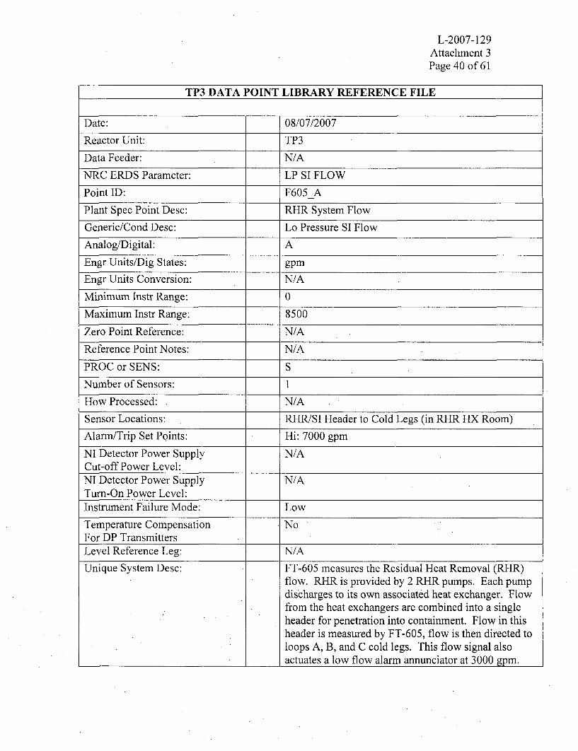
NRC ERDS Parameter: LP SI FLOW
Point ID: F605 A
Plant Spec Point Desc: RHR System Flow
Generic/Cond Desc: Lo Pressure SI Flow
Analog/Digital: A
Engr Units/Dig States: gpm
Engr Units Conversion: N/A
Minimum Instr Range: 0
Maximum Instr Range: 8500
Zero Point Reference: N/A
Reference Point Notes: N/A
PROC or SENS: S
Number of Sensors: 1
How Processed: N/A
Sensor Locations: RHR/SI Header to Cold Legs (in RHR HX Room)
Alarn-/Trip Set Points: Hi: 7000 gpm
NI Detector Power Supply N/ACut-off Power Level:NI Detector Power Supply N/ATurn-On Power Level:Instrument Failure Mode: Low
Temperature Compensation NoFor DP TransmittersLevel Reference Leg: N/A
Unique System Desc: FT-605 measures the Residual Heat Removal (RHR)flow. RHR is provided by 2 RHR pumps. Each pumpdischarges to its own associated heat exchanger. Flowfrom the heat exchangers are combined into a singleheader for penetration into containment. Flow in thisheader is measured by FT-605, flow is then directed toloops A, B, and C cold legs. This flow signal alsoactuates a low flow alarm annunciator at 3000 gpm.

L-2007-129Attachment 3Page 41 of 61
TP3 DATA POINT LIBRARY REFERENCE FILE
Date: 08/07/2007
Reactor Unit: TP3
Data Feeder: N/A
NRC ERDS Parameter: CTMNT SMP NR
Point ID: CHILVLL V
Plant Spec Point Desc: CNTMT LR Sump Water Level
Generic/Cond Desc: Containment Sump Lo-Range Level
Analog/Digital: A
Engr Units/Dig States: Inches
Engr Units Conversion: N/A
Minimum Instr Range: 0
Maximum Instr Range: 369
Zero Point Reference: -18' 8" El
Reference Point Notes: N/A
PROC or SENS: P
Number of Sensors: 2
How Processed: 2 Input Hi Select w/ 5% Deviation check
Sensor Locations: Containment Sump
Alarm/Trip Set Points: N/A
NI Detector Power Supply N/ACut-off Power Level:NI Detector Power Supply N/ATurn-On Power Level:Instrument Failure Mode: As-Is
Temperature Compensation N/AFor DP TransmittersLevel Reference Leg: N/A
Unique System Desc: Containment sump level is the highest of the two sumplevel channels. Each channel consists of 5 segment,float and reed switch level column. The level columnstarts at the -18'8" elevation (i.e., below sea level) andcovers 30'9" of level. The conversion from inches togallons is non-linear. Note: The elevation between 12'and 14'3" is not covered by the contaimnent sump orcontainment level transmitters.

L-2007-129Attachment 3Page 42 of 61
TP3 DATA POINT LIBRARY REFERENCE FILE
Date: 08/07/2007
Reactor Unit:. TP3
Data Feeder: N/A
NRC ERDS Parameter: CTMNT SMP WR
Point ID: CHILVLH V
Plant Spec Point Desc: CNTMT HR Water Level
Generic/Cond Desc: Containment Sump Hi-Range Level
Analog/Digital: A
Engr Units/Dig States: Inches
Engr Units Conversion: N/A
Minimum Instr Range: 397
Maximum Instr Range: 487.5
Zero Point Reference: N/A
Reference Point Notes: N/A
PROC or SENS: P
Number of Sensors: 2
How Processed: 2 Input Hi Select
Sensor Locations: Containment Floor 14' El & Above
Alarm/Trip Set Points: N/A
NI Detector Power Supply N/ACut-off Power Level:NI Detector Power Supply N/ATurn-On Power Level:Instrument Failure Mode: As-Is
Temperature Compensation N/AFor DP TransmittersLevel Reference Leg: N/A
Unique System Desc: Containmient level is the highest of the 2 containmentlevel channels. Each channel consists of a float andreed switch level column. The level. column starts atthe 14'3" elevation and covers 7'6" of level. Theconversion from inches to gallons is non-linear. Note:The elevation between 12' and 14'3" is not covered bythe containment sump or containment leveltransmitters.

L-2007-129Attachment 3Page 43 of 61
TP3 DATA POINT LIBRARY REFERENCE FILE
Date: 08/07/2007
Reactor Unit: TP3
Data Feeder: N/A
NRC ERDS Parameter: NL
Point ID: R14-A
Plant Spec Point Desc: Plant Vent Gas Activity
Generic/Cond Desc: Radioactivity Of A Released Gas
Analog/Digital: A
Engr Units/Dig States: cpm
Engr Units Conversion: N/A
Minimum Instr Range: 10
Maximum Instr Range: 1 E6
Zero Point Reference: N/A
Reference Point Notes: N/A
PROC or SENS: S
Number of Sensors: 1
How Processed: N/A
Sensor Locations: Top Of Plant Vent Stack
Alarm/Trip Set Points: Determined By Radiochemist
NI Detector Power Supply N/ACut-off Power Level:NI Detector Power Supply N/ATurn-On Power Level:Instrument Failure Mode: Low
Temperature Compensation N/AFor DP TransmittersLevel Reference Leg: N/A
Unique System Desc: R-14 is installed inside the plant vent. It consists of 4thin-walled Gieger-Mueller tube detectors arrangedacross the plant vent stack diameter. The 4 detectorsoperate in parallel, are Beta-Gamma sensitive in therange of 5E-7 to 1E-4 Ci/cc, and have a check source.R-14 alarm will automatically close the Gas DecayTank discharge valve upon actuation. Note: cpm touCi/cc conversion factor is 2E8 ml/cc at sample flowrate.

L-2007-129Attachment 3Page 44 of 61
TP3 DATA POINT LIBRARY REFERENCE FILE
Date: 08/07/2007
Reactor Unit: TP3
Data Feeder: N/A
NRC ERDS Parameter: EFF GAS RAD
Point ID: R6304HRA
Plant Spec Point Desc: Plant Vent Gas Gamma Hi Range
Generic/Cond Desc: Radioactivity Of Released Gases
Analog/Digital: A
Engr Units/Dig States: uCi/cc
Engr Units Conversion: N/A
Minimum Instr Range: 1.OE-1
Maximum Instr Range: L.0E5
Zero Point Reference: N/A
Reference Point Notes: N/A
PROC or SENS: P
Number of Sensors: I
How Processed: Data Link
Sensor Locations: Auxiliary Building
Alarm/Trip Set Points: N/A
NI Detector Power Supply N/ACut-off Power Level:NI Detector Power Supply N/ATurn-On Power Level:Instrument Failure Mode: As-Is
Temperature Compensation N/AFor DP TransmittersLevel Reference Leg: N/A
Unique System Desc: An Eberline SPING Unit provides Plant Vent HighRange Noble Gas Activity. The detector type is aGeiger-Mueller tube, uncompensated with a checksource. The plant vent stack is the normal dischargepath for: Unit 3 & 4 containment purge, auxiliarybuilding exhaust and Unit 4 SFP. Note: Unit 3 SFPexhaust is through a dedicated stack.

L-2007-129•Attaclunent 3Page 45 of 61
TP3 DATA POINT LIBRARY REFERENCE FILE
Date: 08/07/2007
Reactor Unit: TP3
Data Feeder: N/A
NRC ERDS Parameter: NL
Point ID: R6304FLO A
Plant Spec Point Desc: Plant Vent Flow Rate
Generic/Cond Desc: Plant Vent Stack Flow Rate
Analog/Digital: A
Engr Units/Dig States: cfm
Engr Units Conversion: N/A
Minimum Instr Range: 0
Maximum Instr Range: 1.5E+5
Zero Point Reference: N/A
Reference Point Notes: N/A
PROC or SENS: P
Number of Sensors: 1
How Processed: Data Link
Sensor Locations: Plant Vent Stack Near Top
Alarm/Trip Set Points: N/A
NI Detector Power Supply N/ACut-off Power Level:NI Detector Power Supply N/ATurn-On Power Level:Instrument Failure Mode: As-Is
Temperature Compensation N/AFor DP TransmittersLevel Reference Leg: N/A
Unique System Desc: Plant vent flow is provided by transmitter FT-6584which measures the differential pressure across a floworifice installed in the plant vent stack. The signal isprocessed by an optional analog to digital channel(#10) on the Plant Vent SPING unit. Note: Loss ofplant vent flow channel will not affect the calibrationof the plant vent high range gas monitor which is basedon a fixed sample flow rate.

L-2007-129Attachment 3Page 46 of 61
TP3 DATA POINT LIBRARY REFERENCE FILE
Date: 08/07/2007
Reactor Unit: TP3
Data Feeder: N/A
NRC ERDS Parameter: NL
Point ID: R6418HRAPlant Spec Point Desc: U3 Fuel Pool Gas Gamma Hi Rng
Generic/Cond Desc: Radioactivity Of Released Gases
Analog/Digital: A
Engr Units/Dig States: uCi/cc
Engr Units Conversion: N/A
Mininmm Instr Range: 1.0E-1
Maximum Instr Range: 1.0E+5
Zero Point Reference: N/A
Reference Point Notes: N/A
PROC or SENS: P
Number of Sensors: 1
How Processed: Data Link
Sensor Locations: U3 Spent Fuel Pool Vent Stack
Alarm/Trip Set Points: Determined By Radiochemist
NI Detector Power Supply N/ACut-off Power Level:NI Detector Power Supply N/ATurn-On Power Level:Instrument Failure Mode: As-Is
Temperature Compensation N/AFor DP TransmittersLevel Reference Leg: N/A
Unique System Desc: An Eberline SPING Unit provides the Unit 3 SpentFuel Pit High Range Noble Gas Activity. The detectortype is a Geiger-Mueller tube, uncompensated with acheck source. The Unit 3 spent fuel pit exhaust isthrough a dedicated stack. The flow rate is -18,500cfn when the exhaust fan is running. Note: Use pointFAN3V21 A as an indication of fan running.

L-2007-129Attaclhment 3Page 47 of 61
TP3 DATA POINT LIBRARY REFERENCE FILE
Date: 08/07/2007
Reactor Unit: TP3
Data Feeder: N/A
NRC ERDS Parameter: EFF LIQ RAD
Point ID: R18-A
Plant Spec Point Desc: Liquid Release Gross Activity
Generic/Cond Desc: Radioactivity Of Released Liquid
Analog/Digital: A
Engr Units/Dig States: cpm
Engr Units Conversion: N/A
Minimum Instr Range: 10
Maximum Instr Range: 1.0E+6
Zero Point Reference: N/A
Reference Point Notes: N/A
PROC or SENS: S
Number of Sensors: I
How Processed: N/A
Sensor Locations: Liquid Release Line In Aux Bldg
Alarm/Trip Set Points: Determined By Radiochemist
NI Detector Power Supply N/ACut-off Power Level:NI Detector Power Supply N/ATurn-On Power Level:Instrument Failure Mode: Low
Temperature Compensation N/AFor DP TransmittersLevel Reference Leg: N/A
Unique System Desc: R- 18 monitors liquid waste release activity in the wastedischarge header upstream of the liquid releaseisolation valve RCV-018. The detector is a sodiumiodide scintillation tube, lead shielded againstbackground. The alarm setpoint is plant conditiondependent and set by the Radiochemist. The liquidwaste control valve (RCV- 18) auto isolates on a highactivity alarm. Note: the cpm to uci/cc conversionfactor is 2.96E7 ml-cpm at 100 gpm.

L-2007-129Attachment 3Page 48 of 61
TP3 DATA POINT LIBRARY REFERENCE FILE
Date: 08/07/2007
Reactor Unit: TP3
Data Feeder: N/A
NRC ERDS Parameter: NL
Point ID: R15-A
Plant Spec Point Desc: Condenser Air Ejector (PRMS)
Generic/Cond Desc: Condenser Air Ejector Rad
Analog/Digital: A
Engr Units/Dig States: cpm
Engr Units Conversion: N/A
Minimum Instr Range: 10
Maximum Instr Range: 1.0E+6
Zero Point Reference: N/A
Reference Point Notes: N/A
PROC or. SENS: S
Number of Sensors: 1
How Processed: N/A
Sensor Locations: Turbine Deck
Alarm/Trip Set Points: Determined By Radiochemist
NI Detector Power Supply N/ACut-off Power Level:NI Detector Power Supply N/ATurn-On Power Level:Instrument Failure Mode: Low
Temperature Compensation . N/AFor DP TransmittersLevel Reference Leg:. N/A
Unique System Desc: R-15, the Condenser Air Ejector Monitor uses a thinwall Geiger-Mueller tube detector. The detector islocated in the air ejector exhaust manifold and useslead shielding against background. The alann setpointis plant condition dependent and is determined by theRadiochemist.

L-2007-129Attachment 3Page 49 of 61
TP3 DATA POINT LIBRARY REFERENCE FILE
Date: 08/07/2007
Reactor Unit: TP3
Data Feeder: N/A
NRC ERDS Parameter: COND A/E RAD
Point ID: R6417HR A
Plant Spec Point Desc: I Air Ejector Gas Gamma Hi-Rng
Generic/Cond Desc: Condenser Air Ejector Rad
Analog/Digital: A
Engr Units/Dig States: uCi/cc
Engr Units Conversion: N/A
Minimum Instr Range: 1.0E-1
Maximum Instr Range: 1.0E÷5
Zero Point Reference: N/A
Reference Point Notes: N/A
PROC or SENS: P
Number of Sensors: 1
How Processed: Data Link
Sensor Locations: Turbine Deck
Alarm/Trip Set Points: Determined By Radiochemist
NI Detector Power Supply N/ACut-off Power Level:NI Detector Power Supply N/ATurn-On Power Level:Instrument Failure Mode: As-Is
Temperature Compensation N/AFor DP TransmittersLevel Reference Leg: M/A
Unique System Desc: An Eberline SPING Unit provides the Air Ejector PlantVent Hi-Range Noble Gas Activity. The detector typeis a Gieger-Mueller tube, uncompensated with a checksource.

L-2007-129Attachment 3Page 50 of 61
TP3 DATA POINT LIBRARY REFERENCE FILE
Date: 08/07/2007
Reactor Unit: TP3
Data Feeder: N/A
NRC ERDS Parameter: CNTMT RAD
Point ID: CHRADW V
Plant Spec Point Desc: Containment Radiation (WR)
Generic/Cond Desc: Radiation Level In Containment
Analog/Digital: A
Engr Units/Dig States: R/Hr
Engr Units Conversion: N/A
Minimum Instr Range: 1.0
Maximum Instr Range: 1 .0E÷8
Zero Point Reference: N/A
Reference Point Notes:. N/A
PROC or SENS: P
Number of Sensors: 2
How Processed: 2 Input Hi Select w/ 5 % Deviation limit
Sensor Locations: Rx Bldg @ 25' & 64' El
Alarm/Trip Set Points: Hi: 1.3E4 R/Hr Hi-Hi: 1.3E5 R/Hr
NI Detector Power Supply N/ACut-off Power Level:NI Detector Power Supply N/ATurn-On Power Level:Instrument Failure Mode: As-Is
Temperature Compensation N/AFor DP TransmittersLevel Reference Leg: N/A
Unique System Desc: CNTMT RAD is the higher of 2 channel inputs(RAD631 IA and RAD631 11B). Both use ion chamberdetectors. RAD63 11A is located inside containment onthe 25' level near the personnel hatch and RAD631 1Bis near the 64' level on the SG shield wall near thepressurizer ARMS channel R-2. These channels have2 Hi Alarm setpoints, the first one activating anannunciator.

L-2007-129Attachment 3Page 51 of 61
TP3 DATA POINT LIBRARY REFERENCE FILE
Date: 08/07/2007
Reactor Unit: TP3
Data Feeder: N/A
NRC ERDS Parameter: RCS LTDN RAD
Point ID: R20-A
Plant Spec Point Desc: RCS Letdown Line Activity
Generic/Cond Desc: Rad Level Of The RCS Letdown
Analog/Digital: A
Engr Units/Dig States: mR/Hr
Engr Units Conversion: N/A
Minimum Instr Range: 1.0
Maximum Instr Range: 1.0E+5
Zero Point Reference: N/A
Reference Point Notes: N/A
PROC or SENS: S
Number of Sensors: I
How Processed: N/A
Sensor Locations: RCS letdown piping upstream of HX
Alarm/Trip Set Points: Hi 5.0E+4 mR/Hr
NI Detector Power Supply N/ACut-off Power Level:NI Detector Power Supply N/ATurn-On Power Level:Instrument Failure Mode: Low
Temperature Compensation N/AFor DP TransmittersLevel Reference Leg: N/A
Unique System Desc: R-20 provides reactor coolant letdown line activity.The monitor is located on the letdown line, outside ofcontainment and upstream of the non-regenerative heatexchanger. The monitor is external to the pipingsystem and far enough from the coolant loop that a 40second transient time is provided for N16 gammadecay. The detector is a Geiger-Mueller tube.

L-2007-129Attachment 3Page 52 of 61
TP3 DATA POINT LIBRARY REFERENCE FILE
Date: 08/07/2007
Reactor Unit: TP3
Data Feeder: N/A
NRC ERDS Parameter: N/L
Point ID: R6426_A
Plant Spec Point Desc: Main Stm Lines Gamma Hi Rng
Generic/Cond Desc: Main Steam Lines Radioactivity
Analog/Digital: A
Engr Units/Dig States: uCi/cc
Engr Units Conversion: N/A
Minimum Instr Range: 1.0E1
Maximum Instr Range: 1.0E+5
Zero Point Reference: N/A
Reference Point Notes: N/A
PROC or SENS: P
Number of Sensors: 1
How Processed: Data Link
Sensor Locations: Main Steam Sample lines
Alarm/Trip Set Points: Determined By Plant Radiochemist
NI Detector Power Supply N/ACut-off Power Level:NI Detector Power Supply N/ATurn-On Power Level:Instrument Failure Mode: As-Is
Temperature Compensation N/AFor DP TransmittersLevel Reference Leg: N/A
Unique System Desc: RAD6426-Main Steam Line High Range Gamma ismeasured by the Eberline DAM-1. Detector type is aGieger-Mueller Tube with no compensation. Note:sample lines from all 6 SGs run simultaneously throughthe detector. To identify a ruptured SG, manualisolation valves must be operated.

L-2007-129Attachment 3Page 53 of 61
TP3 DATA POINT LIBRARY REFERENCE FILE
Date: 08/07/2007
Reactor Unit: TP3
Data Feeder: N/A
NRC ERDS Parameter: NL
Point ID: R19-A
Plant Spec Point Desc: Stm Gen Liquid Sample Activity
Generic/Cond Desc: SG Blowdown Radioactivity
Analog/Digital: A
Engr Units/Dig States: cpm
Engr Units Conversion: N/A
Minimum Instr Range: 10
Maximum Instr Range: 1.0E+6
Zero Point Reference: N/A
Reference Point Notes: N/A
PROC or SENS: S
Number of Sensors: I
How Processed: N/A
Sensor Locations: Auxiliary Bldg N-S Hallway
Alarm/Trip Set Points: Determined By Radiochemist
NI Detector Power Supply N/ACut-off Power Level:NI Detector Power Supply N/ATurn-On Power Level:Instrument Failure Mode: 10
Temperature Compensation N/AFor DP TransmittersLevel Reference Leg: N/A
Unique System Desc: Detector type - Scintillation. Located in the combinedSG sample line. R-19 provides for auto closure of all 3(Unit 3) SG sample lines, all 3 blowdown flow controlvalves, and both (2) blowdown tank drain valves. HighAlarm setpoint is determined by Radiochemist based.on plant conditions.

L-2007-129Attachment 3Page 54 of 61
TP3 DATA POINT LIBRARY REFERENCE FILE
Date: 08/07/2007
Reactor Unit: TP3
Data Feeder: N/A
NRC ERDS Parameter: CTMNT PRESS
Point ID: CAVPRSW V
Plant Spec Point Desc: Containment Pressure (WR)
Generic/Cond Desc: Containment Pressure
Analog/Digital: A
Engr Units/Dig States: psig
Engr Units Conversion: N/A
Minimum Instr Range: 0
Maximum Instr Range: 180
Zero Point Reference: N/A
Reference Point Notes: N/A
PROC or SENS: P
Number of Sensors: 2
How Processed: 2 Input Average w/ 5 % Deviation check
Sensor Locations: South Penetration Room
Alarm/Trip Set Points: Hi: 20 psig Hi-Hi: 55 psig
NI Detector Power Supply N/ACut-off Power Level:NI Detector Power Supply N/ATurn-On Power Level:Instrument Failure Mode: As-Is
Temperature Compensation N/AFor DP TransmittersLevel Reference Leg: N/A
Unique System Desc: 5 % Deviation check meaning the value at which pointbecomes Poor Quality. Containment pressuretransmitters provide containment Hi and Hi-Hiactuation of the ESFAS circuitry at 4 psig and 20 psigrespectively. Hi containment pressure actuates SafetyInjection, while the Hi-Hi pressure coincident with theHi pressure will actuate containment sprays and PhaseB Containment Isolation.

L-2007-129Attachment 3Page 55 of 61
TP3 DATA POINT LIBRARY REFERENCE FILE
Date: 08/07/2007
Reactor Unit: TP3
Data Feeder: N/A
NRC ERDS Parameter: CTMNT TEMP
Point ID: CHITMP V
Plant Spec Point Desc: Containment Temperature
Generic/Cond Desc: Containment Temperature
Analog/Digital: A
Engr Units/Dig States: OF
Engr Units Conversion: N/A
Minimum Instr Range: 0
Maximum Instr Range: 300
Zero Point Reference: N/A
Reference Point Notes: N/A
PROC or SENS: P
Number of Sensors: 3
How Processed: 3 Input Hi Select
Sensor Locations: Containment El 58' @ 120' Intervals
Alarm/Trip Set Points: N/A
NI Detector Power Supply N/ACut-off Power Level:NI Detector Power Supply N/ATurn-On Power Level:Instrument Failure Mode: As-Is
Temperature Compensation N/AFor DP TransmittersLevel Reference Leg: N/A
Unique System Desc: The containment temperature is the average of 3channels (TE6700, TE6701, and TE6702). Eachchannel uses platinum RTD. TE6700 is located nearthe 3B Normal Containment Cooler, TE6701 is locatednear the 3C Normal Containment Cooler, TE6702 islocated near the 3C Emergency Containment Filters.CHITMPV provides an input to DEGCNTMT_Valarm @ 140 OF.

L-2007-129Attachnent 3Page 56 of 61
TP3 DATA POINT LIBRARY REFERENCE FILE
Date: 08/07/2007
Reactor Unit: TP3
Data Feeder: N/A
NRC ERDS Parameter: H2 CONC
Point ID: CH2CONCV
Plant Spec Point Desc: CTMT Hydrogen Concentration
Generic/Cond Desc: Containment Atmosphere H2 Conc
Analog/Digital: A
Engr Units/Dig States: % H2
Engr Units Conversion: N/A
Minimum Instr Range: 0
Maximum Instr Range: 10
Zero Point Reference: N/A
Reference Point Notes: N/A
PROC or SENS: P
Number of Sensors: 2
How Processed: 2 Input Hi Select w/ 5 % Deviation check
Sensor Locations: Aux Bldg Basement
Alarm/Trip Set Points: 4%
NI Detector Power Supply N/ACut-off Power Level:NI Detector Power Supply N/ATurn-On Power Level:Instrument Failure Mode: AS-IS
Temperature Compensation N/AFor DP TransmittersLevel Reference Leg: N/A
Unique System Desc: Two channels of instrumentation are provided, thehighest which is reported. A % H2 signal is developedby comparing the thermal conductivity of a referencesample with the conductivity of a sample afterremoving any nitrogen. The system provides a high H2
annunciator alarm at 7.5%, Low and Hi Cell Failure,Calibration Gas Low Pressure, Reagent Gas LowPressure, and Low Analyzer Flow Alarm.

L-2007-129Attachment 3Page 57 of 61
TP3 DATA POINT LIBRARY REFERENCE FILE
Date: 08/07/2007
Reactor Unit: TP3
Data Feeder: N/A
NRC ERDS Parameter: RWST LEVEL
Point ID: RWSTAVL V
Plant Spec Point Desc: RWST (Unit 3) Average Level
Generic/Cond Desc: Borated Water Storage Tank Level
Analog/Digital: A
Engr Units/Dig States: gal
Engr Units Conversion: N/A
Minimum Instr Range: 0
Maximum Instr Range: 335,000 gals
Zero Point Reference: TNKBOT
Reference Point Notes: N/A
PROC or SENS: P
Number of Sensors: 2
How Processed: 2 Input Average w/ 5 % Deviation check
Sensor Locations: Ground Level by RWST
Alarm/Trip Set Points: See Description
NI Detector Power Supply N/ACut-off Power Level:NI Detector Power Supply N/ATurn-On Power Level:Instrument Failure Mode: AS-IS
Temperature Compensation N/AFor DP TransmittersLevel Reference Leg: DRY
Unique System Desc: 5 % Deviation check meaning the value at which pointbecomes Poor Quality. Each RWST level loop consistsof a Rosemount DP transmitter and Foxboro Modulesto provide alarm and indication functions. Alarmsprovided are: Lo-Lo Level at 60,000 gallons, LowLevel at 155,000 gallons, Tech Spec Min Level at322,000 gallons and Hi Level at 333,000 gallons.Note: the RWST is the Borated Water Storage Tank.

L-2007-129Attachment 3Page 58 of 61
TP3 DATA POINT LIBRARY REFERENCE FILE
Date: 08/07/2007
Reactor Unit: TP3
Data Feeder: N/A
NRC ERDS Parameter: WIND SPEED
Point ID: WS10M LUA
Plant Spec Point Desc: 10 Meter Wind Speed (T.P.)
Generic/Cond Desc: Wind Speed At Reactor Site
Analog/Digital: A
Engr Units/Dig States: mph
Engr Units Conversion: N/A
Minimum Instr Range: 0
Maximum Instr Range: 100
Zero Point Reference: N/A
Reference Point Notes: N/A
PROC or SENS: S
Number of Sensors: 1
How Processed: N/A
Sensor Locations: 10 Meter Tower 1 Mile SW of Plant
Alarm/Trip Set Points: Hi: 75 mph Hi-Hi: 90 mph
NI Detector Power Supply N/ACut-off Power Level:NI Detector Power Supply N/ATurn-On Power Level:Instrument Failure Mode: 0
Temperature Compensation N/AFor DP TransmittersLevel Reference Leg: N/A
Unique System Desc: Wind Speed meteorological data is gathered by',instruments mounted on a 10 meter tower. The data (a15 minute runming average) is transmitted by radio tothe plant and is received by the Campbell Scientificequipment located in the Plant Computer Room.

L-2007-129Attachment 3Page 59 of 61
TP3 DATA POINT LIBRARY REFERENCE FILE
Date: 08/07/2007
Reactor Unit: TP3
Data Feeder: N/A
NRC ERDS Parameter: WIND DIR
Point ID: WD1OMLUA
Plant Spec Point Desc: 10 Meter Wind Direction (T.P.)
Generic/Cond Desc: Wind Direction At Reactor Site
Analog/Digital: A
Engr Units/Dig States: 0 (Degrees)
Engr Units Conversion: N/A
Minimum Instr Range: 0
Maximum Instr Range: 540
Zero Point Reference: N/A
Reference Point Notes: 0 And 360 Are North. Switch Pt 180
PROC or SENS: S
Number of Sensors: 1
How Processed: N/A
Sensor Locations: 10 Meter Tower 1 Mile Sw Of Plant
Alarm/Trip Set Points: N/A
NI Detector Power Supply N/ACut-off Power Level:NI Detector Power Supply N/ATurn-On Power Level:Instrument Failure Mode: 0
Temperature Compensation N/AFor DP TransmittersLevel Reference Leg: N/A
Unique System Desc: Wind direction is provided by instruments mounted ona 10 meter tower. The data (a 15 minute runningaverage) is transmitted by radio to the plant and isreceived by the Campbell Scientific equipment locatedin the Computer Room. The 10 Meter Tower is located1 mile SW of the site. Note: Wind is coming fromdirection reported by the instrument, with 0 and 360being North.

L-2007-129Attachment 3Page 60 of 61
TP3 DATA POINT LIBRARY REFERENCE FILE
Date: 08/07/2007
Reactor Unit: TP3
Data Feeder: N/A
NRC ERDS Parameter: STABB CLASS
Point ID: STABBSDA
Plant Spec Point Desc: Estimate Of Atmos Stability
Generic/Cond Desc: Air Stability At A Reactor Site
Analog/Digital: A
Engr Units/Dig States: df/mm
Engr Units Conversion: N/A
Minimum Instr Range: -5
Maximum Instr Range: 15
Zero Point Reference: N/A
Reference Point Notes: N/A
PROC or SENS: S
Number of Sensors: 1
How Processed: N/A
Sensor Locations: 60 Meter Tower 7 Miles SSW Of Plant
Alarm/Trip Set Points: N/A
NI Detector Power Supply N/ACut-off Power Level:NI Detector Power Supply N/ATurn-On Power Level:Instrument Failure Mode: -5
Temperature Compensation N/AFor DP TransmittersLevel Reference Leg: N/A
Unique System Desc: Atmospheric stability is developed by taking thedifference between the temperature at the 10 meter and60 meters. The difference is multiplied by 2 to obtainthe change per 100 meters altitude. A 15 minuterunning average data transmitted by radio telemetry toa Campbell Scientific receiver in the Plant ComputerRoom.
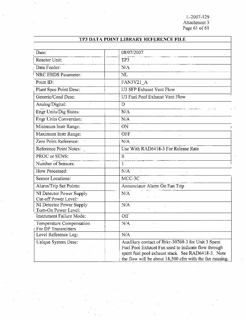
L-2007-129Attachment 3Page 61 of 61
TP3 DATA POINT LIBRARY REFERENCE FILE
Date: 08/07/2007
Reactor Unit: TP3
Data Feeder: N/A
NRC ERDS Parameter: NL
Point ID: FAN3V21A
Plant Spec Point Desc: U3 SFP Exhaust Vent Flow
Generic/Cond Desc: U3 Fuel Pool Exhaust Vent Flow
Analog/Digital: D
Engr Units/Dig States: N/A
Engr Units Conversion: N/A
Minimum Instr Range: ON
Maximum Instr Range: OFF
Zero Point Reference: N/A
Reference Point Notes: . Use With RAD6418-3 For Release Rate
PROC or SENS: S
Number of Sensors: 1
How Processed: N/A
Sensor Locations: MCC-3C
Alarm/Trip Set Points: Annunciator Alarm On Fan Trip
NI Detector Power Supply N/ACut-off Power Level:NI Detector Power Supply N/ATurn-On Power Level:Instrument Failure Mode: Off
Temperature Compensation N/AFor DP TransmittersLevel Reference Leg: N/A.
Unique System Desc: Auxiliary contact of Brkr-30769-3 for Unit 3 SpentFuel Pool Exhaust Fan used to indicate flow throughspent fuel pool exhaust stack. See RAD6418-3. Notethe flow will be about 18,500 cfm with the fan running.

ATTACHMENT 4
. APPENDIX C
TURKEY POINT UNIT 4
ERDS DATA POINT LIBRARY

L-2007-129Attachment 4Page 1 of 59
TP4 DATA POINT LIBRARY REFERENCE FILE
Date: 08/07/2007
Reactor Unit: TP4
Data Feeder: N/A
NRC ERDS Parameter: NI Power Rng
Point ID: NIAVPRLVL-4
Plant Spec Point Desc: Power Range Power Level
Generic/Cond Desc: Nuclear Instr, Power Range
Analog/Digital: A
Engr Units/Dig States: %
Engr Units Conversion: N/A
Minimum Instr Range: 0
Maximum Instr Range; 120
Zero Point Reference: N/A
Reference Point Notes: N/A
PROC or SENS: P
Number of Sensors: 4
How Processed: 4 Input Average, w/3 % Deviation Limit
Sensor Locations: RX Vessel @ 45, 135, 225, & 315 degrees, 14'El
Alarm/Trip Set Points: Hi: 103% Hi-Hi Rx Trip: 108%
NI Detector Power Supply N/ACut-off Power Level:NI Detector Power Supply N/ATurn-On Power Level:Instrument Failure Mode: As-Is
Temperature Compensation N/AFor DP TransmittersLevel Reference Leg: N/A
Unique System Desc: 3% deviation being the limit for use in calculation andQuality determination. The detector type is an excoredual ion chamber (upper-lower arrangement). Hi 103%(Rod Stop) Hi Hi 108% (RX Trip). This instrumentalso inputs a 2/4 logic for a Low Power - Hi Flux RxTrip signal at 25% power.

L-2007-129Attachment 4Page 2 of 59
TP4 DATA POINT LIBRARY REFERENCE FILE
Date: 08/07/2007
Reactor Unit: TP4
Data Feeder: N/A
NRC ERDS Parameter: NI Inter Rng
Point ID: NIAVIRLVL-4
Plant Spec Point Desc: Intermediate Range Power Level
Generic/Cond Desc: Nuclear Instr, Intermediate Range
Analog/Digital: A
Engr Units/Dig States: Amps
Engr Units Conversion: N/A
Minimum Instr Range: 1.0E 11
Maximum Instr Range: 1.0E 3
Zero Point Reference: N/A
Reference Point Notes: N/A
PROC or SENS: P
Number of Sensors: 2
How Processed: 2 Input Average w/ 5 % Deviation check
Sensor Locations: Rx Vessel @ 90 & 270 Deg. 14' El
Alarm/Trip Set Points: P6: 1.001 E -10 Amps
NI Detector Power Supply N/ACut-off Power Level:NI Detector Power Supply <1.0E -10 AmpsTurn-On Power Level:Instrument Failure Mode: As-Is
Temperature Compensation N/AFor DP TransmittersLevel Reference Leg: N/A
Unique System Desc: 5 % Deviation check meaning the value at which pointbecomes Poor quality. The average is determined fromN35_A and N36_A intermediate range channel signals.The detectors are compensated ion chambers located atthe core. The P6 setpoint is 1.001 E 10 Amps. Thisinstrument also inputs a 1/2 logic Low Power Rx tripsignal at 1.2 E -4 amps (equiv to 25% power).

L-2007-129Attachment 4Page 3 of 59
TP4 DATA POINT LIBRARY REFERENCE FILE
Date: 08/07/2007
Reactor Unit: TP4
Data Feeder: N/A
NRC ERDS Parameter: NI Source Rng
Point ID: NIAVSRLVL-4
Plant Spec Point Desc: Source Range Power Level,
Generic/Cond Desc:. Nuclear Instr, Source Range
Analog/Digital: A
Engr Units/Dig States: cps
Engr Units Conversion: N/A
Minimum Instr Range: 1.0E +0
Maximum Instr Range: 1.0E +6
Zero Point Reference: N/A
Reference Point Notes: N/A
PROC or SENS: P
Number of Sensors: 2
How Processed: 2 Input Average w/ 5 % Deviation check
Sensor Locations: Rx Vessel @ 90 & 270 Deg. 14' El.
Alann/Trip Set Points: Rx Trip at 1.0E5 cps
NI Detector Power Supply >1.0E4 cps (P6 Permissive)Cut-off Power Level:NI Detector Power Supply N/ATurn-On Power Level:Instrument Failure Mode: As-Is
Temperature Compensation N/AFor DP TransmittersLevel Reference Leg: N/A
Unique System Desc: 5 % Deviation check meaning the value at which pointbecomes Poor Quality. The average is determined fromN31 _A and N32 A source range channel signals. Thedetectors are in the lower half of detector wells sharedwith the intermediate range detectors.

L-2007-129Attachment 4Page 4 of 59
TP4 DATA POINT LIBRARY REFERENCE FILE
Date: 08/07/2007
Reactor Unit: TP4
Data Feeder: N/A
NRC ERDS Parameter: NL
Point ID: NI649AVPR-4
Plant Spec Point Desc: Gammametrics PR Avg
Generic/Cond Desc: Nuclear Instruments, Power Rng
Analog/Digital: A
Engr Units/Dig States: %
Engr Units Conversion: N/A
Minimum Instr Range: 1.OE 8
Maximum Instr Range: 200
Zero Point Reference: N/A
Reference Point Notes: N/A
PROC or SENS: P2
Numberof Sensors: 2
How Processed: 2 Input Average w/ 5 % Deviation check
Sensor Locations: RX Vessel @ 0 and 180 Deg. 14' El
Alarm/Trip Set Points: N/A
NI Detector Power Supply N/ACut-off Power Level:NI Detector Power Supply N/ATurn-On Power Level:Instrument Failure Mode: As-Is
Temperature Compensation N/AFor DP TransmittersLevel Reference Leg: N/A
Unique System Desc: 5 % Deviation check meaning the value at which pointbecomes Poor Quality. The Gammametrics SourceRange Detectors are located in the same wells as theGammametrics Power Range Detectors.

L-2007-129Attachment 4Page 5 of 59
TP4 DATA POINT LIBRARY REFERENCE FILE
Date: 08/07/2007
Reactor Unit: TP4
Data Feeder: N/A
NRC ERDS Parameter: NL
Point ID: NI649AVSR-4
Plant Spec Point Desc: Gammametrics SR Avg
Generic/Cond Desc: Nuclear Instruments, Source Rng
Analog/Digital: A
Engr Units/Dig States: cps
Engr Units Conversion: N/A
Minimum Instr Range: 1.OE 1
Maximum Instr Range: L.OE +5
Zero Point Reference: N/A
Reference Point Notes: N/A
PROC or SENS: P
Number of Sensors: 2
How Processed: 2 Input Average w/5 .% Deviation check
Sensor Locations: RX Vessel @ 0 and 180 Deg. 14' El
Alarm/Trip Set Points: N/A
NI Detector Power Supply N/ACut-off Power Level:NI Detector Power Supply N/ATurn-On Power Level:
Instrument Failure Mode: As-Is
Temperature Compensation N/AFor DP TransmittersLevel Reference Leg: N/A
Unique System Desc: 5 % Deviation check meaning the value at which pointbecomes Poor Quality. The Gammarnetrics SourceRange Detectors are located in the same detector wellsas the Gammarnetrics Power Range Detectors.

L-2007-129Attachment 4Page 6 of 59
TP4 DATA POINT LIBRARY REFERENCE FILE
Date: 08/07/2007
Reactor Unit: TP4
Data Feeder: N/A
NRC ERDS Parameter: Reac Ves Lev
Point ID: RXHDLVLLO-4
Plant Spec Point Desc: Reactor Upper Head Level
Generic/Cond Desc: Reactor Vessel Water Level
Analog/Digital: A
Engr Units/Dig States: %
Engr Units Conversion: N/A
Minimum Instr Range: 0
Maximum Instr Range: 100
Zero Point Reference: TAF
Reference Point Notes: N/A
PROC or SENS: P
Number of Sensors: 2
How Processed: 2 Input Low Select
Sensor Locations: RX Vessel - Upper Head
Alarm/Trip Set Points: Lo-Lo: 99.99%
NI Detector Power Supply N/ACut-off Power Level:NI Detector Power Supply N/ATurn-On Power Level:Instrument Failure Mode: As-Is
Temperature Compensation N/AFor DP TransmittersLevel Reference Leg: N/A
Unique System Desc: Reactor head water level indication consists of thelower of 2 QSPDS Trains of the top 2 sensors (1 & 2)of an eight sensor probe. Each sensor consists of aheated and an unheated thermocouple pair. The probeextends from the top of the head to the top of the fuelalignment plate. Sensor 1 is at 179" (33% indicated)above the fuel and sensor 2 is 142" (0% indicated).

L-2007-129Attachment 4Page 7 of 59
TP4 DATA POINT LIBRARY REFERENCE FILE
Date• 08/07/2007
Reactor Unit: TP4
Data Feeder: N/A
NRC ERDS Parameter: NL
Point ID: RXPLLVLLO-4
Plant Spec Point Desc: Reactor Plenum Water Level
Generic/Cond Desc: Reactor Vessel Plenum Water Level
Analog/Digital: A
Engr Units/Dig States: %
Engr Units Conversion: N/A
Minimum Instr Range: 0
Maximum Instr Range: 100
Zero Point Reference: TAF
Reference Point Notes: N/A
PROC or SENS: . P
Number of Sensors: 2
How Processed: 2 Input Low Select
Sensor Locations: Rx Vessel-Plenum Above Core
Alarm/Trip Set Points: N/A
NI Detector Power Supply N/ACut-off Power Level:NI Detector Power Supply. N/ATurn-On Power Level:Instrument Failure Mode: As-Is
Temperature Compensation N/AFor DP TransmittersLevel Reference Leg: N/A
Unique System Desc: Reactor plenum water level indication consists of thelower of 2 QSPDS Trains of the lower 6 sensors (3-8)of an eightsensor probe. Each sensor consists of aheated and an unheated thermocouple pair. Sensorlocations above the fuel from top to bottom (i.e.,sensors 3-8) are 128", 98", 69", 55", 40", and 24"respectively. Indicated levels are 81%, 58%, 40%,28%, 16%, and 0% respectively.

L-2007-129Attachment 4Page 8 of 59
TP4 DATA POINT LIBRARY REFERENCE FILE
Date: 08/07/2007
Reactor Unit: TP4
Data Feeder: N/A
NRC ERDS Parameter: Temp Core Ex
Point ID: CET-4
Plant Spec Point Desc: Core Exit Temperature
Generic/Cond Desc: Highest Temp At Core Exit
Analog/Digital: A
Engr Units/Dig States: OF
Engr Units Conversion: N/A
Minimum Instr Range: 0
Maximum Instr Range: 2300
Zero Point Reference: N/A
Reference Point Notes: N/A
PROC or SENS: P
Number of Sensors: 2
How Processed: 2 Input Hi Select
Sensor Locations: Inside Reactor Vessel-Core Exit Area
Alarrmi/Trip Set Points: Lo: 540'F Hi: 650'F
NI Detector Power Supply N/ACut-off Power Level:NI Detector Power Supply N/ATurn-On Power Level:Instrument Failure Mode: As-Is
Temperature Compensation N/AFor DP TransmittersLevel Reference Leg: N/A
Unique System Desc: Signals originate from 2 QSPDS (Qualified SafetyParameter Display System) Channel Trains selectingthe higher of 2 calculated representative core exitthermocouple (CET) temperatures. The representativeCET temperature is the average of the highest eightvalid CETs for that Train.

L-2007-129Attachment 4Page 9 of 59
TP4 DATA POINT LIBRARY REFERENCE FILE
Date: 08/07/2007
Reactor Unit: TP4
Data Feeder: N/A
NRC ERDS Parameter: Sub Margin
Point ID: SMM 1LO-4
Plant Spec Point Desc: Subcooling
Generic/Cond Desc: Sat Temp - Highest CET
Analog/Digital: A
Engr Units/Dig States: OF
Engr Units Conversion: N/A
Minimum Instr Range: - 2100
Maximum Instr Range: 700
Zero Point Reference: N/A
Reference Point Notes: N/A
PROC or SENS: P
Number of Sensors: 2
How Processed: 2 Input Low.Select
Sensor Locations: Core Exit Channels
Alarm/Trip Set Points: N/A
NI Detector Power Supply N/ACut-off Power Level:NI Detector Power Supply N/ATurn-On Power Level:Instrument Failure Mode: As-Is
Temperature Compensation N/AFor DP TransmittersLevel Reference Leg: N/A
Unique System Desc: Signals originate from 2 QSPDS (Qualified SafetyParameter Display System) Channel Trains selectingthe lower of 2 calculated subcooled margins. TheQSPDS subcooled margin calculation for each Trainuses a Hi-select RCS loop temperature input asmeasured against saturation temperature for existingRCS pressure.

L-2007-129Attachment 4Page 10 of 59
TP4 DATA POINT LIBRARY REFERENCE FILE
Date: 08/07/2007
Reactor Unit: TP4
Data Feeder: N/A
NRC ERDS Parameter: NL
Point ID: RCSA-AVFLO-4
Plant Spec Point Desc: RCS A Average Flow
Generic/Cond Desc: RCS Loop A Coolant Flow
Analog/Digital: A
Engr Units/Dig States: %
Engr Units Conversion: 1% = 895 GPM
Minimum Instr Range: 0
Maximum Instr Range: 120
Zero Point Reference: N/A.
Reference Point Notes: N/A
PROC or SENS: P
Number of Sensors: 3
How Processed: 3 Input Average w/6 % Deviation Limit
Sensor Locations: RCS Lower Loop Piping
Alanm/Trip Set Points: Lo: 104% LoLo Rx Trip: 90%
NI Detector Power Supply N/ACut-off Power Level:NI Detector Power Supply N/ATurn-On Power Level:Instrument Failure Mode: As-Is
Temperature Compensation NoFor DP TransmittersLevel Reference Leg: N/A
Unique System Desc: 6% deviation (5370 gpm) being the limit for use inaveraging calculation and for Quality determination.The flow is based on a differential pressure developedby a flow elbow located in the main coolant loop.100% flow: - 89,500 GPM. Lo RCS Flow Rx Trip at-90%. Minimum DNB flow: 104%.

L-2007-129Attachment 4Page 11 of 59
TP4 DATA POINT LIBRARY REFERENCE FILE
Date: 08/07/2007
Reactor Unit: TP4
Data Feeder: N/A
NRC ERDS Parameter: NL
Point ID: RCSB-AVFLO-4
Plant Spec Point Desc: RCS B Average Flow
Generic/Cond Desc: RCS Loop B Coolant Flow
Analog/Digital: A
Engr Units/Dig States: %
Engr Units Conversion: 1% = 895 GPM
Minimum Instr Range: 0
Maximum Instr Range: 120
Zero Point Reference: N/A
Reference Point Notes: N/A
PROC or SENS: P
Number of Sensors: 3
How Processed: 3 Input Average w/6 % Deviation Limit
SensorLocations: RCS Lower Loop Piping
Alarm/Trip Set Points: Lo: 104% LoLo Rx Trip: 90%
NI Detector Power Supply N/ACut-off Power Level:NI Detector Power Supply N/ATurn-On Power Level:Instrument Failure Mode: As-Is
Temperature Compensation NOFor DP TransmittersLevel Reference Leg: N/A
Unique System Desc: 6% deviation (5370 gpm) being the limit for use inaveraging calculation and for Quality determination.The flow is based on a differential pressure developedby a flow elbow located in the main coolant loop.100% flow: - 89,500 GPM. Lo RCS Flow Rx Trip at-90%. Minimum DNB flow: 104%.

L-2007-129Attachment 4Page 12 of 59
TP4 DATA POINT LIBRARY REFERENCE FILE
Date: 08/07/2007
Reactor Unit: TP4
Data Feeder: N/A
NRC ERDS Parameter: NL
Point ID: RCSC-AVFLO-4
Plant Spec Point Desc: RCS C Average Flow
Generic/Cond Desc: RCS Loop C Coolant Flow
Analog/Digital: A
Engr Units/Dig States: %
Engr Units Conversion: 1% = 895 GPM
Minimum Instr Range: 0
Maximum Instr Range: 120
Zero Point Reference: N/A
Reference Point Notes: N/A
PROC or SENS: P
Number of Sensors: 3
How Processed: 3 Input Average w/6 % Deviation Limit
Sensor Locations: RCS Lower Loop Piping
Alarm/Trip Set Points: Lo: 104% LoLo Rx Trip: 90%
NI Detector Power Supply N/ACut-off Power Level:NI Detector Power Supply N/ATurn-On Power Level:Instrument Failure Mode: As-Is
Temperature Compensation NOFor DP TransmittersLevel Reference Leg: N/A
Unique System Desc: 6% deviation (5370 gpm) being the limit for use inaveraging calculation and for Quality determination.The flow is based on a differential pressure developedby a flow elbow located in the main coolant loop.100% flow: - 89,500 GPM. Lo RCS Flow Rx Trip at-90%. Minimum DNB flow: 104%.

L-2007-129Attachment 4Page 13 of 59
TP4 DATA POINT LIBRARY REFERENCE FILE
Date: 08/07/2007
Reactor Unit: TP4
Data Feeder: N/A
NRC ERDS Parameter: SG LEVEL I/A
Point ID: SGA-AVLVL-4
Plant Spec Point Desc: Steam Generator Level A
Generic/Cond Desc: Steam Generator A Water Level
Analog/Digital: A
Engr Units/Dig States: %
Engr Units Conversion: 1% = 112.5 gallons
Minimum Instr Range: 0
Maximum Instr Range: 100
Zero Point Reference: U-Tubes
Reference Point Notes: N/A
PROC or SENS: P
Number of Sensors: 3
How Processed: 3 Input Average w/10% Deviation Limit
Sensor Locations: SG Vessel A 30' 6" EL
Alarm/Trip Set Points: Lo-Lo Rx Trip: 10% Lo: 35% Hi 68% Hi-Hi: 80%
NI Detector Power Supply N/ACut-off Power Level:NI Detector Power Supply N/ATurn-On Power Level:Instrument Failure Mode: As-Is
Temperature Compensation NOFor DP TransmittersLevel Reference Leg: WET
Unique System Desc: 10 % deviation being the limit for use in calculationand quality determination.0% = 16,250 gal100% = 27,500 galThe lower tap is 8" above the top of the tube bundle.Protection Train: 10 % Reactor Trip, 80 % TurbineTrip

L-2007-129Attachment 4Page 14 of 59
TP4 DATA POINT LIBRARY REFERENCE FILE
Date: 08/07/2007
Reactor Unit: TP4
Data Feeder: N/A
NRC ERDS Parameter: NL
Point ID: LT477-4
Plant Spec Point Desc: Steam Generator A Wide Rng Level
Generic/Cond Desc: Steam Generator A WR Water Level
Analog/Digital: A
Engr Units/Dig States: %
Engr Units Conversion: See Description
Minimum Instr Range: 0
Maximum Instr Range: 100
Zero Point Reference: Tubesheet
Reference Point Notes: N/A
PROC or SENS: S
Number of Sensors: 1
How Processed: N/A
Sensor Locations: Containment 30' 6" El
Alarm/Trip Set Points: Lo: 40% Hi: 93%
NI Detector Power Supply N/ACut-off Power Level:NI Detector Power Supply. N/ATurn-On Power Level:Instrument Failure Mode: Low
Temperature Compensation NoFor DP TransmittersLevel Reference Leg: WET
Unique System Desc: 0% = 750 gal100% = 27,500 galPercent to gal conversion is:
0-52 %: 187gal/%52-73 %: 274 gal / %
73-100 %: 417 gal/%

L-2007-129Attachmrent 4Page 15 of 59
TP4 DATA POINT LIBRARY REFERENCE FILE
Date: 08/07/2007
Reactor Unit: TP4
Data Feeder: N/A
NRC ERDS Parameter: SG LEVEL 2/B
Point ID: SGB-AVLVL-4
Plant Spec Point Desc: Steam Generator Level B
Generic/Cond Desc: Steam Generator B Water Level
Analog/Digital: A
Engr Units/Dig States: %
Engr Units Conversion: 1% = 112.5 gallons
Minimum Instr Range: 0
Maximum Instr Range: 100
Zero Point Reference: U-Tubes
Reference Point Notes: N/A
PROC or SENS: P
Number of Sensors: 3
How Processed: 3 Input Average w/10% Deviation Limit
Sensor Locations: SG Vessel B 30' 6" EL
Alarm/Trip Set Points: Lo-Lo Rx Trip: 10% Lo: 35% Hi 68% Hi-Hi: 80%
NI Detector Power Supply N/ACut-off Power Level:NI Detector Power Supply N/ATurn-On Power Level:Instrument Failure Mode: As-Is
Temperature Compensation NoFor DP TransmittersLevel Reference Leg: Wet
Unique System Desc: 10 % deviation being the limit for use in calculationand quality determination.0% = 16,250 gal100% = 27,500 galThe lower tap is 8" above the top of the tube bundle.Protection Train: 10 % Reactor Trip, 80 % TurbineTrip.

L-2007-129Attachment 4Page 16 of 59
TP4 DATA POINT LIBRARY REFERENCE FILE
Date: 08/07/2007
Reactor Unit: TP4
Data Feeder: N/A
NRC ERDS Parameter: NL
Point ID: LT487-4
Plant Spec Point Desc: Steam Generator B Wide Rng Level
Generic/Cond Desc: Steam Generator B WR Water Level
Analog/Digital: A
Engr Units/Dig States: %
Engr Units Conversion: See Description
Minimum Instr Range: 0
Maximum Instr Range: 100.
Zero Point Reference: Tubesheet
Reference Point Notes: N/A
PROC or SENS: S
Number of Sensors: 1
How Processed: N/A
Sensor Locations: Containment 30' 6" El
Alarm/Trip Set Points: Lo: 40% Hi: 93%
NI Detector Power Supply N/ACut-off Power Level:NI Detector Power Supply N/ATurn-On Power Level:Instrument Failure Mode: Low
Temperature Compensation NoFor DP TransmittersLevel Reference Leg: WET
Unique System Desc: 0% = 750 gal100% = 27,500 galPercent to gal conversion is:
0-52 %: 187gal/%52-73 %: 274 gal / %
73-100 %: 417 gal/%

L-2007-129Attaclhnent 4Page 17 of 59
TP4 DATA POINT LIBRARY REFERENCE FILE
Date: 08/07/2007
Reactor Unit: TP4
Data Feeder: N/A
NRC ERDS Parameter: SG LEVEL 3/C
Point ID: SGC-AVLVL-4
Plant Spec Point Desc: Steam Generator Level C
Generic/Cond Desc: Steam Generator C Water Level
Analog/Digital: A
Engr Units/Dig States: %
Engr Units Conversion: 1% = 112.5 gallons
Minimum Instr Range: 0
Maximum Instr Range: 100
Zero Point Reference: U-Tubes
Reference Point Notes: N/A
PROC or SENS: P
Number of Sensors: 3
How Processed: 3 Input Average w/10% Deviation Limit
Sensor Locations: SG Vessel C 30' 6" EL
Alarm/Trip Set Points: Lo-Lo Rx Trip: 10% Lo: 35% Hi 68% Hi-Hi: 80%
NI Detector Power Supply N/ACut-off Power Level:NI Detector Power Supply N/ATurn-On Power Level:Instrument Failure Mode: As-Is
Temperature Compensation NoFor DP TransmittersLevel Reference Leg: Wet
Unique System Desc: 10 % deviation being the limit for use in calculationand quality determination.0% = 16,250 gal100% = 27,500 galThe lower tap is 8" above the top of the tube bundle.Protection Train: 10 % Reactor Trip, 80 % Turbine
I Trip.

L-2007-129Attachment 4Page 18 of 59
TP4 DATA POINT LIBRARY REFERENCE FILE
Date: 08/07/2007
Reactor Unit: TP4
Data Feeder: N/A
NRC ERDS Parameter: NL
Point ID: LT497-4
Plant Spec Point Desc: Steam Generator C Wide Rng Level
Generic/Cond Desc: Steam Generator C WR Water Level
Analog/Digital: A
Engr Units/Dig States: %
Engr Units Conversion: See Description
Minimum Instr Range: 0
Maximum Instr Range: 100
Zero Point Reference: Tubesheet
Reference Point Notes: N/A
PROCor SENS: S
Number of Sensors: 1
How Processed: N/A
Sensor Locations: Containment 30' 6" El
Alarm/Trip Set Points: Lo: 40% Hi: 93%
NI Detector Power Supply N/ACut-off Power Level:NI Detector Power Supply N/ATurn-On Power Level:Instrument Failure Mode: Low
Temperature Compensation NoFor DP TransmittersLevel Reference Leg: WET
Unique System Desc: 0% = 750 gal100% = 27,500 galPercent to gal conversion is:
0-52 %: 187gal/%52-73 %: 274 gal / %
73-100 %: 417 gal/%

L-2007-129Attachment 4Page 19 of 59
TP4 DATA POINT LIBRARY REFERENCE FILE
Date: 08/07/2007
Reactor Unit: TP4
Data Feeder: N/A
NRC ERDS Parameter: SG PRESS 1/APoint ID: SGA-AVPRES-4
Plant Spec Point Desc: Steam Generator Pressure A
Generic/Cond Desc: Steam Generator A Pressure
Analog/Digital: A
Engr Units/Dig States: psig
Engr Units Conversion: N/A
Minimum Instr Range: 0
Maximum Instr Range: 1400
Zero Point Reference: N/A
Reference Point Notes: N/A
PROC or SENS: P
Number of Sensors: 3
How Processed: 3 Input Average w/25 psig Deviation limit
Sensor Locations: SG A Steam Line before MSIV
Alarm/Trip Set Points: Lo: 614 psig Hi: 1085 psig
NI Detector Power Supply N/ACut-off Power Level:NI Detector Power Supply N/ATurn-On Power Level:Instrument Failure Mode: As-Is
Temperature Compensation N/AFor DP TransmittersLevel Reference Leg: N/A
Unique System Desc: 25 psig deviation being the limit for use in calculationand for Quality determination..ESF actuation signals:SG pressure 100 psig < steam header pressureSG pressure of< 614 psig

L-2007-129Attachment 4Page.20 of 59
TP4 DATA POINT LIBRARY REFERENCE FILE
Date: 08/07/2007
Reactor Unit: TP4
Data Feeder: N/A
NRC ERDS Parameter: SG PRESS 2/B
Point ID: SGB-AVPRES-4
Plant Spec Point Desc: Steam Generator Pressure B
Generic/Cond Desc: Steam Generator B Pressure
Analog/Digital: A
Engr Units/Dig States: psig
Engr Units Conversion: N/A
Minimum Instr Range: 0
Maximum Instr Range: 1400
Zero Point Reference: N/A
Reference Point Notes: N/A
PROC or SENS: P
Number of Sensors: 3
How Processed: 3 Input Average w/25 psig Deviation limit
Sensor Locations: SG B Steam Line before MSIV
Alarm/Trip Set Points: Lo: 614 psig Hi: 1085 psig
NI Detector Power Supply N/ACut-off Power Level:NI Detector Power Supply N/ATurn-On Power Level:Instrument Failure Mode: As-Is
Temperature Compensation N/AFor DP TransmittersLevel Reference Leg: N/A
Unique System Desc: 25 psig deviation being the limit for use in calculationand for Quality determination.ESF actuation signals:SG pressure 100 psig < steam header pressureSG pressure of< 614 psig

L-2007-129Attachment 4Page 21 of 59
TP4 DATA POINT LIBRARY REFERENCE FILE
Date: 08/07/2007
Reactor Unit: TP4
Data Feeder: N/A
NRC ERDS Parameter: SG PRESS 3/CPoint ID: SGC-AVPRES-4
Plant Spec Point Desc: Steam Generator Pressure C
Generic/Cond Desc: Steam Generator C Pressure
Analog/Digital: A
Engr Units/Dig States: psig
Engr Units Conversion: N/A
Minimum Instr Range: 0
Maximum Instr Range: 1400
Zero Point Reference: N/A
Reference Point Notes: N/A
PROC or SENS: P
Number of Sensors: 3
How Processed: 3 Input Average w/25 psig Deviation limit
Sensor Locations: SG C Steam Line before MSIV
Alarm/Trip Set Points: Lo: 614 psig Hi: 1085 psig
NI Detector Power Supply N/ACut-off Power Level:NI Detector Power Supply N/ATurn-On Power Level:Instrument Failure Mode: N/A
Temperature Compensation As-IsFor DP TransmittersLevel Reference Leg: N/A
Unique System Desc: 25 psig deviation being the limit for use in calculationand for Quality determination.ESF actuation signals:SG pressure 100 psig < steam header pressureSG pressure of< 614 psig

L-2007-129Attachment 4Page 22 of 59
TP4 DATA POINT LIBRARY REFERENCE FILE
Date: 08/07/2007
Reactor Unit: TP4
Data Feeder: N/A
NRC ERDS Parameter: MN FD FL 1/A
Point ID: SGAAVFWFLO-4
Plant Spec Point Desc: Feedwater Flow A SG
Generic/Cond Desc: Steam Generator A Mn Feedwater Fl
Analog/Digital: AEngr Units/Dig States: lb/Hr
Engr Units Conversion: N/A
Minimum Instr Range: 0
Maximum Instr Range: 4.OE +6
Zero Point Reference: N/A
Reference Point Notes: N/A
PROC or SENS: P
Number of Sensors: 2
How Processed: 2 Input Average w/ 5 % Deviation check
Sensor Locations: Upstream FW Regulating Valve
Alarm/Trip Set Points: See Description
NI Detector Power Supply N/ACut-off Power Level:NI Detector Power Supply N/ATurn-On Power Level:Instrument Failure Mode: As-Is
Temperature Compensation NoFor DP TransmittersLevel Reference Leg: N/A
Unique System Desc: 5 % Deviation check meaning the value at which pointbecomes poor quality. Protection Train instrumentationhas 2 separate channels of input to a reactor trip signalwhen:Feedwater flow < Steam Flow @ 640,000 lb/Hrcoincident SG level of -10%Feedwater < Steam Flow alann @ 500,000 lb/Hr

L-2007-129Attachment 4Page 23 of 59
TP4 DATA POINT LIBRARY REFERENCE FILE
Date: 08/07/2007
Reactor Unit: TP4
Data Feeder: N/A
NRC ERDS Parameter: MN ED FL 2/B
Point ID: SGBAVFWFLO-4
Plant Spec Point Desc: Feedwater Flow B SG
Generic/Cond Desc: Steam Generator B Mn Feedwater FE
Analog/Digital: A
Engr Units/Dig States: lb/Hr
Engr Units Conversion: N/A
Minimum Instr Range: 0
Maximum Instr Range: 4.OE +6
Zero Point Reference: N/A
Reference Point Notes: N/A
PROC or SENS: P
Number of Sensors: 2
How Processed: 2 Input Average w/ 5 % Deviation check
Sensor Locations: Upstream FW Regulating Valve
Alarm/Trip Set Points: See Description
NI Detector Power Supply N/ACut-off Power Level:NI Detector Power Supply N/ATurn-On Power Level:Instrument Failure Mode: As-Is
Temperature Compensation NOFor DP TransmittersLevel Reference Leg: N/A
Unique System Desc: 5 % Deviation check meaning the value at which pointbecomes poor quality. Protection Train instrumentationhas 2 separate channels of input to a reactor trip signalwhen:Feedwater flow < Steam Flow @ 640,000 lb/Hrcoincident SG level of -10%Feedwater < Steam Flow alarm @ 500,000 lb/Hr

L-2007-129Attachment 4Page 24 of 59
TP4 DATA POINT LIBRARY REFERENCE FILE
Date: 08/07/2007
Reactor Unit: TP4
Data Feeder: N/A
NRC ERDS Parameter: MN FD FL 3/C
Point ID: SGCAVFWFLO-4
Plant Spec Point Desc: Feedwater Flow C SG
Generic/Cond Desc: Steam Generator C Mn Feedwater Fl
Analog/Digital: A
Engr Units/Dig States: lb/Hr
Engr Units Conversion: N/A
Minimum Instr Range: 0
Maximum Instr Range: 4.OE +6
Zero Point Reference: N/A
Reference Point Notes: N/A
PROC or SENS: P
Number of Sensors: 2
How Processed: 2 Input Average w/ 5 % Deviation check
Sensor Locations: Upstream FW Regulating Valve
Alarm/Trip Set Points: See Description
NI Detector Power Supply N/ACut-off Power Level:NI Detector Power Supply N/ATurn-On Power Level:Instrument Failure Mode: As-Is
Temperature Compensation NoFor DP TransmittersLevel Reference Leg: N/A
Unique System Desc: 5 % Deviation check meaning the value at which pointbecomes poor quality. Protection Train instrumentationhas 2 separate channels of input to a reactor trip signalwhen:Feedwater flow < Steam Flow @ 640,000 lb/Hrcoincident SG level of -10%Feedwater < Steam Flow alarm @ 500,000 lb/Hr

L-2007-129Attachment 4Page 25 of 59
TP4 DATA POINT LIBRARY REFERENCE FILE
Date: 08/07/2007
Reactor Unit: TP4
Data Feeder: N/A
NRC ERDS Parameter: AX FD FL 1/A
Point ID: SGAAFWFLO-4
Plant Spec Point Desc: Aux Feedwater Flow A SG
Generic/Cond Desc: Steam Generator A Aux FW Flow
Analog/Digital: A
Engr Units/Dig States: gpm
Engr Units Conversion: N/A
Minimum Instr Range: 0
Maximum Instr Range: 600
Zero Point Reference: N/A
Reference Point Notes: N/A
PROC or SENS: P
Number of Sensors: 2
How Processed: 2 Input Sum
Sensor Locations: Aux FW lines
Alarm/Trip Set Points: N/A
NI Detector Power Supply N/ACut-off Power Level:NI Detector Power Supply N/ATurn-On Power Level:Instrument Failure Mode: As-IsTemperature Compensation NOFor DP TransmittersLevel Reference Leg: N/A
Unique System Desc: Total AFW flow is the sum of Train One and TrainTwo to each SG. The aux feed is supplied by 3 steamdriven pumps which discharge to 2 redundant trains.Each train supplies flow to both Units and may feedany of the SGs. Administratively, pump A is aligned toTrain One and pumps B and C to Train Two. The 2condensate storage tanks are the normal water suppliesto the AFW pumps.

L-2007-129Attachment 4Page 26 of 59
TP4 DATA POINT LIBRARY REFERENCE FILE
Date: 08/07/2007
Reactor Unit: TP4
Data Feeder: N/A
NRC ERDS Parameter: AX ED FL 2/B
Point ID: SGBAFWFLO-4
Plant Spec Point Desc: Aux Feedwater Flow B SG
Generic/Cond Desc: Steam Generator B Aux FW Flow
Analog/Digital: A
Engr Units/Dig States: gpm
Engr Units Conversion: N/A
Minimum Instr Range: 0
Maximum Instr Range: 600
Zero Point Reference: N/A
Reference Point Notes: N/A
PROC or SENS: P
Number of Sensors: 2
How Processed: 2. Input Sum
Sensor Locations: Aux FW lines
Alarm/Trip Set Points: N/A
NI Detector Power Supply N/ACut-off Power Level:NI Detector Power Supply N/ATurn-On Power Level:Instrument Failure Mode: As-Is
Temperature Compensation NOFor DP TransmittersLevel Reference Leg: N/A
Unique System Desc: Total AFW flow is the sum of Train One and TrainTwo to each SG. The aux feed is supplied by 3 steamdriven pumps which discharge to 2 redundant trains.Each train supplies flow to both Units and may feedany of the SGs. Administratively, pump A is aligned toTrain One and pumps B and C to Train Two. The 2condensate storage tanks are the normal water suppliesto the AFW pumps.

L-2007-129Attachrnent 4Page 27 of 59
TP4 DATA POINT LIBRARY REFERENCE FILE
Date: 08/07/2007
Reactor Unit: TP4
Data Feeder: N/A
NRC ERDS Parameter: AX ED FL 3/C
Point ID: SGCAFWFLO-4
Plant Spec Point Desc: Aux Feedwater Flow C SG
Generic/Cond Desc: Steam Generator C Aux FW Flow
Analog/Digital: A
Engr Units/Dig States: gpm
Engr Units Conversion: N/A
Minimum Instr Range: 0
Maximum Instr Range: 600
Zero Point Reference: N/A
Reference Point Notes: N/A
PROC or SENS: P
Number of Sensors: 2
How Processed: 2 Input Sum
Sensor Locations: Aux FW lines
Alarm/Trip Set Points: N/A
NI Detector Power Supply N/ACut-off Power Level:NI Detector Power Supply N/ATurn-On Power Level:Instrument Failure Mode: As-Is
Temperature Compensation NoFor DP TransmittersLevel Reference Leg: N/A
Unique System Desc: Total AFW flow is the sum of Train One and TrainTwo to each SG. The aux feed is supplied by 3 steamdriven pumps which discharge to 2 redundant trains.Each train supplies flow to both Units and may feedany of the SGs. Administratively, pump A is aligned toTrain One and pumps B and C to Train Two. The 2condensate storage tanks are the normal water suppliesto the AFW pumps.

L-2007-129Attachment 4Page 28 of 59
TP4 DATA POINT LIBRARY REFERENCE FILE
Date: 08/07/2007
Reactor Unit:. TP4
Data Feeder: N/A
NRC ERDS Parameter: HL TEMP 1/A
Point ID: THA-AVTEMP-4
Plant Spec Point Desc: RCS Hot Leg A Avg Temp
Generic/Cond Desc: Steam Generator A Inlet Temp
Analog/Digital: A
Engr Units/Dig States: OF
Engr Units Conversion: N/A
Minimum Instr Range:• 0
Maximum Instr Range: 750
Zero Point Reference: N/A
Reference Point Notes: N/A
PROC or SENS: P
Number of Sensors: 2
How Processed: 2 Input Average w/5 % Deviation check
Sensor Locations: RCS Hot Leg A Piping 14' El
Alarm/Trip Set Points: Lo: 540°F Hi: 610°F
NI Detector Power Supply N/ACut-off Power Level:NI Detector Power Supply N/ATurn-On Power Level:Instrument Failure Mode: As-Is
Temperature Compensation N/AFor DP TransmittersLevel Reference Leg: N/A
Unique System Desc: 5 % Deviation check meaning the value at which pointbecomes Poor Quality. The sensors are platinum RTDswhich are located in wells in the main coolant loops.The loop T-Hot signals are also inputs to the QualifiedSafety Parameter Display System.

L-2007-129Attachment 4Page 29 of 59
TP4 DATA POINT LIBRARY REFERENCE FILE
Date: 08/07/2007
Reactor Unit: TP4
Data Feeder: N/A
NRC ERDS Parameter: HL TEMP 2/B
Point ID: THB-AVTEMP-4
Plant Spec Point Desc: RCS Hot Leg B Avg Temp
Generic/Cond Desc: Steam Generator B Inlet Temp
Analog/Digital: A
Engr Units/Dig States: OF
Engr Units Conversion: N/A
Minimum Instr Range: 0
Maximum Instr Range: 750
Zero Point Reference: N/A
Reference Point Notes: N/A
PROC or SENS: P
Number of Sensors: 2
How Processed: 2 Input Average w/ 5 % Deviation check
Sensor Locations: RCS Hot Leg B Piping 14' El
Alarm/Trip Set Points: Lo: 540°F Hi: 610'F
NI Detector Power Supply N/ACut-off Power Level:NI Detector Power Supply N/ATurn-On Power Level:Instrument Failure Mode: As-Is
Temperature Compensation N/AFor DP TransmittersLevel Reference Leg: N/A
Unique System Desc: 5 % Deviation check meaning the value at which pointbecomes Poor Quality. The sensors are platinum RTDswhich are located in wells in the main coolant loops.The loop T-Hot signals are also inputs to the QualifiedSafety Parameter Display System.

L-2007-129Attachment 4Page 30 of 59
TP4 DATA POINT LIBRARY REFERENCE FILE
Date: 08/07/2007
Reactor Unit: TP4
Data Feeder: N/A
NRC ERDS Parameter: HL TEMP 3/C
Point ID: THC-AVTEMP-4
Plant Spec Point Desc: RCS Hot Leg C Avg Temp
Generic/Cond Desc: Steam Generator C Inlet Temp
Analog/Digital: A
Engr Units/Dig States: OF
Engr Units Conversion: N/A
Minimum Instr Range: 0
Maximum Instr Range: 750
Zero Point Reference: N/A
Reference Point Notes: N/A
PROC or SENS: P
Number of Sensors: 2
How Processed: 2 Input Average w/ 5 % Deviation check
Sensor Locations: RCS Hot Leg C Piping 14' El
Alarm/Trip Set Points: Lo: 540'F Hi: 610°F
NI Detector Power Supply N/ACut-off Power Level:NI Detector Power Supply N/ATurn-On Power Level:Instrument Failure Mode: As-Is
Temperature Compensation N/AFor DP TransmittersLevel Reference Leg: N/A
Unique System Desc: 5 % Deviation check meaning the value at which pointbecomes Poor Quality. The sensors are platinum RTDswhich are located in wells in the main coolant loops.The loop T-Hot signals are also inputs to the QualifiedSafety Parameter Display System.

L-2007-129Attachment 4Page 31 of 59
TP4 DATA POINT LIBRARY REFERENCE FILE
Date: 08/07/2007
Reactor Unit: TP4
Data Feeder: N/A
NRC ERDS Parameter: CL TEMP 1/A
Point ID: TCA-AVTEMP-4
Plant Spec Point Desc: RCS Cold Leg A Avg Temp
Generic/Cond Desc: Steam Generator A Outlet Temp
Analog/Digital: A
Engr Units/Dig States: OF
Engr Units Conversion: N/A
Minimum Instr Range: 0
Maximum Instr Range: 750
Zero Point Reference: N/A
Reference Point Notes: N/A
PROC or SENS: P
Number of Sensors: 2
How Processed: 2 Input Average w/ 5 % Deviation check
Sensor Locations: RCS Cold Leg A Piping 14' El
Alarm/Trip Set Points: Lo: 540'F H: 555°F
NI Detector Power Supply N/ACut-off Power Level:NI Detector Power Supply N/ATurn-On Power Level:Instrument Failure Mode: As-Is
Temperature Compensation N/AFor DP TransmittersLevel Reference Leg: N/A
Unique System Desc: 5 % Deviation check meaning the value at which pointbecomes Poor Quality. The sensors are platinum RTDswhich are located in wells in the main coolant loops.The loop T-Cold signals are also inputs to the QualifiedSafety Parameter Display System.

L-2007-129Attachment 4Page 32 of 59
TP4 DATA POINT LIBRARY REFERENCE FILE
Date: 08/07/2007
Reactor Unit: TP4
Data Feeder: N/A
NRC ERDS Parameter: CL TEMP 2/B
Point ID: TCB-AVTEMP-4
Plant Spec Point Desc: RCS Cold Leg B Avg Temp
Generic/Cond Desc: Steam Generator B Outlet Temp
Analog/Digital: A
Engr Units/Dig States: OF
Engr Units Conversion: N/A
Minimum Instr Range: 0
Maximum Instr Range: 750
Zero Point Reference: N/A
Reference Point Notes: N/A
PROC or SENS: P
Number of Sensors: 2
How Processed: 2 Input Average w/ 5 % Deviation check
Sensor Locations: RCS Cold Leg B Piping 14' El
Alarm/Trip Set Points: Lo: 5407F Hi: 555 0 F
NI Detector Power Supply N/ACut-off Power Level:NI Detector Power Supply N/ATurn-On Power Level:Instrument Failure Mode: As-Is
Temperature Compensation N/AFor DP TransmittersLevel Reference Leg: N/A
Unique System Desc: 5 % Deviation check meaning the value at which pointbecomes Poor Quality. The sensors are platinum RTDswhich are located in wells in the main coolant loops.The loop T-Cold signals are also inputs to the QualifiedSafety Parameter Display System.
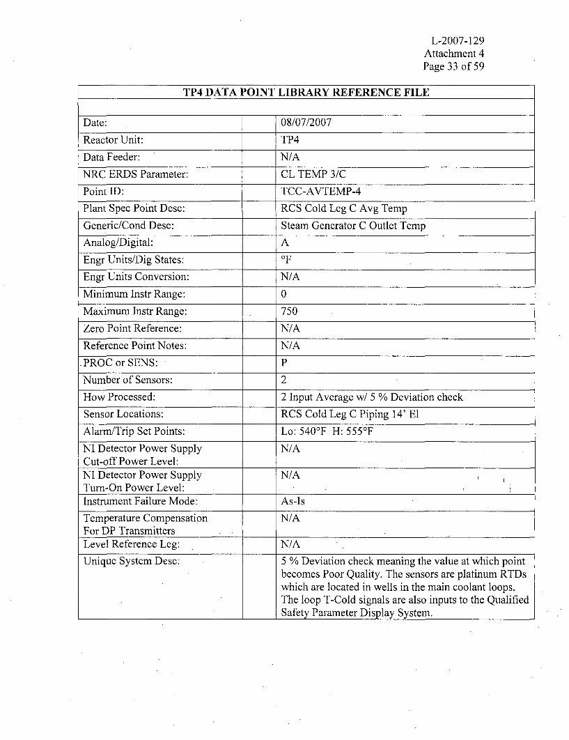
L-2007-129Attachment 4Page 33 of 59
TP4 DATA POINT LIBRARY REFERENCE FILE
Date: 08/07/2007
Reactor Unit: TP4
Data Feeder: N/A
NRC ERDS Parameter: CL TEMP 3/C
Point ID: TCC-AVTEMP-4
Plant Spec Point Desc: RCS Cold Leg C Avg Temp
Generic/Cond Desc: Steam Generator C Outlet Temp
Analog/Digital: A
Engr Units/Dig States: OF
Engr Units Conversion: N/A
Minimum Instr Range: 0
Maximum Instr Range: 750
Zero Point Reference: N/A
Reference Point Notes: N/A
PROC or SENS: P
Number of Sensors: 2
How Processed: 2 Input Average w/ 5 % Deviation check
Sensor Locations: RCS Cold Leg C Piping 14' El
Alarm/Trip Set Points: Lo: 540'F H: 555°F
NI Detector Power Supply N/ACut-off Power Level:NI Detector Power Supply N/ATurn-On Power Level:Instrument Failure Mode: As-Is
Temperature Compensation N/AFor DP TransmittersLevel Reference Leg: N/A
Unique System Desc: 5 % Deviation check meaning the value at which pointbecomes Poor Quality. The sensors are platinum RTDswhich are located in wells in the main coolant loops.The loop T-Cold signals are also inputs to the QualifiedSafety Parameter Display System.

L-2007-129Attachment 4Page 34 of 59
TP4 DATA POINT LIBRARY REFERENCE FILE
Date: 08/07/2007
Reactor Unit: TP4
Data Feeder: N/A
NRC ERDS Parameter: RCS PRESSURE
Point ID: RCSAVPRES-4
Plant Spec Point Desc: RCS Pressure WR
Generic/Cond Desc: Reactor Coolant System Pressure
Analog/Digital: A
Engr Units/Dig States: psig
Engr Units Conversion: N/A
Minimum Instr Range:. 0
Maximum Instr Range: 3000
Zero Point Reference: N/A
Reference Point Notes: N/A
PROC or SENS: P
Number of Sensors: 2
How Processed: 2 Input Average w/ 5 % Deviation check
Sensor Locations: RCS Loop A & B Hot Legs 14' El
Alann/Trip Set Points: Lo: 1910 psig Hi: 2310 psig
NI Detector Power Supply N/ACut-off Power Level:NI Detector Power Supply N/ATurn-On Power Level:Instrument Failure Mode: As-Is
Temperature Compensation N/AFor DP TransmittersLevel Reference Leg: N/A
Unique System Desc: RCS pressure is the average of 2 inputs (P404 & P406).5 % Deviation check meaning the value at which pointbecomes Poor Quality.

L-2007-129Attachment 4Page 35 of 59
TP4 DATA POINT LIBRARY REFERENCE FILE
Date: 08/07/2007
Reactor Unit: TP4
Data Feeder: N/A
NRC ERDS Parameter: PRZR LEVEL
Point ID: PRZ-AVLVL-4
Plant Spec Point Desc: Pressurizer Average Level
Generic/Cond Desc: Primary System Pressurizer Level
Analog/Digital: A
Engr Units/Dig States: %
Engr Units Conversion: 1% 84.5 gallons
Minimum Instr Range: 0
Maximum Instr Range: 100
Zero Point Reference: Complx
Reference Point Notes: N/A
PROC or SENS: P
Number of Sensors: 3
How Processed: 3 Input Average
Sensor Locations: PRZ Vessel 30' ElAlarm/Trip Set Points: Lo: 14% Hi: 92%
NI Detector Power Supply N/ACut-off Power Level:NI Detector Power Supply N/ATurn-On Power Level:Instrument Failure Mode: As-Is
Temperature Compensation NoFor DP TransmittersLevel Reference Leg: Wet
Unique System Desc: The pressurizer average level is calculated using 5minute rolling averages of 3 redundant sensors. Theinstrument range of 0-100% is equivalent to 600-9050gallons. Protection Channel inputs include: PZR Hi-Level Rx trip (2/3 at 9 1%), Lo-Lo level alarm at 6%,PZR heaters Off and letdown isolate at 14.4%, Hi levelalarm and heaters on at +5% program, and Lo levelalarm at -5% program.

L-2007-129Attachment 4Page 36 of 59
TP4 DATA POINT LIBRARY REFERENCE FILE
Date: 08/07/2007
Reactor Unit: TP4
Data Feeder: N/A
NRC ERDS Parameter: RCS CHG/MU
Point ID: FT122-4
Plant Spec Point Desc: Charging Flow
Generic/Cond Desc" Primary System Charging/MU Flow
Analog/Digital: A
Engr Units/Dig States: gpm
Engr Units Conversion: N/A
Minimum Instr Range: 0
Maximum Instr Range: 150
Zero Point Reference: N/A
Reference Point Notes: N/A
PROC or SENS: S
Number of Sensors: 1
How Processed: N/A
Sensor Locations: Charging Pumps Discharge Header
Alanr/Trip Set Points: N/A
NI Detector Power Supply N/ACut-off Power Level:NI Detector Power Supply N/A I:,
Turn-On Power Level:Instrument Failure Mode: Low
Temperature Compensation NoFor DP TransmittersLevel Reference Leg: N/A
Unique System Desc: Charging flow is provided by 3 electrically drivenpositive displacement pumps. The discharge is to acommon header (where the flow is measured) andprovides cooled RCP seal water flow and re-heatedflow that can be directed to loops A cold leg, C hot leg,or to the pressurizer auxiliary spray line. Chargingflow rate is normally controlled by pressurizer level.

L-2007-129Attachunent 4Page 37 of 59
TP4 DATA POINT LIBRARY REFERENCE FILE
Date: 08/07/2007
Reactor Unit: TP4
Data Feeder: N/A
NRC ERDS Parameter: NL
Point ID: FT932-4
Plant Spec Point Desc: HHSI Flo A HL Inside Containment
Generic/Cond Desc: High Press SI Flow To HL A
Analog/Digital: A
Engr Units/Dig States: gpm
Engr Units Conversion: N/A
Minimum Instr Range: 0
Maximum Instr Range: 600
Zero Point Reference: N/A
Reference Point Notes: N/A
PROC or SENS: S
Number of Sensors: 1
How Processed: N/A
Sensor Locations: On SI line to Hot Leg A 14' El
Alarm/Trip Set Points: N/A
NI Detector Power Supply N/ACut-off Power Level:NI Detector Power Supply N/ATurn-On Power Level:Instrument Failure Mode: Low
Temperature Compensation NoFor DP TransmittersLevel Reference Leg: N/A
Unique System Desc: FT-932 measures HHSI flow to the loop A hot leg.HHSI is provided by 2 electrically driven pumps. Thewater supply is the Unit 3 RWST. The discharge ofeach pump is directed to a common discharge header tothe A and/or B hot legs. Note: The Unit 3 & 4 RWSTsmay be cross-connected and Unit 3 & 4 HHSI pumpsdischarge headers may be cross-connected.

L-2007-129Attachment 4Page 38 of 59
TP4 DATA POINT LIBRARY REFERENCE FILE
Date: 08/07/2007
Reactor Unit: TP4
Data Feeder: N/A
NRC ERDS Parameter: NL
Point ID: FT933-4
Plant Spec Point Desc: HHSI Flo B HL Inside Containment
Generic/Cond Desc: High Press SI Flow To HL B
Analog/Digital: A
Engr Units/Dig States: gpm
Engr Units Conversion: N/A
Minimum Instr Range: 0
Maximum Instr Range: 600
Zero Point Reference: N/A
Reference Point Notes: N/A
PROC or SENS: S
Number of Sensors: 1
How Processed: N/A
Sensor Locations: On SI line to Hot Leg B 14' El
Alarm/Trip Set Points: N/A
NI Detector Power Supply N/ACut-off Power Level:NI Detector Power Supply N/ATurn-On Power Level:Instrument Failure Mode: Low
Temperature Compensation NoFor DP TransmittersLevel Reference Leg: N/A
Unique System Desc: FT-933 measures HHSI flow to loop A and/or B hotlegs. HHSI is provided by 2 electrically driven pumps.The water supply is the Unit 3 RWST. The dischargeof each pump is directed to a common discharge headerto the A and/or B hot legs. Note: The Unit 3 & 4RWSTs may be cross-connected and Unit 3 & 4 HHSIpumps discharge headers may be cross-connected.

L-2007-129Attachment 4Page 39 of 59
TP4 DATA POINT LIBRARY REFERENCE FILE
Date: 08/07/2007
Reactor Unit: TP4
Data Feeder: N/A
NRC ERDS Parameter: HPSI FLOW
Point ID: FT943-4
Plant Spec Point Desc: HHSI Flo To BIT To Cold Legs
Generic/Cond Desc: High Press SI Flow To Cold Legs
Analog/Digital: A
Engr Units/Dig States: gpm
Engr Units Conversion: N/A
Minimum Instr Range: 0
Maximum Instr Range: 1000
Zero Point Reference: N/A
Reference Point Notes: N/A
PROC or SENS: S
Number of Sensors: 1
How Processed: N/A
Sensor Locations: SI line upstream of Discharge Header MOVs
Alarm/Trip Set Points: N/A
NI Detector Power Supply N/ACut-off Power Level:NI Detector Power Supply N/ATurn-On Power Level:Instrument Failure Mode: Low
Temperature Compensation NoFor DP TransmittersLevel Reference Leg: N/A
Unique System Desc: FT-943 measures total HHSI flow to loops A, B, and Ccold legs. HHSI is provided by 2 electrically drivenpumps. The water supply is the Unit 3 RWST. Thedischarge of each pump is directed to a commondischarge header to the 3 cold legs. Note: The Unit 3& 4 RWSTs may be cross-connected and Unit 3 & 4HHSI pumps discharge headers may be cross-connected.

L-2007-129Attachment 4Page 40 of 59
TP4 DATA POINT LIBRARY REFERENCE FILE
Date: 08/07/2007
Reactor Unit: TP4
Data Feeder: N/A
NRC ERDS Parameter: LP SI FLOW
Point ID: FT605-4
Plant Spec Point Desc: RHR System Flow
Generic/Cond Desc: Lo Pressure SI Flow
Analog/Digital: A
Engr Units/Dig States: gpm
Engr Units Conversion: N/A
Minimum Instr Range: 0
Maximum Instr Range: 8500
Zero Point Reference: N/A
Reference Point Notes: N/A
PROC or SENS: S
Number of Sensors: , 1
How Processed: N/A
Sensor Locations: RHR/SI Header to Cold Legs (in RHR HX Room)
Alarm/Trip Set Points: Hi: 7000 gpm
NI Detector Power Supply N/ACut-off Power Level:NI Detector Power Supply N/ATurn-On Power Level:Instrument Failure Mode: Low
Temperature Compensation NoFor DP TransmittersLevel Reference Leg: N/A
Unique System Desc: FT-605 measures the Residual Heat Removal (RHR)flow. RHR is provided by 2 RHR pumps. Each pumpdischarges to its own associated heat exchanger. Flowfrom the heat exchangers are combined into a singleheader for penetration into containment. Flow in thisheader is measured by FT-605, flow is then directed toloops A, B, and C cold legs. This flow signal alsoactuates a low flow alarm annunciator at 3000 gpm.

L-2007-129Attachment 4Page 41 of 59
TP4 DATA POINT LIBRARY REFERENCE FILE
Date: 08/07/2007
Reactor Unit: TP4
Data Feeder: N/A
NRC ERDS Parameter: CTMNT SMP NR
Point ID: CTMTHILVLL-4
Plant Spec Point Desc: CNTMT LR Sump Water Level
Generic/Cond Desc: Containment Sump Lo-Range Level
Analog/Digital: A
Engr Units/Dig States: Inches
Engr Units Conversion: N/A
Minimum Instr Range: 0
Maximum Instr Range: 369
Zero Point Reference: -18' 8" El
Reference Point Notes: N/A
PROC or SENS: P
Number of Sensors: 2
How Processed: 2 Input Hi Select w/ 5% Deviation check
Sensor Locations: Containment Sump
Alarm/Trip Set Points: N/A
NI Detector Power Supply N/ACut-off Power Level:NI Detector Power Supply N/ATurn-On Power Level:Instrument Failure Mode: As-Is
Temperature Compensation N/AFor DP TransmittersLevel Reference Leg: N/A
Unique System Desc: Containment sump level is the highest of the two sumplevel channels. Each channel consists of 5 segment,float and reed switch level column. The level columnstarts at the -18'8" elevation (i.e., below sea level) andcovers 30'9" of level. The conversion from inches togallons is non-linear. Note: The elevation between 12'and 14'3" is not covered by the containment sump orcontainment level transmitters.

L-2007-129Attachment 4Page 42 of 59
TP4 DATA POINT LIBRARY REFERENCE FILE
Date: 08/07/2007
Reactor Unit: TP4
Data Feeder: N/A
NRC ERDS Parameter: CTMNT SMP WR
Point ID: CTMTHILVLH-4
Plant Spec Point Desc: CNTMT HR Water Level
Generic/Cond Desc:. Containment Sump Hi-Range Level
Analog/Digital: A
Engr Units/Dig States: Inches
Engr Units Conversion: N/A
Minimum Instr Range: 397
Maximum Instr Range: 487.5
Zero Point Reference: N/A
Reference Point Notes: N/A
PROC or SENS: P
Number of Sensors: 2
How Processed: 2 Input Hi Select
Sensor Locations: Containment Floor 14' El & Above
Alarm/Trip Set Points: N/A
NI Detector Power Supply N/ACut-off Power Level:NI Detector Power Supply N/ATurn-On Power Level:Instrument Failure Mode: As-Is
Temperature Compensation N/AFor DP TransmittersLevel Reference Leg: N/A
Unique System Desc: Containment level is the highest of the 2 containmentlevel channels. Each channel consists of a float andreed switch level column. The level column starts atthe 14'3" elevation and covers 7'6" of level. Theconversion from inches to gallons is non-linear. Note:The elevation between 12' and 14'3" is not covered bythe containment sump or containment leveltransmitters.

L-2007-129Attachment 4Page 43 of 59
TP4 DATA POINT LIBRARY REFERENCE FILE
Date: 08/07/2007
Reactor Unit: TP4
Data Feeder: N/A
NRC ERDS Parameter: NL
Point ID: R14-4
Plant Spec Point Desc: Plant Vent Gas Activity
Generic/Cond Desc: Radioactivity Of A Released Gas
Analog/Digital: A
Engr Units/Dig States: cpm
Engr Units Conversion: N/A
Minimum Instr Range: 10
Maximum Instr Range: 1 E6
Zero Point Reference: N/A
Reference Point Notes: N/A
PROC or SENS: S
Number of Sensors: I
How Processed: N/A
Sensor Locations: Top Of Plant Vent Stack
Alarm/Trip Set Points: Determined By Radiochemist
NI Detector Power Supply N/ACut-off Power Level:NI Detector Power Supply N/ATurn-On Power Level:Instrument Failure Mode: Low
Temperature Compensation N/AFor DP TransmittersLevel Reference Leg: N/A
Unique System Desc: R-14 is installed inside the plant vent. It consists of 4thin-walled Gieger-Mueller tube detectors arrangedacross the plant vent stack diameter. The 4 detectorsoperate in parallel, are Beta-Gamma sensitive in therange of 5E7 to 1E-4 Ci/cc, and have a check source.R-14 alarm will automatically close the Gas DecayTank discharge valve upon actuation. Note: cpm touCi/cc conversion factor is 2E8 ml/cc at sample flowrate.

L-2007-129Attaclhnent 4Page 44 of 59
TP4 DATA POINT LIBRARY REFERENCE FILE
Date: 08/07/2007
Reactor Unit: TP4
Data Feeder: N/A
NRC ERDS Parameter: EFF GAS RAD
Point ID: RAD6304HR-4
Plant Spec Point Desc: Plant Vent Gas Gamma Hi Range
Generic/Cond Desc: Radioactivity Of Released Gases
Analog/Digital: A
Engr Units/Dig States: uCi/cc
Engr Units Conversion: N/A
Minimum Instr Range: 1.OE1
Maximum Instr Range: 1.0E5
Zero Point Reference: N/A
Reference Point Notes: N/A
PROC or SENS: P
Number of Sensors: 1
How Processed: Data Link
Sensor Locations: Auxiliary Building
Alarm/Trip Set Points: N/A
NI Detector Power Supply N/ACut-off Power Level:NI Detector Power Supply N/ATurn-On Power Level:Instrument Failure Mode: As-Is
Temperature Compensation N/AFor DP TransmittersLevel Reference Leg: N/A
Unique System Desc: An Eberline SPING Unit provides Plant Vent HighRange Noble Gas Activity. The detector type is aGeiger-Mueller tube, uncompensated with a checksource. The plant vent stack is the normal dischargepath for: Unit 3 & 4 containment purge, auxiliarybuilding exhaust and Unit 4 SFP. Note: Unit 3 SFPexhaust is through a dedicated stack.

L-2007-129Attachment 4Page 45 of 59
TP4 DATA POINT LIBRARY REFERENCE FILE
Date: 08/07/2007
Reactor Unit: TP4
Data Feeder: N/A
NRC ERDS Parameter: NL
Point ID: RAD6304FLO-4
Plant Spec Point Desc: Plant Vent Flow Rate
Generic/Cond Desc: Plant Vent Stack Flow Rate
Analog/Digital: A
Engr Units/Dig States: cfmn
Engr Units Conversion: N/A
Minimum Instr Range: 0
Maximum Instr Range: 1.5E÷5
Zero Point Reference: N/A
Reference Point Notes: N/A
PROC or SENS: P
Number of Sensors: 1
How Processed: Data Link
Sensor Locations: Plant Vent Stack Near Top
Alarm/Trip Set Points: N/A
NI Detector Power Supply N/ACut-off Power Level:NI Detector Power Supply N/ATurn-On Power Level:Instrument Failure Mode: As-Is
Temperature Compensation N/AFor DP TransmittersLevel Reference Leg: N/A
Unique System Desc: Plant vent flow is provided by transmitter FT-6584which measures the differential pressure across a floworifice installed in the plant vent stack. The signal isprocessed by an optional analog to digital channel(#10) on the Plant Vent SPING unit. Note: Loss ofplant vent flow channel will not affect the calibrationof the plant vent high range gas monitor which is basedon a fixed sample flow rate.
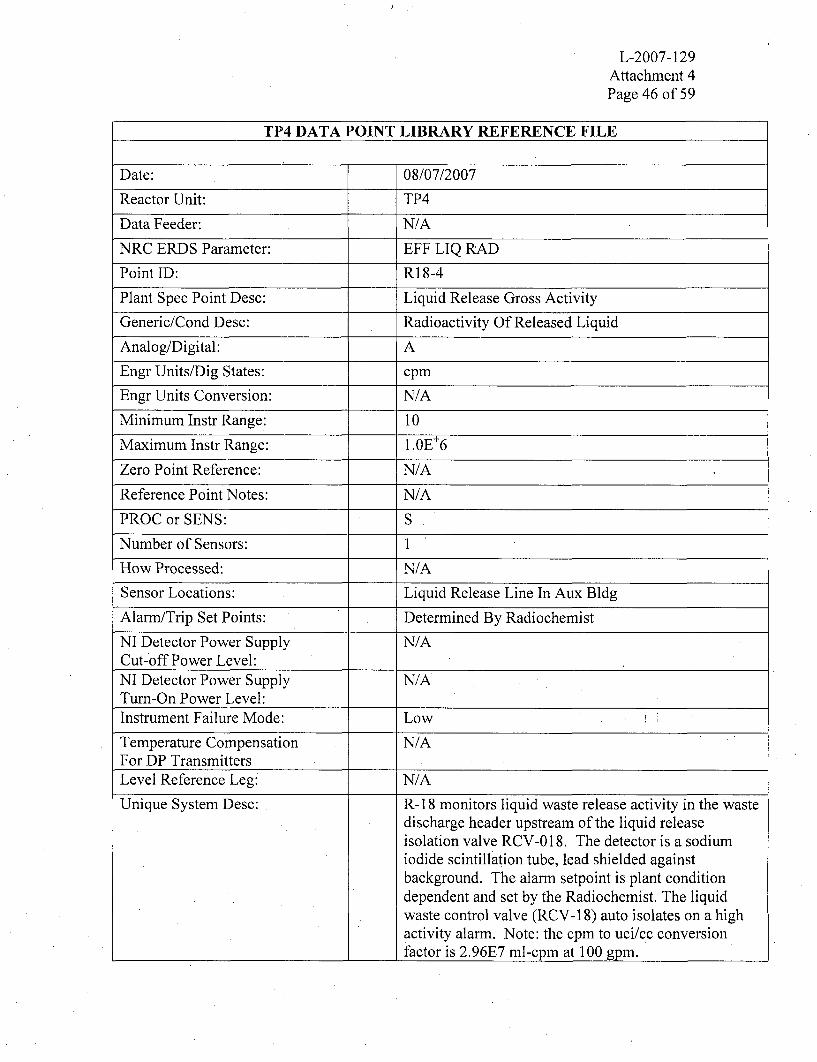
L-2007-129Attachment 4Page 46 of 59
TP4 DATA POINT LIBRARY REFERENCE FILE
Date: 08/07/2007
Reactor Unit: TP4
Data Feeder: N/A
NRC ERDS Parameter: EFF LIQ RAD
Point ID: R18-4
Plant Spec Point Desc: Liquid Release Gross Activity
Generic/Cond Desc: Radioactivity Of Released Liquid
Analog/Digital: A
Engr Units/Dig States: cpm
Engr Units Conversion: N/A
Minimum Instr Range: 10
Maximum Instr Range: 1.0E+6
Zero Point Reference: N/A
Reference Point Notes: N/A
PROC or SENS: S
Number of Sensors: 1
How Processed: N/A
Sensor Locations: Liquid Release Line In Aux Bldg
Alarm/Trip Set Points: Determined By Radiochemist
NI Detector Power Supply N/ACut-off Power Level:NI Detector Power Supply N/ATurn-On Power Level:Instrument Failure Mode: Low
Temperature Compensation N/AFor DP TransmittersLevel Reference Leg: N/A
Unique System Desc: R- 18 monitors liquid waste release activity in the Wastedischarge header upstream of the liquid releaseisolation valve RCV-0 18. The detector is a sodiumiodide scintillation tube, lead shielded againstbackground. The alarm setpoint is plant conditiondependent and set by the Radiochemist. The liquidwaste control valve (RCV-18) auto isolates on a highactivity alarm. Note: the cpm to uci/cc conversionfactor is 2.96E7 ml-cpm at 100 gpm.

L-2007-129Attachment 4Page 47 of 59
TP4 DATA POINT LIBRARY REFERENCE FILE
Date: 08/07/2007
Reactor Unit: TP4
Data Feeder: N/A
NRC ERDS Parameter: NL
Point ID: R15-4
Plant Spec Point Desc: Condenser Air Ejector (PRMS)
Generic/Cond Desc: Condenser Air Ejector Rad
Analog/Digital: A
Engr Units/Dig States: cpm
Engr Units Conversion: N/A
Minimum Instr Range: 10
Maximum Instr Range: 1.0E+6
Zero Point Reference: N/A
Reference Point Notes: N/A
PROC or SENS: S
Number of Sensors: 1
How Processed: N/A
Sensor Locations: TURBINE DECK
Alarm/Trip Set Points: DETERMINED BY RADIOCHEMIST
NI Detector Power Supply N/ACut-off Power Level:NI Detector Power Supply N/ATurn-On Power Level:Instrument Failure Mode: Low
Temperature Compensation N/AFor DP TransmittersLevel Reference Leg: N/A
Unique System Desc: R-15, the Condenser Air Ejector Monitor uses a thinwall Geiger-Mueller tube detector. The detector islocated in the air ejector exhaust manifold and useslead shielding against background. The alarm setpointis plant condition dependent and is determined by theRadiochemist.

L-2007-129Attachnment 4Page 48 of 59
TP4 DATA POINT LIBRARY REFERENCE FILE
Date: 08/07/2007
Reactor Unit: TP4
Data Feeder: N/A
NRC ERDS Parameter: COND A/E RAD
Point ID: RAD6417HR-4
Plant Spec Point Desc: Air Ejector Gas Gamma Hi-Rng
Generic/Cond Desc: Condenser Air Ejector Rad
Analog/Digital: A
Engr Units/Dig States: uCi/cc
Engr Units Conversion: N/A
Minimum Instr Range: 1.OE-1
Maximum Instr Range: 1.0E+5
Zero Point Reference: N/A
Reference Point Notes: N/A
PROC or SENS: P
Number of Sensors: 1
How Processed: Data Link
Sensor Locations: Turbine Deck
Alarm/Trip Set Points: Determined By Radiochemist
NI Detector Power Supply N/ACut-off Power Level:NI Detector Power Supply N/ATurn-On Power Level:Instrument Failure Mode: As-Is
Temperature Compensation N/AFor DP TransmittersLevel Reference Leg: M/A
Unique System Desc: An Eberline SPING Unit provides the Air Ejector PlantVent Hi-Range Noble Gas Activity. The detector typeis a Gieger-Mueller tube, uncompensated with a checksource.

L-2007-129Attachment 4Page 49 of 59
TP4 DATA POINT LIBRARY REFERENCE FILE
Date: 08/07/2007
Reactor Unit: TP4
Data Feeder: N/A
NRC ERDS Parameter: CNTMT RAD
Point ID: CTMHRADW-4
Plant Spec Point Desc: Containment Radiation (WR)
Generic/Cond Desc: Radiation Level In Containment
Analog/Digital: A
Engr Units/Dig States: R/Hr
Engr Units Conversion: N/A
Minimum Instr Range: 1.0
Maximum Instr Range: 1.0E+8
Zero Point Reference: N/A
Reference Point Notes: N/A
PROC or SENS: P
Number of Sensors: 2
How Processed: 2 Input Hi Select w/ 5 % Deviation limit
Sensor Locations:t Rx Bldg @ 25' & 64' ElAlann/Trip Set Points: Hi: 1.3E4 R/Hr Hi-Hi: 1.3E5 R/Hr
NI Detector Power Supply N/ACut-off Power Level:NI Detector Power Supply N/ATurn-On Power Level:Instrument Failure Mode: As-Is
Temperature Compensation N/AFor DP TransmittersLevel Reference Leg: N/A
Unique System Desc: CNTMT RAD is the higher of 2 channel inputs(RAD6311A and RAD6311B). Both use ion chamberdetectors. RAD631 1A is located inside containment onthe 25' level near the personnel hatch and RAD631 lBis near the 64' level on the SG shield wall near thepressurizer ARMS channel R-2. These channels have2 Hi Alarm setpoints, the first one activating anannunciator.

L-2007-129Attachment 4Page 50 of 59
TP4 DATA POINT LIBRARY REFERENCE FILE
Date: 08/07/2007
Reactor Unit: TP4
Data Feeder: N/A
NRC ERDS Parameter: RCS LTDN RAD
Point ID: R20-4
Plant Spec Point Desc: RCS Letdown Line Activity
Generic/Cond Desc: Rad Level Of The RCS Letdown
Analog/Digital: A
Engr Units/Dig States: mR/Hr
Engr Units Conversion: N/A
Minimum Instr Range: 1.0
Maximum Instr Range: 1.0E+5
Zero Point Reference: N/A
Reference Point Notes: N/A
PROC or SENS: S
Number of Sensors: 1
How Processed: N/A
Sensor Locations: RCS letdown piping upstream of HX
Alarm/Trip Set Points: Hi 5.0E+4 mR/Hr
NI Detector Power Supply N/ACut-off Power Level:NI Detector Power Supply N/ATurn-On Power Level:Instrument Failure Mode: Low
Temperature Compensation N/AFor DP TransmittersLevel Reference Leg: N/A
Unique System Desc: R-20 provides reactor coolant letdown line activity.The monitor is located on the letdown line, outside ofcontainment and upstream of the non-regenerative heatexchanger. The monitor is external to the pipingsystem and far enough from the coolant loop that a 40second transient time is provided for N 16 gammadecay. The detector is a Geiger-Mueller tube.

L-2007-129Attaclhnent 4Page 51 of 59
TP4 DATA POINT LIBRARY REFERENCE FILE
Date: 08/07/2007
Reactor Unit: TP4
Data Feeder: N/A
NRC ERDS Parameter: N/L
Point ID: RAD6426-4
Plant Spec Point Desc: Main Stm Lines Gamma Hi Rng
Generic/Cond Desc: Main Steam Lines Radioactivity
Analog/Digital: A
Engr Units/Dig States: uCi/cc
Engr Units Conversion: N/A
Minimum Instr Range: 1.OE-1
Maximum Instr Range: 1.0E+5
Zero Point Reference: N/A
Reference Point Notes: N/A
PROC or SENS: P
Number of Sensors: 1
How Processed: Data Link
Sensor Locations: Main Steam Sample lines
Alarm/Trip Set Points: Determined By Plant Radiochemist
NI Detector Power Supply N/ACut-off Power Level:NI Detector Power Supply N/ATurn-On Power Level:Instrument Failure Mode: As-Is
Temperature Compensation N/AFor DP TransmittersLevel Reference Leg: N/A
Unique System Desc: RAD6426-Main Steam Line High Range Gamma ismeasured by the Eberline DAM-1. Detector type is aGieger-Mueller Tube with no compensation. Note:sample lines from all 6 SGs run simultaneously throughthe detector. To identify a ruptured SG, manualisolation valves must be operated.

L-2007-129Attachment 4Page 52 of 59
TP4 DATA POINT LIBRARY REFERENCE FILE
Date: 08/07/2007
Reactor Unit: TP4
Data Feeder: N/A
NRC ERDS Parameter: NL
Point ID: R19-4
Plant Spec Point Desc: Stm Gen Liquid Sample Activity
Generic/Cond Desc: SG Blowdown Radioactivity
Analog/Digital: A
Engr Units/Dig States: cpm
Engr Units Conversion: N/A
Minimum Instr Range: 10
Maximum Instr Range: 1.0E+6
Zero Point Reference: N/A
Reference Point Notes: N/A
PROC or SENS: S
Number of Sensors: 1
How Processed: N/A
Sensor Locations: Auxiliary Bldg N-S Hallway
Alarm/Trip Set Points: Determined By Radiochemist
NI Detector Power Supply N/ACut-off Power Level:NI Detector Power Supply N/ATurn-On Power Level:Instrument Failure Mode: 10
Temperature Compensation N/AFor DP TransmittersLevel Reference Leg: N/A
Unique System Desc: Detector type - Scintillation. Located in the combinedSG sample line. R-19 provides for auto closure of all 3(Unit 3) SG sample lines, all 3 blowdown flow controlvalves, and both (2) blowdown tank drain valves. HighAlarm setpoint is determined by Radiochemist basedon plant conditions.

L-2007-129Attachment 4Page 53 of 59
TP4 DATA POINT LIBRARY REFERENCE FILE
Date: 08/07/2007
Reactor Unit: TP4
Data Feeder: N/A
NRC ERDS Parameter: CTMNT PRESS
Point ID: CTMTAVPRSW-4
Plant Spec Point Desc: Containment Pressure (WR)
Generic/Cond Desc: Containment Pressure
Analog/Digital: A
Engr Units/Dig States: psig
Engr Units Conversion: N/A
Minimum Instr Range: 0
Maximum Instr Range: 180
Zero Point Reference: N/A
Reference Point Notes: N/A
PROC or SENS: P
Number of Sensors: 2
How Processed: 2 Input Average w/ 5 % Deviation check
Sensor Locations: South Penetration Room
Alarnm/Trip Set Points: Hi: 20 psig Hi-Hi: 55 psig
NI Detector Power Supply N/ACut-off Power Level:NI Detector Power Supply N/ATurn-On Power Level:Instrument Failure Mode: As-Is
Temperature Compensation N/AFor DP TransmittersLevel Reference Leg: N/A
Unique System Desc: 5 % Deviation check meaning the value at which pointbecomes Poor Quality. Containment pressuretransmitters provide containment Hi and Hi-Hiactuation of the ESFAS circuitry at 4 psig and 20 psigrespectively. Hi containment pressure actuates SafetyInjection, while the Hi-Hi pressure coincident with theHi pressure will actuate containment sprays and PhaseB Containment Isolation.

L-2007-129Attachment 4Page 54 of 59
TP4 DATA POINT LIBRARY REFERENCE FILE
Date: 08/07/2007
Reactor Unit: TP4
Data Feeder: N/A
NRC ERDS Parameter: CTMNT TEMP
Point ID: CTMTHITMP-4
Plant Spec Point Desc: Containment Temperature
Generic/Cond Desc: Containment Temperature
Analog/Digital: A
Engr Units/Dig States: OF
Engr Units Conversion: N/A
Minimum Instr Range: 0
Maximum Instr Range: 300
Zero Point Reference: N/A
Reference Point Notes: N/A
PROC or SENS: P
Number of Sensors: 3
How Processed: 3 Input Hi Select
Sensor Locations: Containment El 58' @ 1200 Intervals
Alarm/Trip Set Points: N/A
NI Detector Power Supply N/ACut-off Power Level:NI Detector Power Supply N/ATurn-On Power Level:Instrument Failure Mode: As-Is
Temperature Compensation N/AFor DP TransmittersLevel Reference Leg: N/A
Unique System Desc: The containment temperature is the average of 3channels (TE6700, TE6701, and TE6702). Eachchannel uses platinum RTD. TE6700 is located nearthe 3B Normal Containment Cooler, TE6701 is locatednear the 3C Normal Containment Cooler, TE6702 islocated near the 3C Emergency Containment Filters.

L-2007-129Attachment 4Page 55 of 59
TP4 DATA POINT LIBRARY REFERENCE FILE
Date: 08/07/2007
Reactor Unit: TP4
Data Feeder: N/A
NRC ERDS Parameter: H2 CONC
Point ID: CTMTH2CONC-4
Plant Spec Point Desc: CTMT Hydrogen Concentration
Generic/Cond Desc: Containment Atmosphere H2 Conc
Analog/Digital: A
Engr Units/Dig States: % H2
Engr Units Conversion: N/A
Minimum Instr Range: 0
Maximum Instr Range: 10
Zero Point Reference: N/A
Reference Point Notes: N/A
PROC or SENS: P
Number of Sensors: 2
How Processed: 2 Input Hi Select w/ 5 % Deviation check
Sensor Locations: Aux Bldg Basement
Alarn/Trip Set Points: 4%
NI Detector Power Supply N/ACut-off Power Level:NI Detector Power Supply N/ATurn-On Power Level:Instrument Failure Mode: AS-IS
Temperature Compensation N/AFor DP TransmittersLevel Reference Leg: N/A
Unique System Desc: Two channels of instrumentation are provided, thehighest which is reported. A % H2 signal is developedby comparing the thermal conductivity of a referencesample with the conductivity of a sample afterremoving any nitrogen. The system provides a high H2
annunciator alarm at 7.5%, Low and Hi Cell Failure,Calibration Gas Low Pressure, Reagent Gas LowPressure, and Low Analyzer Flow Alarm.

L-2007-129Attachment 4Page 56 of 59
TP4 DATA POINT LIBRARY REFERENCE FILE
Date: 08/07/2007
Reactor Unit: TP4
Data Feeder: N/A
NRC ERDS Parameter: RWST LEVEL
Point ID: RWST3AVLVL-4
Plant Spec Point Desc: RWST (Unit 3) Average Level
Generic/Cond Desc: Borated Water Storage Tank Level
Analog/Digital: A
Engr Units/Dig States: gal
Engr Units Conversion: N/A
Minimum Instr Range: 0
Maximum Instr Range: 335,000 gals
Zero Point Reference: TNKBOT
Reference Point Notes: N/A
PROC or SENS: P
Number of Sensors: 2
How Processed: 2 Input Average w/ 5 % Deviation check
Sensor Locations: Ground Level by RWST
AlannlTrip Set Points: See Description
NI Detector Power Supply N/ACut-off Power Level:NI Detector Power Supply N/ATurn-On Power Level:Instrument Failure Mode: AS-IS
Temperature Compensation N/AFor DP TransmittersLevel Reference Leg: DRY
Unique System Desc: 5 % Deviation check meaning the value at which pointbecomes Poor Quality. Each RWST level loop consistsof a Rosemount DP transmitter and Foxboro Modulesto provide alarm and indication functions. Alarmsprovided are: Lo-Lo Level at 60,000 gallons, LowLevel at 155,000 gallons, Tech Spec Min Level at322,000 gallons and Hi Level at 333,000 gallons.Note: the RWST is the Borated Water Storage Tank.

L-2007-129Attachment 4Page 57 of 59
TP4 DATA POINT LIBRARY REFERENCE FILE
Date: 08/07/2007
Reactor Unit: TP4
Data Feeder: N/A
NRC ERDS Parameter: WIND SPEED
Point ID: WS-1OM-TP-4
Plant Spec Point Desc: 10 Meter Wind Speed (T.P.)
Generic/Cond Desc: Wind Speed At Reactor Site
Analog/Digital: A
Engr Units/Dig States: mph
Engr Units Conversion: N/A
Minimum Instr Range: 0
Maximum Instr Range: 100
Zero Point Reference: N/A
Reference Point Notes: N/A
PROC or SENS: S
Number of Sensors: 1
How Processed: N/A
Sensor Locations: 10 Meter Tower 1 Mile SW of Plant
Alarm/Trip Set Points: Hi: 75 mph Hi-Hi: 90 mph
NI Detector Power Supply N/ACut-off Power Level:NI Detector Power Supply N/ATurn-On Power Level:Instrument Failure Mode: 0
Temperature Compensation N/AFor DP TransmittersLevel Reference Leg: N/A
Unique System Desc: Wind Speed meteorological data is gathered byinstruments mounted on a 10 meter tower. The data (a15 minute running average) is transmitted by radio tothe plant and is received by the Campbell Scientificequipment located in the Plant Computer Room.

L-2007-129Attachmnent 4Page 58 of 59
TP4 DATA POINT LIBRARY REFERENCE FILE
Date: 08/07/2007
Reactor Unit: TP4
Data Feeder: N/A
NRC ERDS Parameter: WIND DIR
Point ID: WD- 1 OM-TP-4
Plant Spec Point Desc: 10 Meter Wind Direction (T.P.)
Generic/Cond Desc: Wind Direction At Reactor Site
Analog/Digital: A
Engr Units/Dig States: 0 (Degrees)
Engr Units Conversion: N/A
Minimum Instr Range: 0
Maximum Instr Range: 540
Zero Point Reference: N/A
Reference Point Notes: 0 And 360 Are North. Switch Pt 180
PROC or SENS: S
Number of Sensors: 1
How Processed: N/A
Sensor Locations: 10 Meter Tower 1 Mile Sw Of Plant
Alarm/Trip Set Points: N/A
NI Detector Power Supply N/ACut-off Power Level:NI Detector Power Supply N/ATurn-On Power Level:Instrument Failure Mode: 0
Temperature Compensation N/AFor DP TransmittersLevel Reference Leg: N/A
Unique System Desc: Wind direction is provided by instruments mounted ona 10 meter tower. The data (a 15 minute runningaverage) is transmitted by radio to the plant and isreceived by the Campbell Scientific equipment locatedin the Computer Room. The 10 Meter Tower is located1 mile SW of the site. Note: Wind is coming fromdirection reported by the instrument, with 0 and 360being North.

L-2007-129Attachment 4Page 59 of 59
TP4 DATA POINT LIBRARY REFERENCE FILE
Date: 08/07/2007
Reactor Unit: TP4
Data Feeder: N/A
NRC ERDS Parameter: STABB CLASS
Point ID: D-TMP-A-SD-4
Plant Spec Point Desc: Estimate Of Atmos Stability
Generic/Cond Desc: Air Stability At A Reactor Site
Analog/Digital: A
Engr Units/Dig States: df/mnm
Engr Units Conversion: N/A
Minimum Instr Range: -5
Maximum Instr Range: 15
Zero Point Reference: N/A
Reference Point Notes: N/A
PROC or SENS: S
Number of Sensors: 1
How Processed: N/A
Sensor Locations: 60 Meter Tower 7 Miles SSW Of Plant
Alarn/Trip Set Points: N/A
NI Detector Power Supply N/ACut-off Power Level:NI Detector Power Supply N/ATurn-On Power Level:Instrument Failure Mode: -5
Temperature Compensation N/AFor DP TransmittersLevel Reference Leg: N/A
Unique System Desc: Atmospheric stability is developed by taking thedifference between the temperature at the 10 meter and60 meters. The difference is multiplied by 2 to obtainthe change per 100 meters altitude. A 15 minuterunning average data transmitted by radio telemetry toa Campbell Scientific receiver in the Plant ComputerRoom.