TURBOMACHINERY RESEARCH CONSORTIUM ROTORDYNAMICS … · 2 For lateral rotordynamics, XLTRC2 uses a...
20
XLTRC 2 TURBOMACHINERY RESEARCH CONSORTIUM ROTORDYNAMICS SOFTWARE SUITE
Transcript of TURBOMACHINERY RESEARCH CONSORTIUM ROTORDYNAMICS … · 2 For lateral rotordynamics, XLTRC2 uses a...

XLTRC2TURBOMACHINERY RESEARCH CONSORTIUM ROTORDYNAMICS SOFTWARE SUITE

XLTRC2 is a suite of very fast, accurate and experimentally verified, and user- friendly codes for executing a complete lateral and torsional rotordynamic analysis of rotating machinery including pumps, compressors and turbines. Extensive help files are provided for the base and support-library codes. SI or US units can be used interchangeably. XLTRC2 is bundled with no less than twenty five examples of rotordynamic analysis including rotors for compressors, pumps and gas turbines, each model featuring distinctive bearing/seal support conditions and displaying unique characteristics of rotordynamic behavior.
XLTRC2 runs on Windows XP, Vista and Win7, and Microsoft Excel 2003, 2007 and 2010 versions. XLTRC2 also runs on 64-bit Windows operation systems, while maintaining backward compatibility with older systems.
WHAT IS XLTRC2?
1

2
For lateral rotordynamics, XLTRC2 uses a Timoshenko beam, finite-element formulation to model the rotor and housing elements to any degree of accuracy that the analyst feels appropriate. Model dimensionality and execution time are dramatically reduced by using real, zero-running speed modes in a component-mode synthesis formulation. By using real modes (instead of complex modes) the initial modal calculation time is minimized (dramatically), and interpolation and extrapolation of modal parameters is eliminated.Constraint modes are used only at bearing locations and connection points that require nonlinear or frequency-dependent force or moment impedances. XLTRC2 generates rotordynamic results faster than most experienced engineers can input data and evaluate results. Stated differently, engineers don’t wait on XLTRC2.
XLTRC2 uses an Excel-based Graphical User Interface (GUI) to access a suite of rotordynamic codes developed at the Turbomachinery Laboratory (TL) of Texas A&M University (TAMU).The Excel base is ideal for generating or transferring rotordynamic-model data and for translating rotordynamic results into final reports. In addition, the Excel GUI allows a great deal of flexibility for individual or corporate customization.The core of XLTRC2 is optimized with the latest compilers from Intel FORTRAN 10.The IMSL libraries that are used provide fast and accurate computation of results.
HOW DOES XLTRC2 WORK?
3
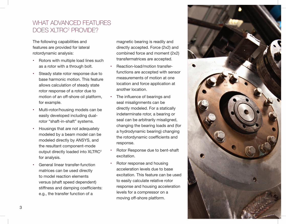
The following capabilities and features are provided for lateral rotordynamic analysis:
• Rotors with multiple load lines such as a rotor with a through bolt.
• Steady state rotor response due to base harmonic motion. This feature allows calculation of steady state rotor response of a rotor due to motion of an off-shore oil platform, for example.
• Multi-rotor/housing models can be easily developed including dual-rotor “shaft-in-shaft” systems.
• Housings that are not adequately modeled by a beam model can be modeled directly by ANSYS, and the resultant component-mode output directly loaded into XLTRC2 for analysis.
• General linear transfer-function matrices can be used directly to model reaction elements versus (shaft speed dependent) stiffness and damping coefficients: e.g., the transfer function of a
magnetic bearing is readily and directly accepted. Force (2x2) and combined force and moment (2x2) transfermatrices are accepted.
• Reaction-load/motion transfer-functions are accepted with sensor measurements of motion at one location and force application at another location.
• The influence of bearings and seal misalignments can be directly modeled. For a statically indeterminate rotor, a bearing or seal can be arbitrarily misaligned, changing the bearing loads and (for a hydrodynamic bearing) changing the rotordynamic coefficients and response.
• Rotor Response due to bent-shaft excitation.
• Rotor response and housing acceleration levels due to base excitation. This feature can be used to easily calculate relative rotor response and housing acceleration levels for a compressor on a moving off-shore platform.
WHAT ADVANCED FEATURES DOES XLTRC2 PROVIDE?
4
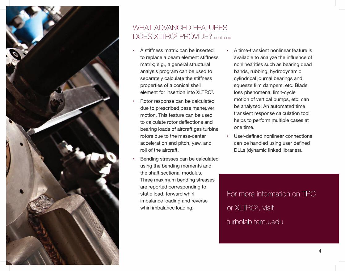
• A stiffness matrix can be insertedto replace a beam element stiffnessmatrix; e.g., a general structuralanalysis program can be used toseparately calculate the stiffnessproperties of a conical shellelement for insertion into XLTRC2.
• Rotor response can be calculateddue to prescribed base maneuvermotion. This feature can be usedto calculate rotor deflections andbearing loads of aircraft gas turbinerotors due to the mass-centeracceleration and pitch, yaw, androll of the aircraft.
• Bending stresses can be calculatedusing the bending moments andthe shaft sectional modulus.Three maximum bending stressesare reported corresponding tostatic load, forward whirlimbalance loading and reversewhirl imbalance loading.
• A time-transient nonlinear feature isavailable to analyze the influence ofnonlinearities such as bearing deadbands, rubbing, hydrodynamiccylindrical journal bearings andsqueeze film dampers, etc. Bladeloss phenomena, limit-cyclemotion of vertical pumps, etc. canbe analyzed. An automated timetransient response calculation toolhelps to perform multiple cases atone time.
• User-defined nonlinear connectionscan be handled using user definedDLLs (dynamic linked libraries).
WHAT ADVANCED FEATURES DOES XLTRC2 PROVIDE? continued
For more information on TRC
or XLTRC2, visit
turbolab.tamu.edu

5
• External torques, constant or time varying, can be specified for each shaft to simulate transient shaft motions during start-up and run-down. Responses to (sudden) imbalances can be readily obtained for rotors supported on fluid.
XLTRC2- TORSION is an independent torsional analysis code incorporated within XLTRC2. It handles configurations with multiple shafts including kinematic and/or flexible constraints at gears. The torsional model code uses the same FEM formulation and modeling techniques as the lateral vibrations code and provides the following features:
• Data form a lateral rotor model can be translated to torsional input worksheets with just a simple click.
• Undamped and damped torsional frequencies can be calculated. Concentrated damping can be specified at bearings as well as shaft damping. Bearing damping is from a rotor station to ground.
Shaft damping arises from relative station motion along the shaft.
• Torsional interference diagrams (Campbell diagram) can be easily created once the undamped (or damped) torsional frequencies are calculated. The line frequencies (usually 60 Hz in USA or 50 Hz in Europe) are used to calculate the slip line speed. A straight line is drawn in the diagram connecting the twice slip line speed (y-axis) to the rotor synchronous speed (x-axis).The torsional frequencies are plotted on the same graph to form a Campbell type diagram.
• Torsional forced (steady-state) response is similar to imbalance response calculation in the lateral analysis.
• Multiple shafts can be connected at specific locations by torsional stiffness and damping for branched systems as well as for closed loop systems.
• Four different motor torque input and output options are available: (a) Synchronous motor with drive torque and pulsating torque input as a function of speed, (b) Synchronous motor with drive torque, pulsating torque and arbitrary pulsating frequency, and (c) Load torque, i.e., input of load torque as a function of speed.
• Torque inputs are used for a startup transient response analysis. The drive and load torques are specified at different stations by assigning them as one of the available types of motor torque inputs.
• Once the data on variation of torque vs. time are available, the user can perform a Cumulative Fatigue Analysis (predicted number of starts the machine will survive).
WHAT ADVANCED FEATURES DOES XLTRC2 PROVIDE? continued

6
Additional features include the display of the film, pressure and temperature fields;
and where applicable, calculation of added mass coefficients. Predictions from
codes validated against test data acquired at TAMU Turbomachinery Laboratory
or in the archival literature.
Exhaustive comparisons to predictions from other codes and classical exact solutions show accurate results with no perceptible errors using XLTRC2.
These comparisons have specifically included rotors with high damping levels at the bearings and heavily damped modes.
HOW ACCURATE IS THE CODE?

7
The base rotordynamics codes provide the strong skeleton for an accurate and efficient structural dynamic rotor and housing model. However, accurate rotor dynamics analysis for real turbomachinery units also requires careful modeling of support bearings, seals, squeeze-film dampers, etc. XLTRC2 provides an unmatched support library to define the dynamic reaction forces developed by these elements. A brief summary of these support codes is provided below. Excel Graphical user interfaces (GUIs) to FORTRAN executable codes. US and SI unit versions are available for each GUI.
LIQUID LUBRICATED HYDRODYNAMIC AND HYDROSTATIC JOURNAL BEARINGS
Codes predict the forced performance of fluid film lubricated journal bearings for rotor lateral support. For a User specified geometry, fluid properties and operating conditions (load and shaft speed), a code calculates the
operating journal eccentricity, flow rate, drag torque, power loss and temperature rise, and (2x2) stiffness and damping rotordynamic force coefficients. Additional features include the display of the film, pressure and temperature fields; and where applicable, calculation of added mass coefficients. Predictions from codes validated against test data acquired at TAMU Turbomachinery Laboratory or in the archival literature
XLJRNL a computer implementation of Someya’s Journal-Bearing DataBook, calculates stiffness and damping coefficients for fixed-arc and tilting-pad bearings on a “table look-up” basis for specific L/D ratios and specified load and shaft speed conditions. XLJrnl is quick and useful for preliminary bearing design work.
XLUSER_ECC, a variation of the code, calculates force coefficients for specified journal eccentricities.
SUPPORTING LIBRARY CODES
8
XLPRESDM (San Andrés) for liquid hydrodynamic bearings operating in the laminar flow regime. Applicable to most commercial oil-lubricated bearings designed as (i) multiple-lobe or rigid-pad arc bearings with a mechanical preload; or (ii) pressure-dam bearings with relief tracks. FE solution of extended Reynolds equation and thermal energy transport equation for thin film laminar flows. Modern code also calculates (2x2) added mass or inertia coefficients.
XLTPJB (San Andrés) for oil lubricated tilting pad bearings operating in the laminar flow regime. Code includes linear and nonlinear models for pivot stiffness; including flexure pivot bearings. FE solution of extended Reynolds equation (with temporal fluid inertia) and thermal energy transport equation for thin film laminar flows. Modern code calculates frequency reduced (2x2) stiffness and damping force coefficients, synchronous with shaft speed or user specified frequency
XLHYDPAD (San Andrés) models hydrostatic and/or hydrodynamic multiple-pad journal bearings operating in the laminar flow regime. Arbitrary geometries can be prescribed for the pockets or recesses (rectangles, triangles, etc.). FE solution of Reynolds equation for liquid thin films with calculation of (2x2) stiffness and damping coefficients.
GAS LUBRICATED HYDRODYNAMIC AND HYDROSTATIC JOURNAL BEARINGS
XLTILTPADHGB (San Andrés) for gas lubricated tilting pad bearings, hydrostatic and hydrodynamic (laminar flow). Exact advection model for solution of Reynolds equation for gas films. Code includes effect of radial, lateral and angular stiffnesses of pads with mechanical preload and calculates frequency reduced (2x2) stiffness and damping force coefficients, synchronous with shaft speed or user specified frequency.
XL1DFOILBEAR (San Andrés and T-H Kim) for gas lubricatedbump-type foil bearings (laminarflow). Exact advection model forsolution of Reynolds equation forgas films. Code includes a simpleunderspring model for bump striplayers and calculates frequencyreduced (2x2) stiffness and dampingforce coefficients, synchronouswith shaft speed or user specifiedfrequency. More advanced codes,available for licensing, include thermaleffects and FE structural models forthe top foil and underspring matrix.
SUPPORTING LIBRARY CODES continued
For more information on TRC
or XLTRC2, visit
turbolab.tamu.edu
9
TURBULENT FLOW, ANNULAR SEALS FOR PUMPS AND COMPRESSORS
Codes predict the forced performance of radial annular seals for pumps and compressors. Computational programs model smooth land, grooved, labyrinth, honeycomb and textured surface seals. For a User specified geometry, fluid properties and operating shaft speed and pressure differential, programs calculate the seal leakage, power loss, and (2x2) stiffness and damping rotordynamic force coefficients, plus added mass coefficients where applicable. Predictions from codes validated
against test data acquired at TAMU Turbomachinery Laboratory or in the archival literature.
XLCGRV (Childs, Marquette) for centered groovedstator, turbulent flow, annular liquid seals (three control-volume bulk-flow model). The code predicts leakage and rotordynamic coefficients for a tooth-onstator, circumferentially-grooved annular seal in the turbulent-flow regime. It does a satisfactory job when compared to measurements.
XLFEGLOSEAL (San Andrés and Delgado) for laminar flow grooved oil seals. Code predicts rotordynamic
force coefficients (K,C,M) for small amplitude journal motions about eccentric rotor positions.
XLHSEALH (San Andrés) calculates leakage, reaction forces, and rotordynamic force coefficients for annular seals operating in either the laminar, turbulent or transition flow regimes. Bulk-flow model for centered or eccentric seals (radial or with angular misalignment) operating with a liquid or an ideal gas. Applicable to smooth land seals; or using an effective cell depth, to honeycomb seals and hole-pattern seals.
SUPPORTING LIBRARY CODES continued
10
GAS LABYRINTH SEALS, HONEYCOMB SEALS AND POCKET DAMPER SEALS FOR COMPRESSORS AND TURBINES
XLLABYCV-1 for tooth-on rotor or tooth-on-stator gas labyrinth seals. One-control- volume bulk-flow model for centered seal position with various models (user selected) for tip leakage (Neumann, Gamal, etc). The code gives reasonable predictions for leakage and the effective damping of see-through labyrinth seals. The code also handles cases where the rotor surface speed approaches Mach 1.
XLISOTSI (Kleynhans, Childs, D’Souza) for smooth rotor/honeycomb stator or hole-pattern stator annular seals. Two-control volume bulk flow model that yields leakage and strongly frequency dependent stiffness and damping force coefficients. Code predictions validated by comparison to measurements with pressure differences to 70 bar and rotor speeds to 20,000 rpm.
XLPDSEAL (San Andrés) for sharp
teeth, multiple pocket damper seals. One-control volume bulk-flow model for centered seal position with various leakage models (user selected). The code gives reasonable predictions for the effective damping of smooth rotor pocket damper seals and labyrinth seals.
SQUEEZE-FILM DAMPERS (SFDS)
For quick estimations, XLOSFD for open ends SFD and XLLSFD for locally-end sealed SFD calculate true rotordynamic force coefficients (small amplitude journal motions about a static eccentric position). Predictions of damping and inertia coefficients as a function of journal static eccentricity, (L/D) ratio, and end seal coefficient.
XLSFDFEM (San Andrés) Single land finite length SFD operating with a circular centered orbit. FE model for dampers with various types of end seals. Code predicts damping coefficients only.
SUPPORTING LIBRARY CODES continued
11
WXLFEGLOSEAL (San Andrés and Delgado) for laminar flow grooved squeeze film dampers. Code predicts rotordynamic force coefficients (K, C, M) for small amplitude journal
PUMP AND COMPRESSOR IMPELLERS AND TURBINE STAGES
XLPIMPLR produces (2x2) stiffness, damping, and mass matrices for centrifugal pump impellers. The code provides a library of pump impellers based on Sulzer-pump empirical data.
XLWACHEL uses Wachel’s empirical formula to calculate destabilizing cross-coupled force coefficients for impellers of centrifugal compressors.
XLCLREX calculates destabilizing cross-coupled stiffness coefficients for unshrouded turbine stages using the Thomas’ or Alford’s formula.
ROLLING-ELEMENT BEARINGS
XLBALBRG implementation of the A.B. Jones’ model to calculate stiffness coefficients for ball bearings.
The bearing contact loads and angles, reactions, and deflections are also calculated.
USER-DEFINED FORCE AND MOMENT COEFFICIENTS
As specified by the user, the code will accept arbitrary and independently calculated (2x2) force coefficients (XLUSEKCM) for stiffness, damping, and mass coefficients; or (4 x 4) combined force and moment (XLUSEMOM) stiffness, damping, and inertia coefficients.
USER-DEFINED LINEAR TRANSFER-FUNCTION MATRICES
The user can specify transfer function input defined with poles, zeros, and gain (XLTFUNCPZ) or numerator /denominator coefficients (XLTFUNCND). Force (2 x 2) and combined (4 x 4) force and moment transfer-matrices can be defined in the model.
USER-DEFINED FOUNDATION PARAMETERS
From measured mobility transfer-function data obtained by the mechanical impedance method, user defined horizontal (XLFKCMH) or horizontal and vertical (XLFKCMHV, for foundation asymmetry) stiffness, damping, and mass foundation parameters can be accepted.
LUBRICATION AND MATERIAL DATABASES
To assist the user with selection and input, LUBE provides viscosity, density, and thermal properties versus temperature for various commercial lubricants. Material provides a tabulation of density, elastic modulus, and thermal conductivity for a number of common metals.
SUPPORTING LIBRARY CODES continued
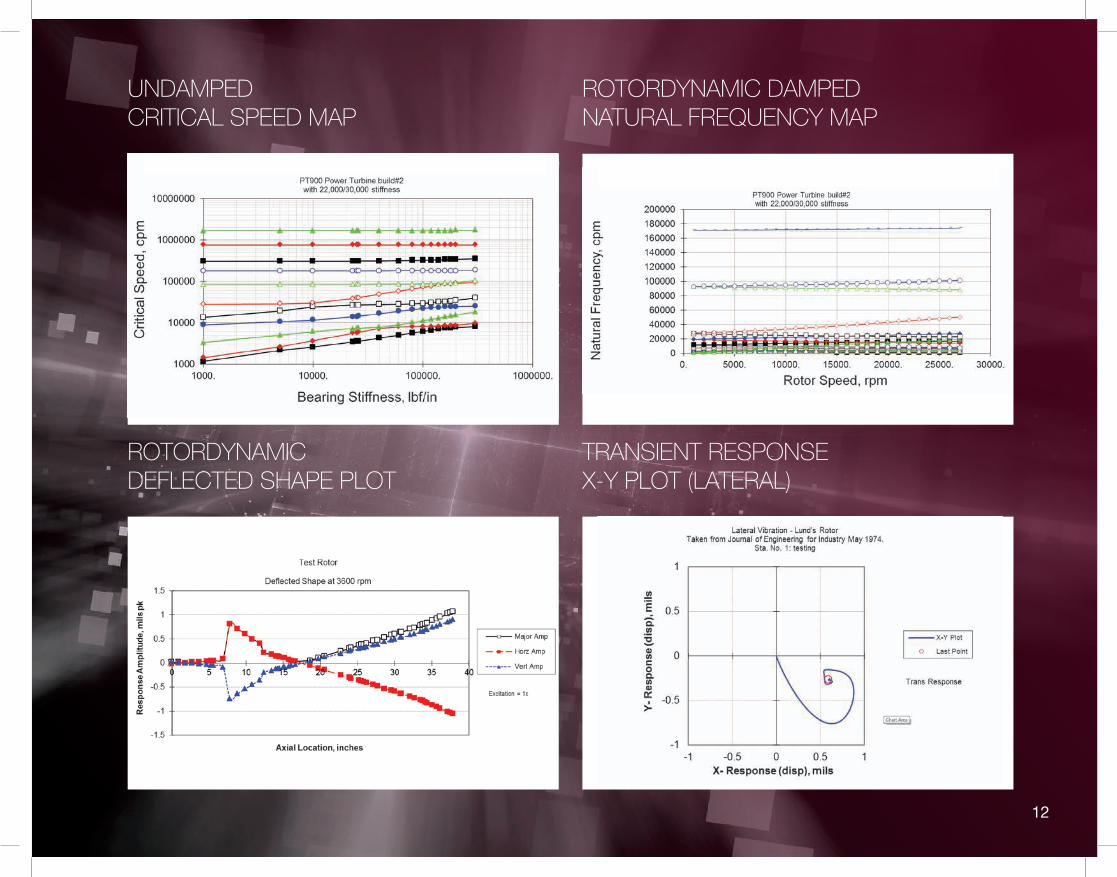
UNDAMPED CRITICAL SPEED MAP
ROTORDYNAMIC DAMPED NATURAL FREQUENCY MAP
TRANSIENT RESPONSE X-Y PLOT (LATERAL)
ROTORDYNAMIC DEFLECTED SHAPE PLOT
12
13
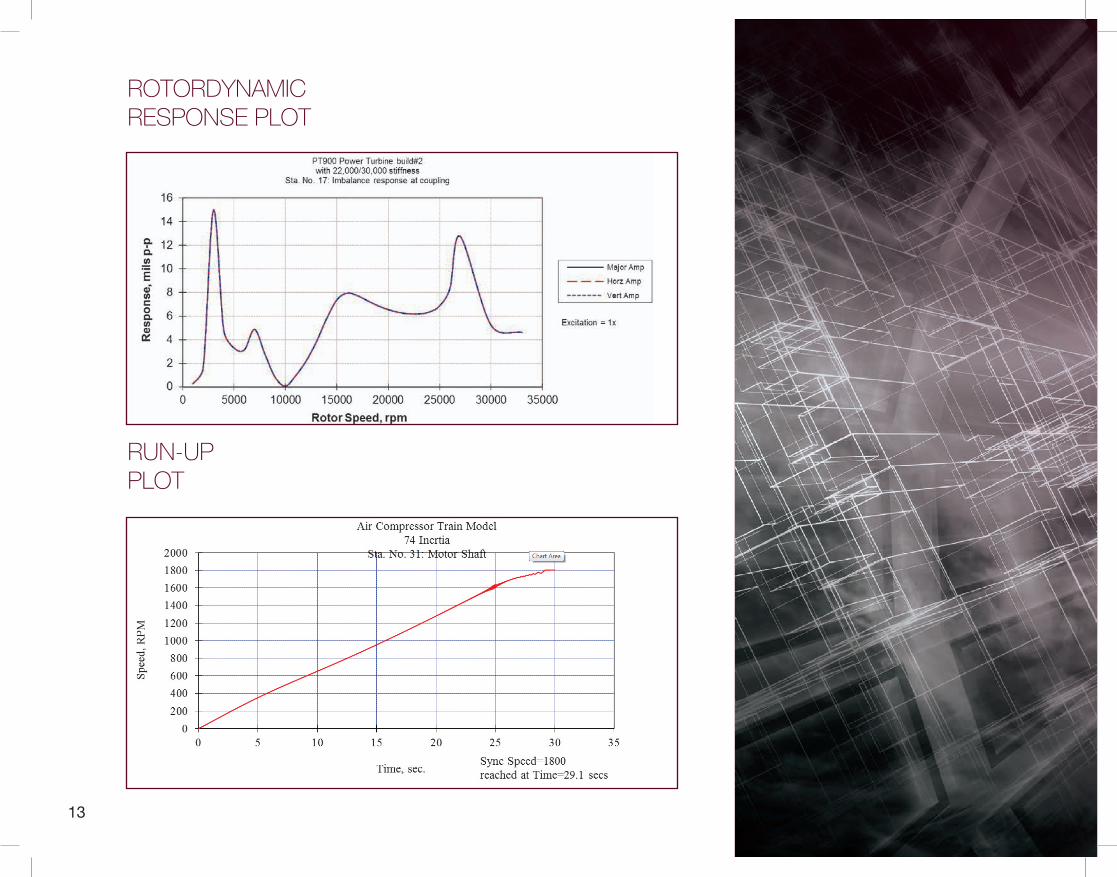
ROTORDYNAMIC RESPONSE PLOT
RUN-UP PLOT
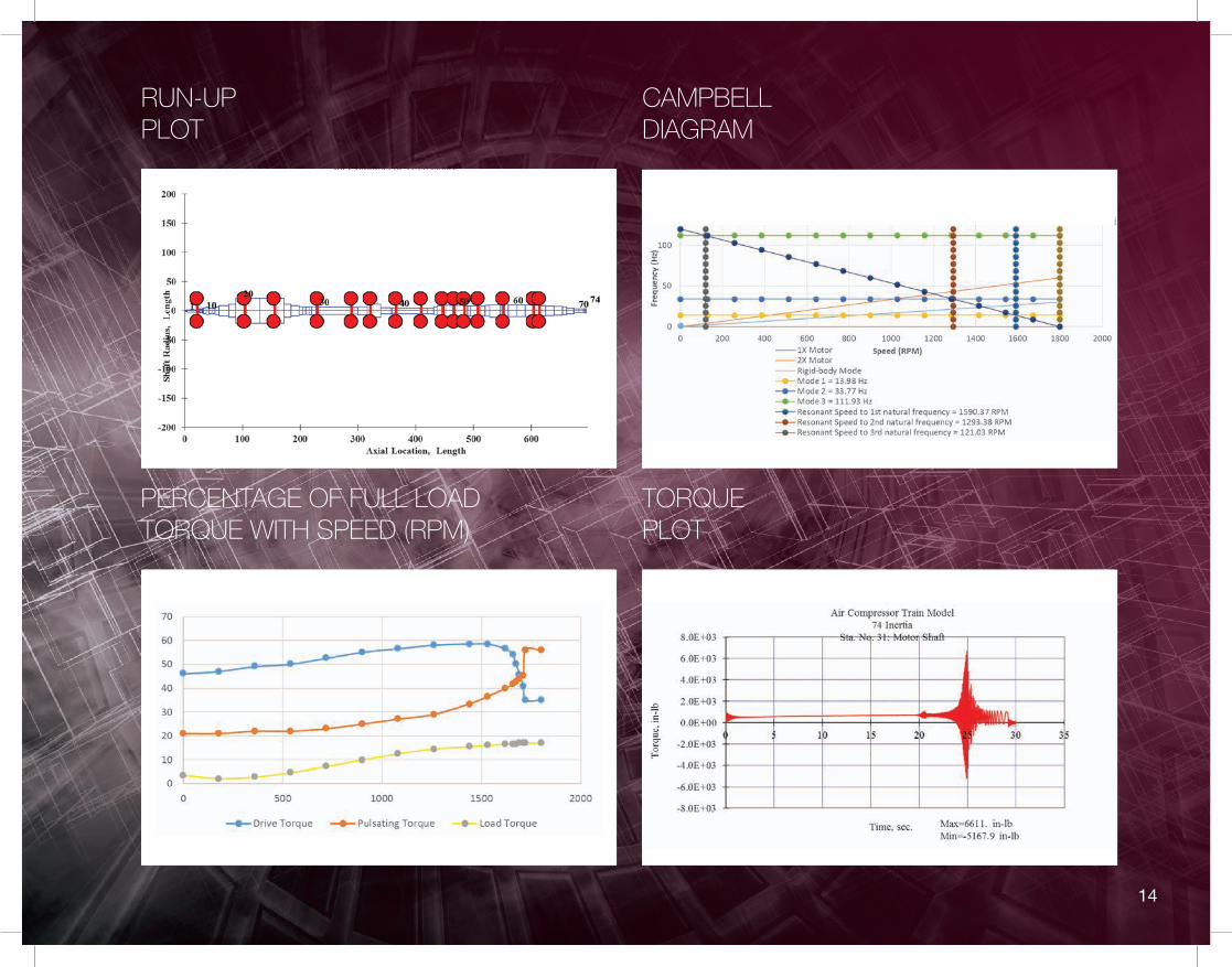
CAMPBELL DIAGRAM
TORQUE PLOT
PERCENTAGE OF FULL LOAD TORQUE WITH SPEED (RPM)
RUN-UP PLOT
14
15
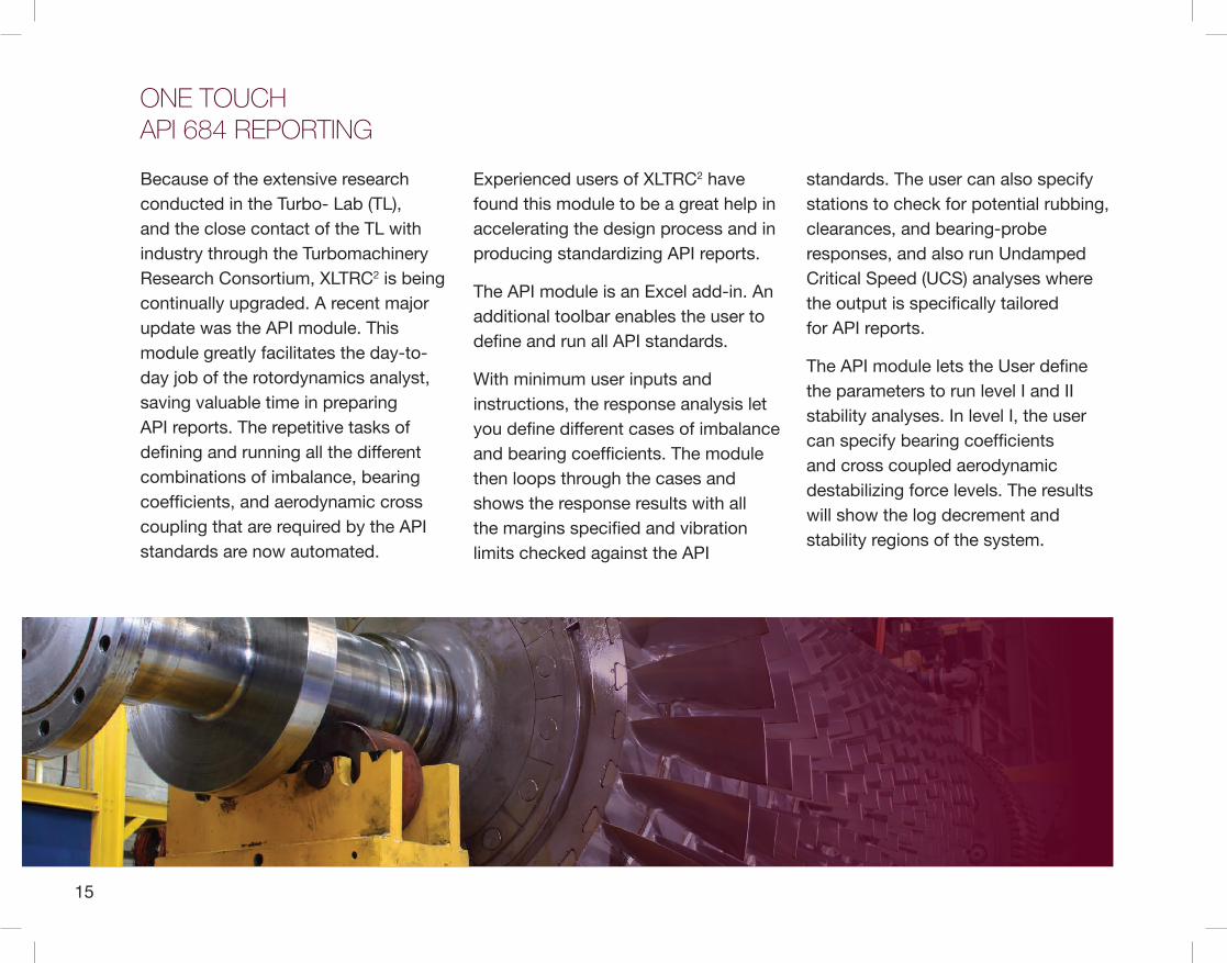
Because of the extensive research conducted in the Turbo- Lab (TL), and the close contact of the TL with industry through the Turbomachinery Research Consortium, XLTRC2 is being continually upgraded. A recent major update was the API module. This module greatly facilitates the day-to-day job of the rotordynamics analyst, saving valuable time in preparing API reports. The repetitive tasks of defining and running all the different combinations of imbalance, bearing coefficients, and aerodynamic cross coupling that are required by the API standards are now automated.
Experienced users of XLTRC2 have found this module to be a great help in accelerating the design process and in producing standardizing API reports.
The API module is an Excel add-in. An additional toolbar enables the user to define and run all API standards.
With minimum user inputs and instructions, the response analysis let you define different cases of imbalance and bearing coefficients. The module then loops through the cases and shows the response results with all the margins specified and vibration limits checked against the API
standards. The user can also specify stations to check for potential rubbing, clearances, and bearing-probe responses, and also run Undamped Critical Speed (UCS) analyses where the output is specifically tailored for API reports.
The API module lets the User define the parameters to run level I and II stability analyses. In level I, the user can specify bearing coefficients and cross coupled aerodynamic destabilizing force levels. The results will show the log decrement and stability regions of the system.
ONE TOUCH API 684 REPORTING
16
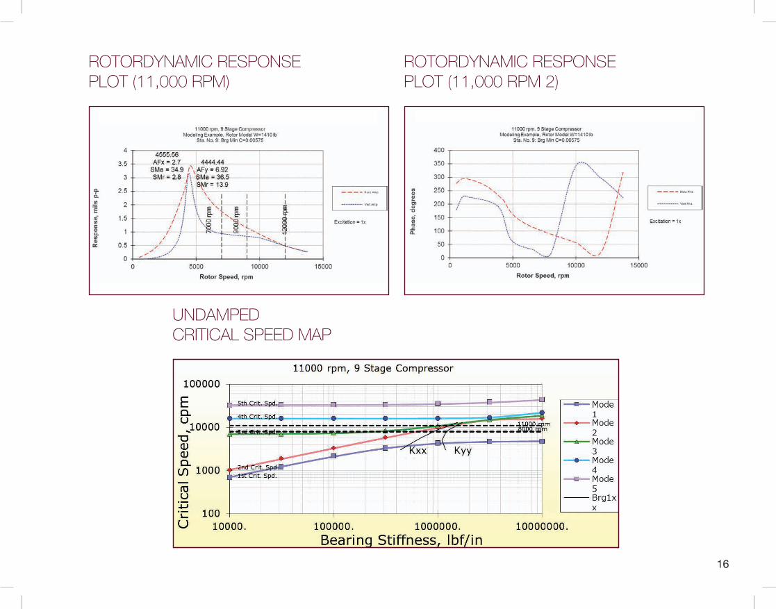
UNDAMPED CRITICAL SPEED MAP
ROTORDYNAMIC RESPONSE PLOT (11,000 RPM)
ROTORDYNAMIC RESPONSE PLOT (11,000 RPM 2)

17
The time-consuming drill of running the level II analysis is greatly automated by gradually adding all the destabilizing influences. A plot of those factors can be shown to investigate the sensitivity of log decrement to the various contributing elements.
LOG DEC X APPLIED CROSS COUPLED STIFFNESS, Q
LOG DEC X CASE
MCSR X AVERAGE GAS DENSITY
18
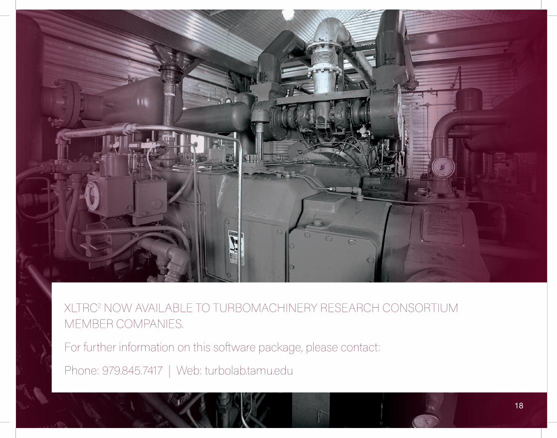
XLTRC2 NOW AVAILABLE TO TURBOMACHINERY RESEARCH CONSORTIUM MEMBER COMPANIES.
For further information on this software package, please contact:
Phone: 979.845.7417 | Web: turbolab.tamu.edu

TURBOMACHINERY LABORATORY | Texas A&M University | 3254 TAMU | College Station, Texas 77843-3254