TURBINE EFFICIENCY - Central Board Of Irrigation And...
64
Transcript of TURBINE EFFICIENCY - Central Board Of Irrigation And...

Heat Rate - concept• Common term used for indicating Power Station efficiency
• Heat rate = Heat input in Kcal / Power output in KWH
Defined : Heat required in Kcal to generate one KWH of Power

Heat Rate
UHR= TG HR/ BOILE EFFY= 2000/0.85 = 2235 kcal/kWh
NHR (Net Heat rate)= UHR /(1-apc%/100)= UHR/0.93 (Assumed APC %= 7 %)= 2235/0.93= 2403 kcal/kWh
Net Unit Thermal Efficiency= 860/2403 * 100 = 35.8 %

Efficiency and Heat Rate
• Efficiency (%) = Power generated in KWH*860* 100 / Heat Input in Kcal
= 860*100/Heat rate •Gross Turbine cycle Heat rate
Heat input to Turbine cycle in KCalGTCHR =
Power generated in KWh

Sensitive Analysis of Turbine Efficiency on Heat Rate
1 % change in HP or IP Turbine Efficiency in a 500 MW unit leads to change in HR by about
4.5 kcal/kWh and having cost implication of about Rs 57 lakhs per year (rail fed station)

• A steam turbine is a mechanical device that extracts thermal energy from pressurized steam, and converts it into useful mechanical work.

Impulse turbine Reaction turbine
Based on Compounding:
Pressure compounded
Velocity compounded
Classification
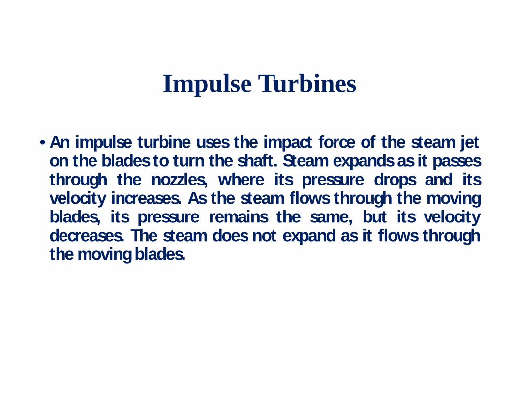
Impulse Turbines
• An impulse turbine uses the impact force of the steam jeton the blades to turn the shaft. Steam expands as it passesthrough the nozzles, where its pressure drops and itsvelocity increases. As the steam flows through the movingblades, its pressure remains the same, but its velocitydecreases. The steam does not expand as it flows throughthe moving blades.

Impulse Turbines

Velocity compounded impulse turbine

Pressure compounded

Reaction Turbines
In the reaction turbine, the rotor blades themselves arearranged to form convergent nozzles. This type of turbinemakes use of the reaction force produced as the steamaccelerates through the nozzles formed by the rotor.

Reaction Turbines

Velocity Triangles • Basic analysis of the effect of the blade rows on the steam
flow can be done through velocity triangles

Impulse- Reaction Comparison • Three significant differences (nature of the expansion process)
• Number of stages, • Bucket design, • Stage sealing requirements
• Peak efficiency is obtained in an impulse stage with more work per stage than in a reaction stage, assuming the same bucket diameter.
• Relative to an impulse turbine, a reaction turbine requiring either 40% more stages, 40% greater stage diameters, or some combination of the two to obtain the same peak efficiency.
• Reaction stage has a higher aerodynamic efficiency than an impulse stage. • Leakage losses are higher on the reaction stages • As the blade height increases, the influence of leakage losses decrease and a
point is reached where the reaction stage is more efficient

RANKINE CYCLE

1% HPT Efficiency 0.16% 0.3%
1% IPT Efficiency 0.16% 0.16%
1% LPT Efficiency 0.5 %
Output Sharing by Turbine Cylinders
210MW 500MW
HPT 28% 27%
IPT 23% 34%
LPT 49% 39%
0.5 %
Impact of Turbine Efficiency on HR/Output
Description Effect on Effect on TG HR KW
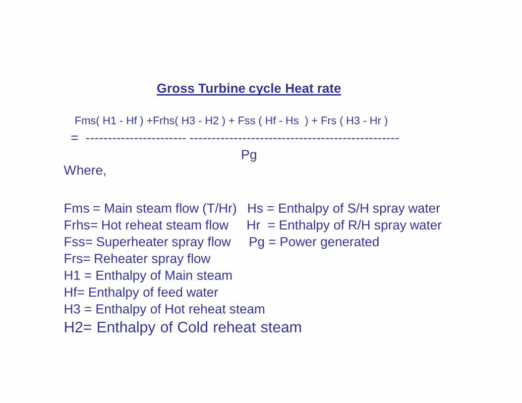
Gross Turbine cycle Heat rate
Fms( H1 - Hf ) +Frhs( H3 - H2 ) + Fss ( Hf - Hs ) + Frs ( H3 - Hr ) = ----------------------- ------------------------------------------------
PgWhere,
Fms = Main steam flow (T/Hr) Hs = Enthalpy of S/H spray water Frhs= Hot reheat steam flow Hr = Enthalpy of R/H spray water Fss= Superheater spray flow Pg = Power generated Frs= Reheater spray flow H1 = Enthalpy of Main steam Hf= Enthalpy of feed water H3 = Enthalpy of Hot reheat steam H2= Enthalpy of Cold reheat steam

Heat Added to cycle :
Heat Added MS = Flow MS * (hMS - hFW), kcal/hr
Heat Added CRH = Flow CRH* (hHRH - hCRH),kcal/hr
Heat added by SH Attemp= Flow SH Attemp* (hMS-hSHATT) Kcal/hr
Heat added by RH Attemp= Flow RH Attemp * (hHRH-hRHATT) Kcal/hr

Turbine Losses1.External Losses
2. Internal Losses
Turbine External Losses1.Shaft gland leakage Losses
2. Journal & thrust bearing losses
3.Governor & oil pump losses
Turbine Internal Losses
• Inter stage gland leakage loss
• Wetness loss
• Leaving Loss
• Exhaust loss
•Pressure drop losses
•Control valves
•Pipes

Turbine Stage Efficiency P1
P2
P3
T1
h
s
H
X YZ
W X’
Z’
Due to friction the relative velocity of steam gets reduced and hence the heat drop across the blade gets shifted from X to Z where HX is frictionless heat drop.
Stage efficiency = (Heat drop HZ / Heat drop HX) x 100 %

Turbine Cylinder efficiency
• HP cylinder efficiency
• IP cylinder efficiency

Cylinder efficiency =
Actual enthalpy drop *100/ Isentropic enthalpy drop

h
s
P1 P2P3 P5P4
P6
Saturation line
h1
h2h3h4
h5
h6h7
HP eff. =(h1-h2)*100/(h1-h4)
IP eff.=(h5-h6)*100/(h5-h7)
IP cylinder exhaust
HP exhaust

1 Gross Load 13 FW Press HPH Inlet 2 MS Pressure before ESV 14 FW Temp HPH Inlet 3 MS Temp before ESV 15 FW Press HPH Outlet 4 HPT Exhaust Pressure 16 FW Temp HPH Outlet
5 HPT Exhaust Temp. 17 Main Steam Flow (Q1) 6 HRH Steam Press. before IV 18 Feed Water Flow (Qf) 7 HRH Steam Temp. before IV 19 CRH Flow (Q2) 8 FW press after top heater 20 S/H Spray Flow (Qs) 9 FW Temp at Eco inlet 21 R/H Spray Flow (Qr) 10 HPH Ext. Steam Temp 22 S/H Spray Temp.
11 HPH Shell Pressure 23 R/H Spray Temp. 12 HPH Drip Temp 24 Leak Off Flow
Parameters required For efficiency calculation

Turbine Efficiency – Measurement Points


6 5
6 7
6 9
71
73
75
77
79
8 1
8 3
170 18 0 19 0 2 0 0 2 10 2 2 0
Gross Generator Output (MW)
HP
Turb
ine
Effic
ienc
y (%
) HP Turbine Ef f iciency at CPO (%)HP Turbine Ef f iciency at VPO (%)
Station "A" H P Turbine Efficiency vs LoadTurbine Cycle heat Rate Tests

Major energy losses in steam turbine
Blading part of flow pathNon bladed part :Inlet & Exhaust sections of turbine
casing & valvesShaft seals


OTHERS6%
SHAFT SEALS15%
INTER STAGE
27%
TIP SEALS
52%
Turbine Seals Loss break up

• Surface finish degradation:
- Deposits
- Corrosion
- Solid Particle Erosion
- Mechanical damage
• Roughness up to 0.05 mm can lead to decrease in efficiency by 4%
Turbine Surface Roughness

DIAPHRAGM
TIPSPILL STRIPS
BALANCE HOLE
WHEELPACKING
SHAFT
STEAM FLOW
ROOTSPILL STRIPS
ROTATINGBLADE
STATIONARYBLADESTAGE
PRESSURE
DOVETAIL
INTERSTAGE PACKING LEAKAGE
BALANCE HOLEFLOW
ROOT LEAKAGE
TIPLEAKAGE
COVER ORSHROUD
TENON
Impulse Wheel and Diaphragm
Construction
Seal Leakage

ROTOR
TRAILINGEDGE
BLADECARRIER
LEADINGEDGE
INTERSTAGEPACKING
TIP SPILLSTRIPS
STATIONARYBLADE
ROTATINGBLADE
TENONTIPLEAKAGE
COVER
Reaction Drum Rotor Construction
Seal Leakage

• Seal leakage is important as it is the largest singlecause of performance reduction in HP turbines.
• – Interstage seals. These include seals to preventleakage around the rotating and stationary stage.
• – End seals or packing glands are used to minimizeleakage at the ends of cylinders. They are intendedto prevent air injection into the LP and condenser
Turbine Sealing


Damaged Seals

Inter stage seals and peak seals

Diaphragm profile damage

SEALING GLANDS
• Steam is supplied to the sealing chamber at 1.03 to 1.05Kg/sq.cm abs and at temperature 130 deg.C To 150deg.C from the header.
• Air steam mixture from the last sealing chamber issucked out with the help of a special steam ejector togland steam cooler.
• Provision has been made to supply live steam at thefront sealing of H.P. and I.P. rotor to control thedifferential expansion, when rotor goes undercontraction during a trip or sharp load reduction.


Labyrinth seal

Typical Gland Seal in an HP Turbine

Rotor Shaft Area with Gland Seals Exposed

Seal Steam System

Summary of Losses
585.1
3473.0
601.3
9287.8
4486.7
47.794.00
2000
4000
6000
8000
10000
Inte
rsta
ge P
acki
ngs
Tip
Spill
Stri
ps
End
Pack
ings
Mis
cella
neou
s Le
akag
es
Flow
Pat
h D
amag
e
Flow
Cha
nge
Impa
ct
Sur
face
Rou
ghne
ss
Cov
er D
epos
its
Han
d ca
lcul
atio
ns
Trai
ling
Edge
Thi
ckne
ss
Tota
l
Pow
er L
oss
(kW
)

Followings are the reasons for error in computation of efficiency.
HPT efficiency test not done at VWO
Measurement points are not representative
Steam Turbine gas plant (Exhaust point after mixing of LP steam)
Steady conditions of Unit is not achieved.
Necessary corrections like ambient pressure, water leg not taken care
Measuring instruments are not accurate
Efficiency Assessment & Issues

HP/IP Turbine EfficiencyImpact of Measurement error on Turbine efficiency
Impact on HPT
Efficiency
Main Steam HPT Exhaust
PressureKg/cm2
TempDeg C
PressureKg/cm2
TempDeg C
1 1 1 1
0.6 % 0.6 % 2.0 % 0.7 %
Impact on IPT
Efficiency
IPT Inlet IPT Exhaust
PressureKg/cm2
TempDeg C
PressureKg/cm2
TempDeg C
1 1 1 1
1.2 % 0.3 % 6.0 % 0.4 %


FACTORS EFFECTING TURBINE EFFICIENCY
Effect of load
Terminal condition i. MS and RH P
&T ii. Effect of vacuum
Effect of heater efficiency Feed pump power

Factors affecting Turbine cycle Heat rate
• Unit Load
• Main steam temperature
• Main steam pressure
• Hot reheat temperature
• Condenser back pressure
• Final feed water temperature
• Make up water flow

• Reheater pressure drop • Superheater spray flow • Reheater spray flow • HP cylinder efficiency • IP cylinder efficiency • Generator hydrogen pressure • Grid frequency
Factors affecting Turbine cycle Heat rate

Efficiency Tests for the Assessment of Turbine Cycle Efficiency
1. Turbine Heat consumption test 2. Condenser Performance Test 3. HP Heaters Performance Test 4. Turbine Pressure Survey 5. HP / IP Cylinder Efficiency Tests 6. Estimation of Unaccounted Losses
Turbine heat consumption test • To determine the heat input into the turbine for 1 KWh of output at a particular loading. • During the test • The plant condition should be as steady as possible • RH spray flow should ideally be zero. • All the flow measurement of water and steam to be corrected for amount of in-leakage.

Turbine heat consumption test • When heat consumption at different load are plotted on a graph,
it is supposed to lie on a straight line called ‘Willans Line’. • At lower load the heat rate increases because the prominence
of fixed heat component on total heat consumption. • The slope of the curve is known as incremental heat rate.

Unaccountable Losses
High Energy drain Passing Instrument Error / Uncertainty System Water Loss L.P. Turbine Performance L.P. Heaters

High Energy Drains
Passing of High Energy drain valve affects in 3 ways
• Loss of High Energy steam
• Deterioration in Condenser Vacuum
• Damage to the valve

Methodology to reduce Unaccountable High energy drains passing
• Listing of all the drains/steam traps • Temperature mapping of drains • Action plan for repair replacement of valves • Installation of thermocouples on down stream • Progressive replacement of High energy drain valves • Attending valves during opportunity shut down. • Checking of valve of valve passing before O/H • Joint checking by Operation & TMD after unit startup

Methodology to reduce Unaccountable
Instrument Error
• Use of accurate & calibrated Instrument
System Water Loss
• D/A drop test to be conducted periodically.

THANK YOU