Tuned Collector Oscillator
3
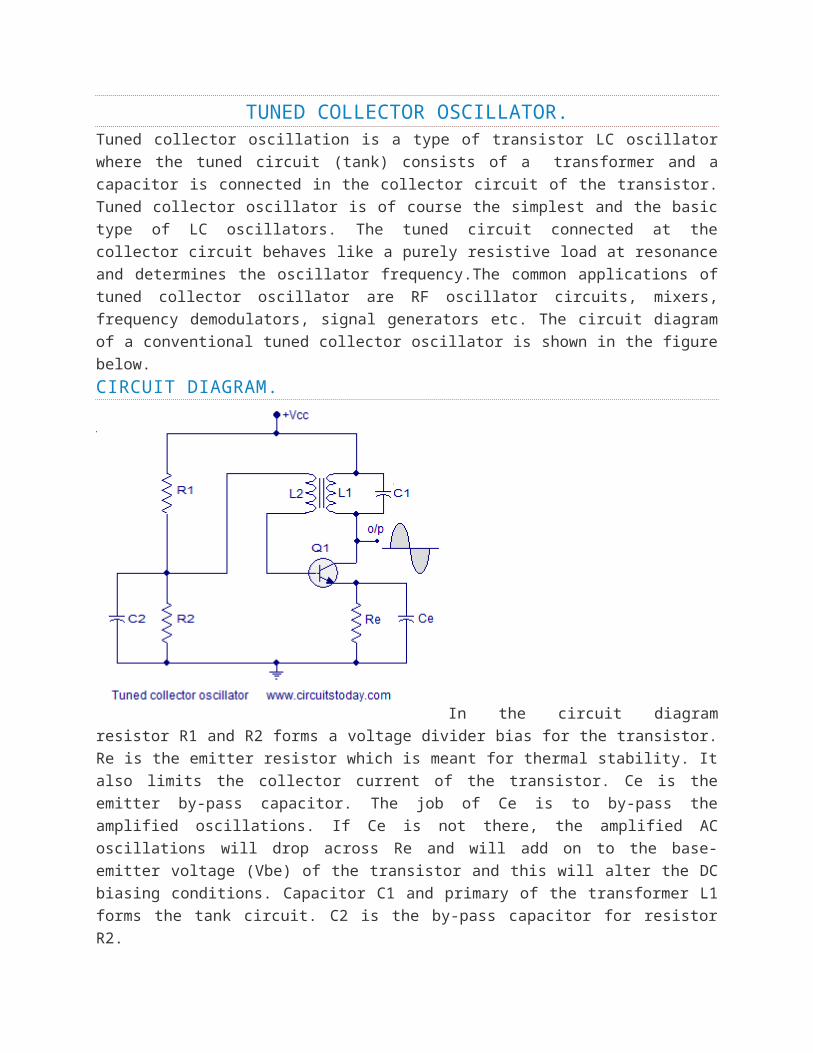
TUNED COLLECTOR OSCILLATOR. Tuned collector oscillation is a type of transistor LC oscillator where the tuned circuit (tank) consists of a transformer and a capacitor is connected in the collector circuit of the transistor. Tuned collector oscillator is of course the simplest and the basic type of LC oscillators. The tuned circuit connected at the collector circuit behaves like a purely resistive load at resonance and determines the oscillator frequency.The common applications of tuned collector oscillator are RF oscillator circuits, mixers, frequency demodulators, signal generators etc. The circuit diagram of a conventional tuned collector oscillator is shown in the figure below. CIRCUIT DIAGRAM. In the circuit diagram resistor R1 and R2 forms a voltage divider bias for the transistor. Re is the emitter resistor which is meant for thermal stability. It also limits the collector current of the transistor. Ce is the emitter by-pass capacitor. The job of Ce is to by-pass the amplified oscillations. If Ce is not there, the amplified AC oscillations will drop across Re and will add on to the base- emitter voltage (Vbe) of the transistor and this will alter the DC biasing conditions. Capacitor C1 and primary of the transformer L1 forms the tank circuit. C2 is the by-pass capacitor for resistor R2.
-
Upload
arvind-sharma -
Category
Documents
-
view
17 -
download
3
description
TUNED COLLECTOR OSCILLATOR WORKING
Transcript of Tuned Collector Oscillator
TUNED COLLECTOR OSCILLATOR.Tuned collector oscillation is a type of transistor LC oscillator where the tuned
circuit (tank) consists of a transformer and a capacitor is connected in the
collector circuit of the transistor. Tuned collector oscillator is of course the
simplest and the basic type of LC oscillators. The tuned circuit connected at the
collector circuit behaves like a purely resistive load at resonance and
determines the oscillator frequency.The common applications of tuned
collector oscillator are RF oscillator circuits, mixers, frequency demodulators,
signal generators etc. The circuit diagram of a conventional tuned collector
oscillator is shown in the figure below.
CIRCUIT DIAGRAM.
In the circuit diagram resistor R1
and R2 forms a voltage divider bias for the transistor. Re is the emitter resistor
which is meant for thermal stability. It also limits the collector current of the
transistor. Ce is the emitter by-pass capacitor. The job of Ce is to by-pass the
amplified oscillations. If Ce is not there, the amplified AC oscillations will drop
across Re and will add on to the base-emitter voltage (Vbe) of the transistor
and this will alter the DC biasing conditions. Capacitor C1 and primary of the
transformer L1 forms the tank circuit. C2 is the by-pass capacitor for resistor
R2.
WORKING OF THE TUNED COLLECTOR OSCILLATOR.When the power supply is switched ON, the transistor starts conducting and
the capacitor C1 starts charging. When the capacitor is fully charged, it starts
discharging through the primary coil L1. When the capacitor is fully

discharged, the energy stored in the capacitor as electrostatic field will be
moved to the inductor as electromagnetic field. Now there will be no more
voltage across the capacitor to keep the current through the coil starts to
collapse. In order to oppose this the coil L1 generates a back emf (by
electromagnetic induction) and this back emf charges the capacitor again.
Then capacitor discharges through the coil and the cycle is repeated. This
charging and discharging sets up a series of oscillations in the tank circuit.
The oscillations produced in the tank circuit is fed back to the base of
transistor Q1 by the secondary coil by inductive coupling. The amount of
feedback can be adjusted by varying the turns ratio of the transformer. The
winding direction of the secondary coil (L2) is in such a way that the voltage
across it will be 180° phase opposite to that of the voltage across primary (L1).
Thus the feedback circuit produces a phase shift of 180° and the transistor
alone produces a phase shift of another 180°. As a result a total phase shift of
360° is obtained between input and output and it is a very necessary condition
for positive feedback and sustained oscillations.
The collector current of the transistor compensates the energy lost in the tank
circuit. This is done by taking a small amount of voltage from the tank circuit,
amplifying it and applying it back to the tank circuit. Capacitor C1 can be made
variable in variable frequency applications.
The frequency of oscillations of the tank circuit can be expressed using the
following equation:
F = 1/[2π√(L1C1)]
Where F is the frequency of oscillation. L1 is the inductance of the transformer
primary and C1 is the capacitance.
LC OSCILLATORS SUMMARY
The basic conditions required for an LC oscillator resonant tank circuit are given as follows.
For oscillations to exist an oscillator circuit MUST contain a reactive (frequency-dependant)
component either an “Inductor”, (L) or a “Capacitor”, (C) as well as a DC power source.
In a simple inductor-capacitor, LC circuit, oscillations become damped over time due to
component and circuit losses.
Voltage amplification is required to overcome these circuit losses and provide positive gain.
The overall gain of the amplifier must be greater than one, unity.
Oscillations can be maintained by feeding back some of the output voltage to the tuned circuit
that is of the correct amplitude and in-phase, (0o).
Oscillations can only occur when the feedback is “Positive” (self-regeneration).
The overall phase shift of the circuit must be zero or 360o so that the output signal from the
feedback network will be “in-phase” with the input signal.