(T*un)0“ RÏ 9279 REPORT OF INVESTIGATIONS/1989
25
■ (T* u n) 0“ RÏ 9279 REPORT OF INVESTIGATIONS/1989 £ I Yielding Steel Posts By J, P. Dunford and L. N. Henton UNITED STATES DEPARTMENT OF THE INTERIOR BUREAU OF MINES
Transcript of (T*un)0“ RÏ 9279 REPORT OF INVESTIGATIONS/1989

■(T*un)0“ RÏ 9279 REPORT OF INVESTIGATIONS/1989
£
I
Yielding Steel Posts
By J, P. Dunford and L. N. Henton
UNITED STATES DEPARTMENT OF THE INTERIOR
BUREAU OF MINES
Mission: A s the Nat io n 's p r inc ipa l conse rva t ion agency, the Depar tment of the Inter ior has respon sibi l i t y for most of ou r n a t i o na l l y -o w ned publ ic lands and na tura l and cu l tu ra l resources. This inc ludes fos te r ing w is e use of ou r land and w a te r resources, p rotec t ing our f i sh and w i ld l i f e , p r e serv ing the env i r o n m e n ta l and cu l tu ra l va lues of ou r na t ional parks and histor i cal places, and p r o v id ing for the e n j o y m e n t of l i fe th r o u g h ou tdoor recreat ion. The D e pa r tm ent assesses our energy and minera l resources and w o rk s to assure that the i r deve lo p m e n t is in the best in te rests of al l ou r people. The D ep a r t m e n t also p rom otes the goa ls of the Take Pride in A m e r i c a c am pa ig n by encourag ing s te w a rd sh i p and ci t i zen resp ons i b i l i ty for the pub l ic lands and p r o m o t i n g c i t i zen p ar t i c ipat ion in thei r care. The D epar tm ent also has a ma jo r respons ib i l i ty for A m e r i c a n Indian res er vat ion c o m m u n i t ie s and for people w h o l ive in Island Ter r i tor ies under U.S. A dm in is t r a t io n .

Reput i of Investigations 9279
Yielding Steel Posts
By J. P. Dunford and L. N. Henton
UNITED STATES DEPARTMENT OF THE INTERIOR Manuel Lujan, Jr., Secretary
BUREAU OF MINES T S Ary, Director

Library of Congress Cataloging in Publication Data:
Dunford, J. P. (John P.)Yielding steel posts / by J. P. Dunford and L. N. Henton
(Report of investigations / United States Department of the Interior, Bureau of Mines)
Includes bibliographical references.
Supt. of Docs, no.: I 2823:9279.
1. Ground control (Mining). 2. Columns, Iron and steel. I. Henton, L. N. (Laurin N. ). II. Title. III. Series: Report of investigations (United States. Bureau of Mines); 9279.
TN23.U43 [TN288] 622 s-dc20 [622’.28] 89-600164

Abstract...................................................................................................................................................................................... 1Introduction.............................................................................................................................................................................. 2Approach ..................................... .. ..................................................................................................... .................................... 3
Post design ........................................................... ................................................ ..................... ...................................... 3Laboratory evaluation........................................................................................................................................................ 3Fabrication of yielding steel p o s t ...................................................................................................................................... 6Field tr ia ls ............................................................................................................................................................................ 6
Trial 1 .................................................................................................................................... .. 6Trial 2 ................................................................................... .......................................................................................... 7
Conclusions .............................................................................................................................................................................. 12Appendix A,-Calculations and assumptions for economic comparison...................................................................... 13Appendix B.-Equations of tube expansions....................................................................................................................... 14
ILLUSTRATIONS
1. Yielding steel p o s t ...................................................................................................................................... .. 22. Radial deformation of yielding steel post ...... ......................................................................................................... 23. Load deflection curves for various amounts of ring interference......................................................................... 44. Compression tests, greased versus ungreased ......................................................................................................... 55. Test entry, two-rail system ........................................................................................................................................... 86. Test entry, one-rail system . . . . . . . . . . . . . . . . . . . . . . . . . . . . . . . . . . . . . . . . . . . . . . . . . . . . . . . . . . 97. Monitoring load buildup on yielding steel post .................................................. ................................................... 108. Transition from two-rail system to one-rail system ............................................................................................... 109. Pipe splitting problem .................................................................................................................................................. 11
B-l. Flow of material through conical die ..................... ................................................................................................. 14B-2. Kinematically admissable velocity field ..................................................................................................................... 14B-3. Spherical coordinates.................................................................................................................................................... 15B-4. Geometry of tube expansion ...................................................................................................................................... 18
CONTENTSrage

UNIT OF MEASURE ABBREVIATIONS USED IN THIS REPORT
ft foot Ibf pound (force)
in inch min minute
lb pound (mass)

YIELDING STEEL POSTS
By J. P. Dunford1 and L N. Henton1
ABSTRACT
This U.S. Bureau of Mines report describes the development of a yielding steel post for underground mine support. T h e report covers concept development, laboratory tests, modifications, and field evaluations.
The objective of this work was to develop a stiff support member capable both of supporting high loads and yielding when excessive am ounts of mine entry closure were present. The 6- to 7-ft steel post was designed to yield nearly 2 ft while maintaining a 45-ton (force) load. The post is a three-piece unit consisting of top and bottom telescoping legs and a separate foot bracket. It develops its load-carrying characteristics when the lower pipe, with an attached interference ring, is forced into the larger top pipe.
Laboratory tests were used to determine critical loads and post performance for various post lengths. Field tests showed that the posts could perform in actual mining conditions. The post has the ability to provide support in highly yielding ground and also, because of its slender profile, enhance ventilation and provide more area for travelways and escapeways. The design is simple enough to allow for fabrication at most mine shop facilities.
'Mining engineer, Spokane R esearch Center, U. S. Bureau of Mines, Spokane, WA.
2
INTRODUCTION
A problem in underg round m ining is stabilization of excavations in highly yielding rock m asses. A fter an excavation is m ade, the su rrounding stra ta m ay be displaced into the entry, causing rib slough, roo f sag, and floor heave. T his d isp lacem ent reduces the area available for ventilation, travelways, and escapeways.
E n tries used in re tre a t longwall m ining typically are subjected to th ree different stages of loading: w hen the entry is initially developed for use as a headgate, w hen the longwall face re trea ts along the en try during its use as a headgate, and w hen the adjacent longwall panel is m ined and the en try is used as the tailgate. T he tailgate m ust then be m ain ta ined after m ining is com pleted for ventilation and as an escapeway.
C urrently , m ost artificial roo f supports in coal m ines consist o f roo f bolts, w ooden posts and cribs, and concrete cribs. W ood supports a re readily available, easy to handle, and a re inexpensive com pared to steel and concrete supports. W ood has som e disadvantages, however.
1. A lthough w ood is very strong w hen loaded parallel to the grain, its strain capacity is lim ited; conversely, when loaded perpend icu lar to the grain, wood has a be tte r strain capacity but it is m uch w eaker.
2. T he streng th of w ood can vary significantly with each individual piece, w ith th e result being tha t a structu re m ade from wood, such as a crib, is only as strong as its w eakest part.
3. T he bulkiness of w ooden cribs and posts reduces the am ount of air flow.
4. W ood is a flam m able m ateria l and can prom ote m ine fires.
5. W ood is susceptib le to decay.
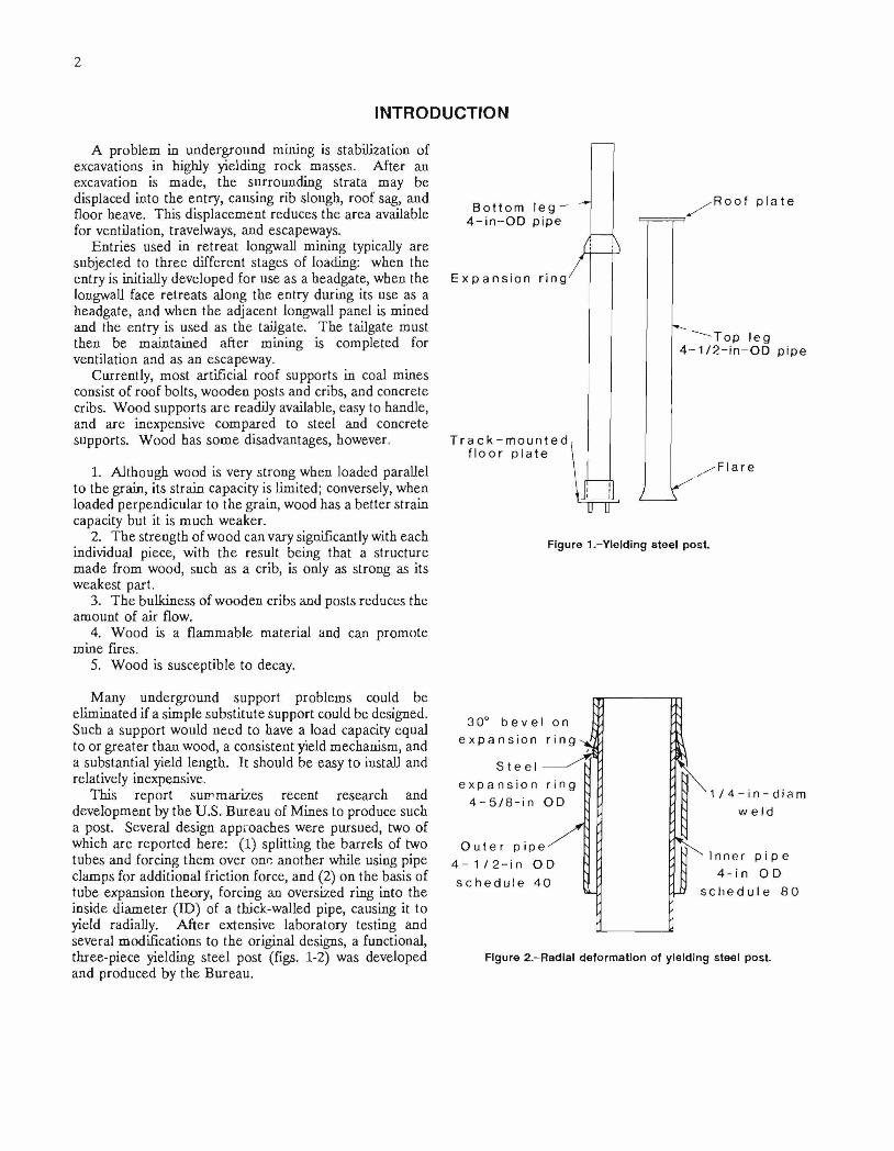
B o t t o m l e g - 4 - m - O D p ipe
E x p a n s i o n r i n g 7
- R o o f p l a t e
T r a c k - m o u n t e d f l o o r p l a t e
op le g 4 - 1 / 2 - i n - O D p ipe
- F l a r e
Figure 1.-Yielding steel post.
M any underground support p rob lem s could be elim inated if a sim ple substitu te support could be designed. Such a support w ould need to have a load capacity equal to or g rea te r than wood, a consistent yield m echanism , and a substantial yield length. It should be easy to install and relatively inexpensive.
T his rep o rt sum m arizes recent research and developm ent by the U .S. B ureau of M ines to produce such a post. Several design app roaches w ere pursued, two of which are rep o rted here: (1) splitting the barre ls of two tubes and forcing them over one ano ther while using pipe clam ps for additional friction force, and (2) on the basis of tube expansion theory, forcing an oversized ring into the inside d iam eter (ID ) of a thick-walled pipe, causing it to yield radially. A fter extensive laboratory testing and several m odifications to the original designs, a functional, th ree-p iece yielding steel post (figs. 1-2) was developed and produced by the B ureau .
' 1 / 4 - i n - d i a m weld
I nn e r p i p e 4 - i n O D
c h e d ul e 8 0
Figure 2.-Radlal deformation of yielding steel post.

3
APPROACH
Before a prelim inary design could be made, it was necessary to determine the requirements for a support that could be used in highly yielding ground. After such design requirements were established, prototypes were built and tested in the laboratory. Modifications were made on the basis of the test results until a working prototype was developed.
The design was based on a com bination of performance, ease of fabricating and handling, and economic considerations. Performance of the wood and steel supports currently used for column-type supports were analyzed. Factors such as typical mine roof and floor compressive strengths and displacements, average longwall m ining heights for Western coal mines, and overburden thicknesses were taken into account.
Ease of handling was also an important design consideration. The weight of the supports was restricted to what could normally be lifted by one individual. Special installation equipment was to be avoided because of added cost and the lack of working space in an entry.
Cost of the new support system was an important criterion. Wood and concrete crib support systems were compared with yielding steel posts in terms of m aterial cost, fabrication cost, and shipment to and installation in the mine. The assumptions and calculations used to make these comparisons are given in appendix A.
A market survey was conducted to determine if similar supports were already being manufactured, especially supports with high-capacity and high-yield features. It was found that one manufacturer does produce a support using a design similar to the yielding arch concept. This type of support develops load resistance from the sliding friction between clamped legs. A number of supports were tested but they did not meet design specifications; that is, they lacked the load capacity and yield characteristics desired.
After the design requirements were established, appropriate materials were selected and the yield mechanism was developed. Wood, steel, concrete, and composite materials w ere evaluated, and steel was chosen because of its availability, high strength, nonflam m ability, and relatively low cost.
Design requirements for the new support were as follows:
1. The mechanism must have at least a 50-ton2 capacity, based upon the average strength of a 6- to 8-indiameter wood post.
2. It must maintain a controlled closure up to 6 in, which is acceptable in a coal seam greater than 60 in.
3. It should be as slender as possible, to prevent interference with ventilation.
4. It should be easy to manufacture, ideally in a mine shop.
2In this report, "tons" refers to tons of force (2,000 Ibf).
5. Operation should be simple, reducing the risk of poor installation,
6. It should be easy to install, reducing injuries and cost.
7. It should cost less than $200 to manufacture.
POST DESIGN
The first designs tested utilized the clamp-and-sliding- friction concept for developing load characteristics. It was found that loading was a function of both the number of bolts used and the torque applied to the bolts. To obtain the 50-ton design lim it, more than ten 3/4-in bolts (five clamps) were used without much success.
At this point a decision was made to utilize the physical properties and geometry of steel pipe. In the first attempt, a series of slots was cut into a pipe. This pipe was then forced into a second, slightly larger pipe, causing friction and deformation of the first (slotted) pipe, which in turn created load resistance. Results were inconsistent and the design did not allow for large amounts of yield. However, deformation of the outer pipe observed during testing led to the concept of producing load resistance by deliberately causing the outer pipe to yield.
To develop the loads required to deform a steel pipe, a weld bead was applied around the outside circumference of the smaller pipe. The increase in diameter on the inner pipe caused interference when the pipes w ere forced together. This worked better and had much more potential for yield, but again, the load capacity at the yield point was inconsistent.
The most successful design tested consisted of an expansion (interference) ring welded to the outside surface of the smaller pipe. The two pipes were then forced together until the ring caused the larger pipe to deform radially (fig. 2). This behavior is similar to that occurring in the extrusion process for manufacturing seamless pipe.
LABORATORY EVALUATION
When initial testing and theory indicated that the interference mechanism would generate a controlled, predictable yield in the laboratory, additional performance characteristics representing the loads, loading patterns, and support height requirements of actual mining conditions needed to be developed. Using the initial design criteria and information obtained from several Western mines concerning gate road entries and ground response during longwall mining, the following support requirements were set:
1. The upper height lim it for the support prototype would be 84 in.
2. The weight w ould not exceed 120 lb for the total support.

4
3. T he support should have a capacity of 45 to 50 tons.34. T he support should be capable of yielding up to 24
in.Initial testing indicated that to obtain the requ ired load
capacity and yield characteristics prior to buckling, the pipe colum n m ust be 3 to 4 in. in d iam eter and have walls betw een 1 /4 and 1 /2 in thick. In addition, to develop a 40- to 50-ton capacity, an in te rference of at least 1 /2 in is required . F or econom ic and availability reasons, 4-in, ASTM -120, schedule 40 seam ed pipe was selected for the top (yielding) leg and 3-1 /2-in , A STM A-120, schedule 80 pipe was used for the bo ttom (force) leg. T he expansion ring m aterial was cut from 4-3/4-in cylindrical tube stock. This created a tight fit with the 3-1 /2-in pipe and produced better alignm ent during the welding process.
T he p ro to type design consisted of a top leg with a flared end and a bo ttom leg with an expansion ring that had been lathed to a p redeterm ined outside d iam eter (O D ). T o determ ine w hat O D was required , early testing indicated that d im ensions o f the top leg ID w ere critical. T he ID of A STM A -120 pipe does not have to conform to strict specifications; discrepancies in excess o f 0.010 in are com m on and som e as large as 0.075 in have been m easured. T h erefo re it was critical to the perform ance of the unit to first m easu re the pipe ID and then lathe the expansion ring to a specific O D so that the p redeterm ined in terference was correct.
3Bowers, E. T., and L . N. H enton. A Sum m ary of D ata From the Sunnyside Single E ntry Study-1971-80. BuM ines O F R 25-84, 1983, 541 pp.
A lthough the ring yield m echanism w orked well in the initial tests, the posts them selves buckled and failed. The jo in t in the m iddle of the colum n added eccentricity to the colum n, which prom oted buckling failure. Several changes w ere m ade in the design to p roduce an acceptab le load- yield curve w ithout buckling. T he size and shape of the in terference ring w ere specified, and a bevel was added to the leading edge of the in te rference ring to elim inate the plowing action of the previously sharp edge. (Originally, the 90° angle at the upper edge of the expansion ring would becom e em bedded in the larger pipe and cause gouging of the m etal, thus leading to buckling of the post.) A dditional testing show ed that the bevel and a m inim um of 0.5 in of in terference betw een the ID of the larger pipe and the O D of the in te rference ring resulted in an acceptable load curve and a sm ooth yielding process (fig. 3).
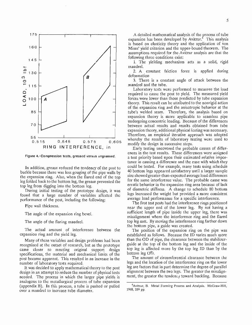
D uring the testing, heavy grease was applied to som e of the units, and although the general sh ap e of the loading curve did not change, this low ered the load value that could be obtained with a given in terference. F o r example, for a post having an in terference of 0.545 in and no grease, a 55-ton load couJd be achieved befo re the pipe buckled, but by using the sam e in terference and adding grease, only a 45-ton load could be developed.
F u rthe r testing show ed tha t by increasing the in terference and greasing the ring, higher loads could be ob tained with less likelihood of buckling. In several cases, in terferences g rea ter than 0.565 in w ere used and loads g rea te r thaxi 65 tons w ere achieved (fig. 4).
KEYt e r f e r e n c e r ing - ID o f t o p leg
= 0 . 5 6 3 in
= 0 . 5 6 4 in
= 0 . 5 6 5 in
= 0 . 5 6 6 in
4 5 6 7 8 9 10
DEFLECTION, in
Figure 3.-Load deflection curves for various amounts of ring interference.
5
0 . 5 1 5 0 . 5 4 5 0 . 5 7 5 0 . 6 0 5R I N G I N T E R F E R E N C E , in
Figure 4.~Compression tests, greased versus ungreased.
In addition, g rease reduced the tendency of the post to buckle because th e re was less gouging of the pipe walls by the expansion ring. A lso , when the flared end of the top leg folded back to the bo ttom leg, the grease prevented the top leg from digging into the bottom leg.
D uring initial testing of the prototype design, it was found that a large n u m ber of variables affected the p erfo rm ance of the post, including the following:
P ipe wall thickness.
T he angle of the expansion ring bevel.
T he angle of the flaring m andrel.
T he actual am ount of in te rference betw een the expansion ring and the yield leg.
M any of these variables and design problem s had been recognized at the outset o f research , but as the prototype cam e closer to m eeting original support design specifications, the m ateria l and m echanical lim its of the post becam e apparen t. T his resu lted in an increase in the num ber of labora to ry tests required .
It was decided to apply m athem atical theory to the post design in an a ttem p t to reduce the num ber of physical tests needed. T h e process in which the larger p ipe yields is analogous to the m etallurgical process of tube expansion (appendix B). In this process, a tube is pushed or pulled over a m andrel to increase tube d iam eter.
A detailed m athem atical analysis of the process of tube expansion has been developed by A vitzur. This analysis is based on elasticity theory and the application of von M ises’ yield criterion and the upper-bound theorem . T he assum ptions requ ired for the A vitzur analysis are that the following th ree conditions exist:
1. T he yielding m echanism acts as a solid, rigid m andrel.
2. A constant friction force is applied during deform ation
3. T h ere is a constant angle of attack betw een the m andrel and the tube.
L aboratory tests w ere perfo rm ed to m easure the load requ ired to cause the post to yield. T he m easured yield forces w ere lower than those p red ic ted by tube expansion theory. This result can be a ttribu ted to the nonrigid action of the expansion ring and the anisotropic behavior at the tu b e’s w elded seam . T herefo re , the analysis based on expansion theory is m ore applicable to seam less pipe undergoing concentric loading. B ecause of the differences betw een actual results and results ob tained from tube expansion theory, additional physical testing was necessary. T herefo re , an em pirical iterative approach was adopted w hereby the results of labora to ry testing w ere used to modify the design in successive steps.
E arly testing uncovered the p robab le causes of differences in the test results. T hese differences w ere assigned a test priority based upon their es tim ated relative im portance in causing a d ifference and the ease with which they could be tested . F o r exam ple, m any tests using schedule 40 bo ttom legs appeared satisfactory until a larger sam ple size show ed g reater-than-expected average load differences for the sam e in terference value. T h e p robab le cause was erra tic behavior in the expansion ring area because of lack of d iam etric stiffness. A change to schedule 80 bottom legs increased the weight but provided a m ore consistent average load perform ance for a specific interference.
T he first test posts had the in te rference rings positioned near the upper end of the lower leg. By not having a sufficient length of p ipe inside the upper leg, th e re was m isalignm ent w here the in te rfe rence ring and the flared top leg m et. By m oving the in te rfe rence ring farther down the bottom pipe, a guide was created .
T he position of the expansion ring on the pipe was established as follows. B ecause the ID varies m uch m ore than the O D of pipe, the clearance betw een the stabilizer- guide at the top of the bottom leg and the inside of the top leg is affected m ore by the top leg ID than by the bottom leg OD.
T he am ount o f circum ferential clearance betw een the legs and the location of the in te rference ring on the lower leg are factors that in part determ ine the degree of parallel alignm ent betw een the two legs. T he g rea ter the m isalignm ent, the g rea ter the tendency tow ard buckling. Because
4Avitzur, B. M etal Form ing Process and Analysis. McGraw-Hill, 1968, 339 pp.
6
of the variation in clearances in different lots of pipe and also because of differences in the heights of the weld beads inside the top legs, the interference ring was located 16 in from the top after a location of 8 in from the top failed to provide acceptable results. Ideally, the interference ring should be placed at greater than one-half the top leg height, but this was precluded by the desired 70-in minimum height and 24-in convergence range.
To prevent the top of the bottom leg from gouging the inner wall of the top leg when the post was being loaded, the top 0.25 m of the bottom leg was beveled to approximately 8°. If the bottom leg locks because of gouging, the top leg will buckle. The bevel at the top of the bottom leg automatically becomes lubricated as it picks up grease from the inside of the top leg, which then prevents further locking and buckling.
To operate this support, enough clearance was needed to be able to easily fit the two legs together into starting position by hand. Hand-fitting was always possible using ASTM A-120 pipe, but more expensive pipe could not be fitted together by hand without lathing the bottom leg OD smaller than stock. The ID of the lowest priced seamless pipe was more often out-of-round, or oval shaped, than the least expensive ASTM A-120 pipe.
FABRICATION OF YIELDING STEEL POST
The test results led to the development of a functional post design that could be used in highly yielding ground conditions. The post was made from ordinary ASTM A- 120 pipe, mild steel plate (for the roof and floor plates), and cylindrical tube stock (for the expansion ring). Materials were purchased precut to standard dimensions. The bottom mounting bracket was constructed by welding the flat plate to a short section of pipe (fig. 1). The roof plate was welded to the top leg in a similar manner.
Easy and consistent entry of the bottom leg into the top leg required a 30° flare on the bottom end of the top leg. A greased mandrel was used to start the flaring at a load of about 12.5 tons and to finish at 30 to 37.5 tons. Flaring stopped when the pipe end reached an OD of 5.125 to 5.25 in. Greater flaring promoted splitting at the open end.
The expansion ring was cut from the cylindrical tube stock to the correct length of 0.5 in. The ring was then welded around the pipe on both the top and bottom of the ring to ensure maximum strength. The top leg ID was then measured. The amount of interference was previously calculated based on the design load of the unit.
With the upper leg ID known, the expansion ring was then lathed to the proper OD to produce the correct interference. Grease was then added to the top leg.
FIELD TRIALS
The objective of the field trials was to place the units in a working mine under actual operating conditions. In a mine, the posts could be loaded by a sudden impact, which would be quite a different situation from controlled loading by laboratory equipment
The field test criteria required that the test site have high vertical loads and a large amount of roof-to-floor closure. A Western coal mine with 1,500 to 2,500 ft of overburden in a retreat longwall section met these specifications. At this mine, gate roads are used twice during their lifetime: first as the headgate and then as thetailgate for the adjacent panel. To reduce entry closure, the operator must install double and triple rows of cribs. Even with massive cribbing, there is still a great deal of floor heave between the cribs.
Mine management cooperated with the Bureau by providing advance information concerning the test site and a mine crew to both install the posts and monitor the site visually when Bureau personnel were not present. The mine also obtained the Mine Safety and Health Administration (MSHA) permit required for an experimental support system. The Bureau provided the yielding posts, and Bureau personnel mapped and measured the test site area, coordinated the installation, and retrieved test site data after the posts were installed.
The yielding posts were placed in two test sections. In the first section, 10 posts were installed alongside the wooden crib line. The success of this test and discussions with mine management led to a larger scale second test, where 84 yielding steel posts were placed in two different configurations along 187 ft of headgate entry. Both field tests are described in detail in the following sections.
Trial 1
Ten prototype units were built. The posts were designed to be used in a seam 72 to 84 in high. They had a total potential yield of 23 in, a load capacity of 50 tons, and a weight of 112 lb. In the summer of 1984, these units were installed as supplemental support in the tailgate of the mine over a 90-ft-long entry and 400 ft from the starting point of the longwall. (The mine designation for the longwall panel where the posts were installed is 17th right.)

7
At the time of installation., the com pany was having grea t difficulty m aintain ing airflow and escapeway clearance th rough the longwall entries. The 16th right longwall panel had a history of extreme floor heave. In the 16th right panel, the floor heave followed the longwall from 0 to 300 ft behind the face while the entry was used as a headgate. Additional floor heaving occurred while the entries were used as a tailgate. S om etim es this abutment load appeared as much as 50 ft ahead of the longwall face. Total floor heave was often as much as 24 in and pieces of fractured floor would be standing almost vertically in the entry.
As the longwall face proceeded past the test area, ail of the posts yielded between 1 and 3 in. Five of the posts had significant yield, indicating that the 50-ton design load had been exceeded. One of these five supports did buckle, leading to the conclusion that the post load capacity should be reduced. After reviewing the laboratory test data, it was felt that a 10% reduction in load capacity (5 tons) would ensure column stability. Furthermore, the 7-insquare top bearing plates proved to be too small. After the longwall passed the area and the ground was highly fractured, the roof fell out around the plate so that eventually the post was only supporting a small column of overlying strata.
Trial 2
After the first field test demonstrated the ability of the post to load quickly and to yield without failing, mine management agreed to a more extensive test of the yielding steel posts. While monitoring the performance of the posts in the first test section, two observations were made that affected post installation in the second test area. First, even though the crib lines were installed close to one another (8-ft centers), the floor would heave between the cribs, causing a reduction in roadway height and in the
area of cross section available for ventilation; secondly, track rails used during development of the entries were available for use with the post support system.
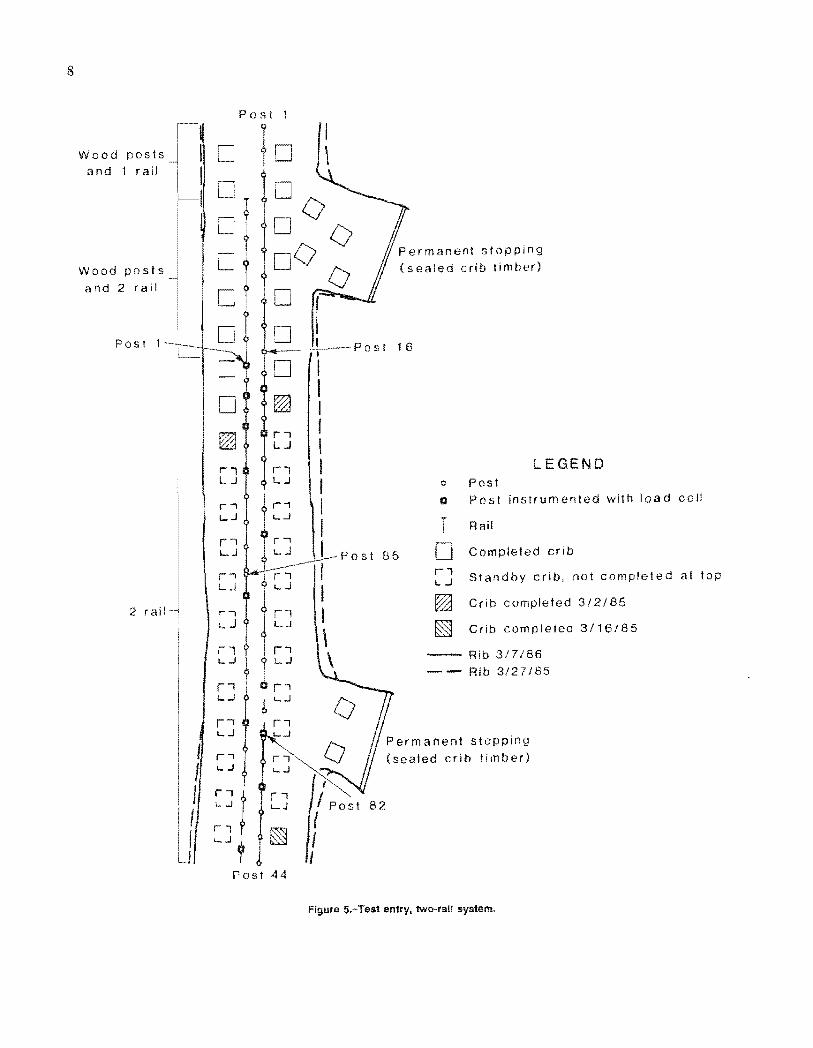
After discussing the possible use of the rails during the second field test, the continuous-floor-beam approach was conceived. This approach called for installing yielding steel posts on salvaged track rail. One configuration had two parallel rails down the center of the entry; the posts were mounted every 5 ft on each rail, with an offset of 2.5 ft between the two rails, resulting in a yielding steel post being placed every 2.5 ft (fig. 5). The second configuration had a single rail centered in the entry and a yielding post mounted every 2.5 ft (figs. 5 and 6).
P rio r to this test, wooden posts and a center crib line were used with poor results. It was hoped that a continuous-floor-beam yielding support would provide improved support during entry use as both a headgate for the 17th right longwall and subsequently as a tailgate for the 18th right panel. The spacing in the one- and two-rail systems was determined to have the same support characteristics as the wood crib configuration currently being used.
Eighty-six yielding steel posts w ere fabricated for the second test. Eighty-four were installed and two were reserved for replacement if necessary. With 1,500 ft of cover in the trial site area, loads of 12 tons per linear foot were expected. Twenty-one flat hydraulic stress cells were installed on the posts to measure loads (fig. 7). Based on information from the first trial, the amount of interference between the expansion ring on the inner pipe and the ID of the outer pipe decreased. This lowered the yield load capacity from 50 to 45 tons and thus decreased the possibility of column buckling. A 12-in-square plate was used for a roof plate to increase the load-bearing area. The bottom mounting plate was modified to fit over the track (fig. 8). This included welding flanges on each side for stability.
W o o d p o s t s a n d 1 r a i l
W o o d p o s t s a n d 2 r ai l
P o s t 1 —
2 r a i l
P o s t 1
P e r m a n e n t s t o p p i n g ( s e a l e d c r i b t i mbe r )
LEGENDo Pos tQ P o s t i n s t r u m e n t e d w i t h l o a d c e l l
f Rai l
| | C o m p l e t e d c r i b
S t a n d b y c r i b , no t c o m p l e t e d at t op
C r i b c o m p l e t e d 3 / 2 / 8 5
C r i b c o m p l e t e d 3 / 1 6 / 0 5
r iL J
Rib 3 / 7 / 8 6 R ib 3 / 2 7 / 8 5
P e r m a n e n t s t o p p i n g ( s e a t e d c r i b t i m b e r )
P o s t 4 4
Figure 5.-Test entry, two-rail system.

D e l e t e d
8 0
9
P o s t 44
1 rai l
l o c a t i o n s _
- 8 5
2 r a i l -
LEGENDPostP o s t i n s t r u m e n t e d w i t h l o a d c e l l
R a i l
C o m p l e t e d c r i b
S t a n d b y c r i b , no t c o m p l e t e d a t t o p
C r i b c o m p l e t e d 3 / 1 6 / 8 5
C r i b c o m p l e t e d 3 / 2 2 / 8 5
C r i b c o m p l e t e d 3 / 2 3 / 8 5
C r i b c o m p l e t e d 3 / 2 5 / 8 5
R ib 3 / 7 / 8 5 R i b 3 / 2 7 / 8 5
P e r m a n e n t s t o p p i n g ( s e a l e d c r i b t i m b e r )
Figure 6 .-Test entry, one-rail system.

IO
Figure 7.-MonItorlng load buildup on yielding steel post.
Figure 8.-Transltion from two-raii system to one-rail system.

11
At the tim e of this test, a m inim um of two and som etim es th ree rows of cribs with posts had been required to support th e entries. Both M SH A and m ine m anagem ent thought it p rudent to build the two outside rows of cribs in the test entry, but they did not plan to preload the cribs with wedges until the steel posts and rails showed inadequate suppo rt capability. D uring the first m onth after installation, loads of 10 tons per linear foot w ere m easured on the posts. A fter 6 m onths, the average load on the posts was nearly 12 tons. This 12-ton load agrees with the average load m easured by W hittaker5 under sim ilar conditions in the U nited Kingdom.
T h ere w ere som e problem s in this field test, mainly because of differences in pipe quality. It was noted that som e of the m anufactu red pipe in the 86 test units had slightly th inner walls than pipe purchased earlier. H ow ever, wall thickness was stiil w ithin the specifications for A ST M A-120 seam ed pipe. D uring the flaring operation , som e of the pipe split at the weld. P rio r to this test, no top legs had split in over 100 flaring operations. R ew elding the split provided enough additional strength to reflare the units. T he posts m ade with the inferior pipe w ere m arked to see how they would perform in the field. A fter 1 m onth underground , the splitting problem occurred again (fig. 9).
T he m ine op era to r decided to com plete installation of the cribs in the test a rea after 2.5 m onths. T he test site stabilized after the longwall had passed. A followup inspection of the site found that 10 to 20 in of closure w ere
•’Whittaker, P. E. Strata Loading in Mine Roadway Supports. Min. Sci. and Tcchnol., v. 2, No. 1, 1984, pp. 45-46.
com m on; however, the section supported with the yielding steel posts was m ore passable than the section of entry supported with cribs only.
D uring the sum m er of 1986, the longwall face passed the second trial site, which was then the tailgate entry. Inspections of the site w ere m ade as the longwall re trea ted to determ ine how the yielding steel posts responded to the change in conditions.
A s was expected from an en try doing double duty as both a headgate and a tailgate, the abu tm en t load ahead of the face and the increasing vertical loads developed by the longwall caused ex trem e de terio ra tion of the surrounding stra ta . T he posts w ith the weak welded seams continued to split and the "good" posts yielded still further. T h ere was a noticeable d ifference in the quality of the test section as com pared to areas w here only norm al crib supports w ere used. M any of the supports yielded almost to the 24-in m axim um .
A necessary point to be considered is the effect of com pleting the cribs in the test area. G round conditions in the test entry w ere b roken and heavy, and previous m ining had num erous problem s dealing with these conditions. A t the tim e the decision was m ade to com plete the cribs, the yielding posts had already started to perform , but the splitting problem justifiably concerned the com pany. It is still uncertain to w hat degree either the cribs or the yielding posts contribu ted to the overall support o f the entry. As a m inim um , however, it can be said that the condition of the en try was be tte r in the test section than in the areas supported by cribs alone. It rem ains to be seen if the posts and beam s will work by them selves.
Figure 9.-P ipe splitting problem.
12
CONCLUSIONS
Laboratory and field tests have shown that the yielding steel post is a workable mechanism for supporting ground. Data from the tests support the following conclusions and recommendations:
1. When the posts are used in a floor-beam system adjacent to a crib line, floor heave is reduced in the center of the entry.
2. The two-rail system is better than the one-rail system because it eliminates the need for cribs on the coal rib side of the next longwall panel. However, support is still needed on the chain pillar side.
3. A 45-ton-load capacity is the upper limit for a yielding steel post in the 6- to 7-ft-high range when column buckling, roof punching, and the weight of the unit are considered.
4. Pipe specifications must be rigidly controlled when ordering materials to build the units. Wall thicknesses must be in excess of 0.226 in and ASTM A-120 pipe must be used.
Use of the yielding posts with rails to form floor beams appears to be an acceptable support system. Aside from metallurgical problems with some pipe welds, the support system worked as designed. While the field test showed that the two-rail system was superior to the one-rail system in that it provided more floor-bearing area, additional work needs to be done in determining alternative support patterns, the optimal location of the posts in the entry, and applications in other areas for the support of ground.

13
APPENDIX A.—CALCULATIONS AND ASSUMPTIONS FOR ECONOMIC COMPARISON
MATERIAL COSTS
This cost comparison contains the following assumptions:
The load capacity for the yielding steel post (YSP) is 40 tons.
The YSP’s are spaced on 2-ft centers.
The load capacity for a wood crib is 100-150 tons.
The wood cribs are placed on 6-ft centers.
The weight of a YSP is 120 lb.
The weight of a wood crib is 1,600 lb.
Steel
Cost to fabricate a YSP:
Materials, including welding r o d ................................................. $ 53.00Labor ................................................................................................ 120.00
T o ta l.............................................................................................. 173.00
Floorbeam, 2 ASCE 60-lb rails at $0.35/lb .................................................. .14.00Cost per foot of entry, $173 + %,+ $ 1 4 ................................................................................. $100.50
Wo o d
12 by 12 ft at $450/thousand board feet’ = $0.45/board foot, crib size equals 40 by 40 by 84 in, therefore costequals $0.45 x 40 x 14 ................................. .................................... $252.00
Cost per foot of entry, $252 6 ft ....................................................................................... $42.00
INSTALLATION
Steel
Assume that 6 ft of entry is being supported, that the materials are at the work area, and that the posts are set on old track rails.
Because there are fewer pieces to handle with a YSP, the installation will only require a two-person crew, which can install a single post in 15 min. To get the same support capacity as a wood crib, three YSP’s will be needed.Therefore, at $30/crew-hour, cost will b e ................................................................ $22.50
Wo o d
Installation of a wood crib that can support the equivalent 120-ton load will require a three-person crew handling 28 crib blocks an hour. Therefore, at $45/crew-hour, cost will b e ........................................................................................ $45.00

14
APPENDIX B.—EQUATION OF TUBE EXPANSIONS
T he m ethod o f ground support repo rted here is analogous to the m etallurgical process of tube expansion. In that process, a tube is pulled or pushed over a m andrel to increase the tube d iam eter. W hen the tube is pushed over the m andrel, the process is tube extrusion.
A detailed m athem atical analysis of the process o f tube expansion has been developed by A vitzur.1 T he analysis is based on the resu lts o f elasticity theory, the application of von M ises’ yield criterion , and the upper-bound theorem . It begins with a consideration of the geom etry of m aterial flow through a conical die as shown in figure B -l. A kinem atically adm issable velocity field is shown in figure B-2. N ote that only in zone 2 is m ateria l being deform ed. In zones 1 and 3, m ateria l flows axially. A lso note that in zones 1 and 3, the velocity is continuous and rem ains continuous norm al to the surfaces of discontinuity F t and r 2. H ow ever, parallel to surfaces and F2, the velocity is discontinuous; tha t is, to the left o f F2 and to the right of Fj, the com ponent of velocity parallel to these two surfaces is zero.
T h e to ta l pow er of defo rm ation of the m ateria l flowing through a conical die is given by
J* ~ j 3 a°J +j t Au ds — T jird s (B -l): Js,
w here
and
o o = tensile yield strength ,
£ÿ = com ponents of the strain ra te tensor,
V = volum e of the m aterial,
sr = surface of velocity discontinuity,
t = shear stress,
Au = velocity discontinuity,
s = surface; surface area and surface of stress discontinuity,
s, = surface over which tractions are p rescribed,
T = surface tractions (front or back stresses applied in form ing processes),
v = velocity.2
E ach te rm in equation B - l is expressed in term s of variables rela ting to the geom etry of figure B-2. T he result
'Avitzur, B. Metal Forming Process and Analysis. McGraw-Hill, 1968, p. 339.
2Prager, W., and P. G. Hodge, Jr. Theory of Perfectly Plastic Solids. Dover, 1968, p. 237.
Figure B-1.-Flow of material through conical die. Note that x and z indicate directions of stress .
is set equal to the to ta l externally applied pow er and is re la ted to the stresses involved.
T he first term of equation B - l is the pow er of defo rm ation of the to ta l volum e of m ateria l in zone 2:
W, = w^dV = icr02&
dV, (B-2)
w here W, = pow er of defo rm ation p er unit volum e
and w; = work per unit volum e.

15
T he second te rm of equation B -l takes into account shear pow er over surfaces of velocity discontinuity ana betw een form ing die and m ateria l. T h e last term takes account of stresses applied to the m ateria l as it moves th rough the die. T he upper-bound theorem states that "am ong all kinem atically adm issable stra in -ra te fields the actual one minimizes" equations B -l and B-2. A fter each term in equation B - l has been expressed in variables relating to the p rob lem depicted in figure B -l, the resulting expression will be applied specifically to the problem of tube expansion.
C onsidering the first te rm of equation B -l, the strain ra te com ponents a re re la ted to velocity as follows: Set the velocities in spherical coord inates r, 9, and 4> for convenience as in figure B-3. T hen the strain ra tes in zone 2 are
-86
du,dr
r
~44 = = - (¿a +
1_ du,2r dJ
(B-3)
(B-4)
(B-5)
(B-6)
(B-7)
and
t- d f i r4> ~
w here iir = velocity
and r = position vector.
F or m ateria l flowing th rough the conical die of figure B -l, the velocity field is
cosV r = V = u xf*f .2 (B-8)
(B-9)
ana
ve = v# = o.T h e strain ra tes a re then
¿rr = 2 Ufr f2 ^ = 2 Cgg = -2 ¿ ^ , (B-10)
Figure B-3.-Spherica! coordinates.
. 1 2 sin0c l6 = ^ v f t - p - >
and
*~8<p ~ *'■:$ ~
Expanding equation B-2 gives
+ c ee2 +2
(B -U )
(B-12)
(B-.13)
S ubstituting equations B-10-B-12 into equation B-13 and setting
dV = 27r r sin# r d 0 d r
resu lts in
Wj = 2 a 0U(r/ j ( 2 ^ 1 - | | sin"' 8 sin 0-0
f)de
= 47Ta0u,rf2 In — j / l - sin25 sin 9 d9. (B-14)
16
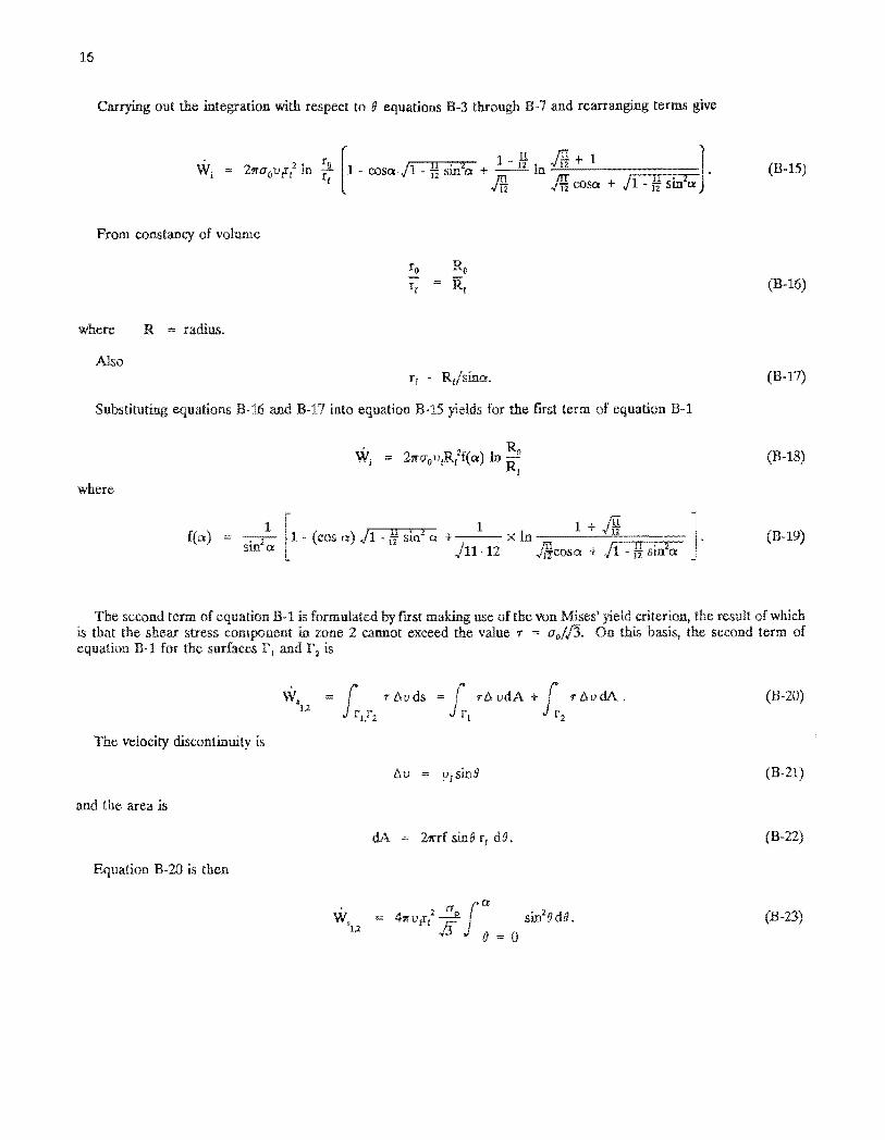
Carrying out the integration with respect to 9 equations B-3 through B-7 and rearranging terms give
W,i = 2Ttoav f i In ~1 e /n x 1
1 - cosaci - yf smza + In 4uJ%. Jti cosa + J l -H sinSa
(JB-15)
From constancy of volume
ro RoR, (B-16)
where R = radius.
Alsorf - Rj/sma,
Substituting equations B-16 and B-17 into equation B-15 yields for the first term of equation B-l
R 0
where
{(a) sin2 a
Wj = 2jrcr0i>,R(af(a) In —5
1 - (cos a) J l - $ sm"* a + 1 x In ■ 1 ^/11 12 j f i c o s a + Jl - ]4 sin2a ;
(B-17)
(B-18)
(B-19)
The sccond term of equation B-l is formulated by first making use of the von Mises5 yield criterion, the result of which is that the shear stress component in zone 2 cannot exceed the value r = o jfh . On this basis, the second term of equation B-l for the surfaces Fj and F2 is
W.1,2
/ r Auds = rA udA + I r AudA .ri,r2 J ri r2
The velocity discontinuity is
and the area is
Equation B-2G is then
At) = u(sin#
dA = 2«rf sin5 r, d&.
W5 = 4wvtTt4ura
siJ 0 = 0
sm28d9.
(B-20)
(B-21)
(B-22)
(B-23)
17
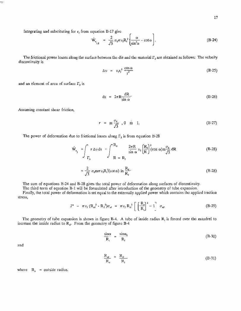
Integrating and substituting for r( from equation B-17 give2
W.u 73 sin2aco ta (B-24)
The frictional power losses along the surface between the die and the material F3 are obtained as follows: The velocity discontinuity is
, cosa Au = v,r, — 2— (B-25)
and an element of area of surface T, is
ds = 2ttR—dR
sin a (B-26)
Assuming constant shear friction,
r = m , 0 m 1.73
(B-27)
The power of deformation due to frictional losses along T3 is from equation B-28
Wc = t Au ds =•R„
R = R,
2 ttRsin a
! V 2R (cos a)m-£_ dR
73(B-28)
2 R a= — a0m7TufR f2(co ta ) In ——'
73 Rf(B-28)
The sum of equations B-24 and B-28 gives the total power of deformation along surfaces of discontinuity.The third term of equation B-l will be formulated after introduction of the geometry of tube expansion.Finally, the total power of deformation is set equal to the externally applied power which contains the applied traction
stress,
J ' ttv, (Rof - R^ )asi = nvr Rtf r r .L v. R, L v. 1.
- 1 (B-29)
The geometry of tube expansion is shown in figure B-4. A tube of inside radius R; is forced over the mandrel to increase the inside radius to R .̂ From the geometry of figure B-4
srna sma0~R~ =
and
Rot = R¡fR„ R¡
(B-30)
(B-31)
where R0 = outside radius.

18
Z o n e 2
Figure B-4-Geometry of tube expansion.
A pplying equation B-18 to tube expansion gives for the in ternal power of deformation
W j = 2 n a 0v t Ror2 f(a0) l n j ^ - R , 2 f ( a ) l n ^ -K rtf K:fRif— (jnU» , jsin a
f(a 0)sin2a 0 f(a)sin2a ■"I"
A pplying equation B-24 to tube expansion yields the power along surfaces of velocity discontinuity and
w v = [ I * ] 1 [ ( s- ^ ; C 0 t o . ) - ( ! ] ' (¿ „ C O .C
Applying equation B-28 to the surface P3 gives frictional loss
W , = p a 0m n v { R a2 (cota) In ^ ‘ 3 73 Ri
Frictional losses along the length, L, of contact between mandrel and tube are included as
The third term of equation B-l applied to tube expansion is
W b = - f s T u j ds = 7tu0 (R 02 - Ri2) a A = n v { (R ot2 - R^2) a A = n v ^ . 2 | J|- 0j - 1
(B-32)
(B-33)
(B-34)
(B-35)
(B-36)

19
Sum m ing equations B-32 through B-34 gives the total pow er of deform ation J* and setting the result equal to equation B-29 gives
? R if2Z7T CJqU í , aSin ot
f (a 0) sm 2a 0 - f(a ) sin2a
+ m co ta Ln r ^ i + _ l I R, J R.r
+ 7T VfR / (ir)1- 1 TTVfRi/ ( l ) :- 1 (B-37)
R earrang ing gives
(2/J 3 )a 0 (2 /J 3 )o 0+ A (B-38)
where A ' ( r T r ? - 1 Y 3 F<7) ln ( 1 “) ' ( ¿ 5 ' ]
and
+ m c o ta In (B-39)
F(7) = —sm an— it • i 7z— n— :--- 1 . Ju cosa + A -1 sin2a I An\cosa 71 - -2 sm a - co sa0 J l - % sm a0 + --------- ln ^ \ (B-40)
V11 • 12 J\ \ co sa0 + J 1 - 12 sin2a 0 _
E quation B-38 estim ates the stress required to extrude the sm aller d iam eter tube over the m andrel. W here no o ther stress is applied to the work, is zero. T he force requ ired for extrusion is then
F = - tt(R 02 - R,2) ^ . (B-41)
E quation B-38 also contains d im ensional constants, angles, and friction factor. W hen a < a 0 < 65°, f(a ) = f (a 0)1 w ithin 5% and the constan t A can be approxim ated by
A = m, R¡t Lco ta ln ~ + ——R, R» (b42)
INT.BU.OF MINES,PGH.,PA 29015


![[Free Scores.com] Strauss Johann the Beautiful Blue Danube 9279](https://static.fdocuments.us/doc/165x107/55cf8ecb550346703b95b32e/free-scorescom-strauss-johann-the-beautiful-blue-danube-9279.jpg)