Tube-Mac Flaring Machine Information Package TFM 01, TFM … · Tube-Mac Flaring Machine...
15
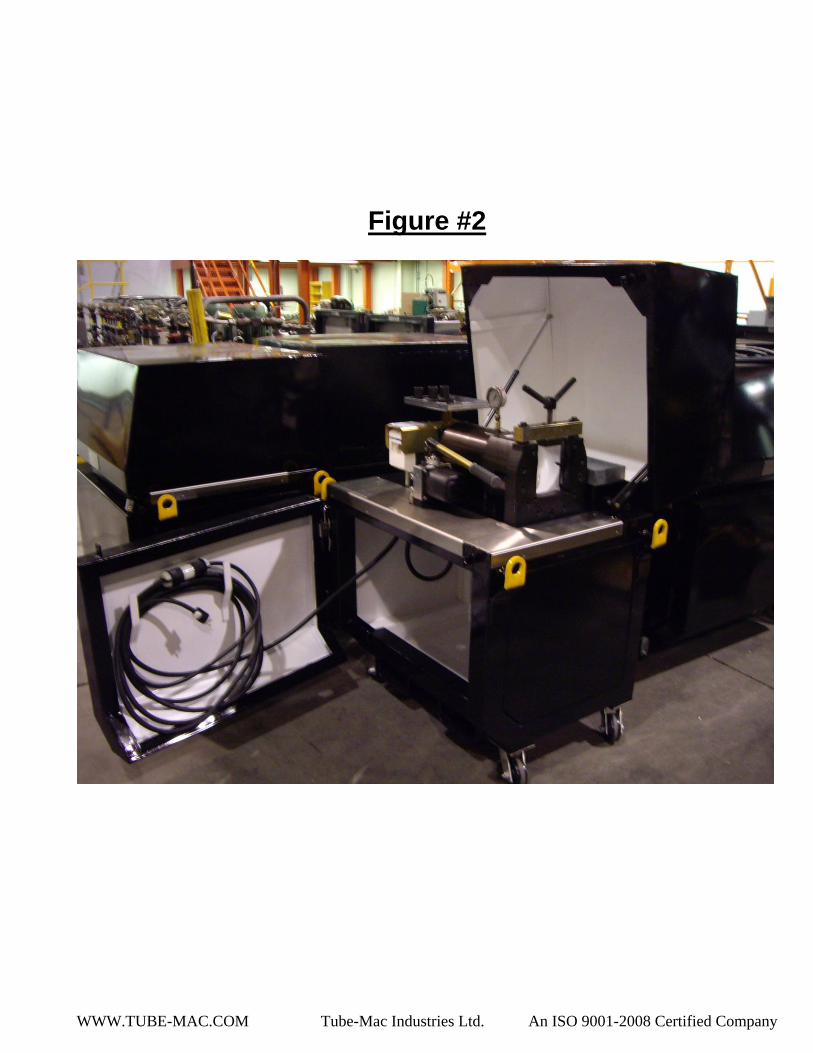
Tube-Mac Flaring Machine Information Package TFM – 01, TFM-01-LS The purpose of the TUBE-MAC® Industries TFM-01 and TFM-01-LS flaring machine is to produce a 37° flared pipe end in either cold drawn carbon steel or stainless steel pipe/tube. The TFM 01 flaring machine will produce a quality surface finish to meet the TUBE-MAC® flare flange/cone insert. The TFM-01 is the standard design which has the greatest range of sizes for NPS, Metric and OD Tube. The new designed TFM-01-LS has been developed for heavier walled Pipe and Tube and is suggested for sizes such as 2” Sch.160 and 4” Sch.80 Pipe or 60x8mm and 115x7mm metric tube. Capacity: TFM-01 or TFM-01-220 ` NPS from ½” thru 3” Sch. 80, 3-1/2” and 4” Sch. 40 Metric from 12mm thru 115mm x 7mm wall O.D. Tubes from ½” thru to 2” TFM-01-LS or TFM-01-LS-220 (Low Speed) NPS from 1” Sch. 80 thru to 4” Sch.80 Metric from 38mmx 5mm thru to 115mmx 7mm Voltage: TFM-01 120/1Ø/60hz TFM-01-220 220/1Ø/50hz Weight: 920 lbs./ 417 kg Standard Construction (See Figures #1, 2 and 3 below): Hard rubber rotating Castors located at each bottom corner and a maximum width of 30” (760mm) allow for easy maneuvering of unit anywhere in a facility. (Fig.7) A 30ft (9m) power cord will reach any electrical outlet or generator (Fig.2)
Transcript of Tube-Mac Flaring Machine Information Package TFM 01, TFM … · Tube-Mac Flaring Machine...

Tube-Mac Flaring Machine Information Package
TFM – 01, TFM-01-LS The purpose of the TUBE-MAC® Industries TFM-01 and TFM-01-LS flaring machine is to produce a 37° flared pipe end in either cold drawn carbon steel or stainless steel pipe/tube. The TFM 01 flaring machine will produce a quality surface finish to meet the TUBE-MAC® flare flange/cone insert. The TFM-01 is the standard design which has the greatest range of sizes for NPS, Metric and OD Tube. The new designed TFM-01-LS has been developed for heavier walled Pipe and Tube and is suggested for sizes such as 2” Sch.160 and 4” Sch.80 Pipe or 60x8mm and 115x7mm metric tube.
Capacity: TFM-01 or TFM-01-220
` NPS from ½” thru 3” Sch. 80, 3-1/2” and 4” Sch. 40 Metric from 12mm thru 115mm x 7mm wall
O.D. Tubes from ½” thru to 2”
TFM-01-LS or TFM-01-LS-220(Low Speed) NPS from 1” Sch. 80 thru to 4” Sch.80 Metric from 38mmx 5mm thru to 115mmx 7mm
Voltage: TFM-01 120/1Ø/60hz
TFM-01-220 220/1Ø/50hz
Weight: 920 lbs./ 417 kg Standard Construction (See Figures #1, 2 and 3 below):
Hard rubber rotating Castors located at each bottom corner and a maximum width of 30” (760mm) allow for easy maneuvering of unit anywhere in a facility. (Fig.7)
A 30ft (9m) power cord will reach any electrical outlet or generator (Fig.2)
WWW.TUBE-MAC.COM Tube-Mac Industries Ltd. An ISO 9001-2008 Certified Company
Oil drain below flaring pin allows for oil to drain away from flaring area to a collection bottle located underneath in the storage area of the machine (Fig 3)
Each unit comes with a pad lock to which locks the lid and front door shut to prevent damage or theft of tooling when not in use (Fig 5)
Four (4) bright yellow lifting eyelets at each corner of the unit allow for easy lifting with a crane or forklift to any destination such as on board a ship or above/below ground working areas (Fig 6)
Bottom of unit allows for storage of material or tooling that can be kept clean and safe behind the locked front door (Fig 3)
Flaring Die and Pin shelf located beside operating switch allows for easy access and storage of flaring machine accessories. (Fig 1)
Lid is easy to open due to a gas cylinder that helps with opening Handle of pump rotates 180° to allow operator to use either left
or right hand while operating unit (Fig 1) One piece barrel and rigid framework makes for a durable and
long lasting machine designed for a large range of flaring tube/pipe sizes (Fig 1)
Training on the use of the TFM-01 machine is simply and easy when Tube-Mac qualified personnel train the operators on proper operating procedures and maintenance of the machine
Maintenance: The TFM 01 flaring machine needs very little maintenance, as long as the machine is kept dry and clean. All bearings are of a standard type. Hydraulic fluid (Dexron III) must be checked occasionally and topped up as required. It is advised the flaring head be kept in the forward position when the machine is not in use, with the front end of piston flush with the front of cylinder. This is to protect the hydraulic cylinder against rust and dust. When replacing the cone bearings they can be removed easily with the threaded “back plate” (Part# TL-0112) which is behind the cone bearings, using slide hammer. When replacing the bearings it is imperative to always replace both bearings and pack each with high pressure grease. Using the provided diagram (located on each machine), position the bearings and back plate in the proper arrangement in the shaft support area. See Figure “A” for bearing alignment and configuration when changing out damaged shaft support bearings.

WWW.TUBE-MAC.COM Tube-Mac Industries Ltd. An ISO 9001-2008 Certified Company
Figure “A”
Shaft Support (Cone) Bearings – Configuration for Bearing Change
←Back of Machine (Cylinder End) (See Fig.1) Front of Machine (Flaring End) →

WWW.TUBE-MAC.COM Tube-Mac Industries Ltd. An ISO 9001-2008 Certified Company
WWW.TUBE-MAC.COM Tube-Mac Industries Ltd. An ISO 9001-2008 Certified Company
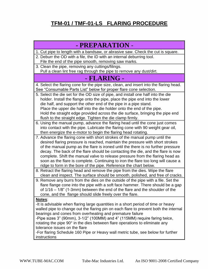
TFM-01 / TMF-01-LS FLARING PROCEDURE
- PREPARATION - 1. Cut pipe to length with a bandsaw, or abrasive saw. Check the cut is square.
2. Deburr the OD with a file, the ID with an internal deburring tool. File the end of the pipe smooth, removing saw marks.
3. Clean the pipe, removing any cuttings/filings. Pull a clean lint free rag through the pipe to remove any dust/dirt.
- FLARING - 4. Select the flaring cone for the pipe size, clean, and insert into the flaring head. See “Consumable Parts List” below for proper flare cone selection.
5. Select the die set for the OD size of pipe, and install one half into the die holder. Install the flange onto the pipe, place the pipe end into the lower die half, and support the other end of the pipe in a pipe stand. Place the upper die half into the die holder onto the end of the pipe. Hold the straight edge provided across the die surface, bringing the pipe end flush to the straight edge. Tighten the die clamp firmly.
6. Using the manual pump, advance the flaring head until the cone just comes into contact with the pipe. Lubricate the flaring cone with 90 weight gear oil, then energize the e-motor to begin the flaring head rotating.
7. Advance the flaring cone with short strokes of the manual pump until the desired flaring pressure is reached, maintain the pressure with short strokes of the manual pump as the flare is ironed until the there is no further pressure decay. The back of the flare should be contacting the die, and the flare is now complete. Shift the manual valve to release pressure from the flaring head as soon as the flare is complete. Continuing to iron the flare too long will cause a ridge to form in the bore of the pipe. Reference the chart below.
8. Retract the flaring head and remove the pipe from the dies. Wipe the flare clean and inspect. The surface should be smooth, polished, and free of cracks.
9. Remove any burrs from the dies on the outside of the pipe with a file. Set the flare flange cone into the pipe with a soft face hammer. There should be a gap of 1/16 – 1/8” (1-3mm) between the end of the flare and the shoulder of the cone, and the flange should slide freely over the flare.
Notes: -It is advisable when flaring large quantities in a short period of time or heavy walled pipe to change out the flaring pin on each flare to prevent both the internal bearings and cones from overheating and premature failure -Pipe sizes 3” (90mm), 3-1/2” (100MM) and 4” (115MM) require faring twice, rotating the pipe 90° in the dies between flare operations to eliminate any tolerance issues on the flare -For flaring Schedule 160 Pipe or Heavy wall metric tube, see below for further instructions

WWW.TUBE-MAC.COM Tube-Mac Industries Ltd. An ISO 9001-2008 Certified Company
Flaring Procedure for Schedule 160 Pipe (1 ½” thru 2 ½”) and
Heavy Wall Metric Tube (50mm thru 75mm) Use a good quality high temperature grease to pack the bearings. Repack the bearings every 6 flares. Will need at least a quantity of (4) TL-0012A flare pins (extra pins are required for rotating between each one to allow to cool)
1. Start with the pipe end .125” (3mm) - .150” (4mm) proud of the dies.
2. Clamp the pipe tightly in the dies. Mark the pipe at the back of the dies to see if there is any
slippage while flaring.
3. Advance the TL-0012A flare pin/head and begin the flare @ 60bar.
4. Continue to advance the flare pin as long as the pressure continues to decay, increasing
pressure in 10bar steps as pressure decay slows. Increase to maximum 110bar over
maximum 1½ minutes total flaring time.
5. Retract flare pin/head, change pin (to allow cooling) and rotate pipe 90° in dies.
6. Flare starting @ 100bar, increasing to 110bar for maximum ½ minute total flaring time.
7. Flare is now complete. File any burrs/ridges on the OD of the pipe from the dies.
8. Flange should slide over the flare, with minimal clearance between OD of flare and ID of
flange.
**Pressures and durations will vary with wall thickness and material strength**
*Pipe sizes 3” (90mm), 3-1/2” (100MM) and 4” (115MM) require faring twice, rotating the pipe
90° in the dies between flare operations to eliminate any tolerance issues on the flare*
FLARING PRESSURE and DURATION
PIPE SIZE Pressure** Duration**
1/2” 20MM 30 - 50 bar 3 - 6 seconds
3/4” 25MM 40 - 50 bar 5 -10 seconds
1” 30MM 40 - 60 bar 5 -10 seconds
1-1/4” 38MM 50 - 70 bar 5 -10 seconds
1-1/2” 50MM 60 - 80 bar 7 -20 seconds
2” 60MM 70 - 80 bar 8 -20 seconds
2-1/2” 75MM 70 - 100 bar 15 - 60 seconds
3” 90MM 80 - 110 bar 30 - 120 seconds*
3-1/2” 100MM 80 - 110 bar 30 - 120 seconds*
4” 115MM 80 - 110 bar 30 - 120 seconds*

WWW.TUBE-MAC.COM Tube-Mac Industries Ltd. An ISO 9001-2008 Certified Company
Consumable Parts List
Pipe Flaring Pins
Item # Part Number Description
1 TL-0011A 1/2” to 1” Pipe
12mm to 30mm
1/2”to 1” OD Tube
2 TL-0012A 1 ¼” to 1 ½” Pipe & 1 ½” thru 2 ½” Sch.160
38mm and 50mm and 60mm/75mm x 8mm<
1 ½”to 2” OD Tube
3 TL-0013A 2” to 2 ½” /
60mm and 75mm
4 TL-0014A 3”
90mm
5 TL-0017A 3 ½”
100mm
6 TL-0018A 4”
115mm
Metric Tube Flaring Dies
Item # Part Number Description
1 PFD-M12 12mm Pipe Die
2 PFD-M16 16mm Pipe Die
3 PFD-M20 20mm Pipe Die
4 PFD-M25 25mm Pipe Die
5 PFD-M30 30mm Pipe Die
6 PFD-M38 38mm Pipe Die
7 PFD-M42 42mm Pipe Die
8 PFD-M50 50mm Pipe Die
9 PFD-M60 60mm Pipe Die
10 PFD-M75 75mm Pipe Die
11 PFD-M90 90mm Pipe Die
12 PFD-M100 100mm Pipe Die
13 PFD-M115 115mm Pipe Die
WWW.TUBE-MAC.COM Tube-Mac Industries Ltd. An ISO 9001-2008 Certified Company
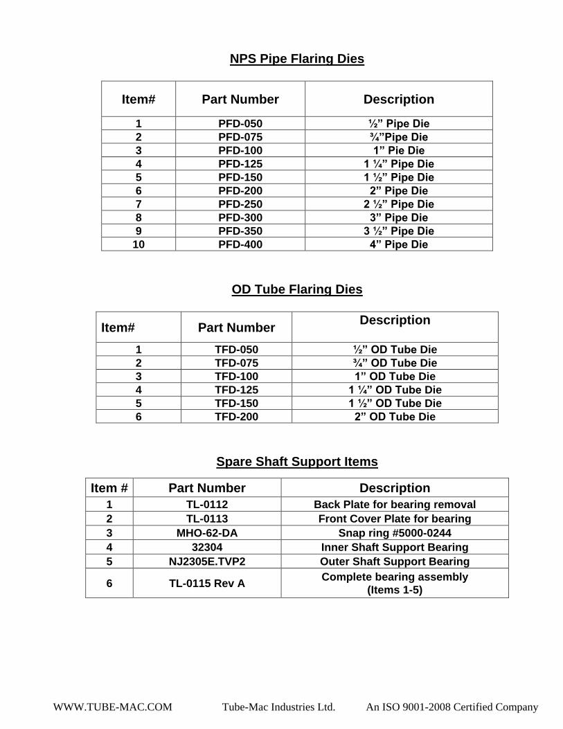
NPS Pipe Flaring Dies
Item# Part Number Description
1 PFD-050 ½” Pipe Die
2 PFD-075 ¾”Pipe Die
3 PFD-100 1” Pie Die
4 PFD-125 1 ¼” Pipe Die
5 PFD-150 1 ½” Pipe Die
6 PFD-200 2” Pipe Die
7 PFD-250 2 ½” Pipe Die
8 PFD-300 3” Pipe Die
9 PFD-350 3 ½” Pipe Die
10 PFD-400 4” Pipe Die
OD Tube Flaring Dies
Item# Part Number Description
1 TFD-050 ½” OD Tube Die
2 TFD-075 ¾” OD Tube Die
3 TFD-100 1” OD Tube Die
4 TFD-125 1 ¼” OD Tube Die
5 TFD-150 1 ½” OD Tube Die
6 TFD-200 2” OD Tube Die
Spare Shaft Support Items
Item # Part Number Description
1 TL-0112 Back Plate for bearing removal
2 TL-0113 Front Cover Plate for bearing
3 MHO-62-DA Snap ring #5000-0244
4 32304 Inner Shaft Support Bearing
5 NJ2305E.TVP2 Outer Shaft Support Bearing
6 TL-0115 Rev A Complete bearing assembly
(Items 1-5)

WWW.TUBE-MAC.COM Tube-Mac Industries Ltd. An ISO 9001-2008 Certified Company
Spare Consumable Flaring Items
Item # Part Number Description
1 Noga S-10 Replacement Reamer Blades
2 80w90 Gear Oil Gear Oil for Flaring Process
3 Extreme Pressure Grease Grease for Shaft Support Bearings
4 Dexron III Oil for Flaring Machine Reservoir
*For all other inquires for spare parts please consult factory or local
representative*

WWW.TUBE-MAC.COM Tube-Mac Industries Ltd. An ISO 9001-2008 Certified Company
Figure #1
←Back of machine (Cylinder End) Front of Machine (Flaring End)→
WWW.TUBE-MAC.COM Tube-Mac Industries Ltd. An ISO 9001-2008 Certified Company
Figure #2

WWW.TUBE-MAC.COM Tube-Mac Industries Ltd. An ISO 9001-2008 Certified Company
Figure #3

WWW.TUBE-MAC.COM Tube-Mac Industries Ltd. An ISO 9001-2008 Certified Company
Figure #4

WWW.TUBE-MAC.COM Tube-Mac Industries Ltd. An ISO 9001-2008 Certified Company
Figure#5

WWW.TUBE-MAC.COM Tube-Mac Industries Ltd. An ISO 9001-2008 Certified Company
Figure #6
Figure #7