TTx Aerial In-Line Terminal (SDP-T Aerial In-Line Terminal ... · SDP-T Aerial Inline Terminal for...
16
SDP-T Aerial Inline Terminal for FTTx JK Dynamic Co., Ltd. www.jk-dynamic.com Tel : 02-159-8014 Fax : 02-159-8041 Page 1 TTx Aerial In-Line Terminal (SDP-T Aerial In-Line Terminal for FTTx) Optical Fiber Inline Closure Spec. No. CB-SDP-045-01 Model FOC-CB8-16. Available with optical fiber cable enclosure for fiber splice, splitter in outside plant network for FTTx and broadband applications., water protection proof, Designed for quick installation and easy to use, Thus saving time in the workplace. The closure has 6 cable entry ports. The entries can be 1 : 2, 1 : 4, 1 : 8 and 1 : 16 Splitter. Features - Made from Material Acrylonitrile Butadiene Styrene (ABS), Resistant sunlight (UV) and climatic conditions of the acid and alkali, vibration resistant, Durable pull and bend of cable it well. - Easy to install (Clip Lock) - Can be open and close lid easily without special tools. - Design a clamp attached on the lid, for easy to use, dropped during operation. - Prepare successful accessories, easily installed and reduce the time of installation. - Can be install cable freely and easily with a clamp lock optical fiber cable in order to keep tidy. - Provide hanging clamp Stainless SUB 304 and disconnect from cable stand, convenient fast install and can be use aerial and air-mounted on pole. - Designed front cover with space for company name or sprayed or painted stripes Logo is permanently attached to the plastic. - Splice Tray and lid made from Polycarbonate or white ABS. - Protective Sleeve length 60 mm and core made of Stainless Steel. - Size: 32.05 x 18 x 12 cm - Weight 2 kg with 6 holes for cable in-out. - IP 65 , 68 Brand : Chamber, Products made in Thailand F
Transcript of TTx Aerial In-Line Terminal (SDP-T Aerial In-Line Terminal ... · SDP-T Aerial Inline Terminal for...
SDP-T Aerial Inline Terminal for FTTx
JK Dynamic Co., Ltd. www.jk-dynamic.com Tel : 02-159-8014 Fax : 02-159-8041 Page 1
TTx Aerial In-Line Terminal
(SDP-T Aerial In-Line Terminal for FTTx)
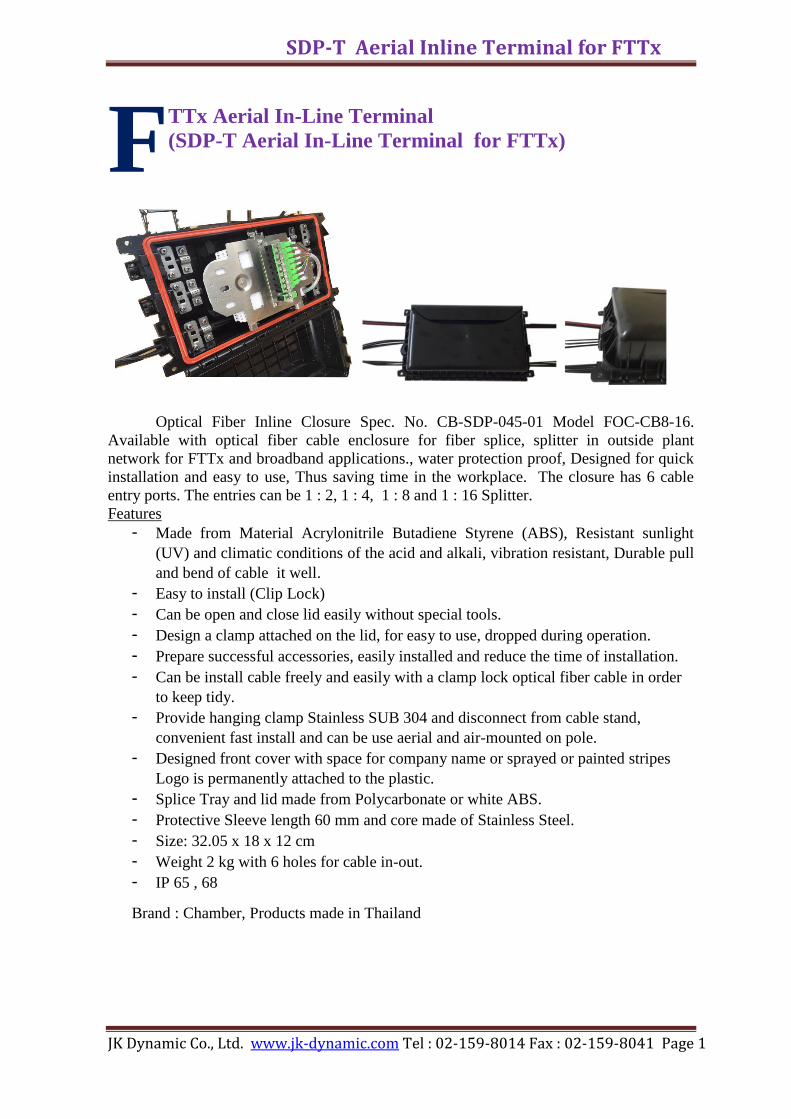
Optical Fiber Inline Closure Spec. No. CB-SDP-045-01 Model FOC-CB8-16.
Available with optical fiber cable enclosure for fiber splice, splitter in outside plant
network for FTTx and broadband applications., water protection proof, Designed for quick
installation and easy to use, Thus saving time in the workplace. The closure has 6 cable
entry ports. The entries can be 1 : 2, 1 : 4, 1 : 8 and 1 : 16 Splitter.
Features
- Made from Material Acrylonitrile Butadiene Styrene (ABS), Resistant sunlight
(UV) and climatic conditions of the acid and alkali, vibration resistant, Durable pull
and bend of cable it well.
- Easy to install (Clip Lock)
- Can be open and close lid easily without special tools.
- Design a clamp attached on the lid, for easy to use, dropped during operation.
- Prepare successful accessories, easily installed and reduce the time of installation.
- Can be install cable freely and easily with a clamp lock optical fiber cable in order
to keep tidy.
- Provide hanging clamp Stainless SUB 304 and disconnect from cable stand,
convenient fast install and can be use aerial and air-mounted on pole.
- Designed front cover with space for company name or sprayed or painted stripes
Logo is permanently attached to the plastic.
- Splice Tray and lid made from Polycarbonate or white ABS.
- Protective Sleeve length 60 mm and core made of Stainless Steel.
- Size: 32.05 x 18 x 12 cm
- Weight 2 kg with 6 holes for cable in-out.
- IP 65 , 68
Brand : Chamber, Products made in Thailand
F
SDP-T Aerial Inline Terminal for FTTx
JK Dynamic Co., Ltd. www.jk-dynamic.com Tel : 02-159-8014 Fax : 02-159-8041 Page 2
1. GENERAL 1.1 This specification covers requirement of the aerial., In-Line , re-enterable, fiber
optic terminal for drop termination that shall be met to ensure the satisfactory
operation of a fiber optic terminal in outside plant environments.
1.2 The FTTx aerial in-line terminal herein after referred to as the “terminal” shall
be applied to use for covering the spliced fibers of optical fiber and the termination
of optical fiber drop cable in access network installing in aerial optical fiber cable
network of TOT public company Limited. The terminal according to this
specification shall be categorized to one types as follows :-
- The terminal for the optical splitter distribution point (SDP-T)
1.3 Full details of this following information shall be provided in the document.
- Product specification issued by product manufacturer.
- The material and grade of material used as per Section 3.1 in this
specification.
- Test method and test report issued by manufacturer or third party laboratory
or TOT to certify the product offered meeting the requirements as specified
herein or meeting international standard.
2. General Requirements
2.1 The configuration of the terminal shall be in-Line design which shall
accommodate self supporting cable passing intact through the terminal or shall
accommodate cable passing through the terminal which is supported by a separated
messenger (or stand) wire. The terminal shall be allowable for easy re-entry,
splicing, assembly and installation..
2.2 The design of the terminal body housing required for this specification shall be
of clam shell configuration with the parting line on the vertical axis and a freely
operating hinge along the horizontal bottom edge. The two halves of the terminal
body are to be closed and sealed with a suitable arrangement of over centre latch,
quick snap, snap lock or clip type fasteners or equivalent. Once the terminal is
installed the rear half of the terminal body shall, at all times, remain firmly attached
to the main cable. Releasing the front half of the terminal body and allowing it to
rotate downwards in order to provide the faster installation time and to facilitate
working on the ladder while doing maintenance or drop wire installation without
bring the terminal down to work on the ground.
2.3 The terminal shall be easy for handling and installation. The terminal shall
allow easy fiber access during installation and maintenance. The terminal, when re-
entry (it means to open and close the terminal body), shall require neither sealing
materials nor re-entry kit.
2.4 The terminal shall be possible to terminate different cable types.
a) Main cable Single mode optical fiber cable Spec. No. OES-004-030-xx,
ADSS OFC Spec.No. OES-004-045-xx, OFC for access services (drop wire
twisted). Spec. No. OES-004-044-xx, and Armoured OFC for access service
(Armoured drop wire twisted) Spec. No. OES-004-052-xx,xx=latest issue.
SDP-T Aerial Inline Terminal for FTTx
JK Dynamic Co., Ltd. www.jk-dynamic.com Tel : 02-159-8014 Fax : 02-159-8041 Page 3
b) Drop cable Optical fiber drop cable or called “Optic drop wire for FTTx”
(round type, sizing diameter up to 3.5 mm) Spec.No. OES-004-049-xx, xx=latest
issue.
2.5 The strength members of the main cables shall be mechanically attached to the
inner hardware of the terminal..
2.6 The terminal shall provide the suitable lock system for each drop cable before
going out from the terminal in order to prevent the tension affecting to drop
termination in patching area.
2.7 The terminal shall be able of accepting additional main and branch cable
without removal of the sheath retention or strength member clamping hardware on
previously terminated cables or disturbing existing splices. The terminal shall be
able to accommodate at least one branch cable up to 24 fibers
2.8 The terminal shall be sealed with high effective method to assure that the
closure shall be able to comply with the requirement as specified in this
specification.
2.10 All small parts of fastener hardware used to assemble the closure body for
opening/closing the closure by Clip Lock for easy workability during installation
and maintenance activities.
2.11 The internal threads (if molded in non metallic material) of closure housing
(only part for opening/closing the closure), strength member clamps and cable
clamps shall be made from stainless steel grade SUB 304.
2.12 The terminal shall provide storage area for uncut (or looped-through) buffer
tubes in a minimum length of 1.2 meters (referred to maximum cable diameter of
each terminal capacity as specified in Table 1). The storage space shall be designed
to be easy for workability during installation and maintenance activities. The
terminal shall provide unobstructed access to gather the uncut buffer tubes in the
storage space.
2.13 The outside of the terminal (backside) shall provide the drop cable loop
holder for storing the drop cable according to section 2.4 b) (1F, round type with
messenger wire) before entering to drop port of the closure in a minimum length of
46 meters (5.7 m per 1 drop port).
2.14 Each terminal type shall be divided into two sections: a main or distribution
splice section and a drop termination section. The drop termination section shall be
called the patching area. The splitter may be installed in the distribution splice
section or in the drop termination section. The drop termination section may be
installed in the organizer tray depending on manufacturer design.
2.15 The terminal shall at least contain the cable entrance ports as specified in
Table 1, Each cable ports required as per table 1 shall be capable to accommodate
the cable up to the closure capacity and according to application in Section 1.2
and 2.4. Unused cable ports shall be closed with plugs or equivalent.
2.16 The terminal shall be capable of accommodating the organizer tray (the
splitter tray and the splice trays) which accept fusion splice method or mechanical
splice method. The terminal shall have provisions, for storing fiber splices in an
orderly and identifiable manner,,mountings fiber splice in an orderly and
identifiable manner, mounting for splice organizer assembly and space for fiber
SDP-T Aerial Inline Terminal for FTTx
JK Dynamic Co., Ltd. www.jk-dynamic.com Tel : 02-159-8014 Fax : 02-159-8041 Page 4
access. The splice protector sleeve holder and the splitter holder which fixed on the
organizer tray shall be changeable and removable.
a) The splitter tray shall accommodate the splitter 1:2, 1:4 and 1:8 ratio and
shall have the features and compose of as follows:
- The splitter holder, to be installed on the splitter tray, shall be designed to
firmly, hold the splitter which made from various different manufacturers and
different splitter dimensions of 1:2, 1:4 and 1:8 splitter.
- One splitter holder (at least) shall be installed on the splitter tray and the
another splitter holder shall be installed in the same splitter tray or in the other
organizer tray for some application such as changing one splitter of 1:8 to two
splitters of 1:4 in order to up speed the FTTx service bandwidth etc. - The
splice protective sleeve holder (at least 3 fiber splices).
- The slot or other device to support for installation of SC/APC through
adaptor (at least for 1 adaptor) This slot or other device may be installed in the drop
termination section such as in the through adaptor panel.
In case of put the slot for SC/APC through adaptor in the splitter tray, the
slot (at least for 1 adaptor) shall be changeable and removable to interchange or
intermixing applications within the same terminal.
b) The splitter trays and the splice tray may be designed to build in the
same tray structure but on the different side (so called the combined back to back
splice and splitter tray). The other design may be the separated splice and splitter
tray depending on the manufacturer creation. However both designs shall not affect
to the terminal performance.
c) In case of the combined back to back splice and splitter tray or in case of
the separated splice and splitter tray, it shall be designed to allow either horizontal
(~140°-180°) splicing working position to facilitate the installer or maintenance
person to work on the ladder and on the ground respectively.
2.17 All fiber cable elements shall be routed in such a way that no transmission
degradation is seen after accessing these cable elements. The minimum bend radius
of the fibers after installation shall be 30 mm throughout the whole terminal system.
2.18 Installation of the closure shall not require special tool or equipment, other
than those normally carried by splicer or craftsman. The terminal shall be designed
for installation by using the amount of the terminal by clip lock., tool types as less
as possible. Tool-less installation and wrench tool of hex flat head bolt/nut (no. 10,
10 mm width) are preferably, the insert lock head bolt/nut shall not be allowable.
2.19 The terminal shall provide two self supporting aerial strand clamps which
made from stainless steel grade SUB 304. Its clamps shall be ready-installed
design.
2.20 The terminal shall have no sharp edges, corners, burrs or other hazardous
features that could result in damage to the fiber or injury to splicer or craftsman.
2.21 The terminal shall provide a robust mechanism for clamping the cable sheath
such as teeth clamp, adjustable clamp etc to prevent the cable sheath slipping or
pullout and terminal swing caused by surrounding environments for instance :-
strong wind in aerial network or cable slide in under-road network etc. Cable tie
SDP-T Aerial Inline Terminal for FTTx
JK Dynamic Co., Ltd. www.jk-dynamic.com Tel : 02-159-8014 Fax : 02-159-8041 Page 5
(made from non metallic material) shall not be allowable for wrapping, tightening
the main branch cable sheath to cable port.
2.22 The through adaptor shall be as follows :
Metallic part : made from Ni (nickel) plated brass or stainless steel grade
SUB 304 series
Sleeve : Ceramic alignment sleeve.
2.23 The splitter used for this specification shall be type A2 Splitter conforming to
TOT specification OES-001-076-xx Fiber optic splitter (xx=latest issue) or
equivalent type with connectorized both (input/output) sides of splitter. The splitter
shall be separately purchased. The terminal shall be designed to support to install
this splitter with completely assembling including wiring, routing, patching of
splitter accessories without affective the terminal performance
2.24 The bidder can propose the different design of the terminal or the splitter
from as specified in this specification which having better performance and easier-
operation than requirements in this specification. TOT bidding evaluation
committee or the person entrusted will considerate the design concept proposed and
make a decision.
2.25 The terminal kit shall at least consist of the following components:
a) Re-enterable, vertically split of the following components: 1 set.
b) The organizer tray : 1 set (compose of 1 splitter tray and 1 splice tray)
The splitter tray shall compose of:
● 1 splitter tray
● 2 splitter holders for 1: n splitter (n=number of splitting
Such as 1:2, 1:4, and 1:8 )
● 1 slot for installation the SC/APC Through adaptor 1 set
(for tray patching) only for the case of this slot is not install in
drop termination section.
The splice trays shall compose of:
● The terminal shall have at least 1 trays
(shall accommodate at least 24 fibers single fusion splices).
The splitter tray and the splice tray may be designed in separated tray
or designed to build in the same tray structure but on the different side (so called
combined back to back splice and slitter tray).
c) SC/APC through adaptor : 9 sets or up to order.
d) SC/APC through adaptor panel or slot: 1 set (support to install up to
12 SC/APC adaptors
e) Main cable port (or main port): as specified in table 1
f) Branch cable port (or branch port): as specified in table 1.
SDP-T Aerial Inline Terminal for FTTx
JK Dynamic Co., Ltd. www.jk-dynamic.com Tel : 02-159-8014 Fax : 02-159-8041 Page 6
g) Drop cable port (or drop port) : as specified in table 1
h) Clamping for mounting on cable strand 1 set
i) Heat shrink splice protector (Sleeve size 40mm) with stainless steel
reinforced metal rod (up to No. of splices)
j) Sealing gasket or sealing system (if any)
k) Sealing tape or equivalent
l) Buffer tube o transportation tube, if necessary depending on each
manufacturer product design.
m) Cable clamps
n) Tray strap
o) Alcohol tissue
p) Abrasive paper
q) Instruction at least one per terminal kit preparing in Thai
or English language including.
- Installation and maintenance instruction
- Description how to manage or arrange the fiber inside terminal
- Drawings or pictures of fully fiber installed inside closure and
Finish installed closure related to applications concerned.
3. Technical Requirements The change in attenuation (ΔAttn.) shall be performed in accordance with IEC
61300-3-5. An optical wavelength of 1550 nm ± 20 nm should be used to measure
performing on a minimum of 10 individual fibers. And if there is no specified in
some testing procedure, the test method should be done in practical way based on
TOT application. The terminal sample shall be fully assembled during the test in
Section 3.2 and 3.3.
3.1 Material Requirements
3.1.1 Housing or Covers shall be fabricated from black durable high density
thermoplastic, which resists to solvents and stress cracking and be compatible with
chemicals and other materials used in the various closure applications. This plastic
also resists deterioration when exposed to the ultraviolet ray of the sun for long life.
3.1.2 All gaskets shall be fabricated from high quality grade rubber or
equivalent and be compatible with chemicals and other materials to which they
might be exposed in normal applications.

SDP-T Aerial Inline Terminal for FTTx
JK Dynamic Co., Ltd. www.jk-dynamic.com Tel : 02-159-8014 Fax : 02-159-8041 Page 7
3.1.3 The organizer tray shall be made of polycarbonate or ABS or equivalent
and shall be designed for easy installation such as swing, drawer or hinging tray etc.
a) The splice tray the splitter tray and the other tray shall be white,
ivory, light grey color or equivalent.
b) The splice trays and splitter tray shall be clearly identified by
suitable method or the splitter tray shall have different color from the other tray
type.
3.1.4 Reinforced metal rod for protective sleeve shall be made of stainless
steel 300 series grade.
3.1.5 All metallic material parts of the terminal shall be made from ABS and
of corrosion resistance material which such metallic parts concern the cable
termination hardware, bonding and grounding hardware both, nut, washer and
screw etc. All parts of metallic materials shall be resistance and protected against
general corrosion and various forms of localized corrosion (e.g. stress corrosion,
cracking, pitting, etc.) and shall not be capable of inducing significant galvanic
corrosion effects when in contact with other metals likely to be present in the
closure’s environment.
a) Inside terminal Corrosion resistance material such as stainless steel
grade SUB 304.
If the galvanized steel or other steel materials that have corrosion
resistance property lower than stainless steel grade SUB 304 used, it shall be passed
the following requirement.
- No signs of corrosion shall be visible after 7 days exposure to
Non-acidic salt fog spray (5% NaCL, 35°C) according to
IEC 61300-2-26.
b) Outside terminal: High corrosion resistance material such as
stainless steel grade SUB 304. The properties of corrosion resistance
material lower than stainless steel grade SUB 304 are not allowable except
Section 2.10.

SDP-T Aerial Inline Terminal for FTTx
JK Dynamic Co., Ltd. www.jk-dynamic.com Tel : 02-159-8014 Fax : 02-159-8041 Page 8
3.2 Mechanical Requirements
Performance Conditions Requirements Method of
Test
in Section
3.2.1 Appearance ● Examination with the ● No defects which will 4.1.1
unaided naked eye adversely affect
product performance
3.2.2 Bending ● Temperature (40±2)°C ΔAttn. ≤ 0.05 dB
(flexure) ● Weight: up to cable ● Appearance 4.1.2
capacity
● No. of cycles: 8 cycles
3.2.3 Cable ● Temperature (25±2)°C ΔAttn. ≤ 0.05 dB 4.1.3
retention ● Weight: 45 kg. ● Appearance
● Time 1 half hour
3.2.4 Drop Cable ● Temperature (25±2)°C ΔAttn. ≤ 0.05 dB 4.1.4
retention ● Weight: 2.5 kg. ● Appearance
● Time 5 minutes
3.2.5 Torsion ● Temperature (40±2)°C ΔAttn. ≤ 0.05 dB 4.1.5
● No. of cycles: 10 cycles ● Appearance
3.2.6 Compression ● Temperature (40±2)°C ● Deform ≤ 20% while the
● Weight: up to cable load is applied and
capacity deformed ≤ 10% while remove 4.1.6
● Surface area: 50x50 mm²
the load.
● Time 15 minutes
3.2.7 Impact ● Temperature (40±2)°C ● Appearance
● Impact tool Ø 50 mm
4.1.7
hemisphere head cyUnder
● Weight: 2 kg
3.28 Vibration ● Temperature (25±2)°C ● Appearance
● Speed: 1 oct/min
4.1.8
● Frequency: 5 Hz~20 Hz
3.2.9 Through ● IEC-61300-2-2 ● Appearance
Adaptor ● Mating and Remating: ΔAttn. ≤ 0.2 dB -
Endurance 500 times ΔRL ≤ 2 dB
SDP-T Aerial Inline Terminal for FTTx
JK Dynamic Co., Ltd. www.jk-dynamic.com Tel : 02-159-8014 Fax : 02-159-8041 Page 9
3.3 Environmental Requirements
Performance Conditions Requirements Method of Test
in Section
3.3.1 Protection ● IEC 60529 or equivalent ● Dust-protected
Rating ● No evidence of water 4.2.1
(dust/water) intrusion
● IP 65 or equivalent
3.3.2 Ultraviolet ● ASTM D - 2526 ● Change in ultimate
Resistance ● Time : 30 days elongation and tensile 4.2.2
strength ≤ 20%
3.3.3 Carbon Black ● ASTM D - 1603 ● ≥ 2.6% 4.2.3
Content
3.3.4 Salt Fog ● ASTM B - 117 ● Appearance 4.2.4
Spray Test ● Time : 30 days ● No Corrosion
3.3.5 Temperature ● Temperature range: ● Appearance
Cycling 44°C/ +60°C
4.2.5
● Humidity: 95%
● Time: 30 days
4. Test Method 4.1 Mechanical Tests
4.1.1 Appearance
The terminal shall be inspected for flaws, defects, melts, pinholes,
cracks or inclusions visible to the naked eye. There shall be no
mechanical damage to the terminal, the cable sheath and terminal
clamping hardware.
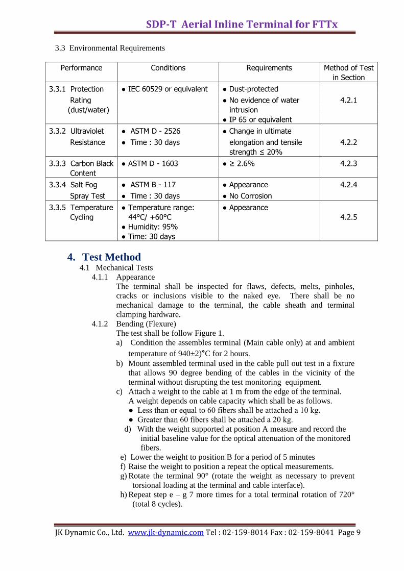
4.1.2 Bending (Flexure)
The test shall be follow Figure 1.
a) Condition the assembles terminal (Main cable only) at and ambient
temperature of 940±2)°C for 2 hours.
b) Mount assembled terminal used in the cable pull out test in a fixture
that allows 90 degree bending of the cables in the vicinity of the
terminal without disrupting the test monitoring equipment.
c) Attach a weight to the cable at 1 m from the edge of the terminal.
A weight depends on cable capacity which shall be as follows.
● Less than or equal to 60 fibers shall be attached a 10 kg.
● Greater than 60 fibers shall be attached a 20 kg.
d) With the weight supported at position A measure and record the
initial baseline value for the optical attenuation of the monitored
fibers.
e) Lower the weight to position B for a period of 5 minutes
f) Raise the weight to position a repeat the optical measurements.
g) Rotate the terminal 90° (rotate the weight as necessary to prevent
torsional loading at the terminal and cable interface).
h) Repeat step e – g 7 more times for a total terminal rotation of 720°
(total 8 cycles).
SDP-T Aerial Inline Terminal for FTTx
JK Dynamic Co., Ltd. www.jk-dynamic.com Tel : 02-159-8014 Fax : 02-159-8041 Page 10
After completion, there is no change in fiber attenuation greater
than 0.05 dB and the sample shall be subjected to appearance test as
per Section 4.1.1.
Fig. 1 Bending (Flexure)
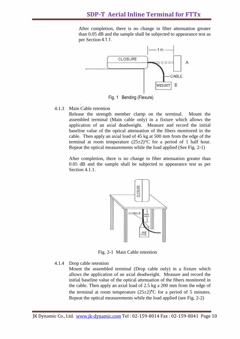
. 4.1.3 Main Cable retention
Release the strength member clamp on the terminal. Mount the
assembled terminal (Main cable only) in a fixture which allows the
application of an axial deadweight. Measure and record the initial
baseline value of the optical attenuation of the fibers monitored in the
cable. Then apply an axial load of 45 kg at 500 mm from the edge of the
terminal at room temperature (25±2)°C for a period of 1 half hour.
Repeat the optical measurements while the load applied (See Fig. 2-1)
After completion, there is no change in fiber attenuation greater than
0.05 dB and the sample shall be subjected to appearance test as per
Section 4.1.1.
Fig. 2-1 Main Cable retention
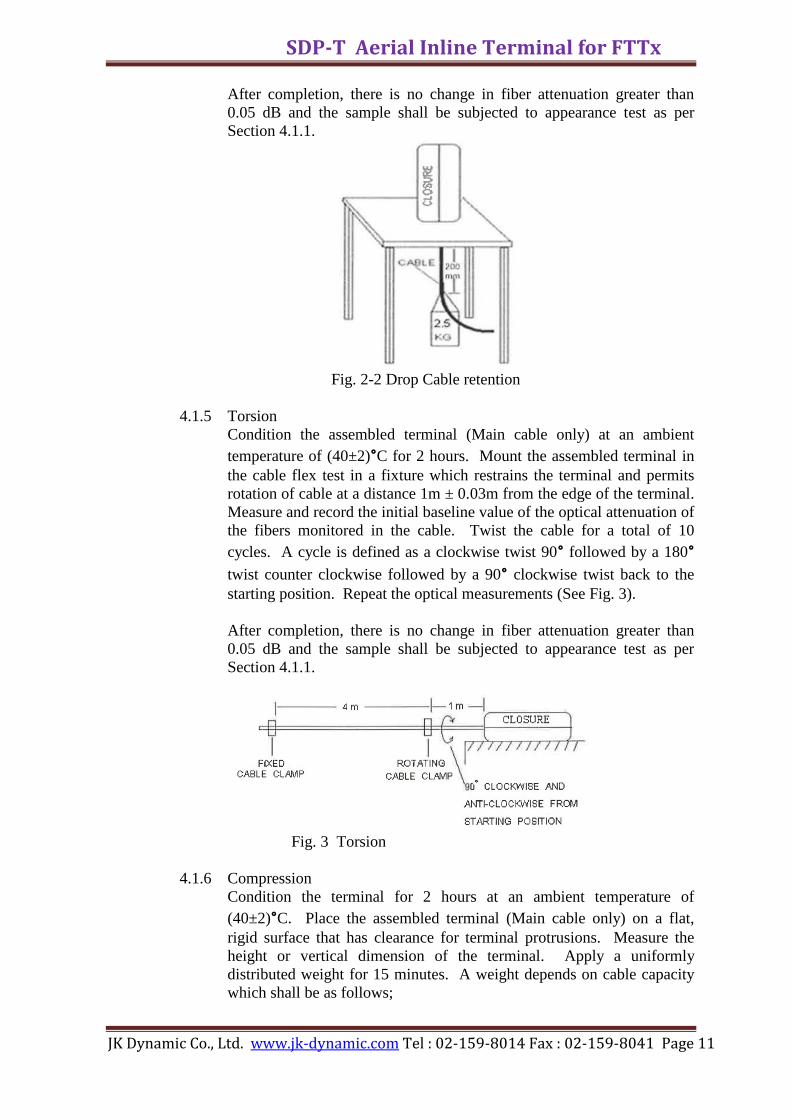
4.1.4 Drop cable retention
Mount the assembled terminal (Drop cable only) in a fixture which
allows the application of an axial deadweight. Measure and record the
initial baseline value of the optical attenuation of the fibers monitored in
the cable. Then apply an axial load of 2.5 kg a 200 mm from the edge of
the terminal at room temperature (25±2)°C for a period of 5 minutes.
Repeat the optical measurements while the load applied (see Fig. 2-2)
SDP-T Aerial Inline Terminal for FTTx
JK Dynamic Co., Ltd. www.jk-dynamic.com Tel : 02-159-8014 Fax : 02-159-8041 Page 11
After completion, there is no change in fiber attenuation greater than
0.05 dB and the sample shall be subjected to appearance test as per
Section 4.1.1.
Fig. 2-2 Drop Cable retention
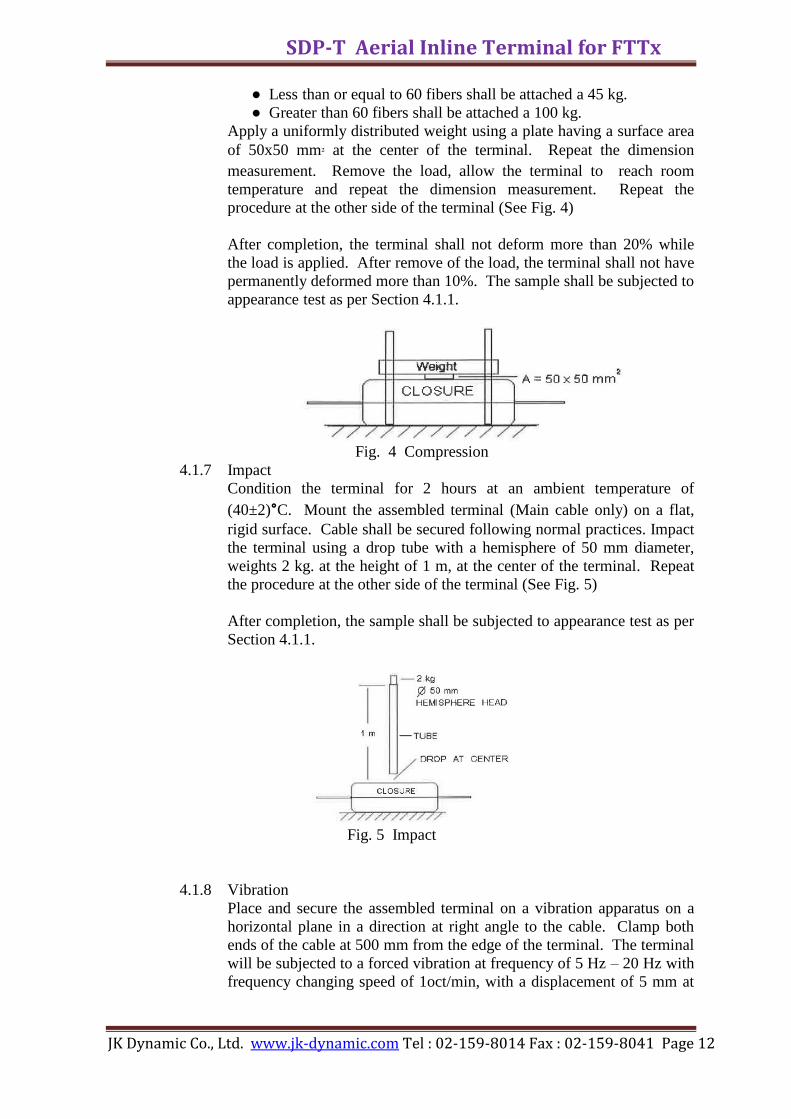
4.1.5 Torsion
Condition the assembled terminal (Main cable only) at an ambient
temperature of (40±2)°C for 2 hours. Mount the assembled terminal in
the cable flex test in a fixture which restrains the terminal and permits
rotation of cable at a distance 1m ± 0.03m from the edge of the terminal.
Measure and record the initial baseline value of the optical attenuation of
the fibers monitored in the cable. Twist the cable for a total of 10
cycles. A cycle is defined as a clockwise twist 90° followed by a 180°
twist counter clockwise followed by a 90° clockwise twist back to the
starting position. Repeat the optical measurements (See Fig. 3).
After completion, there is no change in fiber attenuation greater than
0.05 dB and the sample shall be subjected to appearance test as per
Section 4.1.1.
Fig. 3 Torsion
4.1.6 Compression
Condition the terminal for 2 hours at an ambient temperature of
(40±2)°C. Place the assembled terminal (Main cable only) on a flat,
rigid surface that has clearance for terminal protrusions. Measure the
height or vertical dimension of the terminal. Apply a uniformly
distributed weight for 15 minutes. A weight depends on cable capacity
which shall be as follows;
SDP-T Aerial Inline Terminal for FTTx
JK Dynamic Co., Ltd. www.jk-dynamic.com Tel : 02-159-8014 Fax : 02-159-8041 Page 12
● Less than or equal to 60 fibers shall be attached a 45 kg.
● Greater than 60 fibers shall be attached a 100 kg.
Apply a uniformly distributed weight using a plate having a surface area
of 50x50 mm² at the center of the terminal. Repeat the dimension
measurement. Remove the load, allow the terminal to reach room
temperature and repeat the dimension measurement. Repeat the
procedure at the other side of the terminal (See Fig. 4)
After completion, the terminal shall not deform more than 20% while
the load is applied. After remove of the load, the terminal shall not have
permanently deformed more than 10%. The sample shall be subjected to
appearance test as per Section 4.1.1.
Fig. 4 Compression
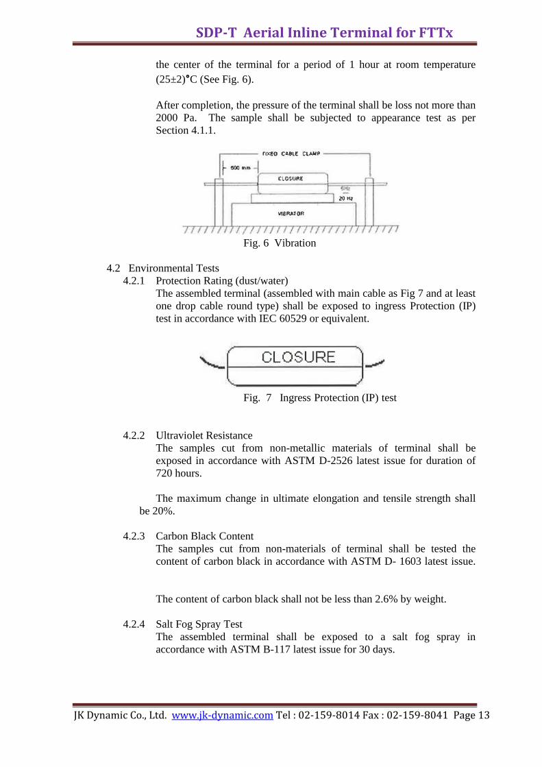
4.1.7 Impact
Condition the terminal for 2 hours at an ambient temperature of
(40±2)°C. Mount the assembled terminal (Main cable only) on a flat,
rigid surface. Cable shall be secured following normal practices. Impact
the terminal using a drop tube with a hemisphere of 50 mm diameter,
weights 2 kg. at the height of 1 m, at the center of the terminal. Repeat
the procedure at the other side of the terminal (See Fig. 5)
After completion, the sample shall be subjected to appearance test as per
Section 4.1.1.
Fig. 5 Impact
4.1.8 Vibration
Place and secure the assembled terminal on a vibration apparatus on a
horizontal plane in a direction at right angle to the cable. Clamp both
ends of the cable at 500 mm from the edge of the terminal. The terminal
will be subjected to a forced vibration at frequency of 5 Hz – 20 Hz with
frequency changing speed of 1oct/min, with a displacement of 5 mm at
SDP-T Aerial Inline Terminal for FTTx
JK Dynamic Co., Ltd. www.jk-dynamic.com Tel : 02-159-8014 Fax : 02-159-8041 Page 13
the center of the terminal for a period of 1 hour at room temperature
(25±2)°C (See Fig. 6).
After completion, the pressure of the terminal shall be loss not more than
2000 Pa. The sample shall be subjected to appearance test as per
Section 4.1.1.
Fig. 6 Vibration
4.2 Environmental Tests
4.2.1 Protection Rating (dust/water)
The assembled terminal (assembled with main cable as Fig 7 and at least
one drop cable round type) shall be exposed to ingress Protection (IP)
test in accordance with IEC 60529 or equivalent.
Fig. 7 Ingress Protection (IP) test
4.2.2 Ultraviolet Resistance
The samples cut from non-metallic materials of terminal shall be
exposed in accordance with ASTM D-2526 latest issue for duration of
720 hours.
The maximum change in ultimate elongation and tensile strength shall
be 20%.
4.2.3 Carbon Black Content
The samples cut from non-materials of terminal shall be tested the
content of carbon black in accordance with ASTM D- 1603 latest issue.
The content of carbon black shall not be less than 2.6% by weight.
4.2.4 Salt Fog Spray Test
The assembled terminal shall be exposed to a salt fog spray in
accordance with ASTM B-117 latest issue for 30 days.
SDP-T Aerial Inline Terminal for FTTx
JK Dynamic Co., Ltd. www.jk-dynamic.com Tel : 02-159-8014 Fax : 02-159-8041 Page 14
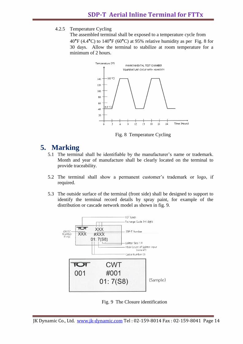
4.2.5 Temperature Cycling
The assembled terminal shall be exposed to a temperature cycle from
40°F (4.4°C) to 140°F (60°C) at 95% relative humidity as per Fig. 8 for
30 days. Allow the terminal to stabilize at room temperature for a
minimum of 2 hours.
Fig. 8 Temperature Cycling
5. Marking 5.1 The terminal shall be identifiable by the manufacturer’s name or trademark.
Month and year of manufacture shall be clearly located on the terminal to
provide traceability.
5.2 The terminal shall show a permanent customer’s trademark or logo, if
required.
5.3 The outside surface of the terminal (front side) shall be designed to support to
identify the terminal record details by spray paint, for example of the
distribution or cascade network model as shown in fig. 9.
Fig. 9 The Closure identification

SDP-T Aerial Inline Terminal for FTTx
JK Dynamic Co., Ltd. www.jk-dynamic.com Tel : 02-159-8014 Fax : 02-159-8041 Page 15
6. Packing and Ordering Information
Each fiber optic terminal kit shall be packed in a cardboard box and clearly labeled
to show the description, product type, date month and year of the connector
manufacture, TOT trade mark, contract number, batch number, name of
manufacturer and supplier.
The ordering information shall be as following in table 1 below:-
TOT Terminal Terminal Cable port Packing
Code Product
description Type Capacity (Minimum) Set/Bx
(Fibers) Main Branch Drop
Port Port port
SDP-T FTTx
10063170 Aerial In-Line SDP-T 12- 60 6 2 8 1
Terminal for
9 Adaptors
(1 in, 8 out)*
Remark : The other requirement of terminal shall be specified on order.
*1 in means 1 adaptor for 1 input of splitter and
*8 out means 8 adaptors for 8 output of drop cable
(to 8 subscribers)
Table 1 Ordering information
- End of Specification -

SDP-T Aerial Inline Terminal for FTTx
JK Dynamic Co., Ltd. www.jk-dynamic.com Tel : 02-159-8014 Fax : 02-159-8041 Page 16