Tsunami Detection - MetEd » Home€¦ · Tsunami Detection Requirements for NTWCs and RTWPs? ......
26
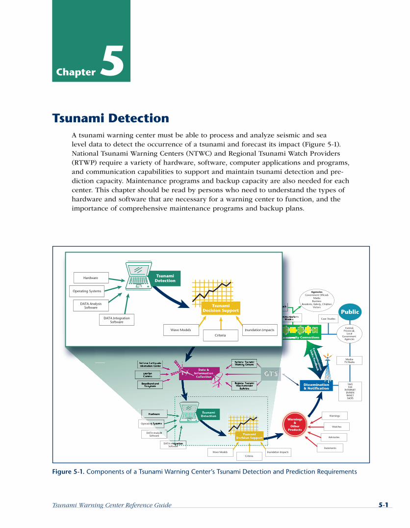
Tsunami Warning Center Reference Guide 5-1 Chapter 5 Tsunami Detection A tsunami warning center must be able to process and analyze seismic and sea level data to detect the occurrence of a tsunami and forecast its impact (Figure 5-1). National Tsunami Warning Centers (NTWC) and Regional Tsunami Watch Providers (RTWP) require a variety of hardware, software, computer applications and programs, and communication capabilities to support and maintain tsunami detection and pre- diction capacity. Maintenance programs and backup capacity are also needed for each center. This chapter should be read by persons who need to understand the types of hardware and software that are necessary for a warning center to function, and the importance of comprehensive maintenance programs and backup plans. Figure 5-1. Components of a Tsunami Warning Center’s Tsunami Detection and Prediction Requirements
-
Upload
trinhkhanh -
Category
Documents
-
view
218 -
download
0
Transcript of Tsunami Detection - MetEd » Home€¦ · Tsunami Detection Requirements for NTWCs and RTWPs? ......
Tsunami Warning Center Reference Guide 5-1
Chapter 5Tsunami Detection
A tsunami warning center must be able to process and analyze seismic and sea level data to detect the occurrence of a tsunami and forecast its impact (Figure 5-1). National Tsunami Warning Centers (NTWC) and Regional Tsunami Watch Providers (RTWP) require a variety of hardware, software, computer applications and programs, and communication capabilities to support and maintain tsunami detection and pre-diction capacity. Maintenance programs and backup capacity are also needed for each center. This chapter should be read by persons who need to understand the types of hardware and software that are necessary for a warning center to function, and the importance of comprehensive maintenance programs and backup plans.
Figure 5-1. Components of a Tsunami Warning Center’s Tsunami Detection and Prediction Requirements
GLOSS Tide GageNetworks
Local Tide GageNetworks
Local SeismicNetworks

5-2 Tsunami Warning Center Reference Guide
Chapter 5: Tsunami Detection
How Does Tsunami Detection Fit into an End-to-End Tsunami Warning System?
A tsunami warning center functions on a day-to-day basis in a manner similar to a seismological observatory. The center should strive to do two things as fast as pos-sible. First, the center must locate any moderate sized or larger earthquake in its area of responsibility (AOR) and assess its magnitude. Once that is accomplished, the center can begin to assess any potential tsunami threat to the regions in its AOR. If the earthquake poses a tsunami hazard, then the watch standers look for evidence of tsunami activity using an extensive network of tide gages, and ideally, tsunameters, at the center’s disposal. The capacity to detect a tsunami signal and predict its impact requires both scientific expertise and on-the-job experience in order to make quick decisions and issue products in a short period of time, especially for local tsunamis (Figure 5-2). For this reason, a tsunami warning system cannot be fully automated.
Compared to local tsunami events, more time is available for issuing bulletins for tele-seismic (originate more than 1000 kilometers away) events, as shown in Figure 5-3(minutes instead of seconds). Both timelines illustrate, however, the critical need for the center to have reliable, redundant communications channels and effective com-puter applications for collecting, processing, and displaying data, and creating and disseminating voice and text bulletins. To meet these requirements a center needs hardware (networks, workstations) and computer programs (operating systems, applications).
Analyzing and displaying earth data for watch standers is the core of the hazard detection and forecast component of an end-to-end tsunami warning system. The rapid detection and characterization of tsunami-generating earthquakes by com-puter applications programs provides the first indication of a potential tsunami in an
Figure 5-2. Timeline for Issuance of a Tsunami Bulletin for a Local Tsunami (in Seconds) (Adapted from the Pacific Tsunami Warning Center Operating Plan)

Tsunami Warning Center Reference Guide 5-3
Chapter 5: Tsunami Detection
end-to-end tsunami warning system. Initial seismic-based warnings based on data from networks of seismic gages are subsequently refined by the detection of tsunami-generated changes in sea level, measured by tide gages and buoys and analyzed by applications programs. The refinement of initial seismic-based warnings with data on sea level changes can greatly increase the credibility of the warnings by decreasing false alarms.
Critical seismic and sea level data must be received and processed rapidly at tsunami warning centers to be of any use in the warning process. Thus, data collection com-munications systems are crucial to the success of the warning system.
What Is in this Chapter?This chapter contains sections that discuss the following topics:
Information technology (IT) networks required by centers. This includes Wide Area Networks (WAN) for center connection to far-flung data gathering networks, and Local Area Networks (LAN) for analyzing and integrating data into display systems and computer models.
Operating systems and hardware (workstations) that are available for use at NTWCs and RTWPs.
Applications programs needed to collect, analyze, integrate, and display data at centers.
Maintenance program requirements for NTWCs and RTWPs
Redundancy programs and their importance.
Figure 5-3. Timeline for Bulletin Issuance for a Teletsunami Event (in Minutes)
5-4 Tsunami Warning Center Reference Guide
Chapter 5: Tsunami Detection
What Are the Most Important Points to Remember about Tsunami Detection Requirements for NTWCs and RTWPs?
Tsunami warning centers require a variety of hardware, software, computer appli-cations programs, and communications capabilities to process and analyze seismic and sea level data and detect the occurrence of a tsunami.
Computer programs that analyze and display earth data for watch standers are the core of the hazard detection and forecast component of an end-to-end tsunami warning system.
Critical seismic and sea level data must be received and processed rapidly at tsu-nami warning centers to be of any use in the warning process.
The capacity to detect a tsunami signal and predict its impact requires both sci-entific expertise and on-the-job experience in order to make quick decisions and issue products in a short period of time.
Information Technology RequirementsAn NTWC or RTWP requires computer power to effectively collect, process, moni-tor, and display seismic and sea level data and produce and disseminate products. This generally means that a tsunami warning center requires one or more connec-tions to distant networks, notably the internet. This effectively makes the center part of one or more WANs. Much of the information on WANs and LANs comes from the Wikipedia article http://en.wikipedia.org/wiki/Local_area_network for LANs and http://en.wikipedia.org/wiki/Wide_area_network for WANs and is licensed under the GNU Free Documentation License.
Wide Area Networks (WAN)A WAN is a computer network covering a broad geographical area, in contrast to a local area network (LAN), which is usually limited to a room, building, or campus. The largest and best-known example of a WAN is the internet.
WANs are used to connect LANs together so that users and computers in one loca-tion can communicate with users and computers in other locations. Many WANs are built for one particular organization and are private. Others, built by Internet service providers, provide connections from an organization’s LAN to the internet. WANs are most often built using leased lines. At each end of the leased line, a router connects to the LAN on one side and a hub within the WAN on the other. Leased lines can be very expensive. Instead of using leased lines, WANs can also be built using less costly circuit switching or packet switching methods. Network protocols including Trans-mission Control Protocol/Internet Protocol (TCP/IP) deliver transport and addressing functions. Protocols including Packet over SONET/SDH, MPLS, ATM and Frame relay are often used by service providers to deliver the links that are used in WANs.

Tsunami Warning Center Reference Guide 5-5
Chapter 5: Tsunami Detection
A WAN generally requires the crossing of public right-of-ways, and relies at least in part on circuits provided by a common carrier. Typically, a WAN consists of a number of interconnected switching nodes. A transmission from any one device is routed through these internal nodes to the specified destination device. These nodes (includ-ing the boundary nodes) are not concerned with the contents of data; rather, their purpose is to provide a switching facility that will move the data from node to node until they reach their destination. Several different options are available for WAN con-nectivity, as shown in Table 5-1.
Table 5-1. Various Wide-Area Network Connectivity Options
Options Description AdvantagesDis-advantages
Bandwidth Range
Sample Protocols Used
Leased line Point-to-point connection between two computers
Most secure Expensive Point to Point Protocol,
High Level Data Link Control
Synchronous Data Link Control
Circuit switching
A dedicated circuit path is created between end points. Best example is a dialup connection.
Call Setup 28 Kb/s–144 Kb/s
Point to Point Protocol,
Integrated Services Digital Network
Packet switching
Devices transport packets via a shared single point-to-point or point-to-multipoint link across a carrier inter-network. Variable-length packets are transmitted over Permanent Virtual Circuits or Switched Virtual Circuits.
X.25 Frame-Relay
Cell relay Similar to packet switching, but uses fixed-length cells instead of variable-length packets. Data is divided into fixed-length cells and then transported across virtual circuits.
Best for simultaneous use of voice and data
Overhead can be considerable
Asynchronous Transfer Mode

5-6 Tsunami Warning Center Reference Guide
Chapter 5: Tsunami Detection
Transmission rate usually ranges from 1200 bits per second to 6 megabits per second. Typical communication links used in WANs are telephone lines, microwave links, and satellite channels. Figure 5-4 shows is an example of a tsunami warning center’s WAN setup, depicting the West Coast/Alaska Tsunami Warning Center’s (WC/ATWC) con-nections to several WANs.
Local Area Network (LAN)NTWCs and RTWPs also require communication amongst several data monitoring, processing, and display computers via a LAN, a computer network covering a local area such as a home, office, or group of buildings. Current LANs are most likely to be based on switched IEEE 802.3 Ethernet running at 10, 100 or 1,000 megabits per second or on Wi-Fi technology.
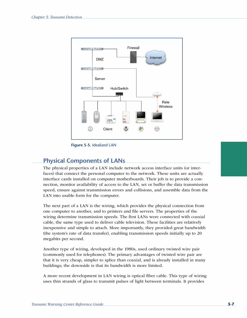
The defining characteristics of a LAN in contrast to a WAN are their much higher data rates and smaller geographic range, and that they do not require leased telecommu-nication lines. Figure 5-5 shows an example of an idealized LAN. Note that the LAN can include devices other than just personal computers (PC) or workstations, and it should have a firewall if connected to a public WAN like the internet.
Figure 5-4. WC/ATWC Connections to WANs
Tsunami Warning Center Reference Guide 5-7
Chapter 5: Tsunami Detection
Physical Components of LANsThe physical properties of a LAN include network access interface units (or inter-faces) that connect the personal computer to the network. These units are actually interface cards installed on computer motherboards. Their job is to provide a con-nection, monitor availability of access to the LAN, set or buffer the data transmission speed, ensure against transmission errors and collisions, and assemble data from the LAN into usable form for the computer.
The next part of a LAN is the wiring, which provides the physical connection from one computer to another, and to printers and file servers. The properties of the wiring determine transmission speeds. The first LANs were connected with coaxial cable, the same type used to deliver cable television. These facilities are relatively inexpensive and simple to attach. More importantly, they provided great bandwidth (the system’s rate of data transfer), enabling transmission speeds initially up to 20 megabits per second.
Another type of wiring, developed in the 1980s, used ordinary twisted wire pair (commonly used for telephones). The primary advantages of twisted wire pair are that it is very cheap, simpler to splice than coaxial, and is already installed in many buildings; the downside is that its bandwidth is more limited.
A more recent development in LAN wiring is optical fiber cable. This type of wiring uses thin strands of glass to transmit pulses of light between terminals. It provides
Figure 5-5. Idealized LAN

5-8 Tsunami Warning Center Reference Guide
Chapter 5: Tsunami Detection
tremendous bandwidth, allowing very high transmission speeds, and because it is optical rather than electronic, it is impervious to electromagnetic interference. Still, splicing it can be difficult and requires a high degree of skill. The primary applica-tion of fiber is not between terminals, but between LAN buses (terminals) located on different floors. As a result, fiber-distributed data interface is used mainly in building risers. Within individual floors, LAN facilities remain coaxial or twisted wire pair.
When a physical connection cannot be made between two LANs, such as across a street or between buildings, microwave radio may be used. However, it is often dif-ficult to secure frequencies for this medium. Another alternative in this application is light transceivers, which project a beam of light similar to fiber optic cable, but through the air rather than over cable. These systems do not have the frequency allo-cation or radiation problems associated with microwave, but they are susceptible to interference from fog and other natural obstructions.
LAN TopologiesLANs are designed in several different topologies, or physical patterns to depict con-nections between terminals. These connection patterns can range from straight lines to a ring. Each terminal on the LAN contends with other terminals for access to the system. When it has secured access to the system, a terminal broadcasts its message to all the terminals at once. The message is picked up by the one or group of termi-nal stations for which it is intended. The branching tree topology is an extension of the bus (shared communications line), providing a link between two or more buses.
A third topology, the star network, also works like a bus in terms of contention and broadcast. But in the star, stations are connected to a single, central node (individual computer) that administers access. Several of these nodes may be connected to one another. For example, a bus serving six stations may be connected to another bus serving 10 stations and a third bus connecting 12 stations. The star topology is most often used where the connecting facilities are coaxial or twisted wire pair.
The ring topology connects each station to its own node, and these nodes are con-nected in a circular fashion. Node 1 is connected to node 2, which is connected to node 3, and so on, and the final node is connected back to node 1. Messages sent over the LAN are regenerated by each node, but retained only by the addressees. Eventually, the message circulates back to the sending node, which removes it from the stream.
Transmission Methods Used by LANsLANs function because their transmission capacity is greater than any single termi-nal on the system. As a result, each station terminal can be offered a certain amount of time on the LAN, like a timesharing arrangement. To economize on this small window of opportunity, stations organize their messages into compact packets that can be quickly distributed. When two messages are sent simultaneously, they could collide on the LAN, causing the system to be temporarily disrupted. Busier LANs

Tsunami Warning Center Reference Guide 5-9
Chapter 5: Tsunami Detection
usually utilize special software that virtually eliminates the problem of collisions by providing orderly, “no contention” access.
The transmission methods used on LANs are either baseband or broadband. The baseband medium uses a high-speed digital signal consisting of square wave DC volt-age. While it is fast, it can accommodate only one message at a time. As a result, it is suitable for smaller networks where contention is low. It also is very simple to use, requiring no tuning or frequency discretion circuits. This transmission medium may be connected directly to the network access unit and is suitable for use over twisted wire pair facilities.
By contrast, the broadband medium tunes signals to special frequencies, much like cable television. Stations are instructed by signaling information to tune to a specific channel to receive information. The information within each channel on a broad-band medium may also be digital, but they are separated from other messages by frequency. As a result, the medium generally requires higher capacity facilities, such as coaxial cable. Suited for busier LANs, broadband systems require the use of tuning devices in the network access unit that can filter out all but the single channel it needs.
The File ServerThe administrative software of the LAN resides in a dedicated file server, or in a smaller, less busy LAN in a PC that acts as a file server. In addition to performing as a kind of traffic controller, the file server holds files for shared use in its hard drives, administers applications such as the operating system, and allocates functions.
When a single computer is used as both a workstation and a file server, response times may lag because its processors are forced to perform several duties at once. This system will store certain files on different computers on the LAN. As a result, if one machine is down, the entire system may be crippled. If the system were to crash due to lack of capacity, some data could be lost or corrupted.
The addition of a dedicated file server may be costly, but it provides several advan-tages over a distributed system. In addition to ensuring access even when some machines are down, its only duties are to hold files and provide access.
Other LAN EquipmentLANs are generally limited in size because of the physical properties of the network, including distance, impedance, and load. Some equipment, such as repeaters, can extend the range of a LAN. Repeaters have no processing ability, but simply regener-ate signals that are weakened by impedance. Other types of LAN equipment with processing ability include gateways, which enable LANs operating dissimilar pro-tocols to pass information by translating it into a simpler code, such as American Standard Code for Information Interchange (ASCII). A bridge works like a gateway, but instead of using an intermediate code, it translates one protocol directly into

5-10 Tsunami Warning Center Reference Guide
Chapter 5: Tsunami Detection
another. A router performs essentially the same function as a bridge, except that it administers communications over alternate paths. Gateways, bridges, and routers can act as repeaters, boosting signals over greater distances. They also enable separate LANs located in different buildings to communicate with each other.
The connection of two or more LANs over any distance is referred to as a WAN. WANs require the use of special software programs in the operating system to enable dial-up connections that may be performed by a telephone lines or radio waves. In some cases, separate LANs located in different cities—and even separate countries—may be linked over the public network.
LAN DifficultiesLANs are susceptible to many kinds of transmission errors. Electromagnetic interfer-ence from motors, power lines, and sources of static, as well as shorts from corrosion, can corrupt data. Software bugs and hardware failures can also introduce errors, as can irregularities in wiring and connections. LANs generally compensate for these errors by working off an uninterruptible power source, such as batteries, and using backup software to recall most recent activity and hold unsaved material. Some sys-tems may be designed for redundancy, such as keeping two file servers and alternate wiring to route around failures.
Security problems can also be an issue with LANs. They can be difficult to manage and access because the data they use is often distributed between many different networked sources. In addition, many times this data is stored on several different work-stations and servers. Most companies have specific LAN administrators who deal with these issues and are responsible for the use of LAN software. They also work to back up files and recover lost files.
Important Points to Remember about IT NetworksA WAN is a computer network covering a broad geographical area. They are used to connect local area networks (LANs) together, so that users and computers in one location can communicate with users and computers in other locations.
A LAN is a computer network covering a local area, like a home, office, or group of buildings. LANs have much higher data rates, smaller geographic range, and do not require leased telecommunication lines like most WANs.
A LAN should have a firewall if connected to a public WAN like the internet.
TipTsunami warning
centers should make
sure that firewalls and
other security measures
are in place to protect
the integrity of their
networks.

Tsunami Warning Center Reference Guide 5-11
Chapter 5: Tsunami Detection
Operating System and Hardware Requirements for NTWCs and RTWPs
An NTWC or RTWP requires computers and computer operating systems to effec-tively collect, process, monitor, and display seismic and sea level data and produce and disseminate products. Currently there are two main choices for tsunami warning center hardware and operating systems, PCs with Windows or Mac OS X, and UNIX-based workstations. Each has its strengths and weaknesses. Each requires significant resources to maintain.
Operating SystemsCurrently the most appropriate network operating systems for a NTWC or RTWP utilizing PCs come from Microsoft. Microsoft’s PC operating system options include Windows NT Advanced Server and Windows for Workgroups, and more recently Windows XP.
UNIX computer workstation from vendors such as Sun Microsystems, Hewlett-Pack-ard, Silicon Graphics, Intergraph, NeXT and Apollo have historically used TCP/IP based networking. Although this market segment is now much reduced, the tech-nologies developed in this area continue to be influential on the internet and in both Linux and Apple/Macintosh operating system (Mac OS X) networking, and the TCP/IP protocol has now almost completely replaced Internetwork Packet Exchange (IPX), AppleTalk, NetBIOS Extended User Interface (NETBEUI) and other protocols used by the early PC LANs.
There are advantages and drawbacks to utilizing a Windows-based LAN. Similarly, there are pros and cons to implementing a UNIX/Linux-based LAN in an NTWC or RTWP environment. But in both instances there needs to be redundancy and atten-tion to security to ensure data availability and processing at all times.
WorkstationsThere are two basic types of “workstations” that can be used to perform necessary operations in a tsunami warning center, i.e., collect data, run applications, and dis-seminate products. True high end workstations are usually coupled with some variant of the UNIX operating system. PCs, on the other hand, usually run a version of Win-dows or Apple/Macintosh operating system (Mac OS X), although higher end PCs can now use Linux as the operating system.
Following the performance trends of computers in general, today’s average PC is more powerful than the top-of-the-line workstations of one generation before. As a result, the workstation market is becoming increasingly more specialized, since many complex operations that formerly required high-end systems can now be handled by general-purpose PCs. However, workstation hardware is optimized for high data throughput, large amounts of memory, multitasking, and multithreaded computing. In

5-12 Tsunami Warning Center Reference Guide
Chapter 5: Tsunami Detection
situations requiring considerable computing power, workstations remain usable while traditional PCs quickly become unresponsive.
PCs use components that are often at or near the cutting edge of technology. These days, workstations have changed greatly. Since many of the components are now the same as those used in the consumer market, the price differential between work-stations and consumer PCs is correspondingly much narrower than it once was. For example, some low-end workstations use CISC (complex instruction set computer) based processors like the Intel Pentium 4 or AMD’s Athlon 64 as their central pro-cessing units (CPU). Higher-end workstations still use more sophisticated CPUs such as Intel Itanium 2, AMD Opteron, IBM POWER, or Sun’s UltraSPARC, and run a vari-ant of UNIX, delivering a truly reliable workhorse for computing-intensive tasks. This makes deciding whether or not to purchase a true workstation very difficult for many organizations. Sometimes these workstation systems are still required, but many orga-nizations opt for the less-expensive, if more fault-prone, PC-level hardware. Either route has advantages and disadvantages, but will, in general, still do the jobs an NTWC or RTWP requires.
Under optimal conditions, all NTWCs and RTWPs would use the same hardware, operating systems, and applications programs. That way development, main-tenance, trouble shooting, and operations could be standardized and economies realized. The reality is the operating system and hardware chosen by a center is often dictated by institutional norms, staff skills and capabilities, and/or budget constraints.
The number of workstations needed for center operations depends on the hardware and operating system, the number of applications, the extent of communications, and the approach taken to ensure the redundancy of critical functions.
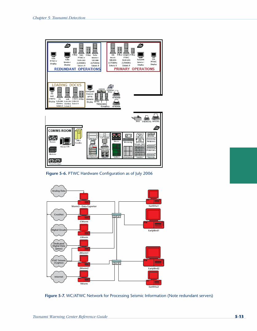
The Pacific Tsunami Warning Center (PTWC) utilizes UNIX Reduced Instruction Set Computer (RISC) workstations, and the core of operations consists of 6 Sun Micro-systems (SUN) computers. Two computers serve as loading docks. All seismic wave-form data and most of the parametric seismic data pass through the loading docks. Four workstations are used to process the seismic and sea-level data, and run other software such as travel-time computations and messaging software. The PTWC opera-tions are split into primary and redundant sides so as to avoid a single point of fail-ure. PTWC’s hardware configuration is shown in Figure 5-6.
WC/ATWC currently uses PCs running the latest Windows operating system. The center has two basic interconnected networks with redundant servers: “EarlyBird” for processing seismic events, and “tide” for sea level data. Figure 5-7 illustrates the basic topology for the WC/ATWC seismic network of ten Windows XP-based PCs that com-prise the EarlyBird seismic processing system. Five PCs import and export data using standard Earthworm modules. Two of the remaining PCs are the main and backup
TipNTWCs and RTWPs
should all strive to use
the same hardware,
operating systems, and
applications programs.
Tsunami Warning Center Reference Guide 5-13
Chapter 5: Tsunami Detection
Figure 5-6. PTWC Hardware Configuration as of July 2006
Figure 5-7. WC/ATWC Network for Processing Seismic Information (Note redundant servers)

5-14 Tsunami Warning Center Reference Guide
Chapter 5: Tsunami Detection
seismic data processors. Both constantly monitor earthquake activity on approximately 200 seismic channels. Each seismic processor has an associated PC that runs the EarthVu Geographic Information System (GIS). The GIS PCs display earthquake loca-tions processed on EarlyBird 1 and 2 and provide a graphical interface for database access. Many overlays of interest to the watch stander can be shown on the maps.
Important Points to Remember about Operating Systems and Hardware
Windows NT Advanced Server, Windows for Workgroups, and Windows XP are currently the most appropriate network operating systems for a NTWC or RTWP utilizing personal computers.
There are advantages and drawbacks to using a Windows-based LAN. Similarly, there are pros and cons to implementing a UNIX/Linux-based LAN in an NTWC or RTWP environment.
For both Windows and UNIX operating systems, redundancy and attention to security are needed to ensure data availability and processing at all times.
It would be optimal if all NTWCs and RTWPs used the same hardware, operating systems, and applications programs. That way development, maintenance, trouble shooting, and operations could be standardized and economies realized.
Computer Applications and Processing Requirements for NTWCs and RTWPs
Computer programs (applications) are critical to watch stander success at maintain-ing situational awareness. Applications can also provide processed information from earth data observations for input to decisions on what products the tsunami warning center needs to issue following an earthquake. The requirements for rapid character-ization of earthquakes and determination of tsunami threat include processing speed, sufficient observation (both seismic and sea level) network density, and sufficiently short interrogation intervals.
ApplicationsApplications are groups of computer code that provide a tsunami warning center’s watch stander with the tools needed to maintain situational awareness, collaborate, make deci-sions, prepare products, and disseminate these products in a timely fashion. In other words, applications help the watch stander do the required job, and most of these appli-cations are critical to getting the job done. The center’s operating system usually dictates what form the applications take, for example, Tool Command Language/Tool Kit (Tcl/Tk) for UNIX-based systems, and C++ for Windows-based systems. Experience at estab-lished NTWCs suggests that applications can be divided into several categories:
Collect seismic and sea-level data in real time
Process and database data in real time

Tsunami Warning Center Reference Guide 5-15
Chapter 5: Tsunami Detection
Automatically monitor data for exceeding criteria thresholds
Compute parameters that must be derived from observed data
Display data and information for the watch stander to maintain situational awareness
Disseminate text and graphic products to customers and other tsunami watch centers
While each center may utilize applications developed elsewhere, or develop their own on site, following are some applications that have been found to be needed. Some of the programs are elaborated upon in greater detail in the PTWC and WC/ATWC operations manuals.
Collect Seismic and Sea-level Data in Real TimeSea-level data are normally collected from international networks via the World Meteorological Organization’s (WMO) Global Telecommunications System (GTS), the internet, or a country’s WAN. Seismic data applications generally utilize internet com-munications and standard modules from the U.S. Geological Survey’s (USGS) Earth-worm program. These applications are:
Digitize analog data (although now done mostly in the field)
Receive data from the Incorporated Research Institutions for Seismology’ Interna-tional Deployment of Accelerometers (IRIS/IDA) network into Earthworm
Gather hypocenter and trace data from other centers
Start and restart all modules when necessary
Process and database data in real timeLog hypocenters to disk and EarthVu
Process surface wave data for moment magnitude (Mw) and mantle magnitude (Mm)
Process data for moment tensor
Auto-monitor data for exceeding criteria thresholdsRead, display, and analyze seismic data
Archive data
Call earthquake and tsunami databases
Read, display, and analyze tide gage and Deep Ocean Assessment and Reporting of Tsunami (DART) buoy readings
Read, display, and analyze run-up detection data
TipUSGS’s Earthworm is
a good program for
processing seismic data.
5-16 Tsunami Warning Center Reference Guide
Chapter 5: Tsunami Detection
Compute parameters that are derived from observed dataP-picking and magnitude determination algorithm
Interactively locate earthquake hypocenter
Trigger processing and compute Richter magnitude, surface magnitude (Ms), mantle magnitude (Mm), moment magnitude (Mw), p-wave moment magnitude (Mwp), etc.
Compute and display tsunami travel times
Display data and information for situational awarenessDisplay real-time, short period seismic data
Display computed hypocenter parameters and adjust P data
Display real-time, long period seismic data and process data for MS
Display location and P data to screen
Display earthquake summary to monitor
Display epicenters on large, small, and regional-scale maps
Overlay pertinent information such as historic tsunamis and earthquakes, volca-noes, elevation contours, roads, pipelines, and tsunami watch/warning areas
Display large-scale maps
Display small-scale maps
Display regional maps and show last 7 days’ epicenters
Create and display tsunami travel time maps triggered by tsunami message generation
Disseminate text and graphic products to customers and other centersSend hypocenter and trace data to other centers
Send alarm messages out from a serial port (for paging system)
Create tsunami warning and other messages based on earthquake hypocenter parameters
Create information maps in the background to post on website with tsunami messages
Create maps in background and write to disk for transfer to website
Automatically send emails to list of subscribers
Sea Level Data Processing RequirementsSeveral decades of experience at a number of national and regional centers have led to the determination of requirements for processing capabilities of sea level gage net-works to adequately support a tsunami warning program. Guidelines were developed
Tsunami Warning Center Reference Guide 5-17
Chapter 5: Tsunami Detection
by the Global Sea Level Observing System (GLOSS) program based on science princi-ples, and due to the compelling requirement to issue time-critical products to protect life and property. The following discussions are based on the very different needs of teletsunami and local tsunami warning programs. Each nation or jurisdiction will have to assess its needs in terms of early warning requirements.
The current specifications for the basin-wide (regional) in situ sea level component of tsunami warning systems requires data collection and transmission standards that include “sampling of 1 minute averages and a continuous 15 minute transmission cycle via WMO’s GTS to the JMA (Japan Meteorological Agency), PTWC, and other appropriate warning centers/watch providers.” These guidelines were developed in consultation with existing tsunami warning center scientists and technicians from PTWC and JMA, and with JMA and European Meteorological Satellite (EUMETSAT) geostationary satellite operators.
The Intergovernmental Oceanographic Commission (IOC) and GLOSS have been fol-lowing these guidelines in establishing and/or enabling sea level stations as part of the core network of sea level stations for the Indian Ocean Tsunami Warning System (IOTWS). However, subsequent Intergovernmental Coordination Group (ICG) meet-ings in Europe and the Caribbean and Concept of Operations (CONOPS) Team meet-ings identified the need for subregional and national data collection and transmission standards. The ICGs’ proposed standards include the following requirements:
Subregional sites (i.e., sites within 1 hour travel time of the tsunamigenic zones):
A sampling of 15-second averages, and a continuous transmission cycle of 5 minutes.
Immediate transmission via WMO’s GTS to JMA, PTWC, and other appropriate warning centers. (However, it is noted that the European and Japan geostation-ary meteorological satellites cannot be used since they are limited to a 15-minute transmission cycle.)
National sites (i.e., sites within 100 km of tsunamigenic areas):
A sampling of 15-second averages, and a continuous or 1-minute transmission cycle for sites within 100 km of the tsunamigenic zones.
Immediate transmission via WMO’s GTS to JMA, PTWC, and other appropriate warning centers and regional watch providers.
Standards should include data reports that cover a greater time period than the transmission frequency (to provide redundant data transmission).
Sea Level Data Processing SoftwareThe software package TideTool provides end users with the ability to decode, display, and manipulate sea-level data broadcast over WMO’s GTS. The software utilizes the Tcl/Tk software package, specifically the BLT extension. Tcl/Tk is an open source,
5-18 Tsunami Warning Center Reference Guide
Chapter 5: Tsunami Detection
platform-independent software package offering a powerful shell programming language and graphical toolkit.
The software application was developed by the PTWC to provide an operational tool for real-time, continuous tsunami monitoring in the Indian Ocean. Its primary users would be national meteorological and hydrological services, or other agencies with a downlink from the GTS or to a data file containing those data formatted in a similar
manner. It has been tested under Linux, Windows 2000, and Windows XP environ-ments in Indonesia and Malaysia. A manual is available providing information on its installation and use. Additional documentation on the program is available at: http://ioc3.unesco.org/ptws/documents/TWCOpsSeminar/InformationTools/SLdecode_display_summary2.doc.pdf
Seismic Data Network and Processing Requirements for Centers with a 5-Minute Response NeedTo produce accurate moment magnitudes, NTWCs and RTWPs require reliable, broad-frequency, low-noise, high-dynamic-range, digital seismic data in real time. The timeliness of the data is crucial to issuing an initial bulletin within 5 minutes of an earthquake. This is especially important for centers with local tsunami sources.
Seismic Network Data Density and Timing RequirementsTwelve evenly distributed seismometers within 900 km (2-minute P-wave travel time) of all coastal source areas.
Assume 80 percent data availability (9 to 10 sites operating at a time)
Up to 30 seconds of data latency
Above conditions will provide 9 to 10 P-wave observations within 2.5 minutes after the earthquake occurrence (or O-time). With an adequate processing system, a correct hypocenter location can be produced at this time.
60 seconds further to record the P-wave will provide data with which to compute a moment magnitude.
Moment magnitude and hypocenter available at 3.5 minutes after O-time.
30 seconds for experienced professional analyst review.
60 seconds to compose and send bulletin = 5 minutes total since O-time.
Seismic Data Processing CapabilitiesProcess seismic data to produce P-wave arrival times and appropriate magnitude parameters.
Trigger alarms based on strong ground shaking at a single station or pair of stations.
TipThe TideTool program is
a good application to use
for processing sea level
data.

Tsunami Warning Center Reference Guide 5-19
Chapter 5: Tsunami Detection
Produce immediate hypocenter locations given sufficient number of P arrivals (5 to 7 arrivals).
Support a graphical user interface which allows an analyst to review and alter data in real time and support relocation of events interactively.
Compute moment magnitude within 60 seconds of P-arrival for a given station.
Interact directly with product generation software to produce bulletins with mini-mal analyst effort.
Seismic Data Processing SoftwareThe USGS Earthworm seismic data processing system should be used as the base pro-cessing architecture for interoperability with other centers, availability of source code, and easy sharing of modules and processes. The Earthworm Version 7.1 User’s Guide can be found at: http://folkworm.ceri.memphis.edu/ew-doc/
Important Points to Remember about Applications and Processing Requirements
Experience at established tsunami warning centers suggests that required applications can be divided into several categories:
Collect, process, and database seismic and sea level data in real-time
Automatically monitor data for exceeding criteria thresholds
Compute parameters that must be derived from observed data
Display data and information for the watch stander to maintain situational awareness
Disseminate text and graphic products to customers and other centers
ICG and the CONOPS team identified the need for subregional and national data collection and transmission standards.
The software package TideTool provides end users with the ability to decode, dis-play, and manipulate sea level data broadcast over the WMO’s GTS.
The timeliness of seismic data is crucial to issuing an initial bulletin within 5 min-utes of an earthquake. This is especially important for centers with local tsunami sources.
The USGS Earthworm seismic data processing system should be used as the base processing architecture for interoperability with other centers.
Redundancy and Backup CapabilitiesAs discussed in the section on backup communications in Chapter 4, several types of backup systems should be used by tsunami warning centers. Alternate communica-tion paths for data collection and also for product dissemination are needed by each
5-20 Tsunami Warning Center Reference Guide
Chapter 5: Tsunami Detection
NTWC and RTWP. In the event of the failure of one of a center’s primary communica-tion links, information can be re-routed through a secondary connection. Similarly, centers should not rely on a single network or single gages, but utilize redundant net-works. Then if their primary earth data network is unavailable, either through equip-ment failure or communications problems, the center can still function using alternate networks.
Center functionality backup by another center means that procedures are in place for an RTWP to assume the functions of one of its NTWCs if that national center has lost all communications links. Similarly, each RTWP must have agreements in place for another RTWP to take over in the event of a catastrophic event at the disabled regional center. Typically, a tsunami warning center should have connections to at least two other centers, and each RTWP should have agreements with at least one other regional provider to provide backup communications.
Full backup capability by another center theoretically provides complete redundancy of the original center’s functions. There is, however, a high price for such a capability. The backup center must be trained in the other office’s procedures and responsibili-ties, and additional communications channels are usually needed if the backup center is to collect all pertinent data and reach all of the original center’s customers. And of course, the backup site staff must test backup procedures frequently.
Because of the high cost in both funds and resources, and the high probability of encountering problems due to the infrequency of use, full backup should be used only as a last resort. A center should strive to establish on-site redundancies in communications, hardware, and software so that it can continue to function in the event of a minor system outage.
As illustrated in Figures 5-6 and 5-7, hardware redun-dancy is an important requirement for a center. This hardware redundancy goes hand in hand with the need for a center to redundantly obtain seismic and sea level data from several different networks, and via several different communications channels. Redundancy helps to ensure that the data for applications programs will be available when most needed—during an event. As an added bonus, the backup system can also be configured as a training tool.
Important Points to Remember about Redundancy and Backup Operations
Full backup capability by another center theoretically provides complete redun-dancy of the original center’s functions and should be established.
TipAvoid invoking full
backup by creating
redundant
• communications,
• hardware, and
• software systems.

Tsunami Warning Center Reference Guide 5-21
Chapter 5: Tsunami Detection
Because of the high cost and high probability of encountering problems due to the infrequency of use, full backup should be avoided whenever possible, and each center should strive to establish on-site redundancies in communications, hard-ware, and software.
Maintenance RequirementsA well coordinated and supported maintenance program is critical to the success of a tsunami warning center. The breadth and depth of the maintenance program require-ments will depend on the types of equipment deployed by that center, and the extent to which the center maintains the equipment in-house. For example, if an NTWC needs to deploy its own seismic or sea level gages, then the training and knowledge set of the center’s electronics technicians will be different than those for a center that relies solely on international seismic or sea-level gage networks, or one whose national networks are maintained by another government agency or contractor. Simi-lar conditions exist for computer and communications hardware and software.
There are strong arguments favoring use of an in-house maintenance program versus relying on other groups to maintain critical equipment. The converse is also true; there are good arguments, especially with regard to budgets and redundancy of effort, for relying on “experts” to maintain the center’s critical equipment. One thing is clear, however: Tsunami warning centers require a good computer-based program for specifying, logging, and tracking critical equipment maintenance.
Whether a center operates with an in-house maintenance program, contracts out all maintenance, or has a program that is a mixture of the two approaches, it must track all maintenance activities in order to effectively manage the program. A center should establish an Engineering and Maintenance Reporting System (EMRS) similar to those used by many national meteorological agencies. The data collected by EMRS are vital to achieving maximum responsiveness to the center’s mission. EMRS should be the primary field-level-maintenance data collection, analysis, and maintenance-workflow management tool used by the center. EMRS data allow the center to:
Determine systems reliability and maintainability (R&M)
Anticipate systems and facilities maintenance requirements
Measure the effectiveness of systems and facilities upgrades and modifications
Provide configuration data for specific systems and facilities
Provide evidence of a system’s operational status for use in legal matters
Monitor engineering resources expended on designated systems and facilities
Provide program performance data
Manage maintenance workflow at the center
5-22 Tsunami Warning Center Reference Guide
Chapter 5: Tsunami Detection
Assess systems and facilities maintenance requirements, and assist in planning for future staffing levels
A center should establish what constitutes reportable maintenance events. These are events that should be tracked in order to maintain the center’s programs. In general, there are five types of reportable maintenance events:
Corrective Maintenance. The remedial action to correct failures and restore system/equipment or facility operation to prescribed capabilities and tolerances. This includes unplanned and nonperiodic repairs, as well as systems adminis-tration performed as a result of evidence indicating a failure has occurred or is imminent.
Equipment Management. The accomplishment of system, equipment, or facilities activation, deactivation, relocation, and other similar activity.
Modification. The authorized hardware and/or software configuration changes required to improve or extend system, equipment, or facility operations or life, or to satisfy new requirements.
Special Activity. The authorized short-term or limited collection of data (special sampling), system or equipment installation, equipment relocation, equipment modification system test, and other similar activity for a specific purpose.
Preventive/Routine Maintenance. Maintenance actions performed on system, equipment, or facilities to ensure continued operation within the prescribed capa-bilities or to minimize failure probability. Routine maintenance includes sched-uled, planned, or periodic preventive maintenance actions.
An EMRS program is essential to maintaining critical equipment, setting staffing levels, and formulating budgets.
Software MaintenanceMost software maintenance will fall into a few general categories:
Loading commercial software, including operating systems and applications.
Keeping current commercial software (operating systems and applications) up to date. This includes loading interim patches.
Assisting local programmers in developing, debugging, and maintaining staff authored computer programs, and distributing such programs to other centers.
Adapting software applications from other NTWCs and RTWPs to fit center needs, and possibly improving the application for distribution to other centers.
Hardware MaintenanceHardware maintenance can involve work on any of the following systems, depend-ing on the center’s maintenance program philosophy and goals (for example, whether

Tsunami Warning Center Reference Guide 5-23
Chapter 5: Tsunami Detection
maintenance is in-house or contracted). While this list is not exhaustive, it illustrates the wide range of skills needed by the electronics staff at a center:
Seismometers
Tide gages
DART buoys
PCs (operational and administrative)
RISC workstations
Servers
Routers
Cabling
Firewalls
Telephone systems, including answering machines
Satellite uplinks and downlinks
UHF and VHF links
HAM radio transmitters
Electronics Technician TrainingElectronics technicians must be proficient in at least three very distinct areas:
Mechanical devices (e.g., tide gages)
Electronic devices, including microelectronics
Software
International training is available for both tide gage and seismometer installation and maintenance (see below). Training in software applications, including operating systems and programming, is also readily available and should be utilized whenever possible.
Training on other electronic devices like routers, satellite downlinks, and HAM radio transmitters is more difficult to obtain but should be budgeted for, as these types of systems are crucial to center operations.
SeismometersIn July 2003 the USA National Science Foundation released a report titled, “Review of the Global Seismographic Network.” In this review it was stated that “the Review Committee is obliged and pleased to note that this community enterprise, the GSN, has been an extraordinary success. The establishment of a high-quality global digital

5-24 Tsunami Warning Center Reference Guide
Chapter 5: Tsunami Detection
network has been achieved, and it now serves as the primary source of data for seis-mologists worldwide.”
The sensor of choice has been the STS-1, with the KS-54000I an acceptable alternate. Both sensors have yielded high quality data, but the STS-1 has a significantly broader band of response. The future availability of the STS-1, however, is in question for two reasons:
(a) The high quality and uniformity of the sensor depends on the personal skill of the designer/assembler, who has intimated that he no longer wishes to build the instrument.
(b) The original supply of fabrication material is nearly exhausted, and the uniformity depends in part on use of this common material.
As the GSN begins a decade of O&M, sensor failure will become more common. The question arises as to where replacement STS-1 instruments can be obtained, and ulti-mately whether a suitable replacement for the STS-1 can be developed. One possibil-ity is to close poorly performing stations and recycle their instruments; another is to purchase spare instruments from other networks with surplus equipment. But in the long run, a replacement broadband sensor needs to be developed.
With the above caveats it becomes evident that the decision for a NTWC to field some of their own seismometers is not clear cut. In the short term the existing networks will likely meet TWS needs, except in oceanic regions where the network is currently sparse or non-existent, and underwater landslides are a significant threat. An exam-ple of this situation is the Hawaiian Islands, where the State of Hawaii and PTWC have installed additional seismometers. Longer term needs will depend largely on the future actions of those operating the international networks.
If a NTWC opts to augment existing networks with their own deployed and main-tained seismometers there are numerous references to assist the Center in the endeavor. One such document is a USA USGS publication “Methods of Installing United States National Seismographic Network (USNSN) Stations—A Construction Manual, Open-File Report 02-144 2002.” The USGS has learned that after many years of network operation some of the important design features of the US National Seis-mograph Network include:
Use of off-the-shelf electronic equipment when possible;
The ability to install a seismic station in diverse environments;
A physically protective, dry, and thermally stable environment for the broadband sensors;
An overall station design that is easy to maintain;
Manageable installation costs.
Tsunami Warning Center Reference Guide 5-25
Chapter 5: Tsunami Detection
Further guidance for NTWCs to deploy seismic stations is given by the IRIS GSN Design Goals Subcommittee Report—Global Seismic Network Design Goals Update August 26, 2002.
In addition to training material for seismic installations from the USA USGS and other governments, sensor manufactures offer model specific training. For example, Guralp Corporation offers maintenance training at http://www.guralp.com/services/training/bsctrouble.htm, where they break down maintenance into electronics and mechanics.
The Public Seismology Network website (http://psn.quake.net) has posted manuals for several popular types of seismograph equipment. These are:
Teledyne/Geotech BB-13 Long Period Sensor Operator and Maintenance Manual
Sprengnether MEQ800 Portable Seismic System Technical Manual
Instructions for Construction of a Lehman Seismometer by Kelly Knight
Tide GagesInternational tide gage networks are coordinated by UNESCO-IOC. Data and train-ing are administered by several sources, notably the Permanent Service for Mean Sea Level (PSMSL) of the Proudman Oceanographic Laboratory (POL), UK, which is acces-sible at http://www.pol.ac.uk/psmsl/. The applicable tide gage materials are IOC Manuals and Guides No. 14: Volumes I– IV.
Volumes I– IV comprise the IOC Manual on Sea Level Measurement and Interpreta-tion. Volume I (Basic Principles) was published in 1985 and is based on training courses held at the Proudman Oceanographic Laboratory (POL) on behalf of the PSMSL and IOC. It contains information on the scientific aspects of sea level change and on practical aspects of sea level measurement and data reduction. Volume II (Emerging Technologies) was published in 1994 and is complementary to the earlier volume, extending and updating the material on measurements.
In the late 1990s, it was realized that the contents of Volumes I– II were beginning to show their age and so Volume III was constructed and finally published in 2000. A much larger Volume IV followed in 2006. However, note that Volumes I– III are still useful, and still provide the basic sets of information for people intending to install and operate tide gauges.
Manuals I– IV are available in both paper and electronic forms. For paper versions, email [email protected]. Electronic versions are provided at http://www.pol.ac.uk/psmsl/ as PDF files.
Volume I: Basic Procedures
Volume II: Emerging Technologies
5-26 Tsunami Warning Center Reference Guide
Chapter 5: Tsunami Detection
Volume III: Reappraisals and Recommendations as of the year 2000
Volume IV: An update to 2006
Several updates to sections of the older manuals are also available e.g.:
List of tide gage manufacturers (updated from Vols. 1 and 2).
Glossary of terms used in tidal measurements and analysis (updated from Vol. 1).
Frequently used abbreviations and acronyms (updated from Vol. 1).
GLOSS (or GLOSS-related) training courses have been held a rate of approximately one per year since 1983. These have been held in all continents and in all languages, with the majority of the first courses held at the Proudman Oceanographic Labora-tory. For people unable to attend courses, most of the training materials employed in a typical course are available on the web at the PSMSL training page (http://www.pol.ac.uk/psmsl/training/training.html).
Another source of documentation on tide gage installation, maintenance, and use is from the website: http://www.icsm.gov.au/tides/SP9/index.htm which provides access to the Australian Tides Manual Special Publication No. 9.
Important Points to Remember about Maintenance Programs for Tsunami Warning Systems
The need for a well coordinated and supported maintenance program is critical to the success of NTWCs and RTWPs.
Whether a center operates with an in-house maintenance program, contracts out all maintenance, or has a program that is a mixture of the two approaches, it must track all maintenance activities in order to effectively manage the program.
A center should establish what constitutes reportable maintenance events. These are events that should be tracked in order to maintain the center’s programs.
There is international training available for both tide gage and seismometer installation and maintenance.
Training on other electronic devices like routers, satellite downlinks, and HAM radio transmitters are more difficult to obtain, but should be budgeted for as these types of systems are crucial to center operations.