Tsn lecture vol 2
49
TSN Lectures ETE 310 Prof. A.H.M. Asadul Huq, Ph.D. http://asadul.drivehq.com/students.htm [email protected] Sunday, March 13, 202 2 A.H. 1 Introduction to Switching
-
Upload
musfiqsvn -
Category
Technology
-
view
35 -
download
2
Transcript of Tsn lecture vol 2

TSN LecturesETE 310
Prof. A.H.M. Asadul Huq, Ph.D.http://asadul.drivehq.com/students.htm
April 18, 2023 A.H. 1
Introduction to Switching

Introduction to Switching
• A switching system connects a call from one subscriber to the desired subscriber.
• One important problem is how to manage traffic within the switching system.
• In early telephone network, operators in the switching office used to connect subscribers manually.
April 18, 2023 A.H. 2

Introduction to Switching … continued
• Switching and other relevant techniques have been evolved to automatic telephone exchanges where digital controls have been used.
• If no circuit is available to connect to the desired subscriber, the call will be blocked.
• When a call is finished the connection will be disconnected to make the circuit available for other users.
April 18, 2023 A.H. 3
Switching technology types
In general, two different types of technologies of switching -• Circuit Switching• Packet Switching
April 18, 2023 A.H. 4
Circuit Switching Packet Switching

Circuit Switch Network
Circuit switch network assigns a dedicated communication path (physical and real time) between 2 stations. It involves -• Direct connection from a station to network• Internal switching (and multiplexing) among
switching nodes.• Communication• Circuit physically disconnection.
April 18, 2023 A.H. 5

Advantages and disadvantages of Circuit-Switched Network
Advantages• Once connection is established network is transparent.• Nodes seem to be directly connected.• Fixed communication rate with no delay
Disadvantages• Can be inefficient• Resources are dedicated to the connection even if no data is
sent• Delay (for set up) prior to usage of connection• Probability of blocking for voice connection.
April 18, 2023 A.H. 6

Comparison
April 18, 2023 A.H. 7

April 18, 2023 A.H. 8

Elements of Switching System
• Switching network subsystem• Signaling subsystem• Control subsystem• Accessory circuit
April 18, 2023 A.H. 9
Direct Control vs Common Control• If the control subsystem is an integral part of the switching
network then the system is called direct control switching systems.
• If the control subsystem is outside the switching network then the system is called common control switching system.
Examples• Strowger exchanges are usually direct control system.• Crossbar and electronic exchanges are common control
system.• All stored program control systems are common control
system.
April 18, 2023 A.H. 10

Direct v Common Control Signaling
April 18, 2023 A.H. 11

Signaling
Signaling help exchanges to establish connections between subscribers correctlySignal category.• Subscriber loop signaling.• Inter-exchange signaling.• Intra-exchange or register signaling.
April 18, 2023 A.H. 12

Telephone subscriber loop signaling
April 18, 2023 A.H. 13

The Terminology for exchange units
April 18, 2023 A.H. 14

Remember this very basic point to point network
April 18, 2023 A.H. 15
• There are n stations (in this case n= 6).
• Each station needs lines to n-1 others.
• All stations can call every other stations. No blocking.
• The system needs a total number of interconnecting lines -

April 18, 2023 A.H. 16
The N2 ProblemFor N users to be fully connected directly• Requires N(N – 1)/2 connections • Requires too much space for cables• Inefficient & costly since connections are not always on
N = 1000N(N – 1)/2 = 499500
1
2
34
N
. . .
Solution: Use a telephone switching exchange office where efficient switching will be performed

Manual switching Exchange Office• Patch cord panel switch invented in 1877• Operators connect users on demand
– Establish circuit to allow electrical current to flow from inlet to outlet
• Only N connections required to the exchange
1
23
N – 1
N
April 18, 2023 A.H. 17

April 18, 2023 A.H. 18
Strowger Switch• Human operators are intelligent & flexible
– But expensive– Possibility of human error– Less switching speed
• Strowger invented automated switch in 1888– Dialer is included in the telephone set– Telephone user at home now send dial pulses to
the exchange and controls connection setup – no manual operator needed
– Each current pulse produced by the dialing phone at home advances the wiper of the Strowger switch by 1 position at telephone exchange

Almon Brown StrowgerFather of the automatic telephone switching system
• A B Strowger invented automatic telephone exchange. He was awarded a patent in 1891.
• Bell Telephone Company acquired the technology in 1916 and it was called Strowger Switch, became standard equipment throughout the 20th century.
April 18, 2023 A.H. 19
Almon Brown Strowger1839 - 1902

Basic Strowger switching components
2 types –• Uniselector• two motion selector
April 18, 2023 A.H. 20

Strowger two motion step by step Switch
April 18, 2023 A.H. 21
The movable contacts in a step by step Strowger switch can connect to any of a 100 different pairs of fixed contacts, each leading to a different line.

Timeline of TelecommunicationSource: www.telephonetribute.com/timeline.html
April 18, 2023 A.H. 22

Multiple stage switching
• Decimal telephone numbering system• multiple switching stages• Hierarchical network structure simplifies call
connection– Area code, exchange, station number can be
assignedApril 18, 2023 A.H. 23
.
.
.
0
9
0
9...
0
9
0
9
.
.
.
1st digit 2nd digit . . .

Model of Switching Network
Switching network is a component of the switching systemMain function: Establish an electrical path between given inlet/outlet pair (2 telephone users or subscribers)
April 18, 2023 A.H. 24

Inlets/outlets Connections
• Types of connections• Local call (Incoming and outgoing)• Trunk (transit) call (call between 2 subscribers of
2 separate exchanges)
April 18, 2023 A.H. 25

Folded network
• All inlet/outlets are connected to the subscriber lines.• This is only for local exchange.
April 18, 2023 A.H. 26
EXCHANGE
1
N

Blocking and Non-blocking System
• Non-blocking: A calling subscriber will always be able to establish a connection to the called subscriber
• Blocking: Not all subscriber will be able to call to a desired subscriber all time. The reason is that the number of simultaneous switching paths are less than the total number of subscriber in a system.
April 18, 2023 A.H. 27
Note: All switching exchanges are designed to meet an estimated maximum average simultaneous traffic, usually known as busy hour traffic. Past records of the telephone traffic indicate that even in a busy exchange, not more than (20-30)% of the subscribers are active at the same time.

Elements of a telephone exchange
April 18, 2023 A.H. 28

Switching Techniques (Review)• Circuit Switching
– A path is established between the caller and destination.– Real-time connection formed.– Example: PSTN
• Message Switching– Also called store and forward.– A message is first stored in a buffer and then sent on in its entirety
step by step as resources become available.– No real-time connection (i.e. connectionless).– Example: E-mail
• Packet Switching– A message is broken down into parts and each part is sent separately
(possibly via different routes).– Example: Internet UDP protocol
April 18, 2023 A.H. 29

Switching Circuits• Four technologies for separating (Switching) circuits:
– Space, time, Radio frequency, Optical• We want to connect circuits coming into a switch with circuits
at the output.• Example of Space division switch: Strowger, crossbar Switch.• Example “space division” equivalent interconnection pattern:
Input 1
Input 2
Input 3
Output 1
Output 2
Output 3
April 18, 2023 A.H. 30

Space Division Switching• Connecting two channels that are separated in space.• Can be mechanical and/or electronic.• Several problems:
– Slow– Bulky with lots of interconnect wiring– Subject to cross-talk
Input 1
Input 2
Input 3
Output 1
Output 2
Output 3
Input 1
Input 2
Input 3
Output 1
Output 2
Output 3
Equivalent
April 18, 2023 A.H. 31

Strowger Switching• Patented 12/March/1889 and in some places still in use
today.• First widely-used automatic exchange system.• A wiper assembly (contact arm) moves across a fixed set
of switch contacts (contact bank).– Each contact is connected to an outgoing channel.
Uni-selector:
Strowgeruni-selector
April 18, 2023 A.H. 32

Strowger Switching (2)
• Several uni-selectors can be “graded” together so multiple incoming circuits can connect to multiple outgoing circuits.
• Or two uni-selectors can be wired back-to-back (line-finders).– 1st uni-selector chooses the incoming circuit, the 2nd chooses the
outgoing circuit.
Graded uni-selectors:
Unless there is heavy traffic, it is inefficient and uneconomical to provide each incoming circuit with a uni-selector.
Line-finder (hunter):
Incoming Circuits
Outgoing Circuitsor otheruni-selectors
Line-finders can be graded together as well to form large switches.
April 18, 2023 A.H. 33
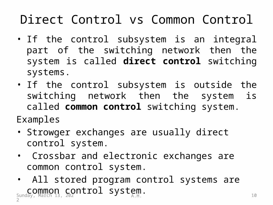
Strowger Switching (3) (Review)• In general, multiple uni-selectors, line-finders, and two-
motion selectors (movable in two planes) can be connected in series.
• These switches respond to dialled digits, automatically switching an incoming circuit to the correct outgoing trunk.– Step-by-step switching will respond to each digit
individually.
Strowger two-motion selector
April 18, 2023 A.H. 34

Two motion Selector (Trowger)
• A set of wipers (in the figure there is one wiper shown for simplicity) is moved in two different planes (horizontal and vertical, you have seen that in a video clip)
• A typical switch can access 100 switching contacts (10 vertical levels and each level contains 10 horizontal contact points).
Note: Actually there are 11 vertical positions and 11 horizontal contacts. The lowest vertical position and first horizontal position in each vertical level are home positions.
April 18, 2023 A.H. 35

Block diagram of a multi-stage Strowger switching system
• Subscriber Line circuit(SLC) and Line finder: When a subscriber lifts his handset, current starts to flow on the line, this is detected by SLC.
• Line finder and allotter finds a free selector. (see next figure)
April 18, 2023 A.H. 36

Routing of a local call in Strowger switching system
• Group selector: Depends on the subscriber number. For a 4 digit number two selectors are required.
• Final selector: The final selector takes care of last two digits.• If called subscriber is free the path setup is competed.
Otherwise a busy signal is retuned to the caller. (Gna P. 66-68)
April 18, 2023 A.H. 37

A Typical Public Circuit Switched Network (PSTN)
April 18, 2023 A.H. 38
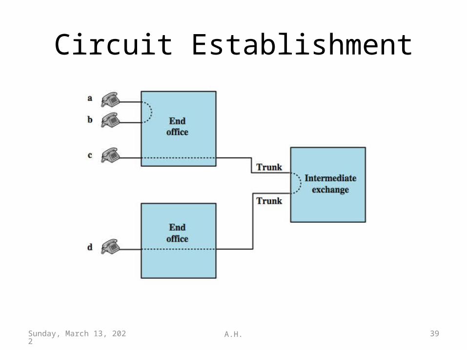
Circuit Establishment
April 18, 2023 A.H. 39

Multi-stage Space Division Switch
April 18, 2023 A.H. 40

Blocking or Non-blocking (Review)
• blocking network– may be unable to connect stations because all
paths are in use– used on voice systems
• non-blocking network– permits all stations to connect at once– used for some data connections .
April 18, 2023 A.H. 41

An example of Blocking
Even though there are free links throughout the switch, there is a conflict for specific links required for the brown connection.
5 x 5
5 x 5
5 x 5
5 x 5
5 x 5
5 x 5
5 x 5
5 x 5
5 x 5
5 x 5
5 x 5
5 x 5
5 x 5
5 x 5
5 x 5
• Analyze how blocking in a network occurs:– There are generally free links in each stage.– Problem is that they are mismatched from stage to stage.
So blocking occurs for this design.
April 18, 2023 A.H. 42

Design 1: 100 line switching system using uniselectors
• 100 subscriber. 2 stage Strowger exchange.
• This is a blocking design• Each subscriber should given one
uniselector at the exchange (100 uniselector at the inlet)
• Only 10 uniselector at the outlet• The corresponding outlets of all
the 1st stage uniselectors are commond or connected.
• Probability of blocking PB=0.009.• Equipment utilization factor EUF
= 0.18 • CCI = 9.09 (Thia P. 48-50)
April 18, 2023 A.H. 43

Design 2: 100 line exchange with two-motion selectors
• 100 subscriber. Single stage. Non blocking.• A subscriber is assigned a number in the range 00-99.• The corresponding outlets in all the 100 two-motion selectors are
commoned and folded back to the corresponding inlets.• Blocking probability PB = 0• Equipment utilization factor EUF = 0.5• CCI = 25 (Thia P. 51-52)April 18, 2023 A.H. 44

Switching Network Design Parameters1. Number of subscriber lines = N2. Total number of switching elements = S3. Cost of switching system C=SxCs +Cc+Cch
where, Cs=cost per switching systemCc=cost of the common control systemCch=cost of the common hardwareSince the control circuits are associated with switching elements in a Strowger system, Cc = 0 for the system.
The common hardware is usually a small proportion of the total hardware except for the power supplies and its cost is of the same order in different comparable designs. Hence we ignore it, hence Cch =0 in most of the calculations.
April 18, 2023 A.H. 45

Switching Network Design Parameters … continued4. Switching capacity = SC (Max no. of connections at a time)5. Traffic handling capacity-
6. Equipment utilization factor – 7. Number of switching stages = K8. Average switching time per stage Tst
9. Call setup time = Ts = (Tst x K) + To
To is time required for functions other than switching. To is significant quantity in Common Control Systems where control functions are separated from switching functions. In Strowger (direct control) systems, To may be considered 0.
April 18, 2023 A.H. 46

Switching Network Design Parameters … continued
10.Cost capacity index –
Higher the value of CCI, better the design.
April 18, 2023 A.H. 47

Design Parameters of the Design 1
• S=110, SC = 10, K=2, N=100• TC=2(SC/N)=2(10/100)=0.2• EUF = 20/110 = 0.18Cost =C=Total no. of switches x unit cost=110x1=110CCI= =(100x10)/110 = 9.09.
April 18, 2023 A.H. 48

TSN LectureVolume-2
THE END
THANK YOU
This ppt may be downloaded from my web site:http://asadul.drivehq.com/students.htm
Password (email address): [email protected]
This password does not live long !
April 18, 2023 A.H. 49