TS 183 043 - V2.3.1 - Telecommunications and Internet ... · PDF fileETSI 2 ETSI TS 183 043...
140
ETSI TS 183 043 V2.3.1 (2009-03) Technical Specification Telecommunications and Internet converged Services and Protocols for Advanced Networking (TISPAN); IMS - based PSTN/ISDN Emulation; Stage 3 specification
-
Upload
trinhxuyen -
Category
Documents
-
view
238 -
download
2
Transcript of TS 183 043 - V2.3.1 - Telecommunications and Internet ... · PDF fileETSI 2 ETSI TS 183 043...

ETSI TS 183 043 V2.3.1 (2009-03)
Technical Specification
Telecommunications and Internet converged Services andProtocols for Advanced Networking (TISPAN);
IMS - based PSTN/ISDN Emulation;Stage 3 specification

ETSI
ETSI TS 183 043 V2.3.1 (2009-03) 2
Reference RTS/TISPAN-03134-NGN-R2
Keywords IMS, ISDN, PSTN, stage 3
ETSI
650 Route des Lucioles F-06921 Sophia Antipolis Cedex - FRANCE
Tel.: +33 4 92 94 42 00 Fax: +33 4 93 65 47 16
Siret N° 348 623 562 00017 - NAF 742 C
Association à but non lucratif enregistrée à la Sous-Préfecture de Grasse (06) N° 7803/88
Important notice
Individual copies of the present document can be downloaded from: http://www.etsi.org
The present document may be made available in more than one electronic version or in print. In any case of existing or perceived difference in contents between such versions, the reference version is the Portable Document Format (PDF).
In case of dispute, the reference shall be the printing on ETSI printers of the PDF version kept on a specific network drive within ETSI Secretariat.
Users of the present document should be aware that the document may be subject to revision or change of status. Information on the current status of this and other ETSI documents is available at
http://portal.etsi.org/tb/status/status.asp
If you find errors in the present document, please send your comment to one of the following services: http://portal.etsi.org/chaircor/ETSI_support.asp
Copyright Notification
No part may be reproduced except as authorized by written permission. The copyright and the foregoing restriction extend to reproduction in all media.
© European Telecommunications Standards Institute 2009.
All rights reserved.
DECTTM, PLUGTESTSTM, UMTSTM, TIPHONTM, the TIPHON logo and the ETSI logo are Trade Marks of ETSI registered for the benefit of its Members.
3GPPTM is a Trade Mark of ETSI registered for the benefit of its Members and of the 3GPP Organizational Partners. LTE™ is a Trade Mark of ETSI currently being registered
for the benefit of its Members and of the 3GPP Organizational Partners. GSM® and the GSM logo are Trade Marks registered and owned by the GSM Association.

ETSI
ETSI TS 183 043 V2.3.1 (2009-03) 3
Contents
Intellectual Property Rights ..............................................................................................................................10
Foreword...........................................................................................................................................................10
1 Scope ......................................................................................................................................................11
2 References ..............................................................................................................................................11 2.1 Normative references .......................................................................................................................................12 2.2 Informative references......................................................................................................................................14
3 Definitions and abbreviations.................................................................................................................14 3.1 Definitions........................................................................................................................................................14 3.2 Abbreviations ...................................................................................................................................................15
4 IMS-based PSTN Emulation Subsystem (PES) overview .....................................................................16 4.1 General .............................................................................................................................................................16 4.2 URI and address assignments...........................................................................................................................17 4.3 AGCF and VGW session and registration processing model...........................................................................17 4.3.1 General........................................................................................................................................................17 4.3.2 Conventions ................................................................................................................................................18
5 Protocol using SIP and SIP events for PES............................................................................................19 5.1 Introduction ......................................................................................................................................................19 5.2 Functional Entities............................................................................................................................................19 5.2.1 User Equipment (UE) .................................................................................................................................19 5.2.2 Access Gateway Control Function (AGCF) ...............................................................................................20 5.2.3 Application Server (AS) .............................................................................................................................20 5.2.4 Media Resource Function Controller (MRFC) ...........................................................................................20 5.2.5 Media Gateway Controller Function (MGCF)............................................................................................20 5.2.6 Interconnection Border Control Function (IBCF).......................................................................................20 5.2.7 Voice over IP gateway (VGW) acting as Access Gateway ........................................................................20 5.3 Role ..................................................................................................................................................................21 5.3.1 PES Endpoint..............................................................................................................................................21 5.3.1.1 General ..................................................................................................................................................21 5.3.1.2 Subscription for profile delivery ...........................................................................................................21 5.3.1.3 Registration procedures.........................................................................................................................21 5.3.1.4 Charging procedures .............................................................................................................................22 5.3.1.5 Outgoing Call ........................................................................................................................................22 5.3.1.5.1 General ............................................................................................................................................22 5.3.1.5.2 Procedures for analogue lines..........................................................................................................22 5.3.1.5.3 Procedures for ISDN access ............................................................................................................22 5.3.1.5.4 Use of Overlap Signalling (Optional)..............................................................................................23 5.3.1.6 Terminating Call ...................................................................................................................................23 5.3.1.6.1 General ............................................................................................................................................23 5.3.1.6.2 Use of Overlap Signalling (Optional)..............................................................................................23 5.3.1.7 Supplementary services configuration ..................................................................................................23 5.3.1.7.1 Analogue lines .................................................................................................................................23 5.3.1.7.2 ISDN lines .......................................................................................................................................23 5.3.2 PES Access Point........................................................................................................................................24 5.3.2.1 General ..................................................................................................................................................24 5.3.2.2 Subscription for profile delivery ...........................................................................................................24 5.3.2.3 Registration Procedures ........................................................................................................................24 5.3.2.4 Originating Call Control procedures .....................................................................................................25 5.3.2.4.1 General ............................................................................................................................................25 5.3.2.4.2 Procedures for analogue lines..........................................................................................................26 5.3.2.4.3 Procedures for ISDN access ............................................................................................................26 5.3.2.4.4 Use of Overlap Signalling (Optional)..............................................................................................26 5.3.2.5 Terminating Call Control procedures....................................................................................................26 5.3.2.5.1 General ............................................................................................................................................26

ETSI
ETSI TS 183 043 V2.3.1 (2009-03) 4
5.3.2.5.2 Use of Overlap Signalling (Optional)..............................................................................................27 5.3.2.6 Charging procedures .............................................................................................................................27 5.3.2.7 Supplementary services configuration ..................................................................................................27 5.3.2.7.1 Analogue lines .................................................................................................................................27 5.3.2.7.2 ISDN lines .......................................................................................................................................27 5.3.3 PES Application Server ..............................................................................................................................27 5.3.3.1 General ..................................................................................................................................................27 5.3.3.2 Basic call procedures.............................................................................................................................28 5.3.3.3 Announcement procedures....................................................................................................................28 5.3.3.4 Profile Delivery.....................................................................................................................................28 5.3.3.5 Transport of ISUP information .............................................................................................................29 5.3.3.5.1 General ............................................................................................................................................29 5.3.3.5.2 Sending NSS message bodies to a peer SIP signalling entity..........................................................29 5.3.3.5.3 Receiving an NSS message body from a peer SIP signalling entity................................................31 5.3.3.6 Handling of charging information.........................................................................................................32 5.3.3.7 Supplementary services configuration ..................................................................................................32 5.3.4 PES Announcement Server.........................................................................................................................32 5.3.4.1 General ..................................................................................................................................................32 5.3.4.2 Announcement procedures....................................................................................................................32 5.3.5 PES Interworking Application....................................................................................................................32 5.3.5.1 General ..................................................................................................................................................32 5.3.5.2 Routing procedures ...............................................................................................................................33 5.3.5.3 Handling of charging information.........................................................................................................33 5.3.5.4 Transport of ISUP information .............................................................................................................33 5.3.5.4.1 General ............................................................................................................................................33 5.3.5.4.2 Sending ISUP information to a peer SIP signalling entity ..............................................................33 5.3.5.4.3 Receiving an NSS message body from a peer SIP signalling entity................................................35 5.3.5.4.4 ISUP messages for special consideration ........................................................................................36 5.3.5.5 Optional SIP/ISUP interworking procedures for PSTN Bridging.........................................................37 5.3.6 PES interconnection application .................................................................................................................38 5.3.6.1 General ..................................................................................................................................................38 5.3.6.2 Procedures related to NSS message bodies...........................................................................................38
6 Protocol using SIP/SDP for PES............................................................................................................38 6.1 Introduction ......................................................................................................................................................38 6.2 Functional Entities............................................................................................................................................38 6.2.1 User Equipment (UE) .................................................................................................................................38 6.2.2 Access Gateway Control Function (AGCF) ...............................................................................................38 6.2.3 Application Server (AS) .............................................................................................................................38 6.2.4 Media Resource Function Controller (MRFC) ...........................................................................................38 6.2.5 Voice over IP gateway (VGW)...................................................................................................................39 6.3 Roles.................................................................................................................................................................39 6.3.1 PES Endpoint..............................................................................................................................................39 6.3.1.1 General ..................................................................................................................................................39 6.3.1.2 Originating Calls ...................................................................................................................................39 6.3.1.3 Terminating Calls..................................................................................................................................39 6.3.1.3.1 General ............................................................................................................................................39 6.3.1.3.2 Analogue Access .............................................................................................................................39 6.3.1.3.3 ISDN Access ...................................................................................................................................40 6.3.2 PES Access Point........................................................................................................................................40 6.3.2.1 General ..................................................................................................................................................40 6.3.2.2 Originating calls ....................................................................................................................................40 6.3.2.3 Terminating calls...................................................................................................................................40 6.3.2.3.1 General ............................................................................................................................................40 6.3.2.3.2 Analogue Access .............................................................................................................................40 6.3.2.3.3 ISDN Access ...................................................................................................................................40 6.3.2.4 Void.......................................................................................................................................................41 6.3.3 PES Application Server ..............................................................................................................................41 6.3.3.1 General ..................................................................................................................................................41 6.3.4 PES Announcement Server.........................................................................................................................41 6.3.4.1 General ..................................................................................................................................................41

ETSI
ETSI TS 183 043 V2.3.1 (2009-03) 5
7 Protocol using H.248 for PES ................................................................................................................41 7.1 Introduction ......................................................................................................................................................41 7.2 Functional Entities............................................................................................................................................41 7.2.1 Access Gateway Control Function (AGCF) ...............................................................................................41 7.2.2 Media Gateway Function (MGF)................................................................................................................41 7.3 Roles.................................................................................................................................................................41 7.3.1 PES Access Point........................................................................................................................................41 7.3.1.1 General ..................................................................................................................................................41 7.3.1.2 Registration ...........................................................................................................................................42 7.3.1.3 Basic Session control procedures for analogue lines ............................................................................42 7.3.1.3.1 Originating side procedures.............................................................................................................42 7.3.1.3.2 Terminating side procedures ...........................................................................................................46 7.3.1.4 Procedures for fax/modems calls over analogue access........................................................................48 7.3.1.5 Message Waiting Indication for analogue access..................................................................................48 7.3.1.6 Procedures for ISDN access..................................................................................................................48 7.3.2 PES Media Gateway ...................................................................................................................................48
8 Protocol using DSS1 for PES.................................................................................................................49 8.1 Introduction ......................................................................................................................................................49 8.2 Functional Entities............................................................................................................................................49 8.2.1 User Equipment (UE) .................................................................................................................................49 8.2.2 Access Gateway Control Function (AGCF) ...............................................................................................49 8.2.3 Signalling Gateway Function (SGF)...........................................................................................................49 8.2.4 Voice over IP gateway (VGW)...................................................................................................................49 8.3 Roles.................................................................................................................................................................49 8.3.1 PES Endpoint..............................................................................................................................................49 8.3.2 PES Access Point........................................................................................................................................49 8.3.3 PES Signalling Gateway.............................................................................................................................49
Annex A (normative): XML document structure for Profile Delivery............................................50
Annex B (normative): AGCF/VGW Feature Manager ....................................................................52
B.1 Void........................................................................................................................................................52
B.2 Void........................................................................................................................................................52
B.3 Void........................................................................................................................................................52
B.4 Feature manager behaviour ....................................................................................................................52 B.4.1 Registration procedures ....................................................................................................................................52 B.4.1.1 Group registration procedures.....................................................................................................................52 B.4.1.2 Per line/access registration procedures .......................................................................................................52 B.4.1.2.1 User-initiated registration......................................................................................................................53 B.4.1.2.2 User-initiated deregistration..................................................................................................................53 B.4.1.2.3 Exception procedures ............................................................................................................................53 B.4.2 Flash Hook Management..................................................................................................................................53 B.4.2.1 Void ............................................................................................................................................................53 B.4.2.2 Flash-Hook Management for analogue access............................................................................................53 B.4.2.2.1 General rules .........................................................................................................................................53 B.4.2.2.2 Loose coupling procedures ...................................................................................................................54 B.4.2.2.3 Tight coupling procedures.....................................................................................................................56 B.4.2.2.3.1 Introduction .....................................................................................................................................56 B.4.2.2.3.2 Flash-Hook Reporting .....................................................................................................................56 B.4.2.2.3.3 Behaviour and Functional Distribution ...........................................................................................57 B.4.3 Behaviour of Re-ringing...................................................................................................................................59
Annex C (informative): Implementation of Supplementary Services................................................60
C.1 General principles ..................................................................................................................................60 C.1.1 Introduction ......................................................................................................................................................60 C.1.2 Supplementary Service control.........................................................................................................................60 C.1.2.1 Service code commands..............................................................................................................................60 C.1.2.1.1 Command syntax...................................................................................................................................60

ETSI
ETSI TS 183 043 V2.3.1 (2009-03) 6
C.1.2.1.2 Generic procedure at the AGCF/VGW side..........................................................................................61 C.1.2.1.3 Generic procedure at the AS side..........................................................................................................61 C.1.2.2 Switching order commands ........................................................................................................................61 C.1.3 Setting of initial filter criteria ...........................................................................................................................62 C.1.4 Supplementary services using ISUP information .............................................................................................63
C.2 Advice of Charge ...................................................................................................................................63 C.2.1 Actions at the Originating AGCF.....................................................................................................................63 C.2.1.1 General........................................................................................................................................................63 C.2.1.2 AGCF Metering Pulse generation...............................................................................................................64 C.2.1.2.1 Usage of an AOC-D for Metering Pulse generation .............................................................................64 C.2.1.2.2 Usage of AOC-S for Metering Pulse generation...................................................................................64 C.2.2 Actions at the Originating AS ..........................................................................................................................64 C.2.2.1 General........................................................................................................................................................64 C.2.2.2 Usage of AOC-D for Metering Pulse generation ..................................................................................65 C.2.2.3 Usage of AOC-S for Metering Pulse generation.........................................................................................65 C.2.2.3.1 Overview of AOC-S usage with extended AOC...................................................................................65 C.2.2.3.2 AOC Information Elements - Extensions to TS 183 047 - Annex C.....................................................65 C.2.2.3.3 AOC-S Parameter settings for Pulse Metering generation....................................................................66 C.2.3 Actions at the Terminating AGCF ...................................................................................................................68 C.2.4 Actions at the Terminating AS .........................................................................................................................68 C.2.5 Actions at the originating VGW.......................................................................................................................69 C.2.5.1 General........................................................................................................................................................69 C.2.5.2 VGW Metering Pulse generation................................................................................................................69 C.2.5.2.1 Usage of an AOC-D for Metering Pulse generation .............................................................................69 C.2.5.2.2 Usage of AOC-S for Metering Pulse generation...................................................................................69 C.2.6 Actions at the terminating VGW.....................................................................................................................69
C.3 Anonymous Call Rejection ....................................................................................................................70 C.3.1 Actions at the Originating AGCF.....................................................................................................................70 C.3.2 Actions at the Originating AS ..........................................................................................................................70 C.3.3 Actions at the Terminating AS .........................................................................................................................70 C.3.4 Actions at the Terminating AGCF ...................................................................................................................70 C.3.5 Actions at the Originating VGW......................................................................................................................70 C.3.6 Actions at the Terminating VGW.....................................................................................................................70
C.4 Automatic Call Return............................................................................................................................70 C.4.1 Actions at the AGCF at the invoker side ..........................................................................................................70 C.4.2 Actions at the AS at the invoker side ...............................................................................................................70 C.4.3 Actions at the VGW at the invoker side ...........................................................................................................71
C.5 Calling Line Identity Presentation/Restriction .......................................................................................71 C.5.1 Actions at the Originating AGCF.....................................................................................................................71 C.5.2 Actions at the Originating AS ..........................................................................................................................71 C.5.3 Actions at the Terminating AS .........................................................................................................................71 C.5.4 Actions at the Terminating AGCF ...................................................................................................................72 C.5.5 Actions at the Originating VGW......................................................................................................................72 C.5.6 Actions at the Terminating VGW.....................................................................................................................72
C.6 Calling Name Delivery...........................................................................................................................72 C.6.1 Actions at the Originating AGCF.....................................................................................................................72 C.6.2 Actions at the Originating Application Server .................................................................................................72 C.6.3 Actions at the Terminating Application Server ................................................................................................72 C.6.4 Actions at the Terminating AGCF ...................................................................................................................73 C.6.5 Actions at the Originating VGW......................................................................................................................73 C.6.6 Actions at the Terminating VGW.....................................................................................................................73
C.7 Call Forwarding......................................................................................................................................73 C.7.1 Activation/Deactivation/Interrogation..............................................................................................................73 C.7.1.1 Actions at the AGCF...................................................................................................................................73 C.7.1.2 Actions at the AS ........................................................................................................................................73 C.7.2 Invocation.........................................................................................................................................................73 C.7.2.1 Actions at the Originating AGCF ...............................................................................................................73 C.7.2.2 Actions at the Originating AS.....................................................................................................................73

ETSI
ETSI TS 183 043 V2.3.1 (2009-03) 7
C.7.2.3 Actions at the Forwarding AS.....................................................................................................................74 C.7.2.4 Actions at the Forwarding AGCF ...............................................................................................................74 C.7.2.5 Actions at the Terminating AS ...................................................................................................................74 C.7.2.6 Actions at the Terminating AGCF..............................................................................................................74 C.7.2.7 Actions at the Originating VGW ................................................................................................................74 C.7.2.8 Actions at the Forwarding VGW ................................................................................................................74 C.7.2.9 Actions at the Terminating VGW ...............................................................................................................74
C.8 Distinctive Ringing ................................................................................................................................74 C.8.1 Actions at the Originating AGCF.....................................................................................................................74 C.8.2 Actions at the Originating Application Server .................................................................................................74 C.8.3 Actions at the Terminating Application Server ................................................................................................74 C.8.4 Actions at the Terminating AGCF ...................................................................................................................74 C.8.5 Actions at the Originating VGW......................................................................................................................75 C.8.6 Actions at the Terminating VGW.....................................................................................................................75
C.9 Call Waiting ...........................................................................................................................................75 C.9.1 General for Loose Coupling .............................................................................................................................75 C.9.1.1 Actions at the AGCF at the terminating side ..............................................................................................75 C.9.1.2 Actions at the AS at the terminating side....................................................................................................76 C.9.1.3 Actions at the VGW at the terminating side ...............................................................................................78 C.9.2 Void..................................................................................................................................................................81 C.9.2.1 Void ............................................................................................................................................................81 C.9.2.2 Void ............................................................................................................................................................81 C.9.3 General for Tight coupling ...............................................................................................................................82 C.9.3.1 Actions at the AGCF at the terminating side ..............................................................................................82 C.9.3.2 Actions at the AS at the terminating side....................................................................................................82 C.9.3.3 Actions at the VGW at the terminating side ...............................................................................................84
C.10 Incoming Call Barring............................................................................................................................86 C.10.1 Activation/Deactivation/Interrogation..............................................................................................................86 C.10.1.1 Actions at the AGCF...................................................................................................................................86 C.10.1.2 Actions at the AS ........................................................................................................................................86 C.10.1.3 Actions at the VGW....................................................................................................................................86 C.10.2 Invocation.........................................................................................................................................................86 C.10.2.1 Actions at the Originating AGCF ...............................................................................................................86 C.10.2.2 Actions at the Originating AS.....................................................................................................................86 C.10.2.3 Actions at the Terminating AS ...................................................................................................................86 C.10.2.4 Actions at the Terminating AGCF..............................................................................................................86 C.10.2.5 Actions at the Originating VGW ................................................................................................................86 C.10.2.6 Actions at the Terminating VGW ...............................................................................................................86
C.11 Malicious Call Identification (Loose coupling) .....................................................................................87 C.11.1 Actions at the Originating AGCF.....................................................................................................................87 C.11.2 Actions at the Originating AS ..........................................................................................................................87 C.11.3 Actions at the Terminating AS .........................................................................................................................87 C.11.4 Actions at the Terminating AGCF ...................................................................................................................87 C.11.5 Actions at the Originating VGW......................................................................................................................87 C.11.6 Actions at the Terminating VGW.....................................................................................................................87
C.11A Malicious Call Identification (Tight coupling) .....................................................................................87 C.11A.1 Actions at the Originating AGCF.....................................................................................................................87 C.11A.2 Actions at the Originating AS ..........................................................................................................................88 C.11A.3 Actions at the Terminating AS .........................................................................................................................88 C.11A.4 Actions at the Terminating AGCF ...................................................................................................................88 C.11A.5 Actions at the Originating VGW......................................................................................................................88 C.11A.6 Actions at the Terminating VGW.....................................................................................................................88
C.12 Message Waiting Indicator.....................................................................................................................88 C.12.1 Actions at the AGCF ........................................................................................................................................88 C.12.2 Actions at the AS..............................................................................................................................................88 C.12.3 Actions at the VGW .........................................................................................................................................89
C.13 Outgoing Call Barring............................................................................................................................89
ETSI
ETSI TS 183 043 V2.3.1 (2009-03) 8
C.13.1 Activation/Deactivation/Interrogation..............................................................................................................89 C.13.1.1 Actions at the AGCF...................................................................................................................................89 C.13.1.2 Actions at the AS ........................................................................................................................................89 C.13.1.3 Actions at the VGW....................................................................................................................................89 C.13.2 Invocation.........................................................................................................................................................89 C.13.2.1 Actions at the Originating AGCF ...............................................................................................................89 C.13.2.2 Actions at the Originating AS.....................................................................................................................89 C.13.2.3 Actions at the Terminating AS ...................................................................................................................89 C.13.2.4 Actions at the Terminating AGCF..............................................................................................................89 C.13.2.5 Actions at the Originating VGW ................................................................................................................90 C.13.2.6 Actions at the Terminating VGW ...............................................................................................................90
C.14 Three Party Service ................................................................................................................................90 C.14.0 General .............................................................................................................................................................90 C.14.1 General for Loosely Coupled Options..............................................................................................................90 C.14.1.1 Actions at the AGCF at the service invocation side ...................................................................................90 C.14.1.2 Actions at the AS at the service invocation side .........................................................................................91 C.14.1.3 Actions at the VGW at the service invocation side.....................................................................................92 C.14.2 Loose coupling Option1 with INVITE method ................................................................................................93 C.14.2.1 Actions at the AGCF at the invoking side ..................................................................................................93 C.14.2.2 Actions at the Originating AS at the invoking side.....................................................................................94 C.14.2.3 Actions at the VGW at the invoking side ...................................................................................................95 C.14.2A Loose coupling Option 2 with REFER method ..........................................................................................96 C.14.2A.1 Actions at the AGCF at the invoking side.............................................................................................96 C.14.2A.2 Actions at the Originating AS at the invoking side ...............................................................................97 C.14.2A.3 Actions at the VGW at the invoking side..............................................................................................98 C.14.2B Loose coupling Option 3 by sending INVITE request with URI list ...............................................................99 C.14.2B.1 Actions at the AGCF at the invoking side ..................................................................................................99 C.14.2B.2 Actions at the Originating AS at the invoking side...................................................................................100 C.14.2B.3 Actions at the VGW at the invoking side .................................................................................................101 C.14.3 General for Tight coupling .............................................................................................................................102 C.14.3.1 Actions at the AGCF at the originating side .............................................................................................102 C.14.3.2 Actions at the Originating AS at the originating side ...............................................................................103 C.14.3.3 Actions at the VGW at the originating side ..............................................................................................105
C.15 Repeat Last Call ...................................................................................................................................105 C.15.1 AGCF at the served user side .........................................................................................................................105 C.15.2 AS at the served user side...............................................................................................................................105 C.15.3 VGW at the served user side ..........................................................................................................................105
C.16 Call Hold ..............................................................................................................................................106 C.16.1 Option 1 (Loose Coupling).............................................................................................................................106 C.16.1.1 Actions at the AGCF at the service invocation side .................................................................................106 C.16.1.2 Actions at the AS at the service invocation side .......................................................................................106 C.16.1.3 Actions at the VGW at the service invocation side...................................................................................106 C.16.2 Option 2 (Tight Coupling)..............................................................................................................................107 C.16.2.1 Actions at the AGCF at the service invocation side .................................................................................107 C.16.2.2 Actions at the AS at the service invocation side .......................................................................................107 C.16.2.3 Actions at the VGW at the service invocation side...................................................................................107
C.17 Call Toggle/Broker Call Service ..........................................................................................................107 C.17.1 General ...........................................................................................................................................................107 C.17.1.1 Actions at the AGCF at the service invocation side .................................................................................107 C.17.1.2 Actions at the VGW at the service invocation side...................................................................................107 C.17.2 Option 1 (Loose coupling) .............................................................................................................................108 C.17.2.1 Actions at the AGCF.................................................................................................................................108 C.17.2.2 Actions at the AS at the terminating side..................................................................................................108 C.17.2.3 Actions at the VGW..................................................................................................................................108 C.17.3 Option 2 (Tight coupling)...............................................................................................................................109 C.17.3.1 Actions at the AGCF.................................................................................................................................109 C.17.3.2 Actions at the Originating AS at the originating side ...............................................................................109 C.17.3.3 Actions at the VGW..................................................................................................................................109

ETSI
ETSI TS 183 043 V2.3.1 (2009-03) 9
Annex D (normative): Mapping between SIP and the subscriber line protocol...........................111
D.1 Introduction ..........................................................................................................................................111
D.2 Call Setup message...............................................................................................................................111
D.3 Message Waiting Indicator message ....................................................................................................112
D.4 Advice of Charge message ...................................................................................................................112
Annex E (normative): AOC - Extended XML schema (version 2) ................................................114
E.1 General .................................................................................................................................................114
E.2 MIME Type Definition ........................................................................................................................114 E.2.1 Introduction ....................................................................................................................................................114 E.2.2 Syntax.............................................................................................................................................................114 E.2.3 Operation........................................................................................................................................................114
E.3 AOC Extended XML Schema..............................................................................................................115
Annex F (normative): Overlap Sending...........................................................................................118
F.0 General .................................................................................................................................................118
F.1 Sending of Invite with determining the end of address signalling .......................................................118 F.1.1 Actions at the originating VGW/AGCF .........................................................................................................118 F.1.2 Actions at the terminating VGW/AGCF ........................................................................................................119
F.2 multiple INVITE Overlap Dialling Procedures (Optional) ..................................................................119 F.2.1.1 Actions at the originating VGW/AGCF .........................................................................................................119 F.2.1.1.1 Sending of INVITE without determining the end of address signalling...................................................119 F.2.2 Actions at the terminating VGW/AGCF ........................................................................................................125
F.3 In-Dialog Method (Optional) ...............................................................................................................125 F.3.1 Actions at the originating VGW/AGCF .........................................................................................................125 F.3.1.1 Sending of INVITE without determining the end of address signalling...................................................125 F.3.2 Actions at the terminating VGW/AGCF ........................................................................................................132 F.3.3 Procedures at the overlap signalling AS (Optional) .......................................................................................132 F.3.4 Overlap digit message body ...........................................................................................................................134 F.3.4.1 Scope ........................................................................................................................................................134 F.3.4.2 MIME type................................................................................................................................................134 F.3.4.3 ABNF........................................................................................................................................................134
F.4 Timers...................................................................................................................................................135
Annex G (informative): Digit collection in MRF after receipt of flash-hook in the tight coupling model .............................................................................................136
G.1 Introduction ..........................................................................................................................................136
G.2 Management of dial tone and digit collection in the MRF...................................................................136
Annex H (informative): Bibliography.................................................................................................137
Annex I (informative): Change history .............................................................................................138
History ............................................................................................................................................................140

ETSI
ETSI TS 183 043 V2.3.1 (2009-03) 10
Intellectual Property Rights IPRs essential or potentially essential to the present document may have been declared to ETSI. The information pertaining to these essential IPRs, if any, is publicly available for ETSI members and non-members, and can be found in ETSI SR 000 314: "Intellectual Property Rights (IPRs); Essential, or potentially Essential, IPRs notified to ETSI in respect of ETSI standards", which is available from the ETSI Secretariat. Latest updates are available on the ETSI Web server (http://webapp.etsi.org/IPR/home.asp).
Pursuant to the ETSI IPR Policy, no investigation, including IPR searches, has been carried out by ETSI. No guarantee can be given as to the existence of other IPRs not referenced in ETSI SR 000 314 (or the updates on the ETSI Web server) which are, or may be, or may become, essential to the present document.
Foreword This Technical Specification (TS) has been produced by ETSI Technical Committee Telecommunications and Internet converged Services and Protocols for Advanced Networking (TISPAN).

ETSI
ETSI TS 183 043 V2.3.1 (2009-03) 11
1 Scope The present document defines call control protocols and procedures for use in the IMS-based PSTN/ISDN Emulation subsystem based on the Media Gateway Control Protocol (MEGACO), the Session Initiation Protocol (SIP), and the associated Session Description Protocol (SDP).
NOTE: The present document relies on the architectural framework defined in TS 182 012 [3] for IMS-based PES Emulation and may need to be updated once the open issues identified in the present document are resolved.
The present document is applicable to:
• the interface between the User Equipment (UE) and the Call Session Control Function (CSCF);
• the interface between the Access Gateway Control Function (AGCF) and the Media Gateway Function (MGF);
• the interface between the Access Gateway Control Function (AGCF) and the Call Session Control Function (CSCF);
• the interface between the CSCF and any other CSCF;
• the interface between the CSCF and an Application Server (AS);
• the interface between the CSCF and the Media Gateway Control Function (MGCF);
• the interface between the S-CSCF and the Multimedia Resource Function Controller (MRFC);
• the interface between the CSCF and the Breakout Gateway Control Function (BGCF);
• the interface between the BGCF and the MGCF;
• the interface between the BGCF and any other BGCF;
• the interface between the CSCF and an external Multimedia IP network;
• the interface between the CSCF and the IBCF.
2 References References are either specific (identified by date of publication and/or edition number or version number) or non-specific.
• For a specific reference, subsequent revisions do not apply.
• Non-specific reference may be made only to a complete document or a part thereof and only in the following cases:
- if it is accepted that it will be possible to use all future changes of the referenced document for the purposes of the referring document;
- for informative references.
Referenced documents which are not found to be publicly available in the expected location might be found at http://docbox.etsi.org/Reference.
NOTE: While any hyperlinks included in this clause were valid at the time of publication ETSI cannot guarantee their long term validity.

ETSI
ETSI TS 183 043 V2.3.1 (2009-03) 12
2.1 Normative references The following referenced documents are indispensable for the application of the present document. For dated references, only the edition cited applies. For non-specific references, the latest edition of the referenced document (including any amendments) applies.
[1] ETSI ES 282 001: "Telecommunications and Internet converged Services and Protocols for Advanced Networking (TISPAN); NGN Functional Architecture".
[2] ETSI TS 182 006: "Telecommunications and Internet converged Services and Protocols for Advanced Networking (TISPAN); IP Multimedia Subsystem (IMS); Stage 2 description [3GPP TS 23.506 Release 8, modified]".
[3] ETSI TS 182 012: "Telecommunications and Internet converged Services and Protocols for Advanced Networking (TISPAN); IMS-based PSTN/ISDN Emulation Sub-system (PES); Functional architecture".
[4] ETSI ES 283 003: "Telecommunications and Internet converged Services and Protocols for Advanced Networking (TISPAN); IP Multimedia Call Control Protocol based on Session Initiation Protocol (SIP) and Session Description Protocol (SDP) Stage 3 [3GPP TS 24.229 [Release 7], modified]".
[5] ETSI ES 283 002: "Telecommunications and Internet converged Services and Protocols for Advanced Networking (TISPAN); H.248 Profile for controlling Access and Residential Gateways".
[6] ETSI TS 183 028: "Telecommunications and Internet converged Services and Protocols for Advanced Networking (TISPAN); Common Basic Communication procedures; Protocol specification".
[7] ETSI TS 183 047: TISPAN NGN "Telecommunications and Internet converged Services and Protocols for Advanced Networking (TISPAN); NGN IMS Supplementary Services; Advice of Charge (AoC)".
[8] ETSI TS 183 010: "Telecommunications and Internet converged Services and Protocols for Advanced Networking (TISPAN); NGN Signalling Control Protocol; Communication HOLD (HOLD) PSTN/ISDN simulation services; Protocol specification".
[9] ETSI TS 183 004: "Telecommunications and Internet converged Services and Protocols for Advanced Networking (TISPAN); PSTN/ISDN simulation services: Communication Diversion (CDIV); Protocol specification".
[10] ETSI ES 200 659-3: "Access and Terminals (AT); Analogue access to the Public Switched Telephone Network (PSTN); Subscriber line protocol over the local loop for display (and related) services; Part 3: Data link message and parameter codings".
[11] ETSI EG 201 973-2: "Access and Terminals (AT); Public Switched Telephone Network; Support of legacy terminals by Broadband IP networks and equipment; Part 2: Analogue PSTN terminals".
[12] ETSI ETS 300 738: "Human Factors (HF); Minimum Man-Machine Interface (MMI) to public network based supplementary services".
[13] ITU-T Recommendation H.248.23: "Gateway control protocol: Enhanced Alerting packages".
[14] ITU-T Recommendation H.248.26: "Gateway control protocol: Enhanced analog lines packages".
[15] IETF draft-ietf-sipping-config-framework-15: "A Framework for Session Initiation Protocol User Agent Profile Delivery".
[16] IETF RFC 4240: "Basic Network Media Services with SIP".
[17] IETF RFC 4733: "RTP Payload for DTMF Digits, Telephony Tones and Telephony Signals".
[18] IETF RFC 3842: "A Message Summary and Message Waiting Indication Event Package for the Session Initiation Protocol (SIP)".

ETSI
ETSI TS 183 043 V2.3.1 (2009-03) 13
[19] IETF RFC 3966: "The tel URI for Telephone Numbers".
[20] ETSI EN 383 001: "Telecommunications and Internet converged Services and Protocols for Advanced Networking (TISPAN); Interworking between Session Initiation Protocol (SIP) and Bearer Independent Call Control (BICC) Protocol or ISDN User Part (ISUP) [ITU-T Recommendation Q.1912.5, modified]".
[21] IETF RFC 2805: "Media Gateway Control Protocol Architecture and Requirements".
[22] ITU-T Recommendation H.248.1: "Gateway control protocol".
[23] ITU-T Recommendation G.711: "Pulse code modulation (PCM) of voice frequencies".
[24] IETF RFC 3323: "A Privacy Mechanism for the Session Initiation Protocol (SIP)".
[25] IETF RFC 3325: "Private Extensions to the Session Initiation Protocol (SIP) for Asserted Identity within Trusted Networks".
[26] ETSI TS 183 006: "Telecommunications and Internet converged Services and Protocols for Advanced Networking (TISPAN); PSTN/ISDN simulation services; Message Waiting Indication (MWI): Protocol specification".
[27] ETSI TS 183 011: "Telecommunications and Internet converged Services and Protocols for Advanced Networking (TISPAN); PSTN/ISDN simulation services: Anonymous Communication Rejection (ACR) and Communication Barring (CB); Protocol specification".
[28] ETSI ES 282 010: "Telecommunications and Internet converged Services and Protocols for Advanced Networking (TISPAN); Charging management [Endorsement of 3GPP TS 32.240 Release 7, 3GPP TS 32.260 Release 7, 3GPP TS 32.297 Release 7, 3GPP TS 32.298 Release 7 and 3GPP TS 32.299 Release 7, modified]".
[29] ITU-T Recommendation Q.763: "Signalling System No. 7 - ISDN User Part formats and codes".
[30] ITU-T Recommendation Q.764: "Signalling System No. 7 - ISDN User Part signalling procedures".
[31] ITU-T Recommendation Q.1980.1: "The Narrowband Signalling Syntax (NSS) - Syntax definition".
[32] ETSI ES 283 027: "Telecommunications and Internet converged Services and Protocols for Advanced Networking (TISPAN); Endorsement of the SIP-ISUP Interworking between the IP Multimedia (IM) Core Network (CN) subsystem and Circuit Switched (CS) networks [3GPP TS 29.163 (Release 7), modified]".
[33] ETSI TS 183 023: "Telecommunications and Internet converged Services and Protocols for Advanced Networking (TISPAN); PSTN/ISDN simulation services; Extensible Markup Language (XML) Configuration Access Protocol (XCAP) over the Ut interface for Manipulating NGN PSTN/ISDN Simulation Services".
[34] ETSI EN 300 356 (all parts): "Integrated Services Digital Network (ISDN); Signalling System No.7 (SS7); ISDN User Part (ISUP) version 4 for the international interface".
[35] ITU-T Recommendation Q.735.3: "Multi-level precedence and preemption".
[36] ITU-T Recommendation Q.735.6: "Global Virtual Network Service (GVNS)".
[37] ITU-T Recommendation Q.736.3: "Reverse charging (REV)".
[38] IETF RFC 3261: "SIP: Session Initiation Protocol".
[39] ETSI EN 301 798: "Services and Protocols for Advanced Networks (SPAN); Anonymous Call Rejection (ACR) Supplementary Service; Service description".
[40] ETSI TS 183 036: "Telecommunications and Internet converged Services and Protocols for Advanced Networking (TISPAN); ISDN/SIP interworking; Protocol specification".

ETSI
ETSI TS 183 043 V2.3.1 (2009-03) 14
[41] ETSI EN 300 403-1: "Integrated Services Digital Network (ISDN); Digital Subscriber Signalling System No. one (DSS1) protocol; Signalling network layer for circuit-mode basic call control; Part 1: Protocol specification [ITU-T Recommendation Q.931 (1993), modified]".
[42] ETSI TS 183 058: "Telecommunications and Internet Converged Services and Protocols for Advanced Networking (TISPAN); SIP Transfer of IP Multimedia Service Tariff Information; Protocol specification".
[43] ETSI ES 283 035: "Telecommunications and Internet converged Services and Protocols for Advanced Networking (TISPAN); Network Attachment Sub-System (NASS); e2 interface based on the DIAMETER protocol".
[44] ETSI TS 124 615: "Digital cellular telecommunications system (Phase 2+); Universal Mobile Telecommunications System (UMTS); LTE; Communication Waiting (CW) using IP Multimedia (IM) Core Network (CN) subsystem; Protocol Specification (3GPP TS 24.615 version 8.0.1 Release 8)".
[45] IETF RFC 3023: "XML Media Types".
2.2 Informative references The following referenced documents are not essential to the use of the present document but they assist the user with regard to a particular subject area. For non-specific references, the latest version of the referenced document (including any amendments) applies.
[i.1] IETF RFC 4825: "The Extensible Markup Language (XML) Configuration Access Protocol (XCAP)".
[i.2] IEEE 1003.1-2004: "Standard for information technology - portable operating system interface (POSIX). Shell and utilities".
[i.3] IETF RFC 4488: "Suppression of Session Initiation Protocol (SIP) REFER Method Implicit Subscription".
[i.4] ETSI TS 129 163: "Digital cellular telecommunications system (Phase 2+); Universal Mobile Telecommunications System (UMTS); LTE; Interworking between the IP Multimedia (IM) Core Network (CN) subsystem and Circuit Switched (CS) networks (3GPP TS 29.163 version 8.5.0 Release 8)".
[i.5] IETF RFC 3515: "The Session Initiation Protocol (SIP) REFER Method".
3 Definitions and abbreviations
3.1 Definitions For the purposes of the present document, the following terms and definitions apply:
access gateway: gateway device that interworks a significant number of analogue lines/ISDN accesses (directly or via an V5 Access Network) to a packet network and is located at the operator's premises. An access gateway can take the form of a Media Gateway (A-MGW) or a Voice over IP Gateway (A-VGW).
loose coupling: on-hook and flash-hook are analyzed in the AGCF/VGW; much like a simulation endpoint would operate
Media GateWay (MGW): gateway device acting at the media/transport plane, providing the functions of an MGF as defined in ES 282 001 [1]. A MGW may additionally relay signalling traffic, in which case it also provides the functions of an SGF as defined in ES 282 001 [1].
NOTE: In the present document, Media Gateway refers both to Access Gateways and to Residential Gateways, to form an A-MGW, or an R-MGW, respectively.

ETSI
ETSI TS 183 043 V2.3.1 (2009-03) 15
Media Gateway Controller (MGC): See Recommendation H.248.1 [22].
residential gateway: gateway device that interworks a small number of analogue lines/ISDN accesses
NOTE: A residential gateway typically contains one or two analogue lines or ISDN basic accesses and is located at the customer premises. A residential gateway can take the form of a Media Gateway (R-MGW) or a Voice over IP Gateway (R-VGW).
tight coupling: on-hook and flash-hook are interpreted by the AS
Voice over IP GateWay (VGW): SIP-based gateway device that implements both a media gateway function and a media gateway controller function as defined in RFC 2805 [21] and supports the provision of voice based services to analogue lines/ISDN accesses
NOTE: A Voice over IP Gateways (VGW) whether acting as an Access Voice over IP Gateway (A-VGW) or as a Residential Voice of IP Gateway (R-VGW) plays the role of a PES Endpoint (i.e. acting as an IMS UE with regards to the P-CSCF).
3.2 Abbreviations For the purposes of the present document, the following abbreviations apply:
3PTY Three-Party Service ACR Automatic Communication Rejection AGCF Access Gateway Control Function AOC Advice Of Charge AS Application Server B2BUA Back-to-Back User Agent BGCF Breakout Gateway Control Function CCBS Call Completion on Busy Subscriber CCNR Call Completion on No Reply CD Call Deflection CFB Call Forwarding on Busy CFNR Call Forwarding on No Reply CFU Call Forwarding Unconditional CGP Charging Determination Point CLF Connectivity session Location and repository Function CLIP Calling Line Identification Presentation CLIR Calling Line Identification Restriction CN Core Network COLP COnnected Line identification Presentation COLR COnnected Line identification Restriction CONF CONFerence CPG Call ProGress CSCF Call Session Control Function CUG Closed User Group CW Call Waiting ECT Explicit Call Transfer FM Feature Manager FQDN Fully Qualified Domain Name GPL Generic Parameter List GVNS Global Virtual Network Service HOLD call HOLD IBCF Interconnection Border Control Function I-CSCF Interrogating CSCF IM IP Multimedia I-MGCF Incoming - MGCF IMS IP Multimedia core network Subsystem IP Internet Protocol ISDN Integrated Services Digital Network MCID Malicious Call Identification MEGACO MEdia GAteway COntrol protocol

ETSI
ETSI TS 183 043 V2.3.1 (2009-03) 16
MGC Media Gateway Controller MGCF Media Gateway Control Function MGF Media Gateway Function MGW Media GateWay MLPP Multi-Level Precedence and Pre-emption MRF Multimedia Resource Function MRFC Multimedia Resource Function Controller MRFP Multimedia Resource Function Processor MWI Message Waiting Indicator NGN Next Generation Network NSS Narrowband Signalling Syntax O-MGCF Outgoing - MGCF P-CSCF Proxy - CSCF PES PSTN Emulation Subsystem PSTN Public Switched Telephone Network REV REVerse Charging RFC Request For Comments S-CSCF Serving CSCF SDP Session Description Protocol SGF Signalling Gateway Function SIP Session Initiation Protocol SOC Switch Order Command SUB SUBaddressing TAS Terminal Alerting Signal TP Terminal Portability UA User Agent UE User Equipment UPSF User Profile Server Function URI Uniform Resource Identifier UUS User-to-User Signalling VGW Voice over IP GateWay VMS Voice Mail System XCAP XML Configuration Access Protocol XML eXtensible Markup Language
4 IMS-based PSTN Emulation Subsystem (PES) overview
4.1 General The IMS-based PSTN/ISDN Emulation Subsystem (PES) supports the emulation of PSTN/ISDN services for analogue/ISDN terminals connected to the TISPAN NGN, through residential gateways or access gateways. The IMS-based PES functional architecture is defined in [3].
Emulating PSTN/ISDN services using the IMS-based PES architecture assumes that the logic of the service to be emulated resides in one or more application servers playing the role of a PES application server.
Analogue/ISDN terminals are connected to residential gateways or access gateways using standard analogue/ISDN interfaces. The protocol running on interfaces between these gateways and the PES is either the gateway control protocol according to ITU-T Recommendation H.248.1 [22] (P1 reference point) or the session initiation protocol (SIP) according to RFC 3261 [38] (Gm reference point), depending on the type of gateway:
• H.248-based voice over IP media gateway (MGW); or
• SIP-based voice over IP gateway (VGW).
Media gateways incorporate the Media Gateway Functional (MGF) entity identified in ES 282 001 [1] and are controlled by an Access Gateway Control Function (AGCF), at the P1 reference point. Media gateways supporting ISDN accesses shall also incorporate a Signalling Gateway Function (SGF) as defined in ES 282 001 [1].

ETSI
ETSI TS 183 043 V2.3.1 (2009-03) 17
Further details on the architecture are available in TS 182 012 [3].
Annex C illustrates the use of the PES for implementing usual PSTN services identified in EG 201 973-2 [11].
Annex F specifies the interworking of analogue terminals using overlap dialling with SIP overlap signalling.
4.2 URI and address assignments In case multiple subscribers are connected to the same gateway, there is no need to allocate a private user identity per subscriber. Whether a private user identity is allocated per gateway, group of subscribers or per subscriber is a matter for each operator to decide.
The AGCF stores private user identities and public user identities in a local data base.
4.3 AGCF and VGW session and registration processing model
4.3.1 General
Figure 1 illustrates the session processing model used by the AGCF and VGW functional entities. An AGCF is modelled as comprising H.248 Media Gateway Controller (MGC), Feature Manager (FM), and SIP UA functionality. An AGCF interfaces to a Media Gateway (MG) and also to the S-CSCF (via P1 and Mw reference points respectively).
A functional modelling of the VGW contains an entity similar to H.248 Media Gateway Controller, a Feature Manager, a SIP UA, and MGW functionality. The VGW interfaces to the P-CSCF using the Gm reference point.
NOTE: The internal architecture of functional entities is not standardized. Any internal interfaces are hidden and not testable.
The SIP UA functionality provides the interface to the other components of the IMS-based architecture. It is involved in registration and session processing as well as in event subscription/notification procedures with application servers.
The MGC functionality enable the session processing functionality to interface with existing line signalling such as analogue signalling or DSS1.
Session and registration processing in the AGCF or VGW involves two halves: H.248 based MGC processing and SIP User Agent (UA) processing (see figure 1). MGC processing focuses on the interactions with the media gateway functions, while SIP UA processing focuses on the interactions with the IMS components. The Feature Manager (FM) coordinates the two processing activities.

ETSI
ETSI TS 183 043 V2.3.1 (2009-03) 18
MGCSIPUA
MGF MGF
VGW AGCF
RTP
FM SIPUA
FM MGC
S-CSCF S-CSCF
AS AS
P-CSCF
Figure 1: AGCF/VGW session processing model
4.3.2 Conventions
The communication between the Feature Manager, MGC and SIP User Agent components of the AGCF or VGW is modelled using primitives. This modelling is used as an ease to describe the AGCF and VGW behaviour and is not intended to constrain implementations.
The following primitives are defined:
• Service-Change: This primitive is used by the MGC in the PES access point for reporting the ServiceChange event to the Feature Manager.
• Register-Request: This primitive is used by the Feature Manager for requesting the SIP User Agent to initiate appropriate SIP registration procedures on behalf of emulation users.
• Deregister-Request: This primitive is used by the Feature Manager for requesting the SIP User Agent to initiate appropriate SIP deregistration procedures on behalf of emulation users.
• Session-Attempt: This primitive is used to notify the Feature Manager of an outgoing call attempt.
• Setup-Request: This primitive is used to request establishment of a session.
• Setup-Response: This primitive is used to confirm the establishment of a session.
• Session-Update: This primitive is used to update a session description.
• Session-Progress: This primitive is used to report intermediate events during session establishment.
• Session-Release: This primitive is used to request the release of a session.
• Feature-Request: This primitive is used to report the occurrence of a service feature activation request from the user.
• Charging-Indication: This primitive is used to report the occurrence of a charging event.
• Service-Notification: This primitive is used to report the occurrence of a service notification.
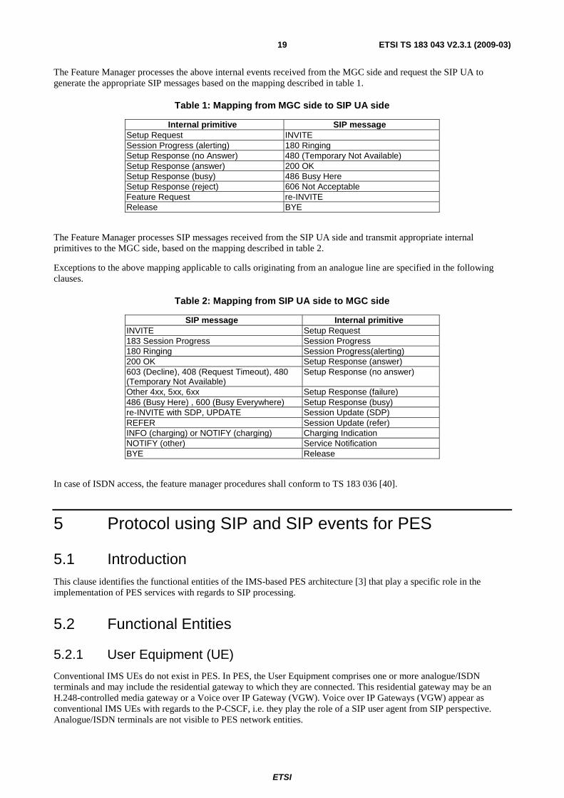
ETSI
ETSI TS 183 043 V2.3.1 (2009-03) 19
The Feature Manager processes the above internal events received from the MGC side and request the SIP UA to generate the appropriate SIP messages based on the mapping described in table 1.
Table 1: Mapping from MGC side to SIP UA side
Internal primitive SIP message Setup Request INVITE Session Progress (alerting) 180 Ringing Setup Response (no Answer) 480 (Temporary Not Available) Setup Response (answer) 200 OK Setup Response (busy) 486 Busy Here Setup Response (reject) 606 Not Acceptable Feature Request re-INVITE Release BYE
The Feature Manager processes SIP messages received from the SIP UA side and transmit appropriate internal primitives to the MGC side, based on the mapping described in table 2.
Exceptions to the above mapping applicable to calls originating from an analogue line are specified in the following clauses.
Table 2: Mapping from SIP UA side to MGC side
SIP message Internal primitive INVITE Setup Request 183 Session Progress Session Progress 180 Ringing Session Progress(alerting) 200 OK Setup Response (answer) 603 (Decline), 408 (Request Timeout), 480 (Temporary Not Available)
Setup Response (no answer)
Other 4xx, 5xx, 6xx Setup Response (failure) 486 (Busy Here) , 600 (Busy Everywhere) Setup Response (busy) re-INVITE with SDP, UPDATE Session Update (SDP) REFER Session Update (refer) INFO (charging) or NOTIFY (charging) Charging Indication NOTIFY (other) Service Notification BYE Release
In case of ISDN access, the feature manager procedures shall conform to TS 183 036 [40].
5 Protocol using SIP and SIP events for PES
5.1 Introduction This clause identifies the functional entities of the IMS-based PES architecture [3] that play a specific role in the implementation of PES services with regards to SIP processing.
5.2 Functional Entities
5.2.1 User Equipment (UE)
Conventional IMS UEs do not exist in PES. In PES, the User Equipment comprises one or more analogue/ISDN terminals and may include the residential gateway to which they are connected. This residential gateway may be an H.248-controlled media gateway or a Voice over IP Gateway (VGW). Voice over IP Gateways (VGW) appear as conventional IMS UEs with regards to the P-CSCF, i.e. they play the role of a SIP user agent from SIP perspective. Analogue/ISDN terminals are not visible to PES network entities.

ETSI
ETSI TS 183 043 V2.3.1 (2009-03) 20
NOTE: Analogue/ISDN terminals - "user equipment" - can also be connected to PES via an Access Gateway.
For the purpose of the PES, a residential VGW, in line with the behaviour of all VGWs, shall implement the role of a PES endpoint as described in clause 5.3.1.
5.2.2 Access Gateway Control Function (AGCF)
For the purpose of the PES, the AGCF shall implement the role of the PES access point as described in clause 5.3.2.
The AGCF is part of the trust domain.
The AGCF entity encompasses the functionality of an H.248 Media Gateway Controller (MGC) as defined in ITU-T Recommendation H.248.1 [22] and of a SIP User Agent as defined in RFC 3261 [38]. Within the AGCF, the MGC and SIP UA components are coordinated by a Feature Manager entity whose logical behaviour is described in annex B.
The AGCF shall appear to other CSCFs as if it were a P-CSCF.
5.2.3 Application Server (AS)
For the purpose of the PES, the AS shall implement the role of a PES application server, as described in clause 5.3.3.
NOTE: The PES architecture does not require that all application servers involved in sessions initiated/addressed by/to PES users adhere to the procedures prescribed for the PES application server role. Any application server that conforms to TS 182 006 [2] may be involved in such sessions.
5.2.4 Media Resource Function Controller (MRFC)
For the purpose of the PES, an MRFC shall implement the role of the PES announcement server as described in clause 5.3.4.
5.2.5 Media Gateway Controller Function (MGCF)
For the purpose of the PES, the MGCF shall implement the role of a PES interworking application as described in clause 5.3.5.
5.2.6 Interconnection Border Control Function (IBCF)
For the purpose of the PES, the IBCF shall implement the role of a PES Interconnection Application as described in clause 5.3.6.
5.2.7 Voice over IP gateway (VGW) acting as Access Gateway
For the purpose of the PES, an access VGW, in line with the behaviour of all VGWs, shall implement the role of the PES end point as described in clause 5.3.1.
The VGW entity encompasses the functionality of a Media Gateway Controller (MGC), Media Gateway (MG) and a SIP User Agent as defined in RFC 3261 [38]. Within the VGW, the MGC, MGW and SIP UA components are coordinated by a Feature Manager entity whose logical behaviour is described in annex B.
NOTE: The internal interfaces of the VGW are not standardized or testable.
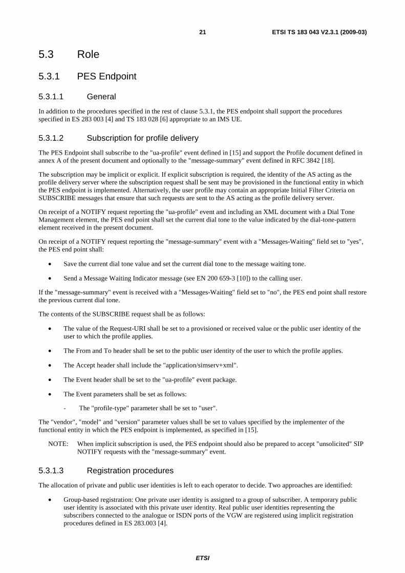
ETSI
ETSI TS 183 043 V2.3.1 (2009-03) 21
5.3 Role
5.3.1 PES Endpoint
5.3.1.1 General
In addition to the procedures specified in the rest of clause 5.3.1, the PES endpoint shall support the procedures specified in ES 283 003 [4] and TS 183 028 [6] appropriate to an IMS UE.
5.3.1.2 Subscription for profile delivery
The PES Endpoint shall subscribe to the "ua-profile" event defined in [15] and support the Profile document defined in annex A of the present document and optionally to the "message-summary" event defined in RFC 3842 [18].
The subscription may be implicit or explicit. If explicit subscription is required, the identity of the AS acting as the profile delivery server where the subscription request shall be sent may be provisioned in the functional entity in which the PES endpoint is implemented. Alternatively, the user profile may contain an appropriate Initial Filter Criteria on SUBSCRIBE messages that ensure that such requests are sent to the AS acting as the profile delivery server.
On receipt of a NOTIFY request reporting the "ua-profile" event and including an XML document with a Dial Tone Management element, the PES end point shall set the current dial tone to the value indicated by the dial-tone-pattern element received in the present document.
On receipt of a NOTIFY request reporting the "message-summary" event with a "Messages-Waiting" field set to "yes", the PES end point shall:
• Save the current dial tone value and set the current dial tone to the message waiting tone.
• Send a Message Waiting Indicator message (see EN 200 659-3 [10]) to the calling user.
If the "message-summary" event is received with a "Messages-Waiting" field set to "no", the PES end point shall restore the previous current dial tone.
The contents of the SUBSCRIBE request shall be as follows:
• The value of the Request-URI shall be set to a provisioned or received value or the public user identity of the user to which the profile applies.
• The From and To header shall be set to the public user identity of the user to which the profile applies.
• The Accept header shall include the "application/simserv+xml".
• The Event header shall be set to the "ua-profile" event package.
• The Event parameters shall be set as follows:
- The "profile-type" parameter shall be set to "user".
The "vendor", "model" and "version" parameter values shall be set to values specified by the implementer of the functional entity in which the PES endpoint is implemented, as specified in [15].
NOTE: When implicit subscription is used, the PES endpoint should also be prepared to accept "unsolicited" SIP NOTIFY requests with the "message-summary" event.
5.3.1.3 Registration procedures
The allocation of private and public user identities is left to each operator to decide. Two approaches are identified:
• Group-based registration: One private user identity is assigned to a group of subscriber. A temporary public user identity is associated with this private user identity. Real public user identities representing the subscribers connected to the analogue or ISDN ports of the VGW are registered using implicit registration procedures defined in ES 283.003 [4].

ETSI
ETSI TS 183 043 V2.3.1 (2009-03) 22
• Line-based registration: A private user identity and one more public user identities are associated with each analogue port/ISDN access connected to the VGW.
The two approaches are not mutually exclusive.
Depending on the registration method used, the To and From headers in the REGISTER request shall be set to a SIP URI that contains the temporary public user identity associated with the group to be registered or the public user identity associated with the subscriber to be registered.
NOTE: The temporary public user identity may be provisioned on the VGW or in case of line based registration may be built from the line or access identifier (e.g. [email protected]).
5.3.1.4 Charging procedures
A PES Endpoint supporting advice of charge services shall support the INFO method and shall accept MIME bodies of type "application/vnd.etsi.aoc+xml" (see annex E). An INFO request that transports a body with AOC information shall identify the payload as MIME type "application/vnd.etsi.aoc+xml", the MIME type associated with AOC information (see annex E), and shall identify in the "sv" or "schemaversion" parameter's value the versions of AOC XML Schema that can be used to validate the AOC information XML body (part). The versions - of the MIME type associated with AOC information (see clause 9.1) - indicated shall correspond with a value of the version attribute of the <schema> XML element of an AOC XML Schema (see annex E). If the "sv" or "schemaversion" parameter is absent, the PES Endpoint shall assume that version 1 of the XML Schema for the AOC information XML body is supported.
5.3.1.5 Outgoing Call
5.3.1.5.1 General
Calls initiated by a PES user via a PES end point shall operate following the UE call origination procedures defined in ES 283 003 [4].
5.3.1.5.2 Procedures for analogue lines
On receipt of a non-empty Setup-Request the PES Endpoint shall send an INVITE request with the call destination in the Request-URI, an SDP Offer for a voice call. The INVITE may include a P-Preferred-Identity header field set to the default identity associated with the analogue termination where the off-hook event was detected. If the P-Preferred-Identity is not sent then the PES Endpoint shall ensure that the From header contains the equivalent identity.
If line-based registration has been used this default identity is the first one received in the P-Associated-URI header.
If group-based registration has been used, this default identity is derived from the analogue termination identifier through a provisioned mapping table or by creating a URI from the analogue termination identifier (e.g. [email protected]). In the later case, it is assumed that the PES AS will replace the contents of the P-Asserted-Identity with a meaningful public user identity (i.e. a Directory number).
On receipt of an empty Setup-Request (i.e. without explicit destination information) the PES Endpoint shall build and send an INVITE Request as described above except that the Request-URI shall be set to a provisioned value (e.g. [email protected]). It is up to the PES Application Server to reject the call by sending back an appropriate response code or to substitute the Request-URI with a subscriber-specific default value before forwarding the INVITE requests towards a destination.
5.3.1.5.3 Procedures for ISDN access
The procedures specified TS 183 036 [40] apply.
If line-based registration is used, the PES Endpoint may set the P-Preferred-Identity header according to the calling party number received from the ISDN interface, as specified in TS 183 036 [40]. If the P-Preferred-Identity is not sent then the PES Endpoint shall ensure that the From header contains the equivalent identity. The PES Endpoint should verify that this identity is included in the P-Associated-URI header and otherwise overrides it with the first URI received in the P-Associated-URI.

ETSI
ETSI TS 183 043 V2.3.1 (2009-03) 23
If group-based registration is used the PES Endpoint should set the P-Preferred-Identity header to the default identity associated with the ISDN access where the call originates from. This default identity is derived from the ISDN access identifier through a provisioned mapping table or by creating a URI from the ISDN access identifier (e.g. [email protected]). In the later case, it is assumed that the PES AS will replace the contents of the P-Asserted-Identity with a meaningful public user identity (i.e. a Directory number).
NOTE: When the P-Preferred-Identity is set to an identity representing the ISDN access, the actual end user identity is still available in the From header as specified in TS 183 036 [40].
When performing interworking with the DSS.1 protocol, as specified in TS 183 036 [40], the PES end point shall indicate support of the application/vnd.etsi.pstn+xml MIME type.
5.3.1.5.4 Use of Overlap Signalling (Optional)
If Overlap Signalling is supported between the PES Endpoint and the originating PES Application Server the Overlap Signalling method used, either the Multiples INVITES method or the IN-Dialog method as described within annex F is dependent on national or network operator option. For ISDN Access the procedures specified in TS 183 036 [40] apply.
5.3.1.6 Terminating Call
5.3.1.6.1 General
Calls to a PES user via a PES end point shall operate following the UE call termination procedures defined in ES 283 003 [4].
5.3.1.6.2 Use of Overlap Signalling (Optional)
If Overlap Signalling is supported between the PES Endpoint and the terminating PES Application Server the Overlap Signalling method used, either the Multiples INVITES method or the IN-Dialog method as described within annex F is dependent on national or network operator option. For ISDN Access the procedures specified in TS 183 036 [40] apply.
5.3.1.7 Supplementary services configuration
5.3.1.7.1 Analogue lines
Analogue subscribers can control their supplementary services using service code commands as defined in ETS 300 738 [12] included in the user part of the Request-URI of an INVITE message. Further details are provided in annex C.
5.3.1.7.2 ISDN lines
ISDN subscribers can configure supplementary services using procedures applied at either the Gm reference point or the Ut reference point.
In the case of the Ut reference point, HTTP PUT, HTTP GET or HTTP DELETE requests are used in accordance with RFC 4825 [i.1] and the supplementary services application usage specified in TS 183 023 [33].
In case of the Gm reference point two procedures are available;
• Use of service code commands as for analogue subscribers, when ISDN stimulus procedures are used by the end user terminal.
• Use of the MESSAGE method when ISDN functional procedures are used by the end user terminal.
The MESSAGE method is used to convey the service related information to the relevant target. The information to configure a service is embedded in an XML instance document contained in the MESSAGE request as specified in TS 183 036 [40].
The P-Preferred-Identity shall be set as specified in clause 5.3.1.5 for an INVITE request.

ETSI
ETSI TS 183 043 V2.3.1 (2009-03) 24
The To and From headers shall be set to the public user identity associated to the supplementary service action.
When receiving a MESSAGE request conveying a response to an ISDN supplementary service interrogation procedure (see TS 183 036 [40]), the PES endpoint shall look for the In-Reply-To header field and evaluate its contents to identify the initial MESSAGE request to which it is responding.
5.3.2 PES Access Point
5.3.2.1 General
In addition to the procedures specified in the rest of clause 5.3.2, the behaviour of the PES access point shall be equivalent to the concatenation of the behaviour of a UE and a P-CSCF entity, as defined in ES 283.003 [4] and TS 183 028 [6].
NOTE: The above statement does not require AGCF implementations to execute UE and P-CSCF procedures in sequence.
5.3.2.2 Subscription for profile delivery
On receipt of a NOTIFY request reporting the "message-summary" event with a "Messages-Waiting" field set to "yes", the PES access point shall:
• Save the current dial tone value and set the current dial tone to the message waiting tone.
• Send a Message Waiting Indicator message (see EN 200 659-3 [10]) using the procedures described in clause 7.3.1.5.
Other procedures specified in clause 5.3.1.2 apply.
5.3.2.3 Registration Procedures
The following IMS parameters are assumed to available in a local data base:
• a private user identity;
• a public user identity; and
• a home network domain name to which SIP REGISTER requests are addressed.
The allocation of private and public user identities is left to each operator to decide. Two approaches are identified:
• Group-based registration: One private user identity is assigned to a group of subscribers. Groups should not contain subscribers connected to different gateways. A temporary public user identity is associated with this private user identity. Public user identities representing the subscribers connected to the analogue/ISDN ports controlled by the AGCF are registered using implicit registration procedures defined in ES 283.003 [4].
NOTE 1: The list of implicitly registered identities is provisioned on the UPSF and transmitted to the assigned S-CSCF during registration. This list may be in the form of one or more individual Tel URIs or SIP URIs with a user=phone qualifier and/or one or more wildcarded Public User Identities.
• Line-based registration: A private user identity and one or more public user identities are associated with each analogue port/ ISDN access connected to the MGWs controlled by the AGCF.
A combination of the two approaches may also be used.
The PES access point populates REGISTER messages as follows:
a) an Authorization header, with the username field, set to the value of the private user identity associated with the subscriber or subscriber group to be registered;
b) a From header set to the SIP URI that contains the temporary public user identity associated with the group to be registered or the public user identity associated with the subscriber to be registered;
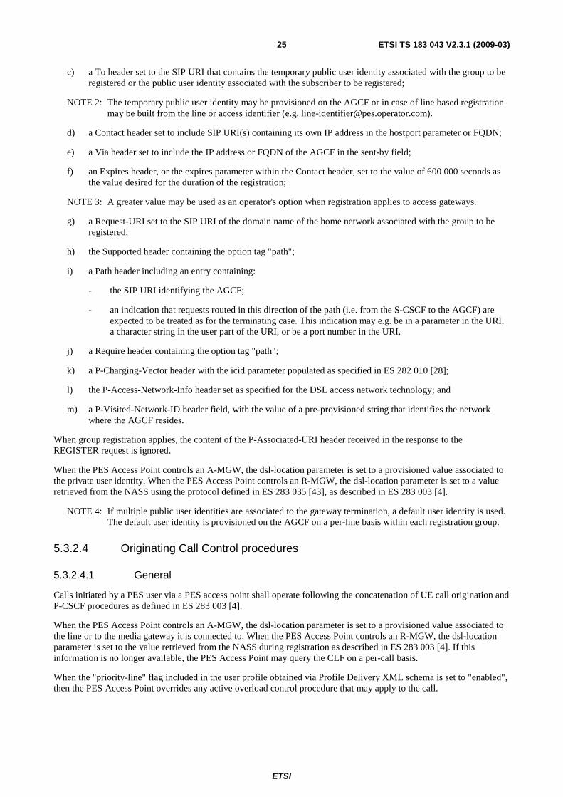
ETSI
ETSI TS 183 043 V2.3.1 (2009-03) 25
c) a To header set to the SIP URI that contains the temporary public user identity associated with the group to be registered or the public user identity associated with the subscriber to be registered;
NOTE 2: The temporary public user identity may be provisioned on the AGCF or in case of line based registration may be built from the line or access identifier (e.g. [email protected]).
d) a Contact header set to include SIP URI(s) containing its own IP address in the hostport parameter or FQDN;
e) a Via header set to include the IP address or FQDN of the AGCF in the sent-by field;
f) an Expires header, or the expires parameter within the Contact header, set to the value of 600 000 seconds as the value desired for the duration of the registration;
NOTE 3: A greater value may be used as an operator's option when registration applies to access gateways.
g) a Request-URI set to the SIP URI of the domain name of the home network associated with the group to be registered;
h) the Supported header containing the option tag "path";
i) a Path header including an entry containing:
- the SIP URI identifying the AGCF;
- an indication that requests routed in this direction of the path (i.e. from the S-CSCF to the AGCF) are expected to be treated as for the terminating case. This indication may e.g. be in a parameter in the URI, a character string in the user part of the URI, or be a port number in the URI.
j) a Require header containing the option tag "path";
k) a P-Charging-Vector header with the icid parameter populated as specified in ES 282 010 [28];
l) the P-Access-Network-Info header set as specified for the DSL access network technology; and
m) a P-Visited-Network-ID header field, with the value of a pre-provisioned string that identifies the network where the AGCF resides.
When group registration applies, the content of the P-Associated-URI header received in the response to the REGISTER request is ignored.
When the PES Access Point controls an A-MGW, the dsl-location parameter is set to a provisioned value associated to the private user identity. When the PES Access Point controls an R-MGW, the dsl-location parameter is set to a value retrieved from the NASS using the protocol defined in ES 283 035 [43], as described in ES 283 003 [4].
NOTE 4: If multiple public user identities are associated to the gateway termination, a default user identity is used. The default user identity is provisioned on the AGCF on a per-line basis within each registration group.
5.3.2.4 Originating Call Control procedures
5.3.2.4.1 General
Calls initiated by a PES user via a PES access point shall operate following the concatenation of UE call origination and P-CSCF procedures as defined in ES 283 003 [4].
When the PES Access Point controls an A-MGW, the dsl-location parameter is set to a provisioned value associated to the line or to the media gateway it is connected to. When the PES Access Point controls an R-MGW, the dsl-location parameter is set to the value retrieved from the NASS during registration as described in ES 283 003 [4]. If this information is no longer available, the PES Access Point may query the CLF on a per-call basis.
When the "priority-line" flag included in the user profile obtained via Profile Delivery XML schema is set to "enabled", then the PES Access Point overrides any active overload control procedure that may apply to the call.

ETSI
ETSI TS 183 043 V2.3.1 (2009-03) 26
5.3.2.4.2 Procedures for analogue lines
On receipt of a non-empty Setup-Request the PES access point shall send an INVITE request with the call destination in the Request-URI, an SDP Offer set according to the information received from the MGF and a P-Asserted-Identity header field set according to the default identity associated with the analogue termination where the off-hook event was detected.
If line-based registration has been used this default identity is the first one received in the P-Associated-URI header.
If group-based registration has been used, this default identity is derived from the analogue termination identifier through a provisioned mapping table or by creating a URI from the analogue termination identifier (e.g. [email protected]). In the later case, it is assumed that the PES AS will replace the contents of the P-Asserted-Identity with a meaningful public user identity (i.e. a Directory number).
On receipt of an empty Setup-Request (i.e. without explicit destination information) the PES access point shall build and send an INVITE Request as described above except that the Request-URI shall be set to a provisioned value (e.g. [email protected]). It is up to the PES Application Server to reject the call by sending back an appropriate response code or to substitute the Request-URI with a subscriber-specific default value before forwarding the INVITE requests towards a destination.
5.3.2.4.3 Procedures for ISDN access
The procedures specified TS 183 036 [40] apply.
If line-based registration is used, the PES Access Point shall set the P-Asserted-Identity header according to the calling party number received from the ISDN interface, as specified in TS 183 036 [40]. The PES Endpoint should verify that this identity is included in the P-Associated-URI header and otherwise overrides it with the first URI received in the P-Associated-URI.
If group-based registration is used the PES Access Point should set the P-Asserted-Identity header to the default identity associated with the ISDN access where the call originates from. This default identity is derived from the ISDN access identifier through a provisioned mapping table or by creating a URI from the ISDN access identifier (e.g. [email protected]). In the later case, it is assumed that the PES AS will replace the contents of the P-Asserted-Identity with a meaningful public user identity (i.e. a Directory number).
When performing interworking with the DSS.1 protocol, as specified in TS 183 036 [40], the PES access point shall indicate support of the application/vnd.etsi.pstn+xml MIME type.
5.3.2.4.4 Use of Overlap Signalling (Optional)
If Overlap Signalling is supported between the PES Endpoint and the originating PES Application Server the Overlap Signalling method used, either the Multiples INVITES method or the IN-Dialog method as described within annex F is dependent on national or network operator option. For ISDN Access the procedures specified in TS 183 036 [40] apply.
5.3.2.5 Terminating Call Control procedures
5.3.2.5.1 General
Terminating calls received by a PES access point shall operate following the UE call termination procedures defined in ES 283 003 [4]. The P-Called-Party header value is used to fetch the termination to which the call shall be delivered.
When the PES Access Point controls an A-MGW, the dsl-location parameter is set to a provisioned value associated to the line or to the media gateway it is connected to. When the PES Access Point controls an R-MGW, the dsl-location parameter is set to the value retrieved from the NASS during registration as described in ES 283 003 [4]. If this information is no longer available, the PES Access Point may query the CLF on a per-call basis.
When performing interworking with the DSS.1 protocol, as specified in TS 183 036 [40], the PES access point shall indicate support of the application/vnd.etsi.pstn+xml MIME type.
When the "priority-line" flag included in the user profile obtained via Profile delivery XML schema is set to "enabled", then the PES Access Point overrides any active overload control procedure that may apply to the call.

ETSI
ETSI TS 183 043 V2.3.1 (2009-03) 27
5.3.2.5.2 Use of Overlap Signalling (Optional)
If Overlap Signalling is supported between the PES Access Point and the terminating PES Application Server the Overlap Signalling method used, either the Multiples INVITES method or the IN-Dialog method as described within annex F is dependent on national or network operator option. For ISDN Access the procedures specified in TS 183 036 [40] apply.
5.3.2.6 Charging procedures
A PES access point supporting advice of charge services shall support the INFO method and shall accept MIME bodies of type "application/vnd.etsi.aoc+xml". An INFO request that transports a body with AOC information shall identify the payload as MIME type "application/vnd.etsi.aoc+xml"", the MIME type associated with AOC information (see annex E), and shall identify in the "sv" or "schemaversion" parameter's value the versions of AOC XML Schema that can be used to validate the AOC information XML body (part). The versions - of the MIME type associated with AOC information (see annex E) - indicated shall correspond with a value of the version attribute of the <schema> XML element of an AOC XML Schema (see e.g. annex E). If the "sv" or "schemaversion" parameter is absent, the PES access point shall assume that version 1 of the XML Schema for the AOC information XML body is supported.
5.3.2.7 Supplementary services configuration
5.3.2.7.1 Analogue lines
Analogue subscribers can control their supplementary services using service code commands as defined in ETS 300 738 [12] included in the user part of the Request-URI of an INVITE message. Further details are provided in annex C.
5.3.2.7.2 ISDN lines
ISDN subscribers can configure supplementary services using procedures applied at either the Gm reference point or the Ut reference point.
In the case of the Ut reference point, HTTP PUT, HTTP GET or HTTP DELETE requests are used in accordance with RFC 4825 [i.1] and the supplementary services application usage specified in TS 183 023 [33].
In case of the Gm reference point two procedures are available:
• Use of service code commands as for analogue subscribers, when ISDN stimulus procedures are used by the end user terminal.
• Use of the MESSAGE method when ISDN functional procedures are used by the end user terminal.
The MESSAGE method is used to convey the service related information to the relevant target. The information to configure a service is embedded in an XML instance document contained in the MESSAGE request as specified in TS 183 036 [40].
The P-Asserted-Identity shall be set as specified in clause 5.3.1.5 for an INVITE request.
The To and From headers shall be set to the public user identity associated to the supplementary service action.
When receiving a MESSAGE request conveying a response to an ISDN supplementary service interrogation procedure (see TS 183 036 [40]), the PES endpoint shall look for the In-Reply-To header field and evaluate its contents to identify the initial MESSAGE request to which it is responding.
5.3.3 PES Application Server
5.3.3.1 General
In addition to the procedures specified in the rest of clause 5.3.3, the PES application server shall support the procedures specified in ES 283 003 [4] appropriate to an application server.

ETSI
ETSI TS 183 043 V2.3.1 (2009-03) 28
5.3.3.2 Basic call procedures
A PES application server can act either as a proxy server or as a Back to Back User Agent (B2BUA) while processing calls. When acting as a B2BUA, the PES application server provides both originating UA and terminating UA functions as described in ES 283 003 [4]. As an originating UA that sends outbound INVITE requests, the PES application server must appropriately handle responses received from a forking proxy and must appropriately interwork provisional and final INVITE responses, as well as other SIP requests, between the originating UA and terminating UA functions employed on a single call.
When handling an outgoing call, the PES application server shall populate the "cpc" URI parameter in the contents of the P-Asserted-Identity header as defined in ES 283 003 [4] in each INVITE request, unless the parameter value is "ordinary". How the PES application server determines the value of this parameter (UPSF query, local configuration data, etc.) is outside the scope of the present document.
When handling an outgoing call, the PES application server shall override the P-Asserted-Identity with a meaningful public user identity (i.e. a Directory number) in each INVITE request if the received P-Asserted-Identity is in the form or an analogue line or ISDN access identifier or represents a gateway. How the PES application server determines the meaningful identity (UPSF query, local configuration data, from header contents, etc.) is outside the scope of the present document.
When handling an incoming call, the PES application server may rewrite the Request-URI with an identity derived from the line/access if group registration was used. In this case, the PES application server shall include an original dialog identifier in the top most route header of the INVITE request sent to the S-CSCF.
5.3.3.3 Announcement procedures
The PES application server shall have the capability of requesting announcements during any phase of a session, according to the procedures described in TS 183 028 [6].
The PES application server shall use the ANNC URL syntax defined in [16] when requesting a PES announcement server to play an announcement.
A PES application server acting as a B2BUA must appropriately handle received Call-Info, Alert-Info, and Error-Info headers that contain requests to play announcements, as defined in TS 183 028 [6]. Depending on the application, this may mean relaying the header toward the originating PES endpoint or PES access point, connecting the originating UE to an MRF, or ignoring the announcement request and providing some other call processing (such as with a simultaneous ringing application that ignores failure announcements from unsuccessful call legs).
When sending announcements during the call setup phase, the PES application server shall include a P-Early-Media header set according to TS 183 028 [6].
5.3.3.4 Profile Delivery
The PES application server shall act as a profile delivery server and manage Profile documents whose structure conforms to the XML schema defined in annex A and TS 183 023 [33].
The contents of the NOTIFY request shall be as follows:
• The Event header shall be set to the "ua-profile" event package.
• The "effective-by" parameter for the event header shall be set to 0.
• The content type shall be set to "application/simserv+xml".
In case of implicit subscription the first NOTIFY message is sent when the current profile differs from the network's default profile.
Changes to these documents shall be notified by reporting the "ua-profile" event defined in [15]. How the PES server keeps track of changes to these documents is outside the scope of the present document.
ETSI
ETSI TS 183 043 V2.3.1 (2009-03) 29
5.3.3.5 Transport of ISUP information
5.3.3.5.1 General
Clause 5.3.3.5 describes the general behaviour of the PES application server in the case the PES application server is capable of exchanging ISUP information, as defined in ITU-T Recommendation Q.763 [29], carried within Narrowband Signalling Syntax (NSS) [31] message bodies with its SIP signalling peers to perform service related signalling that is capable of interworking with PSTN services. Clause C.1.4 lists examples of services some of which may require the use of encapsulated ISUP information. The sending or receiving of ISUP information in NSS message bodies is applicable to any of the following roles of the Application Server:
• PES application server acting as terminating UA or redirect server.
• PES application server acting as originating UA.
• PES application server performing 3rd party call control.
The procedures defined in the following clauses allow a PES application server to discover whether or not its peer SIP signalling entity (i.e. the next UA along the signalling path, which may be a B2BUA, and therefore excluding any intermediate proxies) is capable of supporting NSS message bodies within SIP messages, and to successfully support the additional exchange of ISUP information needed for those services supported in common by endpoints supporting potentially different sets of services. Each IMS PES must assure that NSS message bodies are not forwarded to UEs and are not forwarded to untrusted SIP networks according to local policy. Clause 5.3.3.5.2.4 describes the role of the PES application server in maintaining NSS security.
NOTE: Services that require manipulation of the ISUP information within NSS message bodies cannot be implemented on application servers acting as a SIP proxy.
The PES application server shall support parameter translations and defaults defined in ES 283 027 [32] for the ISUP information needed for supported services. The PES application server shall also send each piece of ISUP information in the appropriate SIP message so as to allow the valid interworking with the corresponding PSTN services according to ES 283 027 [32]. The PES application server shall not include in NSS message bodies any ISUP information that is already represented by SIP signalling.
The handling of forked requests with NSS message bodies is for further study.
5.3.3.5.2 Sending NSS message bodies to a peer SIP signalling entity
5.3.3.5.2.1 General
The PES application server shall send an NSS message body with encapsulated ISUP information in the appropriate SIP message to a peer SIP signalling entity according to the clauses 5.3.3.5.2.2 through 5.3.3.5.2.7, when all the following conditions are satisfied.
• The PES application server is capable of performing service related signalling using ISUP information for one or more of the services it supports.
• An event associated with one of the supported services occurs that requires that ISUP information be sent to the peer SIP signalling entity. This event may be the receipt of signalling information from another SIP interface to the PES application server, or a service event internal to the PES application server.
• Either the encapsulating message is the initial INVITE request, or the peer SIP signalling entity has previously indicated support for NSS message bodies within the associated dialog (see clause 5.3.3.5.2.2).
• The SIP signalling in the encapsulating message cannot represent the information, and the information is different from the default values defined in ES 283 027 [32].
NOTE: Information may be duplicated in the NSS and vnd.etsi.pstn XML MIME bodies.

ETSI
ETSI TS 183 043 V2.3.1 (2009-03) 30
5.3.3.5.2.2 Determining support for NSS message bodies
When constructing an initial INVITE request, an originating PES application server that supports any services that require encapsulated ISUP information shall include an indication of support for NSS by including an Accept header in the initial INVITE request that indicates support for NSS ("application/nss") according to clause 5.3.3.5.2.3. Until the originating PES application server receives an indication of support for NSS message bodies from its peer SIP signalling entity (by receipt of a SIP message that either includes an Accept header indicating support for NSS or an NSS message body), the originating PES application server shall not send any further NSS message bodies within the dialog.
If a terminating PES application server receives an initial INVITE request that does not include an Accept header indicating support for NSS, the terminating PES application server shall not send NSS message bodies within the dialog. If a terminating PES application server supporting any services that require the signalling of ISUP information receives an initial INVITE request that includes an Accept header indicating support for NSS, the terminating PES application server shall indicate support of NSS in the first SIP message to its SIP signalling peer. The terminating PES application server indicates support of NSS using the Accept header if allowed in the SIP message. Otherwise, the terminating PES application server does this by including an NSS message body in the SIP message. In the later case, if there is no need to send ISUP information to the SIP signalling peer in the first SIP message, the terminating PES application server shall send a generic parameter list (GPL) NSS message with no parameters.
A terminating PES application server not supporting NSS will follow procedures in clause 5.3.3.5.3.1.
5.3.3.5.2.3 NSS message bodies
The PES application server shall format the NSS message body according to ITU-T Recommendation Q.1980.1 [31]. The Content-Type header field associated with the NSS message body shall be included as follows:
• Content-Type: application/nss.
The Content-Disposition header field associated with the NSS message body shall be set in one of the following two ways (see clause 5.3.3.5.2.7):
• Content-Disposition: signal; handling = required; or
• Content-Disposition: signal; handling = optional.
5.3.3.5.2.4 ISUP information security
If network entities in the IMS PES cannot be relied on to provide ISUP information confidentiality and integrity, then the PES application server shall not send NSS message bodies or process received NSS message bodies (other than ignoring or rejecting any NSS message bodies).
A PES application server acting as routeing B2BUA shall remove NSS message bodies and indications of NSS support (e.g. an NSS entry in the Accept header) from SIP messages being forwarded towards each UE. If a PES application server is assigned to remove the NSS message bodies from SIP messages being forwarded to a UE, then the PES application server shall be configured within the terminating filter criteria for its UE.
5.3.3.5.2.5 Determining in which message to encapsulate ISUP information
If a service logic event coincides with one of the SIP basic call control messages, i.e. INVITE request, re-INVITE request, BYE request, UPDATE request, or responses to these messages, any required ISUP information shall be encapsulated in the corresponding SIP message.
If a service logic event requiring the sending of ISUP information occurs that does not coincide with one of the SIP basic call control messages, the PES application server shall send the ISUP information encapsulated in an INFO request or a 183 (Session Progress) response, as described below.
An originating PES application server cannot send an INFO request until it receives a reliable provisional response or final response.

ETSI
ETSI TS 183 043 V2.3.1 (2009-03) 31
A terminating PES application server cannot send an INFO request until a reliable provisional response or final response has been sent by the PES application server and the response has been acknowledged. If service logic requires an NSS message body marked with optional handling (see clause 5.3.3.5.2.7) to be sent before an INFO request can be sent, the terminating PES application server may send the NSS message body in a 183 (Session Progress) reliable response. If the service logic requires an NSS message body marked with required handling to be sent before an INFO request can be sent, the terminating PES application server shall first send a 183 (Session Progress) reliable response without an NSS message body and wait for acknowledgment of the response before sending the NSS message body in the INFO request.
5.3.3.5.2.6 Determining the NSS message identifier code
If the ISUP information included in the NSS message body uniquely identifies the ISUP message needed to interwork the ISUP information to an ISUP interface, or if the interworking with ISUP is unambiguously identified by the SIP signalling and/or the encapsulated ISUP information, the PES application server shall include the ISUP information in an NSS GPL message. Otherwise, the PES application server shall include an explicit ISUP message name in the NSS message body.
5.3.3.5.2.7 Determining the content disposition handling
5.3.3.5.2.7.1 Content disposition for the initial INVITE request
A PES application server sending an INVITE request with an NSS message body shall mark it for required handling (see clause 5.3.3.5.2.3) if the service logic requires the peer SIP signalling entity to understand the ISUP information.
Otherwise, the PES application server shall mark the NSS message body in the initial INVITE request for optional handling.
If the peer SIP signalling entity is unable to process an NSS message body marked for required handling in an initial INVITE request, it will reject the INVITE request with a failure response, allowing the originating PES application server, or perhaps a proxy on the path, to optionally retry the request to an alternate destination that may be capable of handling the NSS message body.
5.3.3.5.2.7.2 Content disposition for the INFO request
A PES application server sending an INFO request with an NSS message body shall mark it for required handling if the service logic requires the peer SIP signalling entity to understand the ISUP information.
Otherwise, the PES application server shall mark the NSS message body in the INFO request for optional handling.
If the peer SIP signalling entity rejects an NSS message body in an INFO request by returning a failure response, the PES application server performs the service procedure that applies when unable to signal ISUP information, if such a procedure exists, and continues the call associated with the parent dialog. The PES application server shall release the call if the INFO request fails and there is any ISUP information in the INFO request that requires call release if it cannot be processed or forwarded.
5.3.3.5.2.7.3 Content disposition for other SIP messages
If the previous clauses do not apply, the PES application server shall mark the NSS message body in the SIP message for optional handling.
NOTE: A PES application server sending an NSS message body in any SIP response message will mark it for optional handling, since the peer SIP signalling entity cannot reject the message.
5.3.3.5.3 Receiving an NSS message body from a peer SIP signalling entity
5.3.3.5.3.1 General
On receipt of a SIP message containing an NSS message body, a PES application server supporting services that require encapsulated ISUP information shall de-encapsulate the ISUP information from the NSS message body, perform the processing described in the clause 5.3.3.5.3.2, and trigger the relevant service logic.

ETSI
ETSI TS 183 043 V2.3.1 (2009-03) 32
If the PES application server does not receive ISUP information required by the service logic, the service logic defines the PES application server behaviour, e.g. by assuming default values defined by the service logic.
5.3.3.5.3.2 ISUP compatibility procedures
A PES application server shall reject with a SIP 603 (Decline) response a SIP request that includes an NSS message body that is marked for required handling, that includes ISUP information that the PES application server does not support, and that either includes no compatibility parameter for the unsupported information, or includes a compatibility parameter for the unsupported information that requires release when the parameter is unsupported. Otherwise, the PES application server shall ignore any unsupported ISUP information.
The PES application server may ignore any unsupported ISUP information it receives in an NSS message body marked for optional handling or perform any other behaviour determined by the service logic.
5.3.3.6 Handling of charging information
When processing originating sessions, the PES application server shall be able to act as a Charging Generation Point (CGP) and send the appropriate charging information to the PES access point/endpoint. The PES application server shall accept charging information in the format defined in TS 183 058 [42], annex C and may accept charging information received as part of an NSS body (see clause 5.3.3.5).
When processing originating sessions, the PES application server shall be able to insert advice of charge information in SIP messages sent in the upstream direction, using the mechanism described in TS 183 047 [7].
When processing terminating sessions, the PES application server may be able to act as a Charging Determination Point (CGP) and send charging information upstream using the format defined in TS 183 058 [42], annex C.
5.3.3.7 Supplementary services configuration
Three modes of operation may be supported depending on the type access and the operator's policy:
• Service code commands received in the Request-URI of INVITE message at the ISC reference point.
• XML documents received in HTTP PUT, HTTP GET or HTTP DELETE requests received at the Ut reference point in accordance with RFC 4825 [i.1] and the supplementary services application usage specified in TS 183 023 [33].
• XML documents received in MESSAGE messages as specified in TS 183 036 [40].
When sending a MESSAGE request is response to another MESSAGE request, the PES AS shall set the In-Reply-To header field value to the value of the Call-ID header field received in the incoming request.
5.3.4 PES Announcement Server
5.3.4.1 General
In addition to the procedures specified in the rest of clause 5.3.4, the PES announcement server shall support the procedures specified in ES 283 003 [4] appropriate to an MRFC.
5.3.4.2 Announcement procedures
The PES announcement server shall support the ANNC URL syntax defined in [16] when providing announcements, prompt and collect functions, and multi-party conferencing.
5.3.5 PES Interworking Application
5.3.5.1 General
In addition to the procedures specified in the rest of clause 5.3.5, the PES interworking application shall support the procedures specified in ES 283 003 [4] and TS 183 028 [6] appropriate to an MGCF.
ETSI
ETSI TS 183 043 V2.3.1 (2009-03) 33
The PES interworking application shall support the P-Early-Media header.
5.3.5.2 Routing procedures
In case of incoming calls from legacy networks, the PES interworking application determines the next hop in IP routing depending on received signalling information, based on configuration data and/or data base look up. The next hop may be an I-CSCF, a BGCF or an IBCF.
Based on the destination and local policy rules, the PES interworking application may include ISUP information in the messages sent to the next entity, as described in clause 5.3.5.4.
5.3.5.3 Handling of charging information
The PES interworking application shall be able to insert charging information in SIP messages sent in the upstream direction, based on charging information received from the PSTN. The PES interworking application shall use the format defined in TS 183 058 [42], annex C.
5.3.5.4 Transport of ISUP information
5.3.5.4.1 General
The procedures in the clause 5.3.5.4 allow the PES interworking application to discover whether or not its peer SIP signalling entity is capable of supporting the encapsulation of ISUP information in Narrowband Signalling Syntax (NSS) [31] message bodies within SIP messages, and to successfully support the additional exchange of ISUP information needed for those services supported in common by endpoints supporting potentially different sets of services. These procedures are based on ES 283 027 [32] with the extended capabilities described in the present document. When signalling ISUP information within a SIP dialog, the PES interworking application shall act as either a Type A or Type B exchange depending on the role (e.g. gateway between operators, transit) the PES interworking application is performing for that particular call and the ability to exchange ISUP information during the call. Clause C.1.4 lists examples of services some of them may require the use of encapsulated ISUP information. Each IMS PES must assure that ISUP information is not shared with UEs and untrusted SIP networks according to local policy. Clause 5.3.5.4.2.4 describes the PES interworking application's role in maintaining NSS security.
The PES interworking application shall support parameter translations and defaults defined in ES 283 027 [32] for the ISUP information needed for supported services. The PES interworking application shall also send each piece of ISUP information in the appropriate SIP message so as to allow valid interworking with the corresponding PSTN services according to ES 283 027 [32]. The PES interworking application shall not include in NSS message bodies any ISUP information that is already represented by SIP signalling.
The handling of forked requests with NSS message bodies is for further study.
5.3.5.4.2 Sending ISUP information to a peer SIP signalling entity
5.3.5.4.2.1 General
The PES interworking application shall send an NSS message body with encapsulated ISUP information in the appropriate SIP message to a peer SIP signalling entity according to the clauses 5.3.5.4.2.2 through 5.3.5.4.2.7, when all the following conditions are satisfied.
• Either the encapsulating message is the initial INVITE request, or the peer SIP signalling entity has previously indicated support for NSS message bodies within the associated dialog (see clause 5.3.5.4.2.2).
• An event occurs requiring signalling to the peer SIP signalling entity. This event may be the receipt of an ISUP message from the PSTN, or an event internal to the MGCF.
• According to local configuration, selected ISUP information shall be encapsulated and sent towards the peer SIP signalling entity.
• The SIP signalling in the encapsulating message cannot represent the information, and the information is different from the default values defined in ES 283 027 [32].

ETSI
ETSI TS 183 043 V2.3.1 (2009-03) 34
NOTE: Information may be duplicated in the NSS and vnd.etsi.pstn XML MIME bodies.
5.3.5.4.2.2 Determining support for NSS message bodies
When constructing an initial INVITE request, the O-MGCF supporting NSS message bodies shall include an indication of support for NSS by including an Accept header in the initial INVITE request that indicates support for NSS ("application/nss") according to clause 5.3.5.4.2.3. Until the O-MGCF receives an indication of support for NSS message bodies from its peer SIP signalling entity (by receipt of a SIP message that either includes an Accept header indicating support for NSS or an NSS message body), the O-MGCF shall not send any further NSS message bodies within the dialog.
If an I-MGCF receives an initial INVITE request that does not include an Accept header indicating support for NSS, the I-MGCF shall not send NSS message bodies within the dialog. If an I-MGCF supporting NSS receives an initial INVITE request that includes an Accept header indicating support for NSS, the I-MGCF shall indicate support of NSS in the first SIP message to its SIP signalling peer. The I-MGCF indicates support of NSS using the Accept header if allowed in the SIP message. Otherwise, the I-MGCF does this by including an NSS message body in the SIP message. In the later case, if there is no need to send ISUP information to the SIP signalling peer in the first SIP message, the I-MGCF shall send a generic parameter list (GPL) NSS message with no parameters.
5.3.5.4.2.3 NSS message bodies
The PES interworking application shall format the NSS message body according to ITU-T Recommendation Q.1980.1 [31]. The Content-Type header field associated with the NSS message body shall be included as follows:
• Content-Type: application/nss.
The Content-Disposition header field associated with the NSS message body shall be set in one of the following two ways (see clause 5.3.5.4.2.7):
• Content-Disposition: signal; handling = required; or
• Content-Disposition: signal; handling = optional.
5.3.5.4.2.4 ISUP information security
If network entities in the IMS PES cannot be relied on to provide NSS confidentiality and integrity, then the PES interworking application shall not send NSS message bodies or process received NSS message bodies (other than ignoring or rejecting any NSS message bodies).
5.3.5.4.2.5 Determining in which SIP message to encapsulate ISUP information
If an event requiring the sending of ISUP information coincides with one of the SIP basic call control messages, i.e. INVITE request, re-INVITE request, BYE request, UPDATE request, or responses to these messages, any required ISUP information shall be encapsulated in the corresponding SIP message.
If an event requiring the sending of ISUP information occurs that does not coincide with one of the SIP basic call control messages, the AS shall send the ISUP information encapsulated in an INFO request or a 183 (Session Progress) response, as described below. Clause 5.3.5.4.4 describes events unrelated to SIP basic call control messages that may require the sending of ISUP information.
An O-MGCF cannot send an INFO request until it receives a reliable provisional response or final response.
An I-MGCF cannot send an INFO request until a reliable provisional response or final response has been sent by the I-MGCF and the response has been acknowledged. If an event requires an NSS message body marked with optional handling (see clause 5.3.5.4.2.7) to be sent before an INFO request can be sent, the I-MGCF may send the NSS message body in a 183 (Session Progress) reliable response. If an event requires an NSS message body marked with required handling to be sent before an INFO request can be sent, the I-MGCF shall first send a 183 (Session Progress) reliable response without an NSS message body and wait for acknowledgment of the response before sending the NSS message body in the INFO request.
ETSI
ETSI TS 183 043 V2.3.1 (2009-03) 35
5.3.5.4.2.6 Determining the NSS message identifier code
If the ISUP information included in the NSS message body uniquely identify the ISUP message needed to interwork the ISUP information to an ISUP interface, or if the interworking with ISUP is unambiguously identified by the SIP signalling and/or the encapsulated ISUP information, the PES interworking application shall include the ISUP information in an NSS GPL message. Otherwise, the PES interworking application shall include an explicit ISUP message name in the NSS message body.
5.3.5.4.2.7 Determining the content disposition handling
5.3.5.4.2.7.1 Content disposition for the initial INVITE request
An O-MGCF sending an initial INVITE request with an NSS message body shall mark it for required handling (see clause 5.3.5.4.2.3) in any of the following cases:
• The ISUP preference indicator received from the PSTN is set to "ISUP required all the way".
• The parameter compatibility parameter associated with any ISUP parameter in the NSS message body indicates "release call" or "discard message" when pass on is not possible.
• As a matter of local policy.
Otherwise, the O-MGCF shall mark the NSS message body in the initial INVITE request for optional handling.
If the peer SIP signalling entity is unable to process an NSS message body marked for required handling in an initial INVITE request, it will reject the INVITE request with a failure response, allowing the O-MGCF, or perhaps a proxy on the path, to optionally retry the request to an alternate destination that may be capable of handling the NSS message body.
5.3.5.4.2.7.2 Content disposition for the INFO request
If an event occurs requiring the sending of an NSS message body, the event does not coincide with one of the SIP basic call control messages (see table 1 in clause 5.3.5.4.4.1), and any failure procedures are defined when unable to pass on ISUP information in the NSS message body to the peer SIP signalling entity, the PES interworking application shall mark the NSS for required handling. For example, the "Interactions with other networks" clause of each relevant supplementary service specification (see table C.1) specifies the PES interworking application procedures when unable to pass on ISUP information. Otherwise, the PES interworking application shall mark the NSS message body for optional handling.
Otherwise, the O-MGCF shall mark the NSS message body in the INFO request for optional handling.
If the peer SIP signalling entity rejects an NSS message body in an INFO request by returning a failure response, the PES interworking application performs the service procedure for failing to pass on the ISUP information, if such a procedure exists, and continues the call associated with the parent dialog. The PES interworking application shall release the call if the INFO request fails and there is any ISUP information in the INFO request that requires call release if it cannot be processed or forwarded.
5.3.5.4.2.7.3 Content disposition for other SIP messages
A PES interworking application sending an NSS message body in any SIP message other than the INVITE request and the INFO request shall mark it for optional handling.
NOTE: A PES interworking application sending an NSS message body in any SIP response message will mark it for optional handling, since the peer SIP signalling entity cannot reject the message.
5.3.5.4.3 Receiving an NSS message body from a peer SIP signalling entity
5.3.5.4.3.1 General
On receipt of a SIP message containing an NSS message body, the PES interworking application supporting NSS shall de-encapsulate the ISUP information from the NSS message body, perform the processing described in clauses 5.3.5.4.3.2 and 5.3.5.4.3.3, and pass the ISUP information to the relevant ISUP procedures.

ETSI
ETSI TS 183 043 V2.3.1 (2009-03) 36
5.3.5.4.3.2 ISUP compatibility procedures (local policy options)
A PES interworking application shall reject with a SIP 603 (Decline) response a SIP request that includes an NSS message body that is marked for required handling, that includes ISUP information that the PES interworking application does not support, and that requires release according to ISUP procedures when unsupported. Otherwise, the PES interworking application shall ignore any unsupported ISUP information.
The PES interworking application may ignore any unsupported ISUP information it receives in an NSS message body marked for optional handling or perform any other behaviour determined by the ISUP procedures.
5.3.5.4.3.3 Alignment of SIP signalling and NSS message body contents
On receipt of a SIP message containing an NSS message body, the PES interworking application shall use the encapsulated ISUP information in preference to any value determined by interworking procedures and default values defined in ES 283 027 [32].
5.3.5.4.4 ISUP messages for special consideration
5.3.5.4.4.1 General
Table 3 lists the PES interworking application behaviour upon receipt of ISUP messages that have no counterparts in basic SIP call control messages.
Table 3: ISUP messages for special consideration
ISUP message Reference Subsequent address message 5.3.5.4.4.6 Reset circuit 5.3.5.4.4.2 Call progress 5.3.5.4.4.3 (see note 1) Circuit group blocking 5.3.5.4.4.2 Circuit group blocking acknowledgement 5.3.5.4.4.2 Circuit group query (national use) 5.3.5.4.4.2 Circuit group query response (national use) 5.3.5.4.4.2 Group reset 5.3.5.4.4.2 Circuit group reset acknowledgement 5.3.5.4.4.2 Confusion 5.3.5.4.4.2 or 5.3.5.4.4.3 (see note 2) Facility reject 5.3.5.4.4.2 or 5.3.5.4.4.3 (see note 2) User-to-user information 5.3.5.4.4.3 Forward transfer 5.3.5.4.4.3 Subsequent directory number (national use) 5.3.5.4.4.3 Suspend 5.3.5.4.4.3 or 5.3.5.4.4.5 Resume 5.3.5.4.4.3 or 5.3.5.4.4.5 Blocking 5.3.5.4.4.2 Blocking acknowledgement 5.3.5.4.4.2 Continuity check request 5.3.5.4.4.2 Continuity 5.3.5.4.4.2 Unblocking 5.3.5.4.4.2 Unblocking acknowledgement 5.3.5.4.4.2 Unequipped CIC (national use) 5.3.5.4.4.2 Circuit group unblocking 5.3.5.4.4.2 Circuit group unblocking acknowledgement 5.3.5.4.4.2 Charging information (national use) 5.3.5.4.4.3 Facility accepted 5.3.5.4.4.3 Facility request 5.3.5.4.4.3 User part test 5.3.5.4.4.2 User part available 5.3.5.4.4.2 Facility 5.3.5.4.4.3 Network resource management 5.3.5.4.4.3 Identification request 5.3.5.4.4.3 Identification response 5.3.5.4.4.3 Information (national use) 5.3.5.4.4.3 Information request (national use) 5.3.5.4.4.3 Segmentation 5.3.5.4.4.4 Loop back acknowledgment (national use) 5.3.5.4.4.3
ETSI
ETSI TS 183 043 V2.3.1 (2009-03) 37
ISUP message Reference Loop prevention 5.3.5.4.4.3 Overload (national use) 5.3.5.4.4.2 Pass-along (national use) 5.3.5.4.4.3 Application transport 5.3.5.4.4.2 or 5.3.5.4.4.3 (see note 2) Pre-release information 5.3.5.4.4.3 Release complete 5.3.5.4.4.2 NOTE 1: This is the default handling of the ISUP information associated with the Call
Progress (CPG) message when other clauses in the present document do not apply. The ISUP information associated with a CPG message may be encapsulated in an 18X response, an UPDATE request, a reINVITE request, or an INFO request.
NOTE 2: The ISUP information in the these messages is either locally terminated or sent transparently depending on whether it is destined for the PES interworking application or for another exchange.
5.3.5.4.4.2 ISUP side procedures only
ISUP information from these messages is not encapsulated within SIP messages since they relate to procedures that are relevant only for the ISUP interface. Typically these messages are related to maintenance of ISUP circuits. If ISUP information associated with these ISUP messages is received within an NSS message body, the ISUP information shall be discarded.
5.3.5.4.4.3 Transparent messages
If the PES interworking application is configured to forward ISUP information meant for end-to-end service transparency, the PES interworking application shall send the ISUP information through the SIP network as described in clause 5.3.5.4.2.5.
5.3.5.4.4.4 ISUP segmentation
ISUP information from the Segmentation message itself is not encapsulated within SIP. Instead the PES interworking application will reassemble the original message received from the PSTN with its segmented part and encapsulate any relevant information in accordance with other procedures in the present document.
5.3.5.4.4.5 Receipt of network initiated SUS and RES
If the I-MGCF is not the controlling exchange for network initiated Suspend procedures and NSS message bodies are supported by the peer SIP signalling entity, then the I-MGCF shall forward ISUP information from received SUS and RES in NSS message bodies.
If the I-MGCF is the controlling exchange for network initiated Suspend procedures or is unable to forward SUS information to the peer SIP signalling entity, the I-MGCF shall invoke the procedures described in ITU-T Recommendation Q.764 [30], clause 2.4.1c on the ISUP interface and shall not forward ISUP information from either SUS or RES.
5.3.5.4.4.6 Subsequent address message
When receiving overlap signalling on the ISUP interface, the PES interworking application shall include the current values of all encapsulated ISUP information in each INVITE request.
5.3.5.5 Optional SIP/ISUP interworking procedures for PSTN Bridging
If the PES interworking application can determine that a call is for PSTN bridging (i.e. that the call will end up in an ISUP network) then the PES interworking application may, as a network option, use the interworking procedures defined in EN 383 001 [20] for Profile C.
The way the PES interworking application detects that a call is for PSTN bridging is outside the scope of the present document (local tables or data base lookups may be used).
For PSTN bridging, the PES interworking application may route the SIP INVITE request according to the IMS transit mechanism, or any other mechanism, based on local policy.
ETSI
ETSI TS 183 043 V2.3.1 (2009-03) 38
5.3.6 PES interconnection application
5.3.6.1 General
In addition to the procedures specified in the rest of clause 5.3.6, the PES interconnection application shall support the procedures specified in ES 283 003 [4] appropriate to an IBCF.
5.3.6.2 Procedures related to NSS message bodies
Depending on local policy, the PES interconnection application in an IMS PES supporting NSS, acting as a B2BUA, may perform any reasonable combination of the following functions related to an NSS message body within a received SIP message, where the message is to be forwarded either into or outside of the IMS PES:
• removal of an Accept header list entry for NSS ("application/nss");
• removal of an NSS message body marked for optional handling;
• filtering of NSS message body parameters (e.g. removal of ISUP information associated with a service not supported by the network); and
• rejection of a SIP request that includes an NSS message body marked for required handling by returning a SIP 415 (Unsupported Media Type) response.
A PES interconnection application shall only forward NSS message bodies to or from trusted networks supporting NSS.
6 Protocol using SIP/SDP for PES
6.1 Introduction This clause identifies the functional entities of the IMS-based PES architecture [3] that play a specific role in the provision of PES services with regards to SDP processing in the context of SIP signalling.
6.2 Functional Entities
6.2.1 User Equipment (UE)
Conventional SIP UEs do not exist in PES (see clause 5.2.1).
For the purpose of the PES, the VGW shall implement the role of a PES endpoint as described in clause 6.3.1.
6.2.2 Access Gateway Control Function (AGCF)
For the purpose of the PES, the AGCF shall implement the role of the PES access point as described in clause 6.3.2.
The AGCF entity encompasses the functionality of a Media Gateway Controller (MGC) and of a SIP User Agent.
6.2.3 Application Server (AS)
For the purpose of the PES, the AS shall implement the role of a PES application server, as described in clause 6.3.3.
6.2.4 Media Resource Function Controller (MRFC)
For the purpose of the PES, an MRFC shall implement the role of the PES announcement server as described in clause 6.3.4.

ETSI
ETSI TS 183 043 V2.3.1 (2009-03) 39
6.2.5 Voice over IP gateway (VGW)
For the purpose of the PES, the VGW shall implement the role of the PES end point as described in clause 6.3.1.
The VGW entity encompasses the functionality of a Media Gateway Controller (MGC), Media Gateway (MG) and of SIP User Agent.
6.3 Roles
6.3.1 PES Endpoint
6.3.1.1 General
In addition to the procedures specified in the rest of clause 6.3.1, the PES endpoint shall support the procedures specified in ES 283 003 [4] appropriate to an IMS UE.
6.3.1.2 Originating Calls
When sending an SDP payload in a SIP message, the PES endpoint shall not include the "i=", "u=", "e=", "p=", "r=", and "z=" lines in the SDP, and it shall ignore them when received in the SDP.
For calls originating from an analogue access, PES endpoint shall build an SDP offer as follows:
• Only one media description shall be included (i.e. one m= line).
• The media description shall contain the audio codecs supported and the MIME subtype "telephone-event" as described in RFC 4733 [17] , unless ITU-T Recommendation G.711 [23] is the only proposed codec.
NOTE: Support of T.38 is outside the scope of TISPAN NGN present Release.
For calls originating from an ISDN access, the PES endpoint shall build an SDP offer according to TS 183 036 [40].
6.3.1.3 Terminating Calls
6.3.1.3.1 General
When sending an SDP payload in a SIP message, the PES endpoint shall not include the "i=", "u=", "e=", "p=", "r=", and "z=" lines in the SDP, and it shall ignore them when received in the SDP.
When the PES endpoint sends a 183 (Session Progress) response with SDP payload, it shall only request confirmation for the result of the resource reservation at the originating endpoint if there are any remaining unfulfilled preconditions.
6.3.1.3.2 Analogue Access
For calls terminating on an analogue access, the PES endpoint shall:
• Reject any media descriptions whose media type is different from audio, by setting the corresponding port to 0.
NOTE: Support of T.38 is outside the scope of TISPAN NGN present Release.
• check for codecs that match the requested SDP, which may include the MIME subtype "telephone-event" as described in RFC 4733 [17].
When the PES endpoint generates and sends a 183 (Session Progress) response to an initial INVITE request, the PES endpoint shall:
• set SDP indicating the selected codec and the MIME subtype "telephone-event" as described in RFC 4733 [17] if received in the SDP offer.
ETSI
ETSI TS 183 043 V2.3.1 (2009-03) 40
6.3.1.3.3 ISDN Access
Processing of media description for calls terminating on an ISDN access shall conform to TS 183 036 [40].
6.3.2 PES Access Point
6.3.2.1 General
In addition to the procedures specified in the rest of clause 6.3.2, the PES access point shall support the procedures specified in ES 283 003 [4] appropriate to an AGCF.
6.3.2.2 Originating calls
When sending an SDP, the PES access point shall not include the "i=", "u=", "e=", "p=", "r=", and "z=" lines in the SDP, and it shall ignore them when received in the SDP.
For calls originating from an analogue access, PES endpoint shall build an SDP offer as follows:
• Only one media description shall be included (i.e. one m= line).
• The media description shall contain the audio codecs supported and the MIME subtype "telephone-event" as described in RFC 4733 [17], unless ITU-T Recommendation G.711 [23] is the only proposed codec.
NOTE: Support of T.38 is outside the scope of TISPAN NGN present Release.
For calls originating from an ISDN access, the PES endpoint shall build an SDP offer according to TS 183 036 [40].
6.3.2.3 Terminating calls
6.3.2.3.1 General
When sending an SDP, the PES access point shall not include the "i=", "u=", "e=", "p=", "r=", and "z=" lines in the SDP, and it shall ignore them when received in the SDP.
• When the PES access point sends a 183 (Session Progress) response with SDP payload, it shall only request confirmation for the result of the resource reservation at the originating endpoint if there are any remaining unfulfilled preconditions.
6.3.2.3.2 Analogue Access
For calls terminating on an analogue access, any media description whose media type is different from audio shall be rejected by setting the corresponding port to zero.
NOTE: Support of T.38 is outside the scope of TISPAN NGN present Release.
Processing of media description for calls terminating on an ISDN access shall conform to TS 183 036 [40].
When receiving an initial INVITE request, the PES access point shall:
• check for a codec that matches the requested SDP, which may include the MIME subtype "telephone-event" as described in RFC 4733 [17].
When the PES access point generates and sends a 183 (Session Progress) response to an initial INVITE request, the PES access point shall:
• set SDP indicating the selected codec, and the MIME subtype "telephone-event" as described in RFC 4733 [17], if present in the SDP offer.
6.3.2.3.3 ISDN Access
Processing of media description for calls terminating on an ISDN access shall conform to TS 183 036 [40].

ETSI
ETSI TS 183 043 V2.3.1 (2009-03) 41
6.3.2.4 Void
6.3.3 PES Application Server
6.3.3.1 General
In addition to the procedures specified in the rest of clause 6.3.3, the PES application server shall support the procedures specified in ES 283 003 [4] appropriate to an application server.
When acting as a B2BUA, the PES application server must appropriately handle SDP received in responses received from a forking Proxy and must appropriately interwork SDP received in provisional and final INVITE responses, as well as other SIP requests, between the originating UA and terminating UA functions employed on a single call.
6.3.4 PES Announcement Server
6.3.4.1 General
In addition to the procedures specified in clause 6.3.4, the PES announcement server shall support the procedures specified in ES 283 003 [4] appropriate to an MRFC.
7 Protocol using H.248 for PES
7.1 Introduction This clause identifies the functional entities of the IMS-based PES architecture [3] that play a specific role in the provision of PES services with regards to H.248 processing.
7.2 Functional Entities
7.2.1 Access Gateway Control Function (AGCF)
For the purpose of the PES, the AGCF shall implement the role of the PES access point as described in clause 7.3.1.
The AGCF entity encompasses the functionality of an H.248 Media Gateway Controller (MGC) and of a SIP User Agent. Within the AGCF, the MGC and SIP UA components are coordinated by a Feature Manager entity whose logical behaviour is described in annex B.
7.2.2 Media Gateway Function (MGF)
For the purpose of the PES, the MGF shall implement the role of the PES media gateway as described in clause 7.3.2.
7.3 Roles
7.3.1 PES Access Point
7.3.1.1 General
In addition to the procedures specified in the rest of clause 7.3.1, the PES access point shall support the procedures specified in ES 283 002 [5] appropriate to an MGC.

ETSI
ETSI TS 183 043 V2.3.1 (2009-03) 42
7.3.1.2 Registration
Registration is supported using the H.248 Service Change procedure. Registration can be performed on a group basis or on a per line/access basis. This event is passed to the Feature Manager.
NOTE: A group may consist of all lines connected to a PES media gateway or to a subset of the media gateway.
When the group basis registration mechanism applies, on receipt of a ServiceChange command with "Root" TerminationID from the PES media gateway reporting the MGW state changing event and after processing the event according to normal service change procedures has finished, the MGC in the PES access point shall send a Service-Change primitive to inform the Feature Manager if the ServiceChangeMethod is set to "Restart" with ServiceChangeReasons 901 ("Cold Boot") or 902 ("Warm Boot") or "Forced" or "Graceful".
Receipt of a ServiceChange command from the PES media gateway reporting a Terminations state changing event shall not cause the MGC in the PES access point to notify the Feature Manager.
When the per line basis registration mechanism applies, on receipt of a ServiceChange command from the PES media gateway, and after processing the event according to normal service change procedures has finished, the MGC in the PES access point shall send a Service-Change primitive to inform the Feature Manager if the ServiceChangeMethod is set to "Restart" with ServiceChangeReasons 900 ("Service Restored") or 902 ("Warm Boot") or "Forced" or "Graceful".
When the MGC in the PES access point detects that the PES media gateway lost communication with the MGC in the PES access point, but it was subsequently restored, since MGW state may have changed, the MGC in the PES access point may use the H.248 Audit mechanism to resynchronize its state with the PES media gateways. If the MGC in the PES access point detects that the audited state of the specified Terminations is different from the recorded state, the MGC in the PES access point shall use a Service-Change primitive with proper parameters to inform the Feature Manager about the event.
When the MGC in the PES access point detects that the PES media gateway lost the communication with the PES media gateway, the MGC in the PES access point shall use Service-Change primitive with proper parameters to inform the Feature Manager about this event.
7.3.1.3 Basic Session control procedures for analogue lines
7.3.1.3.1 Originating side procedures
7.3.1.3.1.1 Call Initiation
Step 0
On receipt of a notify command from the PES media gateway reporting the off-hook (al/of) event the PES access point shall:
• Derive the user identity associated with the termination reporting the event.
• Report the occurrence of the off-hook event to the Feature Manager using a Session-Attempt primitive.
• Interact with the Feature Manager to determine which dial tone pattern shall be applied (see clause 5.3.2.2).
• Request the PES media gateway to apply the signal that correspond to the selected dial tone (cg/dt or srvt/mwt or xcg/spec) according to the value of the dial-tone-pattern element of the Dial Tone Management document described in annex A.
• Request the PES media gateway to detect and report al/on event.
NOTE 1: The PES media gateway terminations may also be preconfigured by the PES access point, using signals and events descriptors embedded in the al/of event descriptor, in such a way that upon detection of the off-hook event, the dial tone is automatically delivered and the digit collection is automatically started. The PES access point replaces the event descriptors in case the dial tone is modified.
• If the subscriber profile (see annex A) contains a no-dialling-behaviour = immediateCallSetup indication, send a send an empty Setup Request primitive to the Feature Manager and wait for either the al/on event or an event from the Feature Manager. Proceed to step 2 on the occurrence of any of these events.

ETSI
ETSI TS 183 043 V2.3.1 (2009-03) 43
• Otherwise request the PES media gateway to detect and report the xdd/xce event, according to the digit map in force and proceed with step 1.
Step 1
On receipt of the al/on event, the PES access point shall:
• Initiate call clearing procedures.
• Report the occurrence of the on-hook event to the feature manager using a Session-Release primitive.
On receipt of the notification of the xdd/xce event, the PES access point shall:
• If the received digits do not correspond to a valid number but receipt of additional digits may lead to a valid number, request the PES media gateway to detect and report the following events:
- the xdd/xce event, according to a subsequent digit map;
- the al/on event.
This step may be repeated several times, until a valid number has been collected or the user has abandoned the call attempt by going back on-hook.
• If the received digits do not correspond to a valid number and receipt of additional digits cannot lead to a valid number, request the PES media gateway to:
- play an appropriate announcement using the an/apf signal;
- report the g/sc signal completion event for the an/apf signal;
- initiate call clearing.
• If the received digits correspond to a complete number, the PES access point shall:
- request the PES media gateway to create an H.248 context with the caller's analogue termination and an ephemeral termination;
- send a Setup-Request primitive to the Feature Manager. SDP information shall be set according to the information received in the response to the Add command;
- request the PES media gateway to detect and report the following events:
1) the al/fl event;
2) the al/on event.
- wait for either of these events and for events from the Feature Manager. Proceed to step 2 on the occurrence of any of these events.
• If no digits are received with the xdd/xce event, the PES access point shall initiate call clearing unless the subscriber profile (see annex A) contains a no-dialling-behaviour = deferredCallSetup indication. In the latter case the PES access point shall:
- request the PES media gateway to detect and report the al/on event;
- send an empty Setup Request primitive to the Feature Manager;
- wait for either the al/on event or an event from the Feature Manager. Proceed to step 2 on the occurrence of any of these events.
Step 2
On receipt of the notification of the al/on event, the PES access point shall initiate call clearing procedures.
On receipt of the notification of the al/fl event, the PES access point shall notify its Feature Manager using a Feature Request primitive.

ETSI
ETSI TS 183 043 V2.3.1 (2009-03) 44
On receipt of a Session Progress primitive from the Feature Manager without alerting indication, the PES access point shall:
• If the primitive contains an early media indication, request the PES media gateway to modify the ephemeral termination properties accordingly so that the calling party can perceive in band information.
NOTE 2: The termination mode may be set to send-receive or receive-only depending on the network operator's policy.
• If the primitive does not contain an early media indication, ignore the event.
• Remain in the same state.
On receipt of a Session Progress primitive from the Feature Manager indicating alerting, the PES access point shall:
• If the primitive contains an early media indication, request the PES media gateway to modify the ephemeral termination properties accordingly so that the calling party can perceive in band information.
NOTE 3: The termination mode may be set to send-receive or receive-only depending on the network operator's policy.
• If the primitive does not contain an early media indication, request the PES media gateway to apply the cg/rt signal to the physical termination.
• Proceed with step 3.
On receipt of an internal Setup-Response primitive reporting a busy condition, the PES access point shall:
• Request the PES media gateway to apply the cg/bt signal to the physical termination.
• Initiate call clearing after expiry of an operator's defined local timer.
On receipt of an internal Setup-Response primitive reporting that no response has been received from the destination, the PES access point shall:
• Initiate Call Clearing.
On receipt of an internal Setup-Response primitive reporting any other failure condition, the PES access point shall:
• Initiate Call Clearing.
On receipt of an internal Setup-Response primitive reporting answer from the destination, the PES access point shall:
• Request the PES media gateway to set the mode of the termination to send-receive.
• Modify the ephemeral termination's remote descriptor properties in accordance with information received from the remote side.
• As an operator's option request the PES media gateway to apply the xal/las signal.
• Proceed with step 4.
Step 3
On receipt of the al/on event, the PES access point shall:
• Initiate call clearing procedures.
• Report the occurrence of the on-hook event to the feature manager using a Session-Release primitive.
On receipt of the notification of the al/fl event, the PES access point shall notify the feature manager using a Feature Request primitive.

ETSI
ETSI TS 183 043 V2.3.1 (2009-03) 45
On receipt of an internal Setup-Response primitive reporting that no response has been received from the destination, the PES access point shall:
• Request the PES media gateway to stop the ring back (cg/rt) signal if application of this signal had been requested before.
• Initiate Call Clearing procedures.
On receipt of an internal Setup-Response primitive reporting answer from the destination, the PES access point shall
• Request the PES media gateway to set the mode of the ephemeral termination to send-receive if not performed previously.
• Modify the ephemeral termination's remote descriptor properties in accordance with information received from the remote side.
• As an operator's option request the PES media gateway to apply the xal/las signal.
• Proceed with step 4.
Step 4
On receipt of an internal Session-Release primitive, the PES access point shall initiate call clearing procedures.
On receipt of an internal Charging-Indication primitive, the PES access point shall either:
• Generate metering pulses by rules described in clause C.2 and request the PES media gateway to apply one of the signals for sending metering pulses (amet/em or amet/mpb or amet/phsm) defined in ITU-T Recommendation H.248.26 [14].
• Build an Advice Of Charge message (see EN 200 659-3 [10]) by rules described in annex D and request the media gateway to transmit this message, using the Generic Data Signalling (data) signal of the Analog Display Signalling (andisp) package defined in ITU-T Recommendation H.248.23 [13].
On receipt of an internal Session-Update primitive, the PES access point shall modify the ephemeral termination properties accordingly.
On receipt of the al/on event, the PES access point shall:
• Initiate call clearing procedures.
• Report the occurrence of the on-hook event to the feature manager.
On receipt of the notification of the al/fl event, the PES access point shall notify the feature manager.
7.3.1.3.1.2 Call Clearing
The PES access point shall:
• If the xal/las signal was applied on the termination when entering the active phase, request the PES media gateway to apply the xal/nt signal.
• Send a Session-Release primitive to the internal SIP UA (via the feature manager), if the call clearing phase has been entered on receipt of an al/on event.
• Request the PES media gateway to subtract the ephemeral termination from the current context.
• If the calling party is still off-hook, request the PES media gateway to apply the off-hook warning tone (xcg/roh) to the physical termination. When the calling party becomes on-hook, the PES access point shall:
- Request the PES media gateway to move the termination back to the Null context (i.e. subtract command).
- Report the occurrence of the on-hook event to the feature manager.

ETSI
ETSI TS 183 043 V2.3.1 (2009-03) 46
7.3.1.3.2 Terminating side procedures
7.3.1.3.2.1 Call Initiation
Step 0
On receipt of a Setup-Request primitive from the internal SIP UA (via the Feature Manager), the PES access point shall:
• Check that the required bearer service is compatible with analogue lines, otherwise return a Setup-Response to the Feature Manager, with a reject indication.
• Determine which physical termination(s) are associated with the target public user identity.
• If no termination is associated with the called party, the PES access point shall send a Setup-Response primitive with a failure indication to the internal SIP UA via the Feature Manager. If a single termination is associated to the target public user identity, select this termination otherwise if multiple terminations are associated to the target public user identity, select one termination.
• Check the administrative status of the selected termination. If the termination is out of service, the PES access point shall send a setup-response primitive with a failure indication to the internal SIP UA via the Feature Manager or select another termination if multiple terminations are associated to the called number. If all terminations are out of service, the PES access point shall send a Setup Response primitive with a failure indication to the internal SIP UA via the Feature Manager.
• Check whether the selected termination is already engaged in a call.
NOTE 1: As an operator's option, an AuditValue command may be sent to the Media Gateway to verify the status of the termination.
NOTE 2: The algorithm for selecting a termination in case multiple terminations are associated to the same called number (fixed priority, round-robin, etc.) is outside the scope of the present document.
NOTE 3: It is expected that only one termination will be associated to a public user identity when the tight-coupling mode is used.
If the selected termination is not engaged in a call, the PES access point shall:
• Create an H.248 context with an ephemeral termination, based on the session description information received in the Setup-Request.
• Add the physical termination representing the called party's line to the newly created context.
• Request the PES media gateway to apply ringing to the physical termination using the andisp/dwa signal. The Display Data Block parameter of the andisp/dwa signal shall be set as specified in annex D. As directed by the AS (with a SIP Alert-Info header in the INVITE request), the PES access point may direct the PES media gateway to apply a distinctive ringing tone by setting the pattern parameter to the appropriate value.
NOTE 4: The alert/ring signal may be used in place of the andisp/dwa signal in networks where presentation of call information to the called party is not supported.
• Send a Session-Progress (Alerting) primitive to the Feature Manager.
• Start a no-answer timer.
• Request the PES media gateway to detect the off-hook event (al/of).
• Proceed to step 1.
If the selected termination is already engaged in a call and multiple terminations are associated to the same called number, select an alternative termination and repeat the above procedures.

ETSI
ETSI TS 183 043 V2.3.1 (2009-03) 47
If the selected termination is already engaged in a call and there is no alternative "in-service" termination that can be selected, the PES access point shall either (as an operator's option):
• Option 1: Send a Setup-Response (busy) primitive to the Feature Manager; or
• Option 2: unless an explicit indication that Call Waiting service is not provisioned to the user as part of the profile delivery procedure, or an MIME body indicating that the terminating user is subscribed to the Call Waiting service in compliance with TS 124 615 [44] is received, initiate a call waiting procedure:
- Create an H.248 context with an ephemeral termination, based on the session description information received in the Setup-Request.
- Request the PES media gateway to apply the call waiting tone to the physical termination using the andisp/dwa signal. The Display Data Block parameter of the andisp/dwa signal shall be set as specified in annex D. As directed by the AS (with a SIP Alert-Info header in the INVITE request), the PES access point may direct the PES media gateway to apply a distinctive call waiting tone by setting the pattern parameter to the appropriate value.
NOTE 5: The cg/cw signal may be used in place of the andisp/dwa signal in networks where presentation of call information to the called party is not supported.
- Send a Session-Progress (Alerting) primitive to the Feature Manager.
- Start a call-waiting timer.
- Proceed to step 1.
If a Session-Release primitive is received from the internal UA, via the feature manager, the PES access point shall initiate call clearing procedures.
Step 1
If an off-hook (al/of) event is notified, the PES access point shall:
• Request the PES media gateway to detect the following events:
- the al/fl event;
- the al/on event.
• Report the occurrence of the off-hook event to the Feature Manager.
• Proceed to step 2.
If the no-answer timer (line free) or call-waiting-timer (line busy) expires, the PES access point shall:
• send a Setup-Response (no answer) primitive to the internal UA via the Feature Manager.
• Request the PES media gateway to stop the signal sent to the called party (ringing or call waiting signal).
• Request the PES media gateway to stop the signal sent to the calling party (ring back tone or the announcement).
• Move the physical termination representing the called party's line back to the NULL context, unless this termination is already engaged in another call.
• Initiate call clearing procedures.
Step 2
If the al/fl event is received from the PES media gateway, notify the Feature Manager using a Feature Request primitive.
On receipt of an internal Session-Update primitive, the PES access point shall modify the ephemeral termination properties accordingly.

ETSI
ETSI TS 183 043 V2.3.1 (2009-03) 48
If the al/on event is received from the PES media gateway, the behaviour of the PES access point depends on whether loose coupling or tight coupling mode is used.
If loose coupling mode is used, the PES access point shall start a suspend timer and request the MGW to monitor the al/of event. If the al/of event is reported before the suspend timer expires, the PES access point shall re-enter Step 2 procedures. If the suspend timer expires, the PES access point shall:
• Initiate call clearing procedures.
• Report the occurrence of the on-hook event to the Feature Manager.
If tight coupling mode is used, the PES access point shall immediately reports the on-hook event in an INVITE message and then the CSCF/AS responds with an immediate re-INVITE if that is appropriate.
If a Session-Release primitive is received via the Feature Manager from the internal UA, the PES access point shall initiate call clearing procedures.
7.3.1.3.2.2 Call Clearing
If the call clearing phase has been entered on receipt of an al/on event, the PES access point shall:
• Send a Session-Release primitive to the internal SIP UA.
• Request the PES media gateway to subtract the ephemeral termination.
• Request the PES media gateway to move the physical termination back to the Null context.
If the call clearing phase has been entered on receipt of an internal Session-Release primitive, the PES access point shall:
• Request the PES media gateway to subtract the ephemeral termination.
• Request the PES media gateway to apply the off-hook warning tone (xcg/roh) to the physical termination.
• On receipt of the al/on event:
- Request the PES media gateway to move the physical termination back to the Null context.
- Report the occurrence of the on-hook event to the Feature Manager using a Session-Release primitive.
7.3.1.4 Procedures for fax/modems calls over analogue access
In order to be able to properly handle fax and modem calls, the PES access point requests the media gateway to monitor the ctyp/dtone event.
On receipt of a notification of the ctyp/dtone event, the AGCF notifies the Feature Manager if the recognized tone corresponds to a supported fax/modem. Otherwise, the event is discarded.
7.3.1.5 Message Waiting Indication for analogue access
On receipt of a Service Notification internal primitive reporting the "message-summary" event, the PES access point shall request the media gateway to apply the Generic Data Signalling signal of the andisp package defined in Recommendation H.248.23 [13]. The value of the TAS parameter is provisioned in the media gateway or in the PES access point, per media gateway or per line. Annex D specifies the populating rules for the Data Block parameter of the Generic Data Signalling signal.
7.3.1.6 Procedures for ISDN access
FFS.
7.3.2 PES Media Gateway
The PES media gateway shall support the H.248 procedures specified in ES 283 002 [5] appropriate to an MG.

ETSI
ETSI TS 183 043 V2.3.1 (2009-03) 49
8 Protocol using DSS1 for PES
8.1 Introduction This clause identifies the functional entities of the IMS-based PES architecture [3] that play a specific role in the provision of PES services with regards to DSS.1 processing.
8.2 Functional Entities
8.2.1 User Equipment (UE)
Conventional SIP UEs do not exist in PES (see clause 5.2.1).
For the purpose of the PES, the VGW shall implement the role of a PES endpoint as described in clause 8.3.1.
8.2.2 Access Gateway Control Function (AGCF)
For the purpose of the PES, the AGCF shall implement the role of the PES access point as described in clause 8.3.2.
The AGCF entity encompasses the functionality of a Media Gateway Controller (MGC) and of a SIP User Agent.
8.2.3 Signalling Gateway Function (SGF)
For the purpose of the PES, the SGF shall implement the role of the PES signalling gateway as described in clause 8.3.3.
The AGCF entity encompasses the functionality of a Media Gateway Controller (MGC) and of a SIP User Agent.
8.2.4 Voice over IP gateway (VGW)
For the purpose of the PES, the VGW shall implement the role of the PES endpoint as described in clause 8.3.1.
The VGW entity encompasses the functionality of a Media Gateway Controller (MGC), Media Gateway (MG) and a SIP User Agent.
8.3 Roles
8.3.1 PES Endpoint
The PES Endpoint shall support the DSS1 protocol according to EN 300 403-1 [41].
8.3.2 PES Access Point
The PES Access point shall support the DSS1 protocol according to EN 300 403-1 [41] and one or more backhaul procedures described in ES 283 002 [5] for relaying ISDN D-channel information, depending on the type of ISDN access supported.
8.3.3 PES Signalling Gateway
The PES signalling gateway shall support one or more backhaul procedures described in ES 283 002 [5] for relaying ISDN D-channel information, depending on the type of ISDN access supported and one or more backhaul procedures described in ES 283 002 [5] for relaying ISDN D-channel information, depending on the type of ISDN access supported.

ETSI
ETSI TS 183 043 V2.3.1 (2009-03) 50
Annex A (normative): XML document structure for Profile Delivery Profile documents are sub-trees of the simservs XML document defined in TS 183 023 [33]. The following schema shall be used to describe XML documents that specify the profile elements applicable to an endpoint.
<?xml version="1.0" encoding="UTF-8"?> <xs:schema xmlns:ss="http://uri.etsi.org/ngn/params/xml/simservs/xcap" xmlns:xs="http://www.w3.org/2001/XMLSchema" targetNamespace="http://uri.etsi.org/ngn/params/xml/simservs/xcap" elementFormDefault="qualified" attributeFormDefault="unqualified"> <xs:element name="dial-tone-management" substitutionGroup="ss:absService"> <xs:annotation> <xs:documentation>Dial Tone Management </xs:documentation> </xs:annotation> <xs:complexType> <xs:complexContent> <xs:extension base="ss:simservType"> <xs:sequence> <xs:element name="dial-tone-pattern" default="standard-dial-tone" minOccurs="0"> <xs:simpleType> <xs:restriction base="xs:string"> <xs:enumeration value="standard-dial-tone"/> <xs:enumeration value="special-condition-tone"/> <xs:enumeration value="message-waiting-tone"/> </xs:restriction> </xs:simpleType> </xs:element> <xs:element name="mcid-service" default="mcid-service-withdrawn" minOccurs="0"> <xs:simpleType> <xs:restriction base="xs:string"> <xs:enumeration value="mcid-service-provisioned"/> <xs:enumeration value="mcid-service-withdrawn"/> </xs:restriction> </xs:simpleType> </xs:element> <xs:element name="no-dialling-behaviour" default="rejectCall" minOccurs="0"> <xs:simpleType> <xs:restriction base="xs:string"> <xs:enumeration value="rejectCall"/> <xs:enumeration value="immediateCallSetup"/> <xs:enumeration value="deferredCallSetup"/> </xs:restriction> </xs:simpleType> </xs:element>
<xs:element name="hold-service" default="hold-service-provisioned" minOccurs="0"> <xs:simpleType> <xs:restriction base="xs:string"> <xs:enumeration value="hold-service-provisioned"/> <xs:enumeration value="hold-service-withdrawn"/> </xs:restriction> </xs:simpleType> </xs:element> <xs:element name="toggle-service" default="toggle-service-withdrawn" minOccurs="0"> <xs:simpleType> <xs:restriction base="xs:string"> <xs:enumeration value="toggle-service-provisioned"/> <xs:enumeration value="toggle-service-withdrawn"/> </xs:restriction> </xs:simpleType> </xs:element> <xs:element name="three-pty-service" default="three-pty-service-withdrawn" minOccurs="0"> <xs:simpleType> <xs:restriction base="xs:string"> <xs:enumeration value="three-pty-service-provisioned"/> <xs:enumeration value="three-pty-service-withdrawn"/> </xs:restriction> </xs:simpleType>

ETSI
ETSI TS 183 043 V2.3.1 (2009-03) 51
</xs:element> <xs:element name="cw-service" default="cw-service-provisioned" minOccurs="0"> <xs:simpleType> <xs:restriction base="xs:string"> <xs:enumeration value="cw-service-provisioned"/> <xs:enumeration value="cw-service-withdrawn"/> </xs:restriction> </xs:simpleType> </xs:element> <xs:element name="priority-line" default="priority-line-disabled" minOccurs="0"> <xs:simpleType> <xs:restriction base="xs:string"> <xs:enumeration value="priority-line-enabled"/> <xs:enumeration value="priority-line-disabled"/> </xs:restriction> </xs:simpleType> </xs:element> </xs:sequence> </xs:extension> </xs:complexContent> </xs:complexType> </xs:element> </xs:schema>

ETSI
ETSI TS 183 043 V2.3.1 (2009-03) 52
Annex B (normative): AGCF/VGW Feature Manager
B.1 Void
B.2 Void
B.3 Void
B.4 Feature manager behaviour
B.4.1 Registration procedures Based on the information received from the line side signalling and local configuration data (mapping between line identities and IMS identities, authentication parameter, etc.) the Feature Manager requests the SIP UA component to initiate appropriate SIP registration procedures (per line registration, group registration).
B.4.1.1 Group registration procedures
On receipt of a ServiceChange internal primitive indicating "restart", the Feature Manager sends one or more Register-Request primitives to the SIP UA.
On receipt of a ServiceChange internal primitive indicating "forced" or "graceful", the Feature Manager sends one or more Deregister-Request primitives to the SIP UA.
The number of primitives sent to the SIP UA depends on the AGCF/VGW configuration with regards to identity management. The following two cases are identified and lead to different procedures:
• One private user identity is assigned to the VGW or AGCF (or each MGF) - Each termination connected to the MGW is represented by one public user identity.
• A private user identity and one or more public user identities are associated with each termination connected to the VGW or the MGs controlled by the AGCF.
In the first case, the Feature Manager sends a single primitive with the private user identity associated with the VGW or AGCF (or the MGF) and the temporary public user identity. The public user identities will be implicitly registered or deregistered using implicit registration procedures defined in ES 283 003 [4].
In the second case, the Feature Manager sends one primitive for each termination connected to the MGF that caused the service change event.
B.4.1.2 Per line/access registration procedures
There may a lot of terminations to register and deregister at the same time from the MGC side. In order to avoid the impact of the flood registration and deregistration on the IMS core network, the Feature Manager may use some mechanism to control the number of registration/deregistration during a specified period of time.

ETSI
ETSI TS 183 043 V2.3.1 (2009-03) 53
B.4.1.2.1 User-initiated registration
On receipt of a Service-Change primitive from the MGC component with ServiceChangeMethod parameter set to "Restart" indicating that service will be restored on the specified Terminations, the Feature Manager shall:
• Lookup the configured data for the public user identities and the private user identities of the related users.
• If the related users have not been registered, use a Register-Request primitive to request the SIP UA to initiate appropriate SIP registration procedures.
B.4.1.2.2 User-initiated deregistration
On receipt of a Service-Change primitive from the MGC component with ServiceChangeMethod parameter set to "Graceful" or "Forced" indicating that the specified Terminations will be taken out of service, the Feature Manager shall:
• Lookup the configured data for the public user identities and the private user identities of the related users.
• If the related users have been registered, use a Deregister-Request primitive to request SIP UA to initiate appropriate SIP deregistration procedures.
B.4.1.2.3 Exception procedures
On receipt of a Service-Change primitive from the MGC component indicating that the communication between the AGCF and the MGF has been lost, the Feature Manager shall use the Deregister-Request primitive to request the SIP UA to initiate appropriate SIP deregistration procedures for all the registered users belong to the MGF.
B.4.2 Flash Hook Management
B.4.2.1 Void
B.4.2.2 Flash-Hook Management for analogue access
B.4.2.2.1 General rules
Flash-hook events detected by the line side of the AGCF/VGW are reported to the feature manager using a Feature Request internal primitive.
For the processing of flash-hook event notifications two different methods exist:
• Loose Coupling Method.
• Tight Coupling Method.
Among others, the methods determine the degree of autonomous processing in the AGCF/VGW after the notification of the flash-hook event to the PES Application Server.
The execution of the service independent feature logic is common for both methods of flash-hook management up to the point in time flash-hook is detected.
Both methods are reflected in separate clauses of clause B.4.2.2 for flash-hook management principles and in annex C for individual supplementary services. The different methods can be characterized as follows:
• Loose Coupling:
The AGCF/VGW implements service-independent feature logic for dealing with register recall events. By evaluating call context and UA profile information, it can make certain decisions such as whether or not to apply dial tone on register recall, collect digits (SOC or SCC), put a party on hold etc. The AS perceives the AGCF/VGW almost as if it was a regular IMS client accessing PSTN/ISDN simulation services.
ETSI
ETSI TS 183 043 V2.3.1 (2009-03) 54
• Tight Coupling:
The AS is assumed to have full control over the service. The AGCF/VGW does not implement any service-independent feature logic for dealing with register recall events and does not require UA profile information. The PES AS takes the decisions on the service behaviour (e.g. whether or not to apply dial tone and collect digits), manipulates call legs as needed and instructs the AGCF/VGW on how to proceed based on appropriate SIP messages.
The decision to implement tight coupling or loose coupling is left to the network operator. However, it is important that both the AGCF/VGW and the PES application server are configured the same way.
B.4.2.2.2 Loose coupling procedures
Processing of a Feature-Request depends on the call configuration.
Call Configuration: 1-party
In this configuration, an unconfirmed INVITE dialog exists between the SIP UA and another endpoint.
On receipt of a Feature Request from the MGC component, unless an explicit indication that the HOLD service is not provisioned to the user has been received as part of the profile delivery procedure, the Feature Manager shall request the MGC component to interact with the media gateway in order to play a dial tone and collect digits.
If the digit collection succeeds, the Feature Manager shall request the SIP UA to send an INVITE request to the PES application server, with the collected digits as Request-URI. Otherwise, the events shall be discarded.
Call Configuration: Stable 2-party
In this configuration, one confirmed INVITE dialog exists between the SIP UA and another endpoint.
On receipt of a flash-hook notification from the MGC component, unless an explicit indication that the HOLD service is not provisioned to the user has been received as part of the profile delivery procedure, the Feature Manager shall:
• Request the SIP UA to send a re-INVITE request towards the connected party (B party). The re-INVITE request is built as follows:
- The Request URI is set to the B party's identity.
- The SDP description for the active media stream is set to a=sendonly.
NOTE 1: This information may be used by an AS to request the sending of an announcement to the B Party.
• Request the MGC component to initiate an outgoing call process as if an off-hook event had been received.
Call Configuration: Stable 2-party call with additional held/waiting party
In this configuration, a confirmed INVITE dialog exists between the SIP UA and some other endpoint (the "active party", and either an unconfirmed dialog exists with a third endpoint (the "waiting party"), or another confirmed dialog exists with a third party that is on hold ("held party").
On receipt of a flash-hook notification from the MGC component, the Feature Manager shall request the MGC component to interact with the media gateway in order to:
• Set the stream mode of the IP media termination to "inactive".
• Play a dial tone.
• Collect a feature code.
The number of digits is provisioned in the AGCF/VGW. The AGCF/VGW shall also send a re-INVITE request on the initial dialogue to hold the associated media stream, as described in TS 183 010 [8].
As a Network operator option the sending of a re-INVITE to set the active party to inactive is delayed until the feature logic verifies that the collected feature code is valid.
NOTE 2: This information may be used by an AS to request the sending of an announcement to the B Party.

ETSI
ETSI TS 183 043 V2.3.1 (2009-03) 55
Processing of the feature code depends on whether loose or tight coupling procedures are applied between the AGCF/VGW and the AS. The decision to use tight coupling or loose coupling is left to the network operator. However, it is important that both the AGCF/VGW and the PES application server are configured the same way.
With loose coupling, the AGCF/VGW provides call processing logic to manipulate call legs, much like a simulation endpoint would operate.
The Feature Manager analyses the feature code according to a local mapping table. For each feature code, this table indicates the user expected feature:
• The served user wishes to be connected to a particular held/waiting party and keep the other party held/waiting.
• The served user wishes to be connected to a particular held/waiting party and release the other party.
• The served user wishes to establish a 3-party conference with both of the other parties.
• The served user wishes invoke the MCID service.
If the feature code received does not match any known feature, the FM ignores the feature code and optionally requests the MGC component to interact with the media gateway in order to play an error tone or an announcement to the served user.
As a network option when an additional Flash-Hook command received a new dial tone is played and feature code can be received by the MGC component and processed by the AGCF/VGW.
If the feature code received indicates that the served user wishes to be connected to a particular held/waiting party, unless an explicit indication that the Call Toggle service is not provisioned to the user has been received as part of the profile delivery procedure, the Feature Manager shall:
• Request the SIP UA to send either:
- a 200 OK response to the INVITE request received from the waiting party if the dialogue is not confirmed yet; or
- a re-INVITE request if the dialogue with the held party is already confirmed. The Re-INVITE request is built as follows:
� The Request URI is set to the held party's identity.
� The SDP description for the active media stream is set to a=sendrecv.
• If a AGCF is in use then request the MGC component to interact with the media gateway in order to:
- modify the Remote Descriptor of the ephemeral termination according to the SDP information received from the held/waiting party;
- set the Stream Mode of the IP media termination to sendrecv;
- monitor the flash-hook event on the physical termination.
• If a VGW is used then:
- modify the IP media termination according to the SDP information received from the held/waiting party;
- set the Stream Mode of the IP media termination to sendrecv;
- monitor the flash-hook event on the physical termination.
If the feature code received indicates that the served user wishes to release the call with the other held/waiting party, the Feature Manager shall:
• Request the SIP UA to send a 603 response or a BYE request to the waiting/held party depending on the dialogue state.
• Request the MGC component to interact with the media gateway in order to monitor the flash-hook event on the physical termination.

ETSI
ETSI TS 183 043 V2.3.1 (2009-03) 56
If the feature code received indicates that the served user wishes to establish a 3-party conference, unless an explicit indication that the 3PTY service is not provisioned to the user has been received as part of the profile delivery procedure, the Feature Manager shall:
• Request the MGC component to interact with the media gateway in order to add a termination to the current context based on SDP information associated with the initial held party (i.e. the party that was already held before the flash-hook has been detected).
• Request the SIP UA to send a re-INVITE request towards each of the held/waiting parties. The re-INVITE request is built as follows:
- the Request URI is set to the held/waiting party's identity;
- The SDP description for the active media stream is set to a=sendrecv. If an AGCF is in use the address and port are set according to the contents of the local descriptor of the termination representing this party on the media gateway. Or if a VGW is in use then the address and port are set according to the SDP description of the IP media termination representing this party.
If the feature code received from the internal MGC component indicates that the served user wishes to invoke MCID, the Feature Manager shall request the SIP UA to send a re-INVITE request towards the AS. The re-INVITE request is built as follows:
• The Request URI is set to the calling party's identity; and:
- include no Body in the re-INVITE; or
- as a network operator option a re-INVITE including a XML-MIME with XML mcid body with MCID XML Request schema containing a McidRequestIndicator set to 1.
B.4.2.2.3 Tight coupling procedures
B.4.2.2.3.1 Introduction
With tight coupling procedures, all collected digits are reported to the PES application server and the AS determines the appropriate call processing actions to take. Manipulation of call legs for call waiting and 3-party calls is managed by the AS, so feature logic for these services is not required in the AGCF/VGW. Unlike loose coupling, where a flash-hook notification must be followed by dialled digits in order for the AGCF/VGW to generate an INVITE request, tight coupling procedures specify the reporting of a flash-hook event without additional digits dialled by the user.
NOTE: Due to the procedures for profile delivery described in clauses 5.3.1.2 and 5.3.2.2 the dial tone is provisioned in the AGCF/VGW.
B.4.2.2.3.2 Flash-Hook Reporting
On receipt of a Feature Request from the MGC component, the Feature Manager shall request the SIP UA to create a new dialogue and send an INVITE (flash) request to the Application Server, built as follows:
• The Request URI is structured as follows:
- A user part containing a unique value that signifies that a flash-hook event was detected (such as [email protected]). When hook-flash is reported to the AS, it may, as a network option, instruct the AGCF/VGW to perform digit collection and provision of dial tone. Alternatively it may instruct another entity under its control such as a Media Resource Function to perform digit collection and provision of dial tone as described in annex G.
- A domain name which together with the user part provides sufficient information to the S-CSCF to forward the INVITE request to the appropriate AS, based on Initial Filter Criteria stored in the user profile (see annex C).

ETSI
ETSI TS 183 043 V2.3.1 (2009-03) 57
• A P-Asserted-Identity (AGCF) or a P-Preferred-Identity may be sent (VGW) containing the public identity of the subscriber requesting the service. If the P-Preferred-Identity is not send then the PES Endpoint shall ensure that the From header contains the equivalent identity.
• An SDP offer for a voice call.
One of the following actions is determined by the Application Server and indicated to the VGW/AGCF by appropriate SIP responses. The list is not assumed to be complete, but covers the most likely responses:
• 484 Address Incomplete with XML attachments indicating:
- the dial-tone pattern to be applied , if needed for service logic;
- a minimum number of digits to be collected.
NOTE: The definition of the XML schema for dial-tone pattern and minimum number of digits is for further study.
• 200 OK
- if the 200 OK contains a SDP (a=inactive) indicating that no path has to be switched then the flash-hook alone has determined the service, no further action has to be performed by the AGCF/VGW. e.g. for simplified Call Waiting;
- if the 200 OK returns a SDP (sendrecv, recvonly,) response then the AGCF/VGW will switch the corresponding media path (e.g. dial-tone may be sent by an MRF and inband digit collection at MRF will happen).
• 403 Forbidden
- indicates that there is no flash-hook invoked service supported on this line. The AGCF/VGW will not apply dial-tone and suppress any dialled digits. It is a network option how to proceed. For example, whether to revert back to active communication, provide an announcement or perform any other action.
• 503 Service Unavailable
- indicates that the call request will not be processed (e.g. due to an overload condition in the core network). From the end-user perspective, the flash-hook will just be ignored. It is a network option how to proceed. For example, whether to revert back to active communication, provide an announcement or perform any other action.
B.4.2.2.3.3 Behaviour and Functional Distribution
In the following the principles of behaviour and functional distribution are described:
• Multiple dialogs on A-side:
When a subscriber goes off-hook the AGCF/VGW will create a new dialog. When a subscriber goes on-hook the AGCF/VGW will terminate a dialog. In between the AS acting as back to back user agent may create, change or terminate call legs as needed depending on the involved parties and services (3pcc).
The AS shall terminate dialogs which the AS knows that it is not going to use anymore.
NOTE: The 199 (Early Dialog Terminated) response code may be used to terminate the dialog. This may be specified in a future Release
• .Mid call digit and SOC collection:
- The entity collecting the digits shall also generate the dial tone. Those functions can either be performed by the AGCF/VGW or an MRF.

ETSI
ETSI TS 183 043 V2.3.1 (2009-03) 58
• The fact whether a SOC has to be collected or a regular telephone number can be determined in one of the following ways, depending on whether the 484 response is including a min-nr-digits-required parameter or not and depending on whether the AGCF/VGW maintains a digit map or not:
- 484 including a min-nr-digits-required parameter: The min-nr-digits-required parameter in the 484 response will indicate the number of digits to be collected. The AGCF/VGW does not require a digit map and no support of UA profile delivery in this case
- 484 not including a min-nr-digits-required parameter and the AGCF/VGW does not maintain a digit map: The AGCF/VGW always sends the first digit irrespective of whether a SOC has to be collected or a regular telephone number has to be dialled. The AS controls subsequent actions by appropriate responses as for instance another 484.
- 484 not including a min-nr-digits-required parameter and the AGCF/VGW does maintain a digit map: The fact whether a SOC has to be collected or a regular telephone number has to be dialled can be determined based on call context.
• Overlap dialling:
- Overlap dialling includes the option of sending an initial empty INVITE (empty=without digits). The subsequent procedures are controlled via appropriate responses (see clause B.4.2.2.3.2).
• Putting the remote party on-hold:
- The AS is assumed to take this decision dependent on service logic and to take the necessary steps triggered by a received flash-hook INVITE.
• A UA profile is not required if service information is provided per call as needed:
- Dial tone (after off-hook as well as flash-hook) is controlled by the XML attached to the 484 response on the empty INVITE following off-hook or flash-hook, respectively. This also covers hot and warm line services (in the latter case assuming that dial tone duration is included in the returned parameters).
- Call Waiting behaviour can be controlled by applying ndub procedures, or, alternatively, a call waiting indication can be attached to the respective terminating INVITEs.
- MCID service invoked mid-call by flash-hook only is covered by the flash-hook INVITE/OK cycle.
• Announcement generation:
- Typically the AS can determine whether an announcement has to be played or not.
- In cases where the VGW needs to invoke an announcement, then the announcement is requested by a dedicated request URI indicating the announcement type.
• AGCF/VGW media gateway control:
- For an AGCF the Feature Manager shall request the MGC component to interact with the media gateway in order to modify the H.248 Remote Descriptor and stream mode according to the SDP information received in re-INVITE messages sent by the Application Server.
- For a VGW the Feature Manager shall request the MGC component to interact with the media gateway component within the VGW in order to modify the IP media termination according to the SDP information received in re-INVITE messages sent by the Application Server.
Release of the dialogue opened for the purpose of sending the feature code is the responsibility of the application server:
• Establishment of second call fails for CW or 3-party call:
- This clause provides guidance only for some typical conditions.
- If the user aborts dialling to user C via flash-hook then the AS shall keep the held party and trigger the AGCF/VGW to play the appropriate tone to the user or initiate an announcement via a MRF.

ETSI
ETSI TS 183 043 V2.3.1 (2009-03) 59
- If the call to user C is indicated that the call to user C has failed (dialling aborted, busy at user C, unknown destination number) and the user A goes on-hook then the AS shall keep the held party and shall apply re-ringing to user A.
- On receipt of a feature code which is unknown or cannot be executed by the AS the AS shall re-connect the original call or, as a network option, play an announcement. In the latter case, the subscriber can retry by invoking flash-hook or going on-hook (followed by re-ring).
B.4.3 Behaviour of Re-ringing In the following example re-ringing is described:
• Re-ringing after Hold/Waiting:
Call Configuration: Stable 2 party call with additional held/waiting party.
Re-ring scenarios require that there is still an existing dialog when the (A-) subscriber has gone on-hook, the active dialog is terminated using BYE and there is still a party on-hold or waiting. The held party will be activated and the activated or the waiting party will be presented to the UE by the re-ringing behaviour. The mechanism for accomplishing this is network specific.

ETSI
ETSI TS 183 043 V2.3.1 (2009-03) 60
Annex C (informative): Implementation of Supplementary Services
C.1 General principles
C.1.1 Introduction This annex describes guiding principles for implementing commonly deployed PSTN supplementary services using the IMS-based PES architecture. The list of services is taken from EG 201 973-2 [11].
The actual service logic resides in the Application Server and is outside the scope of standardization. This annex focuses on the interactions between the AGCF and PES application servers. Only the part of the service logic which has an impact on signalling to/from the AGCF is described in this annex.
Similar procedures may also be used in case of analogue lines connected to a VGW acting as a UE with regard to a P-CSCF in the PES. The present document will describe these procedures of the VGW in the appropriate clause.
AGCF involvement in the execution of these services is limited to the generic capabilities described in the main body of the present document for supporting interworking between SIP and H.248 protocols and in annex B for processing flash-hook events.
C.1.2 Supplementary Service control This annex assumes that subscribers can control their supplementary services using service code commands and switching order commands as defined in ETS 300 738 [12].
More than one command can be dialled on a single call. For instance, a caller may dial the "inhibit call waiting" command, followed by the "calling line identity restriction" command, followed by a the called party number.
C.1.2.1 Service code commands
Service codes commands are user requests to perform an action that does not result in a call to another party. Actions such as feature activation, feature deactivation, and feature status inquiries are triggered by service code commands.
C.1.2.1.1 Command syntax
The format of service code commands as defined in ETS 300 738 [12] is reproduced below:
"START PX SC (SR SI) SX" or "PX SC (SR SI) SX FINISH"
Where:
• START is the start command, e.g. "Off-hook", an alternative to the finish command;
• PX is a mandatory service prefix;
• SC is a mandatory service code;
• SR is one or more separator/s, as required;
• SI is one or more units of supplementary information, as required;
• SX is a service suffix as required;
• FINISH is a finish command, e.g. SEND, an alternative to the start command.
ETSI
ETSI TS 183 043 V2.3.1 (2009-03) 61
NOTE: Digit maps used by the media gateways or VGW to collect digits, include appropriate alternatives to cope with the syntax of service code commands.
C.1.2.1.2 Generic procedure at the AGCF/VGW side
On receipt of a service code command from a media gateway, the AGCF/VGW sends an INVITE request to the S-CSCF with the following information:
• A Request-URI structured as follows:
- A user part containing the service code command, excluding the START and FINISH fields.
- A domain name which together with the user part provides sufficient information to the S-CSCF to forward the INVITE request to the appropriate AS, based on Initial Filter Criteria stored in the user profile, e.g.:
"PX SC (SR SI) SX"@pes-scc.operator.com
NOTE 1: If the service code command includes a square "#" symbol, the userinfo portion of the Request-URI is in the form of a telephone-subscriber. The series of digits that form the service code command are encoded as a local-number. The phone-context attribute is set to a domain name of the PES operator, e.g. phonecontext=pes-scc.homedomain.com that is specific enough to enable the application server to interpret the commandecode. Setting the phone-context attribute is required for conformance purposes with RFC 3966 [19]. PES network entities (e.g. CSCF) ignore this attribute.
• An AGCF sends a P-Asserted-Identity header containing the public user identity of the subscriber issuing the service code command or in the case of the VGW a P-Preferred-Identity header may be sent. If the P-Preferred-Identity is not sent then the PES Endpoint ensures that the From header contains the equivalent identity.
• An SDP offer for a voice call.
NOTE 2: The SDP offer may be used by the Application Server in case an announcement has to be delivered.
C.1.2.1.3 Generic procedure at the AS side
On receipt of the INVITE request that includes a service code command as Request-URI, the AS sends back a 183 (Session Progress) message.
NOTE: An SDP Answer may be included in the 183 (Session Progress) response in case the user is expected to key-in additional digits before the procedure can be completed. In such cases, the AS requests an MRFC/MRFP to play an appropriate prompting announcement and collect digits. The procedure for supporting user interactions during the call establishment phase is described within TS 183 028 [6].
If the procedure identified by the service code command is successfully performed, the AS modifies the subscriber profile according to the service code received, requests an MRFC/MRFP to play a positive acknowledgment tone or announcement and sends a 200 OK response towards the AGCF/VGW when the MRFC is connected. If the service code command corresponds to an interrogation procedure, the AS selects the appropriate announcement to notify the requested information (e.g. current supplementary service status) to the calling user. Release of the dialogue occurs when a BYE request is received from the MRFC or if a BYE/CANCEL request is received from the AGCF/VGW.
If the procedure identified by the service code command cannot be performed successfully, the AS requests an MRFC/MRFP to play a negative acknowledgment tone or announcement and releases the call by sending a suitable 4xx or 5xx response to the INVITE request or by sending a BYE request if the dialogue is already established. The procedure for sending a tone or an announcement during the call establishment phase is described within TS 183 028 [6].
C.1.2.2 Switching order commands
Switching order commands are typically used to invoke a service or modify the characteristics of a call, such as establish a three-party call.

ETSI
ETSI TS 183 043 V2.3.1 (2009-03) 62
The format of switching order commands (SOC) is reproduced below:
"START SO (SR SI)" or "SO (SR SI) FINISH"
Where:
• START is a start command, e.g. "Register Recall (R)", an alternative to the finish command, as required;
• SO is a mandatory switching order;
• SR is one or more separators, as required;
• SI is one or more units of supplementary information, as required;
• FINISH is a finish command, e.g. "send", an alternative to the start command, as required.
Processing of switching order commands where the start command is a Register Recall (also known as Flash-Hook event) is described in annex B. Processing of the Register Recall at the AGCF depends on the call configuration and usually involves requesting the media gateway to deliver a dial tone and collect digits.
Processing of the Register Recall at the VGW depends on the call configuration and usually the VGW delivers a dial tone and collect digits.
C.1.3 Setting of initial filter criteria Emulation of PSTN services requires that Initial Filter Criteria stored in the user profile be set on the following methods:
• Originating INVITE methods.
• Terminating INVITE methods.
• Terminating MESSAGE methods.
The user profile is selected based on the contents of the P-Asserted-Identity (originating method) or Request-URI (terminating method) headers.
How many Initial Filter Criteria are actually required depend on how many application servers are involved in the provision of these services.
When several application servers are involved, each implementing a particular service set or feature set, other service point triggers (SPT) may be added to Initial Filter Criteria so as to route the SIP messages to the appropriate server, in the right order.
In case of outgoing calls (including special calls for service control purposes), the Request-URI may typically be part of an Initial Filter Criteria. The content tag will typically contain an Extended Regular Expressions (ERE) as defined in clause 9 in IEEE 1003.1-2004 [i.2] such that any Request-URI that includes a particular pattern (e.g. a domain name) matches the criteria.
The following example illustrates the case of an IFC used to trigger an application server dedicated to the processing of service code commands, assuming that the AGCF/VGW appends the pes-scc.homedomain.com domain name to the service code commands.
<InitialFilterCriteria> <Priority>0</Priority> <TriggerPoint> <ConditionTypeCNF>0</ConditionTypeCNF> <SPT> <ConditionNegated>0</ConditionNegated> <Group>0</Group> <Method>INVITE</Method> </SPT> <SPT> <ConditionNegated>0</ConditionNegated> <Group>0</Group> <RequestURI>@pes-scc.homedomain.com$</RequestURI> </SPT>

ETSI
ETSI TS 183 043 V2.3.1 (2009-03) 63
</TriggerPoint> <ApplicationServer> <ServerName>sip:[email protected]</ServerName> <DefaultHandling>0</DefaultHandling> </ApplicationServer> </InitialFilterCriteria>
C.1.4 Supplementary services using ISUP information Full support of supplementary services may be realized by exchanging service information between peer SIP signalling entities via SIP signalling and/or encapsulated ISUP information. The ISUP information necessary to support each individual service is specified by the corresponding ETSI or ITU-T supplementary service specification; see table C.1.
Table C.1: Supplementary Service References
Supplementary Service ETSI/ITU-T Reference Calling Line Identification Presentation (CLIP) EN 300 356-3 [34] Calling Line Identification Restriction (CLIR) EN 300 356-4 [34] Connected Line Identification Presentation (COLP) EN 300 356-5 [34] Connected Line Identification Restriction (COLR) EN 300 356-6 [34] Terminal Portability (TP) EN 300 356-7 [34] User-to-User Signalling (UUS) EN 300 356-8 [34] Closed User Group (CUG) EN 300 356-9 [34] Subaddressing (SUB) EN 300 356-10 [34] Malicious Call Identification (MCID) EN 300 356-11 [34] Conference Call (CONF) EN 300 356-12 [34] Explicit Call Transfer (ECT) EN 300 356-14 [34] Call Forwarding Busy (CFB) EN 300 356-15 [34] Call Forwarding No Reply (CFNR) EN 300 356-15 [34] Call Forwarding Unconditional (CFU) EN 300 356-15 [34] Call Deflection (CD) EN 300 356-15 [34] Call Hold (HOLD) EN 300 356-16 [34] Call Waiting (CW) EN 300 356-17 [34] Completion of Calls to Busy Subscriber (CCBS) EN 300 356-18 [34] Three-Party (3PTY) EN 300 356-19 [34] Completion of Calls on No Reply (CCNR) EN 300 356-20 [34] Anonymous Communication Rejection (ACR) EN 301 798 [39]. Multi-Level Precedence and Pre-emption (MLPP) ITU-T Recommendation Q.735.3 [35] Global Virtual Network Service (GVNS) ITU-T Recommendation Q.735.6 [36] Reverse charging (REV) ITU-T Recommendation Q.736.3 [37]
C.2 Advice of Charge
C.2.1 Actions at the Originating AGCF
C.2.1.1 General
When receiving charging pulses from the Application Server (via the S-CSCF) the AGCF can either as a network option:
• generate Metering Pulses by one of the methods described in clause C.2.1.2 and request the media gateway to generate metering pulses by means of one of the signals of the amet package defined in Recommendation H.248.26 [14]; or
• build an Advice Of Charge message (see EN 200 659-3 [10]) by rules described in annex D and request the media gateway to transmit this message, using the Generic Data Signalling (data) signal of the Analogue Display Signalling (andisp) package defined in ITU-T Recommendation H.248.23 [13].

ETSI
ETSI TS 183 043 V2.3.1 (2009-03) 64
In addition to the procedures according to ES 283 003 [4], the Originating AGCF includes the Accept header field with:
• "application/vnd.etsi.aoc+xml", the MIME type associated with AOC information (see annex E), and indicate the versions of the AOC XML Schema it supports. The versions - of the MIME type associated with AOC information (see annex E) - indicated corresponds with a value of the version attribute of the <schema> XML element of an AOC XML Schema (see annex E); and
• any other MIME type the served UE is willing and capable to accept.
C.2.1.2 AGCF Metering Pulse generation
C.2.1.2.1 Usage of an AOC-D for Metering Pulse generation
Upon receipt of an AOC- XML document including AOC-D information (i.e. with an "aocType" element set to "aoc-d"), the AGCF requests the media gateway to generate metering pulses using the Burst Pulses Count parameter of the Metering Pulse Burst signal of the amet package defined in ITU-T Recommendation H.248.26 [14]. The Pulse Repetition Interval for metering burst is provisioned in the MG.
C.2.1.2.2 Usage of AOC-S for Metering Pulse generation
Annex-E extends the TS 183 047 [7] AOC -XML schema for Pulse Metering usage. This method may be used in order to reduce signalling load between AS and AGCF. It does not replace the actual billing information which is stored in CDRs of the responsible Application Servers.
When receiving Pulse Metering Instructions from the PES Application Server (via the S-CSCF), the AGCF requests the media gateway to generate metering pulses by means of amet package defined in ITU-T Recommendation H.248.26 [14].
The type and duration of the pulses to be applied are provisioned in the MG.
Procedures for Continuous Metering Pulse (Basic Communication continuous charge):
Upon reception of AOC-S for basic communication with continuous type of charging (periodic metering), the AGCF requests the media gateway to generate metering pulses using the Pulse Count and Pulse Repetition Interval of the Enable Metering signal of the amet package defined in ITU-T Recommendation H.248.26 [14].
Procedures for single Metering Pulse Burst (e.g. for Communication Set-up charge, Service Add-on charge):
Flat rate charging (e.g. at communication set-up or due to add-on charge) requires generation of a metering burst. The AGCF requests the media gateway to generate metering pulses using the Burst Pulses Count parameter of the Metering Pulse Burst signal of the amet package defined in ITU-T Recommendation H.248.26 [14]. The Pulse Repetition Interval for metering burst is provisioned in the MG.
Procedures for Repetitive Metering Pulse Burst:
The AGCF repetitively requests the media gateway every charging interval to generate metering pulses using the Burst Pulses Count parameter of the Metering Pulse Burst signal of the amet package defined in ITU-T Recommendation H.248.26 [14]. Alternatively, the AGCF may use a single H.248.26 [14] amet/phsm (phased metering) signal in order to request the media gateway to generate metering pulses, if this signal is supported.
C.2.2 Actions at the Originating AS
C.2.2.1 General
Implementation of this service assumes that the AS providing the service is involved in all outgoing calls for which advice of charge information is expected. It is the responsibility of the network operator to configure the appropriate Initial Filter Criteria in the user profile.
Charging pulses or policies for generating charging pulses are transmitted from the Application Server to the AGCF using the method described in [7] when using the AOC-D Type. When using the AOC-S Type, the method defined in [7] requires to be extended per annex E.

ETSI
ETSI TS 183 043 V2.3.1 (2009-03) 65
C.2.2.2 Usage of AOC-D for Metering Pulse generation
The PES application server creates an XML document according to the schema defined in TS 183 047 [7], annex D including an "aoc" element with the following content:
• The "aocType" element set to "aoc-d".
• The "aoc-dType" element set to "recorded-charges".
• The "recorded-chargesType" set to "recorded-currency-units".
• The "currency-id-amountType" elements is set as follows:
- "currency-id" set to "UNIT";
- "currency-amount" set to the number of additional charging units for the purpose pf metering pulses generation or to the accumulated charging units for the purpose of the AOC display service defined in EN 200 659-3 [10].
NOTE: This method requires the application server to be aware about the line type (for analogue line the AOC-D charging information is "additional", for ISDN line the AOC-D charging information is "accumulative").
C.2.2.3 Usage of AOC-S for Metering Pulse generation
C.2.2.3.1 Overview of AOC-S usage with extended AOC
Charging pulses or policies for generating charging pulses are transmitted from the Application Server to the VGW/AGCF using the following method:
• The PES application server creates an XML document complying with the extended AOC XML schema defined in annex E.
• The "aoc-extended" element may contain a "pes-transitioning behaviour" attribute element. The "pes-transitioning behaviour" parameter indicates to the VGW/AGCF how the transitioning behaviour on the line occurs. This is primarily related to the determination of pause durations among the last pulse of the previous tariff and the first pulse of the new tariff.
• The "aocType" element set to "aoc-s". The "aoc-s" Type of the extended AOC XML schema is defined as a sequence of "aoc-s" metering phases. A sequence of "aoc-s" metering phases provides an entire call tariff in a single message from the AS to the VGW/AGCF. Each charging phase of a call is represented by an "aoc-s" metering phase. The duration of an "aoc-s" metering phase is defined by an "pes_aoc-s_phase_duration" parameter as part of the "charged-items" element.
C.2.2.3.2 AOC Information Elements - Extensions to TS 183 047 - Annex C
a) Pes-transitioning behaviour:
The pes-transitioning behaviour is expressed as "immediate" or "continuous":
- Immediate: The new tariff becomes effective immediately as per the rules defined by the network operator. Typically, a still ongoing burst pulse train is finished or an individual pulse is completed and then the first pulse of the new tariff is generated at the least possible delay.
- Continuous: Activating the new tariff takes account of the pauses between individual pulses or bursts of the new tariff and the time that has already elapsed since the last pulse of the previous tariff. The pause between the first pulse of the new tariff and the last pulse of the previous tariff is at least corresponding to the pause duration of the new tariff.
The default "pes-transitioning behaviour" is "immediate".

ETSI
ETSI TS 183 043 V2.3.1 (2009-03) 66
b) AOC-S PHASE Duration:
Represents the duration of the "aoc-s" metering phase, in seconds. A value of "0" indicates an infinite duration.
C.2.2.3.3 AOC-S Parameter settings for Pulse Metering generation
For the purpose of Metering Pulse generation the AS uses the AOC XML described in annex E as follows:
• The "currency-id" element has to be set to "UNIT".
• The "currency-amount" element has to be set as follows:
a) For periodic metering pulse generation the "currency-amount" value is set to "0".
b) For metering burst pulse generation the "currency-amount" value is set to the number of pulses to be transmitted.
• The "length- time- unit" element is used for Basic Communication price-time, continuous charging (periodic metering pulse or repetitive metering burst pulse). The currency-amount value determines the meaning of the "length- time- unit" element as follows:
a) For "currency-amount"=0, the "length- time- unit" element is defined as the Pulse Repetition Interval. The Pulse Repetition Interval is defined as the interval from the leading edge of a metering pulse to the leading edge of the next metering pulse.
b) For "currency-amount"≥1, the "length- time- unit" element is defined as the Charging Interval. The Charging Interval is defined as the interval at which the metering burst (consisting of N metering pulses) is repeated, in seconds.
Metering Pulse Burst at start of call (AOC-S: Communication Set-Up - flat rate charging):
The "aocType" element is set to "aoc-s".
The optional "pes-transitioning-behaviourType" is specified, if required.
The "aoc-sType" element is set to "charged-items".
The optional "pes_aoc-s_phase_durationType" is expressed as a time unit in seconds, if required.
The "charged-itemsType" is set to "communication-setup".
The "communication-setupType" is set to "flat-rate".
The "currency-id-amountType" elements is set as follows:
- "currency-id" set to "UNIT";
- "currency-amount" set to the number of charging pulses.
Periodic Metering Pulse (AOC-S: Basic Communication - price-time, continuous charging):
The "aocType" element is set to "aoc-s".
The optional "pes-transitioning-behaviourType" is specified, if required.
The "aoc-sType" element is set to "charged-items".
The optional "pes_aoc-s_phase_durationType" is expressed as a time unit in seconds, if required.
The "charged-itemsType" is set to "basic".
The "basicType" is set to "price-time".
The "price-timeType" elements is set as follows:
- "currency-id" set to "UNIT".
- "currency-amount" set to "0".

ETSI
ETSI TS 183 043 V2.3.1 (2009-03) 67
- "length- time- unit" set to Pulse Repetition Interval.
- "charging-type" set to "continuous".
Periodic Metering Pulse Burst (AOC-S: Basic Communication - price-time, continuous charging):
The "aocType" element is set to "aoc-s".
The optional "pes-transitioning-behaviourType" is specified, if required.
The "aoc-sType" element is set to "charged-items".
The optional "pes_aoc-s_phase_durationType" is expressed as a time unit in seconds, if required.
The "charged-itemsType" is set to "basic".
The "basicType" is set to "price-time".
The "price-timeType" elements is set as follows:
- "currency-id" set to "UNIT".
- "currency-amount" set to "N" (N≥1) charging pulse.
- "length- time- unit" set to Charging Interval.
- "charging-type" set to "continuous".
Metering Pulse Burst for Flat Rate charging (AOC-S: Basic Communication - flat rate charging):
The "aocType" element is set to "aoc-s".
The "aoc-sType" element is set to "charged-items".
The "charged-itemsType" is set to "basic".
The "basicType" is set to "flat-rate".
The "currency-id-amountType" elements is set as follows:
- "currency-id" set to "UNIT".
- "currency-amount" set to N (N≥1) charging pulses.
Metering Pulse Burst for Add-On charging (AOC-S: Services- Flat-Rate):
The "aocType" element is set to "aoc-s".
The "aoc-sType" element is set to "charged-items".
The "charged-itemsType" is set to "services".
The "servicesType" is set to "flat-rate".
The "currency-id-amountType" elements is set as follows:
- "currency-id" set to "UNIT".
- "currency-amount" set to the number of additional charging pulses.
Phase 1 = Metering Pulse Burst (start of call) and Phase 2= Periodic Metering Pulse:
The "aocType" element is set to "aoc-s".
The optional "pes-transitioning-behaviourType" is specified, if required.

ETSI
ETSI TS 183 043 V2.3.1 (2009-03) 68
The "aoc-sType" consists of a sequence of two "aoc-s" phases as follows:
1st "aoc-s" phase:
The "aoc-sType" element is set to "charged-items".
The "pes_aoc-s_phase_durationType" is expresses as a time unit in seconds.
The "charged-itemsType" is set to "communication-setup".
The "communication-setupType" is set to "flat-rate".
The "currency-id-amountType" elements is set as follows:
� "currency-id" set to "UNIT".
� "currency-amount" set to the number of charging pulses.
2nd "aoc-s" phase:
The "aoc-sType" element is set to "charged-items".
The "pes_aoc-s_phase_durationType" is set to "0" (infinite duration).
The "charged-itemsType" is set to "basic".
The "basicType" is set to "price-time".
The "price-timeType" elements is set as follows:
� "currency-id" set to "UNIT".
� "currency-amount" set to "0".
� "length- time- unit" set to Pulse Repetition Interval.
� "charging-type" set to "continuous".
Stopping generation of metering pulse (AOC-S: Basic Communication - free-charge):
The "aocType" element is set to "aoc-s".
The "aoc-sType" element is set to "charged-items".
The "charged-itemsType" is set to "basic".
The "basicType" is set to "free-charge".
C.2.3 Actions at the Terminating AGCF Not applicable.
C.2.4 Actions at the Terminating AS Not applicable.

ETSI
ETSI TS 183 043 V2.3.1 (2009-03) 69
C.2.5 Actions at the originating VGW
C.2.5.1 General
When receiving charging pulses from the Application Server (via the S-CSCF) the VGW can either as a network option:
• generate Metering Pulses by one of the methods described in clause C.2.5.2; or
• build an Advice Of Charge message (see EN 200 659-3 [10]) by rules described in annex D and transmit this message.
In addition to the procedures according to ES 283 003 [4], the Originating VGW includes the Accept header field with:
• "application/vnd.etsi.aoc+xml", the MIME type associated with AOC information (see annex E), and indicate the versions of the AOC XML Schema it supports. The versions - of the MIME type associated with AOC information (see annex E) - indicated is corresponding with a value of the version attribute of the <schema> XML element of an AOC XML Schema (see annex E); and
• any other MIME type the served UE is willing and capable to accept.
C.2.5.2 VGW Metering Pulse generation
C.2.5.2.1 Usage of an AOC-D for Metering Pulse generation
Upon receipt of an AOC- XML document including AOC-D information (i.e. with an "aocType" element set to "aoc-d"), the VGW generate metering pulses. The Pulse Repetition Interval for metering burst is provisioned in the VGW.
C.2.5.2.2 Usage of AOC-S for Metering Pulse generation
Annex-E extends the TS 183 047 [7] AOC -XML schema for Pulse Metering usage. This method may be used in order to reduce signalling load between AS and VGW. It does not replace the actual billing information which is stored in CDRs of the responsible Application Servers.
When receiving Pulse Metering Instructions from the PES Application Server (via the S-CSCF), the VGW generates metering pulses.
The type and duration of the pulses to be applied are provisioned in the VGW.
Procedures for Continuous Metering Pulse (Basic Communication continuous charge):
Upon reception of AOC-S for basic communication with continuous type of charging (periodic metering), the VGW generates metering pulses using the Pulse Repetition Interval. The Pulse repetition interval is applied from the XML schema.
Procedures for single Metering Pulse Burst (e.g. for Communication Set-up charge, Service Add-on charge):
Flat rate charging (e.g. at communication set-up or due to add-on charge) requires generation of a metering burst. The Pulse Count is applied from the XML schema and the Pulse repetition interval is provisioned in the VGW.
Procedures for Repetitive Metering Pulse Burst:
The VGW repetitively generates single metering Burst Pulses. The burst repetition interval is applied from the XML schema.
C.2.6 Actions at the terminating VGW Not applicable.
ETSI
ETSI TS 183 043 V2.3.1 (2009-03) 70
C.3 Anonymous Call Rejection
C.3.1 Actions at the Originating AGCF This service does not require the originating AGCF to perform any specific action.
C.3.2 Actions at the Originating AS This service does not require the originating AS to perform any specific action.
C.3.3 Actions at the Terminating AS If the service is activated, the terminating AS rejects the call if the INVITE request includes the P-Asserted-Identity header field and includes the Privacy header field indicates "id", "header", or "user" as specified in RFC 3323 [24] and RFC 3325 [25]. In all other cases the communication proceeds normally.
NOTE: If the P-Asserted-Identity header field is not present, the call is not rejected.
When the AS rejects a communication, the AS sends an indication to the calling user by sending a 433 (Anonymity Disallowed) response. Additionally, before terminating the communication an announcement can be provided to the originating user. The procedure for invoking an announcement in the call establishment phase is described within TS 183 028 [6].
As a service option the ACR service may forward the communication to a voice message service instead of rejecting the communication with a 433 (Anonymity Disallowed) final response.
C.3.4 Actions at the Terminating AGCF The terminating AGCF is not involved in the execution of this service.
C.3.5 Actions at the Originating VGW This service does not require the originating VGW to perform any specific action.
C.3.6 Actions at the Terminating VGW This service does not require the terminating VGW to perform any specific action.
C.4 Automatic Call Return
C.4.1 Actions at the AGCF at the invoker side The Automatic Call Return service is invoked using a service code command. On receipt of this service code command, the AGCF builds an INVITE request as described in clause C.1.
C.4.2 Actions at the AS at the invoker side Implementation of this service assumes that the AS providing the service is involved in all incoming calls to the served user. It is the responsibility of the network operator to configure the appropriate Initial Filter Criteria in the user profile. The AS keeps track of the most recent incoming call to each served user it manages.

ETSI
ETSI TS 183 043 V2.3.1 (2009-03) 71
When receiving the service code command that identifies the Automatic Call Return service, the AS acts as a B2BUA and establishes a new call leg to the most recent caller (i.e. it sends an INVITE messages towards this most recent call party as if the number had been dialled by the served user), unless presentation of the corresponding identity was restricted or this identity was not available.
C.4.3 Actions at the VGW at the invoker side The Automatic Call Return service is invoked using a service code command. On receipt of this service code command, the VGW builds an INVITE request as described in clause C.1.
C.5 Calling Line Identity Presentation/Restriction
C.5.1 Actions at the Originating AGCF A service code command may be received by the AGCF in case the calling user wishes to override the default setting for a particular call, in which case the called party number is embedded in the command code as part of the supplementary information. The AGCF generates an INVITE request according to the rules described in clause C.1.
Otherwise the originating AGCF is not involved in the provision of this service.
C.5.2 Actions at the Originating AS The AS determines whether calling identification is presented or restricted based on user profile data (permanent mode) or based on the contents of the Request-URI (per-call mode).
Any service prefix is removed from the Request-URI before forwarding the INVITE request toward the called party.
If calling identification restriction is in force, the AS applies the following changes before forwarding the received INVITE request towards the called party via the S-CSCF:
• Override the contents of the From header field with an "anonymous" indication. The convention for configuring an anonymous From header field described in RFC 3323 [24] and RFC 3325 [25] should be followed; i.e.:
From: "Anonymous" <sip:[email protected]>;tag= xxxxxxx.
• Include a Privacy header field set to "id" and optionally "header" or/and "user" in accordance with RFC 3323 [24] and RFC 3325 [25].
If the originating user wishes to override the default setting of "presentation restricted" of the OIR service in temporary mode, the originating AS includes a Privacy header field of privacy type "none" in accordance with ES 283 003 [4] and RFC 3323 [24].
On receipt of an INVITE request with a service code command requesting that the calling line identity be presented to the called party, the AS removes the service prefix from the service code command and forwards the INVITE request unchanged towards the called party, via the S-CSCF.
Otherwise the originating AS is not involved in the provision of this service.
C.5.3 Actions at the Terminating AS If the service is subscription dependent and the called user has not subscribed to the service, the terminating AS removes any P-Asserted-Identity and Privacy header fields included in the request. Additionally, the Application Server may as a network option set the contents of the From header to a default non significant value which is different from the values in the list bellow:
• From: "Anonymous" <sip:[email protected]>;tag= xxxxxxx.
ETSI
ETSI TS 183 043 V2.3.1 (2009-03) 72
• From: "Unavailable" <"sip:[email protected]>;tag= xxxxxxx.
The following From header value is recommended in order to indicate that the subscriber has not subscribed:
• From: "Unsubscribed" <sip:[email protected]>;tag= xxxxxxx.
If the request includes the Privacy header field set to "header" the AS set the contents of all headers containing private information in accordance with RFC 3323 [24] and RFC 3325 [25].
If the request includes the Privacy header field set to "user" the AS removes or set the contents of all "user configurable" headers in accordance with RFC 3323 [24] and RFC 3325 [25]. In the latter case, the AS may need to act as transparent back-to-back user agent as described in RFC 3323 [24].
NOTE: If the request includes the Privacy header field set to "id", the P-Asserted-Identity header is removed by the S-CSCF.
C.5.4 Actions at the Terminating AGCF User Identification information received in an INVITE request ("P-Asserted-Id", "Privacy", and "From" headers) is used by the AGCF to generate the appropriate Call Setup message (see EN 200 659-3 [10]) to be delivered to the called terminal, using the H.248 andisp package. Generation of the Call Setup message is further described in annex D.
C.5.5 Actions at the Originating VGW A service code command may be received by the VGW in case the calling user wishes to override the default setting for a particular call, in which case the called party number is embedded in the command code as part of the supplementary information. The VGW generates an INVITE request according to the rules described in clause C.1.
Otherwise the originating VGW is not involved in the provision of this service.
C.5.6 Actions at the Terminating VGW User Identification information received in an INVITE request ("P-Asserted-Id", "Privacy", and "From" headers) is used by the VGW to generate the appropriate Call Setup message (see EN 200 659-3 [10]) to be delivered to the called terminal. Generation of the Call Setup message is further described in annex D.
C.6 Calling Name Delivery
C.6.1 Actions at the Originating AGCF No specific action is performed by the AGCF.
C.6.2 Actions at the Originating Application Server If the calling user has subscribed to the service and no presentation restriction is invoked, the originating AS inserts a pre-configured calling name in the Display field of the From header and possibly the same or different name in the Display field of the P-Asserted-Identity header.
C.6.3 Actions at the Terminating Application Server If the service is subscription dependent and the called user has not subscribed to the service, the terminating AS removes or the From header or set its contents in accordance with RFC 3323 [24].
If the request includes the Privacy header field set to "header" the AS sets the contents of all headers containing private information in accordance with RFC 3323 [24] and RFC 3325 [25].

ETSI
ETSI TS 183 043 V2.3.1 (2009-03) 73
If the request includes the Privacy header field set to "user" the AS removes or sets the contents of all "user configurable" headers in accordance with RFC 3323 [24] and RFC 3325 [25]. In the latter case, the AS may need to act as transparent back-to-back user agent as described in RFC 3323 [24].
C.6.4 Actions at the Terminating AGCF User Name information received in an INVITE request ("From" header /or "P-Asserted-Identity") is used by the AGCF to generate the appropriate Call Setup message (see EN 200 659-3 [10]) to be delivered to the called terminal, using the H.248 andisp package. Generation of the Call Setup message is further described in annex D.
C.6.5 Actions at the Originating VGW This service does not require the originating VGW to perform any specific action.
C.6.6 Actions at the Terminating VGW User Name information received in an INVITE request ("From" header /or "P-Asserted-Identity") is used by the VGW to generate the appropriate Call Setup message (see EN 200 659-3 [10]). Generation of the Call Setup message is further described in annex D.
C.7 Call Forwarding
C.7.1 Activation/Deactivation/Interrogation
C.7.1.1 Actions at the AGCF
Registration, Erasure, Activation, Deactivation and Interrogation of call forwarding services is performed using service code commands as described in ETS 300 738 [12].
On receipt of a service code command that corresponds to one of these procedures, the AGCF sends an INVITE request as described in clause C.1.
C.7.1.2 Actions at the AS
On receipt of the INVITE request that includes a service code command as Request-URI, the AS proceeds as described in clause C.1.
In case of unconditional call forwarding the AS may also send a NOTIFY request to the AGCF to update the Dial Tone Management XML document.
C.7.2 Invocation
C.7.2.1 Actions at the Originating AGCF
No specific action is performed by the AGCF.
C.7.2.2 Actions at the Originating AS
No specific action is performed by the AS.
ETSI
ETSI TS 183 043 V2.3.1 (2009-03) 74
C.7.2.3 Actions at the Forwarding AS
The AS implements procedures identical or similar to those described in TS 183 004 [9].
C.7.2.4 Actions at the Forwarding AGCF
The AGCF at the forwarding side is not involved in the processing of forwarded calls.
C.7.2.5 Actions at the Terminating AS
No specific action is performed by the AS.
C.7.2.6 Actions at the Terminating AGCF
Call forwarding information received in an INVITE request ("history-info" header) is used by the AGCF to generate the appropriate Call Setup message (see EN 200 659-3 [10]) to be delivered to the called terminal, using the H.248 andisp package. Generation of the Call Setup message is further described in annex D.
C.7.2.7 Actions at the Originating VGW
No specific action is performed by the VGW.
C.7.2.8 Actions at the Forwarding VGW
The VGW at the forwarding side is not involved in the processing of forwarded calls.
C.7.2.9 Actions at the Terminating VGW
Call forwarding information received in an INVITE request ("history-info" header) is used by the VGW to generate the appropriate Call Setup message (see EN 200 659-3 [10]) Generation of the Call Setup message is further described in annex D.
C.8 Distinctive Ringing
C.8.1 Actions at the Originating AGCF This service does not require the originating AGCF to perform any specific action.
C.8.2 Actions at the Originating Application Server This service does not require the originating AS to perform any specific action.
C.8.3 Actions at the Terminating Application Server The terminating AS inserts an "alert-info" header in the INVITE request with a value selected based on the value of the P-Asserted-Identity header received in the incoming INVITE request and on the called user profile.
C.8.4 Actions at the Terminating AGCF The terminating AGCF uses the value of the "alert-info" header to select the appropriate ring pattern. The pattern identifier is sent to the media gateway as a parameter of the H.248 andisp/dwa signal.

ETSI
ETSI TS 183 043 V2.3.1 (2009-03) 75
C.8.5 Actions at the Originating VGW This service does not require the originating VGW to perform any specific action.
C.8.6 Actions at the Terminating VGW The terminating VGW uses the value of the "alert-info" header to select the appropriate ring pattern.
C.9 Call Waiting
C.9.1 General for Loose Coupling
C.9.1.1 Actions at the AGCF at the terminating side
On receipt of an INVITE request for a busy subscriber, the AGCF performs the following actions unless an explicit indication that Call Waiting service is not provisioned to the user as part of the profile delivery procedure, otherwise the AGCF sends a 486 (Busy Here) response towards the Application Server and no action to the media gateway is required. A Network operator option the INVITE request to the busy subscriber may include a CW MIME body in compliance with TS 124 615 [44].
• Request the media gateway to apply call waiting tone using the H.248 andisp/dwa signal.
• Request the media gateway to monitor flash-hook events.
• Send a 180 (Alerting) including an Alert-Info header field set to 'urn:alert:service:call-waiting' towards the AS.
• Start a no answer timer.
If the no answer timer expires then dependant on network operator policy the AGCF sends a 486 (Busy Here) or 480 (Temporarily unavailable) response towards the Application Server.
As an option, the calling user could be specifically informed that the called user has not answered the communication if a Reason header field set to cause 19 (no answer from user, user alerted) is included in the 480 (Temporarily unavailable) response.
If a flash-hook event is reported by the media gateway, the AGCF stops the no-answer timer and requests the media gateway to perform the following actions unless an explicit indication that the HOLD service is not provisioned to the user has been previously received as part of the profile delivery procedure:
• Set the stream mode of the ephemeral termination to inactive.
• Apply a dial tone.
• Collect a switching order command.
NOTE 1: In some networks, applying a dial tone and collecting an explicit switching order command is not required as the register recall is interpreted as a request to accept the waiting call. Subsequent AGCF procedures are executed as if an equivalent switching order command had been received from the user.
The number of digits is provisioned in the AGCF. The AGCF also sends a re-INVITE request on the initial dialogue to hold the associated media stream, as described in TS 183 010 [8].
Processing of the switching order command depends on whether loose or tight coupling procedures are applied between the AGCF and the AS. Figure C.1 illustrates the loose coupling case while figure C.2 illustrates the tight-coupling case.
NOTE 2: These figures do not take into account all possible service code commands that may be received from the user (e.g. service code command requesting that a waiting call be accepted and the active call be released).

ETSI
ETSI TS 183 043 V2.3.1 (2009-03) 76
The AGCF evaluates the Switch Order Command based on a provisioned mapping table.
If the SOC indicates that the served user wishes to be connected to the waiting party, the AGCF performs the following actions:
• Send a 200 OK response to the INVITE request received from the waiting party.
• Request the media gateway to:
- Modify the Remote Descriptor of the ephemeral termination according to the SDP information received from the waiting party.
- Monitor the flash-hook event.
If SOC indicates that the served user wishes to reject the waiting call, the AGCF performs the following actions:
• Send a provisioned error response code (e.g. 603) to the INVITE request received from the waiting party.
• Request the media gateway to:
- Set the stream mode to send-receive.
- Monitor the flash-hook event.
• Send a re-INVITE request towards the held party (i.e. the party that has been held for the purpose of collecting the switching order command). The re-INVITE request is built as follows:
- The Request-URI is set to the held party's identity.
- The SDP description for the active media stream is set to a=sendrecv.
Once the communication is established with the waiting party, the user may decide to switch back to the initial party, using a Register Recall followed by new switching order command. If the value of the switching order command indicates that the initial party is switched back, the AGCF performs the following actions:
• Send a re-INVITE request towards the held party. The re-INVITE request is built as follows:
- The Request-URI is set to the held party's identity.
- The SDP description for the active media stream is set to a=sendrecv.
• Send a re-INVITE request towards the active party. The re-INVITE request is built as follows:
- The Request URI is set to the active party's identity.
- The SDP description for the active media stream is set to a=sendonly.
• Request the media gateway to:
- Modify the Remote Descriptor of the ephemeral termination according to the SDP information associated with the held party.
- Monitor the flash-hook event.
If the feature code received from the internal MGC component does not match any known feature, the AGCF ignores the feature code and optionally requests the media gateway to play an error tone or an announcement to the served user.
C.9.1.2 Actions at the AS at the terminating side
Implementation of this service assumes that the AS providing the service is involved in all calls to/from the subscriber.
Based on network operator option the AS determines whether the called user is busy. See note.
If the option is not used then the AGCF/VGW determines the busy condition of the terminating party.
If the called user is busy and has not subscribed to the call waiting service, the AS sends a 486 (Busy Here) response towards the calling party.

ETSI
ETSI TS 183 043 V2.3.1 (2009-03) 77
If the called user is busy and has subscribed to the call waiting service, the AS builds an INVITE request using normal rules as for any incoming call.
NOTE: Information for the handling of NDUB can be found in TS 183 028 [6], clause B.2.
If the AS applies a "call is a waiting call announcement" in addition to the Alert-Info header field set to 'urn:alert:service:call-waiting' in the 180 Ringing sent towards the caller's PES Access point the AS includes the P-Early-Media header as described in clause 5.3.3.3.
On receipt of a re-INVITE request with a SDP "sendonly" attribute, the AS interacts with an MRFC is order to play an announcement to the held party, in accordance with TS 183 028 [6].
On receipt of a re-INVITE request with the SDP attribute "sendrecv", the AS interacts with the MRFC to stop any ongoing announcement.

ETSI
ETSI TS 183 043 V2.3.1 (2009-03) 78
AS MGF TE
1. INVITE (D2, SDP
offer from C)
7. Re-INVITE
(D1, SDP
a=sendonly)
AGCF
6. NOTIFY
2. H.248 interaction to apply Call Waiting
toneand monitor flash-hook events
16. 200 OK (D2)
5. Flash hook
detected
8. H.248 Stream Mode Set
inactive
3. CW Tone
4. Register Recall
9. Interaction with
held party (B) e.G
announcement
10.H.248 interaction to apply
dial tone and collect digits
11. Dialtone
12. Digits
13. Digits detected
14. NOTIFY
15 evaluate Switch
order code
17 H.248 Remote
Descriptor set to SDP-C
18. 603 Decline (D2)
19. Re-INVITE
(D1, SDP
a=sendrecv)
3a 180 Ringing
(D2, Alert-Info:
urn:alert:service:
call-waiting)
20 H.248 Stream Mode set
to send&receive
20a Stop
announcement
4a. the AS has the possibility to
generate a CW announcement. In
this case the P-early-media header
has to be added to the 180 Ringing
response
Figure C.1: Call Waiting with loose AGCF/AS coupling
C.9.1.3 Actions at the VGW at the terminating side
On receipt of an INVITE request for a busy subscriber, the VGW performs the following actions unless an explicit indication that Call Waiting service is not provisioned to the user as part of the profile delivery procedure, otherwise the VGW sends a 486 (Busy Here) response towards the Application Server and no action on the analogue line is required. As a Network operator option the INVITE request to the busy subscriber may include a CW MIME body, in compliance with TS 124 615 [44]:
• VGW apply call waiting tone.

ETSI
ETSI TS 183 043 V2.3.1 (2009-03) 79
• VGW monitor flash-hook events.
• Send a 180 (Alerting) including an Alert-Info header field set to "urn:service:call-waiting" towards the AS.
• Start a no answer timer.
If the no answer timer expires then dependant on network operator policy the VGW sends a 486 (Busy Here) or 480 (Temporarily unavailable) response towards the Application Server.
As an option, the calling user could be specifically informed that the called user has not answered the communication if a Reason header field set to cause 19 (no answer from user, user alerted) is included in the 480 (Temporarily unavailable) response.
If a flash-hook event is received by the VGW it stops the no-answer timer and requests the media gateway to perform the following actions unless an explicit indication that the HOLD service is not provisioned to the user has been previously received as part of the profile delivery procedure:
• Set the stream mode of the IP media termination to inactive.
• Apply a dial tone.
• Collect a switching order command.
NOTE 1: In some networks, applying a dial tone and collecting an explicit switching order command is not required as the register recall is interpreted as a request to accept the waiting call. Subsequent VGW procedures are executed as if an equivalent switching order command had been received from the user.
The number of digits is provisioned in the VGW. The VGW also sends a re-INVITE request on the initial dialogue to hold the associated media stream, as described in TS 183 010 [8].
Processing of the switching order command depends on whether loose or tight coupling procedures are applied between the VGW and the AS. Figure C.1 illustrates the loose coupling case while figure C.2 illustrates the tight-coupling case.
NOTE 2: These figures do not take into account all possible service code commands that may be received from the user (e.g. service code command requesting that a waiting call be accepted and the active call be released).
The VGW evaluates the Switch Order Command based on a provisioned mapping table.
If the SOC indicates that the served user wishes to be connected to the waiting party, the VGW performs the following actions:
• Send a 200 OK response to the INVITE request received from the waiting party.
• The VGW procedures are:
- Modify the IP media termination according to the SDP information received from the waiting party.
- Monitor the flash-hook event.
If SOC indicates that the served user wishes to reject the waiting call, the VGW performs the following actions:
• Send a provisioned error response code (e.g. 603) to the INVITE request received from the waiting party.
• The VGW.
- Set the stream mode of the IP media termination to send-receive.
- Monitor the flash-hook event.
• Send a re-INVITE request towards the held party (i.e. the party that has been held for the purpose of collecting the switching order command). The re-INVITE request is built as follows:
- The Request-URI is set to the held party's identity.
- The SDP description for the active media stream is set to a=sendrecv.

ETSI
ETSI TS 183 043 V2.3.1 (2009-03) 80
Once the communication is established with the waiting party, the user may decide to switch back to the initial party, using a Register Recall followed by new switching order command. If the value of the switching order command indicates that the initial party is switched back, the VGW performs the following actions:
• Send a re-INVITE request towards the held party. The re-INVITE request is built as follows:
- The Request-URI is set to the held party's identity.
- The SDP description for the active media stream is set to a=sendrecv.
• Send a re-INVITE request towards the active party. The re-INVITE request is built as follows:
- The Request URI is set to the active party's identity.
- The SDP description for the active media stream is set to a=sendonly.
• The VGW:
- Modify the IP media termination according to the SDP information associated with the held party.
- Monitor the flash-hook event.
If the feature code received does not match any known feature, the VGW ignores the feature code and optionally play an error tone or an announcement to the served user.

ETSI
ETSI TS 183 043 V2.3.1 (2009-03) 81
S-CSCF P-CSCF VGW
2. INVITE
1. INVITE
5. INVITE
AS
3. INVITE
4. INVITE
9a. the AS has the possibility
to generate a CW
announcement
9. 180 Ringing
Alert-Info:
urn:alert:service:
call-waiting
10. 180 Ringing
Alert-Info:
urn:alert:service:
call-waiting
6. 180 Ringing
Alert-Info:
urn:alert:service:
call-waiting
7. 180 Ringing
Alert-Info:
urn:alert:service:
call-waiting
8. 180 Ringing
Alert-Info:
urn:alert:service:
call-waiting
11. 200 OK
12. 200 OK
13. 200 OK
14. 200 OK
15. 200 OK
6a. Possibility for User B to
react: release session, invoke
HOLD, ...]
6a. CW Tone
Figure C.1A: Call Waiting with loose VGW coupling
C.9.2 Void
C.9.2.1 Void
C.9.2.2 Void
ETSI
ETSI TS 183 043 V2.3.1 (2009-03) 82
C.9.3 General for Tight coupling
C.9.3.1 Actions at the AGCF at the terminating side
On receipt of an INVITE D2 request for a busy subscriber, which may include as a network operator option a CW MIME body in compliance with TS 124 615 [44], the AGCF performs the following actions:
• Request the media gateway to apply call waiting tone using the H.248 andisp/dwa signal.
• Request the media gateway to monitor flash-hook events.
• Send a 180 (Ringing) towards the AS.
If a flash-hook event is reported by the media gateway as shown in figure C.1B, the AGCF requests the media gateway to set the stream mode of the ephemeral termination to inactive.
The AGCF sends an INVITE (flash) on dialogue D4 to the AS and await receipt of 200 OK (Invite) and when this is received it sends an ACK. The AGCF then sends a 200 OK (Invite) on dialogue D2 and await receipt of the ACK.
The AGCF then awaits receipt of a Re-INVITE on dialogue D2, (which allows re-negotiation of the SDP between user A/B and user C) responds with a 200 OK (Invite) and awaits receipt of an ACK and a BYE (D4). On receipt of this BYE it sends a 200 OK (Bye).
C.9.3.2 Actions at the AS at the terminating side
Implementation of this service assumes that the AS providing the service is involved in all calls to/from the subscriber.
The AS determines the busy condition of the called user based on the procedures described in TS 183 028 [6].
If the called user is busy and has not subscribed to the call waiting service, the AS sends a 486 (Busy Here) response towards the calling party.
NOTE 1: The procedures for NDUB are out of scope of the specification of CW procedures. Information for the handling of NDUB can be found in TS 183 028 [6], clause B.2.
If the called user is approaching 'ndbu' and has subscribed to the call waiting service, the AS builds an INVITE D2 request using normal rules as for any incoming call. The INVITE request may include as a network operator option a CW MIME body, in compliance with TS 124 615 [44].
On receipt of a 180 (Ringing) response, the AS inserts an Alert-Info header field set to "urn:service:call-waiting" into the 180 and interacts with an MRFC in order to play an announcement to the calling party, and starts a timer (which is stopped on receipt of an INVITE (flash)) to determine the overall call waiting service period (if the CW timer expires, the AS sends a CANCEL (D2) to the AGCF).
When (if) an INVITE (flash) (D4) is received the AS sends a 200 OK response (as this is Simplified Call Waiting) and await receipt of the ACK.
The AS awaits receipt of a 200 OK (Invite) on dialogue D2, and respond with an ACK. The AS then re-arranges the bearers to connect the calling party (C) to the called party (A/B) by sending a Re-INVITE (D2) with no SDP to the AGCF. It then awaits receipt of the 200 OK (Invite) containing the SDP of the A/B party and when received it sends an ACK to the AGCF containing the SDP of the C party.
The AS can also arrange for an announcement to be played to the held party (B/A) via an MRFC/MRFP and arranges for a BYE (D4) to be sent to the AGCF.
The call flow for this service (when accepting the waiting call with a RECALL) is shown in figure C.1B and is described in the previous paragraphs of this clause. The call flow for this service (when accepting the waiting call by going ON HOOK) is shown in figure C.1B.

ETSI
ETSI TS 183 043 V2.3.1 (2009-03) 83
AGCF AS
3. INVITE
2. INVITE (D2, SDP offer from C)
5. Call Waiting tone burst
+FSK
S-CSCF
4. INVITE
6. 180 (Ringing)
11. RECALL
10. 180 Ringing
Alert-Info:
urn:alert:service:
call-waiting
14. 200 OK (D4)
1. Line Busy in
active phase of
incoming or
outgoing call
7. 180 (Ringing)
8. 180 (Ringing)
5. Call Waiting
tone burst
9. AS initiate
Announcement
played towards
user C
12. INVITE
(flash@domain
D4)
13. INVITE
(flash@domain
D4)
15. 200 OK (D4)
16. ACK (D4) 17. ACK
18. 200 OK (D2) 19. 200 OK (D2)
20. 200 OK (D2)
21. 200 OK (D2)
Analogue
UE
22. ACK (D2)
23. ACK
24. ACK25. ACK
Rearrangement by the AS of the Bearers of Dialog 1
with Re-INVITE on D1
26. re-INVITE
(D2, no SDP)
27. re-INVITE
(D2, no SDP)
31. ACK (D2) (SDP) 30. ACK (D2) (SDP)
28. 200 OK (D2) (SDP) 29. 200 OK (D2) (SDP)
32 BYE (D4)
34. 200 OK (BYE)
33 BYE (D4)
35. 200 OK (BYE)
NOTE: Not all messages (like 100 Trying) and Precondition an PRACK cycle for 180 Ringing are not shown in the flow.
Figure C.1B: Customer Presses Recall

ETSI
ETSI TS 183 043 V2.3.1 (2009-03) 84
AGCF AS
3. INVITE
2. INVITE (D2, SDP offer from C)
5. Call Waiting
tone burst
+FSK
S-CSCF
4. INVITE
6. 180 Ringing
(D2, SDP A)
11a. AN HOOK
10. 180 Ringing
Alert-Info:urn:alert:service:
call-waiting
14. 200 OK (D1)
1. Line Busy in
active phase of
incoming or
outgoing call (A/B)
7. 180 Ringing (D2)
8. 180 Ringing (D2)
11. Call Waiting
tone burst
Timer
9. AS initiate Announcement
played towards user C
12. BYE (D1)
15. 200 OK (D1)
19. ACK (D2) 20. ACK (D2)
21. 183 Session
Progress
(D3, SDP A/B)
23. PRACK (SDP C)
Timer (in AS)
Analogue
UE
13. BYE (D1)
15. 410 Gone (D2) 16. 410 Gone (D2)
17. INVITE
(D3,no SDP offer)
18. INVITE
(D3,no SDP offer)
22. 183 Session
Progress
(D3, SDP A/B)
24. PRACK (SDP C)
9. AS initiate
Announcement
played towards
user C
10a PRACK cycle with PRACK and 200 OK (PRACK)
NOTE: Not all messages (like 100 Trying) and Preconditions "which may be optionally included are not shown in the flow".
Figure C.1C: Called Customer goes ON HOOK
NOTE 2: A no answer timer on the AGCF to remove the dependence of the AGCF network on the AS network may be defined in a future Release.
Figure C.2: Void
C.9.3.3 Actions at the VGW at the terminating side
On receipt of an INVITE D2 request for a busy subscriber, which includes as a network operator option a CW MIME body in compliance with TS 124 615 [44], the VGW performs the following actions:
• Apply call waiting tone.
• Monitor flash-hook events.
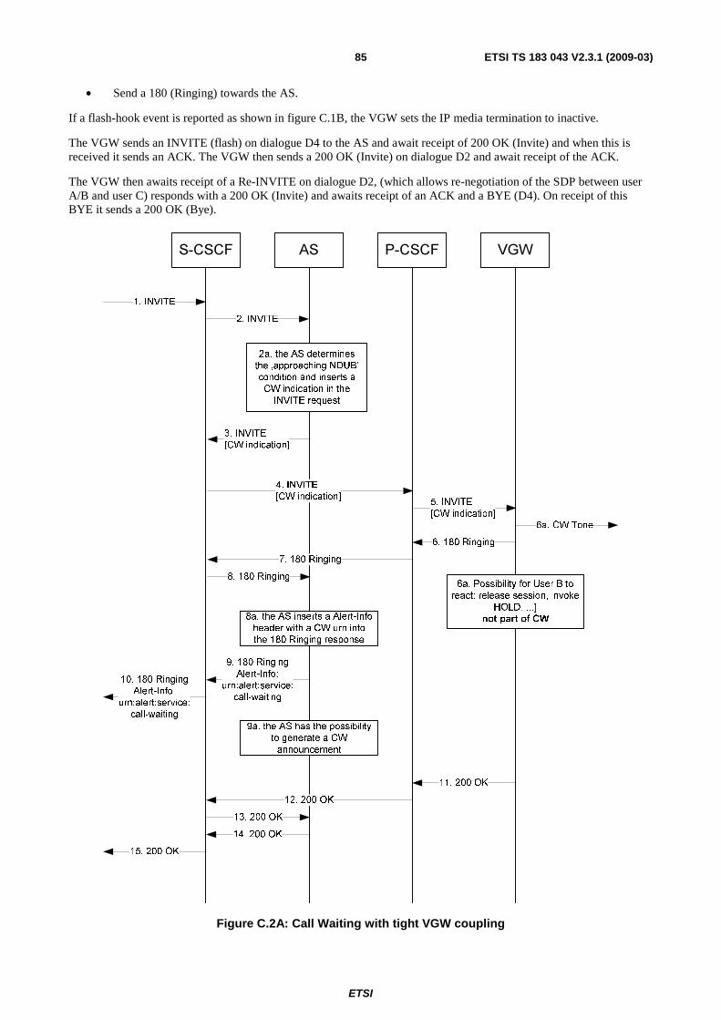
ETSI
ETSI TS 183 043 V2.3.1 (2009-03) 85
• Send a 180 (Ringing) towards the AS.
If a flash-hook event is reported as shown in figure C.1B, the VGW sets the IP media termination to inactive.
The VGW sends an INVITE (flash) on dialogue D4 to the AS and await receipt of 200 OK (Invite) and when this is received it sends an ACK. The VGW then sends a 200 OK (Invite) on dialogue D2 and await receipt of the ACK.
The VGW then awaits receipt of a Re-INVITE on dialogue D2, (which allows re-negotiation of the SDP between user A/B and user C) responds with a 200 OK (Invite) and awaits receipt of an ACK and a BYE (D4). On receipt of this BYE it sends a 200 OK (Bye).
S-CSCF P-CSCF VGW
2. INVITE
1. INVITE
5. INVITE
[CW indication]
AS
3. INVITE
[CW indication]
4. INVITE
[CW indication]
9a. the AS has the possibility
to generate a CW
announcement
9. 180 Ringing
Alert-Info:
urn:alert:service:
call-waiting
10. 180 Ringing
Alert-Info:
urn:alert:service:
call-waiting
6. 180 Ringing
7. 180 Ringing
8. 180 Ringing
2a. the AS determines
the ‚approaching NDUB’
condition and inserts a
CW indication in the
INVITE request
11. 200 OK
12. 200 OK
13. 200 OK
14. 200 OK
15. 200 OK
8a. the AS inserts a Alert-Info
header with a CW urn into
the 180 Ringing response
6a. Possibility for User B to
react: release session, invoke
HOLD, ...]
not part of CW
6a. CW Tone
Figure C.2A: Call Waiting with tight VGW coupling

ETSI
ETSI TS 183 043 V2.3.1 (2009-03) 86
C.10 Incoming Call Barring
C.10.1 Activation/Deactivation/Interrogation
C.10.1.1 Actions at the AGCF
Activation, deactivation and interrogation of incoming call barring is performed using service code commands as described in ETS 300 738 [12]. On receipt of a service code command, the AGCF sends an INVITE request as described in clause C.1.
C.10.1.2 Actions at the AS
On receipt of the INVITE request that includes a service code command as Request-URI, the AS proceeds as described in clause C.1.
C.10.1.3 Actions at the VGW
Activation, deactivation and interrogation of incoming call barring is performed using service code commands as described in ETS 300 738 [12]. On receipt of a service code command, the AGCF sends an INVITE request as described in clause C.1.
C.10.2 Invocation
C.10.2.1 Actions at the Originating AGCF
The originating AGCF is not involved in the invocation of the service.
C.10.2.2 Actions at the Originating AS
The originating AGCF is not involved in the invocation of the service.
C.10.2.3 Actions at the Terminating AS
On receipt of an INVITE request from a calling user, if incoming call barring is activated, the AS checks the P-Asserted-Identity against the list of allowed/forbidden calling parties. The rules and information used by the AS to evaluate whether the call is accepted are operator dependent. They may be compatible subset of the rules described in TS 183 011 [27].
If the call is rejected, the AS notifies the calling user by sending a 603 (Decline) response. Additionally, before terminating the communication an announcement can be provided to the originating user. The procedure for invoking an announcement in the call establishment phase is described within TS 183 028 [6].
C.10.2.4 Actions at the Terminating AGCF
The terminating AGCF is not involved in the provision of the service.
C.10.2.5 Actions at the Originating VGW
The originating VGW is not involved in the invocation of the service.
C.10.2.6 Actions at the Terminating VGW
The terminating VGW is not involved in the provision of the service.

ETSI
ETSI TS 183 043 V2.3.1 (2009-03) 87
C.11 Malicious Call Identification (Loose coupling)
C.11.1 Actions at the Originating AGCF The AGCF at the originating side is not involved in the provision of this service.
C.11.2 Actions at the Originating AS The AS at the originating side is not involved in the provision of this service.
C.11.3 Actions at the Terminating AS Support of the Malicious Call Identification (MCID) service requires that the AS providing the service is involved in all incoming calls to the served user.
On receipt of re-INVITE containing a MCID XML Request schema containing a McidRequestIndicator set to 1 or a re-INVITE not containing any Body, the AS registers the details of the last incoming call in a special record. Processing of this record is outside the scope of standardization.
Other Services that could use the re-INVITE not containing any Body as service invocation is disabled.
C.11.4 Actions at the Terminating AGCF As a network option, the AGCF may use the annex A Profile Delivery mechanism for obtaining the subscriber MCID subscription status (provisioned/withdrawn).
In case of invoking the MCID via a special service code command sent from the user the AGCF sends a re-INVITE without any body.
As a network operator option a re-INVITE including a XML-MIME with XML mcid body with MCID XML Request schema containing a McidRequestIndicator set to 1 may be sent.
C.11.5 Actions at the Originating VGW The VGW at the originating side is not involved in the provision of this service.
C.11.6 Actions at the Terminating VGW As a network option, the VGW may use the annex A Profile Delivery mechanism for obtaining the subscriber MCID subscription status (provisioned/withdrawn).
In case of invoking the MCID via a special service code command sent from the user the VGW sends a re-INVITE without any body.
As a network operator option a re-INVITE including a XML-MIME with XML mcid body with MCID XML Request schema containing a McidRequestIndicator set to 1 may be sent.
C.11A Malicious Call Identification (Tight coupling)
C.11A.1 Actions at the Originating AGCF The AGCF at the originating side is not involved in the provision of this service.

ETSI
ETSI TS 183 043 V2.3.1 (2009-03) 88
C.11A.2 Actions at the Originating AS The AS at the originating side is not involved in the provision of this service.
C.11A.3 Actions at the Terminating AS Support of the Malicious Call Identification (MCID) service requires that the AS providing the service is involved in all incoming calls to the served user.
On receipt of a service code command requesting invocation of the MCID service, the AS registers the details of the last incoming call in a special record. Processing of this record is outside the scope of standardization.
If the service command used within the re-INVITE is containing a flash hook (such as flash@pes scc.operator.com), then other services using flash-hook as invocation of the service is disabled for this terminating user.
C.11A.4 Actions at the Terminating AGCF The MCID service is invoked using a special service code command dialled after the malicious call is released.
On receipt of this service code command, the AGCF sends an INVITE request as described in clause C.1.
As an option a flash hook (such as flash@pes scc.operator.com) as service command can be used. The received flash-hook is processed as described within clause C.1.2.1.2 and a re-INVITE is sent the terminating AS.
C.11A.5 Actions at the Originating VGW The VGW at the originating side is not involved in the provision of this service.
C.11A.6 Actions at the Terminating VGW The MCID service is invoked using a special service code command dialled after the malicious call is released.
On receipt of this service code command, the VGW sends an INVITE request as described in clause C.1.
As an option a flash hook (such as flash@pes scc.operator.com) as service command can be used. The received flash-hook is processed as described within clause C.1.2.1.2 and a INVITE is sent to the terminating AS.
C.12 Message Waiting Indicator
C.12.1 Actions at the AGCF On receipt of a NOTIFY request reporting the "message-summary" event, the AGCF requests the following actions from the media gateway:
• Modify the default dial tone.
• Send a Message Waiting Indicator message (see EN 200 659-3 [10]) using the H.248 andisp/data signal.
C.12.2 Actions at the AS The AS implements the procedures described in TS 183 006 [26].
Generation of the Message Waiting Indicator message (see EN 200 659-3 [10]) by the AGCF is described in annex D.

ETSI
ETSI TS 183 043 V2.3.1 (2009-03) 89
C.12.3 Actions at the VGW On receipt of a NOTIFY request reporting the "message-summary" event, the VGW:
• Modify the default dial tone.
Send a Message Waiting Indicator message (see EN 200 659-3 [10]).
C.13 Outgoing Call Barring
C.13.1 Activation/Deactivation/Interrogation
C.13.1.1 Actions at the AGCF
Activation and deactivation of outgoing call barring is performed using service code commands as described in ETS 300 738 [12]. On receipt of a service code command, the AGCF sends an INVITE request as described in clause C.1.
C.13.1.2 Actions at the AS
On receipt of the INVITE request that includes a service code command as Request-URI, the AS proceeds as described in clause C.1.
C.13.1.3 Actions at the VGW
Activation and deactivation of outgoing call barring is performed using service code commands as described in ETS 300 738 [12]. On receipt of a service code command, the VGW sends an INVITE request as described in clause C.1.
C.13.2 Invocation
C.13.2.1 Actions at the Originating AGCF
The originating AGCF is not involved in the invocation of the service.
C.13.2.2 Actions at the Originating AS
On receipt of an INVITE request from a calling user, if outgoing call barring is activated, the AS checks the Request-URI against the list of allowed/forbidden called destinations. The rules and information used by the AS to evaluate whether the call is accepted are operator dependent. They may be compatible subset of the rules described in TS 183 011 [27].
If the call is rejected, the AS notifies the calling user by sending a 603 (Decline) response. Additionally, before terminating the communication an announcement can be provided to the originating user. The procedure for invoking an announcement in the call establishment phase is described within TS 183 028 [6].
C.13.2.3 Actions at the Terminating AS
The terminating AS is not involved in the provision of the service.
C.13.2.4 Actions at the Terminating AGCF
The terminating AGCF is not involved in the provision of the service.

ETSI
ETSI TS 183 043 V2.3.1 (2009-03) 90
C.13.2.5 Actions at the Originating VGW
The originating VGW is not involved in the invocation of the service.
C.13.2.6 Actions at the Terminating VGW
The terminating VGW is not involved in the provision of the service.
C.14 Three Party Service
C.14.0 General Processing of the switching order command depends on whether loose or tight coupling procedures are applied between the AGCF and the AS. Moreover, in loose coupling case, two methods can be used: the INVITE method, described in clause C.14.2, and the REFER method, described in clause C.14.2A. Figure C.4 illustrates the loose coupling case with the INVITE method while figure C.5 illustrates the loose coupling case with the REFER method. The tight coupling case is described in clause C.14.3.
C.14.1 General for Loosely Coupled Options
C.14.1.1 Actions at the AGCF at the service invocation side
The service is invoked during a stable 2 party call (without any waiting/held call) using the Register Recall. Figure C.3 illustrates the message sequence between the AGCF and the AS.
On receipt of a NOTIFY request reporting a flash-hook event, the AGCF performs the following actions unless an explicit indication that the HOLD service is not provisioned to the user has been previously received as part of the profile delivery procedure:
• Request the media gateway to play a dial tone on the physical and collect digits.
• Send a re-INVITE request to place the current call on hold.
On receipt of the dialled digits, the AGCF opens a new dialogue by sending an INVITE request with the following elements:
• The dialled digits used as a Request-URI.
• An SDP Offer for a voice call.
The AGCF then requests the media gateway to perform the following actions:
• monitor the flash-hook event;
• set the stream-mode of the ephemeral termination to "inactive"; and
• waits for a n incoming SIP message.
On receipt of 180 (Ringing) without P-Early-Media header or with a P-Early-Media header set to a value different from "sendonly" or from "sendreceive", the AGCF performs the following actions:
• Request the media gateway to play a ringback tone.
On receipt of 180 (Ringing) or 183 (Session Progress) with a P-Early-Media header set to "sendonly" or "sendreceive", the AGCF performs the following actions:
• Request the media gateway to modify the configuration of the ephemeral termination so as to ensure that the end user will perceive early media.

ETSI
ETSI TS 183 043 V2.3.1 (2009-03) 91
On receipt of an SDP Answer in a 200 (OK) or in one of the above provisional responses, the AGCF performs the following actions:
• Request the media gateway to modify the Remote Descriptor of the ephemeral termination associated with the physical termination representing the analogue line.
On receipt of a re-INVITE request requesting a call to be placed on hold, the AS applies the procedures described in TS 183 010 [8].
C.14.1.2 Actions at the AS at the service invocation side
Support of this service requires that all outgoing and incoming calls to the served user be handled by the same AS.
On receipt of a service code command requesting a three party conference, the AS may check that this request is compatible with subscription data held in the user profile. If the user is not entitled to use this service, the AS interacts with an MRFC is order to play an announcement to the invoker and sends a negative response to the re-INVITE request.
On receipt of a re-INVITE request with an SDP "a=sendonly" attribute, the AS may interact with an MRFC in order to play an announcement to the held party, in accordance with TS 183 028 [6].

ETSI
ETSI TS 183 043 V2.3.1 (2009-03) 92
MG AGCF ASTE
(1) H.248 interaction to monitor flash-hook events
(4) NOTIFY
(2) Register Recall
(8) H.248 interaction to apply dial tone and
collect digits
(9) Dial Tone
(10) Digits
(11)Digit(s) detected
(12) NOTIFY
(17) H.248 Remote Descriptor set to SDP-C
(3) Flash-hook detected
(13) INVITE (D2, digits@pes)
(5) RE-INVITE (D1, SDP a=send-only)
(7) Interaction with held party
(e.g. announcement)
(6) H.248 Stream ModeSet to send-only
(14) 183 Session Progress (D2)
(15) 180 Alerting (D2)
(16) 200 OK (D2, SDP-C)
(18) H.248 interaction for monitoring flash-hook
events
Figure C.3: Initiating a 3-Party call
C.14.1.3 Actions at the VGW at the service invocation side
The service is invoked during a stable 2 party call (without any waiting/held call) using the Register Recall. Figure C.3 illustrates the message sequence between the VGW and the AS.
On receipt of a flash-hook event, the VGW performs the following actions unless an explicit indication that the HOLD service is not provisioned to the user has been previously received as part of the profile delivery procedure:
• Play a dial tone on the physical and collect digits.
• Send a re-INVITE request to place the current call on hold.

ETSI
ETSI TS 183 043 V2.3.1 (2009-03) 93
On receipt of the dialled digits, the VGW opens a new dialogue by sending an INVITE request with the following elements:
• The dialled digits used as a Request-URI.
• An SDP Offer for a voice call.
The VGW then perform the following actions:
• monitor the flash-hook event;
• set the stream-mode of the IP media termination to "inactive"; and
• waits for an incoming SIP message.
On receipt of 180 (Ringing) without P-Early-Media header or with a P-Early-Media header set to a value different from "sendonly" or from "sendreceive", the VGW performs the following actions:
• Play a ringback tone.
On receipt of 180 (Ringing) or 183 (Session Progress) with a P-Early-Media header set to "sendonly" or "sendreceive", the VGW performs the following actions:
• Modify the configuration of the IP media termination so as to ensure that the end user will perceive early media.
On receipt of an SDP Answer in a 200 (OK) or in one of the above provisional responses, the VGW performs the following actions:
• Modify the IP media termination associated with the physical termination representing the analogue line.
On receipt of a re-INVITE request requesting a call to be placed on hold, the AS applies the procedures described in TS 183 010 [8].
Processing of the switching order command depends on whether loose or tight coupling procedures are applied between the VGW and the AS. Moreover, in loose coupling case, two methods can be used: with the INVITE method, described in clause C.14.2, and with the REFER method, described in clause C.14.2A. Figure C.4 illustrates the loose coupling case with the INVITE method while figure C.5 illustrates the loose coupling case with the REFER method. The tight coupling case is described in clause C.14.3.
C.14.2 Loose coupling Option1 with INVITE method
C.14.2.1 Actions at the AGCF at the invoking side
The AGCF evaluates the Switch Order Command based on a provisioned mapping table.
If the feature code received from the internal MGC component does not match any known feature, the AGCF ignores the feature code and optionally request the media gateway to play an error tone or an announcement to the served user.
As a network option the AGCF can evaluate a Switch Order Command based on a provisioned mapping table to correct a preceding Switch Order Command that was wrong.
If the SOC indicates that the user wishes to establish a 3-party conference with the held parties. the AGCF performs the following actions unless an explicit indication that the 3PTY service is not provisioned to the user has been previously received as part of the profile delivery procedure:
• Request the media gateway to:
- Add a termination to the current context based on SDP information associated with the held party.
- Monitor the flash-hook event.

ETSI
ETSI TS 183 043 V2.3.1 (2009-03) 94
• Send a re-INVITE request towards the first held party (i.e. the party that was already held when the flash-hook event was detected). The re-INVITE request is built as follows:
- The Request URI is set to the held party's identity.
- The SDP description is set to a=sendrecv. The address and port are set according to the contents of the local descriptor of the new termination.
• Send a re-INVITE request towards the second held party (i.e. the party that has been held for the purpose of collecting the Switch Order Command). The re-INVITE request is built as follows:
- The Request URI is set to the held party's identity.
- The SDP description is set to a=sendrecv.
Once the 3-party call is established with the waiting party, processing of the flash-hook event is similar to the call waiting service. If SOC indicates that the served user wishes to reject one of the parties, the AGCF performs the following actions:
• Send a BYE request towards the held party.
• Request the media gateway to:
- Remove the corresponding ephemeral termination.
- Monitor the flash-hook event.
C.14.2.2 Actions at the Originating AS at the invoking side
On receipt of a re-INVITE request with an SDP attribute "sendonly", the AS may interact with an MRFC in order to play an announcement to the held party, in accordance with TS 183 028 [6].
On receipt of a re-INVITE request with the SDP attribute "sendrecv", the AS interacts with the MRFC to stop any ongoing announcement.
On receipt of a BYE request, the AS releases the dialogue with the associated party.

ETSI
ETSI TS 183 043 V2.3.1 (2009-03) 95
M G AGCF AST E
(3) NOTIFY
(1)
(5) H.248 Remote descrip tor set to SDP-C
Digits
(2) Dig itsdetected
(7) re-INVITE (D1, SDP a=sendrecv)
(4) Evaluate switch order code
(10) 200 OK
(6) H.248 interaction for monitoring flash-hook events
(9 ) Stop announcement
(8) H.248 Stream mode s et to send&receive
(11) re-INVITE (D2, SDP a=sendrecv)
(13) Stop announcement
(12) H.248 Stream mode s et to send&receive
(13) 200 OK
Figure C.4: 3PTY with INVITE method
C.14.2.3 Actions at the VGW at the invoking side
The VGW evaluates the Switch Order Command based on a provisioned mapping table.
If the feature code received does not match any known feature, the VGW ignores the feature code and optionally play an error tone or an announcement to the served user.
If the SOC indicates that the user wishes to establish a 3-party conference with the held parties. The VGW performs the following actions unless an explicit indication that the 3PTY service is not provisioned to the user has been previously received as part of the profile delivery procedure:
• The VGW:
- Add a termination to the current context based on SDP information associated with the held party.
- Monitor the flash-hook event.

ETSI
ETSI TS 183 043 V2.3.1 (2009-03) 96
• Send a re-INVITE request towards the first held party (i.e. the party that was already held when the flash-hook event was detected). The re-INVITE request is built as follows:
- The Request URI is set to the held party's identity.
- The SDP description is set to a=sendrecv. The address and port are set according to the IP media termination.
• Send a re-INVITE request towards the second held party (i.e. the party that has been held for the purpose of collecting the Switch Order Command). The re-INVITE request is built as follows:
- The Request URI is set to the held party's identity.
- The SDP description is set to a=sendrecv.
Once the 3-party call is established with the waiting party, processing of the flash-hook event is similar to the call waiting service. If SOC indicates that the served user wishes to reject one of the parties, the VGW performs the following actions:
• Send a BYE request towards the held party.
• The VGW:
- Remove the corresponding IP media termination.
- Monitor the flash-hook event.
C.14.2A Loose coupling Option 2 with REFER method
C.14.2A.1 Actions at the AGCF at the invoking side
The AGCF evaluates the Switch Order Command based on a provisioned mapping table.
If the feature code received from the internal MGC component does not match any known feature, the AGCF ignores the feature code and optionally request the media gateway to play an error tone or an announcement to the served user.
As a network option the AGCF can evaluate a Switch Order Command based on a provisioned mapping table to correct a preceding Switch Order Command that was wrong.
If the SOC indicates that the user wishes to establish a 3-party conference with the held parties, the AGCF performs the following actions unless an explicit indication that the 3PTY service is not provisioned to the user has been previously received as part of the profile delivery procedure:
• Request the media gateway to:
- Add a termination to the current context based on SDP information associated with the held party.
- Monitor the flash-hook event.
• Send an initial INVITE with the To and the Request-URI containing the Conference bridge URI provisioned in the AGCF.
• Send a REFER request within the existing dialog with user B with the Refer-To header containing the Conference bridge contact URI and the dialog associated with the B party. The ReferredBy header field is set to the served user's identity.
• Send a REFER request within the existing dialog with user C with the Refer-To header containing the Conference bridge contact URI and the dialog associated with the C party. The ReferredBy header field is set to the served user's identity.
NOTE: The REFER sent is built as specified in RFC 3515 [i.5] without any body. Unlike specified in RFC 3515 [i.5] the terminal will not receive any NOTIFY (see RFC 4488 [i.3]).

ETSI
ETSI TS 183 043 V2.3.1 (2009-03) 97
When the SIP end-point receives 202 ACCEPTED response to each sent REFER request, it:
• performs conference establishment notification;
• considers only the call established with the conference bridge as active.
The SIP end-point will receive a BYE message in both call established.
Once the 3-party call is established with the waiting party, processing of the flash-hook event is similar to the call waiting service. If SOC indicates that the served user wishes to reject one of the parties, the AGCF performs the following actions:
• Send a BYE request towards the held party.
• Request the media gateway to:
- Remove the corresponding ephemeral termination.
- Monitor the flash-hook event.
C.14.2A.2 Actions at the Originating AS at the invoking side
Upon reception of the INVITE addressed to the conference bridge, the AS forwards to the MRFC the INVITE request with SDP offer populated with user information.
Upon reception of the first REFER, the AS:
• Sends an INVITE message to the bridge with SDP offer populated with first held party information.
• Sends a re-INVITE request towards the first held party (i.e. the party that was already held when the flash-hook event was detected). The re-INVITE request is built as follows:
- The Request URI is set to the held party's identity.
- The SDP description is set to a=sendrecv. The address and port are set according to the contents of the local descriptor of the new termination.
• Sends a BYE message to the served-user for end his call with the first held party.
Upon reception of the other REFER, the AS:
• Sends an INVITE message with SDP offer populated with the second held party information.
• Sends a re-INVITE request towards the second held party (i.e. the party that has been held for the purpose of collecting the Switch Order Command). The re-INVITE request is built as follows:
- The Request URI is set to the held party's identity.
- The SDP description is set to a=sendrecv.
• Sends a BYE message to the served-user for end his call with the second held party.

ETSI
ETSI TS 183 043 V2.3.1 (2009-03) 98
MG AGCF ASTE
(3) NOTIFY
(1)
(5) H.248 Remote descriptor set to SDP-C
Digits
(2)Digitsdetected
(7) INVITE (Conf Bridge URI)
(4) Evaluate switch order code
(9) 200 OK
(6) H.248 interaction for monitoring flash-hook events
(10) REFER (ReferTo: Conf Bridge URI, replaces dialog B)
(14) BYE (A)
(8) INVITE (MRFC)
(11) 202 Accepted(12) INVITE (MRFC)
(13) re-INVITE (B, SDP a=sendrecv)
(15) REFER (ReferTo: Conf Bridge URI, replaces dialog C)
(16) 202 Accepted
(17) INVITE (MRFC)
(18) re-INVITE (C, SDP a=sendrecv)
(19) BYE (A)
Figure C.5: 3PTY with REFER method
C.14.2A.3 Actions at the VGW at the invoking side
The VGW evaluates the Switch Order Command based on a provisioned mapping table.
If the feature code received does not match any known feature, the VGW ignores the feature code and optionally play an error tone or an announcement to the served user.
If the SOC indicates that the user wishes to establish a 3-party conference with the held parties, the VGW performs the following actions unless an explicit indication that the 3PTY service is not provisioned to the user has been previously received as part of the profile delivery procedure:
• The VGW:
- Add a termination to the current context based on SDP information associated with the held party.

ETSI
ETSI TS 183 043 V2.3.1 (2009-03) 99
- Monitor the flash-hook event.
• Send an initial INVITE with the To and the Request-URI containing the Conference bridge URI provisioned in the VGW.
• Send a REFER request within the existing dialog with user B with the Refer-To header containing the Conference bridge contact URI and the dialog associated with the B party. The ReferredBy header field is set to the served user's identity.
• Send a REFER request within the existing dialog with user C with the Refer-To header containing the Conference bridge contact URI and the dialog associated with the C party. The ReferredBy header field is set to the served user's identity.
NOTE: The REFER sent is built as specified in RFC 3515 [i.5] without any body. Unlike specified in RFC 3515 [i.5] the terminal will not receive any NOTIFY (see RFC 4488 [i.3]).
When the SIP end-point receives 202 ACCEPTED response to each sent REFER request, it:
• performs conference establishment notification;
• consider only the call established with the conference bridge as active.
The SIP end-point will receive a BYE message in both call established.
Once the 3-party call is established with the waiting party, processing of the flash-hook event is similar to the call waiting service. If SOC indicates that the served user wishes to reject one of the parties, the VGW performs the following actions:
• Send a BYE request towards the held party.
• The VGW proceed with the following procedures:
- Remove the corresponding IP media termination.
- Monitor the flash-hook event.
C.14.2B Loose coupling Option 3 by sending INVITE request with URI list
C.14.2B.1 Actions at the AGCF at the invoking side
The AGCF evaluates the Switch Order Command based on a provisioned mapping table.
If the feature code received does not match any known feature, the AGCF ignores the feature code and optionally to play an error tone or an announcement to the served user. Or initiate an announcement due to the procedures described within TS 183 028 [6].
As a network option the AGCF can evaluate a Switch Order Command based on a provisioned mapping table to correct a preceding Switch Order Command that was wrong.
If the SOC indicates that the user wishes to establish a 3-party conference with the held parties the AGCF performs the following actions unless an explicit indication that the 3PTY service is not provisioned to the user has been previously received as part of the profile delivery procedure:
AGCF creates a conference and invites user B and user C to the conference by sending an INVITE to the Conference Factory URI and including URI list in the INVITE request, AGCF indicates the certain dialogs which be re-used for this conference in the uri list by ? mechanism.

ETSI
ETSI TS 183 043 V2.3.1 (2009-03) 100
INVITE CONF AS To: CONF AS From: A Require: recipient-list-invite Content-Type: application/resource-lists+xml Content-Disposition: recipient-list <?xml version="1.0" encoding="UTF-8"?> <resource-lists xmlns="urn:ietf:params:xml:ns:resource-lists" xmlns:cp="urn:ietf:params:xml:ns:copyControl"> <list> <entry uri="B?Call-ID=1a&From=A%3Btag%3Da&To=B%3Btag%3Db" cp:copyControl="to"/> <entry uri="C?Call-ID=2a&From=A%3Btag%3Da&To=C%3Btag%3Dc" cp:copyControl="to"/> </list> </resource-lists>
Once the 3-party call is established with the waiting party, processing of the flash-hook event is similar to the call waiting service. If SOC indicates that the served user wishes to reject one of the parties, the AGCF performs the following actions:
• Send a BYE request towards the Conference Server.
• Send a BYE request towards on the held dialog of the party that should be disconnected.
• Send a Re-INVITE on the other held party to reactivate that dialog.
• Monitor the flash-hook event.
C.14.2B.2 Actions at the Originating AS at the invoking side
AS verifies if the dialogs in URI list matches to a partial dialog which AS already involved, In the case of a match the AS use this dialog ID information to send re-INVITE request to UA-B and UA-C in the partial dialogs between the AS and the invited users in order to connect the media of the invited users to the MRFP.
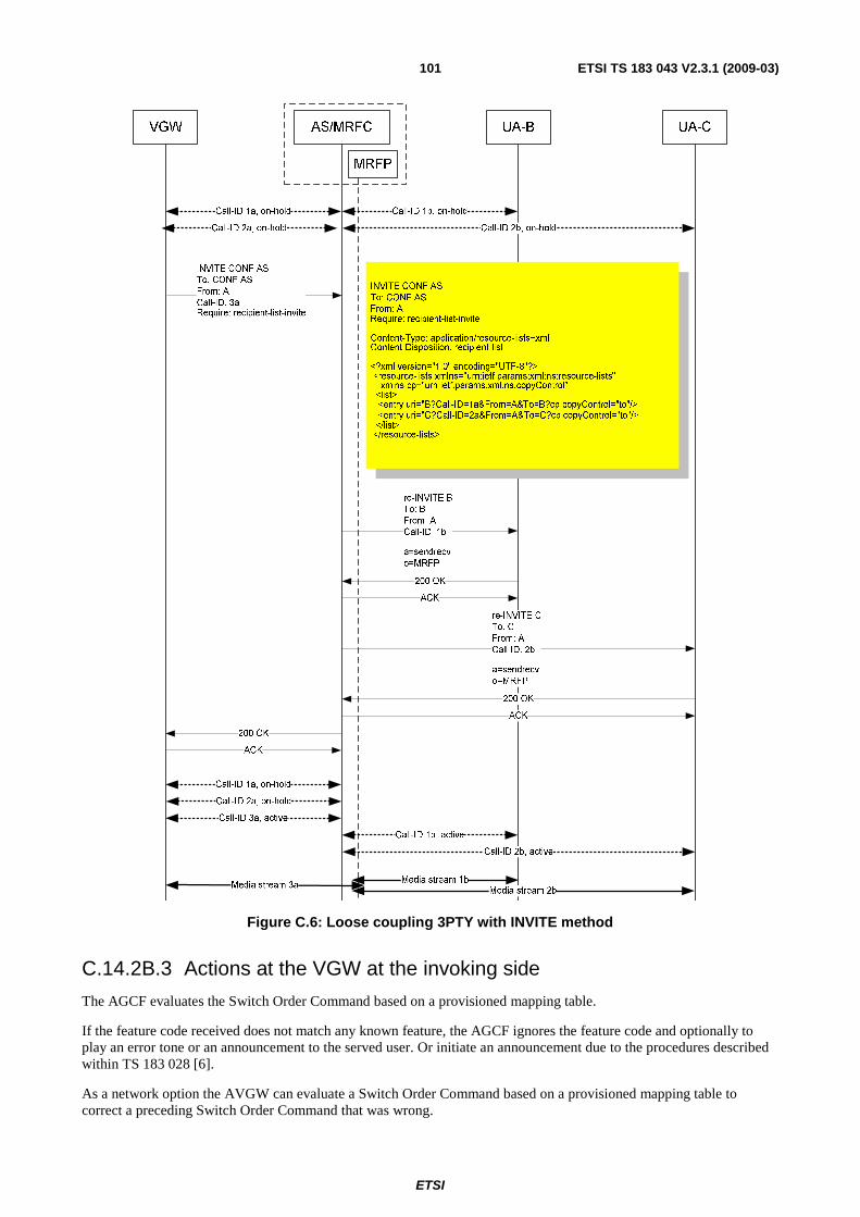
ETSI
ETSI TS 183 043 V2.3.1 (2009-03) 101
Figure C.6: Loose coupling 3PTY with INVITE method
C.14.2B.3 Actions at the VGW at the invoking side
The AGCF evaluates the Switch Order Command based on a provisioned mapping table.
If the feature code received does not match any known feature, the AGCF ignores the feature code and optionally to play an error tone or an announcement to the served user. Or initiate an announcement due to the procedures described within TS 183 028 [6].
As a network option the AVGW can evaluate a Switch Order Command based on a provisioned mapping table to correct a preceding Switch Order Command that was wrong.
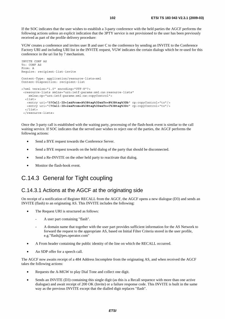
ETSI
ETSI TS 183 043 V2.3.1 (2009-03) 102
If the SOC indicates that the user wishes to establish a 3-party conference with the held parties the AGCF performs the following actions unless an explicit indication that the 3PTY service is not provisioned to the user has been previously received as part of the profile delivery procedure:
VGW creates a conference and invites user B and user C to the conference by sending an INVITE to the Conference Factory URI and including URI list in the INVITE request, VGW indicates the certain dialogs which be re-used for this conference in the uri list by ? mechanism.
INVITE CONF AS To: CONF AS From: A Require: recipient-list-invite Content-Type: application/resource-lists+xml Content-Disposition: recipient-list <?xml version="1.0" encoding="UTF-8"?> <resource-lists xmlns="urn:ietf:params:xml:ns:resource-lists" xmlns:cp="urn:ietf:params:xml:ns:copyControl"> <list> <entry uri="B?Call-ID=1a&From=A%3Btag%3Da&To=B%3Btag%3Db" cp:copyControl="to"/> <entry uri="C?Call-ID=2a&From=A%3Btag%3Da&To=C%3Btag%3Dc" cp:copyControl="to"/> </list> </resource-lists>
Once the 3-party call is established with the waiting party, processing of the flash-hook event is similar to the call waiting service. If SOC indicates that the served user wishes to reject one of the parties, the AGCF performs the following actions:
• Send a BYE request towards the Conference Server.
• Send a BYE request towards on the held dialog of the party that should be disconnected.
• Send a Re-INVITE on the other held party to reactivate that dialog.
• Monitor the flash-hook event.
C.14.3 General for Tight coupling
C.14.3.1 Actions at the AGCF at the originating side
On receipt of a notification of Register RECALL from the AGCF, the AGCF opens a new dialogue (D3) and sends an INVITE (flash) to an originating AS. This INVITE includes the following:
• The Request URI is structured as follows:
- A user part containing "flash".
- A domain name that together with the user part provides sufficient information for the AS Network to forward the request to the appropriate AS, based on Initial Filter Criteria stored in the user profile, e.g."[email protected]"
• A From header containing the public identity of the line on which the RECALL occurred.
• An SDP offer for a speech call.
The AGCF now awaits receipt of a 484 Address Incomplete from the originating AS, and when received the AGCF takes the following actions:
• Requests the A-MGW to play Dial Tone and collect one digit.
• Sends an INVITE (D3) containing this single digit (as this is a Recall sequence with more than one active dialogue) and await receipt of 200 OK (Invite) or a failure response code. This INVITE is built in the same way as the previous INVITE except that the dialled digit replaces "flash".
ETSI
ETSI TS 183 043 V2.3.1 (2009-03) 103
The AGCF then awaits a re-INVITE (D2) with the SDP of a Media Server in the AS Network (acting as a 3 party bridge) and when received it takes the following actions:
• Sends an instruction to the A-MGW to change the address to which RTP packets are sent and from which they are received (e.g. it modifies the H.248 Remote Descriptor).
Sends a 200 OK (Invite) to the AS, awaits receipt of a BYE to end dialogue D3, and when this is received it sends a 200 OK (Bye).
C.14.3.2 Actions at the Originating AS at the originating side
On receipt of an INVITE (flash) (D3) the AS takes the following actions:
• Sends a 484 Address Incomplete response to the AGCF and awaits receipt of an ACK.
• Awaits receipt of an INVITE (D3) with a single digit and when this is received sends a 200 OK (Invite) to the AGCF and awaits receipt of the ACK.
• Sends a Re-INVITE (D2) with the SDP of a Media Server (acting as a 3 party bridge) to the AGCF, awaits a 200 OK (Invite) and when this is received it sends an ACK followed by a BYE (D3).
• It then awaits a 200 OK (Bye).

ETSI
ETSI TS 183 043 V2.3.1 (2009-03) 104
Figure C.7: 3PTY Call Establishment for tight coupling

ETSI
ETSI TS 183 043 V2.3.1 (2009-03) 105
C.14.3.3 Actions at the VGW at the originating side
On receipt of a notification of Register RECALL from the VGW, the VGW opens a new dialogue (D3) and sends an INVITE (flash) to an originating AS. This INVITE includes the following:
• The Request URI is structured as follows:
- A user part containing "flash".
- A domain name that together with the user part provides sufficient information for the AS Network to forward the request to the appropriate AS, based on Initial Filter Criteria stored in the user profile, e.g. [email protected].
• A From header containing the public identity of the line on which the RECALL occurred.
• An SDP offer for a speech call.
The VGW now awaits receipt of a 484 Address Incomplete from the originating AS, and when received the VGW takes the following actions:
• Play Dial Tone and collect one digit.
• Sends an INVITE (D3) containing this single digit (as this is a Recall sequence with more than one active dialogue) and await receipt of 200 OK (Invite) or a failure response code. This INVITE is built in the same way as the previous INVITE except that the dialled digit replaces "flash".
The VGW then awaits a re-INVITE (D2) with the SDP of a Media Server in the AS Network (acting as a 3 party bridge) and when received it takes the following actions:
• Change the address to which RTP packets are sent and from which they are received.
Sends a 200 OK (Invite) to the AS, awaits receipt of a BYE to end dialogue D3, and when this is received it sends a 200 OK (Bye).
C.15 Repeat Last Call
C.15.1 AGCF at the served user side The Repeat Last Call service is invoked using a service code command. On receipt of this service code command, the AGCF builds an INVITE request as described in clause C.1.
C.15.2 AS at the served user side Implementation of this service assumes that the AS providing the service is involved in all outgoing calls to the served user. It is the responsibility of the network operator to configure the appropriate Initial Filter Criteria in the user profile. The AS keeps track of the last incoming call to each served user it manages.
When receiving the service code command that identifies the Repeat Last Call service, the AS acts as a B2BUA and establishes a new call leg to the last called party (i.e. it sends an INVITE messages towards this last called party as if the number had been dialled again by the served user).
C.15.3 VGW at the served user side The Repeat Last Call service is invoked using a service code command. On receipt of this service code command, the VGW builds an INVITE request as described in clause C.1.
ETSI
ETSI TS 183 043 V2.3.1 (2009-03) 106
C.16 Call Hold
C.16.1 Option 1 (Loose Coupling)
C.16.1.1 Actions at the AGCF at the service invocation side
The service is invoked during a stable 2 party call using the Register Recall.
The AGCF monitors the flash-hook event unless an explicit indication that the Hold service is not provisioned to the user has been previously received as part of the profile delivery procedure.
On receipt of a NOTIFY request reporting a flash hook event, the AGCF performs the following actions:
• Monitor the flash-hook event.
• Send a re INVITE request to place the current call on hold.
On receipt of a NOTIFY request reporting a flash hook event, the AGCF performs the following actions:
• Send a re INVITE request to resume the call on hold.
• Monitor the flash-hook event.
On receipt of a re INVITE request requesting a call to be placed on hold, the AS applies the procedures described in TS 183 010 [8].
As a network option the AS of the invoking UE initiates the procedures for the provision of an announcement to the held user in accordance with TS 183 028 [6].
C.16.1.2 Actions at the AS at the service invocation side
On receipt of a re INVITE request requesting a call to be placed on hold, the AS applies the procedures described in TS 183 010 [8].
As a network option the AS of the invoking UE initiates the procedures for the provision of an announcement to the held user in accordance with TS 183 028 [6].
C.16.1.3 Actions at the VGW at the service invocation side
The service is invoked during a stable 2 party call using the Register Recall.
The VGW monitors the flash-hook event unless an explicit indication that the Hold service is not provisioned to the user has been previously received as part of the profile delivery procedure.
On receipt of a NOTIFY request reporting a flash hook event, the VGW performs the following actions:
• Monitor the flash-hook event.
• Send a re INVITE request to place the current call on hold.
On receipt of a NOTIFY request reporting a flash hook event, the VGW performs the following actions:
• Send a re INVITE request to resume the call on hold.
• Monitor the flash-hook event.
On receipt of a re INVITE request requesting a call to be placed on hold, the AS applies the procedures described in TS 183 010 [8].
As a network option the AS of the invoking UE initiates the procedures for the provision of an announcement to the held user in accordance with TS 183 028 [6].

ETSI
ETSI TS 183 043 V2.3.1 (2009-03) 107
C.16.2 Option 2 (Tight Coupling)
C.16.2.1 Actions at the AGCF at the service invocation side
The service is invoked during a stable 2 party call using the Register Recall.
The handling of the resulting Feature Request in the AGCF is according to clause B.4.2.2.3. The AGCF only reports the flash-hook as a trigger to the AS which has to take and co-ordinate all following actions dependent on the current service configuration.
As a network option the AS of the invoking UE initiates the procedures for the provision of an announcement to the held user in accordance with TS 183 028 [6].
C.16.2.2 Actions at the AS at the service invocation side
For tight coupling procedures the control of flash-hook invoked services is fully under control of the Application Server. As a consequence the AGCF/VGW only reports the flash-hook as a trigger to the AS which has to take and co-ordinate all following actions dependent on the current service configuration.
In the context of 3 way call services the initial INVITE (flash) as described in clause B.4.2.2.3 only triggers the AS to place the current call on hold. Hold and resumption scenarios are specified in the supplementary service specific clauses of annex C.
As a network option the AS of the invoking UE initiates the procedures for the provision of an announcement to the held user in accordance with TS 183 028 [6].
C.16.2.3 Actions at the VGW at the service invocation side
The service is invoked during a stable 2 party call using the Register Recall.
The handling of the resulting Feature Request in the VGW is according to clause B.4.2.2.3. The VGW only reports the flash-hook as a trigger to the AS which has to take and co-ordinate all following actions dependent on the current service configuration.
As a network option the AS of the invoking UE initiates the procedures for the provision of an announcement to the held user in accordance with TS 183 028 [6].
C.17 Call Toggle/Broker Call Service
C.17.1 General
C.17.1.1 Actions at the AGCF at the service invocation side
The service is invoked having an active call and a held call using the Register Recall.
The AGCF monitors the flash-hook event.
C.17.1.2 Actions at the VGW at the service invocation side
The service is invoked having an active call and a held call using the Register Recall.
The VGW monitors the flash-hook event.

ETSI
ETSI TS 183 043 V2.3.1 (2009-03) 108
C.17.2 Option 1 (Loose coupling)
C.17.2.1 Actions at the AGCF
On receipt of a NOTIFY request reporting a flash hook event, the AGCF performs the following actions:
• Set the stream mode of the ephemeral termination to inactive.
• Apply a dial tone.
• Collect a switching order command.
The AGCF evaluates the Switch Order Command based on a provisioned mapping table.
If the feature code received from the internal MGC component does not match any known feature, the AGCF ignores the feature code and optionally request the media gateway to play an error tone or an announcement to the served user.
If the SOC indicates that the user wishes to toggle the active and the held parties the AGCF performs the following actions unless an explicit indication that the Call Toggle service is not provisioned for this user has been previously received as part of the profile delivery procedure:
• Send a re INVITE request towards the active party. The re INVITE request is built as follows:
- The Request URI is set to the active party's identity.
- The SDP description for the active media stream is set to a=sendonly.
• Send a re-INVITE request towards the former held party. The re-INVITE request is built as follows:
- The Request-URI is set to the held party's identity.
- The SDP description for the active media stream is set to a=sendrecv.
• Request the media gateway to:
- Modify the Remote Descriptor of the ephemeral termination according to the SDP information associated with the held party.
- Monitor the flash-hook event.
C.17.2.2 Actions at the AS at the terminating side
On receipt of a re-INVITE request with a SDP attribute "sendonly", the AS as a network option interacts with an MRFC is order to play an announcement to the held party, in accordance with TS 183 028 [6].
On receipt of a re-INVITE request with the SDP attribute "sendrecv", the AS interacts with the MRFC to stop any ongoing announcement.
C.17.2.3 Actions at the VGW
On receipt of a NOTIFY request reporting a flash hook event, the VGW performs the following actions:
• Set the stream mode of the IP media termination to inactive.
• Apply a dial tone.
• Collect a switching order command.
The VGW evaluates the Switch Order Command based on a provisioned mapping table.
If the feature code received does not match any known feature, the VGW ignores the feature code and optionally play an error tone or an announcement to the served user.

ETSI
ETSI TS 183 043 V2.3.1 (2009-03) 109
If the SOC indicates that the user wishes to toggle the active and the held parties the VGW performs the following actions unless an explicit indication that the Call Toggle service is not provisioned for this user has been previously received as part of the profile delivery procedure:
• Send a re INVITE request towards the active party. The re INVITE request is built as follows:
- The Request URI is set to the active party's identity.
- The SDP description for the active media stream is set to a=sendonly.
• Send a re-INVITE request towards the former held party. The re-INVITE request is built as follows:
- The Request-URI is set to the held party's identity.
- The SDP description for the active media stream is set to a=sendrecv.
• The VGW perform the following procedures:
- Modify the IP media termination according to the SDP information associated with the held party.
- Monitor the flash-hook event.
C.17.3 Option 2 (Tight coupling)
C.17.3.1 Actions at the AGCF
The AGCF sends a re-INVITE request to the Application Server on the active call, built as follows:
• The Request URI is structured as follows:
- A user part containing a provisioned prefix followed by the switching order command without the start and finish fields.
NOTE: In networks where no explicit SOC is collected, a preconfigured SOC is used to populate the user part.
• A domain name that provides sufficient information to the S-CSCF to forward the INVITE request to the appropriate AS, based on Initial Filter Criteria stored in the user profile, e.g. SOC- "SO (SR SI)"@pes.operator.com.
• A P-Asserted-Identity containing the public identity of the subscriber issuing the switching control command.
• An SDP offer for a voice call.
The AGCF modifies the H.248 Remote Descriptor and stream mode according to the SDP information received in re-INVITE messages sent by the Application Server.
C.17.3.2 Actions at the Originating AS at the originating side
The AS evaluates the Switch Order Command based on the current call configuration and issues appropriate re-INVITE messages putting the former active party on hold and resuming the former held party.
The AS interacts with an MRFC is order to play and stop announcements to held party, in accordance with TS 183 028 [6].
C.17.3.3 Actions at the VGW
The VGW sends a re-INVITE request to the Application Server on the active call, built as follows:
• The Request URI is structured as follows:
- A user part containing a provisioned prefix followed by the switching order command without the start and finish fields.

ETSI
ETSI TS 183 043 V2.3.1 (2009-03) 110
NOTE: In networks where no explicit SOC is collected, a preconfigured SOC is used to populate the user part.
• A domain name that provides sufficient information to the S-CSCF to forward the INVITE request to the appropriate AS, based on Initial Filter Criteria stored in the user profile, e.g. SOC- "SO (SR SI)"@pes.operator.com
• A P-Asserted-Identity containing the public identity of the subscriber issuing the switching control command.
• An SDP offer for a voice call.
The VGW modifies the stream mode according to the SDP information received in re-INVITE messages sent by the Application Server.
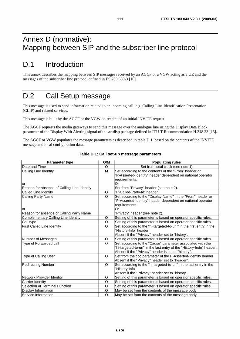
ETSI
ETSI TS 183 043 V2.3.1 (2009-03) 111
Annex D (normative): Mapping between SIP and the subscriber line protocol
D.1 Introduction This annex describes the mapping between SIP messages received by an AGCF or a VGW acting as a UE and the messages of the subscriber line protocol defined in ES 200 659-3 [10].
D.2 Call Setup message This message is used to send information related to an incoming call. e.g. Calling Line Identification Presentation (CLIP) and related services.
This message is built by the AGCF or the VGW on receipt of an initial INVITE request.
The AGCF requests the media gateways to send this message over the analogue line using the Display Data Block parameter of the Display With Alerting signal of the andisp package defined in ITU-T Recommendation H.248.23 [13].
The AGCF or VGW populates the message parameters as described in table D.1, based on the contents of the INVITE message and local configuration data.
Table D.1: Call set-up message parameters
Parameter type O/M Populating rules Date and Time O Set from local clock (see note 1) Calling Line Identity M Set according to the contents of the "From" header or
"P-Asserted-Identity" header dependent on national operator requirements.
or Or Reason for absence of Calling Line Identity Set from "Privacy" header (see note 2). Called Line Identity O "P-Called-Party-Id" header. Calling Party Name O Set according to the "Display-Name" in the "From" header or
"P-Asserted-Identity" header dependent on national operator requirements
or Or Reason for absence of Calling Party Name "Privacy" header (see note 2). Complementary Calling Line Identity O Setting of this parameter is based on operator specific rules. Call type O Setting of this parameter is based on operator specific rules. First Called Line Identity O Set according to the "hi-targeted-to-uri " in the first entry in the
"History-Info" header Absent if the "Privacy" header set to "history".
Number of Messages O Setting of this parameter is based on operator specific rules. Type of Forwarded call O Set according to the "Cause" parameter associated with the
"hi-targeted-to-uri" in the last entry of the "History-Indo" header. Absent if the "Privacy" header is set to "history".
Type of Calling User O Set from the cpc parameter of the P-Asserted-Identity header Absent if the "Privacy" header set to "header".
Redirecting Number O Set according to the "hi-targeted-to-uri" in the last entry in the "History-Info" Absent if the "Privacy" header set to "history".
Network Provider Identity O Setting of this parameter is based on operator specific rules. Carrier Identity O Setting of this parameter is based on operator specific rules. Selection of Terminal Function O Setting of this parameter is based on operator specific rules. Display Information O May be set from the contents of the message body. Service Information O May be set from the contents of the message body.

ETSI
ETSI TS 183 043 V2.3.1 (2009-03) 112
Parameter type O/M Populating rules Extension for network operator use O Setting of this parameter is based on operator specific rules. NOTE 1: The AGCF and the VGW shall support an appropriate clock synchronization mechanism. NOTE 2: If the "Privacy" header is included and set to "id" or "user" or "header", the Reason for Absence is set to
"Private" (0101 0000). If the "P-Asserted-Identity" header and the "From" header are absent, the Reason for Absence is set to "unavailable" (0100 1111).
D.3 Message Waiting Indicator message This message type is used to handle information related to messages in a message system.
This message is built by the AGCF or the VGW on receipt of a NOTIFY request reporting the "message-summary" event.
The AGCF requests the media gateways to send this message over the analogue line using the Data Block parameter of the Generic Data Signalling signal of the andisp package defined in ITU-T Recommendation H.248.23 [13]. The value of the TAS parameter is provisioned in the AGCF or MGF, per media gateway or per line.
The AGCF or the VGW populates the message parameters as described in table D.2, using the information contained in NOTIFY requests reporting the "message-summary" event and local configuration data.
Table D.2: Message Waiting Indicator message parameters
Parameter type O/M Populating rules Date and Time O Set from local clock (see note). Calling Line Identity Set according to the contents of the "P-Asserted-Id" header or Or Reason for absence of Calling Line Identity O Privacy header. Calling Party Name Set according to the "P-Asserted-Id" header or Or Reason for absence of Calling Party Name O "Privacy" header. Visual Indicator M Set to "FF"H if the "Messages-Waiting" header is set to "yes". Message Identification O Set according to the "Message-ID" header. Last Message CLI O "From" header associated with the last message. Complementary Date and Time O "Date" header associated with the last message. Complementary Calling Line Identity O Setting of this parameter is based on operator specific rules. Number of Messages O Set according to the "Voice-Message" header. Type of Calling User O Setting of this parameter is based on operator specific rules. Network Provider Identity O Setting of this parameter is based on operator specific rules. Selection of Terminal Function O Setting of this parameter is based on operator specific rules. Display Information O May be set from the contents of the message body. Extension for network operator use O Setting of this parameter is based on operator specific rules. NOTE: The AGCF and the UE shall support an appropriate clock synchronization mechanism.
D.4 Advice of Charge message This message is used to send information related to the charge of a call.
This message is built by the AGCF or the VGW on receipt of a SIP message that contain information defined in TS 183 047 [7].
The AGCF or the VGW populates the message parameters as described in table D.3, based on information defined in TS 183 047 [7] and local configuration data.

ETSI
ETSI TS 183 043 V2.3.1 (2009-03) 113
Table D.3: Advice Of Charge message parameters
Parameter type O/M Populated From Date and Time O Set from local clock (see note). Calling Line Identity O or Setting of this parameter is based on operator specific rules. Reason for absence of Calling Line Identity
Called line identity O Setting of this parameter is based on operator specific rules. Complementary Calling Line Identity O Setting of this parameter is based on operator specific rules. Charge M Set from the "recorded-charges" element defined in TS 183 047 [7]. Additional Charge O Setting of this parameter is based on operator specific rules. Duration of the call O Setting of this parameter is based on operator specific rules. Network Provider Identity O Setting of this parameter is based on operator specific rules. Carrier Identity O Setting of this parameter is based on operator specific rules. Selection of Terminal Function O Setting of this parameter is based on operator specific rules. Display information O Set from the value of the "billing-id" element defined in TS 183 047 [7]. Extension for network operator use O Setting of this parameter is based on operator specific rules. NOTE: The AGCF and the VGW shall support an appropriate clock synchronization mechanism.

ETSI
ETSI TS 183 043 V2.3.1 (2009-03) 114
Annex E (normative): AOC - Extended XML schema (version 2)
E.1 General This annex defines the XML Schema to be used for providing the charging information described in clause C.2 to the served user.
The extensions introduced (versus the TS 183 047 [7] AOC XML schema) are indicated by the present document Change Note comment. In addition, the naming of the extension elements uses the prefix "pes".
The MIME type (see clause E.2) used to provide the charging information requested by the served user shall be coded as described in clause E.3.
E.2 MIME Type Definition
E.2.1 Introduction This clause defines the MIME type for "application/vnd.etsi.aoc+xml". An AOC information XML Document can be identified with this media type.
E.2.2 Syntax The following optional parameters are defined:
• "charset": the parameter has identical semantics to the charset parameter of the "application/xml" media type as specified in RFC 3023 [45].
• "sv" or "schemaversion": the syntax for the "sv" or "schemaversion" parameter is specified in table E.1.
Table E.1: Syntax of the "sv" or "schemaversion" parameter
m-parameter /= ("sv" / "schemaversion") EQUAL LDQUOT [ sv-value-list ] RDQUOT sv-value-list = sv-value-range *( "," sv-value ) sv-value-range = sv-value [ "-" sv-value ] sv-value = number / token number = 1*DIGIT [ "." 1*DIGIT ]
The BNF for m-parameter is taken from RFC 3261 [38] and modified accordingly.
E.2.3 Operation The encoding considerations for "application/vnd.etsi.aoc+xml" are identical to those of "application/xml" as described in RFC 3023 [45].
The "sv" or "schemaversion" parameter's value is used to indicate:
• the versions of the AOC information XML schema that can be used to validate the AOC information XML body (if the MIME type and parameter are present in the Content-Type header); or

ETSI
ETSI TS 183 043 V2.3.1 (2009-03) 115
• the accepted versions of the AOC information XML body (if the MIME type and parameter are present in the Accept header). If the "sv" or "schemaversion" parameter's value is empty, no versions of the AOC information XML schema are supported.
If the "sv" or "schemaversion" parameter is absent, it shall be assumed that version 1 of the XML Schema for the AOC information XML body is supported.
E.3 AOC Extended XML Schema <?xml version="1.0" encoding="UTF-8"?> <xs:schema xmlns="http://uri.etsi.org/ngn/params/xml/simservs/aoc " xmlns:xs="http://www.w3.org/2001/XMLSchema" targetNamespace="http://uri.etsi.org/ngn/params/xml/simservs/aoc " elementFormDefault="qualified" attributeFormDefault="unqualified" version="2"> <xs:import namespace="http://www.w3.org/XML/1998/namespace" schemaLocation="http://www.w3.org/2001/xml.xsd"/> <xs:annotation> <xs:documentation xml:lang="en"> XML Schema Definition to the charging information related to the Advice of Charge simulation service. </xs:documentation> </xs:annotation> <xs:element name="aoc-extended" type="aocType"/> <xs:complexType name="aocType"> <xs:sequence> <!—TS 183 043 Change Note: extended optional element has been added bellow--> <xs:element name="pes-transitioning-behaviour" type="pes-transitioning-behaviourType" minOccurs="0"/> <!—TS 183 043 Change Note: "aoc-s”type, maxOccurs=”unbounded” has been added--> <xs:element name="aoc-s" type="aoc-sType" minOccurs="0" maxOccurs="unbounded"/> <xs:element name="aoc-d" type="aoc-dType" minOccurs="0"/> <xs:element name="aoc-e" type="aoc-eType" minOccurs="0"/> <xs:any namespace="##other" processContents="lax" minOccurs="0" maxOccurs="unbounded"/> </xs:sequence> <xs:anyAttribute namespace="##any" processContents="lax"/> </xs:complexType> <!-- xs:sequence is changed to xs:choice --> <xs:complexType name="aoc-sType"> <xs:choice> <xs:element name="special-arrangement" type="xs:token"/> <xs:element name="charged-items" type="charged-itemsType"/> <xs:any namespace="##other" processContents="lax" minOccurs="0" maxOccurs="unbounded"/> </xs:choice> <xs:anyAttribute namespace="##any" processContents="lax"/> </xs:complexType> <xs:complexType name="aoc-dType"> <xs:sequence> <xs:element name="charging-info" type="charging-infoType"/> <xs:element name="recorded-charges" type="recorded-chargesType"/> <xs:element name="billing-id" type="billind-idType" minOccurs="0"/> <xs:any namespace="##other" processContents="lax" minOccurs="0" maxOccurs="unbounded"/> </xs:sequence> <xs:anyAttribute namespace="##any" processContents="lax"/> </xs:complexType> <xs:complexType name="aoc-eType"> <xs:sequence> <xs:element name="recorded-charges" type="recorded-chargesType"/> <xs:element name="billing-id" type="billind-idType" minOccurs="0"/> <xs:any namespace="##other" processContents="lax" minOccurs="0" maxOccurs="unbounded"/> </xs:sequence> <xs:anyAttribute namespace="##any" processContents="lax"/> </xs:complexType> <xs:complexType name="charged-itemsType"> <xs:sequence> <!—TS 183 043 Change Note: extended optional element has been added bellow --> <xs:element name="pes_aoc-s_phase_duration" type="timeType" minOccurs="0"/> <xs:element name="basic" type="basicType" minOccurs="0"/> <xs:element name="communication-attempt" type="communication-attemptType" minOccurs="0"/> <xs:element name="communication-setup" type="communication-setupType" minOccurs="0"/> <xs:element name="services" type="servicesType" minOccurs="0"/> <xs:any namespace="##other" processContents="lax" minOccurs="0" maxOccurs="unbounded"/> </xs:sequence> <xs:anyAttribute namespace="##any" processContents="lax"/>

ETSI
ETSI TS 183 043 V2.3.1 (2009-03) 116
</xs:complexType> <xs:complexType name="basicType"> <xs:sequence> <xs:element name="price-time" type="price-timeType" minOccurs="0" maxOccurs="unbounded"/> <xs:element name="flat-rate" type="currency-id-amountType" minOccurs="0"/> <xs:element name="free-charge" type="emptyType" minOccurs="0"/> <xs:element name="special-code" type="xs:token" minOccurs="0"/> <xs:element name="not-available" type="emptyType" minOccurs="0"/> </xs:sequence> </xs:complexType> <xs:complexType name="communication-attemptType"> <xs:sequence> <xs:element name="flat-rate" type="currency-id-amountType" minOccurs="0"/> <xs:element name="free-charge" type="emptyType" minOccurs="0"/> <xs:element name="special-code" type="xs:token" minOccurs="0"/> <xs:element name="not-available" type="emptyType" minOccurs="0"/> </xs:sequence> </xs:complexType> <xs:complexType name="communication-setupType"> <xs:sequence> <xs:element name="flat-rate" type="currency-id-amountType" minOccurs="0"/> <xs:element name="free-charge" type="emptyType" minOccurs="0"/> <xs:element name="special-code" type="xs:token" minOccurs="0"/> <xs:element name="not-available" type="emptyType" minOccurs="0"/> </xs:sequence> </xs:complexType> <xs:complexType name="servicesType"> <xs:sequence> <xs:element name="price-time" type="price-timeType" minOccurs="0"/> <xs:element name="flat-rate" type="currency-id-amountType" minOccurs="0"/> <xs:element name="free-charge" type="emptyType" minOccurs="0"/> <xs:element name="special-code" type="xs:token" minOccurs="0"/> <xs:element name="not-available" type="emptyType" minOccurs="0"/> </xs:sequence> </xs:complexType> <!-- length-time-unit: type="timeType" (another possibilty is to keep length-time-unit with type="xs:duration") granularity: type="timeType" (another possibility is type="xs:duration") (xs:duration: the minimum resolution is second) --> <xs:complexType name="price-timeType"> <xs:sequence> <xs:element name="currency-id" type="xs:token" minOccurs="0"/> <!-- The currency-id shall be coded according to ISO 4217 [3] or set to the value "UNIT" for the sending of charging units. --> <xs:element name="currency-amount" type="xs:decimal" minOccurs="0"/> <xs:element name="length-time-unit" type="timeType" minOccurs="0"/> <xs:element name="charging-type" type="charging-typeType" minOccurs="0"/> <xs:element name="granularity" type="timeType" minOccurs="0"/> </xs:sequence> </xs:complexType> <xs:complexType name="currency-id-amountType"> <xs:sequence> <xs:element name="currency-id" type="xs:token" minOccurs="0"/> <!-- The currency-id shall be coded according to ISO 4217 [3] or set to the value "UNIT" for the sending of charging units. --> <xs:element name="currency-amount" type="xs:decimal" minOccurs="0"/> </xs:sequence> </xs:complexType> <!-- timeType is represented with time-unit (unsigned int) * scale (enum) --> <xs:complexType name="timeType"> <xs:sequence> <xs:element name="time-unit" type="xs:unsignedInt"/> <xs:element name="scale" type="scaleType"/> </xs:sequence> </xs:complexType> <xs:simpleType name="scaleType"> <xs:restriction base="xs:token"> <xs:enumeration value="one-hundreth-second"/> <xs:enumeration value="one-tenth-second"/> <xs:enumeration value="one-second"/> <xs:enumeration value="ten-seconds"/> <xs:enumeration value="one-minute"/> <xs:enumeration value="one-hour"/> <xs:enumeration value="twenty-four-hours"/> </xs:restriction> </xs:simpleType>

ETSI
ETSI TS 183 043 V2.3.1 (2009-03) 117
<!-- end of timeType definition --> <xs:complexType name="emptyType"> <xs:complexContent> <xs:restriction base="xs:anyType"/> </xs:complexContent> </xs:complexType> <!-- simplified --> <xs:simpleType name="charging-infoType"> <xs:restriction base="xs:token"> <xs:enumeration value="total"/> <xs:enumeration value="subtotal"/> </xs:restriction> </xs:simpleType> <!-- xs:sequence is changed to xs:choice --> <xs:complexType name="recorded-chargesType"> <xs:choice> <xs:element name="recorded-currency-units" type="currency-id-amountType"/> <xs:element name="free-charge" type="emptyType"/> <xs:element name="not-available" type="emptyType"/> </xs:choice> </xs:complexType> <xs:simpleType name="billind-idType"> <xs:restriction base="xs:string"> <xs:enumeration value="normal-charging"/> <xs:enumeration value="reverse-charging"/> <xs:enumeration value="credit-card"/> <xs:enumeration value="cfu"/> <xs:enumeration value="cfb"/> <xs:enumeration value="cfnr"/> <xs:enumeration value="cd"/> <xs:enumeration value="ct"/> </xs:restriction> </xs:simpleType> <xs:simpleType name="charging-typeType"> <xs:restriction base="xs:string"> <xs:enumeration value="step-functon"/> <xs:enumeration value="continuous"/> </xs:restriction> </xs:simpleType> <!—TS 183 043 Change Note: simpleType definition for the optional "pes-transitioning-behaviourType” added below --> <xs:simpleType name="pes-transitioning-behaviourType"> <xs:restriction base="xs:string"> <xs:enumeration value="Immediate"/> <xs:enumeration value="Continuous"/> </xs:restriction> </xs:simpleType> </xs:schema>

ETSI
ETSI TS 183 043 V2.3.1 (2009-03) 118
Annex F (normative): Overlap Sending This annex describes the handling of Overlap Sending according to EN 300 403-1 [41], clause 5.1.3.
F.0 General Three methods of signalling are described in this annex:
• F.1 describes sending of Invite with determining the end of address signalling.
• F.2 describes a signalling procedure without determining the end of address signalling using a multiple INVITE method.
• F.3 describes a signalling procedure without determining the end of address signalling using a In-Dialog method.
The collection of Digits at the originating VGW/AGCF shall be controlled using the following timers:
• T-FirstDigit timer: The amount of time allowed for the user to enter the first digit.
• T-InterDigit timer: The amount of time allowed for the user to enter each subsequent digit.
• Additional timers which are per signalling method are described in the relevant clauses F.1, F.2 and F.3.
The Ta3 timer used in clauses F.2 and F.3, shall be provisioned to a value that is greater than the T-InterDigit timer.
Clause F.4 provides a table containing the complete list of Timers.
F.1 Sending of Invite with determining the end of address signalling
F.1.1 Actions at the originating VGW/AGCF
1. Off-Hook
VGW/
AGCF
4. INVITE
(n Digits)
2. Digit 13. Digit n
Figure F.1: Receipt of Digit information at the originating VGW/AGCF
After initiating the normal incoming PSTN call establishment procedures, determining the end of address signalling and selecting to route the call to the IMS domain, the originating VGW/AGCF sends the initial INVITE. The initial INVITE contains all digits, i.e. en-bloc sending.
The end of address signalling is determined by the earlier of the following criteria:
a) by receipt of the maximum number of digits used in the national numbering plan; or
b) by analysis of the called party number to indicate that a sufficient number of digits has been received to route the call to the called party. This could be achieved by analysis of a provisioned dial plan; or

ETSI
ETSI TS 183 043 V2.3.1 (2009-03) 119
c) by observing that timer Ta1 has expired after the receipt of the latest received address digit and the minimum number of digits required for routing the call have been received.
If the end of the address signalling is determined in accordance with criteria a) or b), the timer Ta2 is started when INVITE is sent.
The AGCF/VGW can contain a configurable digit map which is used to analyse the received address digits. This digit map can be used to identify the required number of digits to be entered for a particular digit sequence. The procedures for Digit maps are described within clause 7.3.1.3.1.1.
Even in the absence of a digit map, it is appropriate for the AGCF/VGW to collect dialled digits. The AGCF/VGW shall contain a configurable parameter indicating the minimum number of digits expected in the sequence of Called party number information elements before a Request-URI is constructed and an INVITE request sent. The minimum number could be zero.
F.1.2 Actions at the terminating VGW/AGCF No action with regard to overlap is needed.
DDI is out of scope of the present document.
F.2 multiple INVITE Overlap Dialling Procedures (Optional)
F.2.1.1 Actions at the originating VGW/AGCF
F.2.1.1.1 Sending of INVITE without determining the end of address signalling
On detection of the off-hook event, the AGCF/VGW will return dial tone, if required by the tone option.
1) As a network option, the originating VGW/AGCF may send INVITE requests without determining the end of address signalling. If the originating VGW/AGCF sends an INVITE request before the end of address signalling is determined, the originating VGW/AGCF:
- uses the SIP precondition extension within the INVITE request; according to ES 283 003 [4];
- starts timer Ta2; and
- is prepared to process further incoming digits as described below;
- is prepared to handle incoming SIP 404 or 484 error responses as detailed in this clause.
2) On receipt of fresh address information from the originating side, the originating VGW/AGCF
- stops timer Ta3 (if it is running);
- sends an INVITE request complying to the following:
� the INVITE request uses the SIP preconditions extension;
� the INVITE request includes all digits received so far for this call in the Request-URI.
- if subsequent address information is received after the SIP 404 or 484 error response has been received, the INVITE request additionaly includes the digits received.
- restarts Ta2.
If timer Ta2 has expired, the originating VGW/AGCF cancells the call.
On receipt of a 180 Ringing or 183 Provisional Response, the originating VGW/AGCF stops Ta2.

ETSI
ETSI TS 183 043 V2.3.1 (2009-03) 120
3) As a network option the Timer Ta4 can be used, in this case the following procedure applies starting with the first digit received by the AGCF/VGW:
- start timer Ta4 with receiving the first dialled Digit;
- collect all digits received;
- at expiry of timer Ta4 the initial INVITE is sent out;
- proceeds as described under 1;
- if further digits are needed then the AGCF/VGW shall collect further digits until min length has been reached.
NOTE: The AGCF/VGW contains a configurable parameter indicating the minimum number of digits expected in the sequence of Called party number information elements before a Request-URI is constructed and an INVITE request sent. The minimum number could be zero.
As a network Option the first INVITE can be sent with the detection of the "off-hook" event.
The Ta4 shall not be used if the INVITE has to be sent immediately because e.g. the hotline feature is provided to the originating user.
On receipt of a 404 Not Found or 484 Address Incomplete response while Ta2 is running, the originating VGW/AGCF starts timer Ta3, if there are no other pending INVITE transactions for the corresponding call.
At the receipt of fresh address information, or a SIP 180, 183 provisional responses, or a SIP 200 OK (INVITE), the originating VGW/AGCF stops Ta2 and Ta3. As a network optionTimer Ta4 may be started (the communication is then proceeding as described in clause F.2.2).
The originating VGW/AGCF clears as described in clause 7.3.1.3.1.2 the call if Ta3 expires.
Option a) Overlap with Ta4 Timer
AGCF/VGW x-CSCF
Off Hook
INVITE Cseq 1
Digit 1
Ta4
Digit 2
Digit 3
180 Ringing Cseq 1Ring Tone
Digit n
Digit 4
. . .
Figure F.2: Overlap with Ta4 Timer- no transaction is pending

ETSI
ETSI TS 183 043 V2.3.1 (2009-03) 121
AGCF/VGW x-CSCF
INVITE Cseq 1
Ta4
180 Ringing Cseq 2
INVITE Cseq 2
484 Cseq 1
ACK
Digit n+1
Off Hook
Digit 1
Digit 2
Digit 3
Digit n
Digit 4
. . .
Ringtone
Figure F.3: Overlap with Ta4 Timer one transaction is pending

ETSI
ETSI TS 183 043 V2.3.1 (2009-03) 122
Option b) Overlap with Digit Map
AGCF/VGW x-CSCF
INVITE Cseq 1
180 Ringing Cseq 3Ringtone
INVITE Cseq 2
484 Cseq 1
ACK
Digit map matched
INVITE Cseq 3
484 Cseq 2
ACK
Off Hook
Digit 1
Digit 2
Digit 3
Digit n
Digit 4
. . .
Digit n+1
Figure F.4: Overlap with digit map

ETSI
ETSI TS 183 043 V2.3.1 (2009-03) 123
Option c) Overlap with Digit Map and Ta4 Timer
AGCF/VGW x-CSCF
INVITE Cseq 1
180 Ringing Cseq 3Ring Tone
INVITE Cseq 2
484 Cseq 1
ACK
Digit map matched
Stop Ta4
INVITE Cseq 3
484 Cseq 2
ACK
Ta4
Off Hook
Digit 1
Digit 2
Digit 3
Digit n
Digit 4
. . .
Digit n
Figure F.5: Overlap with digit map and Ta4 timer digit map matched before Ta4 expiry

ETSI
ETSI TS 183 043 V2.3.1 (2009-03) 124
AGCF/VGW x-CSCF
INVITE Cseq 1
180 Ringing
Ring Tone
INVITE Cseq 2
484 Cseq 1
ACK
Digit map matched
Ta4
Off Hook
Digit 1
Digit 2
Digit 3
Digit n
Digit 4
. . .
Figure F.6: Overlap with digit map and Ta4 timer digit map matched after Ta4 expiry

ETSI
ETSI TS 183 043 V2.3.1 (2009-03) 125
AGCF/VGW x-CSCF
Off Hook
INVITE Cseq 2
Digit 1
Ta4
Digit 2
Digit 3
180 Ringing Cseq 2Ring Tone
Digit n
Digit 4
. . .
484 Cseq 1
INVITE Cseq 1
Figure F.7: Overlap with Ta4 Timer - using the option to send the first INVITE at the off-hook event
F.2.2 Actions at the terminating VGW/AGCF No action with regard to overlap is needed.
DDI is out of scope of the present document.
F.3 In-Dialog Method (Optional)
F.3.1 Actions at the originating VGW/AGCF
F.3.1.1 Sending of INVITE without determining the end of address signalling
On detection of the off-hook event, the AGCF/VGW will return dial tone, if required by the tone option.
1) As a network option, the originating VGW/AGCF may send INVITE requests without determining the end of address signalling. If the AGCF/VGW sends an INVITE request before the end of address signalling is determined, the AGCF/VGW shall:
- use the SIP precondition extension within the INVITE request, according to ES 283 003 [4];
- starts timer Ta2; and
- be prepared to process further incoming digits as described below;
- be prepared to handle incoming SIP 484 (Address Incomplete) responses;
- on receipt of 404 Not Found or 484 Address Incomplete start timer Ta3.
- on receipt of 183 Provisional Response without P-Early-Media header authorizing early media, stop Ta2 and start Ta3.

ETSI
ETSI TS 183 043 V2.3.1 (2009-03) 126
NOTE 1: Based on the network solution the reception of 484 can be avoided. This assumes that an AS behaving as B2BUA is collecting the digits starting with the first INVITE.
2) On receipt of a new Address information, the AGCF/VGW shall:
- stop timer Ta3 (if it is running);
- if an early dialog has been established and a response has been received for any previously sent SIP INFO request, send a SIP INFO request including the additional digits for this call and start timer Ta2;
- if no response has been received for the previous SIP INFO request, the AGCF/VGW shall wait for the response and then apply the procedures in the previous bullet to send the new address information. If more than one digit is received while the AGCF/VGW is waiting for the response for the previous SIP INFO request, all digits within shall be combined;
- if an early dialog has not been established, wait for a final error response for the previous INVITE and send an INVITE request including all digits received so far for this call in the Request-URI and start Ta2 if Ta4 is not running. The SIP INVITE request shall include the same Call ID and From tag as the previous SIP INVITE request for the call.
NOTE 2: The encoding of the digits within the SIP INFO request is described in clause F.3.4.
At the receipt of a SIP 200 OK (INFO) the originating VGW/AGCF shall stop Ta2 and start Ta3.
At the receipt of new address information, a SIP 180, 183 provisional response with P-Early-Media header authorizing early media, a SIP 200 OK (INVITE), or a SIP 200 OK (INFO), the originating VGW/AGCF shall stop Ta2 and Ta3.
As a network option the Timer Ta4 can be used , in this case the following procedure applies starting with the first digit received by the AGCF/VGW:
• start timer Ta4 with receiving the first address information;
• collect all digits received;
• at expiry of timer Ta4 the initial INVITE is sent out as described under 1); or
• if further digits are needed then the AGCF/VGW shall collect further digits until min length has been reached.
NOTE 3: The AGCF/VGW contains a configurable parameter indicating the minimum number of digits expected in the sequence of Called party number information elements before a Request-URI is constructed and an INVITE request sent. The minimum number could be zero.
As a network Option the first INVITE can be sent with the receipt of the "off-hook" event.
The Ta4 shall not be used if the INVITE has to be sent immediately because e.g. the hotline feature is provided to the originating user.
The originating VGW/AGCF clears as described in clause 7.3.1.3.1.2 the call if Ta3 expires.

ETSI
ETSI TS 183 043 V2.3.1 (2009-03) 127
Option a) Overlap with Ta4 Timer
AGCF / VGW x-CSCF
Off Hook
T-FirstDigit
T-InterDigit
T-InterDigit
T-InterDigit
T-InterDigit
T-InterDigit
T-InterDigit
Ta4
Ta2
Ta3
Digit 1
Digit 2
Digit 3
Digit 4
Digit n
Dial Tone
Ring Tone
Invite Cseq 1
183 Session progress Cseq 1
180 Ringing Cseq 1
Figure F.8: Overlap with Ta4 Timer- no transaction is pending
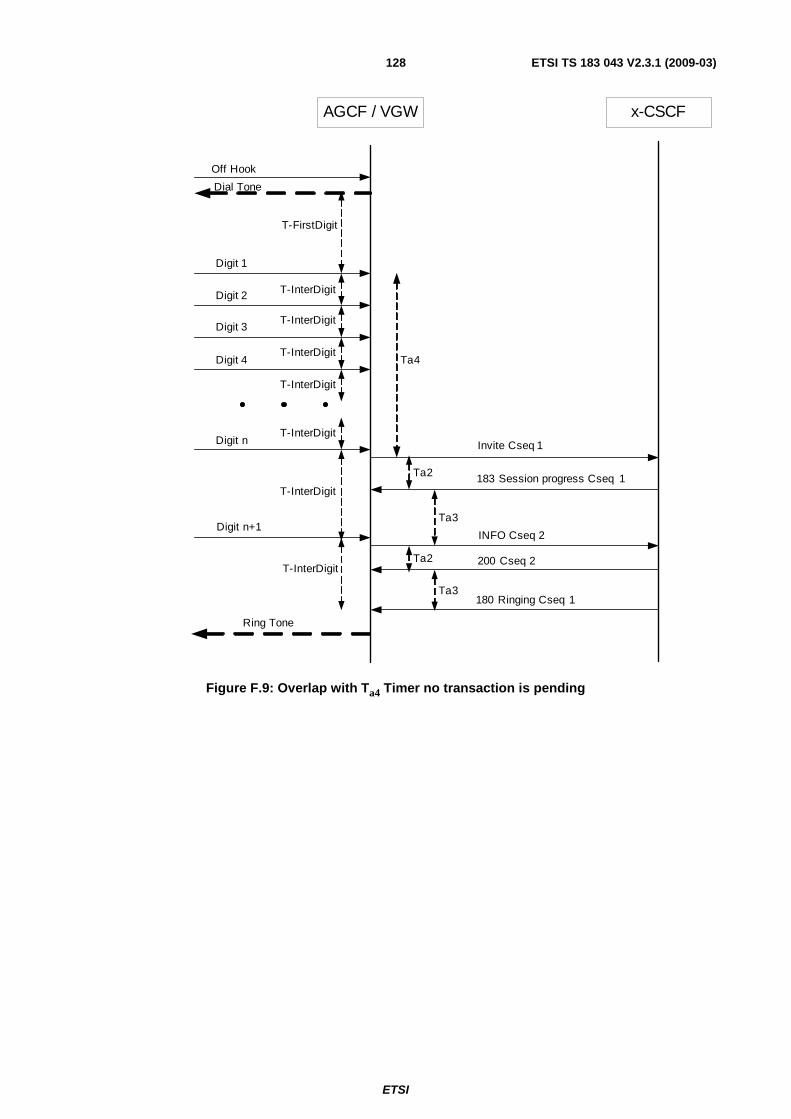
ETSI
ETSI TS 183 043 V2.3.1 (2009-03) 128
AGCF / VGW x-CSCF
Off Hook
T-FirstDigit
T-InterDigit
T-InterDigit
T-InterDigit
T-InterDigit
T-InterDigit
T-InterDigit
T-InterDigit
Ta4
Ta2
Ta2
Ta3
Ta3
Digit 1
Digit 2
Digit 3
Digit 4
Digit n
Digit n+1
Dial Tone
Ring Tone
Invite Cseq 1
183 Session progress Cseq 1
INFO Cseq 2
200 Cseq 2
180 Ringing Cseq 1
Figure F.9: Overlap with Ta4 Timer no transaction is pending

ETSI
ETSI TS 183 043 V2.3.1 (2009-03) 129
Option b) Overlap with Digit Map
AGCF/VGW x-CSCF
INVITE Cseq 1
180 Ringing Cseq 1
INFO Cseq 2
200 Cseq 2
Digit map matched
183 Session Progress Cseq 1
INFO Cseq 3
200 Cseq 3
Ring Tone
Off Hook
Digit 1
Digit 2
Digit 3
Digit n+1
Digit n
. . .
Digit n+2
Figure F.10: Overlap with digit map

ETSI
ETSI TS 183 043 V2.3.1 (2009-03) 130
Option c) Overlap with Digit Map and Ta4 Timer
AGCF/VGW x-CSCF
INVITE Cseq 1
180 Ringing Cseq 1
INFO Cseq 2
200 Cseq 2
Digit map matched
Stop Ta4
Ta4
INFO Cseq 3
200 Cseq 3
183 Session Progress Cseq 1
Ring Tone
Off Hook
Digit 1
Digit 2
Digit 3
Digit n
Digit 4
. . .
Digit n+1
Digit n+2
Figure F.11: Overlap with digit map and Ta4 timer digit map matched before Ta4 expiry

ETSI
ETSI TS 183 043 V2.3.1 (2009-03) 131
AGCF/VGW x-CSCF
INVITE Cseq 1
183 Session Progress Cseq 1
Digit map matched
Ta4
INFO Cseq 2
200 Cseq 2
180 Ringing Cseq 1
Ring Tone
Digit 1
Digit 2
Digit 3
Digit n
Digit 4
. . .
Digit n+1
Digit n+2
Off Hook
Figure F.12: Overlap with digit map and Ta4 timer digit map matched after Ta4 expiry

ETSI
ETSI TS 183 043 V2.3.1 (2009-03) 132
AGCF/VGW x-CSCF
Off Hook
INFO Cseq 2
Digit 1
Ta4
Digit 2
Digit 3
180 Ringing Cseq 1Ring Tone
Digit n
Digit 4
. . .
INVITE Cseq 1
183 Session Progress Cseq 1
Figure F.13: Overlap with Ta4 Timer - using the option to send the first INVITE at the off-hook event
F.3.2 Actions at the terminating VGW/AGCF No action with regard to overlap is needed.
DDI is out of scope of the present document.
F.3.3 Procedures at the overlap signalling AS (Optional) With receiving the initial INVITE the AS shall query the attached routing HSS or database to find the destination.
In case of an indication that more digits are needed the AS creates an early dialog by sending a 183 (Session Progress) response. The AS shall also start a T-InterDigit timer (typically 10 s to15 s) If the T-InterDigit timer expires then the call shall be released by the AS.
When additional address information is received within SIP INFO Requests, the AS SHALL add them to the previously received digits, and use them for HSS/database routing queries in order to being able to forward the call.
When enough address information has been collected to forward the call to the appropriate destination, the AS SHALL create a SIP INVITE request, which contains all the received address digits, and forward it towards the destination.
In cases where it is identified that the call shall be forwarded to networks not supporting overlap in-dialog signalling, the AS shall perform en-bloc conversion. If the minimum number of digits required for routing the call have been received, the AS shall start a short timer Ta1 (typically 4 s to 6 s) and wait for subsequent SIP INFO Requests carrying additional request information. When the Ta1 timer expires, the AS SHALL create a SIP INVITE request, which contains all the received address digits, and forward it towards the destination.
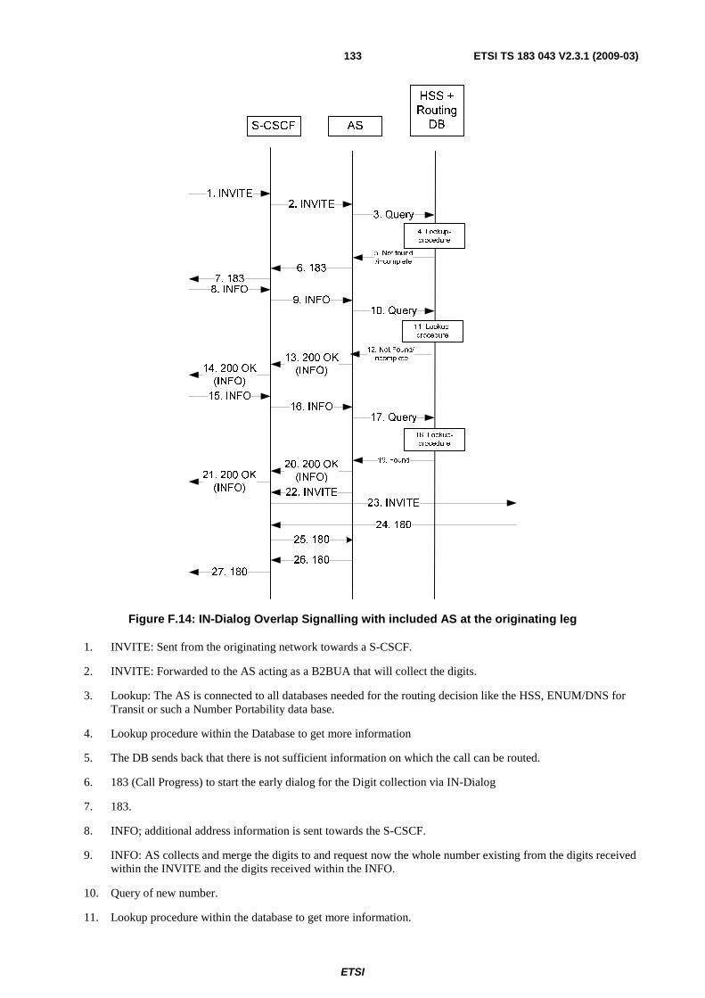
ETSI
ETSI TS 183 043 V2.3.1 (2009-03) 133
1. INVITE
5. Not found
/incomplete
12. Not Found/
Incomplete
S-CSCF AS
HSS +
Routing
DB
23. INVITE
8. INFO
24. 180
4. Lookup-
procedure
2. INVITE 3. Query
6. 1837. 183
9. INFO 10. Query
11. Lookup-
procedure
13. 200 OK
(INFO)14. 200 OK
(INFO)
19. Found
15. INFO 16. INFO
17. Query
18. Lookup-
procedure
20. 200 OK
(INFO)21. 200 OK
(INFO) 22. INVITE
25. 180
26. 18027. 180
Figure F.14: IN-Dialog Overlap Signalling with included AS at the originating leg
1. INVITE: Sent from the originating network towards a S-CSCF.
2. INVITE: Forwarded to the AS acting as a B2BUA that will collect the digits.
3. Lookup: The AS is connected to all databases needed for the routing decision like the HSS, ENUM/DNS for Transit or such a Number Portability data base.
4. Lookup procedure within the Database to get more information
5. The DB sends back that there is not sufficient information on which the call can be routed.
6. 183 (Call Progress) to start the early dialog for the Digit collection via IN-Dialog
7. 183.
8. INFO; additional address information is sent towards the S-CSCF.
9. INFO: AS collects and merge the digits to and request now the whole number existing from the digits received within the INVITE and the digits received within the INFO.
10. Query of new number.
11. Lookup procedure within the database to get more information.

ETSI
ETSI TS 183 043 V2.3.1 (2009-03) 134
12. The DB sends back that there is not sufficient information on which the call can be routed.
13. Send a 200 OK (INFO) back to that the digits are received.
14. 200 OK (INFO).
15. INFO; additional address information is sent towards the S-CSCF.
16. INFO: AS collects and merge the digits to and request now the whole number existing from the digits received within the INVITE and the digits received within the INFO.
17. Query of new number.
18. Lookup procedure within the database to get more information.
19. The DB sends back that there are sufficient digits received.
20. Send a 200 OK (INFO) back to that the digits are received.
21. 200 OK (INFO).
22. INVITE will be now forwarded back to the S-CSCF with the complete number/IP address of the terminating P-CSCF.
23. INVITE sent toward the terminating network.
24. 180 (Ringing)received from the terminating network.
25. 180 (Ringing) S-CSCF - AS.
26. 180 (Ringing) AS - S-CSCF.
27. 180 (Ringing) S-CSCF- towards originating network.
F.3.4 Overlap digit message body
F.3.4.1 Scope
This clause defines a message body that shall be used for sending additional digits, which have not previously been sent, in SIP INFO messages when the in-dialog method is used for overlap dialling.
The support of this message body is a network option.
NOTE: The contents of clause F.3.4 will be inherited in the Release 8 version of TS 129 163 [i.4], annex G. As a consequence clause F.3.4 will be removed in the NGN Release 3 document which will in general refer to 3GPP Release 8 specifications.
F.3.4.2 MIME type
The message body defined in the present annex is registered at IANA as "application/x-session-info" MIME type.
If the message body is embedded in SIP INFO messages, the Content-Type header shall be set to "application/x-session-info" and the Content-Disposition header shall be set to "signal" with the handling parameter set to "optional".
F.3.4.3 ABNF x-session-info = SubsequentDigit SubsequentDigit = "SubsequentDigit" HCOLON phonedigits phonedigits = 1*(HEXDIG / "*" / "#") HEXDIG = DIGIT / "A" / "B" / "C" / "D" / "E" / "F"

ETSI
ETSI TS 183 043 V2.3.1 (2009-03) 135
F.4 Timers Table F.1: Timers for interworking
Symbol Time-out value Cause for initiation Normal termination At expiry
T-FirstDigit 1 s to 99 s (default=60 s)
Upon start of dial tone injection
On receipt of the first dialed digit
Release Call
T-InterDigit 1 s to 15 s (default=10 s)
Upon receipt of a new address message
Upon receipt of subsequent address message or 180 Ringing or 183 Session Progress with P-Early Media header authorizing early media
a) Disable Digit Receiver; b) if Ta3 is not running then Release Call
Ta1 4 s to 6 s (default of 4 s) (see note 1)
When last address information is received and the minimum number of digits required for routing the call have been received.
At the receipt of fresh address information.
Send INVITE
Ta2 (Multiple Invite)
10 s to 15 s (see notes 2 and 4)
When INVITE is sent. On reception of 180 Ringing , or 183 Session Progress, or 404 Not Found or 484 Address Incomplete for an INVITE transaction for which Ta2is running, or 200 OK (INVITE).
Release Call
Ta2 (In-Dialog)
10 s to 15 s (see notes 2 and 4)
When INVITE is sent or when INFO is sent.
On reception of 180 Ringing , or 183 Session Progress, or 404 Not Found or 484 Address Incomplete for an INVITE transaction for which Ta2 is running, or 200 OK (INVITE) or 200 OK (INFO).
Release Call
Ta3 (Multiple invite)
4 s to 20 s (default of 15 s) (see note 3)
On receipt of 404 Not Found or 484 Address Incomplete if there are no other pending INVITE transactions for the corresponding call.
At the receipt of fresh address information
Release call
Ta3 (In-Dialog)
4 s to20 s (default of 15 s) (see note 3)
On receipt of 404 Not Found or 484 Address Incomplete if there are no other pending INVITE transactions for the corresponding call. On receipt of 200 OK (INFO), or 183 Session Progress without early media authorization.
At the receipt of fresh address information or 180 Ringing or 183 with P-Early-Media header authorizing early media or 200 OK (INVITE)
Release call
Ta4 0,5 s to -4 s
On receipt of the initial address information..
At expiry Send INVITE
NOTE 1: This timer is used in clause F.1 when overlap signalling is received from access line and converted to en-block signalling at the AGCF/VGW.
NOTE 2: This timer is used in clauses F.2 and F.3 to wait for an 404/484 response. In addition clause F.3 uses this timer for:
a) to wait for an 183 response to an INVITE; b) to wait for a 200 OK (INFO) response. NOTE 3: This timer is known as the "SIP dialog protection timer". This timer is only used where the AGCF/VGW is
configured to send INVITE before end of address signalling is determined. The Ta3 timer shall be greater than the T-InterDigit timer.
NOTE 4: The value of timer Ta2 may vary beyond these limits, e.g. as a result of called party number analysis.

ETSI
ETSI TS 183 043 V2.3.1 (2009-03) 136
Annex G (informative): Digit collection in MRF after receipt of flash-hook in the tight coupling model
G.1 Introduction In the case where the tight coupling model is used for flash-hook invoked services, this annex describes the optional use of the MRF for collection of dialled digits and provision of dial tone.
G.2 Management of dial tone and digit collection in the MRF
On detection of a flash-hook the Feature Manager of AGCF/VGW performs the following actions:
• Initiate the active call to be placed on hold by sending of re-INVITE to AS and wait for 200 OK from the AS. The AS may put the B-party on hold and may also arrange for an announcement to be played to the held party via an MRF as described in annex C for the specific services.
• Feature Manager may request the SIP UA to create a new dialogue and to send an INVITE (flash) including an SDP offer for a voice call to the AS.
On reception of INVITE from AGCF/VGW indicating flash-hook the AS may invoke the following actions:
• Create a new dialogue to MRF to arrange the bearers to connect the MRF and the caller having triggered the flash.
• Trigger the MRF to provide dial tone to the caller and to start inband collection of dialled digits.
The MRF now starts to play the dial tone and is waiting for digits to be dialled by the caller. Collected digits are reported to the AS which has to interpret the digits dependent on the current service configuration as e.g. dialled terminating subscriber number in a Three Party scenario or as a switching order command e.g. during Call Toggle Service.
It is the responsibility of the AS to close the dialogue to the MRF after finished evaluation of reported digits.

ETSI
ETSI TS 183 043 V2.3.1 (2009-03) 137
Annex H (informative): Bibliography
• ETSI ES 282 007: "Telecommunications and Internet converged Services and Protocols for Advanced Networking (TISPAN); IP Multimedia Subsystem (IMS); Functional architecture".

ETSI
ETSI TS 183 043 V2.3.1 (2009-03) 138
Annex I (informative): Change history
Date WG Doc. CR Rev CAT Title / Comment Current Version
New Version
01-05-06 Publication of v1.1.1 07-03-08 16bTD512 003 F Alignment with Stage 2 2.0.0 2.1.0 07-03-08 WG3-02-016r
2 in 16bTD264 004 F Support of RTTI 2.0.0 2.1.0
07-03-08 WG3-02-017r2 in 16bTD264
005 F Dial tone management 2.0.0 2.1.0
07-03-08 WG3-02-034r2 in 16bTD264
006 B P-Access-Network-Info 2.0.0 2.1.0
07-03-08 16bTD301r4 007 1 F AOC for POTS Line Metering 2.0.0 2.1.0 07-03-08 008 Withdrawn because replaced by CR 007r1 2.0.0 2.1.0 07-03-08 WG3-02-041r
2 in 16bTD264 009 F P-Earlymedia header 2.0.0 2.1.0
07-03-08 16bTD267r3 010 3 F Population of P-Asserted-Id 2.0.0 2.1.0 07-03-08 16bTD268r1 011 F Switching order commands examples 2.0.0 2.1.0 07-03-08 16bTD269r1 012 F Actions performed by AGCF 2.0.0 2.1.0 07-03-08 16bTD275r3 013 3 C Call Initiation 2.0.0 2.1.0 07-03-08 16bTD270r2 014 F Handling of suspend timer 2.0.0 2.1.0 30-05-08 17bTD197r2 015 B Profile delivery 2.1.0 2.1.1 30-05-08 17bTD218r2 016 F Pulse Metering - new section C.16 in TS 183 043 2.1.0 2.1.1 30-05-08 17bTD234r1 018 D Call Waiting 2.1.0 2.1.1 30-05-08 17bTD235r1 019 D MCID 2.1.0 2.1.1 30-05-08 17bTD236r1 020 F CLIP CLIR 2.1.0 2.1.1 30-05-08 17bTD238r1 021 D WI03134 Call Forwarding 2.1.0 2.1.1 30-05-08 17bTD239r1 022 F WI03134 Automatic Call Return 2.1.0 2.1.1 30-05-08 17bTD240r1 023 F ACR 2.1.0 2.1.1 30-05-08 17bTD241r1 024 F AGCF Charging 2.1.0 2.1.1 30-05-08 17bTD242r1 025 F Session Progress 2.1.0 2.1.1 30-05-08 17bTD257r2 026 F 3PTY 2.1.0 2.1.1 17-06-08 Clean-up and addition of Change History annex by ETSI Secretariat 2.1.1 2.1.2 02-07-08 18WTD202r1
WG3-03-021r4
027 1 F AGCF behaviour when the user does not dial any digit 2.1.2 2.1.3
02-07-08 18WTD132 WG3-03-022r
1 028 F Separate the loose and tight coupled options in the 3PTY service 2.1.2 2.1.3
02-07-08 18WTD132 WG-03-023r1
029 F Separate the loose and tight coupling for CW 2.1.2 2.1.3
02-07-08 WG3-03-016r3
030 F Advice of Charge (Annex C.2) 2.1.2 2.1.3
02-07-08 WG3-03-017r3 revised in
xxx 031 1 F AOC-Extended XML schema 2.1.2 2.1.3
02-07-08 18WTD132 WG3-03-024r
1 032 C Additional flexibility of the AGCF to support different message servers 2.1.2 2.1.3
02-07-08 18WTD132 WG3-03-027r
1 033 F Correction to the use of privacy field in ACR 2.1.2 2.1.3
02-07-08 18WTD122r1 034 1 C Overlap in-dialog method 2.1.2 2.1.3 02-07-08 18WTD202r1
WG3-03-033r1
035 D Harmonization of global and group registration 2.1.2 2.1.3
02-07-08 18WTD202r1 WG3-03-034r
1 036 F Addition of figures for 3PTY 2.1.2 2.1.3
02-07-08 18WTD202r1 WG3-03-035r
1 037 B Wildcarded Identities 2.1.2 2.1.3
02-07-08 18WTD123r3 038 C Additional procedures to align the loose coupled procedures with the MCID simulation service
2.1.2 2.1.3
02-07-08 18WTD192r1 039 D Profile Delivery Editorial Corrections 2.1.2 2.1.3 02-07-08 18WTD193r2 040 B Profile Item HOLD 2.1.2 2.1.3 02-07-08 18WTD194r2 041 B Profile Item Toggle 2.1.2 2.1.3 02-07-08 18WTD195r2 042 B Profile Item 3PTY 2.1.2 2.1.3 02-07-08 18WTD196r2 043 B Profile Item CW 2.1.2 2.1.3 02-07-08 18WTD253r1 044 B Profile Delivery Optional 2.1.2 2.1.3 02-07-08 18WTD200r2 045 F CLIP / CLIR section C.5 2.1.2 2.1.3 02-07-08 18WTD218r1 046 F Multiple terminations per public user identity 2.1.2 2.1.3 02-07-08 18WTD246r1 047 F Alignment between Clause 7 and Annex C 2.1.2 2.1.3 02-07-08 18WTD248r1 048 F Alignment between Annex B and C 2.1.2 2.1.3 26-09-08 18bTD267r1 049 C Overlap in-dialog method 2.1.3 2.1.4 26-09-08 18bTD262r1 050 F Improving the structure of TS 183 043 2.1.3 2.1.4 26-09-08 18bTD254r3 051 B Profile Delivery XML 2.1.3 2.1.4 26-09-08 18bTD278r3 053 C VGW Procedures for tightly coupled and loosely coupled procedures 2.1.3 2.1.4 26-09-08 18bTD280r2 052 C Call Waiting procedures 2.1.3 2.1.4

ETSI
ETSI TS 183 043 V2.3.1 (2009-03) 139
Date WG Doc. CR Rev CAT Title / Comment Current Version
New Version
05-11-08 19WTD202r1 054 F Correction of the Name of P-Asserted_identity Header 2.1.3 2.1.5 05-11-08 19WTD129r1 055 F P-Preferred-Identity and P-Asserted-Identity headers 2.1.3 2.1.5 05-11-08 19WTD138r1 056 F VGW protocol role 2.1.3 2.1.5 05-11-08 19WTD180r1 057 F AS behaviour 2.1.3 2.1.5 05-11-08 19WTD107r2 058 2 F Corrections to VGW 2.1.3 2.1.5 05-11-08 19WTD124r2 059 F Annex A - Profile Delivery XML 2.1.3 2.1.5 05-11-08 19WTD200r2 060 1 F Flash Hook procedures 2.1.3 2.1.5 05-11-08 19WTD127r2 061 F CLIP/CLIR -section C.5.3 2.1.3 2.1.5 05-11-08 19WTD131r1 062 F SS Configuration 2.1.3 2.1.5 05-11-08 19WTD166r2 063 F HOLD procedures in Tight coupling mode 2.1.3 2.1.5 05-11-08 19WTD197r2 064 1 F Call waiting Procedures 2.1.3 2.1.5 05-11-08 19WTD201r1 065 F 3PTY/CONF Procedures 2.1.3 2.1.5 05-11-08 19WTD139r2 066 F SDP Procedures 2.1.3 2.1.5 05-11-08 19WTD212r1 067 F OVERLAP AS procedure 2.1.3 2.1.5 05-11-08 19WTD126r1 068 F Overlap Signalling Ta3 timer 2.1.3 2.1.5 05-11-08 19WTD128r1 069 F Overlap sending 2.1.3 2.1.5 05-11-08 19WTD132r1 070 F Correction of Call Flow for In-Dialog Method, INVITE without digits at off-hook 2.1.3 2.1.5 05-11-08 19WTD206r4 071 2 F Correction of Call Flow for In-Dialog Method, INVITE without digits at off-hook 2.1.3 2.1.5 05-11-08 19WTD160r1 072 Backward Compatibility of Tight Coupling Procedures 2.1.3 2.1.5 05-11-08 19WTD125r2 073 1 F Annex E - Extended AOC XML schema naming 2.1.3 2.1.5
05-11-08 19WTD170r3 074 F General Explanation of loose and tight coupling model - NOT IMPLEMENTED in 2.1.5
2.1.3 2.1.5
05-11-08 19WTD163r4 075 F Flash hook handling in Tight coupling model 2.1.3 2.1.5 13-11-08 CRs 049 to 075 TB approved and clean-up by ETSI Secretariat 2.1.5 2.2.0 24-11-08 19bTD210 054 1 F Correction of the Name of P-Asserted_identity Header 2.2.0 2.2.1 24-22-08 Correction implementation of CR055 2.2.0 2.2.1
05-11-08 19WTD170r3 074 F General Explanation of loose and tight coupling model - Already TB approved at TISPAN#19 but not implemented
2.2.1 2.2.2
26-11-08 19bTD104r2 076 F MESSAGE correlation 2.2.1 2.2.2 26-11-08 19bTD151r1 077 F Changes on timer section 2.2.1 2.2.2 26-11-08 19bTD095r2 078 1 B Re-ringing for loose coupled 2.2.1 2.2.2 26-11-08 19bTD110r3 080 2 F Registration of MIME type with IANA 2.2.1 2.2.2 26-11-08 19bTD216r5 081 4 F Call Waiting procedures 2.2.1 2.2.2 26-11-08 19bTD170r1 082 F Correction to In Dialog Method 2.2.1 2.2.2 26-11-08 19bTD150r1 083 F Correction of Call Flow for In-Dialog Method - sequence numbering 2.2.1 2.2.2 26-11-08 19bTD149r1 084 B Message body to transfer digits In-Dialog 2.2.1 2.2.2 26-11-08 19bTD232r2 085 F Clarification and editorial changes to WI3134 V2.2.1 2.2.1 2.2.2 09-12-08 19bTD241r1 086 F Re-ringing 2.2.2 2.2.3
Publication 2.2.3 2.3.1

ETSI
ETSI TS 183 043 V2.3.1 (2009-03) 140
History
Document history
V1.1.1 May 2006 Publication
V2.3.1 March 2009 Publication