TS 138 401 - V15.2.0 - 5G; NG-RAN; Architecture ... · ETSI 3GPP TS 38.401 version 15.2.0 Release...
40
ETSI TS 138 401 V15.2.0 (2018-07) 5G; NG-RAN; Architecture description (3GPP TS 38.401 version 15.2.0 Release 15) TECHNICAL SPECIFICATION
Transcript of TS 138 401 - V15.2.0 - 5G; NG-RAN; Architecture ... · ETSI 3GPP TS 38.401 version 15.2.0 Release...

ETSI TS 138 401 V15.2.0 (2018-07)
5G; NG-RAN;
Architecture description (3GPP TS 38.401 version 15.2.0 Release 15)
TECHNICAL SPECIFICATION

ETSI
ETSI TS 138 401 V15.2.0 (2018-07)13GPP TS 38.401 version 15.2.0 Release 15
Reference DTS/TSGR-0338401vf20
Keywords 5G
ETSI
650 Route des Lucioles F-06921 Sophia Antipolis Cedex - FRANCE
Tel.: +33 4 92 94 42 00 Fax: +33 4 93 65 47 16
Siret N° 348 623 562 00017 - NAF 742 C
Association à but non lucratif enregistrée à la Sous-Préfecture de Grasse (06) N° 7803/88
Important notice
The present document can be downloaded from: http://www.etsi.org/standards-search
The present document may be made available in electronic versions and/or in print. The content of any electronic and/or print versions of the present document shall not be modified without the prior written authorization of ETSI. In case of any
existing or perceived difference in contents between such versions and/or in print, the only prevailing document is the print of the Portable Document Format (PDF) version kept on a specific network drive within ETSI Secretariat.
Users of the present document should be aware that the document may be subject to revision or change of status. Information on the current status of this and other ETSI documents is available at
https://portal.etsi.org/TB/ETSIDeliverableStatus.aspx
If you find errors in the present document, please send your comment to one of the following services: https://portal.etsi.org/People/CommiteeSupportStaff.aspx
Copyright Notification
No part may be reproduced or utilized in any form or by any means, electronic or mechanical, including photocopying and microfilm except as authorized by written permission of ETSI.
The content of the PDF version shall not be modified without the written authorization of ETSI. The copyright and the foregoing restriction extend to reproduction in all media.
© ETSI 2018.
All rights reserved.
DECTTM, PLUGTESTSTM, UMTSTM and the ETSI logo are trademarks of ETSI registered for the benefit of its Members. 3GPPTM and LTETM are trademarks of ETSI registered for the benefit of its Members and
of the 3GPP Organizational Partners. oneM2M logo is protected for the benefit of its Members.
GSM® and the GSM logo are trademarks registered and owned by the GSM Association.

ETSI
ETSI TS 138 401 V15.2.0 (2018-07)23GPP TS 38.401 version 15.2.0 Release 15
Intellectual Property Rights Essential patents
IPRs essential or potentially essential to normative deliverables may have been declared to ETSI. The information pertaining to these essential IPRs, if any, is publicly available for ETSI members and non-members, and can be found in ETSI SR 000 314: "Intellectual Property Rights (IPRs); Essential, or potentially Essential, IPRs notified to ETSI in respect of ETSI standards", which is available from the ETSI Secretariat. Latest updates are available on the ETSI Web server (https://ipr.etsi.org/).
Pursuant to the ETSI IPR Policy, no investigation, including IPR searches, has been carried out by ETSI. No guarantee can be given as to the existence of other IPRs not referenced in ETSI SR 000 314 (or the updates on the ETSI Web server) which are, or may be, or may become, essential to the present document.
Trademarks
The present document may include trademarks and/or tradenames which are asserted and/or registered by their owners. ETSI claims no ownership of these except for any which are indicated as being the property of ETSI, and conveys no right to use or reproduce any trademark and/or tradename. Mention of those trademarks in the present document does not constitute an endorsement by ETSI of products, services or organizations associated with those trademarks.
Foreword This Technical Specification (TS) has been produced by ETSI 3rd Generation Partnership Project (3GPP).
The present document may refer to technical specifications or reports using their 3GPP identities, UMTS identities or GSM identities. These should be interpreted as being references to the corresponding ETSI deliverables.
The cross reference between GSM, UMTS, 3GPP and ETSI identities can be found under http://webapp.etsi.org/key/queryform.asp.
Modal verbs terminology In the present document "shall", "shall not", "should", "should not", "may", "need not", "will", "will not", "can" and "cannot" are to be interpreted as described in clause 3.2 of the ETSI Drafting Rules (Verbal forms for the expression of provisions).
"must" and "must not" are NOT allowed in ETSI deliverables except when used in direct citation.
ETSI
ETSI TS 138 401 V15.2.0 (2018-07)33GPP TS 38.401 version 15.2.0 Release 15
Contents Intellectual Property Rights ................................................................................................................................ 2
Foreword ............................................................................................................................................................. 2
Modal verbs terminology .................................................................................................................................... 2
Foreword ............................................................................................................................................................. 5
1 Scope ........................................................................................................................................................ 6
2 References ................................................................................................................................................ 6
3 Definitions and abbreviations ................................................................................................................... 6
3.1 Definitions .......................................................................................................................................................... 6
3.2 Abbreviations ..................................................................................................................................................... 7
4 General principles .................................................................................................................................... 8
5 General architecture ................................................................................................................................. 8
5.1 General ............................................................................................................................................................... 8
5.2 User plane ........................................................................................................................................................... 8
5.3 Control plane ...................................................................................................................................................... 9
6 NG-RAN architecture............................................................................................................................. 10
6.1 Overview .......................................................................................................................................................... 10
6.1.1 Overall Architecture of NG-RAN ............................................................................................................... 10
6.1.2 Overall architecture for separation of gNB-CU-CP and gNB-CU-UP ....................................................... 11
6.2 NG-RAN identifiers ......................................................................................................................................... 11
6.2.1 Principle of handling Application Protocol Identities ................................................................................. 11
6.2.2 gNB-DU ID ................................................................................................................................................ 13
6.3 Transport addresses .......................................................................................................................................... 13
6.4 UE associations in NG-RAN Node .................................................................................................................. 13
7 NG-RAN functions description .............................................................................................................. 14
7.0 General ............................................................................................................................................................. 14
7.1 Void .................................................................................................................................................................. 14
8 Overall procedures in gNB-CU/gNB-DU Architecture ......................................................................... 14
8.1 UE Initial Access .............................................................................................................................................. 14
8.2 Intra-gNB-CU Mobility .................................................................................................................................... 16
8.2.1 Intra-NR Mobility ....................................................................................................................................... 16
8.2.1.1 Inter-gNB-DU Mobility ........................................................................................................................ 16
8.2.1.2 Intra-gNB-DU handover ....................................................................................................................... 17
8.2.2 EN-DC Mobility ......................................................................................................................................... 17
8.2.2.1 Inter-gNB-DU Mobility using MCG SRB ............................................................................................ 17
8.2.2.2 Inter-gNB-DU Mobility using SCG SRB ............................................................................................. 19
8.3 Mechanism of centralized retransmission of lost PDUs ................................................................................... 19
8.3.1 Centralized Retransmission in Intra gNB-CU Cases .................................................................................. 19
8.4 Multi-Connectivity operation ........................................................................................................................... 20
8.4.1 Secondary Node Addition ........................................................................................................................... 20
8.4.1.1 EN-DC .................................................................................................................................................. 20
8.4.2 Secondary Node Release (MN/SN initiated) .............................................................................................. 21
8.4.2.1 EN-DC .................................................................................................................................................. 21
8.5 F1 Startup and cells activation ......................................................................................................................... 22
8.6 RRC state transition.......................................................................................................................................... 23
8.6.1 RRC connected to RRC inactive................................................................................................................. 23
8.6.2 RRC inactive to other states ........................................................................................................................ 23
8.7 RRC connection reestablishment ..................................................................................................................... 25
8.8 Multiple TNLAs for F1-C ................................................................................................................................ 26
8.9 Overall procedures involving E1 and F1 .......................................................................................................... 27
8.9.1 UE Initial Access ........................................................................................................................................ 27
8.9.2 Bearer context setup over F1-U .................................................................................................................. 28
8.9.3 Bearer context release over F1-U ............................................................................................................... 29
ETSI
ETSI TS 138 401 V15.2.0 (2018-07)43GPP TS 38.401 version 15.2.0 Release 15
8.9.3.1 gNB-CU-CP initiated bearer context release ........................................................................................ 29
8.9.3.2 gNB-CU-UP initiated bearer context release ........................................................................................ 29
8.9.4 Inter-gNB handover involving gNB-CU-UP change .................................................................................. 30
8.9.5 Change of gNB-CU-UP .............................................................................................................................. 31
8.9.6 RRC State transition ................................................................................................................................... 32
8.9.6.1 RRC Connected to RRC Inactive .......................................................................................................... 32
8.9.6.2 RRC Inactive to other states .................................................................................................................. 33
9 Synchronization ...................................................................................................................................... 35
9.1 gNB Synchronization ....................................................................................................................................... 35
10 NG-RAN interfaces ................................................................................................................................ 35
10.1 NG interface ..................................................................................................................................................... 35
10.2 Xn interface ...................................................................................................................................................... 35
10.3 F1 interface ....................................................................................................................................................... 35
10.4 E1 interface ...................................................................................................................................................... 36
Annex A (informative): Deployment scenarios of gNB/en-gNB ......................................................... 37
Annex B (informative): Change History .............................................................................................. 38
History .............................................................................................................................................................. 39
ETSI
ETSI TS 138 401 V15.2.0 (2018-07)53GPP TS 38.401 version 15.2.0 Release 15
Foreword This Technical Specification has been produced by the 3rd Generation Partnership Project (3GPP).
The contents of the present document are subject to continuing work within the TSG and may change following formal TSG approval. Should the TSG modify the contents of the present document, it will be re-released by the TSG with an identifying change of release date and an increase in version number as follows:
Version x.y.z
where:
x the first digit:
1 presented to TSG for information;
2 presented to TSG for approval;
3 or greater indicates TSG approved document under change control.
y the second digit is incremented for all changes of substance, i.e. technical enhancements, corrections, updates, etc.
z the third digit is incremented when editorial only changes have been incorporated in the document.
ETSI
ETSI TS 138 401 V15.2.0 (2018-07)63GPP TS 38.401 version 15.2.0 Release 15
1 Scope The present document describes the overall architecture of the NG-RAN, including interfaces NG, Xn and F1 interfaces and their interaction with the radio interface.
2 References The following documents contain provisions which, through reference in this text, constitute provisions of the present document.
- References are either specific (identified by date of publication, edition number, version number, etc.) or non-specific.
- For a specific reference, subsequent revisions do not apply.
- For a non-specific reference, the latest version applies. In the case of a reference to a 3GPP document (including a GSM document), a non-specific reference implicitly refers to the latest version of that document in the same Release as the present document.
[1] 3GPP TR 21.905: "Vocabulary for 3GPP Specifications".
[2] 3GPP TS 38.300: "NR; Overall description; Stage-2".
[3] 3GPP TS 23.501: "System Architecture for the 5G System".
[4] 3GPP TS 38.473: "NG-RAN; F1 application protocol (F1AP)".
[5] 3GPP TS 38.414: "NG-RAN; NG data transport".
[6] 3GPP TS 38.424: "NG-RAN; Xn data transport".
[7] 3GPP TS 38.474: "NG-RAN; F1 data transport".
[8] ITU-T Recommendation G.823 (2000-03): "The control of jitter and wander within digital networks which are based on the 2048 kbit/s hierarchy".
[9] ITU-T Recommendation G.824 (2000-03): "The control of jitter and wander within digital networks which are based on the 1544 kbit/s hierarchy".
[10] ITU-T Recommendation G.825 (2001-08): "The control of jitter and wander within digital networks which are based on the synchronous digital hierarchy (SDH)".
[11] ITU-T Recommendation G.8261/Y.1361 (2008-04): "Timing and Synchronization aspects in Packet networks".
[12] 3GPP TS 37.340: "NR; Multi-connectivity; Overall description; Stage-2".
[13] 3GPP TS 33.501: "Security Architecture and Procedures for 5G System".
[14] 3GPP TS 38.410: "NG-RAN; NG general aspect and principles".
[15] 3GPP TS 38.420: "NG-RAN; Xn general aspects and principles"
[16] 3GPP TS 38.470: "NG-RAN; F1 general aspects and principles".
[17] 3GPP TS 38.460: "NG-RAN; E1 general aspects and principles".
3 Definitions and abbreviations
3.1 Definitions For the purposes of the present document, the terms and definitions given in TR 21.905 [1] and the following apply. A term defined in the present document takes precedence over the definition of the same term, if any, in TR 21.905 [1].

ETSI
ETSI TS 138 401 V15.2.0 (2018-07)73GPP TS 38.401 version 15.2.0 Release 15
en-gNB: as defined in TS 37.340 [12].
gNB: as defined in TS 38.300 [2].
gNB Central Unit (gNB-CU): a logical node hosting RRC, SDAP and PDCP protocols of the gNB or RRC and PDCP protocols of the en-gNB that controls the operation of one or more gNB-DUs. The gNB-CU terminates the F1 interface connected with the gNB-DU.
gNB Distributed Unit (gNB-DU): a logical node hosting RLC, MAC and PHY layers of the gNB or en-gNB, and its operation is partly controlled by gNB-CU. One gNB-DU supports one or multiple cells. One cell is supported by only one gNB-DU. The gNB-DU terminates the F1 interface connected with the gNB-CU.
gNB-CU-Control Plane (gNB-CU-CP): a logical node hosting the RRC and the control plane part of the PDCP protocol of the gNB-CU for an en-gNB or a gNB. The gNB-CU-CP terminates the E1 interface connected with the gNB-CU-UP and the F1-C interface connected with the gNB-DU.
gNB-CU-User Plane (gNB-CU-UP): a logical node hosting the user plane part of the PDCP protocol of the gNB-CU for an en-gNB, and the user plane part of the PDCP protocol and the SDAP protocol of the gNB-CU for a gNB. The gNB-CU-UP terminates the E1 interface connected with the gNB-CU-CP and the F1-U interface connected with the gNB-DU.
NG-RAN node: as defined in TS 38.300 [2].
PDU Session Resource: This term is used for specification of NG, Xn, and E1 interfaces. It denotes NG-RAN interface and radio resources provided to support a PDU Session.
3.2 Abbreviations For the purposes of the present document, the terms and definitions given in TR 21.905 [1] and the following apply. A term defined in the present document takes precedence over the definition of the same term, if any, in TR 21.905 [1].
5GC 5G Core Network AMF Access and Mobility Management Function AP Application Protocol AS Access Stratum CM Connection Management CMAS Commercial Mobile Alert Service ETWS Earthquake and Tsunami Warning System F1-U F1 User plane interface F1-C F1 Control plane interface F1AP F1 Application Protocol FDD Frequency Division Duplex GTP-U GPRS Tunnelling Protocol IP Internet Protocol NAS Non-Access Stratum O&M Operation and Maintenance PWS Public Warning System QoS Quality of Service RNL Radio Network Layer RRC Radio Resource Control SAP Service Access Point SCTP Stream Control Transmission Protocol SFN System Frame Number SM Session Management SMF Session Management Function TDD Time Division Duplex TDM Time Division Multiplexing TNL Transport Network Layer
ETSI
ETSI TS 138 401 V15.2.0 (2018-07)83GPP TS 38.401 version 15.2.0 Release 15
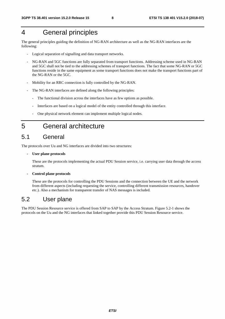
4 General principles The general principles guiding the definition of NG-RAN architecture as well as the NG-RAN interfaces are the following:
- Logical separation of signalling and data transport networks.
- NG-RAN and 5GC functions are fully separated from transport functions. Addressing scheme used in NG-RAN and 5GC shall not be tied to the addressing schemes of transport functions. The fact that some NG-RAN or 5GC functions reside in the same equipment as some transport functions does not make the transport functions part of the NG-RAN or the 5GC.
- Mobility for an RRC connection is fully controlled by the NG-RAN.
- The NG-RAN interfaces are defined along the following principles:
- The functional division across the interfaces have as few options as possible.
- Interfaces are based on a logical model of the entity controlled through this interface.
- One physical network element can implement multiple logical nodes.
5 General architecture
5.1 General The protocols over Uu and NG interfaces are divided into two structures:
- User plane protocols
These are the protocols implementing the actual PDU Session service, i.e. carrying user data through the access stratum.
- Control plane protocols
These are the protocols for controlling the PDU Sessions and the connection between the UE and the network from different aspects (including requesting the service, controlling different transmission resources, handover etc.). Also a mechanism for transparent transfer of NAS messages is included.
5.2 User plane The PDU Session Resource service is offered from SAP to SAP by the Access Stratum. Figure 5.2-1 shows the protocols on the Uu and the NG interfaces that linked together provide this PDU Session Resource service.

ETSI
ETSI TS 138 401 V15.2.0 (2018-07)93GPP TS 38.401 version 15.2.0 Release 15
(Uu) NG-RANUE 5GC
Access Stratum
Non-Access Stratum
Radio NG
Radio proto-cols(1)
Radioproto-cols(1)
NG protocols
(2)
NG proto cols
(2)
NOTE 1: The radio interface protocols are defined in 3GPP TS 38.2xx and TS 38.3xx. NOTE 2: The NG interface protocols are defined in 3GPP TS 38.41x.
Figure 5.2-1: NG and Uu user plane
5.3 Control plane Figure 5.3-1 shows the control plane (signalling) protocol stacks on NG and Uu interfaces.
NG-RANUE 5GCAccess Stratum
Non-Access Stratum
Radio(Uu)
NG
Radio proto-cols(1)
Radio proto-cols(1)
NGprotocols(2)
NGprotocols(2)
CM,SM CM,SM (3) (3)
NOTE 1: The radio interface protocols are defined in 3GPP TS 38.2xx and TS 38.3xx. NOTE 2: The protocol is defined in 3GPP TS 38.41x. (Description of NG interface). NOTE 3: CM, SM: This exemplifies a set of NAS control protocols between UE and 5GC. The evolution of the
protocol architecture for these protocols is outside the scope of the present document.
Figure 5.3-1: NG and Uu control plane
NOTE: Both the Radio protocols and the NG protocols contain a mechanism to transparently transfer NAS messages.
ETSI
ETSI TS 138 401 V15.2.0 (2018-07)103GPP TS 38.401 version 15.2.0 Release 15
6 NG-RAN architecture
6.1 Overview
6.1.1 Overall Architecture of NG-RAN
5GC
NG NG
Xn-C
NG-RAN
gNB
gNB-DU gNB-DU
gNB-CUgNB
F1F1
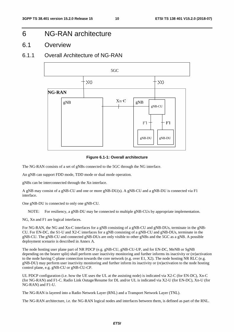
Figure 6.1-1: Overall architecture
The NG-RAN consists of a set of gNBs connected to the 5GC through the NG interface.
An gNB can support FDD mode, TDD mode or dual mode operation.
gNBs can be interconnected through the Xn interface.
A gNB may consist of a gNB-CU and one or more gNB-DU(s). A gNB-CU and a gNB-DU is connected via F1 interface.
One gNB-DU is connected to only one gNB-CU.
NOTE: For resiliency, a gNB-DU may be connected to multiple gNB-CUs by appropriate implementation.
NG, Xn and F1 are logical interfaces.
For NG-RAN, the NG and Xn-C interfaces for a gNB consisting of a gNB-CU and gNB-DUs, terminate in the gNB-CU. For EN-DC, the S1-U and X2-C interfaces for a gNB consisting of a gNB-CU and gNB-DUs, terminate in the gNB-CU. The gNB-CU and connected gNB-DUs are only visible to other gNBs and the 5GC as a gNB. A possible deployment scenario is described in Annex A.
The node hosting user plane part of NR PDCP (e.g. gNB-CU, gNB-CU-UP, and for EN-DC, MeNB or SgNB depending on the bearer split) shall perform user inactivity monitoring and further informs its inactivity or (re)activation to the node having C-plane connection towards the core network (e.g. over E1, X2). The node hosting NR RLC (e.g. gNB-DU) may perform user inactivity monitoring and further inform its inactivity or (re)activation to the node hosting control plane, e.g. gNB-CU or gNB-CU-CP.
UL PDCP configuration (i.e. how the UE uses the UL at the assisting node) is indicated via X2-C (for EN-DC), Xn-C (for NG-RAN) and F1-C. Radio Link Outage/Resume for DL and/or UL is indicated via X2-U (for EN-DC), Xn-U (for NG-RAN) and F1-U.
The NG-RAN is layered into a Radio Network Layer (RNL) and a Transport Network Layer (TNL).
The NG-RAN architecture, i.e. the NG-RAN logical nodes and interfaces between them, is defined as part of the RNL.

ETSI
ETSI TS 138 401 V15.2.0 (2018-07)113GPP TS 38.401 version 15.2.0 Release 15
For each NG-RAN interface (NG, Xn, F1) the related TNL protocol and the functionality are specified. The TNL provides services for user plane transport, signalling transport.
In NG-Flex configuration, each gNB is connected to all AMFs within an AMF Region. The AMF Region is defined in 3GPP TS 23.501 [3].
If security protection for control plane and user plane data on TNL of NG-RAN interfaces has to be supported, NDS/IP 3GPP TS 33.501 [13] shall be applied.
6.1.2 Overall architecture for separation of gNB-CU-CP and gNB-CU-UP
The overall architecture for separation of gNB-CU-CP and gNB-CU-UP is depicted in Figure 6.1.2-1.
E1
gNB-DU
gNB-CU-CP
F1-C F1-U
gNB
gNB-CU-UP
gNB-DU
Figure 6.1.2-1. Overall architecture for separation of gNB-CU-CP and gNB-CU-UP
- A gNB may consist of a gNB-CU-CP, multiple gNB-CU-UPs and multiple gNB-DUs;
- A gNB may consist of a gNB-CU-CP, multiple gNB-CU-UPs and multiple gNB-DUs;
- The gNB-CU-CP is connected to the gNB-DU through the F1-C interface;
- The gNB-CU-UP is connected to the gNB-DU through the F1-U interface;
- The gNB-CU-UP is connected to the gNB-CU-CP through the E1 interface;
- One gNB-DU is connected to only one gNB-CU-CP;
- One gNB-CU-UP is connected to only one gNB-CU-CP;
NOTE 1: For resiliency, a gNB-DU and/or a gNB-CU-UP may be connected to multiple gNB-CU-CPs by appropriate implementation.
- One gNB-DU can be connected to multiple gNB-CU-UPs under the control of the same gNB-CU-CP;
- One gNB-CU-UP can be connected to multiple DUs under the control of the same gNB-CU-CP;
NOTE 2: The connectivity between a gNB-CU-UP and a gNB-DU is established by the gNB-CU-CP using Bearer Context Management functions.
NOTE 3: The gNB-CU-CP selects the appropriate gNB-CU-UP(s) for the requested services for the UE.
NOTE 4: Data forwarding between gNB-CU-UPs during intra-gNB-CU-CP handover within a gNB may be supported by Xn-U.
6.2 NG-RAN identifiers
6.2.1 Principle of handling Application Protocol Identities
An Application Protocol Identity (AP ID) is allocated when a new UE-associated logical connection is created in either an NG-RAN node or an AMF. An AP ID shall uniquely identify a logical connection associated to a UE over the NG

ETSI
ETSI TS 138 401 V15.2.0 (2018-07)123GPP TS 38.401 version 15.2.0 Release 15
interface or Xn interface within a node (NG-RAN node or AMF) or over the F1 interface or over the E1 interface. Upon receipt of a message that has a new AP ID from the sending node, the receiving node shall store the AP ID of the sending node for the duration of the logical connection. The receiving node shall assign the AP ID to be used to identify the logical connection associated to the UE and include it as well as the previously received new AP ID from the sending node, in the first returned message to the sending node. In all subsequent messages to and from sending node, both AP IDs of sending node and receiving node shall be included.
The definitions of AP IDs as used on NG interface or Xn interface or F1 interface or E1 interface are shown below:
RAN UE NGAP ID:
A RAN UE NGAP ID shall be allocated so as to uniquely identify the UE over the NG interface within an gNB. When an AMF receives an RAN UE NGAP ID it shall store it for the duration of the UE-associated logical NG-connection for this UE. Once known to an AMF this is included in all UE associated NGAP signalling.
The RAN UE NGAP ID shall be unique within the logical NG-RAN node.
AMF UE NGAP ID:
An AMF UE NGAP ID shall be allocated so as to uniquely identify the UE over the NG interface within the AMF. When a NG-RAN node receives an AMF UE NGAP ID it shall store it for the duration of the UE-associated logical NG-connection for this UE. Once known to a NG-RAN node this ID is included in all UE associated NGAP signalling.
The AMF UE NGAP ID shall be unique within the AMF logical node.
Old NG-RAN node UE XnAP ID:
An Old NG-RAN node UE XnAP ID shall be allocated so as to uniquely identify the UE over the Xn interface within a source NG-RAN node. When a target NG-RAN node receives an Old NG-RAN node UE XnAP ID it shall store it for the duration of the UE-associated logical Xn-connection for this UE. Once known to a target NG-RAN node this ID is included in all UE associated XnAP signalling. The Old NG-RAN node UE XnAP ID shall be unique within the logical NG-RAN node.
New NG-RAN node UE XnAP ID:
A New NG-RAN node UE XnAP ID shall be allocated so as to uniquely identify the UE over the Xn interface within a target NG-RAN node. When a source NG-RAN node receives a New NG-RAN node UE XnAP ID it shall store it for the duration of the UE-associated logical Xn-connection for this UE. Once known to a source NG-RAN node this ID is included in all UE associated XnAP signalling. The New NG-RAN node UE XnAP ID shall be unique within the logical NG-RAN node.
M-NG-RAN node UE XnAP ID:
An M-NG-RAN node UE XnAP ID shall be allocated so as to uniquely identify the UE over the Xn interface within an M-NG-RAN node for dual connectivity. When an S-NG-RAN node receives an M-NG-RAN node UE XnAP ID it shall store it for the duration of the UE-associated logical Xn-connection for this UE. Once known to an S-NG-RAN node this ID is included in all UE associated XnAP signalling. The M-NG-RAN node UE XnAP ID shall be unique within the logical NG-RAN node.
S-NG-RAN node UE XnAP ID:
A S-NG-RAN node UE XnAP ID shall be allocated so as to uniquely identify the UE over the Xn interface within an S-NG-RAN node for dual connectivity. When an M-NG-RAN node receives a S-NG-RAN node UE XnAP ID it shall store it for the duration of the UE-associated logical Xn-connection for this UE. Once known to an M-NG-RAN node this ID is included in all UE associated XnAP signalling. The S-NG-RAN node UE XnAP ID shall be unique within the logical NG-RAN node.
gNB-CU UE F1AP ID:
A gNB-CU UE F1AP ID shall be allocated so as to uniquely identify the UE over the F1 interface within a gNB-CU. When a gNB-DU receives a gNB-CU UE F1AP ID it shall store it for the duration of the UE-associated logical F1-connection for this UE. The gNB-CU UE F1AP ID shall be unique within the gNB-CU logical node.
gNB-DU UE F1AP ID:
ETSI
ETSI TS 138 401 V15.2.0 (2018-07)133GPP TS 38.401 version 15.2.0 Release 15
A gNB-DU UE F1AP ID shall be allocated so as to uniquely identify the UE over the F1 interface within a gNB-DU. When a gNB-CU receives a gNB-DU UE F1AP ID it shall store it for the duration of the UE-associated logical F1-connection for this UE. The gNB-DU UE F1AP ID shall be unique within the gNB-DU logical node.
gNB-CU-CP UE E1AP ID:
A gNB-CU-CP UE E1AP ID shall be allocated so as to uniquely identify the UE over the E1 interface within a gNB-CU-CP. When a gNB-CU-UP receives a gNB-CU-CP UE E1AP ID it shall store it for the duration of the UE-associated logical E1-connection for this UE. The gNB-CU-CP UE E1AP ID shall be unique within the gNB-CU-CP logical node.
gNB-CU-UP UE E1AP ID:
A gNB-CU-UP UE E1AP ID shall be allocated so as to uniquely identify the UE over the E1 interface within a gNB-CU-UP. When a gNB-CU-CP receives a gNB-CU-UP UE E1AP ID it shall store it for the duration of the UE-associated logical E1-connection for this UE. The gNB-CU-UP UE E1AP ID shall be unique within the gNB-CU-UP logical node.
6.2.2 gNB-DU ID
The gNB-DU ID is configured at the gNB-DU and used to uniquely identify the gNB-DU at least within a gNB-CU. The gNB-DU provides its gNB-DU ID to the gNB-CU during the F1 Setup procedure. The gNB-DU ID is used only within F1AP procedures.
6.3 Transport addresses The transport layer address parameter is transported in the radio network application signalling procedures that result in establishment of transport bearer connections.
The transport layer address parameter shall not be interpreted in the radio network application protocols and reveal the addressing format used in the transport layer.
The formats of the transport layer addresses are further described in 3GPP TS 38.414 [5], 3GPP TS 38.424 [6] and 3GPP TS 38.474 [7].
6.4 UE associations in NG-RAN Node There are several types of UE associations needed in the NG-RAN node: the "NG-RAN node UE context" used to store all information needed for a UE and the associations between the UE and the logical NG and Xn connections used for NG/XnAP UE associated messages. An "NG-RAN node UE context" exists for a UE in CM_CONNECTED.
Definitions:
NG-RAN node UE context:
An NG-RAN node UE context is a block of information in an NG-RAN node associated to one UE. The block of information contains the necessary information required to maintain the NG-RAN services towards the active UE. An NG-RAN node UE context is established when the transition to RRC CONNECTED for a UE is completed or in the target NG-RAN node after completion of handover resource allocation during handover preparation, in which case at least UE state information, security information, UE capability information and the identities of the UE-associated logical NG-connection shall be included in the NG-RAN node UE context.
For Dual Connectivity an NG-RAN node UE context is also established in the S-NG-RAN node after completion of S-NG-RAN node Addition Preparation procedure.
Bearer context:
A bearer context is a block of information in a gNB-CU-UP node associated to one UE that is used for the sake of communication over the E1 interface. It may include the information about data radio bearers, PDU sessions and QoS-flows associated to the UE. The block of information contains the necessary information required to maintain user-plane services toward the UE.
ETSI
ETSI TS 138 401 V15.2.0 (2018-07)143GPP TS 38.401 version 15.2.0 Release 15
UE-associated logical NG/Xn/F1/E1 -connection:
NGAP, XnAP, F1AP and E1AP provide means to exchange control plane messages associated with the UE over the respectively NG-C, Xn-C, F1-C or E1 interface.
A UE-associated logical connection is established during the first NGAP/XnAP/F1AP message exchange between the NG/Xn/F1 peer nodes.
The connection is maintained as long as UE associated NG/XnAP/F1AP messages need to be exchanged over the NG/Xn/F1 interface.
The UE-associated logical NG-connection uses the identities AMF UE NGAP ID and RAN UE NGAP ID.
The UE-associated logical Xn-connection uses the identities Old NG-RAN node UE XnAP ID and New NG-RAN node UE XnAP ID, or M-NG-RAN node UE XnAP ID and S-NG-RAN node UE XnAP ID.
The UE-associated logical F1-connection uses the identities gNB-CU UE F1AP ID and gNB-DU UE F1AP ID.
When a node (AMF or gNB) receives a UE associated NGAP/XnAP/F1AP message the node retrieves the associated UE based on the NGAP/XnAP/F1AP ID.
UE-associated signalling:
UE-associated signalling is an exchange of NGAP/XnAP/F1AP messages associated with one UE over the UE-associated logical NG/Xn/F1-connection.
NOTE: The UE-associated logical NG-connection may exist before the NG-RAN node UE context is setup in the NG-RAN node.
The UE-associated logical F1-connection may exist before the UE context is setup in the gNB-DU.
7 NG-RAN functions description
7.0 General For the list of functions refer to TS 38.300 [2].
7.1 Void Reserve for future use.
8 Overall procedures in gNB-CU/gNB-DU Architecture
8.1 UE Initial Access The signalling flow for UE Initial access is shown in Figure 8.1-1.

ETSI
ETSI TS 138 401 V15.2.0 (2018-07)153GPP TS 38.401 version 15.2.0 Release 15
UE gNB-DU gNB-CU
1.RRC Connection Request
4.RRC Connection Setup
5.RRC Connection Setup Complete
2.Initial UL RRC message
AMF
7.Initial UE message
8.Initial UE Context Setup request
3. DL RRC message transfer
15.RRC Connection Reconfiguration
11.UE Context Setup Response
16.RRC Connection Reconfiguration Complete
18.Initial UE Context Setup Response
6.UL RRC Message Transfer
14.DL RRC Message Transfer
17.UL RRC Message Transfer
10.RRC Security Mode Command
12.RRC Security Mode Complete
9.UE Context Setup Request
13.UL RRC Message Transfer
Figure 8.1-1: UE Initial Access procedure
1. The UE sends RRC Connection Request message to the gNB-DU.
2. The gNB-DU includes the RRC message and, if the UE is admitted, the corresponding low layer configuration for the UE in the F1AP INITIAL UL RRC MESSAGE TRANSFER message and transfers to the gNB-CU. The INITIAL UL RRC MESSAGE TRANSFER message includes the C-RNTI allocated by the gNB-DU.
3. The gNB-CU allocates a gNB-CU UE F1AP ID for the UE and generates RRC CONNECTION SETUP message towards UE. The RRC message is encapsulated in -the F1AP DL RRC MESSAGE TRANSFER message.
4. The gNB-DU sends the RRC CONNECTION SETUP message to the UE.
5. The UE sends the RRC CONNECTION SETUP COMPLETE message to the gNB-DU.
6. The gNB-DU encapsulates the RRC message in the F1AP UL RRC MESSAGE TRANSFER message and sends it to the gNB-CU.
7. The gNB-CU sends the INITIAL UE MESSAGE message to the AMF.
8. The AMF sends the INITIAL UE CONTEXT SETUP REQUEST message to the gNB-CU.
9. The gNB-CU sends the UE CONTEXT SETUP REQUEST message to establish the UE context in the gNB-DU. In this message, it may also encapsulate the RRC SECURITY MODE COMMAND message.
10. The gNB-DU sends the RRC SECURITY MODE COMMAND message to the UE.
11. The gNB-DU sends the UE CONTEXT SETUP RESPONSE message to the gNB-CU.
12. The UE responds with the RRC SECURITY MODE COMPLETE message
13. The gNB-DU encapsulates the RRC message in the F1AP UL RRC MESSAGE TRANSFER message and sends it to the gNB-CU.
ETSI
ETSI TS 138 401 V15.2.0 (2018-07)163GPP TS 38.401 version 15.2.0 Release 15
14. The gNB-CU generates the RRC CONNECTION RECONFIGURATION message and encapsulates it in the F1AP DL RRC MESSAGE TRANSFER message
15. The gNB-DU sends RRC CONNECTION RECONFIGURATION message to the UE.
16. The UE sends RRC CONNECTION RECONFIGURATION COMPLETE message to the gNB-DU.
17. The gNB-DU encapsulates the RRC message in the F1AP UL RRC MESSAGE TRANSFER message and send it to the gNB-CU.
18. The gNB-CU sends the INITIAL UE CONTEXT SETUP RESPONSE message to the AMF.
8.2 Intra-gNB-CU Mobility
8.2.1 Intra-NR Mobility
8.2.1.1 Inter-gNB-DU Mobility
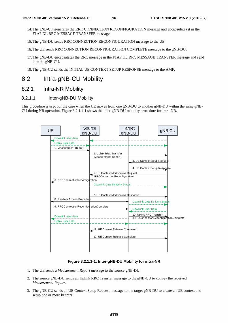
This procedure is used for the case when the UE moves from one gNB-DU to another gNB-DU within the same gNB-CU during NR operation. Figure 8.2.1.1-1 shows the inter-gNB-DU mobility procedure for intra-NR.
UESource
gNB-DUTarget
gNB-DUgNB-CU
1. Measurement Report
2. Uplink RRC Transfer(Measurement Report)
3. UE Context Setup Request
4. UE Context Setup Response
5. UE Context Modification Request(RRCConnectionReconfiguration)
9. RRCConnectionReconfigurationComplete
6. RRCConnectionReconfiguration
10. Uplink RRC Transfer(RRCConnectionReconfigurationComplete)
8. Random Access Procedure
11. UE Context Release Command
12. UE Context Release Complete
Downlink user data
Uplink user data
Downlink Data Delivery Status
Downlink User Data
Downlink user data
Uplink user data
7. UE Context Modification Response
Downlink Data Delivery Status
Figure 8.2.1.1-1: Inter-gNB-DU Mobility for intra-NR
1. The UE sends a Measurement Report message to the source gNB-DU.
2. The source gNB-DU sends an Uplink RRC Transfer message to the gNB-CU to convey the received Measurement Report.
3. The gNB-CU sends an UE Context Setup Request message to the target gNB-DU to create an UE context and setup one or more bearers.

ETSI
ETSI TS 138 401 V15.2.0 (2018-07)173GPP TS 38.401 version 15.2.0 Release 15
4. The target gNB-DU responds to the gNB-CU with an UE Context Setup Response message.
5. The gNB-CU sends a UE Context Modification Request message to the source gNB-DU, which includes a generated RRCConnectionReconfiguration message and indicates to stop the data transmission for the UE. The source gNB-DU also sends a Downlink Data Delivery Status frame to inform the gNB-CU about the unsuccessfully transmitted downlink data to the UE.
6. The source gNB-DU forwards the received RRCConnectionReconfiguration message to the UE.
7. The source gNB-DU responds to the gNB-CU with the UE Context Modification Response message.
8. A Random Access procedure is performed at the target The target gNB-DU sends a Downlink Data Delivery Status frame to inform the gNB-CU. Downlink packets, which may include PDCP PDUs not successfully transmitted in the source gNB-DU, are sent from the gNB-CU to the target gNB-DU.
NOTE: It is up to gNB-CU implementation whether to start sending DL User Data to gNB-DU before or after reception of the Downlink Data Delivery Status.
gNB-DU.
9. The UE responds to the target gNB-DU with an RRCConnectionReconfigurationComplete message.
10. The target gNB-DU sends an Uplink RRC Transfer message to the gNB-CU to convey the received RRCConnectionReconfigurationComplete message. Downlink packets are sent to the UE. Also, uplink packets are sent from the UE, which are forwarded to the gNB-CU through the target gNB-DU.
11. The gNB-CU sends an UE Context Release Command message to the source gNB-DU.
12. The source gNB-DU releases the UE context and responds the gNB-CU with an UE Context Release Complete message.
8.2.1.2 Intra-gNB-DU handover
This procedure is used for the case that UE moves from one cell to another cell within the same gNB-DU or for the case that intra-cell handover is performed during NR operation, and supported by UE Context Modification (gNB-CU initiated) procedure as specified in TS 38.473 [4]. When the intra-cell handover is performed, the gNB-CU provides new UL GTP TEID to the gNB-DU and gNB-DU provides new DL GTP TEID to the gNB-CU.The gNB-DU shall continue sending UL PDCP PDUs to the gNB-CU with the previous UL GTP TEID until it re-establishes the RLC, and use the new UL GTP TEID after RLC re-establishment. The gNB-CU shall continue sending DL PDCP PDUs to the gNB-DU with the previous DL GTP TEID until it performs PDCP re-establishment or PDCP data recovery, and use the new DL GTP TEID starting with the PDCP re-establishment or data recovery.
8.2.2 EN-DC Mobility
8.2.2.1 Inter-gNB-DU Mobility using MCG SRB
This procedure is used for the case the UE moves from one gNB-DU to another gNB-DU within the same gNB-CU when only MCG SRB is available during EN-DC operation. Figure 8.2.2.1-1 shows the inter-gNB-DU mobility procedure using MCG SRB in EN-DC.

ETSI
ETSI TS 138 401 V15.2.0 (2018-07)183GPP TS 38.401 version 15.2.0 Release 15
UESource
gNB-DUTarget
gNB-DUgNB-CU
1. Measurement Report
2. SgNB Modification Request
3. UE Context Setup Request
4. UE Context Setup Response
10. Random Access Procedure
12. UE Context Release Command
13. UE Context Release Complete
Downlink user data
Uplink user data
Downlink User Data
Downlink user data
Uplink user data
MeNB
5. SgNB Modification Request Acknowledge
8. RRC Reconfiguration procedure is performed between the MeNB and the UE.
9. SgNB Reconfiguration Complete
6. UE Context Modification Request
7. UE Context Modification Response
Downlink Data Delivery Status
Downlink Data Delivery Status
Figure 8.2.2.1-1: Inter-gNB-DU Mobility using MCG SRB in EN-DC
1. The UE sends a Measurement Report message to the MeNB.
2. The MeNB sends an SgNB Modification Request message.
3. The gNB-CU sends an UE Context Setup Request message to the target gNB-DU to create an UE context and setup one or more bearers.
4. The target gNB-DU responds the gNB-CU with an UE Context Setup Response message.
5. The gNB-CU responds the MeNB with an SgNB Modification Request Acknowledge message.
6. The gNB-CU sends a UE Context Modification Request message to the source gNB-DU indicating to stop the data transmission to the UE. The source gNB-DU also sends a Downlink Data Delivery Status frame to inform the gNB-CU about the unsuccessfully transmitted downlink data to the UE.
7. The source gNB-DU responds the gNB-CU with an UE Context Modification Response message.
8. The MeNB and the UE perform RRC Reconfiguration procedure.
9. The MeNB sends an SgNB Reconfiguration Complete message to the gNB-CU..
10. Random Access procedure is performed at the target gNB-DU. The target gNB-DU sends a Downlink Data Delivery Status frame to inform the gNB-CU. Downlink packets, which may include PDCP PDUs not successfully transmitted in the source gNB-DU, are sent from the gNB-CU to the target gNB-DU. Downlink packets are sent to the UE. Also, uplink packets are sent from the UE, which are forwarded to the gNB-CU through the target gNB-DU.
NOTE: It is up to gNB-CU implementation whether to start sending DL User Data to gNB-DU before or after reception of the Downlink Data Delivery Status.
11. The gNB-CU sends an UE Context Release Command message to the source gNB-DU.
ETSI
ETSI TS 138 401 V15.2.0 (2018-07)193GPP TS 38.401 version 15.2.0 Release 15
12. The source gNB-DU releases the UE context and responds the gNB-CU with an UE Context Release Complete message.
8.2.2.2 Inter-gNB-DU Mobility using SCG SRB
This procedure is used for the case the UE moves from one gNB-DU to another gNB-DU when SCG SRB is available during EN-DC operation. The procedure is the same as inter-gNB-DU Mobility for intra-NR as defined in clause 8.2.1.1.
8.3 Mechanism of centralized retransmission of lost PDUs
8.3.1 Centralized Retransmission in Intra gNB-CU Cases
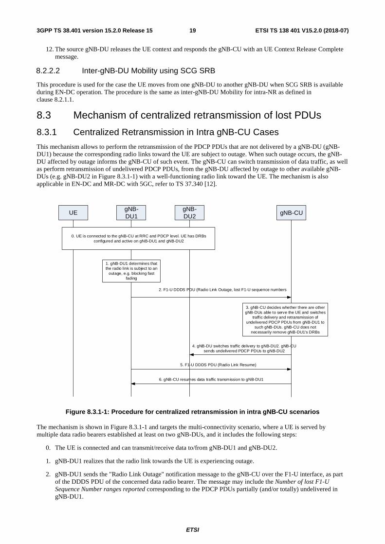
This mechanism allows to perform the retransmission of the PDCP PDUs that are not delivered by a gNB-DU (gNB-DU1) because the corresponding radio links toward the UE are subject to outage. When such outage occurs, the gNB-DU affected by outage informs the gNB-CU of such event. The gNB-CU can switch transmission of data traffic, as well as perform retransmission of undelivered PDCP PDUs, from the gNB-DU affected by outage to other available gNB-DUs (e.g. gNB-DU2 in Figure 8.3.1-1) with a well-functioning radio link toward the UE. The mechanism is also applicable in EN-DC and MR-DC with 5GC, refer to TS 37.340 [12].
UEgNB-DU1
gNB-DU2
6. gNB-CU resumes data traffic transmission to gNB-DU1
5. F1-U DDDS PDU (Radio Link Resume)
gNB-CU
0. UE is connected to the gNB-CU at RRC and PDCP level. UE has DRBs configured and active on gNB-DU1 and gNB-DU2
4. gNB-DU switches traffic delivery to gNB-DU2. gNB-CU sends undelivered PDCP PDUs to gNB-DU2
2. F1-U DDDS PDU (Radio Link Outage, lost F1-U sequence numbers
1. gNB-DU1 determines that the radio link is subject to an
outage, e.g. blocking fast fading
3. gNB-CU decides whether there are other gNB-DUs able to serve the UE and switches
traffic delivery and retransmission of undelivered PDCP PDUs from gNB-DU1 to
such gNB-DUs. gNB-CU does not necessarily remove gNB-DU1's DRBs
Figure 8.3.1-1: Procedure for centralized retransmission in intra gNB-CU scenarios
The mechanism is shown in Figure 8.3.1-1 and targets the multi-connectivity scenario, where a UE is served by multiple data radio bearers established at least on two gNB-DUs, and it includes the following steps:
0. The UE is connected and can transmit/receive data to/from gNB-DU1 and gNB-DU2.
1. gNB-DU1 realizes that the radio link towards the UE is experiencing outage.
2. gNB-DU1 sends the "Radio Link Outage" notification message to the gNB-CU over the F1-U interface, as part of the DDDS PDU of the concerned data radio bearer. The message may include the Number of lost F1-U Sequence Number ranges reported corresponding to the PDCP PDUs partially (and/or totally) undelivered in gNB-DU1.
ETSI
ETSI TS 138 401 V15.2.0 (2018-07)203GPP TS 38.401 version 15.2.0 Release 15
3. gNB-CU decides to switch data traffic transmission and retransmission of PDCP PDUs that were undelivered in gNB-DU1 via gNB-DU2. gNB-CU stops sending downlink traffic to gNB-DU1. The radio leg between gNB-DU1 and the UE is not necessarily removed.
4. gNB-CU starts sending traffic (namely new PDUs and potentially retransmitted PDUs) to gNB-DU2.
5. If gNB-DU1 realizes that the radio link of the concerned data radio bearer is back in normal operation, it may send a "Radio Link Resume" notification message as part of the DDDS PDU over the F1-U interface to inform the gNB-CU that the radio link can be used again for the concerned data radio bearer.
6. gNB-CU may start sending traffic (namely new PDUs and potentially retransmitted PDUs) of the concerned data radio bearer via gNB-DU1 again.
8.4 Multi-Connectivity operation
8.4.1 Secondary Node Addition
8.4.1.1 EN-DC
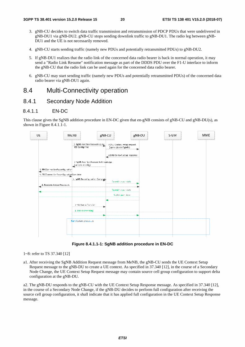
This clause gives the SgNB addition procedure in EN-DC given that en-gNB consists of gNB-CU and gNB-DU(s), as shown in Figure 8.4.1.1-1.
Figure 8.4.1.1-1: SgNB addition procedure in EN-DC
1~8: refer to TS 37.340 [12]
a1. After receiving the SgNB Addition Request message from MeNB, the gNB-CU sends the UE Context Setup Request message to the gNB-DU to create a UE context. As specified in 37.340 [12], in the course of a Secondary Node Change, the UE Context Setup Request message may contain source cell group configuration to support delta configuration at the gNB-DU.
a2. The gNB-DU responds to the gNB-CU with the UE Context Setup Response message. As specified in 37.340 [12], in the course of a Secondary Node Change, if the gNB-DU decides to perform full configuration after receiving the source cell group configuration, it shall indicate that it has applied full configuration in the UE Context Setup Response message.

ETSI
ETSI TS 138 401 V15.2.0 (2018-07)213GPP TS 38.401 version 15.2.0 Release 15
8.4.2 Secondary Node Release (MN/SN initiated)
8.4.2.1 EN-DC
This clause gives the SgNB release procedure in EN-DC given that the en-gNB consists of a gNB-CU and gNB-DU(s).
MN initiated SN Release
UE MeNB gNB-CU gNB-DU S-GW
3. RRCConnectionReconfiguration
4. RRCConnectionReconfigurationComplete
5. SN Status Transfer
6. Data Forwarding
7. Path Update procedure
1. SgNB Release Request
8. UE Context Release
MME
a3. UE Context Release Request
a4. UE Context Release Response
a1. UE Context Modification Request
a2. UE Context Modification Response
2. SgNB Release Request Acknowledge
Figure 8.4.2.1-1 SgNB release procedure in EN-DC (MN initiated)
1~8: refer to TS 37.340 [12]
NOTE: The timing of sending the Step 2 SgNB Release Request Acknowledge message is an example, it may be sent e.g. after step a1 or after a2 and it is up to implementation.
a1. After receiving SgNB Release Request message from MeNB, gNB-CU sends the UE Context Modification Request message to gNB-DU to stop the data transmission for the UE. It is up to gNB-DU implementation when to stop the UE scheduling.
a2. gNB-DU responds to gNB-CU with UE Context Modification Response message.
a3. After receiving the UE Context Release message from MeNB, the gNB-CU sends the UE Context Release Request message to the gNB-DU to release the UE context.
a4. The gNB-DU responds to the gNB-CU with the UE Context Release Response message.
SN initiated SN Release
UE MeNB gNB-CU gNB-DU S-GW
1. SgNB Release Required
3. RRCConnectionReconfiguration
4. RRCConnectionReconfigurationComplete
5. SNStatus Transfer
6. Data Forwarding
7. Path Update procedure
2. SgNB Release Confirm
8. UE Context Release
MME
a3. UE Context Release Request
a4. UE Context Release Response
a1. UE Context Modification Request
a2. UE Context Modification Response
Figure 8.4.2.1-2 SgNB release procedure in EN-DC (SN initiated)

ETSI
ETSI TS 138 401 V15.2.0 (2018-07)223GPP TS 38.401 version 15.2.0 Release 15
1~8: refer to TS 37.340 [12]
a1. gNB-CU sends the UE Context Modification Request message to gNB-DU to stop the data transmission for the UE. It is up to gNB-DU implementation when to stop the UE scheduling. This step may occur before step 1.
a2. gNB-DU responds to gNB-CU with UE Context Modification Response message.
a3. After receiving the UE Context Release message from MeNB, the gNB-CU sends the UE Context Release Request message to the gNB-DU to release the UE context.
a4. The gNB-DU responds to the gNB-CU with the UE Context Release Response message.
8.5 F1 Startup and cells activation This function allows to setup the F1 interface between a gNB-DU and a gNB-CU and it allows to activate the gNB-DU cells.
gNB-DU gNB-CU
3. F1 Setup Response
1. F1 Setup Request
0. Pre-operational state
gNB/eNB5GC
2. NG Setup/gNB Configuration Update
6. Xn/X2 Setup
4. gNB-CU Configuration Update
5. gNB-CU Configuration Update Ack
Figure 8.5-1: F1 startup and cell activation
0. The gNB-DU and its cells are configured by OAM in the F1 pre-operational state. The gNB-DU has TNL connectivity toward the gNB-CU.
1. The gNB-DU sends an F1 Setup Request message to the gNB-CU including a list of cells that are configured and ready to be activated.
2. In NG-RAN, the gNB-CU ensures the connectivity toward the core network. For this reason, the gNB-CU may initiate either the NG Setup or the gNB Configuration Update procedure towards 5GC.
3. The gNB-CU sends an F1 Setup Response message to the gNB-DU that optionally includes a list of cells to be activated. If the gNB-DU succeeds to activate the cell(s), then the cells become operational. If the gNB-DU fails to activate some cell(s), the gNB-DU may initiate the gNB-DU Configuration Update procedure towards the gNB-CU. The gNB-DU includes in the gNB-DU Configuration Update message the cell(s) that are active (i.e., the cell(s) for which the gNB-DU should be able to serve UEs). The gNB-DU may also indicate that the cell(s) that failed to activate should be deleted, in which case the gNB-CU removes the corresponding cell(s) information.
4. The gNB-CU may send a gNB-CU Configuration Update message to the gNB-DU that optionally includes a list of cells to activated, e.g., in case that these cells were not activated using the F1 Setup Response message.
5. The gNB-DU replies with a gNB-DU Configuration Update Acknowledge message that optionally includes a list of cells that failed to be activated.
ETSI
ETSI TS 138 401 V15.2.0 (2018-07)233GPP TS 38.401 version 15.2.0 Release 15
6. The gNB-CU may initiate either the Xn Setup towards a neighbour NG-RAN node or the EN-DC X2 Setup procedure towards a neighbour eNB.
NOTE: In case that the F1 Setup Response is not used to activate any cell, step 2 may be performed after step 3.
Over the F1 interface between a gNB-CU and a gNB-DU pair, the following two cell states are possible:
- Inactive: the cell is known by both the gNB-DU and the gNB-CU. The cell shall not serve UEs;
- Active: the cell is known by both the gNB-DU and the gNB-CU. The cell should be able to serve UEs.
The gNB-CU decides whether the cell state should be Inactive or Active. The gNB-CU can request the gNB-DU to change the cell state using the F1 Setup Response, the gNB-DU Configuration Update Acknowledge, or the gNB-CU Configuration Update messages. The gNB-DU can confirm (or reject) a request to change the cell state using the gNB-DU Configuration Update or the gNB-CU Configuration Update Acknowledge messages.
8.6 RRC state transition
8.6.1 RRC connected to RRC inactive
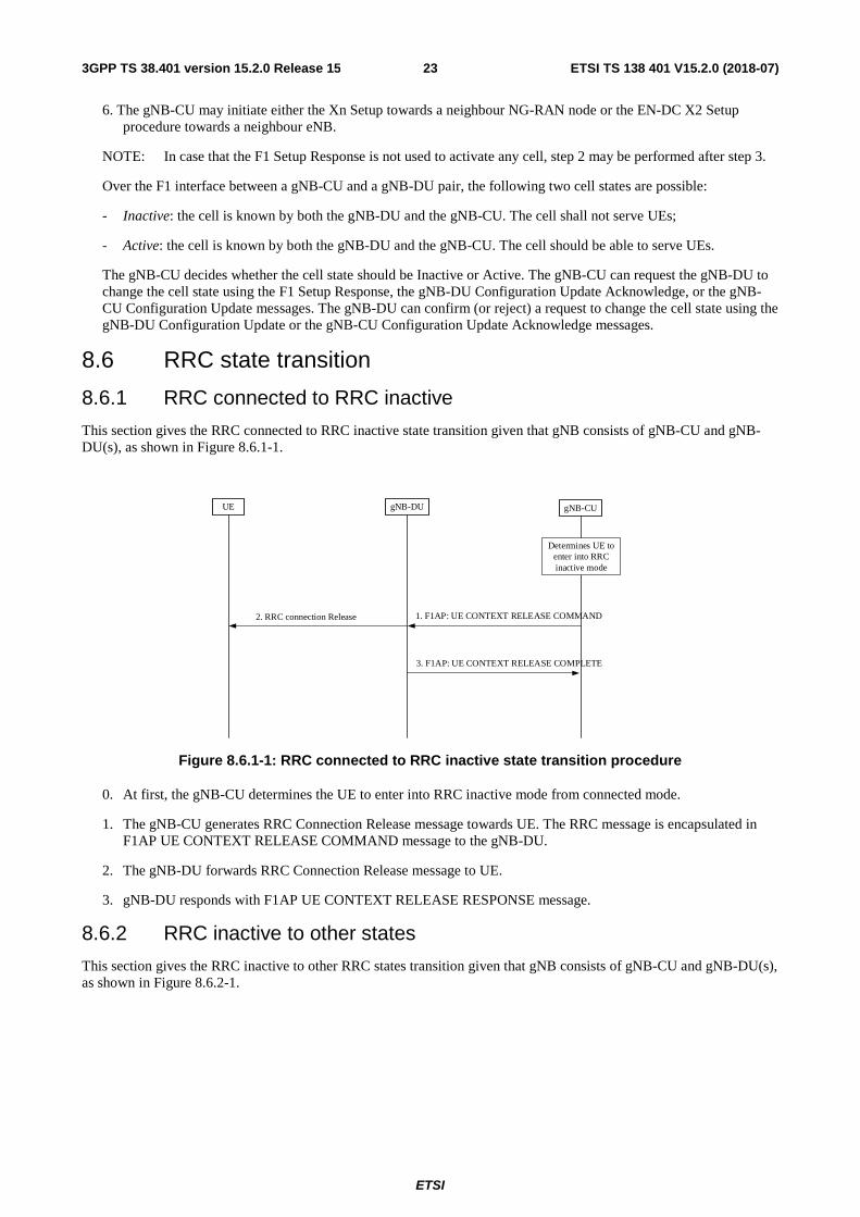
This section gives the RRC connected to RRC inactive state transition given that gNB consists of gNB-CU and gNB-DU(s), as shown in Figure 8.6.1-1.
gNB-CUgNB-DU
UE
3. F1AP: UE CONTEXT RELEASE COMPLETE
Determines UE to enter into RRC inactive mode
1. F1AP: UE CONTEXT RELEASE COMMAND2. RRC connection Release
Figure 8.6.1-1: RRC connected to RRC inactive state transition procedure
0. At first, the gNB-CU determines the UE to enter into RRC inactive mode from connected mode.
1. The gNB-CU generates RRC Connection Release message towards UE. The RRC message is encapsulated in F1AP UE CONTEXT RELEASE COMMAND message to the gNB-DU.
2. The gNB-DU forwards RRC Connection Release message to UE.
3. gNB-DU responds with F1AP UE CONTEXT RELEASE RESPONSE message.
8.6.2 RRC inactive to other states
This section gives the RRC inactive to other RRC states transition given that gNB consists of gNB-CU and gNB-DU(s), as shown in Figure 8.6.2-1.

ETSI
ETSI TS 138 401 V15.2.0 (2018-07)243GPP TS 38.401 version 15.2.0 Release 15
gNB-CUgNB-DU
6. F1AP: UE CONTEXT SETUP RESPONSE
UE
5. F1AP: UE CONTEXT SETUP REQUEST
3. RRC Resume Request 4. F1AP: INITIAL UL RRC MESSAGE TRANSFER
7. F1AP: DL RRC MESSAGE TRANSFER8. RRC Resume/Reject/Setup/Release
9. RRC Resume/Setup Complete 10. F1AP: UL RRC MESSAGE TRANSFER
1. F1AP: Paging2. Paging
Figure 8.6.2-1: RRC inactive to other RRC states transition procedure
1. If data is received from 5GC, the gNB-CU sends F1AP Paging message to gNB-DU.
2. The gNB-DU sends RAN Paging message to UE.
NOTE: step 1 and 2 only exist in case of DL data arrival.
3. UE sends RRC resume request either upon RAN-based paging, UL data arrival or RNA update.
4. The gNB-DU includes RRC resume request in a non-UE associated F1AP INITIAL UL RRC MESSAGE TRANSFER message and transfer to the gNB-CU.
5. For UE Inactive to UE Active transitions, excluding transitions due to signalling exchange only, the gNB-CU allocates gNB-CU UE F1AP ID and sends F1AP UE CONTEXT SETUP REQUEST message to gNB-DU, which may include SRB ID(s) and DRB ID(s) to be setup.
6. The gNB-DU responds with F1AP UE CONTEXT SETUP RESPONSE message, which contains RLC/MAC/PHY configuration of SRB and DRBs provided by the gNB-DU.
NOTE: step 5 and 6 exist for inactive to active transitions, excluding transitions due to signalling exchange only. When gNB-CU successfully retrieves and verifies the UE context, it may decide to let the UE enter into RRC active mode. gNB-CU shall trigger UE context setup procedure between gNB-CU and gNB-DU, during which both SRB1, SRB2 and DRB(s) can be setup. For signalling exchange only transitions, gNB-CU does not trigger UE Context Setup procedure. For inactive to Idle transitions the gNB-CU does not trigger the UE Context Setup procedure.
7. The gNB-CU generates RRC resume/setup/reject/release message towards UE. The RRC message is encapsulated in F1AP DL RRC MESSAGE TRANSFER message together with SRB ID.
8. The gNB-DU forwards RRC message to UE either over SRB0 or SRB1 as indicated by the SRB ID.
NOTE: in step 7, it is expected that gNB-CU generates RRC resume message for inactive to active state transition(for both cases of signaling exchange only, and UP data exchange), generates RRC setup message for fallback to establish a new RRC connection, and generates either RRC release message without suspend configuration for inactive to idle state transition, or RRC release message with suspend configuration to remain in inactive state. If step 5 and 6 are not performed, the gNB-DU deduces the SRB on which to deliver the RRC message in step 7 from the SRB ID, i.e. SRB ID “0” corresponds to SRB0, SRB ID “1” corresponds to SRB1.

ETSI
ETSI TS 138 401 V15.2.0 (2018-07)253GPP TS 38.401 version 15.2.0 Release 15
9. UE sends RRC resume/setup complete message to the gNB-DU.
10. The gNB-DU encapsulates RRC in F1AP UL RRC MESSAGE TRANSFER message and send to the gNB-CU.
NOTE: step 9 and step 10 exist for inactive to active state transition (for both cases of signaling exchange only, and UP data exchange). UE generates RRC resume/setup complete message for resume the existing RRC connection or fallback to a new RRC connection respectively.
8.7 RRC connection reestablishment This procedure is used for the case that UE tries to reestablish the RRC connection, as shown in Figure 8.7-1.
UE gNB-DU gNB-CU
3.RRC Connection ReestablishmentRequest(old C-RNTI, old PCI) 4.Initial UL RRC message (new C-RNTI, RRC message)
9.UE Context Modification Request
gNB
1. Preamble
2. RAR
Allocate new C-RNTI and SRB1 configuration
10.UE Context Modification Response
7.RRC Connection Reestablishment Complete 8.UL RRC Message Transfer
11.DL RRC Message Transfer12.RRC Connection Reconfiguration
13.RRC Connection Reconfiguration Complete
14.UL RRC Message Transfer
Find UE context based on old gNB-DU UE F1AP ID, replace old C-RNTI/PCI with new C-RNTI/PCI
9'.UE Context Modification Required
10'.UE Context Modification Confirm
5.DL RRC Message Transfer (old gNB-DU F1AP UE ID)6. RRC Connection Reestablishment
Figure 8.7-1: RRC connection reestablishment procedure
1. UE sends preamble to the gNB-DU.
2. The gNB-DU allocates new C-RNTI and responds UE with RAR.

ETSI
ETSI TS 138 401 V15.2.0 (2018-07)263GPP TS 38.401 version 15.2.0 Release 15
3. The UE sends RRC CONNECTION REESTABLISHMENT REQUEST message to the gNB-DU, which contains old C-RNTI and old PCI.
4. The gNB-DU includes the RRC message and, if the UE is admitted, the corresponding low layer configuration for the UE in the F1-AP INITIAL UL RRC MESSAGE TRANSFER message and transfers to the gNB-CU. The INITAIL UL RRC MESSAGE TRANSFER message should include C-RNTI.
5. The gNB-CU includes RRC CONNECTION REESTABLISHMENT message and old gNB-DU F1AP UE ID into F1AP DL RRC MESSAGE TRANSFER message and transfers to the gNB-DU.
6. The gNB-DU retrieves UE context based on old gNB-DU F1AP UE ID, replaces old C-RNTI/PCI with new C-RNTI/PCI. It sends RRC CONNECTION REESTABLISHMENT message to UE.
7-8. The UE sends RRC CONNECTION REESTABLISHMENT COMPLETE message to the gNB-DU. The gNB-DU encapsulates the RRC message in F1AP UL RRC MESSAGE TRANSFER message and sends to gNB-CU.
9-10. The gNB-CU triggers UE context modification procedure by sending UE CONTEXT MODIFICIATION REQUEST, which may include DRBs to be modified and released list. The gNB-DU responses with UE CONTEXT MODIFICATION RESPONSE message.
9'-10'. The gNB-DU triggers UE context modification procedure by sending UE CONTEXT MODIFICIATION REQUIRED, which may include DRBs to be modified and released list. The gNB-CU responses with UE CONTEXT MODIFICATION CONFIRM message.
NOTE: Here it is assumed that UE accesses from the original gNB-DU where the UE contexts are available for that UE, and either step 9-10 or step 9’ and 10’ may exist or both could be skipped.
NOTE: If UE accesses from a gNB-DU other than the original one, gNB-CU should trigger UE CONTEXT SETUP procedure towards this new gNB-DU.
11-12. The gNB-CU includes RRC CONNECTION RECONFIGURATION message into F1AP DL RRC MESSAGE TRANSFER message and transfers to the gNB-DU. The gNB-DU forwards it to the UE.
13-14. The UE sends RRC CONNECTION RECONFIGURATION COMPLETE message to the gNB-DU, and gNB-DU forwards it to the gNB-CU.
8.8 Multiple TNLAs for F1-C In the following, the procedure for managing multiple TNLAs for F1-C is described.
gNB-DU gNB-CU
3. F1 SETUP RESPONSE
2. F1 SETUP REQUEST
4. GNB-CU CONFIGURATION UPDATE
5. GNB-CU CONFIGURATION UPATE ACK
1. TNLA establishment (TNLA1)
Figure 8.8-1: Managing multiple TNLAs for F1-C.
1. The gNB-DU establishes the first TNLA with the gNB-CU using a configured TNL address.
ETSI
ETSI TS 138 401 V15.2.0 (2018-07)273GPP TS 38.401 version 15.2.0 Release 15
2-3. Once the TNLA has been established, the gNB-DU initiates the F1 Setup procedure to exchange application level configuration data
4-5. When needed, the gNB-CU may add additional TNL Endpoint(s) to be used for F1-C signalling between the gNB-CU and the gNB-DU pair using the gNB-CU Configuration Update procedure. The gNB-CU Configuration Update procedure also allows the gNB-CU to request the gNB-DU to modify or release TNLA(s).
Note: Further clarification regarding the establishment of the TNLA are needed.
The F1AP UE TNLA binding is a binding between a F1AP UE association and a specific TNL association for a given UE. After the F1AP UE TNLA binding is created, the gNB-CU can update the UE TNLA binding by sending the F1AP message for the UE to the gNB-DU via a different TNLA. The gNB-DU shall update the F1AP UE TNLA binding with the new TNLA.
8.9 Overall procedures involving E1 and F1 The following clauses describe the overall procedures involving E1 and F1.
8.9.1 UE Initial Access
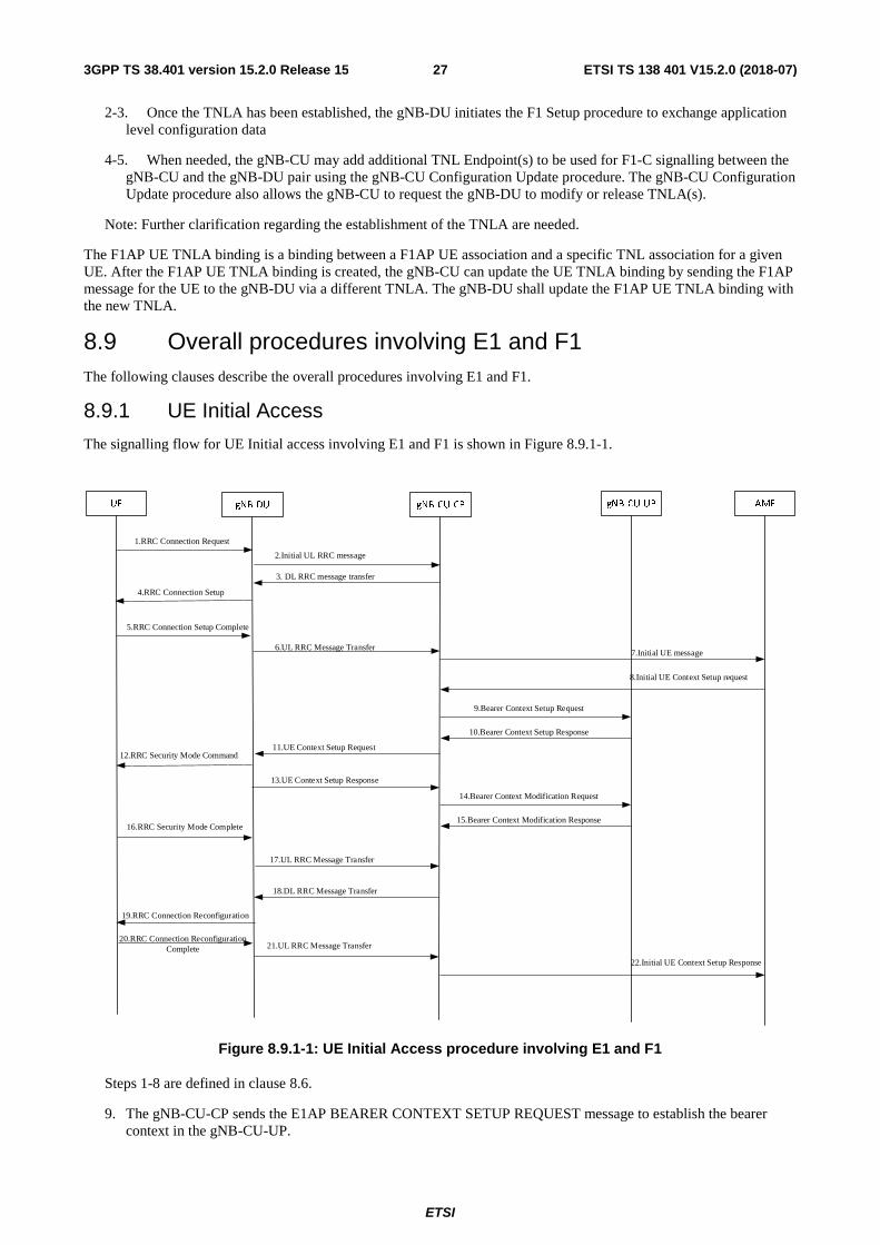
The signalling flow for UE Initial access involving E1 and F1 is shown in Figure 8.9.1-1.
1.RRC Connection Request
3. DL RRC message transfer
2.Initial UL RRC message
4.RRC Connection Setup
5.RRC Connection Setup Complete
6.UL RRC Message Transfer
11.UE Context Setup Request
7.Initial UE message
8.Initial UE Context Setup request
13.UE Context Setup Response
12.RRC Security Mode Command
16.RRC Security Mode Complete
18.DL RRC Message Transfer
17.UL RRC Message Transfer
19.RRC Connection Reconfiguration
20.RRC Connection Reconfiguration Complete 21.UL RRC Message Transfer
22.Initial UE Context Setup Response
9.Bearer Context Setup Request
10.Bearer Context Setup Response
14.Bearer Context Modification Request
15.Bearer Context Modification Response
AMFUE gNB-DU gNB-CU-CP gNB-CU-UP
Figure 8.9.1-1: UE Initial Access procedure involving E1 and F1
Steps 1-8 are defined in clause 8.6.
9. The gNB-CU-CP sends the E1AP BEARER CONTEXT SETUP REQUEST message to establish the bearer context in the gNB-CU-UP.

ETSI
ETSI TS 138 401 V15.2.0 (2018-07)283GPP TS 38.401 version 15.2.0 Release 15
10 The gNB-CU-UP sends the E1AP BEARER CONTEXT SETUP RESPONSE message to gNB-CU-CP, including F1-U UL TEID and transport layer address allocated by gNB-CU-UP.
Steps 11-13 are defined in clause 8.6.
14. The gNB-CU-CP sends the E1AP BEARER CONTEXT MODIFICATION REQUEST message to the gNB-CU-UP, including F1-U DL TEID and transport layer address allocated by gNB-DU.
15. The gNB-CU-UP sends the E1AP BEARER CONTEXT MODIFICATION RESPONSE message to the gNB-CU-CP.
Steps 16-22 are defined in clause 8.6.
NOTE: 14-15 and 16-17 can happen in parallel, but both are before 18.
8.9.2 Bearer context setup over F1-U
Figure 8.9.2-1 shows the procedure used to setup the bearer context in the gNB-CU-UP.
gNB-DU gNB-CU-UP gNB-CU-CP
3. F1 UE context setup procedure
Downlink user data
Uplink user data
4. Bearer Context Modification Request
gNB
0. Bearer context setup is triggered
5. Bearer Context Modification Response
1. Bearer Context Setup Request
2. Bearer Context Setup Response
Figure 8.9.2-1: Bearer context setup over F1-U
0. Bearer context setup (e.g., following an SgNB Addition Request from the MeNB) is triggered in gNB-CU-CP.
1. The gNB-CU-CP sends a BEARER CONTEXT SETUP REQUEST message containing UL TNL address information for S1-U or NG-U, and if required, DL or UL TNL address information for X2-U or Xn-U to setup the bearer context in the gNB-CU-UP. For NG-RAN, the gNB-CU-CP decides flow-to-DRB mapping and sends the generated SDAP and PDCP configuration to the gNB-CU-UP.
2. The gNB-CU-UP responds with a BEARER CONTEXT SETUP RESPONSE message containing the UL TNL address information for F1-U, and DL TNL address information for S1-U or NG-U, and if required, DL or UL TNL address information for X2-U or Xn-U.
3. F1 UE context setup procedure is performed to setup one or more bearers in the gNB-DU.
4. The gNB-CU-CP sends a BEARER CONTEXT MODIFICATION REQUEST message containing the DL TNL address information for F1-U and PDCP status.
5. The gNB-CU-UP responds with a BEARER CONTEXT MODIFICATION RESPONSE message.

ETSI
ETSI TS 138 401 V15.2.0 (2018-07)293GPP TS 38.401 version 15.2.0 Release 15
8.9.3 Bearer context release over F1-U
8.9.3.1 gNB-CU-CP initiated bearer context release
Figure 8.9.3.1-1 shows the procedure used to release the bearer context in the gNB-CU-UP initiated by the gNB-CU-CP.
gNB-DU gNB-CU-UP gNB-CU-CP
3. F1 UE context modification procedure
1. Bearer Context Modification Request
gNB
0. Bearer context release is triggered
2. Bearer Context Modification Response
4. UE Context Release from MeNB
6. F1 UE context release procedure
5. Bearer Context Release Command
7. Bearer Context Release Complete
Figure 8.9.3.1-1: Bearer context release over F1-U – gNB-CU-CP initiated
0. Bearer context release (e.g., following an SgNB Release Request from the MeNB) is triggered in gNB-CU-CP.
1. The gNB-CU-CP sends a BEARER CONTEXT MODIFICATION REQUEST message to the gNB-CU-UP.
2. The gNB-CU-UP responds with a BEARER CONTEXT MODIFICATION RESPONSE carrying the PDCP UL/DL status.
3. F1 UE context modification procedure is performed to stop the data transmission for the UE. It is up to gNB-DU implementation when to stop the UE scheduling.
NOTE: step 1-3 are performed only if the PDCP status of the bearer(s) needs to be preserved e.g., for bearer type change.
4. The gNB-CU-CP may receive the UE CONTEXT RELEASE message from the MeNB in EN-DC operation as described in Section 8.4.2.1.
5. and 7. Bearer context release procedure is performed.
6. F1 UE context release procedure is performed to release the UE context in the gNB-DU.
8.9.3.2 gNB-CU-UP initiated bearer context release
Figure 8.9.3.2-1 shows the procedure used to release the bearer context in the gNB-CU-UP initiated by the gNB-CU-UP.

ETSI
ETSI TS 138 401 V15.2.0 (2018-07)303GPP TS 38.401 version 15.2.0 Release 15
gNB-DU gNB-CU-UP gNB-CU-CP
4. F1 UE context modification procedure
6. Bearer Context Release Command
gNB
0. Bearer context release is triggered
7. Bearer Context Release Complete
5. UE Context Release from MeNB
8. F1 UE context release procedure
1. Bearer Context Release Request
2. Bearer Context Modification Request
3. Bearer Context Modification Response
Figure 8.9.3.2-1: Bearer context release over F1-U – gNB-CU-UP initiated
0. Bearer context release is triggered in gNB-CU-UP e.g., due to local failure..
1. The gNB-CU-UP sends a BEARER CONTEXT RELEASE REQUEST message to request the release of the bearer context in the gNB-CU-UP. This message may contain the PDCP status.
2.- 5. If the PDCP status needs to be preserved, the E1 Bearer Context Modification and the F1 UE Context Modification procedures are performed. The E1 Bearer Context Modification procedure is used to convey data forwarding information to the gNB-CU-UP. The gNB-CU-CP may receive the UE Context Release from the MeNB.
6. The gNB-CU-CP sends a BEARER CONTEXT RELEASE COMMAND message to release the bearer context in the gNB-CU-UP.
7. The gNB-CU-UP responds with a BEARER CONTEXT RELEASE COMPLETE to confirm the release of the bearer context including also data forwarding information.
8. F1 UE context release procedure may be performed to release the UE context in the gNB-DU.
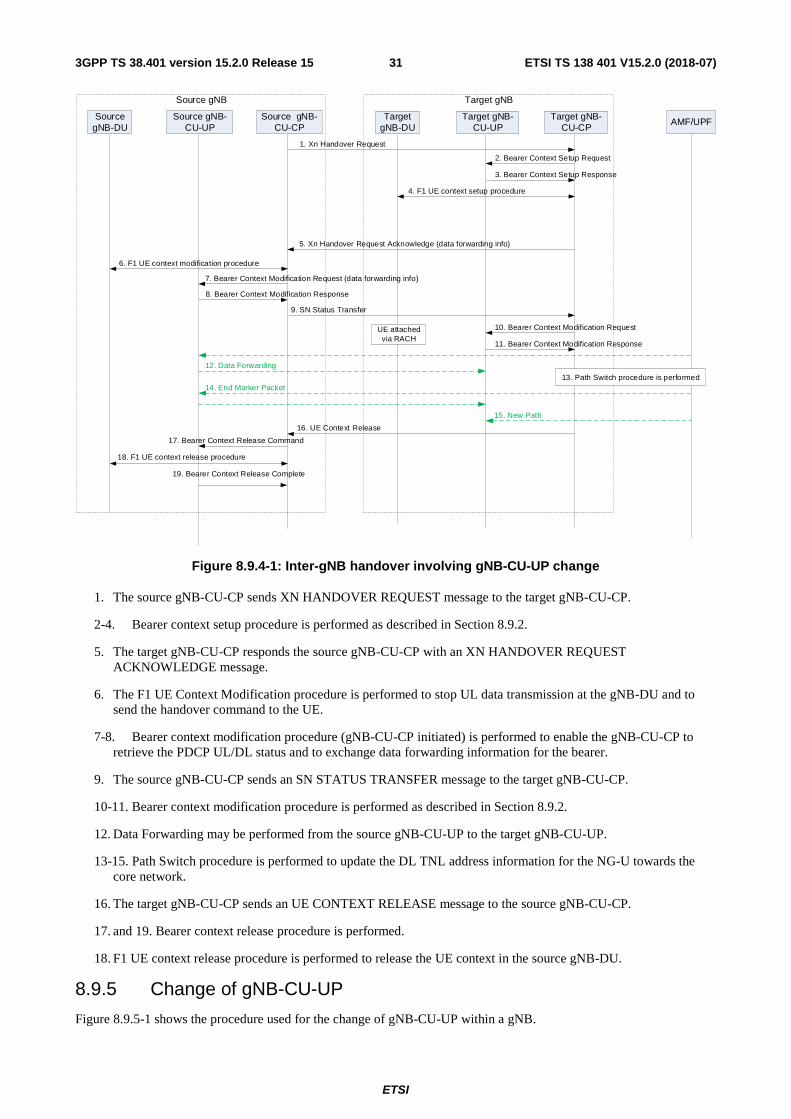
8.9.4 Inter-gNB handover involving gNB-CU-UP change
Figure 8.9.4-1 shows the procedure used for inter-gNB handover involving gNB-CU-UP change. Overall inter-gNB handover procedure is specified in TS 37.340 [12].
ETSI
ETSI TS 138 401 V15.2.0 (2018-07)313GPP TS 38.401 version 15.2.0 Release 15
Source gNB-CU-UP
Source gNB-CU-CP
6. F1 UE context modification procedure
10. Bearer Context Modification Request
Source gNB
11. Bearer Context Modification Response
Source gNB-DU
7. Bearer Context Modification Request (data forwarding info)
9. SN Status Transfer
12. Data Forwarding
AMF/UPF
14. End Marker Packet
15. New Path
Target gNB-CU-UP
Target gNB-CU-CP
Target gNB
TargetgNB-DU
4. F1 UE context setup procedure
1. Xn Handover Request
5. Xn Handover Request Acknowledge (data forwarding info)
13. Path Switch procedure is performed
16. UE Context Release
18. F1 UE context release procedure
8. Bearer Context Modification Response
2. Bearer Context Setup Request
3. Bearer Context Setup Response
UE attached via RACH
17. Bearer Context Release Command
19. Bearer Context Release Complete
Figure 8.9.4-1: Inter-gNB handover involving gNB-CU-UP change
1. The source gNB-CU-CP sends XN HANDOVER REQUEST message to the target gNB-CU-CP.
2-4. Bearer context setup procedure is performed as described in Section 8.9.2.
5. The target gNB-CU-CP responds the source gNB-CU-CP with an XN HANDOVER REQUEST ACKNOWLEDGE message.
6. The F1 UE Context Modification procedure is performed to stop UL data transmission at the gNB-DU and to send the handover command to the UE.
7-8. Bearer context modification procedure (gNB-CU-CP initiated) is performed to enable the gNB-CU-CP to retrieve the PDCP UL/DL status and to exchange data forwarding information for the bearer.
9. The source gNB-CU-CP sends an SN STATUS TRANSFER message to the target gNB-CU-CP.
10-11. Bearer context modification procedure is performed as described in Section 8.9.2.
12. Data Forwarding may be performed from the source gNB-CU-UP to the target gNB-CU-UP.
13-15. Path Switch procedure is performed to update the DL TNL address information for the NG-U towards the core network.
16. The target gNB-CU-CP sends an UE CONTEXT RELEASE message to the source gNB-CU-CP.
17. and 19. Bearer context release procedure is performed.
18. F1 UE context release procedure is performed to release the UE context in the source gNB-DU.
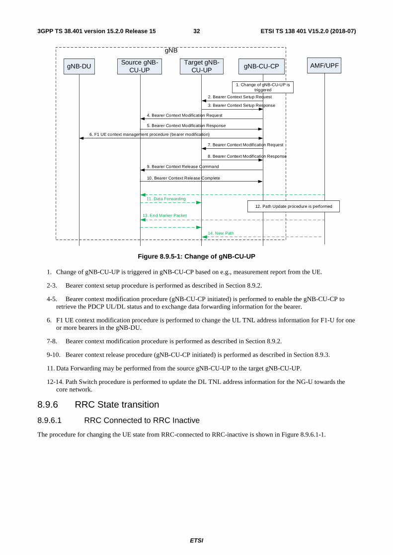
8.9.5 Change of gNB-CU-UP
Figure 8.9.5-1 shows the procedure used for the change of gNB-CU-UP within a gNB.
ETSI
ETSI TS 138 401 V15.2.0 (2018-07)323GPP TS 38.401 version 15.2.0 Release 15
Source gNB-CU-UP
Target gNB-CU-UP
gNB-CU-CP
6. F1 UE context management procedure (bearer modification)
2. Bearer Context Setup Request
gNB
1. Change of gNB-CU-UP is triggered
3. Bearer Context Setup Response
gNB-DU
9. Bearer Context Release Command
11. Data Forwarding
AMF/UPF
12. Path Update procedure is performed
13. End Marker Packet
14. New Path
10. Bearer Context Release Complete
7. Bearer Context Modification Request
8. Bearer Context Modification Response
4. Bearer Context Modification Request
5. Bearer Context Modification Response
Figure 8.9.5-1: Change of gNB-CU-UP
1. Change of gNB-CU-UP is triggered in gNB-CU-CP based on e.g., measurement report from the UE.
2-3. Bearer context setup procedure is performed as described in Section 8.9.2.
4-5. Bearer context modification procedure (gNB-CU-CP initiated) is performed to enable the gNB-CU-CP to retrieve the PDCP UL/DL status and to exchange data forwarding information for the bearer.
6. F1 UE context modification procedure is performed to change the UL TNL address information for F1-U for one or more bearers in the gNB-DU.
7-8. Bearer context modification procedure is performed as described in Section 8.9.2.
9-10. Bearer context release procedure (gNB-CU-CP initiated) is performed as described in Section 8.9.3.
11. Data Forwarding may be performed from the source gNB-CU-UP to the target gNB-CU-UP.
12-14. Path Switch procedure is performed to update the DL TNL address information for the NG-U towards the core network.
8.9.6 RRC State transition
8.9.6.1 RRC Connected to RRC Inactive
The procedure for changing the UE state from RRC-connected to RRC-inactive is shown in Figure 8.9.6.1-1.

ETSI
ETSI TS 138 401 V15.2.0 (2018-07)333GPP TS 38.401 version 15.2.0 Release 15
gNB-DU gNB-CU-UP gNB-CU-CP
3. F1 UE Context Release Command (w/ RRC-Release)
0. Decision of changing the UE state to RRC-inactive
1. Bearer Context Modifcation Request (w/ suspend indication)
2. Bearer Context Modifcation Response (report PDCP status for e.g., data reporting)
UE
4. RRC-Release
5. F1 UE Context Release Complete
Figure 8.9.6.1-1: RRC Connected to RRC Inactive state transition.
0. The gNB-CU-CP determines that the UE should enter RRC-inactive.
1. The gNB-CU-CP sends E1 Bearer Context Modification Request with a RRC Suspend indication to the gNB-CU-UP, which indicates that the UE is entering RCC-inactive state. The gNB-CU-CP keeps the F1 UL TEIDs.
2. The gNB-CU-UP sends the E1 Bearer Context Modification Response including the PDCP UL and DL status that may be needed for e.g., data volume reporting. The gNB-CU-UP keeps the Bearer Context, the UE-associated logical E1-connection, the NG-U related resource (e.g., NG-U DL TEIDs) and the F1 UL TEIDs.
3. The gNB-CU-CP sends the F1 UE Context Release Command to the gNB-DU serving the UE, together with the RRC-Release message to be sent to the UE.
NOTE: step 1 and 3 can be performed at the same time.
4. The gNB-DU sends the RRC-Release message to the UE.
5. The gNB-DU sends the F1 UE Context Release Complete to the gNB-CU-CP.
8.9.6.2 RRC Inactive to other states
The procedure for changing the UE state from RRC-inactive to RRC-connected is shown in Figure 8.9.6.2-1.

ETSI
ETSI TS 138 401 V15.2.0 (2018-07)343GPP TS 38.401 version 15.2.0 Release 15
gNB-DU gNB-CU-UP gNB-CU-CP
0. DL traffic detected on the NG-U tunnel(s)
2. Paging
UE
3. Paging
1. DL Data Notification
4. RRC-Resume-Reuqest
5. Inital UL RRC Message Transfer
8. Bearer Context Modification Request (w/ resume indication and DL TEIDs)
6. F1 UE Context Setup Request (UL TEIDs)
9. Bearer Context Modification Response
10. RRC-Resume
7. F1 UE Context Setup Request (DL TEIDs)
Figure 8.9.6.2-1: RRC Inactive to RRC Connected state transition.
0. The gNB-CU-UP receives DL data on NG-U interface.
1. The gNB-CU-UP sends E1 DL Data Notification message to the gNB-CU-CP.
2. The gNB-CU-CP initiates F1 Paging procedure.
3. The gNB-DU sends the RAN Paging message to the UE.
NOTE: step 0-3 are needed only in case of DL data.
4. The UE sends RRC-Resume-Request either upon RAN paging or UL data arrival.
5. The gNB-DU sends the F1 Initial UL RRC Message Transfer message to the gNB-CU-CP.
6. The gNB-CU-CP sends F1 UE Context Setup Request message including the stored F1 UL TEIDs to create the UE context in the gNB-DU.
7. The gNB-DU responds with the UE Context Setup Response message including the F1 DL TEIDs allocated for the DRBs.
8. The gNB-CU-CP sends E1 Bearer Context Modification Request with a RRC Resume indication, which indicates that the UE is resuming from RRC-inactive state. The gNB-CU-CP also includes the F1 DL TEIDs received from the gNB-DU in step 7.
9. The gNB-CU-UP responds with the E1 Bearer Context Modification Response.
10. The gNB-CU-CP and the UE preform the RRC-Resume procedure via the gNB-DU.
NOTE steps 8/9 and 10 can be performed in parallel.
ETSI
ETSI TS 138 401 V15.2.0 (2018-07)353GPP TS 38.401 version 15.2.0 Release 15
9 Synchronization
9.1 gNB Synchronization The gNB shall support a logical synchronization port for phase-, time- and/or frequency synchronization.
Logical synchronization port for phase- and time-synchronization shall provide:
1) accuracy that allows to meet the gNB requirements on maximum relative phase difference for all gNBs in synchronized TDD-unicast area;
2) continuous time without leap seconds traceable to common time reference for all gNBs in synchronized TDD-unicast area.
A logical synchronization port for phase- and time-synchronization may also be provided for e.g., all gNBs in FDD time domain inter-cell interference coordination synchronization area.
Furthermore common SFN initialization time shall be provided for all gNBs in synchronized TDD-unicast area.
Based on this information, the gNB may derive the SFN according to the following formula:
{ } ( ){ }SFNperiodtimeSFN mod= ,
where:
time time adjusted by the common SFN initialization time, in units of 10 ms to match the length of radio frame and accuracy accordingly;
period(SFN) SFN period.
In case gNB is connected via TDM interface, it may be used to frequency synchronize the gNB. The characteristics of the clock in the gNB shall be designed taking into account that the jitter and wander performance requirements on the interface are in accordance with network limits for output wander at traffic interfaces of either ITU-T Recommendation G.823 [8], ITU-T Recommendation G.824 [9] or network limits for the maximum output jitter and wander at any hierarchical interface of ITU-T Recommendation G.825 [10], whichever is applicable.
In case gNB is connected via Ethernet interface and the network supports Synchronous Ethernet, the gNB may use this interface to get frequency synchronization. In this case the design of the gNB clock should be done considering the jitter and wander performance requirements on the interface are as specified for output jitter and wander at EEC interfaces of ITU-T Recommendation G.8261/Y.1361 [11], defined in clause 9.2.1. Further considerations on Synchronous Ethernet recommendations and architectural aspects are defined in clause 12.2.1 and Annex A of ITU-T Recommendation G.8261/Y.1361 [11].
A configurable LTE TDD-offset of start frame shall be supported by all gNBs in synchronized TDD-unicast areas in order to achieve interoperability in coexistence scenarios.
10 NG-RAN interfaces
10.1 NG interface 3GPP TS 38.410 [14] specifies NG interface general aspects and principles.
10.2 Xn interface 3GPP TS 38.420 [15] specifies Xn interface general aspects and principles.
10.3 F1 interface 3GPP TS 38.470 [16] specifies F1 interface general aspects and principles.

ETSI
ETSI TS 138 401 V15.2.0 (2018-07)363GPP TS 38.401 version 15.2.0 Release 15
10.4 E1 interface 3GPP TS 38.460 [17] specifies E1 interface general aspects and principles.
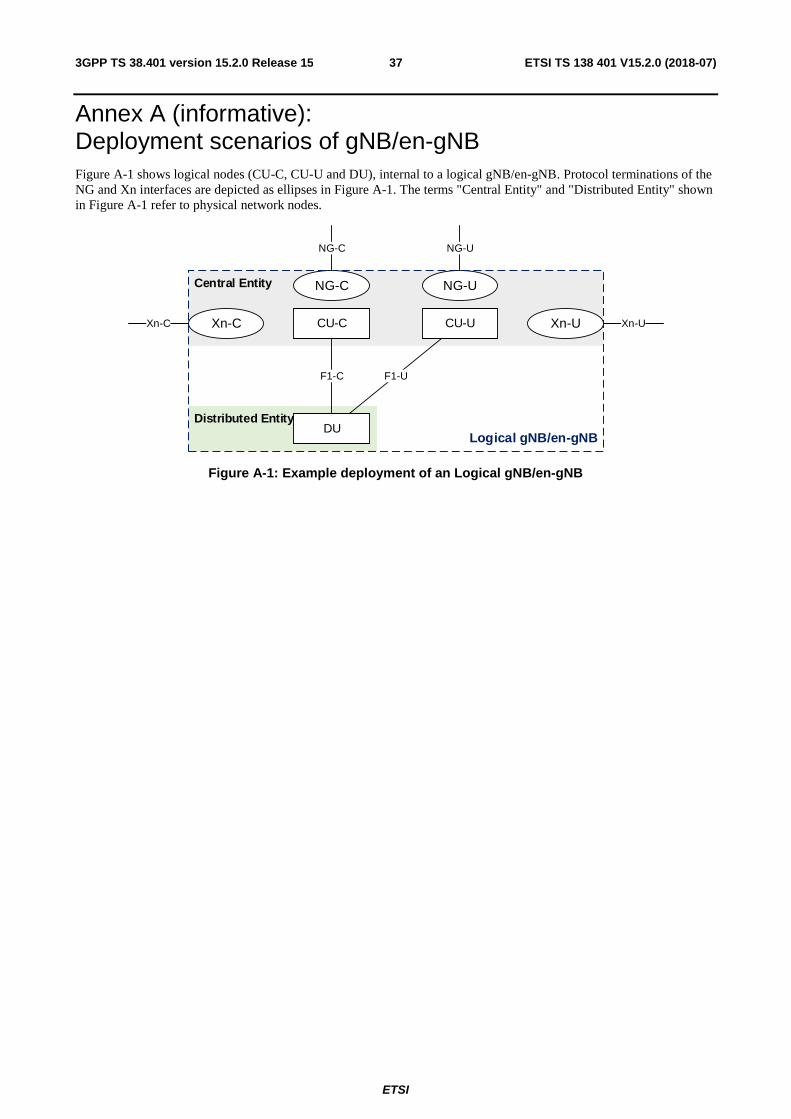
ETSI
ETSI TS 138 401 V15.2.0 (2018-07)373GPP TS 38.401 version 15.2.0 Release 15
Annex A (informative): Deployment scenarios of gNB/en-gNB Figure A-1 shows logical nodes (CU-C, CU-U and DU), internal to a logical gNB/en-gNB. Protocol terminations of the NG and Xn interfaces are depicted as ellipses in Figure A-1. The terms "Central Entity" and "Distributed Entity" shown in Figure A-1 refer to physical network nodes.
Distributed Entity
Central Entity NG-C
Xn-C
NG-U
Xn-U
F1-C F1-U
Logical gNB/en-gNB
NG-C NG-U
Xn-UXn-C CU-C CU-U
DU
Figure A-1: Example deployment of an Logical gNB/en-gNB

ETSI
ETSI TS 138 401 V15.2.0 (2018-07)383GPP TS 38.401 version 15.2.0 Release 15
Annex B (informative): Change History
Change history Date Meeting TDoc CR Rev Cat Subject/Comment New
version 2017-04 RAN3#95bis R3-171307 First Draft 0.0.1 2017-05 RAN3#96 R3-171962 Reflected agreed TP in RAN3#96.
Added new Clause 8 for overall procedure for gNB-CU/DU architecture
0.1.0
2017-06 RAN3#NR Ad Hoc
R3-172634 Reflected agreed TP in RAN3#NR Ad Hoc in 2017-06 (Qingdao) 0.2.0
2017-08 RAN3#97 R3-173449 Reflected agreed TP in RAN3#97 0.3.0 2017-10 RAN3#97bis R3-174237 Reflected agreed TP in RAN3#97bis 0.4.0 2017-10 RAN3#97bis R3-174258 Removed subclauses under 10.3 (moved to 38.470) 0.4.1 2017-11 RAN3#98 R3-175054 Reflected agreed TP in RAN3#98 0.5.0 2017-12 RP-78 RP-172545 Submit to RAN Plenary#78 for approval 1.0.0 2017-12 RP-78 TR Approved by RAN plenary 15.0.0 2018-03 RP-79 RP-180468 0007 1 - Correction on intra-gNB-DU handover 15.1.0 2018-06 RP-80 RP-181237 0001 5 B Introduction of SA NR (38.401 Baseline CR covering RAN3
agreements) 15.2.0
2018-06 RP-80 RP-181240 0008 4 B Introduction of Separation of CP and UP for Split Option 2 (38.401 Baseline CR covering RAN3 agreements)
15.2.0
2018-06 RP-80 RP-181238 0012 1 F CR to TS38.401 on UL blockage 15.2.0 2018-06 RP-80 RP-181238 0014 1 F CR to 38.401 on DL User Data to DU 15.2.0 2018-06 RP-80 RP-181238 0016 - F TP for 38.401 in supporting full configuration 15.2.0

ETSI
ETSI TS 138 401 V15.2.0 (2018-07)393GPP TS 38.401 version 15.2.0 Release 15
History
Document history
V15.2.0 July 2018 Publication