TS 129 213 - V14.5.0 - Digital cellular telecommunications ... · PDF file6.3 QoS parameter...
240
ETSI TS 129 213 V14.5.0 (2017-10) Digital cellular telecommunications system (Phase 2+) (GSM); Universal Mobile Telecommunications System (UMTS); LTE; Policy and charging control signalling flows and Quality of Service (QoS) parameter mapping (3GPP TS 29.213 version 14.5.0 Release 14) TECHNICAL SPECIFICATION
Transcript of TS 129 213 - V14.5.0 - Digital cellular telecommunications ... · PDF file6.3 QoS parameter...

ETSI TS 129 213 V14.5.0 (2017-10)
Digital cellular telecommunications system (Phase 2+) (GSM); Universal Mobile Telecommunications System (UMTS);
LTE; Policy and charging control signalling flows and
Quality of Service (QoS) parameter mapping (3GPP TS 29.213 version 14.5.0 Release 14)
TECHNICAL SPECIFICATION

ETSI
ETSI TS 129 213 V14.5.0 (2017-10)13GPP TS 29.213 version 14.5.0 Release 14
Reference RTS/TSGC-0329213ve50
Keywords GSM,LTE,UMTS
ETSI
650 Route des Lucioles F-06921 Sophia Antipolis Cedex - FRANCE
Tel.: +33 4 92 94 42 00 Fax: +33 4 93 65 47 16
Siret N° 348 623 562 00017 - NAF 742 C
Association à but non lucratif enregistrée à la Sous-Préfecture de Grasse (06) N° 7803/88
Important notice
The present document can be downloaded from: http://www.etsi.org/standards-search
The present document may be made available in electronic versions and/or in print. The content of any electronic and/or print versions of the present document shall not be modified without the prior written authorization of ETSI. In case of any
existing or perceived difference in contents between such versions and/or in print, the only prevailing document is the print of the Portable Document Format (PDF) version kept on a specific network drive within ETSI Secretariat.
Users of the present document should be aware that the document may be subject to revision or change of status. Information on the current status of this and other ETSI documents is available at
https://portal.etsi.org/TB/ETSIDeliverableStatus.aspx
If you find errors in the present document, please send your comment to one of the following services: https://portal.etsi.org/People/CommiteeSupportStaff.aspx
Copyright Notification
No part may be reproduced or utilized in any form or by any means, electronic or mechanical, including photocopying and microfilm except as authorized by written permission of ETSI.
The content of the PDF version shall not be modified without the written authorization of ETSI. The copyright and the foregoing restriction extend to reproduction in all media.
© ETSI 2017.
All rights reserved.
DECTTM, PLUGTESTSTM, UMTSTM and the ETSI logo are trademarks of ETSI registered for the benefit of its Members. 3GPPTM and LTE™ are trademarks of ETSI registered for the benefit of its Members and
of the 3GPP Organizational Partners. oneM2M logo is protected for the benefit of its Members.
GSM® and the GSM logo are trademarks registered and owned by the GSM Association.

ETSI
ETSI TS 129 213 V14.5.0 (2017-10)23GPP TS 29.213 version 14.5.0 Release 14
Intellectual Property Rights IPRs essential or potentially essential to the present document may have been declared to ETSI. The information pertaining to these essential IPRs, if any, is publicly available for ETSI members and non-members, and can be found in ETSI SR 000 314: "Intellectual Property Rights (IPRs); Essential, or potentially Essential, IPRs notified to ETSI in respect of ETSI standards", which is available from the ETSI Secretariat. Latest updates are available on the ETSI Web server (https://ipr.etsi.org/).
Pursuant to the ETSI IPR Policy, no investigation, including IPR searches, has been carried out by ETSI. No guarantee can be given as to the existence of other IPRs not referenced in ETSI SR 000 314 (or the updates on the ETSI Web server) which are, or may be, or may become, essential to the present document.
Foreword This Technical Specification (TS) has been produced by ETSI 3rd Generation Partnership Project (3GPP).
The present document may refer to technical specifications or reports using their 3GPP identities, UMTS identities or GSM identities. These should be interpreted as being references to the corresponding ETSI deliverables.
The cross reference between GSM, UMTS, 3GPP and ETSI identities can be found under http://webapp.etsi.org/key/queryform.asp.
Modal verbs terminology In the present document "shall", "shall not", "should", "should not", "may", "need not", "will", "will not", "can" and "cannot" are to be interpreted as described in clause 3.2 of the ETSI Drafting Rules (Verbal forms for the expression of provisions).
"must" and "must not" are NOT allowed in ETSI deliverables except when used in direct citation.

ETSI
ETSI TS 129 213 V14.5.0 (2017-10)33GPP TS 29.213 version 14.5.0 Release 14
Contents
Intellectual Property Rights ................................................................................................................................ 2
Foreword ............................................................................................................................................................. 2
Modal verbs terminology .................................................................................................................................... 2
Foreword ............................................................................................................................................................. 9
1 Scope ...................................................................................................................................................... 10
2 References .............................................................................................................................................. 10
3 Definitions and abbreviations ................................................................................................................. 12
3.1 Definitions ........................................................................................................................................................ 12
3.2 Abbreviations ................................................................................................................................................... 13
3a Reference architecture ............................................................................................................................ 14
4 Signalling Flows over Gx, Gxx, Rx, Sd, Sy, Np, Nt, St and S9 ............................................................. 17
4.0 General ............................................................................................................................................................. 17
4.1 IP-CAN Session Establishment ........................................................................................................................ 18
4.2 IP-CAN Session Termination ........................................................................................................................... 22
4.2.1 UE-Initiated ................................................................................................................................................ 22
4.2.1.1 AF located in the HPLMN .................................................................................................................... 22
4.2.1.2 AF located in the VPLMN .................................................................................................................... 25
4.2.2 PCEF-Initiated ............................................................................................................................................ 27
4.2.2.1 AF located in the HPLMN .................................................................................................................... 27
4.2.2.2 AF located in the VPLMN .................................................................................................................... 29
4.2.3 PCRF-Initiated ............................................................................................................................................ 30
4.2.3.1 AF located in the HPLMN .................................................................................................................... 30
4.2.3.2 AF located in the VPLMN .................................................................................................................... 32
4.3 IP-CAN Session Modification .......................................................................................................................... 34
4.3.1 Network-Initiated IP-CAN Session Modification ....................................................................................... 34
4.3.1.1 Interactions between BBERF, PCEF, TDF, OCS, TSSF and PCRF(PCC/QoS/ADC Rule Provisioning in PUSH mode) ................................................................................................................ 34
4.3.1.2 Interactions between PCRF, AF and SPR ............................................................................................. 39
4.3.1.2.1 AF Session Establishment ............................................................................................................... 39
4.3.1.2.1.1 AF located in HPLMN .................................................................................................................... 39
4.3.1.2.1.2 AF located in VPLMN .................................................................................................................... 41
4.3.1.2.2 AF session modification .................................................................................................................. 42
4.3.1.2.2.2 AF located in the VPLMN............................................................................................................... 44
4.3.1.2.3 AF session termination .................................................................................................................... 45
4.3.2 PCEF –Initiated IP-CAN Session Modification (PCC Rule Provisioning in PULL Mode) ....................... 48
4.3.2.1 PCEF-initiated IP-CAN Session Modification. AF located in HPLMN. .............................................. 48
4.3.2.2 PCEF-initiated IP-CAN Session Modification, AF located in the VPLMN ......................................... 53
4.4 Gateway Control Session Procedures ............................................................................................................... 54
4.4.1 Gateway Control Session Establishment .................................................................................................... 55
4.4.2 Gateway Control and QoS Rules Request .................................................................................................. 59
4.4.2.1 Non-Roaming and Home Routed cases ................................................................................................. 59
4.4.2.2 Visited access cases............................................................................................................................... 61
4.4.3 Gateway Control and QoS Rules Provision ................................................................................................ 62
4.4.4 Gateway Control Session Termination ....................................................................................................... 63
4.4.4.1 BBERF-Initiated Gateway Control Session Termination ..................................................................... 63
4.4.4.2 PCRF-Initiated Gateway Control Session Termination ........................................................................ 65
4.5 Multiple BBERF Signalling Flows .................................................................................................................. 66
4.5.1 Non-Roaming and Home Routed cases ...................................................................................................... 66
4.5.1.1 New Gateway Control Session Establishment ...................................................................................... 66
4.5.1.2 PCEF IP-CAN session modification – Handover ................................................................................. 69
4.5.1.3 PCEF IP-CAN session modification – S2c-based IP flow mobility ..................................................... 70
4.5.1.4 Gateway Control Session Establishment and PCEF IP-CAN session modification – S2c-based IP flow mobility ......................................................................................................................................... 72

ETSI
ETSI TS 129 213 V14.5.0 (2017-10)43GPP TS 29.213 version 14.5.0 Release 14
4.5.2 Visited access case ...................................................................................................................................... 73
4.5.2.1 New Gateway Control Session Establishment ...................................................................................... 73
4.5.2.2 PCEF-Initiated IP-CAN session modification-Handover...................................................................... 75
4.5.2.3 PCEF-Initiated IP-CAN session modification - S2c-based IP flow mobility ........................................ 77
4.5.2.4 Gateway Control Session Establishment and PCEF IP-CAN session modification – S2c-based IP flow mobility ......................................................................................................................................... 79
4.6 Application Detection and Enforcement Procedures ........................................................................................ 81
4.6.1 TDF Session Establishment in case of solicited reporting .......................................................................... 81
4.6.1A TDF Session Establishment in case of unsolicited reporting ...................................................................... 82
4.6.2 TDF Session termination ............................................................................................................................ 82
4.6.3 TDF Session modification .......................................................................................................................... 84
4.6.3.1 Application Detection, Reporting and Control Rules Request .............................................................. 84
4.6.3.2 Application Detection and Control Rules Provision ............................................................................. 85
4.7 Spending limits Procedures over Sy reference point ........................................................................................ 86
4.7.1 Initial Spending Limit Report Request ....................................................................................................... 86
4.7.2 Intermediate Spending Limit Report Request ............................................................................................. 86
4.7.3 Final Spending Limit Report Request ......................................................................................................... 87
4.7.4 Spending Limit Report................................................................................................................................ 88
4.8 Call flows for User Plane Congestion Management ......................................................................................... 88
4.8.1 General ........................................................................................................................................................ 88
4.8.2 RUCI reporting ........................................................................................................................................... 89
4.8.2.1 Non-aggregated RUCI report procedure ............................................................................................... 89
4.8.2.2 Aggregated RUCI report procedure ...................................................................................................... 89
4.8.3 Np reporting restriction provisioning .......................................................................................................... 90
4.8.4 UE mobility between RCAFs ..................................................................................................................... 90
4.8.5 Removal of UE context ............................................................................................................................... 91
4.9 Traffic Steering Control Procedures over St reference point ........................................................................... 91
4.9.1 St Session Establishment ............................................................................................................................ 91
4.9.2 St Session Modification .............................................................................................................................. 92
4.9.3 St Session Termination ............................................................................................................................... 93
4.9.4 St notification initiated by the TSSF ........................................................................................................... 93
4.10 Negotiation for future background data transfer procedure over Nt reference point ........................................ 94
5 Binding Mechanism ............................................................................................................................... 94
5.1 Overview .......................................................................................................................................................... 94
5.2 Session Binding ................................................................................................................................................ 95
5.3 PCC Rule Authorization and QoS Rule Generation ......................................................................................... 96
5.4 Bearer Binding ................................................................................................................................................. 97
6 QoS Parameters Mapping ....................................................................................................................... 98
6.1 Overview .......................................................................................................................................................... 98
6.1.1 UE-Initiated IP-CAN bearers .................................................................................................................... 100
6.1.2 Network-Initiated IP-CAN bearers ........................................................................................................... 101
6.2 QoS parameter mapping Functions at AF ...................................................................................................... 102
6.3 QoS parameter mapping Functions at PCRF .................................................................................................. 112
6.4 QoS parameter mapping Functions at PCEF .................................................................................................. 120
6.4.1 GPRS ........................................................................................................................................................ 120
6.4.1.1 Authorized IP QoS parameters per PDP Context to Authorized UMTS QoS parameters mapping in GGSN .............................................................................................................................................. 121
6.4.1.2 Comparing UMTS QoS Parameters against the Authorized UMTS QoS parameters in GGSN for UE initiated PDP context .................................................................................................................... 123
6.4.2 3GPP- EPS ................................................................................................................................................ 123
6.4.2.1 Authorized IP QoS parameters per PDP Context to Authorized UMTS QoS parameters mapping in P-GW. ............................................................................................................................................. 123
6.4.2.2 Comparing UMTS QoS Parameters against the Authorized UMTS QoS parameters in P-GW for UE initiated PDP context .................................................................................................................... 126
6.5 QoS parameter mapping Functions at UE for a UE-initiated GPRS PDP Context ........................................ 126
6.5.1 SDP to UMTS QoS parameter mapping in UE ......................................................................................... 128
6.5.2 SDP parameters to Authorized UMTS QoS parameters mapping in UE .................................................. 128
7 PCRF addressing .................................................................................................................................. 134
7.1 General ........................................................................................................................................................... 134
7.2 DRA Definition .............................................................................................................................................. 134

ETSI
ETSI TS 129 213 V14.5.0 (2017-10)53GPP TS 29.213 version 14.5.0 Release 14
7.3 DRA Procedures ............................................................................................................................................. 134
7.3.1 General ...................................................................................................................................................... 134
7.3.2 DRA Information Storage ......................................................................................................................... 134
7.3.3 Capabilities Exchange ............................................................................................................................... 135
7.3.4 Redirect DRA ........................................................................................................................................... 135
7.3.4.1 Redirecting Diameter Requests ........................................................................................................... 135
7.3.4.2 DRA binding removal ......................................................................................................................... 136
7.3.5 Proxy DRA ............................................................................................................................................... 136
7.3.6 PCRF selection by BBERF/PCEF (non-roaming case) ............................................................................ 136
7.3.7 PCRF selection by AF .............................................................................................................................. 137
7.3.8 PCRF selection in a roaming scenario ...................................................................................................... 137
7.3.9 PCRF selection by TDF for unsolicited application reporting .................................................................. 138
7.3.10 PCRF selection by RCAF ......................................................................................................................... 138
7.4 DRA flows...................................................................................................................................................... 138
7.4.1 Proxy DRA ............................................................................................................................................... 138
7.4.1.1 Establishment of Diameter Sessions ................................................................................................... 138
7.4.1.1.1 Non-roaming cases ........................................................................................................................ 138
7.4.1.1.2 Roaming cases ............................................................................................................................... 139
7.4.1.2 Modification of Diameter Sessions ..................................................................................................... 140
7.4.1.2.1 Non-roaming cases ........................................................................................................................ 140
7.4.1.2.1.1 Client-initiated ............................................................................................................................... 140
7.4.1.2.1.2 PCRF-initiated ............................................................................................................................... 141
7.4.1.2.2 Roaming cases ............................................................................................................................... 142
7.4.1.2.2.1 V-PCRF initiated ........................................................................................................................... 142
7.4.1.2.2.2 H-PCRF initiated ........................................................................................................................... 143
7.4.1.3 Termination of Diameter Sessions ...................................................................................................... 144
7.4.1.3.1 Non-roaming cases ........................................................................................................................ 144
7.4.1.3.2 Roaming cases ............................................................................................................................... 145
7.4.2 Redirect DRA ........................................................................................................................................... 146
7.4.2.1 Establishment of Diameter Sessions ................................................................................................... 146
7.4.2.1.1 Non-roaming cases ........................................................................................................................ 146
7.4.2.1.2 Roaming cases ............................................................................................................................... 147
7.4.2.2 Modification of Diameter sessions ...................................................................................................... 148
7.4.2.3 Termination of Diameter Sessions ...................................................................................................... 148
7.4.2.3.1 Non-roaming cases ........................................................................................................................ 148
7.4.2.3.2 Roaming cases ............................................................................................................................... 149
8 Diameter race condition handling ........................................................................................................ 151
8.1 Overview ........................................................................................................................................................ 151
8.2 Procedures for Gx, Gxx, Sd and S9 ................................................................................................................ 151
Annex A (informative): Examples of deriving the Maximum Authorized parameters from the SDP parameters ........................................................................................... 153
Annex B (normative): Signalling Flows for IMS ............................................................................. 154
B.0 General ................................................................................................................................................. 154
B.1 Subscription to Notification of Signalling Path Status at IMS Registration ........................................ 154
B.1a Subscription to Notification of Change of IP-CAN Type at IMS Registration .................................... 155
B.1b Provisioning of SIP signalling flow information at IMS Registration ................................................. 156
B.1c Subscription to Notification of Change of PLMN Identifier at IMS Registration ............................... 157
B.2 IMS Session Establishment .................................................................................................................. 159
B.2.1 Provisioning of service information at Originating P-CSCF and PCRF ........................................................ 159
B.2.2 Provisioning of service information at terminating P-CSCF and PCRF ........................................................ 162
B.3 IMS Session Modification .................................................................................................................... 166
B.3.1 Provisioning of service information ............................................................................................................... 166
B.3.2 Enabling of IP Flows ...................................................................................................................................... 170
B.3.3 Disabling of IP Flows ..................................................................................................................................... 171
B.3.4 Media Component Removal ........................................................................................................................... 172

ETSI
ETSI TS 129 213 V14.5.0 (2017-10)63GPP TS 29.213 version 14.5.0 Release 14
B.4 IMS Session Termination ..................................................................................................................... 173
B.4.1 Mobile initiated session release / Network initiated session release .............................................................. 173
B.4.2 IP-CAN Bearer Release/Loss ......................................................................................................................... 175
B.5 P-CSCF Restoration ....................................................................................................................................... 176
Annex C (normative): NAT Related Procedures ............................................................................. 178
C.1 Support for media traversal of NATs using ICE .................................................................................. 178
C.2 P-CSCF procedures .............................................................................................................................. 178
C.2.1 General ........................................................................................................................................................... 178
C.2.2 Deriving the Ues IP address ........................................................................................................................... 179
C.2.3 Deriving flow descriptions ............................................................................................................................. 179
C.2.4 Gating control ................................................................................................................................................. 179
C.2.5 Bandwidth impacts ......................................................................................................................................... 179
C.3 PCRF procedures .................................................................................................................................. 180
C.3.1 General ........................................................................................................................................................... 180
C.3.2 Deriving additional flow descriptions ............................................................................................................ 180
C.3.3 Gating control ................................................................................................................................................. 180
C.3.4 Bandwidth impacts ......................................................................................................................................... 180
C.4 P_CSCF procedures to support media traversal through hosted NAT without ICE ............................ 180
Annex D (normative): Access specific procedures for GPRS ......................................................... 182
D.1 General ................................................................................................................................................. 182
D.2 Binding Mechanisms ............................................................................................................................ 182
D.3 PCC Procedures .................................................................................................................................... 183
D.3.1 IP-CAN Session Modification ........................................................................................................................ 183
D.3.1.1 Network-initiated IP-CAN Session Modification ..................................................................................... 183
D.3.1.2 PCEF-initiated IP-CAN Session Modification ......................................................................................... 183
D.3.1.2.1 UE-initiated IP-CAN Bearer Establishment or IP-CAN Bearer Modification .................................... 183
D.3.1.2.2 UE-initiated IP-CAN Bearer Termination .......................................................................................... 186
Annex E (normative): Fixed Broadband Access Interworking with EPC .................................... 189
E.1 General ................................................................................................................................................. 189
E.2 Definitions and abbreviations ............................................................................................................... 189
E.2.1 Definitions ...................................................................................................................................................... 189
E.2.2 Abbreviations ................................................................................................................................................. 189
E.3 Binding Mechanisms ............................................................................................................................ 189
E.3.1 EPC-routed traffic .......................................................................................................................................... 189
E.3.2 NSWO traffic ................................................................................................................................................. 189
E.4 PCC Procedures .................................................................................................................................... 190
E.4.1 Introduction .................................................................................................................................................... 190
E.4.2 IP-CAN Session Establishment ...................................................................................................................... 191
E.4.2.1 IP-CAN Session Establishment for EPC- routed traffic ........................................................................... 191
E.4.2.2 IP-CAN Session Establishment for NSWO traffic ................................................................................... 195
E.4.3 IP-CAN Session Termination ......................................................................................................................... 197
E.4.3.1 IP-CAN Session Termination for EPC- routed traffic .............................................................................. 197
E.4.3.2 IP-CAN Session Termination for NSWO traffic ...................................................................................... 201
E.4.3.2.1 BPCF-initiated IP-CAN Session Termination for NSWO traffic ....................................................... 201
E.4.3.2.2 PCRF-initiated IP-CAN Session Termination for NSWO traffic ....................................................... 203
E.4.4 IP-CAN Session Modification ........................................................................................................................ 204
E.4.4.1 IP-CAN Session Modification for EPC-routed traffic .............................................................................. 204
E.4.4.1.1 PCRF-initiated IP-CAN Session Modification ................................................................................... 204
E.4.4.1.2 BPCF-initiated IP-CAN Session Modification ................................................................................... 205
E.4.4.1.3 PCEF-initiated IP-CAN Session Modification .................................................................................... 207
E.4.4.1.4 BBERF-initiated IP-CAN Session Modification................................................................................. 208
E.4.4.2 IP-CAN Session Modification for NSWO traffic ..................................................................................... 210

ETSI
ETSI TS 129 213 V14.5.0 (2017-10)73GPP TS 29.213 version 14.5.0 Release 14
E.4.4.2.1 PCRF-initiated IP-CAN Session Modification ................................................................................... 210
E.4.4.2.2 BPCF-initiated IP-CAN Session Modification ................................................................................... 212
E.5 3GPP HNB Procedures – CS Support .................................................................................................. 214
E.5.1 S9a CS Session Establishment ....................................................................................................................... 214
E.5.2 PCRF initiated S9a CS Session Modification ................................................................................................ 215
E.5.2a BPCF initiated S9a CS Session Modification ................................................................................................ 216
E.5.3 S9a CS Session Termination .......................................................................................................................... 216
E.6 PCRF Addressing ................................................................................................................................. 217
E.6.1 General ........................................................................................................................................................... 217
E.6.2 DRA Definition .............................................................................................................................................. 218
E.6.3 DRA Procedure .............................................................................................................................................. 218
E.6.3.1 DRA Information Storage ......................................................................................................................... 218
E.6.3.2 Capabilities Exchange ............................................................................................................................... 218
E.6.3.3 Redirect DRA ........................................................................................................................................... 219
E.6.3.4 Proxy DRA ............................................................................................................................................... 219
E.6.3.5 PCRF selection by BPCF .......................................................................................................................... 219
E.6.3.6 PCRF selection by AF and TDF in Unsolicited application reporting mode for NSWO traffic ............... 220
E.6.3.7 PCRF selection in a roaming scenario ...................................................................................................... 220
E.6.3.8 PCRF selection for the HNB CS Service .................................................................................................. 220
E.6.4 DRA flows...................................................................................................................................................... 221
E.6.4.1 General ...................................................................................................................................................... 221
E.6.4.2 Proxy DRA ............................................................................................................................................... 221
E.6.4.2.1 S9 session establishment trigger ......................................................................................................... 221
E.6.4.2.2 S9 session termination notification ..................................................................................................... 222
E.6.4.3 Redirect DRA ........................................................................................................................................... 223
E.6.4.3.1 S9 session establishment trigger ......................................................................................................... 223
E.6.4.3.2 S9 session termination notification ..................................................................................................... 223
E.7 BPCF Addressing ................................................................................................................................. 224
E.7.1 General ........................................................................................................................................................... 224
E.8 Session Linking Function ..................................................................................................................... 224
Annex F (normative): Access specific aspects, Fixed Broadband Access network convergence .................................................................................................. 225
F.1 General ................................................................................................................................................. 225
F.2 Definitions and abbreviations ............................................................................................................... 225
F.2.1 Definitions ...................................................................................................................................................... 225
F.2.2 Abbreviations ............................................................................................................................................ 225
F.3 Binding Mechanisms ............................................................................................................................ 225
F.3.1 NSWO traffic ................................................................................................................................................. 225
F.3.2 Traffic from fixed devices .............................................................................................................................. 226
F.4 PCC procedures .................................................................................................................................... 226
F.4.1 Introduction .................................................................................................................................................... 226
F.4.2 IP-CAN Session Establishment ...................................................................................................................... 226
F.4.3 IP-CAN Session Termination ......................................................................................................................... 226
F.4.3.1 UE-Initiated .............................................................................................................................................. 226
F.4.3.2 PCEF-Initiated .......................................................................................................................................... 227
F.4.3.3 PCRF-Initiated .......................................................................................................................................... 227
F.4.4 IP-CAN Session Modification ........................................................................................................................ 227
F.4.4.1 PCRF-Initiated IP-CAN Session Modification ......................................................................................... 227
F.4.4.2 PCEF-Initiated IP-CAN Session Modification ......................................................................................... 227
F.5 PCRF Addressing ................................................................................................................................. 227
F.5.1 General ........................................................................................................................................................... 227
F.5.2 DRA Definition .............................................................................................................................................. 227
F.5.3 DRA Procedure .............................................................................................................................................. 227
F.5.3.1 Redirect DRA ........................................................................................................................................... 227
F.5.3.2 Proxy DRA ............................................................................................................................................... 227

ETSI
ETSI TS 129 213 V14.5.0 (2017-10)83GPP TS 29.213 version 14.5.0 Release 14
F.5.3.3 PCRF selection by AF and TDF in unsolicited application reporting mode ............................................. 228
F.5.3.4 PCRF selection in a roaming scenario ...................................................................................................... 228
F.5.4 DRA flows...................................................................................................................................................... 228
Annex G (normative): Diameter overload control mechanism ...................................................... 229
G.1 General ................................................................................................................................................. 229
G.2 Reporting Node .................................................................................................................................... 229
G.3 Reacting Node ...................................................................................................................................... 229
G.4 DRA Diameter Overload Behavior ...................................................................................................... 229
G.4.1 DRA reacting to Host Reports ........................................................................................................................ 229
Annex H (normative): Access specific procedures for 3GPP EPS ................................................. 231
H.1 General ................................................................................................................................................. 231
H.2 Binding Mechanisms ............................................................................................................................ 231
Annex I (normative): APN matching procedures .......................................................................... 232
Annex J (normative): Diameter message priority mechanism ...................................................... 233
J.1 General ........................................................................................................................................................... 233
J.2 PCC functional element behaviour ................................................................................................................. 233
J.3 Interactions ..................................................................................................................................................... 233
Annex K (normative): Diameter load control mechanism .............................................................. 234
K.1 General ................................................................................................................................................. 234
K.2 Endpoint or Agent Reporting Node ...................................................................................................... 234
K.3 Reacting Node ...................................................................................................................................... 234
K.4 DRA Behaviour .................................................................................................................................... 234
Annex L (informative): Change history ............................................................................................. 236
History ............................................................................................................................................................ 239

ETSI
ETSI TS 129 213 V14.5.0 (2017-10)93GPP TS 29.213 version 14.5.0 Release 14
Foreword This Technical Specification has been produced by the 3rd Generation Partnership Project (3GPP).
The contents of the present document are subject to continuing work within the TSG and may change following formal TSG approval. Should the TSG modify the contents of the present document, it will be re-released by the TSG with an identifying change of release date and an increase in version number as follows:
Version x.y.z
where:
x the first digit:
1 presented to TSG for information;
2 presented to TSG for approval;
3 or greater indicates TSG approved document under change control.
Y the second digit is incremented for all changes of substance, i.e. technical enhancements, corrections, updates, etc.
z the third digit is incremented when editorial only changes have been incorporated in the document.

ETSI
ETSI TS 129 213 V14.5.0 (2017-10)103GPP TS 29.213 version 14.5.0 Release 14
1 Scope The present specification adds detailed flows of Policy and Charging Control (PCC) over the Diameter-based Rx, Gx, Gxx, Sd, Sy, S9, Nt, Diameter-based St and Np reference points and their relationship with the bearer level signalling flows over the Gn/Gp, S4, S5/S8, S2a and S2c interfaces.
The calls flows depicted in this Technical Specification represent usual cases, i.e. not all situations are covered. Detailed information provided in 3GPP TS 29.212 [9], 3GPP TS 29.214 [10], 3GPP TS 29.215 [22], 3GPP TS 29.217 [36] , 3GPP TS 29.154 [56] and 3GPP TS 29.219 [28] shall be taken into consideration.
The present specification also describes the binding and the mapping of QoS parameters among SDP, UMTS QoS parameters, and QoS authorization parameters.
The present specification also describes the PCRF addressing using DRA.
The present specification also describes Diameter race condition handling for Gx based applications, i.e Gx, Gxx, Sd and S9.
2 References The following documents contain provisions which, through reference in this text, constitute provisions of the present document.
- References are either specific (identified by date of publication and/or edition number or version number) or non-specific.
- For a specific reference, subsequent revisions do not apply.
- For a non-specific reference, the latest version applies. In the case of a reference to a 3GPP document (including a GSM document), a non-specific reference implicitly refers to the latest version of that document in the same Release as the present document.
[1] 3GPP TR 21.905: “Vocabulary for 3GPP Specifications”.
[2] 3GPP TS 23.203: “Policy Control and charging architecture”.
[3] 3GPP TS 23.060: “General Packet Radio Service (GPRS); Service description; Stage 2”.
[4] 3GPP TS 23.107: “Quality of Service (QoS) concept and architecture”.
[5] 3GPP TS 24.229: “IP Multimedia Call Control Protocol based on SIP and SDP; Stage 3”.
[6] 3GPP TS 26.234: “End-to-end transparent streaming service; Protocols and codecs”.
[7] Void.
[8] Void
[9] 3GPP TS 29.212: “Policy and Charging Control (PCC); Reference points”.
[10] 3GPP TS 29.214: “Policy and Charging Control over Rx reference point”.
[11] IETF RFC 2327: “SDP: Session Description Protocol”.
[12] IETF RFC 3264: “An Offer/Answer model with the Session Description Protocol (SDP)”.
[13] IETF RFC 3556: “Session Description Protocol (SDP) Bandwidth Modifiers for RTP Control Protocol (RTCP) Bandwidth”.
[14] Void.
[15] IETF RFC 5245: “Interactive Connectivity Establishment (ICE): A Protocol for Network Address Translator (NAT) Traversal for Offer/Answer Protocols”.

ETSI
ETSI TS 129 213 V14.5.0 (2017-10)113GPP TS 29.213 version 14.5.0 Release 14
[16] IETF RFC 4145: “TCP-Based Media Transport in the Session Description Protocol (SDP)”.
[17] IETF RFC 4975: “The Message Session Relay Protocol (MSRP)”.
[18] 3GPP2 C.S0046-0 v1.0: “3G Multimedia Streaming Services”.
[19] 3GPP2 C.S0055-A v1.0: “Packet Switched Video Telephony Services (PSVT/MCS)”.
[20] Void
[21] 3GPP TS 23.402: “Architecture Enhancements for non-3GPP accesses”.
[22] 3GPP TS 29.215: “Policy and Charging Control over S9 reference point”.
[23] IETF RFC 3890: “A Transport Independent Bandwidth Modifier for the Session Description Protocol (SDP) “.
[24] 3GPP TS 24.292: “IP Multimedia (IM) Core Network (CN) subsystem Centralized Services (ICS); Stage 3”.
[27] 3GPP TS 23.216: “Single Radio Voice Call Continuity (SRVCC); Stage 2”.
[28] 3GPP TS 29.219: “Policy and Charging Control over Sy reference point”.
[29] 3GPP TS 26.114: “IP Multimedia Subsystem (IMS); Multimedia Telephony; Media handling and interaction”
[30] 3GPP TS 26.247: “Transparent end-to-end Packet-switched Streaming Service (PSS) Progressive Download and Dynamic Adaptive Streaming over HTTP (3GP-DASH) “.
[31] Void.
[32] Broadband Forum WT-134: “Policy Control Framework” (work in progress).
[33] IETF RFC 7683: "Diameter Overload Indication Conveyance".
[34] 3GPP TS 23.468: "Group Services and System Aspects; Group Communication System Enablers for LTE (GCSE LTE).
[35] 3GPP TS 23.380: "IMS Restoration Procedures".
[36] 3GPP TS 29.217: “Policy and Charging Control: Congestion Reporting over Np reference point”.
[37] 3GPP TS 23.003: "Numbering, addressing and identification".
[38] 3GPP TS 23.682: "Architecture enhancements to facilitate communications with packet data networks and applications".
[39] IETF RFC 5761: "Multiplexing RTP Data and Control Packets on a Single Port".
[40] IETF RFC 7944: "Diameter Routing Message Priority".
[51] 3GPP TS 23.335: "User Data Convergence (UDC); Technical realization and information flows; Stage 2".
[52] 3GPP TS 29.335: "User Data Convergence (UDC); User Data Repository Access Protocol over the Ud interface; Stage 3".
[53] 3GPP TS 29.201: "Representational State Transfer (REST) reference point between Application Function (AF) and Protocol Converter (PC)".
[54] 3GPP TS 29.155: "Traffic Steering Control; Representational State Transfer (REST) over St reference point".
[55] 3GPP TS 32.240: "Telecommunication management; Charging management; Charging architecture and principles".
[56] 3GPP TS 29.154: "Service Capability Exposure Function over Nt reference point".

ETSI
ETSI TS 129 213 V14.5.0 (2017-10)123GPP TS 29.213 version 14.5.0 Release 14
[57] Void.
[58] 3GPP TS 22.153: "Multimedia Priority Service".
[59] 3GPP TS 23.228: "IP Multimedia Subsystem (IMS); Stage 2".
[60] IETF draft-ietf-dime-load-09: "Diameter Load Information Conveyance".
Editor's note: The above document cannot be formally referenced until it is published as an RFC.
[61] IETF RFC 6733: "Diameter Base Protocol".
[62] 3GPP TS 29.250: "Nu reference point between SCEF and PFDF for sponsored data connectivity".
[63] 3GPP TS 29.251: "Gw and Gwn reference points for sponsored data connectivity".
[64] 3GPP TS 23.280: "Common functional architecture to support mission critical services; Stage 2".
[65] 3GPP TS 29.244: "Interface between the Control Plane and the User Plane of EPC Nodes; Stage 3".
3 Definitions and abbreviations
3.1 Definitions For the purposes of the present document, the terms and definitions given in 3GPP TR 21.905 [1] and the following apply:
DRA binding: The PCRF routing information stored per UE or per PDN in the DRA, which include the user identity (UE NAI), the UE Ipv4 address and/or Ipv6 prefix, the APN (if available) and the selected PCRF identity for a certain IP-CAN Session.
Gateway Control Session: An association between a BBERF and a PCRF (when GTP is not used in the EPC), used for transferring access specific parameters, BBERF events and QoS rules between the PCRF and BBERF. In the context of this specification this is implemented by use of the Gxx procedures.
IP-CAN session: association between a UE and an IP network. The association is identified by one or more UE Ipv4 addresses/ and/or Ipv6 prefix together with a UE identity information, if available, and a PDN represented by a PDN ID (e.g. an APN). An IP-CAN session incorporates one or more IP-CAN bearers. Support for multiple IP-CAN bearers per IP-CAN session is IP-CAN specific. An IP-CAN session exists as long as the related UE Ipv4 address and/or Ipv6 prefix are assigned and announced to the IP network.
Policy counter: A mechanism within the OCS to track spending applicable for a subscriber.
Policy counter status: A label whose values are not standardized and that is associated with a policy counter’s value relative to the spending limit(s) (the number of possible policy counter status values for a policy counter is one greater than the number of thresholds associated with that policy counter, i.e policy counter status values describe the status around the thresholds). This is used to convey information relating to subscriber spending from OCS to PCRF. Specific labels are configured jointly in OCS and PCRF.
RAN user plane congestion: RAN user plane congestion occurs when the demand for RAN resources exceeds the available RAN capacity to deliver the user data for a prolonged period of time.
NOTE: Short-duration traffic bursts is a normal condition at any traffic load level, and is not considered to be RAN user plane congestion. Likewise, a high-level of utilization of RAN resources (based on operator configuration) is considered a normal mode of operation and might not be RAN user plane congestion.
Spending limit: A spending limit is the usage limit of a policy counter (e.g. monetary, volume, duration) that a subscriber is allowed to consume.
Spending limit report: a notification, containing the current policy counter status generated from the OCS to the PCRF via the Sy reference point.

ETSI
ETSI TS 129 213 V14.5.0 (2017-10)133GPP TS 29.213 version 14.5.0 Release 14
TDF session: An association between an IP-CAN session and the assigned TDF for the purpose of application detection and control by the PCRF . The association is identified by one UE Ipv4 address and/or Ipv6 prefix together with optionally a PDN represented by a PDN ID and a set of ADC rules to be applied by the TDF.
3.2 Abbreviations For the purpose of the present document, the abbreviations given in 3GPP TR 21.905 [1] and the following apply:
ADC Application Detection and Control AF Application Function ARA Aggregated RUCI Report Answer ARP Allocation and Retention Priority ARR Aggregated RUCI Report Request AVP Attribute-Value Pair BBERF Bearer Binding and Event Reporting Function CSG Closed Subscriber Group CSG ID Closed Subscriber Group Identity CoA Care of AddressDRA Diameter Routing Agent DRMP Diameter Routing Message Priority DSCP Differentiated Services Code Point GBR Guaranteed Bitrate GCS Group Communication Service GCS AS Group Communication Service Application Server H-AF Home AF H-DRA Home DRA H-PCRF Home PCRF HPLMN Home PLMN MBR Maximum Bitrate MUA Modify UE context Answer MUR Modify UE context Request MPS Multimedia Priority Service NBIFOM Network-based IP flow mobility NRA Non-Aggregated RUCI Report Answer NRR Non-Aggregated RUCI Report Request PA Proxy Agent PCC Policy and Charging Control PCEF Policy and Charging Enforcement Function PCRF Policy and Charging Rule Function PGW PDN-Gateway PFDF Packet Flow Description Function QCI QoS Class Identifier RCAF RAN Congestion Awareness Function RUCI RAN User Plane Congestion Information SCEF Service Capability Exposure Function SDF Service Data Flow SLA Spending Limit Answer SLR Spending Limit Request SNA Spending-Status Notification Answer SNR Spending-Status Notification Request STA Session Termination Answer TSSF Traffic Steering Support Function STR Session Termination Request TDF Traffic Detection Function UDC User Data Convergence UDR User Data Repository V-AF Visited AF V-DRA Visited DRA V-PCRF Visited PCRF VPLMN Visited PLMN

ETSI
ETSI TS 129 213 V14.5.0 (2017-10)143GPP TS 29.213 version 14.5.0 Release 14
3a Reference architecture The PCC functionality is provided by the functions of the Policy and Charging Rules Function (PCRF), the Policy and Charging Enforcement Function (PCEF), the Bearer Binding and Event Reporting Function (BBERF), the Application Function (AF), the Traffic Detection Function (TDF), the Traffic Steering Support Function (TSSF), the RAN Congestion Awareness Function (RCAF), the Service Capability Exposure Function (SCEF), the Packet Flow Description Function (PFDF), the Online Charging System (OCS), the Offline Charging System (OFCS) and the Subscription Profile Repository (SPR) or the User Data Repository (UDR). UDR replaces SPR when the UDC architecture as defined in 3GPP TS 23.335 [51] is applied to store PCC related subscription data. In this deployment scenario Ud interface as defined in 3GPP TS 29.335 [52] between PCRF and UDR is used to access subscription data in the UDR. 3GPP TS 23.203 [2] specifies the PCC stage 2 functionality.
Offline Charging System
(OFCS)
Online ChargingSystem
(OCS)
Gx
Policy and Charging Rules Function (PCRF)
Bearer Binding and
Event Reporting Function (BBERF)
Policy and Charging
Enforcement Function
(PCEF)
Sy
Gy
RxSp/Ud
RAN Congestion Awareness Function
(RCAF)
Np
Traffic Detection Function
(TDF)
Gateway
Gz
Gyn
Gzn
Application Function (AF)
Subscription ProfileRepository
(SPR)/ User Data
Repository (UDR)
AN-Gateway
Sd
Policy and Charging Rules Function (PCRF)
Gxx
Traffic Steering Support Function (TSSF)
St
Service Capability Exposure Function (SCEF)
Nt
Packet Flow Description Function
(PFDF)
Nu
Gwn
Gw
Figure 3a.1: Overall PCC architecture for non-roaming scenario

ETSI
ETSI TS 129 213 V14.5.0 (2017-10)153GPP TS 29.213 version 14.5.0 Release 14
Gy
Sd
Policy and Charging
Enforcement Function
(PCEF)
Policy and Charging Rules
Function
(V-PCRF)
Bearer Binding and
Event Reporting Function
(BBERF)
Gateway
AN-Gateway Gz
Offline Charging System
(OFCS)
Subscription Profile
Repository (SPR)/
User Data Repository (UDR)
Rx
Application Function
(AF)
Sp/Ud
Policy and Charging Rules
Function
(H-PCRF)
S9
VPLMN HPLMN
Gxx
Traffic Detection Function
(TDF)
Gx Sy
Gyn
Gzn
RAN Congestion Awareness Function (RCAF) Np
Online Charging System
(OCS) Traffic
Steering Support Function (TSSF)
St
Service Capability Exposure Function
(SCEF)
Nt
Packet Flow Description
Function
(PFDF)
Nu
Gwn
Gw
Figure 3a.2: Overall PCC architecture for roaming with home routed access scenario

ETSI
ETSI TS 129 213 V14.5.0 (2017-10)163GPP TS 29.213 version 14.5.0 Release 14
Gy
Rx
Application Function
(AF)
Sd
Policy and Charging Rules
Function
(V-PCRF)
Gx
Bearer Binding and
Event Reporting Function
(BBERF)
Gateway
AN-Gateway
Gz
Offline Charging System
(OFCS)
Subscription
Profile Repository
(SPR)/
User Data Repository
(UDR)
Rx
Application Function
(AF)
Sp/Ud Policy and
Charging Rules Function
(H-PCRF)
S9
VPLMN HPLMN
Traffic Detection Function
(TDF)
Gxx
Sy
Online Charging System
(OCS) Policy and Charging
Enforcement Function
(PCEF) Gzn
Gyn
RAN Congestion Awareness Function (RCAF)
Np
Service Capability Exposure Function
(SCEF)
Nt
Figure 3a.3: Overall PCC architecture for roaming with visited access scenario
NOTE 1: The Sp reference point is located between PCRF and SPR, The Ud interface is located between PCRF and UDR.
NOTE 2: The UDC Application Informational Model related to the PCRF is not specified in this Release.
NOTE 3: AF can be located in both VPLMN and HPLMN for the visited access.
NOTE 4: The H-PCRF can optionally send the addresses of the OCS to the V-PCRF in the visited access.
NOTE 5: Use of TSSF in roaming scenarios is in this release only specified for the home routed access.
NOTE 6: The SCEF acts as an AF (using Rx) in some service capability exposure use cases as described in 3GPP TS 23.682 [38].
NOTE 7: Gw and Gwn reference points are not supported in the visited access.
NOTE 8: The PCEF and TDF can each be decomposed into a User Plane Function and a Control Plane Function connected via the Sx reference point specified in 3GPP TS 29.244 [65].
The protocols for the Gx reference point, the Gxx reference point and the Sd reference point are specified in 3GPP TS 29.212 [9].

ETSI
ETSI TS 129 213 V14.5.0 (2017-10)173GPP TS 29.213 version 14.5.0 Release 14
The protocols for the St reference point are specified in 3GPP TS 29.212 [9] and 3GPP TS 29.155 [54].
The protocols for the Rx reference point are specified in 3GPP TS 29.214 [10] and 3GPP TS 29.201 [53].
The protocol for the S9 reference point is specified in 3GPP TS 29.215 [22].
The protocol for the Sy reference point is specified in 3GPP TS 29.219 [28].
The protocol for the Np reference point is specified in 3GPP TS 29.217 [36].
The protocol for the Nt reference point is specified in 3GPP TS 29.154 [56].
The protocol for the Nu reference point is specified in 3GPP TS 29.250 [62].
The protocols for the Gw and Gwn reference points are specified in 3GPP TS 29.251 [63].
More information about the protocols on the Gy reference point, the Gyn refrence point, the Gz refrence point and the Gzn refrence point are provided in 3GPP TS 32.240 [55].
The details associated with the Sp reference point are not specified in this Release. The SPR's relation to existing subscriber databases is not specified in this Release.
The UDR replaces the SPR when the UDC architecture as defined in 3GPP TS 23.335 [51] is applied to store PCC related subscription data. In this deployment scenario Ud interface as defined in 3GPP TS 29.335 [52] between PCRF and UDR is used to access subscription data in the UDR.
4 Signalling Flows over Gx, Gxx, Rx, Sd, Sy, Np, Nt, St and S9
4.0 General There are three distinct network scenarios for an IP-CAN Session:
Case 1. No Gateway Control Session is required, no Gateway Control Establishment occurs at all (e.g. 3GPP Access where GTP-based S5/S8 are employed, and Non-3GPP access where GTP-based S2a or GTP-based S2b is employed).
Case 2. A Gateway Control Session is required. There are two subcases:
2a) The BBERF assigns a Care of Address (CoA) to the UE and establishes a Gateway Control Session prior to any IP-CAN session establishment that will apply for all IP-CAN sessions using that CoA.
2b) At IP-CAN session establishment a Gateway Control Session is required before the PCEF announces the IP-CAN Session to the PCRF. At BBERF change and pre-registration the Gateway Control Session shall match an IP-CAN session that the PCEF has already announced. Each IP-CAN session is handled in a separate Gateway Control Session.
The PCRF shall select whether case 2a or case 2b applies based on the information received in the Gateway Control Session Establishment. For a user identified with a Subscription-Id AVP, when the PDN identifier included as part of the Called-Station-Id AVP is received, case 2b applies. If not received, case 2a applies.
The following considerations shall be taken into account when interpreting the signalling flows:
- V-PCRF is included to also cover the roaming scenarios.
- H-PCRF will act as a PCRF for non-roaming Ues.
- The steps numbered as “number+letter” (e.g. “3a”) will be executed, for the roaming case, instead of steps numbered as “number” (e.g. “3”), as indicated in the explanatory text below the signalling flows.
- Emergency services are handled locally in the serving network, therefore the S9 reference point does not apply.

ETSI
ETSI TS 129 213 V14.5.0 (2017-10)183GPP TS 29.213 version 14.5.0 Release 14
NOTE: For the Visited Access case, the operator can by roaming agreement decide not to use S9 reference point.
The procedure to detect that the Gx session or a Gateway Control Session is restricted to Emergency Services is described in 3GPP TS 29.212 [9].
- Subscription-related information is not relevant for the policy control of Emergency Sessions; therefore Sp reference point does not apply in that case.
- With the UDC-based architecture as defined in 3GPP TS 23.203 [2] and 3GPP TS 23.335 [51], SPR, whenever mentioned in the present specification, refers to UDR. The Ud interface as defined in 3GPP TS 29.335 [52] is the interface between the PCRF and the UDR.
- When monitoring event reporting via PCRF applies as defined in 3GPP TS 23.682 [38], the SCEF is acting as an AF. In this case, only the flows where the AF is located in the home network apply. Support of this functionality is detailed in 3GPP TS 29.214 [10], Annex D.
- If the PCEF/BBERF/TDF needs to send an IP-CAN session/ Gateway Control Session/ TDF session modification request towards a PCRF which is known to have restarted since the IP-CAN session/ Gateway Control Session/ TDF session establishment, the PCEF/BBERF/TDF shall follow the PCRF Failure and Restoration procedure as defined in 3GPP TS 29.212 [9].
NOTE: Only the interaction with OCS for spending limits reporting over Sy interface is introduced in this document.
- The PCEF and TDF are depicted as monolithic entities in the signalling flows, but each of those can be decomposed into a User Plane Function and a Control Plane Function connected via the Sx reference point. Signalling on the Sx reference point is not shown.
4.1 IP-CAN Session Establishment This clause is applicable if a new IP-CAN Session is being established.

ETSI
ETSI TS 129 213 V14.5.0 (2017-10)193GPP TS 29.213 version 14.5.0 Release 14
VISITED
ACCESS
CASE
VISITED
ACCESS
CASE
PCEF TSSF SPRBBREF H-PCRFTDF
2. Establish IP- CAN Session
Request3. Diameter CCR
. 3a.Diameter CCR
3b.Store Information
3c.Diameter CCR
4.Store Information
. 5. Profile Request
6. Profile Response
8. PCC Rules Decision ; Policy Decision
10 . ADC Rules Decision; Store ADC Rules;
9 . Store PCC Rules
13 . Diameter CCA
14. Gateway Control and QoS Rules Provision ( case 2a and 2b)
15.Install PCC Rules, Policy Enforcement
13c . Store ADC Rules ; Policy Decision
13a.Diameter CCA
13d . Diameter CCR
13e Diameter CCA
. 13g.Diameter CCA
11. TDF session establishment .
13b . Policy Enforcement
. 16.Establish IP-CAN session Response-
13f. TDF session establishment .
OCS
. . 7.Initial/intermediate Spending Limit Report Request
V-PCRF
1. Gateway Control Session Establishment (case 2a and 2b)
12. St session establishment .
Figure 4.1.1: IP-CAN Session Establishment
1. The BBERF may initiate a Gateway Control Session Establishment procedure as defined in 4.4.1 (applicable for cases 2a during initial attach and 2b, as defined in clause 4.0), if appropriate. In this step, the PCRF determines whether the cases 2a or 2b applies, as defined in clause 4.0.
2. The PCEF receives an Establish IP-CAN Session Request. The form of the Establish IP-CAN Session Request depends upon the type of the IP-CAN.

ETSI
ETSI TS 129 213 V14.5.0 (2017-10)203GPP TS 29.213 version 14.5.0 Release 14
3. For the non-roaming case, and for the case when the UE is roaming in a Home Routed scenario, the PCEF informs the H-PCRF of the IP-CAN Session establishment. The PCEF starts a new Gx session by sending a CCR to the H-PCRF using the CC-Request-Type AVP set to the value INITIAL_REQUEST. The PCEF provides UE identity information, PDN identifier, the UE Ipv4 address and/or UE Ipv6 prefix and, if available, the PDN connection identifier, IP-CAN type, RAT type and/or the default charging method and additional charging parameters as defined in clause 4.5.1 of 3GPP TS 29.212 [9] and may send charging characteristics if available. The PCEF provides, when available, the Default-EPS-Bearer-QoS and the APN-AMBR to the PCRF. The PCEF may provide the applicable TDF routing information in TDF-Information AVP. If the UE has declared support for the extended TFT filter format and the PCEF does not prevent the use thereof, the PCE F shall indicate that the support for extended TFT filters is available in the IP-CAN session. For types of IP-CAN, where the H-PCRF can be in control of IP-CAN Bearers, e.g. GPRS, the PCEF also provides a new bearer identifier and information about the requested bearer, such as QoS. If applicable for the IP-CAN type, it will also provide information to indicate whether NW-initiated bearer control procedures are supported, if available. The PCRF links the Gx session for the new IP-CAN session with the corresponding Gateway Control Session as defined in clause 4.0. The PCRF maintains aligned set of PCC and QoS rules in the PCEF and BBERF(s) as applicable for the case. For case 2a and if IP flow mobility is supported, the PCEF provides, when available, the IP flow mobility routing rules. For case 1 and if NBIFOM is supported, the PCEF provides, when available, the NBIFOM support and NBIFOM mode information. If available, the PCEF provides a timestamp corresponding to the time at which the request was initiated by the originating node, and additionally the PCEF can include the maximum wait time as defined in subclause 4.5.1 of 3GPP TS 29.212 [9].
For the case when the UE is roaming in a Visited Access scenario, steps 3a~3c are executed instead of step 3.
3a. The PCEF informs the V-PCRF of the establishment of the IP-CAN session. The PCEF starts a new Gx session by sending a CCR to the V-PCRF with the CC-Request-Type AVP set to the value INITIAL_REQUEST. The parameters for CCR as listed in step 3 are applicable here.
3b. The V-PCRF determines that the request is for a roaming user and concludes the IP-CAN session uses visited access. V-PCRF stores the received information.
3c. If there is not an already established S9 session for this roaming user, the V-PCRF sends a CCR to the H-PCRF with the CC-Request-Type AVP set to the value INITIAL_REQUEST. The V-PCRF includes the Subsession-Enforcement-Info AVP within the CCR with a new S9 subsession identifier assigned by the V-PCRF to this IP-CAN session within the Subsession-Id AVP, and the Subsession-Operation AVP set to the value ESTABLISHMENT.
If there is an already established S9 session for this roaming user, the V-PCRF sends a CCR to the H-PCRF with the CC-Request-Type AVP set to the value UPDATE_REQUEST. The V-PCRF includes the Subsession-Enforcement-Info AVP within the CCR with a new S9 subsession identifier assigned by the V-PCRF to this IP-CAN session within the Subsession-Id AVP, and the Subsession-Operation AVP set to the value ESTABLISHMENT.
4. The H-PCRF stores the information received in the CCR. For cases 2a and 2b, the H-PCRF links the Gx session with the Gateway Control Session(s).
NOTE 1: In the case 2a, when an additional PDN connection is established, the Gx session is linked with the already established Gateway Control Session.
5. If the H-PCRF requires subscription-related information and does not have it, the H-PCRF sends a request to the SPR in order to receive the information.
6. The SPR replies with the subscription related information containing the information about the allowed service(s), QoS information, PCC Rules information and may include MPS EPS Priority, MPS Priority Level and IMS Signalling Priority for establishing a PS session with priority.
NOTE 2: For steps 5 and 6: The details associated with the Sp reference point are not specified in this Release. The SPR’s relation to existing subscriber databases is not specified in this Release.
7. If the PCRF determines that the policy decision depends on the status of the policy counters available at the OCS and no Sy session yet has been established for this subscriber, the PCRF sends an Initial Spending Limit Report Request as defined in clause 4.7.1. If the Sy sesson is already established for this subscriber, the PCRF may send, if required, an Intermediate Spending Limit Report Request as defined in clause 4.7.2.

ETSI
ETSI TS 129 213 V14.5.0 (2017-10)213GPP TS 29.213 version 14.5.0 Release 14
8. The H-PCRF selects or generates PCC Rule(s) to be installed. The H- PCRF may also make a policy decision by deriving an authorized QoS and by deciding whether service flows described in the PCC Rules are to be enabled or disabled. If MPS EPS Priority, MPS Priority Level, and IMS Signalling Priority are present for the user, the PCRF takes the information into account. If NBIFOM is supported, the PCRF determines whether the NBIFOM applies to the IP-CAN session and selects the NBIFOM mode.
9. The H-PCRF stores the selected PCC Rules. The H-PCRF selects the Bearer Control Mode that will apply during the IP-CAN session if applicable for the particular IP-CAN. If the H-PCRF controls the binding of IP-CAN Bearers, the H-PCRF stores information about the IP-CAN Bearer to which the PCC Rules have been assigned. If the BBERF/PCEF controls the binding of IP-CAN bearers, the H-PCRF may derive the QoS information per QCI applicable to that IP-CAN session for non-GBR bearers.
10. When user profile configuration indicates that Application Detection and Control function is enabled, the H-PCRF makes the policy decision for the application detection and control. For the non-roaming case, or for the case when the UE is roaming in a Home Routed scenario, the H-PCRF selects the applicable PCC Rules to be provided for application detection and control for the PCEF supporting ADC feature, or the applicable ADC rules for the solicited application reporting with a TDF. For the case when the UE is roaming in a Visited Access scenario, the H-PCRF selects the applicable PCC Rules to be provided for application detection and control. For solicited application reporting with a TDF, the H-PCRF finds the TDF by using the TDF-Information AVP received from the PCEF in step 3, or, if not received, using a pre-configured TDF address.
11. Only applicable for non-roaming case, and for the case when the UE is roaming in a home routed case, In case of solicited application reporting with a TDF, the PCRF initiates a TDF Session Establishment procedure, according to clause 4.6.1, with the selected TDF.
12. If traffic steering control over St applies andthe H-PCRF determines that traffic steering control information is needed for the IP-CAN session, the PCRF initiates an St session establishment procedure according to subclause 4.9.1 with the TSSF. The TSSF identifier is pre-configured on the PCRF per e.g. PCEF.
13. For the non-roaming case, and for the case when the UE is roaming in a Home Routed scenario, the H-PCRF provisions the PCC Rules to the PCEF using CCA. The H-PCRF also provides the selected Bearer Control Mode if applicable for the particular IP-CAN and if available, the QoS information per QCI. If the PCEF has indicated that the support for extended TFT filters is available in the IP-CAN session, then the PCRF may, by indicating the PCRF support for extended TFT filters, enable the use of the extended TFT filter format in the IP-CAN session. The PCRF may also provide event triggers listing events for which the PCRF desires PCC Rule Requests. Furthermore, the PCRF may provide authorized QoS including the APN-AMBR and the Default-EPS-Bearer-QoS, User Location Information, user CSG information (if received from the BBERF) and Presence Reporting Area Information. If usage monitoring is enabled, the H-PCRF may provide the applicable thresholds for usage monitoring control at PCEF within the Usage-Monitoring-Information AVP. If NBIFOM is supported, the H-CRF provides the decision on whether the NBIFOM is supported and the selected NBIFOM mode if applicable.
For types of IP-CAN, where the PCRF controls IP-CAN Bearers, e.g. GPRS, the PCRF indicates the IP-CAN Bearer where the PCC Rules are to be installed and that the authorized QoS refers to. Otherwise, the PCRF operates without any further reference to any specific bearer.
If the PCEF supports Application Detection and Control feature, the PCRF provisions the applicable PCC Rules to the PCEF for the corresponding IP-CAN session.
If online charging is applicable then the PCEF requests credit information from the OCS over the Gy interface. If the PCEF receives credit re-authorisation triggers from the OCS then, for case 2b, it requests the PCRF via a CCR message to provision the triggers at the BBERF. The triggers to be provisioned are specified in the Event-Report-Indication AVP in the CCR message.
For the case when the UE is roaming in a Visited Access scenario, steps 13a -13g are executed.
13a. The PCC Rules, if they were selected in step 9, are provisioned by the H-PCRF to the V-PCRF by using a CCA. The H-PCRF includes PCC Rules in the Subsession-Decision-Info AVP of the CCA, along with the S9 subsession identifier as received in step 3c within the Subsession-Id AVP. Other parameters listed in step 9 are also applicable here.
13b. The V-PCRF enforces visited operator policies regarding QoS authorization requested by the H-PCRF as indicated by the roaming agreements.

ETSI
ETSI TS 129 213 V14.5.0 (2017-10)223GPP TS 29.213 version 14.5.0 Release 14
13c. In case of TDF, if Application Detection and Control function is enabled for the IP-CAN session, the V-PCRF extracts ADC rules from the received PCC rules from the H-PCRF and stores the ADC rules.
13d. The V-PCRF informs the H-PCRF when a request has been denied and may provide the acceptable QoS Information for the service.
13e. The H-PCRF acknowledges the CCR and may additionally include new or modified PCC rules to the V-PCRF. When user profile configuration indicates that Application Detection and Control function is enabled, some of those PCC Rules may be dedicated for application detection and control.
13f. In case of solicited application reporting with a TDF, the V-PCRF initiates a TDF Session Establishment procedure, according to clause 4.6.1, with the selected TDF and provides ADC Rules extracted from the corresponding PCC Rules.
13g. The V-PCRF provisions PCC rules received from the H-PCRF to the PCEF by using CCA. The parameters listed in step 11a are applicable here, User Location Information and user CSG information (if received from the BBERF).
NOTE 3: From this point and onward, the PCRF is responsible for keeping the active PCC, ADC and QoS rules aligned.
14. If case 2a or 2b applies, the PCRF aligns the set of QoS rules at the BBERF with the set of active rules at the PCEF.
15. The PCEF installs the received PCC Rules. The PCEF also enforces the authorized QoS and enables or disables service flows according to the flow status of the corresponding PCC Rules. If QoS information is received per QCI, PCEF sets the upper limit accordingly for the MBR that the PCEF assigns to the non-GBR bearer(s) for that QCI. In case of PCEF supporting Application Detection and Control feature, the PCEF enforces the application detection and control.
16. The PCEF sends a response to the Establish IP-CAN Session Request. For GPRS, the GGSN accepts the PDP Context Request based on the results of the authorisation policy decision enforcement. If the requested QoS parameters do not correspond to the authorized QoS, the GGSN adjusts (downgrades /upgrades) the requested UMTS QoS parameters to the authorized values.
NOTE 4: The PCRF can reject the IP-CAN session establishment, e.g. the PCRF cannot obtain the subscription-related information from the SPR and the PCRF cannot make the PCC rule decisions, as described in 3GPP TS 29.212 [9].
PCEF can also enforce active preconfigured PCC rules which are not know to the PCRF.
The PCEF can also reject the IP-CAN session establishment, e.g. there is no active PCC rule for the IP-CAN session as specified in 3GPP TS 23.203 [2].
4.2 IP-CAN Session Termination
4.2.1 UE-Initiated
4.2.1.1 AF located in the HPLMN
This clause is applicable if an IP-CAN Session is being released by the UE and the AF is located in the HPLMN.

ETSI
ETSI TS 129 213 V14.5.0 (2017-10)233GPP TS 29.213 version 14.5.0 Release 14
BBERF PCEF TSSF H-PCRF H-AF SPR
14. Gateway Control and Qos Rules provision (case 2a)
Or
PCRF-initiated Gateway Control Session Termination (case 2a)
2. BBERF-initiated Gateway Control Session Termination (case 2b)
4. Identify AF Sessions
bound to the removed
IP-CAN Session
5b. removes the
information related to the
terminated IP-CAN Session
3. Diameter CCR
3a. Diameter CCR
3d. Diameter CCR
5. Diameter CCA
5a. Diameter CCA
5c. Diameter CCA
9. Diameter ASR
10. Diameter ASA
11. Diameter STR
12. Diameter STA
For each
affected
AF session
(if any)
15. Cancel Subcribed Notification request
16. Cancel Subcribed Notification Response
Conditional
Mandatory
Legend:
1. Remove IP-CAN Session Request
6. Remove IP-CAN Session
Response
VISITED ACCESS
CASE
VISITED ACCESS
CASE
OCSRCAF TDF
3b. TDF session termination for roaming
UE with visited access
7. TDF session termination for roaming UE with home-
routed access
8. UE context removal
13. Final Spending Limit Report Request/
Intermediate Spending Limit Report Request
3c. UE context removal
V-PCRF
17. St session termination
Figure 4.2.1.1.1: UE-Initiated IP-CAN Session Termination – AF located in the HPLMN
In the following procedures, the V-PCRF is included to depict the roaming scenarios. H-PCRF acts as the PCRF for non-roaming UEs.
1. If case 2b applies (as defined in clause 4.0), the BBERF receives a request to remove the IP-CAN session. In case 2a, the request goes transparently through the BBERF. In all cases, the PCEF receives a request to remove the IP-CAN Session. The form of the Remove IP-CAN Session Request depends upon the type of the IP-CAN.
2. If case 2b applies (as defined in clause 4.0), the BBERF-initiated Gateway Control Session Termination procedure as defined in clause 4.4.4 (BBERF-Initiated Gateway Control Session Termination) is initiated.

ETSI
ETSI TS 129 213 V14.5.0 (2017-10)243GPP TS 29.213 version 14.5.0 Release 14
3. For the non-roaming case, and for the case when the UE is roaming in a Home Routed scenario, the PCEF sends a CCR to the H-PCRF, indicating the IP-CAN Session termination. The PCEF requests the termination of the Gx session using the CC-Request-Type AVP set to the value TERMINATION_REQUEST. If the usage monitoring is enabled, the PCEF informs the H-PCRF about the resources that have been consumed by the user since the last report. If the Required-Access-Info AVP is included in any PCC Rule, the PCEF informs the H-PCRF about the access network information. If NAS-RAN-Cause feature is supported the PCEF informs the H-PCRF about the access network information and the failure cause(s), if available.
For the case when the UE is roaming in a Visited Access scenario, steps 3a~3b are executed instead of step 3:
3a. The PCEF sends a CCR to the V-PCRF, indicating the IP-CAN Session termination. The PCEF requests the termination of the Gx session using the CC-Request-Type AVP set to the value TERMINATION_REQUEST. If the usage monitoring is enabled, the PCEF informs the V-PCRF about the resources that have been consumed by the user since the last report. If the Required-Access-Info AVP is included in any PCC Rule, the PCEF informs the V-PCRF about access network information.
3b If there is an active TDF session between the TDF and the V-PCRF, for roaming UE with visited access, the TDF Session termination is initiated as defined in Section 4.6.2. For this case, the PCRF described in Section 4.6.2 acts as a V-PCRF.
3c. If congestion reporting is active for the user id and PDN id, for roaming UE with visited access, the V-PCRF initiates a UE context removal as defined in clause 4.8.5.
3d. The V-PCRF sends the CCR to the H-PCRF. If case 2b or case 1 applies and this is the last subsession associated with the S9 session, the V-PCRF sends a CCR to the H-PCRF to request the termination of the S9 session using the CC-Request-Type AVP set to the value TERMINATION_REQUEST. Otherwise, the V-PCRF sends a CCR to the H-PCRF with a CC-Request-Type AVP set to the value UPDATE_REQUEST and a Subsession-Enforcement-Info within which the Subsession-Operation AVP set to value TERMINATION to request the termination of the conresponding S9 subsession.
NOTE 1: If the usage monitoring is enabled on PCEF and/or TDF, the V-PCRF gathers the reports and provides them all to H-PCRF in the single CCR message.
4. The H-PCRF identifies the AF sessions that are bound to IP flows of the removed IP-CAN Session.
5. For the non-roaming case, and for the case when the UE is roaming in a Home Routed scenario, the H-PCRF acknowledges the Gx session termination by sending a CCA to the PCEF.
For the case when the UE is roaming in a Visited Access scenario, steps 5a~5c are executed instead of step 5:
5a. The H-PCRF acknowledges the S9 session or subsession termination by sending a CCA to the V-PCRF.
5b. The V-PCRF removes the information related to the terminated IP-CAN Session.
5c. The V-PCRF acknowledges the Gx session termination by sending a CCA to the PCEF.
6. The PCEF sends a response to the Remove IP-CAN Session Request. The form of the Remove IP-CAN Session Response depends upon the type of the IP-CAN. Step 6 may be executed in parallel with step 3 or 3a (as applicable).
7. If there is an activeTDF session between the TDF and the H-PCRF, for non-roaming UE/roaming UE with home routed access, the TDF Session termination is initiated as defined in Section 4.6.2.
NOTE 2: Step 7 can occur anytime after step 3.
For each AF session identified in step 4 as bound to the IP-CAN Session being removed, steps 7-11 are executed:
8. If congestion reporting is active for the user id and PDN id, for non-roaming UE or UE is roaming in home routed case, the H-PCRF initiates a UE context removal as defined in clause 4.8.5.
NOTE 3: Step 8 can occur anytime after step 3.
9. The H-PCRF indicates the session abort to the H-AF by sending an ASR to the H-AF.
10. The H-AF responds by sending an ASA to the H-PCRF.

ETSI
ETSI TS 129 213 V14.5.0 (2017-10)253GPP TS 29.213 version 14.5.0 Release 14
11. The H-AF sends an STR to the H-PCRF to indicate that the session has been terminated.
12. The H-PCRF responds by sending an STA to the H-AF. If the provided PCC rules are related to an AF session associated with a sponsor, usage thresholds were provided by the H-AF earlier, and the H-PCRF has usage data that has not yet been reported to the H-AF, the H-PCRF informs the H-AF about the resources that have been consumed by the user since the last report. If the BBERF in step 2 or PCEF in step 3 reports the access network information and if the AF requested the H-PCRF to report access network information previously and/or the RAN-NAS-Cause feature is supported, the H-PCRF informs the H-AF about the access network information and/or RAN/NAS/TWAN/Untrusted WLAN failure cause(s) if available.
13. If this is the last IP-CAN session for this subscriber the Final Spending Limit Report Request as defined in clause 4.7.3 is sent. If any existing IP-CAN sessions for this subscriber require policy counter status reporting, the Intermediate Spending Limit Report Request as defined in clause 4.7.2 can be sent to alter the list of subscribed policy counters.
14. If case 2a applies (as defined in clause 4.0), the Gateway Control and QoS Rules Provision procedure as defined in clause 4.4.3 (Gateway Control and QoS Rules Provision) may be initiated to remove the QoS rules associated with the IP-CAN session being terminated. This applies e.g. in case the Gateway Control Session remains to serve other IP-CAN sessions.
Alternatively, if UE acquires a care of address (CoA) that is used for the S2c reference point and the H-PCRF determines that all QoS rules are to be removed and the Gateway Control Session to be terminated, the PCRF-initiated Gateway Control Session Termination procedure as defined in clause 4.4.4 (PCRF-Initiated Gateway Control Session Termination) is initiated. This applies e.g. in case the UE is detached and the CoA acquired by the UE is not used for any other IP-CAN session.
15. The H-PCRF sends a cancellation notification request to the SPR if it has subscribed such notification. The H-PCRF stores the remaining usage allowance in the SPR if all IP-CAN sessions of the user to the same APN are terminated. Step 14 may be initiated any time after step 5 or 5a (as applicable).
16. The SPR sends a response to the H-PCRF.
NOTE 4: For steps 14 and 15: The details associated with the Sp reference point are not specified in this Release. The SPR’s relation to existing subscriber databases is not specified in this Release.
17. If the H-PCRF has provided traffic steering control information to the TSSF for the IP-CAN session, the H-PCRF initiates the St session termination procedure to the TSSF to remove the traffic steering control information associated to the UE IPv4 address and/or to the UE IPv6 prefix for the terminated IP-CAN session according to the subclause 4.9.3.
NOTE 5: Step 17 can be initiated any time after step 5.
4.2.1.2 AF located in the VPLMN
This clause is applicable only for the Visited Access scenario for the case when an IP-CAN Session is being released by the UE and the AF is located in the VPLMN.

ETSI
ETSI TS 129 213 V14.5.0 (2017-10)263GPP TS 29.213 version 14.5.0 Release 14
Figure 4.2.1.2.1: UE-Initiated IP-CAN Session Termination – AF located in the VPLMN
If the AF resides in the VPLMN, the V-PCRF proxies AF session signalling over S9 between the V-AF and the H-PCRF.
1 In order to perform UE initiated IP-CAN Session Termination Procedures, step 1 through step 8: as specified in Figure 4.2.1.1.1: UE Initiated IP-CAN Session Termination – AF Located in the HPLMN are executed.
For each AF session identified in step 4 (Figure 4.2.1.1.1) as bound to the IP-CAN Session being removed steps 2-10 are executed:
2. The H-PCRF indicates the session abort to the V-AF in VPLMN by sending an ASR to the V-PCRF.
3. The V-PCRF proxies the ASR to the V-AF.
4. The V-AF responds by sending an ASA to the V-PCRF.
5. The V-PCRF proxies the ASA to the H-PCRF.
6. The V-AF sends an STR to the V-PCRF to indicate that the session has been terminated.
7. The V-PCRF proxies the STR to the H-PCRF.
8. The H-PCRF responds by sending an STA to the V-PCRF.
BBERF PCEF V- PCRF H- PCRF V-AF SPR
.
For each
affected
AF session
(if any)
2. Diameter ASR
3. Diameter ASR
4. Diameter ASA
5. Diameter ASA
6. Diameter STR
7. Diameter STR
8. Diameter STA
9. Diameter STA
Conditional
Mandatory
Legend:
1 . Perform Step 1 through Step 8: as specified in Figure 4.2.1.1.1 :
UE Initiated IP-CAN Session Termination - AF Located in the HPLMN
10. Perform Step 13 through Step 16: as specified in in Figure 4.2.1.1.1 :
UE Initiated IP-CAN Session Termination - AF Located in the HPLMN

ETSI
ETSI TS 129 213 V14.5.0 (2017-10)273GPP TS 29.213 version 14.5.0 Release 14
9. The V-PCRF proxies the STA to the V-AF.
10. Step 13 through step 16: as specified in Figure 4.2.1.1.1: UE Initiated IP-CAN Session Termination – AF Located in the HPLMN are executed, as needed.
NOTE: For steps 15 and 16: the details associated with the Sp reference point are not specified in this Release. The SPR’s relation to existing subscriber databases is not specified in this Release.
4.2.2 PCEF-Initiated
4.2.2.1 AF located in the HPLMN
This clause is applicable if an IP-CAN Session is being released by the PCEF and the AF is located in the HPLMN.

ETSI
ETSI TS 129 213 V14.5.0 (2017-10)283GPP TS 29.213 version 14.5.0 Release 14
TSSF H- PCRF H-AF SPRPCEFBBERF
1. Detection that IP-CAN
Session Termination is required
5. Diameter CCR
6. Identify AF Sessions bound
to the removed IP-CAN
Session
5a.Diameter CCR
5d. Diameter CCR
7. Diameter CCA
7c. Diameter CCA
7b. Removes the
information related to the
terminated IP-CAN Session
7a . Diameter CCA
For each affected
AF session
(if any)
10. Diameter ASR
11. Diameter ASA
12. Diameter STR
13 . Diameter STA
. 15. Gateway Control and QoS Rules provision (case 2a)
or
PCRF-initiated Gateway Control Session Termination (case 2a)
16. Cancel Subscribed Notification request
17 . Cancel Subcribed Notification Response
Legend:Mandatory
Conditional
2. Remove IP-CAN Session Request
4. Remove IP-CAN Session Response-
5b. TDF session termination for roaming UE
with visited access
PCEF TDF
8. TDF session termination for non-roaming UE/
roaming UE with home routed access
RCAF
3. BBERF-initiated Gateway Control Session Termination (case 2b)
V-PCRF
5c. UE context removal
OCS
9. UE context removal
14. Final Spending Limit Report Request
18. St session termination
Figure 4.2.2.1.1 : PCEF-initiated IP-CAN Session Termination – AF located in the HPLMN
In the following procedures, the V-PCRF is included to depict the roaming scenarios. H-PCRF acts as the PCRF for non-roaming Ues.
1. The PCEF detects that the terminat ion of an IP-CAN Session or bearer is required.
2. If case 2b applies (as defined in clause 4.0), PCEF sends the Remove IP-CAN Session Request to the BBERF. If case 2a applies (as defined in clause 4.0), the request goes transparently through the BBERF. In all cases, the PCEF sends a Remove IP-CAN Session Request to remove the IP-CAN Session. The form of the Remove IP-CAN Session Request depends upon the type of the IP-CAN. It can consist of separate requests for each IP-CAN Bearer within an IP-CAN Session.

ETSI
ETSI TS 129 213 V14.5.0 (2017-10)293GPP TS 29.213 version 14.5.0 Release 14
3 If case 2b applies (as defined in clause 4.0), the BBERF-initiated Gateway Control Session Termination procedure as defined in clause 4.4.4 (BBERF-Initiated Gateway Control Session Termination) is initiated.
4. The PCEF receives a response to the Remove IP-CAN Session Request.
5 – 7. Same as Steps 3~5 in figure 4.2.1.1.1.
8 – 18.Same as Steps 7~17 in figure 4.2.1.1.1.
NOTE 1: Steps 2 and 5 may be executed in parallel.
4.2.2.2 AF located in the VPLMN
This clause is applicable only for the Visited Access scenario for the case when an IP-CAN Session is being released by the PCEF and the AF is located in the VPLMN
VISITED ACCESS
CASE
Figure 4.2.2.2.1: PCEF-Initiated IP-CAN Session Termination – AF located in the VPLMN
If the AF resides in the VPLMN, the V-PCRF proxies AF session signalling over S9 between the V-AF and the H-PCRF.
1. In order to perform PCEF initiated IP-CAN Session Termination Procedures, step 1 through step 9: as specified in Figure 4.2.2.1.1: PCEF Initiated IP-CAN Session Termination – AF Located in the HPLMN are executed.
For each AF session identified in step 6 (Figure 4.2.2.1.1) as bound to the IP-CAN Session being removed, steps 2-9 are executed:
2. The H-PCRF indicates the session abort to the V-AF in VPLMN by sending an ASR to the V-PCRF.

ETSI
ETSI TS 129 213 V14.5.0 (2017-10)303GPP TS 29.213 version 14.5.0 Release 14
3. The V-PCRF proxies the ASR to the V-AF.
4. The V-AF responds by sending an ASA to the V-PCRF.
5. The V-PCRF proxies the ASA to the H-PCRF.
6. The V-AF sends an STR to the V-PCRF to indicate that the session has been terminated.
7. The V-PCRF proxies the STR to the H-PCRF.
8. The H-PCRF responds by sending an STA to the V-PCRF.
9. The V-PCRF proxies the STA to the V-AF.
10. Step 14 through step 17: as specified in Figure 4.2.2.1.1: PCEF Initiated IP-CAN Session Termination – AF Located in the HPLMN are executed, as needed.
NOTE: For steps 16 and 17: the details associated with the Sp reference point are not specified in this Release. The SPR’s relation to existing subscriber databases is not specified in this Release.
4.2.3 PCRF-Initiated
4.2.3.1 AF located in the HPLMN
This clause is applicable if an IP-CAN Session is being released by the PCRF and the AF is located in the HPLMN.

ETSI
ETSI TS 129 213 V14.5.0 (2017-10)313GPP TS 29.213 version 14.5.0 Release 14
TSSF H- PCRF H-AF SPRPCEFBBERF
For each
affected
AF
session
(if any)
Legend :
Mandatory
Conditional
1. Detection that IP-CAN
Session termination is
required2. Diameter RAR
2a. Diameter RAR
2b. Diameter RAR
3. Removal of all
PCC Rules4. Diameter RAA
4a. Diameter RAA
4b. Diameter RAA
8. Diameter CCR
8a. Diameter CCR
8d. Diameter CCR
9. Identify AF Sessions
bound to the removed IP-
CAN Session10. Diameter CCA
10a. Diameter CCA
10c. Diameter CCA
13. Diameter ASR
14. Diameter ASA
15. Diameter STR
16. Diameter STA
19. Cancel Subcribed Notification request
20. Cancel Subcribed Notification response
5. Remove IP-CAN
Session Request
7. Remove IP-CAN
Session Response
OCSRCAF TDF
6. BBERF-initiated Gateway Control Session Termination(case 2b)
10b. removes the
information related to
the terminated IP-CAN
Session
18. Gateway Control and Qos Rules provision (case 2a)
Or
PCRF-initiated Gateway Control Session Termination(case 2a)
8b. TDF session termination for roaming
UE with visited access
11. TDF session termination for roaming UE
with visited access
12. UE context removal
8c. UE context removal
17. Final Spending Limit Report Request
V-PCRF
21. St session termination
Figure 4.2.3.1.1: PCRF-initiated IP-CAN Session Termination – AF located in HPLMN

ETSI
ETSI TS 129 213 V14.5.0 (2017-10)323GPP TS 29.213 version 14.5.0 Release 14
In the following procedures, the V-PCRF is included to depict the roaming scenarios. H-PCRF acts as the PCRF for non-roaming Ues.
1. The H-PCRF detects that the termination of an IP-CAN Session is required.
2. For the non-roaming case, and for the case when the UE is roaming in a Home Routed scenario, the H-PCRF sends a RAR including the Session-Release-Cause AVP to request that the PCEF terminates the IP CAN session.
For the case when the UE is roaming in a Visited Access scenario, steps 2a~2b are executed instead of step 2:
2a. If case 2b or case 1 applies and the subsession being terminated is the last subsession over S9, the H-PCRF sends a RAR including the Session-Release-Cause AVP to the V-PCRF to indicate the termination of the S9 session. Otherwise, the H-PCRF sends a RAR to the V-PCRF including the Subsession-Decision-Info AVP with the Session-Release-Cause AVP to indicate the request for terminating the S9 subsession corresponding to the IP-CAN session.
2b. The V-PCRF sends a RAR including the Session-Release-Cause AVP to the PCEF.
3. The PCEF removes all the PCC Rules which are applied to the IP-CAN session.
4. For the non-roaming case, and for the case when the UE is roaming in a Home Routed scenario, the PCEF sends a RAA to acknowledge the RAR.
For the case when the UE is roaming in a Visited Access scenario, steps 4a~4b are executed instead of step 4:
4a. The PCEF sends a RAA to the V-PCRF.
4b. The V-PCRF sends a RAA to the H-PCRF and acknowledges the request for terminating the S9 session or the S9 subsession corresponding to the IP-CAN session.
5. The PCEF applies IP CAN specific procedures to terminate the IP CAN session.
6. – 21. Same as Steps 3-18 in figure 4.2.2.1.1.
4.2.3.2 AF located in the VPLMN
This clause is applicable only for the Visited Access scenario for the case when an IP-CAN Session is being released by the PCRF and the AF is located in the VPLMN

ETSI
ETSI TS 129 213 V14.5.0 (2017-10)333GPP TS 29.213 version 14.5.0 Release 14
Figure 4.2.3.2.1: PCRF-Initiated IP-CAN Session Termination – AF located in the VPLMN
If the AF resides in the VPLMN, the V-PCRF proxies AF session signalling over S9 between the V-AF and the H-PCRF.
1. In order to perform PCRF initiated IP-CAN Session Termination Procedures, step 1 through step 12: asspecified in Figure 4.2.3.1.1: PCRF Initiated IP-CAN Session Termination – AF Located in the HPLMN areexecuted.
For each AF session identified in step 6 (Figure 4.2.3.1.1) as bound to the IP-CAN Session being removed, steps 2-9 are executed:
2. The H-PCRF indicates the session abort to the V-AF in VPLMN by sending an ASR to the V-PCRF.
3. The V-PCRF proxies the ASR to the V-AF.
4. The V-AF responds by sending an ASA to the V-PCRF.
5. The V-PCRF proxies the ASA to the H-PCRF.
6. The V-AF sends an STR to the V-PCRF to indicate that the session has been terminated.
7. The V-PCRF proxies the STR to the H-PCRF.

ETSI
ETSI TS 129 213 V14.5.0 (2017-10)343GPP TS 29.213 version 14.5.0 Release 14
8. The H-PCRF responds by sending an STA to the V-PCRF.
9. The V-PCRF proxies the STA to the V-AF.
10. Step 17 through step 20: as specified in Figure 4.2.3.1.1: PCRF Initiated IP-CAN Session Termination – AF Located in the HPLMN are executed, as needed.
NOTE: For steps 19 and 20: the details associated with the Sp reference point are not specified in this Release. The SPR’s relation to existing subscriber databases is not specified in this Release.
4.3 IP-CAN Session Modification
4.3.1 Network-Initiated IP-CAN Session Modification
4.3.1.1 Interactions between BBERF, PCEF, TDF, OCS, TSSF and PCRF(PCC/QoS/ADC Rule Provisioning in PUSH mode)
This flow shows the provisioning of PCC/QoS/ADC Rules and/or authorized QoS triggered by an event in the PCRF.

ETSI
ETSI TS 129 213 V14.5.0 (2017-10)353GPP TS 29.213 version 14.5.0 Release 14
.
BBERF
8a. Diameter RAA
PCEF TSSF H-PCRF
8. Diameter RAA
5. Gateway Control & QoS Rule Provision (case 2a & 2b)
8b. Diameter RAA
8c. Store Result
12. IP - CAN session modification
1. Trigger
3. Store PCC and ADC
Rules
4. Timer
7. Install, modify or remove PCC rules
8d, Diameter RAA
13. IP - CAN session signalling
6. Diameter RAR
6d. Diameter RAR
6e. Install, modify or remove QoS rules 6f. Diameter RAR
6a. Diameter RAR
2. PCC Rules decision,Policy Decision
TDF
6c. TDF session establishment/
modification/ termination
9. TDF session establishment/ modification/
termination for non-roaming/HR
OCS
14. IP - CAN session modification
Legend
Mandatory
Conditional
11. Initial/ Intermediate/ Final
Spending Limit Report Request
V-PCRF
6b. PCC Rules validation,Local Policy Decision
10.St establishment /modification/termination for
non-roaming/HR
Figure 4.3.1.1.1: Interactions between BBERF, PCEF, TDF, OCS, TSSF and PCRF for PCRF-Initiated IP-CAN Session Modification

ETSI
ETSI TS 129 213 V14.5.0 (2017-10)363GPP TS 29.213 version 14.5.0 Release 14
1. The H-PCRF receives an internal or external trigger to re-evaluate PCC Rules and policy decision for an IP-CAN Session. Possible external trigger events are described in clause 4.3.1.2. In addition, this procedure is triggered by
- PCEF subscribed event
- SPR subscription data modification (e.g. change in MPS EPS Priority, MPS Priority Level and/or IMS Signalling Priority, or change in user profile configuration indicating whether supporting application detection and control).
- OCS status of a policy counter identifier(s) has changed and the PCRF requested notification for spending limits apply.
- Application detection information report from TDF.
2. The H-PCRF selects the PCC Rule(s) to be installed, modified or removed for the IP-CAN Session. In case of PCEF supporting Application Detection and Control feature, some of those PCC rules may be used for application detection and control. The H-PCRF may also update the policy decision by defining an authorized QoS and enable or disable the service flow(s) of PCC Rules. If the PCEF controls the binding of IP-CAN bearers, the H-PCRF may add or change QoS information per QCI applicable to that IP-CAN session. In case of TDF, the H-PCRF selects the applicable ADC rules for the solicited application reporting with a TDF. If NBIFOM applies to the IP-CAN session and Network-initiated mode is selected, the H-PCRF determines the access that is to be used for the transfer of traffic and include the allowed access type in the PCC rules. If NBIFOM applies to the IP-CAN session, the H-PCRF determines one access is to be removed from multi access IP-CAN session.
3. The H-PCRF stores the updated PCC Rules, and ADC rules if available.
4. Step 4 is only applicable if the Bearer Control Mode (BCM) selected is UE-only or, for UE/NW the H-PCRF determines that UE mode applies for the affected PCC Rules, and the PCRF receives an external trigger from the AF. The PCRF may start a timer to wait for a UE requested bearer resource initiation, modification or removal procedure initiated by the UE, as depicted in figure 4.3.2.1.1.
If a UE requested bearer resource initiation, modification or termination procedure initiated by the terminal is received for the affected PCC rules while the timer is running, all subsequent steps in the present figure shall not be executed and, for case 1, the steps in figure 4.3.2.1.1 (on provisioning based on PULL procedure at PCEF –initiated IP-CAN session modification when the AF is located in the HPLMN), 4.3.2.2.1 (on provisioning based on PULL procedure at PCEF-initiated IP-CAN session modification when the AF is located in the VPLMN) and for cases 2a and 2b, the steps in figure 4.4.2.1.1 (Home Routed case) or 4.4.2.2.1 (Visited Access case) shall be executed instead.
Otherwise, if the BCM selected is UE/NW, the PCRF shall proceed with the subsequent steps (provisioning based on PUSH procedure) in the present figure after timer expiry.
NOTE 1: For IMS Emergency session step 4 is not applicable.
5. For case 2a and 2b, if Gxx applies for the IP-CAN session and the user is not roaming, or the user is roaming in a Home Routed scenario or a Visited Access scenario for case 2a when the available QoS rule are not related to any IP-CAN session, the H-PCRF may initiate Gateway Control and QoS rules provisioning procedures described in clause 4.4.3.
NOTE 2: This step is not executed if this procedure is triggered by PCEF subscribed events and/or credit re-authorisation triggers reported by the BBERF.
6. The H-PCRF sends a Diameter RAR to request that the PCEF installs, modifies or removes PCC Rules and updates the policy decision, or to report PCEF subscribed events reported by the BBERF. The report includes the User Location Information and the User CSG Information (If received from the BBERF). If the provided PCC rules are related to an AF session associated with a sponsor that has requested sponsoring the service, the H-PCRF includes, in the Charging-Rule-Definition AVP, the Sponsor-Identity AVP and the Application-Service-Provider-Identity AVP that it received from the AF if the Reporting-Level AVP is set to the value SPONSORED_CONNECTIVITY_LEVEL and, if AF provided the application usage thresholds, the Usage-Monitoring-Information AVP. If the AF requests the access network information, the H-PCRF includes Required-Access-Info AVP in the Charging-Rule-Definition AVP and/or Charging-Rule-Remove AVP. In

ETSI
ETSI TS 129 213 V14.5.0 (2017-10)373GPP TS 29.213 version 14.5.0 Release 14
addition, the H-PCRF includes the Event-Trigger set to the value "ACCESS_NETWORK_INFO_REPORT" if not provided yet. If the Sharing-Key-UL AVP and/or Sharing-Key-DL AVP are provided within the Media-Component-Description AVP, the PCRF may apply the mechanisms for resource sharing as specified at 3GPP TS 29.212 [9]. The PCRF includes the Removal-Of-Access AVP set to the value REMOVAL_OF_ACCESS (0) and the IP-CAN-Type AVP set to the value of removed access to remove one access from the multi access IP-CAN session. If the H-PCRF subscribes the change of UE presence in Presence Reporting Area, the H-PCRF may provide the Presence Reporting Area Information to the PCEF.
When the UE is roaming in a Visited Access scenario, steps 6a ~ 6e are executed instead of step 6:
6a. The H-PCRF sends a Diameter RAR to the V-PCRF to request that the PCEF installs, modifies or removes PCC Rules and updates the policy decision. In the case of VPLMN supporting Application Detection and Control feature for solicited application reporting, some of those PCC Rules may be used for application detection and control. If the provided PCC rules are related to an AF session associated with a sponsor that has requested sponsoring the service, the H-PCRF includes, in the Charging-Rule-Definition AVP, the Sponsor-Identity AVP and the Application-Service-Provider-Identity AVP that it received from the AF if the Reporting-Level AVP is set to the value SPONSORED_CONNECTIVITY_LEVEL and, if AF provided the application usage thresholds, the Usage-Monitoring-Information AVP. If the AF requests the access network information, the H-PCRF includes Required-Access-Info AVP in the Charging-Rule-Definition AVP and/or Charging-Rule-Remove AVP. In addition, the H-PCRF includes the Event-Trigger set to the value "ACCESS_NETWORK_INFO_REPORT" if not provided yet.
6b. The V-PCRF enforces visited operator policies regarding PCC rules requested by the H-PCRF based on roaming agreements or locally configured policy. In case of TDF, V-PCRF extracts the ADC rules from the PCC Rules received from the H-PCRF and stores them.
NOTE 3: If the V-PCRF rejects provisioned PCC rules received from the H-PCRF, the remaining steps in this call flow are not followed. Instead, the V-PCRF shall notify the H-PCRF by sending a Diameter RAA, including the Experimental-Result-Code AVP set to the value PCC_RULE_EVENT, identify the failed PCC rules as specified in 3GPP TS 29.212 [9], and additionally may provide the acceptable QoS Information for the service.
6c. In case of TDF, solicited application reporting, for roaming UE with visited access, the V-PCRF initiates the TDF session establishment, modification, or termination. If the provided ADC rules are related to an AF session associated with a sponsor that has requested sponsoring the service, the H-PCRF includes, in the ADC-Rule-Definition AVP, the Sponsor-Identity AVP and the Application-Service-Provider-Identity AVP that are received from the AF if the Reporting-Level AVP is set to the value SPONSORED_CONNECTIVITY_LEVEL. Additionally, if the AF provided the application usage thresholds, the H-PCRF includes the Usage-Monitoring-Information AVP. If the last ADC rule is deactivated, the V-PCRF requests the TDF to terminate the TDF session toward the V-PCRF as defined in clause 4.6.2. If there is no active TDF session between the TDF and the V-PCRF, the V-PCRF requests the TDF to establish the TDF session towards V-PCRF and provides ADC Rules to the TDF as defined in clause 4.6.1. If there is already an active TDF session between the TDF and the V-PCRF, the V-PCRF provides the ADC rules to the TDF as defined in clause 4.6.3.2.
6d. For case 2a and 2b, V-PCRF will derive the QoS rules from the PCC rules. The V-PCRF will initiate a Gateway Control and QoS Rule procedure as described in clause 4.4.3 to install, modify or remove QoS rules and optionally subscribe to new events in the BBERF.
6e. The BBERF installs, modifies or removes the identified QoS Rules. The BBERF also enforces the authorized QoS of the corresponding QoS Rules.
6f. The V-PCRF sends a Diameter RAR to request that the PCEF installs, modifies or removes PCC Rules.
7. The PCEF installs, modifies or removes the identified PCC Rules. The PCEF also enforces the authorized QoS and enables or disables service flow according to the flow status of the corresponding PCC Rules. If QoS information is received per QCI, PCEF shall set/update the upper limit for the MBR that the PCEF assigns to the non-GBR bearer for that QCI. In the case of PCEF supporting Application Detection and Control feature, the PCEF may also enforce application detection and control. The PCEF may perform resource sharing among PCC rules if requested from the PCRF. If allowed access type information is included in the PCC rules, the PCEF generates the NBIFOM routing rules based on the PCC rules.
The following applies for emergency sessions only:

ETSI
ETSI TS 129 213 V14.5.0 (2017-10)383GPP TS 29.213 version 14.5.0 Release 14
When the PCEF receives an IP-CAN Session Modification Request from the PCRF requesting the removal of the PCC rules of an emergency session, the PCEF starts an inactivity timer to enable the PSAP to request a callback session with the UE.
When the timer expires, the PCEF initiates an IP-CAN Session Termination Request (per clause 4.2.2.1) to terminate the emergency session.
If, before the timer expires, the PCEF receives an IP-CAN Session Modification Request from the PCRF with PCC rules for an emergency session the PCEF cancels the timer.
8. The PCEF sends a Diameter RAA to acknowledge the RAR. The PCEF informs the H-PCRF about the outcome of the PCC rule operation
When the UE is roaming in a Visited Access scenario, steps 8a ~ 8d are executed instead of step 8:
8a. The BBERF informs the V-PCRF about the outcome of the operation by sending a Diameter RAA command.
8b. The PCEF informs the V-PCRF about the outcome of the PCC rule operation by sending a Diameter RAA command.
8c. The V-PCRF stores the received information.
8d. The V-PCRF informs the H-PCRF about the outcome of the operation by sending a Diameter RAA command.
9. In case of TDF, solicited application reporting, for non-roaming UE/roaming UE with home routed access, H-PCRF initiates the TDF session establishment, modification, or termination. If the provided ADC rules are related to an AF session associated with a sponsor that has requested sponsoring the service, the H-PCRF includes, in the ADC-Rule-Definition AVP, the Sponsor-Identity AVP and the Application-Service-Provider-Identity AVP that are received from the AF if the Reporting-Level AVP is set to the value SPONSORED_CONNECTIVITY_LEVEL. Additionally, if the AF provided the application usage thresholds, the H-PCRF includes the Usage-Monitoring-Information AVP. If the last ADC rule is deactivated, the H-PCRF requests the TDF to terminate the TDF session toward the H-PCRF as defined in clause 4.6.2. If there is no active TDF session between the TDF and the H-PCRF, the H-PCRF requests the TDF to establish the TDF session towards H-PCRF and provides ADC Rules to the TDF as defined in clause 4.6.1. If there is already an active TDF session between the TDF and the H-PCRF, H-PCRF provides the ADC rules to the TDF as defined in clause 4.6.3.2.
NOTE 4: Step 9 can occur anytime after step 6.
10. If traffic steering control over St applies, if the PCRF determines that the traffic steering control information needs to be provisioned for the IP-CAN session; the PCRF initiates the St session establishment procedure according to the subclause 4.9.1. If the PCRF determines that the traffic steering control information provisioned to the TSSF needs to be updated, the PCRF initiates the St session modification procedure according to the subclause 4.9.2. If the PCRF determines that the traffic steering control information is not needed for the IP-CAN session any more, the PCRF initiates the St session termination procedure according to the subclause 4.9.3.
11. In case of spending limits, for non-roaming/roaming UE with both home routed and visited access, H-PCRFinitiates Initial/ Intermediate/ Final Spending Limit Report Request. The H-PCRF sends an Initial Spending Limit Report Request if this is the first time a status notification of policy counter is requested for the user as defined in clause 4.7.1. If the H-PCRF decides to modify the list of subscribed policy counters the H-PCRF sends an Intermediate Spending Limit Report Request as defined in clause 4.7.2. If the H-PCRF decides to unsubscribe any future status notification of policy counters, it sends a Final Spending Limit Report Request to cancels the request for reporting the change of the status of the policy counters available at the OCS as defined in clause 4.7.3.
NOTE 5: Step 11 can occur anytime after step 2.
12. If usage monitoring is enabled and the H-PCRF either removed the last PCC rule applicable for certain monitoring key, or disabled usage monitoring or requested usage report, the PCEF shall initiate an IP-CAN session modification procedure.
13. When Gxx does not apply for the IP-CAN session, IP-CAN bearer signalling is executed separately for each IP-CAN bearer under the following conditions:

ETSI
ETSI TS 129 213 V14.5.0 (2017-10)393GPP TS 29.213 version 14.5.0 Release 14
- If all PCC rules bound to a bearer have been removed or deactivated (bearer deactivation is applicable)
- If one or more bearers have to be modified
- If the PCEF needs to establish a new bearer (bearer establishment is applicable).
- If the PCEF needs to request access network information.
- if the PCEF needs to send the NBIFOM routing rules to the UE in the corresponding access.
14. If the AF, in step 1, has requested notifications from the PCRF, e.g. in the case of access network information the PCEF initiates an IP-CAN session modification procedure to provide the requested information as described in clause 4.3.2.
NOTE 6: If the conditions of both step 14 and step 12 apply the PCEF can make use of only one IP-CAN session modification procedure in step 14.
4.3.1.2 Interactions between PCRF, AF and SPR
4.3.1.2.1 AF Session Establishment
4.3.1.2.1.1 AF located in HPLMN
H -PC RF PCE F AF
Legend:
M andatory
Cond itional
V-PCR F B BER F
2 . D ia m et er A A R
7 . D iameter A A A
3. Store S erv ice Inform ation
SP R
4. Pro file R eq ues t
5. Pro file R espon se
I f th e P CRF n eed s s u bscription-relate d inf ormat io n a nd doe s n ot hav e it
8 . In te rac tio ns in Figure 4 .3 .1.1 .1
6. Id entify affec ted IP CAN se ssion (s)
1. Trigge r
Figure 4.3.1.2.1.1.1: AF session establishment triggers PCRF-Initiated IP-CAN Session Modification (AF in HPLMN)
1. The AF receives an internal or external trigger to set-up a new AF session and provides Service Information. The AF identifies the Service Information needed (e.g. IP address of the IP flow (s), port numbers to be used, information on media types, etc).
2. The AF provides the Service Information to the H-PCRF by sending a Diameter AAR for a new Rx Diameter session. If this AF session is associated with a sponsor, Sponsor-Identity AVP, optionally the Sponsoring-Action AVP set to applicable value and the Application-Service-Provider-Identity AVP are included in Sponsored-Connectivity-Data AVP. If usage thresholds are to be associated with this sponsored AF session, then Granted-Service-Unit AVP is included in Sponsored-Connectivity-Data AVP. The AF can request access network information within the AAR by adding Required-Access-Info AVP(s) and Specific-Action AVP set to the value "ACCESS_NETWORK_INFO_REPORT". If the Service can be subject to resource sharing, the AF includes the

ETSI
ETSI TS 129 213 V14.5.0 (2017-10)403GPP TS 29.213 version 14.5.0 Release 14
Sharing-Key-UL AVP and/or Sharing-Key-DL AVP within the Media-Component-Description AVP. If PrioritySharing feature is supported and the service is allowed to use the same Allocation and Retention Priority (ARP) as media flows belonging to other AF sessions, the AF includes the Priority-Sharing-Indicator AVP set to PRIORITY_SHARING_ENABLED within the Media-Component-Description AVP. If the service has negotiated the background data transfer policy, the AF includes the reference id of the transfer policy within the Reference-Id AVP.
3. The H-PCRF stores the received Service Information.
4. If the H-PCRF requires subscription related information and does not have it, the PCRF sends a request to the SPR in order to receive the information. If the Reference-Id AVP is received, the PCRF retrieves the corresponding transfer policy from the SPR and derives the PCC rules for the background data transfer according to the transfer policy.
5. The SPR replies with the subscription related information containing the information about the allowed service(s), QoS information and PCC Rules information.
NOTE: For steps 4 and 5: The details associated with the Sp reference point are not specified in this Release. The SPR’s relation to existing subscriber databases is not specified in this Release.
6. If the AF session is associated with a sponsor and sponsored service is enabled,
- if the UE is in the non-roaming case or UE is roaming with the home routed case and operator policies allow accessing the sponsored data connectivity with this roaming case, the H-PCRF authorizes the request based on sponsored data connectivity profile obtained from the SPR;
- if the UE is roaming with the home routed case and operator policies do not allow accessing the sponsored data connectivity with this roaming case or the UE is roaming with the visited access case, the H-PCRF rejects the request.
The H-PCRF identifies the affected established IP-CAN Session(s) using the information previously received from the PCEF/V-PCRF and the Service Information received from the AF.
7. The H-PCRF sends a Diameter AAA to the AF. The PCRF indicates whether the support for UE IP address/mask in the TFT filter is available in the IP-CAN session.
8. The H-PCRF interacts with the PCEF/BBERF/V-PCRF according to figure 4.3.1.1.1 (Interactions between BBERF/PCEF and PCRF for PCRF-Initiated IP-CAN Session Modification).

ETSI
ETSI TS 129 213 V14.5.0 (2017-10)413GPP TS 29.213 version 14.5.0 Release 14
4.3.1.2.1.2 AF located in VPLMN
H-P CRF PC EF AF V-PC RF BBE RF
RO
AM
ING
CA
SE
9. Diam eter A AA
10. D iame ter A A A
4. Dia me ter A A R
5. Store S erv ic e inform at ion Polic y D ecis ion
S PR
6 . Profile Requ est
7 . Profile Res pons e
I f th e P CR Fn ee ds su bsc ription-relat ed inf orma tio n a nd doe s n ot hav e it 8 . Identify affec ted IP CA N
se ss ion (s)
11. In teraction s in F ig ure 4.3.1 .1 .1
2 . Diam eter A AR
3.Store S erv ice In formation
Legend:
Mandatory
Condit ional
1. T rigger
Figure 4.3.1.2.1.2.1: AF session establishment triggers PCRF-Initiated IP-CAN Session Modification (AF in VPLMN)
1. The AF receives an internal or external trigger to set-up a new AF session and provides Service Information. The AF identifies the Service Information needed (e.g. IP address of the IP flow (s), port numbers to be used, information on media types, etc).
2. The AF provides the Service Information to the V-PCRF by sending a Diameter AAR for a new Rx Diameter session. If the AF session is associated with a sponsor, Sponsor-Identity AVP and Application-Service-Provider-Identity are included in Sponsored-Connectivity-Data AVP. If usage thresholds are to be associated with this sponsored AF session, then Granted-Service-Unit AVP is included in Sponsored-Connectivity-Data AVP. The AF can request access network information within the AAR by adding Required-Access-Info AVP(s) and Specific-Action AVP set to the value "ACCESS_NETWORK_INFO_REPORT". If the Service can be subject to resource sharing, the AF includes the Sharing-Key-UL AVP and/or Sharing-Key-DL AVP within the Media-Component-Description AVP. If PrioritySharing feature is supported and the service is allowed to use the same Allocation and Retention Priority (ARP) as media flows belonging to other AF sessions, the AF includes the Priority-Sharing-Indicator AVP set to PRIORITY_SHARING_ENABLED within the Media-Component-Description AVP.
3. The V-PCRF stores the Service Information.
NOTE: The V-PCRF may employ operator policies and reject the AAR from the AF if the provided Service Information is not acceptable. If this happens, the V-PCRF replies immediately to the AF, includes an unsuccessful Result-Code or Experimental-Result-Code in the AAA, and the remaining steps of this call flow are not carried out.
4. The V-PCRF forwards the Diameter AAR to the H-PCRF.
5. The H-PCRF stores the received Service Information.
6. If the H-PCRF requires subscription-related information and does not have it, the H-PCRF sends a request to the SPR in order to receive the information.
7. The SPR replies with the subscription related information containing the information about the allowed service(s), QoS information and PCC Rules information.

ETSI
ETSI TS 129 213 V14.5.0 (2017-10)423GPP TS 29.213 version 14.5.0 Release 14
NOTE: For steps 6 and 7: The details associated with the Sp reference point are not specified in this Release. The SPR’s relation to existing subscriber databases is not specified in this Release.
8. If the AF session is associated with a sponsor, the H-PCRFrejects the request. Otherwise, the H-PCRF stores the Service Information and identifies the affected established IP-CAN Session (s) using the information previously received from the PCEF via the V-PCRF and the Service Information received from the AF.
9. The H-PCRF responds to the V-PCRF with a Diameter AAA. The H- PCRF indicates whether the support for UE IP address/mask in the TFT filter is available in the IP-CAN session.
10. The V-PCRF forwards the Diameter AAA to the AF.
11. The H-PCRF interacts with the PCEF/BBERF via the V-PCRF according to figure 4.3.1.1.1 (Interactions between BBERF/PCEF and PCRF for PCRF-Initiated IP-CAN Session Modification).
4.3.1.2.2 AF session modification
4.3.1.2.2.1 AF located in the HPLMN
Figure 4.3.1.2.2.1.1: AF session modification triggers PCRF-Initiated IP-CAN Session Modification (AF in HPLMN)
1. The AF receives an internal or external trigger to modify an existing AF session and provide related Service Information.
2. The AF identifies the Service Information needed (e.g. IP address of the IP flow(s), port numbers to be used, information on media types, etc.).
6. Diameter AAA
3. Diameter AAR
AF H-PCRF PCEF
1. Trigger
2. Define service information
4. Store Service Information
5. Identify affected IP CAN session(s)
V-PCRF BBERF
7. Interactions in Figure 4.3.1.1.1

ETSI
ETSI TS 129 213 V14.5.0 (2017-10)433GPP TS 29.213 version 14.5.0 Release 14
3. The AF provides the Service Information to the H-PCRF by sending a Diameter AAR for the existing Rx Diameter session corresponding to the modified AF session. If this AF session is associated with a sponsor, Sponsor-Identity AVP, optionally if the AF wants to enable sponsored dataconnectivity the Sponsoring-Action AVP set to the value "ENABLE_SPONSORING" and Application-Service-Provider-Identity are included in Sponsored-Connectivity-Data AVP. If application usage thresholds are to be associated with this sponsored AF session, then Granted-Service-Unit AVP is included in Sponsored-Connectivity-Data AVP. If this AF session is associated with a sponsor and the AF wants to disable sponsored data connectivity the AF includes the Sponsoring-Action AVP set to the value "DISABLE_SPONSORING" within the Sponsored-Connectivity-Data AVP. The AF can request access network information within the AAR by adding Required-Access-Info AVP(s) and Specific-Action AVP set to the value "ACCESS_NETWORK_INFO_REPORT". If resource sharing conditions have been changed, the AF includes the Sharing-Key-UL AVP and/or Sharing-Key-DL AVP within the Media-Component-Description AVP. If the service has negotiated the background data transfer policy, the AF includes the reference id of the transfer policy within the Reference-Id AVP. If PrioritySharing feature is supported and the service is allowed to use the same Allocation and Retention Priority (ARP) as media flows belonging to other AF sessions, the AF includes the Priority-Sharing-Indicator AVP within the Media-Component-Description AVP to indicate if priority sharing is enabled or disabled. The AF may also include the Pre-emption-Capability AVP and the Pre-emption-Vulnerability AVP within the Media-Component-Description AVP for the PCRF to determine the ARP values and include the Pre-emption-Control-Info AVP at the command level for the PCRF to perform the pre-emption control.
4. The H-PCRF stores the received Service Information. If the Reference-Id AVP is received, the PCRF retrieves the corresponding transfer policy from the SPR and derives the PCC rules for the background data transfer according to the transfer policy.
5. If the AF session is associated with a sponsor and sponsored service is enabled,
- if the UE is in the non-roaming case or UE is roaming with the home routed case and operator policies allow accessing the sponsored data connectivity with this roaming case, the H-PCRF authorizes the request based on sponsored data connectivity profile obtained from the SPR;
- if the UE is roaming with the home routed case and operator policies do not allow accessing the sponsored data connectivity with this roaming case or the UE is roaming with the visited access case, the H-PCRF rejects the request.
The H-PCRF identifies the affected established IP-CAN Session(s) using the information previously received from the PCEF/V-PCRF and the Service Information received from the AF.
6. The H-PCRF sends a Diameter AAA to the AF.
7. The H-PCRF interacts with the BBERF/PCEF/V-PCRF according to figure 4.3.1.1.1.

ETSI
ETSI TS 129 213 V14.5.0 (2017-10)443GPP TS 29.213 version 14.5.0 Release 14
4.3.1.2.2.2 AF located in the VPLMN
RO
AM
ING
CA
SE
Figure 4.3.1.2.2.2.1 AF session modification triggers PCRF-Initiated IP-CAN Session Modification (AF in VPLMN)
1. The AF receives an internal or external trigger to modify an existing AF session and provide related Service Information.
2. The AF identifies the Service Information needed (e.g. IP address of the IP flow(s), port numbers to be used, information on media types, etc.). If resource sharing conditions have been changed, the AF includes the Sharing-Key-UL AVP and/or Sharing-Key-DL AVP within the Media-Component-Description AVP. If PrioritySharing feature is supported and the service is allowed to use the same Allocation and Retention Priority (ARP) as media flows belonging to other AF sessions, the AF may include the Priority-Sharing-Indicator AVP within the Media-Component-Description AVP to indicate if priority sharing is enabled or disabled.
3. The AF provides the Service Information to the V-PCRF by sending a Diameter AAR for the existing Rx Diameter session corresponding to the modified AF session. If this AF session is associated with a sponsor, Sponsor-Identity AVP and Application-Service-Provider-Identity AVP are included in Sponsored-Connectivity-Data AVP. If usage thresholds are to be associated with this sponsored AF session, then Granted-Service-Unit AVP is included in Sponsored-Connectivity-Data AVP. The AF can request access network information within the AAR by adding Required-Access-Info AVP(s) and Specific-Action AVP set to the value "ACCESS_NETWORK_INFO_REPORT".
4. The V-PCRF stores the received Service Information.

ETSI
ETSI TS 129 213 V14.5.0 (2017-10)453GPP TS 29.213 version 14.5.0 Release 14
NOTE: The V-PCRF may employ operator policies and reject the AAR from the AF if the provided Service Information is not acceptable. If this happens, the V-PCRF replies immediately to the AF, includes an unsuccessful Result-Code or Experimental-Result-Code in the AAA, and the remaining steps of this call flow are not carried out.
5. The V-PCRF forwards the Diameter AAR to the H-PCRF.
6. The H-PCRF stores the received Service Information.
7. The H-PCRF identifies the affected established IP-CAN Session(s) using the information previously received from the PCEF/V-PCRF and the Service Information received from the AF.
8. The H-PCRF responds with a Diameter AAA.
9. The V-PCRF forwards the Diameter AAA to the AF.
10. The H-PCRF interacts with the BBERF/PCEF via the V-PCRF according to figure 4.3.1.1.1.
4.3.1.2.3 AF session termination
4.3.1.2.3.1 AF located in the HPLMN
Figure 4.3.1.2.3.1.1: Removal of PCC/QoS Rules at AF session release (AF in HPLMN)
1. The AF receives an internal or external trigger for a session release.
2. The AF sends a session termination request, Diameter STR, to the H-PCRF to request the removal of the session. The AF can request access network information within the STR by adding a Required-Access-Info AVP.
ETSI
ETSI TS 129 213 V14.5.0 (2017-10)463GPP TS 29.213 version 14.5.0 Release 14
3. The H-PCRF identifies the affected IP-CAN Session where PCC Rules and, if available, QoS Rules for the IP flow(s) of this AF session are installed. These PCC/QoS Rules need to be removed.
If the AF session being terminated corresponds to a session that included the Priority-Sharing-Indicator AVP set to PRIORITY_SHARING_ENABLED within the Media-Component-Description AVP, if the related media flow(s) was in priority sharing with other media flows, the PCRF should readjust the Allocation and Retention Priority for the remaining services sharing priority. These PCC/QoS Rules may need to be modified.
If the AF did not request access network information, and if no usage thresholds due to an AF session associated with a sponsor were provided that relate to the installed PCC rules and RAN-NAS-Cause feature is not supported, step 4a applies. If AF requested access network information, or usage thresholds due to an AF associated with a sponsor were provided that relate to the installed PCC rules,step 4b applies. If RAN-NAS-Cause is supported but Enh-RAN-NAS-Cause is not supported over Gx and the previous conditions do not apply , step 4a applies.. Otherwise step 4b applies.
4a. The H-PCRF sends Diameter STA, session termination answer, to the AF.
4b. The H-PCRF sends Diameter STA, session termination answer, to the AF and includes access network information and/or information about the resources that have been consumed by the user since the last report or RAN/NAS/TWAN/Untrusted WLAN release cause(s) if available obtained in step 5.
5. The H-PCRF interacts with the BBERF/PCEF/V-PCRF according to figure 4.3.1.1.1.

ETSI
ETSI TS 129 213 V14.5.0 (2017-10)473GPP TS 29.213 version 14.5.0 Release 14
4.3.1.2.3.2 AF located in the VPLMN
RO
AM
ING
CA
SE
5a . Diameter STA
3. Diameter STR
2 . Diameter STR
AFH- PCRFPCEF V- PCRFBBERF
7 . Interactions in Figure 4.3.1.1.1
6a . Diameter STA
1 . Trigger
4 . Identify affected IP CAN session where PCC/ QoS rules needto be removed
5b Diameter STA
6b Diameter STA
Figure 4.3.1.2.3.2.1: Removal of PCC/QoS Rules at AF session release (AF in VPLMN)
1. The AF receives an internal or external trigger for a session release.
2. The AF sends a session termination request, Diameter STR, to the V-PCRF to request the removal of the session. The AF can request access network information within the STR by adding a Required-Access-Info AVP.
3. The V-PCRF forwards the Diameter STR to the H-PCRF.
4. The H-PCRF identifies the affected IP-CAN Session where PCC Rules and, if available, QoS Rules for the IP flow(s) of this AF session are installed. These PCC/QoS Rules need to be removed.
If the AF session being terminated corresponds to a session that included the Priority-Sharing-Indicator AVP set to PRIORITY_SHARING_ENABLED within the Media-Component-Description AVP, if the related media flow(s) was in priority sharing with other media flows, the PCRF should readjust the Allocation and Retention Priority for the remaining services sharing priority. These PCC/QoS Rules may need to be modified.
Steps 5a and 6a apply if the AF did not request access network information
5a. The H-PCRF sends Diameter STA, session termination answer, to the V-PCRF.

ETSI
ETSI TS 129 213 V14.5.0 (2017-10)483GPP TS 29.213 version 14.5.0 Release 14
6a. The V-PCRF forwards the Diameter STA to the AF.
7. The H-PCRF interacts with the BBERF/PCEF via the V-PCRF according to figure 4.3.1.1.1.
Steps 5b and 6b apply if the AF requested access network information
5b. The H-PCRF sends Diameter STA, session termination answer, to the V-PCRF and includes access network information obtained in step 7.
6b. The V-PCRF forwards the Diameter STA to the AF.
4.3.2 PCEF –Initiated IP-CAN Session Modification (PCC Rule Provisioning in PULL Mode)
4.3.2.1 PCEF-initiated IP-CAN Session Modification. AF located in HPLMN.
This flow shows the provisioning of PCC Rules and/or authorized QoS triggered by the PCEF.

ETSI
ETSI TS 129 213 V14.5.0 (2017-10)493GPP TS 29.213 version 14.5.0 Release 14
VISITED ACCESS
CASE
BBERF PCEF TDF V-PCRF H-PCRF AF SPR OCS
3a. Diameter CCR
VISITED ACCESS
CASE
TSSF
1. Gateway control and QoS Rule request (case 2a & case 2b)
2. IP-CAN Session Modification
3. Diameter CCR
3b. Store
Information
3c. Diameter CCR
4. Profile Request
5. Profile Response
6. Diameter RAR
7. Diameter RAA
8. Diameter ASR
9. Diameter ASA
10. Diameter STR
11. Diameter STA
If a specific action
is triggered for the
AF session
If all session info
for an AF session
is decided
Initial/Intermediate/Final Spending limit Report Request
12. PCC/ADC Rule Decision
13. Diameter CCA
13a. Diameter CCA
13b. PCC/ADC Rules
validation
13c. Diameter CCA
13d. TDF session modification
14. TDF session modification
15. Install, modify or
remove PCC/ADC Rules
17. IP-CAN Session modification signalling
18. Resource allocation confirmation (case 1)
19. Gateway control & QoS Rule Provision (case 2a & case 2b)
16. St session
establishment/modification/termination
Figure 4.3.2.1.1: PCEF-initiated IP-CAN Session Modification. AF in HPLMN.

ETSI
ETSI TS 129 213 V14.5.0 (2017-10)503GPP TS 29.213 version 14.5.0 Release 14
1. For case 2a and 2b, the BBERF may initiate Gateway Control and QoS rules request procedure described in subclause 4.4.2.
2. The PCEF may receive a request for IP-CAN Session modification. The IP-CAN session modification can be initiated upon receiving UE-initiated resource modification request (case 1), a new IP-CAN bearer establishment signalling (case 1), due to a specific event (e.g. UE requested PDN connectivity in all cases) or an internal trigger(e.g. if the PCEF supports Application Detection and Control feature, the start/stop of application traffic event that matches with one or more activated PCC rules for application detection and control that do not contain the Mute-Notification AVP has been detected by the PCEF).
3. The PCEF informs the H-PCRF about the IP-CAN session modification for non-roaming case and Home Routed roaming scenario. The PCEF sends a CCR command to the H-PCRF including the CC-Request-Type AVP set to the value “UPDATE_REQUEST”. For an IP-CAN Session modification where an existing IP-CAN bearer is modified, the PCEF supplies the specific event that caused the IP-CAN Session modification within the Event-Trigger AVP and the PCC rule name(s) and their status within the Charging-Rule-Report AVP. For an IP-CAN Session modification where an existing IP-CAN bearer is terminated, the PCEF supplies the affected PCC rule name(s), their status set to inactive, the rule failure code and, if available, the RAN/NAS/TWAN/Untrusted WLAN cause(s) within the Charging-Rule-Report AVP. In the case where the UE initiates a resource modification request procedure, the PCEF includes the Packet-Filter-Information AVP, Packet-Filter-Operation AVP and QoS-Information AVP, if applicable. In the case of PCEF supporting Application Detection and Control feature, when the start or stop of the application’s traffic, identified by TDF-Application-Identifier, is detected, if PCRF has previously subscribed to the APPLICATION_START/APPLICATION_STOP Event-Triggers, the PCEF shall report the information regarding the detected application’s traffic in the Application-Detection-Information AVP in the CCR command. If NBIFOM applies to the IP-CAN session, if one of the conditions specified in subclause 4.5.25.2 of 3GPP TS 29.212 [9] applies, the PCEF informs the PCRF accordingly making use of the applicable event trigger, i.e. "ADDITION_OF_ACCESS", " REMOVAL_OF_ACCESS", "UNAVAILIBILITY_OF_ACCESS", "AVAILIBILITY_OF_ACCESS" or "ROUTING_RULE_CHANGE".
When the UE is roaming in a Visited Access case, steps 3a ~ 3c are executed instead of step 3:
3a. The PCEF sends a Diameter CCR to the V-PCRF to request PCC/ADD Rules for the roaming user. The parameters listed in step 3 are applicable here.
3b. The V-PCRF stores the information received in the Diameter CCR from the PCEF.
3c. The V-PCRF sends a CCR command with the CC-Request-Type AVP set to “UPDATE_REQUEST” to the H-PCRF. The V-PCRF includes the Subsession-Enforcement-Info AVP and the assigned S9 subsession identifier within Subsession-Id AVP. The Subsession-Operation AVP is set to the value “MODIFICATION”.
4. If the H-PCRF requires subscription-related information and does not have it, the PCRF sends a request to the SPR in order to receive the information.
5. The SPR replies with the subscription related information containing the information about the allowed service(s) and PCC Rules information.
NOTE 1: For steps 4 and 5: The details associated with the Sp reference point are not specified in this Release. The SPR’s relation to existing subscriber databases is not specified in this Release.
6. If the AF requested a notification of the corresponding event, the H-PCRF sends a Diameter RAR with the Specific-Action AVP set to indicate the event that caused the request. If the session modification affected a sponsored data flow and the H-PCRF detects that the usage threshold provided by the AF has been reached, this message includes the accumulated usage in the Used-Service-Unit AVP within the Sponsored-Connectivity-Data AVP and the Specific-Action AVP set to the value USAGE_REPORT.
7. If step 6 takes place, the AF may take the application specific procedure (e.g. for IMS refer to 3GPP TS 23.228 [59], replies with a Diameter RAA and may provide updated service information within. Additionally, the AF may terminate the Rx session as per subclause 4.3.1.2.3.
8-11. If all service data flows for an AF session are deleted, the AF session is terminated. If the session modification affected a sponsored data flow and the H-PCRF detects the UE is roaming with home routed case, the H-PCRF initiates the AF session termination.

ETSI
ETSI TS 129 213 V14.5.0 (2017-10)513GPP TS 29.213 version 14.5.0 Release 14
If the IP-CAN session is associated with a sponsor, usage thresholds were provided by the AF earlier, and the H-PCRF has usage data that has not yet been reported to the AF, the H-PCRF informs the AF, in step 11, about the resources that have been consumed by the user since the last report.
If RAN-NAS-Cause feature is supported and RAN/NAS/TWAN/Untrusted WLAN cause(s) and/or access network information were received in step 3, the H-PCRF sends this information to the AF in step 11.
NOTE 2: Initial/intermediate/Final Spending Limit Report Request can be triggered at any time after this if PCRF, based on policy decisions, find the need to initialize, modify, or deactivate spending limit reporting for the subscriber according to subclause 4.7.1/2/3 respectively.
12. The H-PCRF selects or generates PCC Rule(s) to be installed. The H-PCRF may also identify existing PCC rules that need to be modified or removed. In the case of VPLMN supporting Application Detection and Control feature for solicited application reporting, some of those PCC Rules may be used for application detection and control. The PCC Rules may relate to any of the matching AF sessions or may exist in the PCRF without matching to any AF session. The H-PCRF may also make a policy decision by deriving an authorized QoS and by deciding whether service data flows described in the PCC Rules are to be enabled or disabled. The H-PCRF may also update the ADC decisions and select the ADC rules to be installed, modified or removed for the IP-CAN session in the non-roaming case. If the NBIFOM applies to the IP-CAN session, the PCRF can also make a decision of NBIFOM as defined in subclause 4.5.25.2 of 3GPP TS 29.212 [9].
13. For the non-roaming case, and for the case when the UE is roaming in a Home Routed scenario, the H-PCRF provisions the PCC Rules to the PCEF using CCA command. The H-PCRF also provides the selected Bearer Control Mode, if changed and applicable for the IP-CAN type. The PCRF may also provide a new list of event triggers for which the PCRF requires to be notified. The PCRF may provide QoS information within the APN-AMBR AVP and the Default-EPS-Bearer-QoS AVP. In the case of PCEF supporting Application Detection and Control feature, the H-PCRF may provision the PCC rules for application detection and control to the PCEF.
When the UE is roaming in a Visited Access, steps 13a ~13c are executed instead of step 13:
13a. The H-PCRF sends a Diameter CCA to the V-PCRF including the PCC Rules to be provisioned within the Subsession-Decision AVP, along with the S9 subsession identifier as received in step 3b within the Subsession-Id AVP. Other parameters listed in step 9 are also applicable here.
13b. The V-PCRF validates the QoS parameters requested within the PCC Rules and enforces visited operator policies regarding QoS authorization requested by the H-PCRF as indicated by the roaming agreements. In case of TDF, the V-PCRF extracts and validates the ADC rules from the PCC rules received from the H-PCRF according to the local policy and roaming agreements if provided by the H-PCRF.
NOTE: If the V-PCRF rejects provisioned PCC rules received from the H-PCRF, the remaining steps in this call flow are not followed. Instead, the V-PCRF shall notify the H-PCRF by sending a Diameter CCR, including the Experimental-Result-Code AVP set to the value PCC_RULE_EVENT, identify the failed PCC rules as specified in 3GPP TS 29.215 [22], and additionally may provide the acceptable QoS Information for the service.
13c. The V-PCRF provisions PCC rules to the PCEF by using CCA command. The parameters listed in step 13a are applicable here.
13d. In case of TDF, solicited application reporting, the V-PCRF provisions the ADC rules to the TDF as defined in subclause 4.6.3.2. In case of TDF, unsolicited application reporting, the V-PCRF initiates the TDF session termination as defined in clause 4.6.2 if the PCEF reported the UE_IP_ADDRESS_RELEASE to the V-PCRF and there is an active Ipv4 address related TDF session for that IP-CAN session.
14. In case of TDF, solicited application reporting, the H-PCRF provisions the ADC rules to the TDF as defined in subclause 4.6.3.2. In case of TDF, unsolicited application reporting, the H-PCRF initiates the TDF session termination as defined in subclause 4.6.2 if the PCEF reported the UE_IP_ADDRESS_RELEASE to the H-PCRF and there is an active Ipv4 address related TDF session for that IP-CAN session.
15. The PCEF installs, modifies or removes the provided PCC Rules. The PCEF also enforces the authorized QoS and enables or disables service flows according to the flow status of the corresponding PCC Rules. In the case of PCEF supporting Application Detection and Control feature, the PCEF enforces application detection and control.

ETSI
ETSI TS 129 213 V14.5.0 (2017-10)523GPP TS 29.213 version 14.5.0 Release 14
16. If traffic steering control over St applies, if the PCRF determines that the traffic steering control information needs to be provisioned for the IP-CAN session; the PCRF initiates the St session establishment procedure according to the subclause 4.9.2. If the PCRF determines that the traffic steering control information provisioned to the TSSF needs to be updated, the PCRF initiates the St session modification procedure according to the subclause 4.9.3. If the PCRF determines that the traffic steering control information is not needed for the IP-CAN session any more, the PCRF initiates the St session termination procedure according to the subclause 4.9.2.
17. The PCEF may initiate IP-CAN session signalling or acknowledges any IP-CAN Session signalling for IP-CAN Session modification received in step 2.
18. If the PCRF requested to confirm that the resources associated to a PCC Rule have been successfully allocated or the resource release procedure has concluded, the PCEF-initiated IP-CAN session modification procedure is performed again starting from step 3.
19. For case 2a and 2b, the PCRF may initiate Gateway Control and QoS rules Provision procedure described in subclause 4.4.3.

ETSI
ETSI TS 129 213 V14.5.0 (2017-10)533GPP TS 29.213 version 14.5.0 Release 14
4.3.2.2 PCEF-initiated IP-CAN Session Modification, AF located in the VPLMN
BBERF PCEF V-PCRF V-AF H-PCRF SPR
If all session info for an AF session is deleted
11. Diameter RAR
4. Diameter ASA
5. Diameter ASA
10. Diameter RAR
2. Diameter ASR
12. Diameter RAA
9. Diameter STA
3. Diameter ASR
13. Diameter RAA
7. Diameter STR
6. Diameter STR
8. Diameter STA
If a specific action is triggered for the AF session
Legend:
Mandatory Conditional
TDF
1. Steps 1 to 5 as specified in figure 4.3.2.1.1.
14. Steps 12 to 18 as specified in figure 4.3.2.1.1.
Figure 4.3.2.2.1: PCEF-initiated IP-CAN Session Modification, AF in VPLMN. If the AF resides in the VPLMN, the V-PCRF proxies the AF session signalling over S9 between the V-AF and the H-PCRF.
1. Steps 1 to 5 in figure 4.3.2.1.1 are executed.
When all PCC Rules related to a particular AF session are removed, the H-PCRF initiates the AF session termination procedure. For each AF session bound to the modified IP-CAN session that is being removed, steps 2-9 are executed instead of steps 10-13:
2. The H-PCRF indicates the session abort to the V-PCRF by sending a Diameter ASR to the V-PCRF.
3. The V-PCRF proxies the Diameter ASR command to the V-AF.
4. The V-AF responds by sending a Diameter ASA command to the V-PCRF.

ETSI
ETSI TS 129 213 V14.5.0 (2017-10)543GPP TS 29.213 version 14.5.0 Release 14
5. The V-PCRF proxies the ASA command to the H-PCRF.
6. The V-AF sends a Diameter STR command to the V-PCRF to indicate that the session has been terminated.
7. The V-PCRF proxies the Diameter STR command to the H-PCRF.
8. The V-PCRF proxies the Diameter STA command to the V-AF.
9. The H-PCRF responds by sending a Diameter STA command.
When the H-PCRF receives event triggers related to specific actions that the AF has subscribed to, the H-PCRF initiates the AF session modification procedure to notify the AF of these specific actions. For each Afsession bound to the modified IP-CAN session that has subscribed to these specific actions, steps 10-13 are executed instead of steps 2-9:
10. If the H-PCRF is notified of an event in the access network that has to be notified to the V-AF for an AF session, the H-PCRF informs of the event by sending a RAR command to the V-PCRF.
11. The V-PCRF proxies the RAR command to the V-AF.
12. The V-AF responds by sending a RAA command to the V-PCRF.
13. The V-PCRF proxies the RAA to the H-PCRF.
14. Steps 12 to 18 in figure 4.3.2.1.1 are executed.
4.4 Gateway Control Session Procedures There are two kinds of Gateway Control (GC) sessions:
- A Gateway Control session that serves a single IP-CAN session (e.g. S-GW/BBERF connecting to PDN-GW using S5/S8 PMIP according to 3GPP TS 23.402 [21]).
- A Gateway Control session that serves all the IP-CAN sessions from the same Care-of address of the UE (e.g. a UE connecting to PDN-GW using S2c according to 3GPP TS 23.402 [21]).
These Gateway Control sessions are initiated in connection with IP-CAN session establishment and Initial Attach respectively. For the first case, the PCRF will identify that the GC session serves a single IP-CAN session based on the PDN Identifier received in the request.
An access network may support mobility with BBERF change. The new BBERF shall establish new Gateway Control sessions according to the procedures defined for the new access type and the PCRF shall correlate those sessions with ongoing IP-CAN sessions as part of the handover procedure.
These scenarios are shown separately in different flows.
In the following procedures, the V-PCRF is included to depict the roaming scenarios. H-PCRF will act as a PCRF for non-roaming Ues. The procedure to detect that the IP-CAN Session is restricted to Emergency Services is described in 3GPP TS 29.212 [9].

ETSI
ETSI TS 129 213 V14.5.0 (2017-10)553GPP TS 29.213 version 14.5.0 Release 14
4.4.1 Gateway Control Session Establishment
H-PCRF PCEF
8. Diameter CCA
6. PCC Rules Decision, Policy Decision
3. Store Information
7. Store PCC Rules
SPR
4. Profile Request
5. Profile Response
If the PCRF needs subscription-related information and doesnot have it
1. Establish Gateway Control Session Request
10. Establish Gateway Control Session Response
Legend:
Mandatory
Conditional
V-PCRF
2b. Store Information
BBERF
8b. Store PCC Rules. Policy decision
8e. Diameter CCA
RO
AM
ING
CA
SE
2c. Diameter CCR
2. Diameter CCR
8c. Diameter CCR
8d. Diameter CCA
2a. Diameter CCR
RO
AM
ING
CA
SE
9. Install QoS Rules. Policy enforcement
8a. Diameter CCA
Figure 4.4.1.1 Gateway Control Session Establishment.
1. The BBERF receives a message or indication that it needs to establish a Gateway Control session. For case 2a, as defined in clause 4.0, the BBERF detects that a UE has been assigned a Local IP address that the UE may use as a Care-of Address in MIP registrations (see 3GPP TS 23.402 [21], clause 6.3). For case 2b, as defined in clause 4.0, the BBERF detects that the UE requests an IP-CAN session to be established (see 3GPP TS 23.402 [21], clauses 4.5.2 and 5.6.1) or, at BBERF relocation, to be resumed with a certain APN (see 3GPP TS 23.402 [21], clauses 5.7.1 and 5.7.2) or the UE requests a pre-registration with this BBERF (see 3GPP TS 23.402 [21], clause 9.3.1).
2. For the non-roaming case, the BBERF initiates a Gateway Control session with the H-PCRF by sending a CCR to the H-PCRF with the CC-Request-Type AVP set to the value INITIAL_REQUEST. The BBERF provides UE identity information and the IP-CAN type, User Location Information, User CSG Information (if received from the access network) and the indication of the BBERF support for the extended TFT filters. For case 2a, as defined in clause 4.0, the BBERF provides the CoA assigned to the UE. For case 2b, as defined in clause 4.0,the BBERF provides the PDN identifier and PDN connection identifier, if

ETSI
ETSI TS 129 213 V14.5.0 (2017-10)563GPP TS 29.213 version 14.5.0 Release 14
multiple PDN connections for the same APN are supported and, if applicable, a Session-Linking-Indicator to indicate if the session linking has to be deferred. The BBERF provides, when available, the APN-AMBR and Default-EPS-Bearer-QoS.
NOTE: The BBERF support is a prerequisite for the PCRF enabling the possibility for usage of the extended TFT filter in the IP-CAN session(s).
If applicable for the IP-CAN type, the BBERF additionally provides Network-Request-Support AVP to indicate whether NW-initiated procedures are supported.
When the UE is roaming, the steps 2a-2c are executed instead of step 2:
2a. The BBERF initiates a Gateway Control session with the V-PCRF by sending a CCR to the V-PCRF with the CC-Request-Type AVP set to the value INITIAL_REQUEST. The BBERF provides UE identity information and the IP-CAN type, User Location Information and User CSG Information (if received from the access network). For case 2a, as defined in clause 4.0, the BBERF provides the CoA assigned to the UE. For case 2b, as defined in clause 4.0, the BBERF provides the PDN identifier and, if applicable, a Session-Linking-Indicator AVP to indicate if the session linking has to be deferred. The BBERF provides, when available, the APN-AMBR and Default-EPS-Bearer-QoS.
If applicable for the IP-CAN type, the BBERF additionally provides Network-Request-Support AVP to indicate whether NW-initiated procedures are supported.
2b. The V-PCRF determines based on the UE identity information that the request is for a roaming user. The V-PCRF checks whether the V-PCRF needs to send the CCR to the H-PCRF based on the roaming agreements. For the Visited Access case, the V-PCRF does not send the CCR to the H-PCRF if the Session-Linking-Indicator AVP was received indicating that the session linking has to be deferred.
NOTE: If the V-PCRF does not send the CCR to the H-PCRF, the PCRF may generate QoS rules based on VPLMN roaming agreements.
2c. For case 2a:
- If there is not an already established S9 session for this roaming user, the V-PCRF sends a CCR to the H-PCRF with the CC-Request-Type AVP set to the value INITIAL_REQUEST. The V-PCRF includes in the CCR the information received in step 2a.
- If there is an already established S9 session for this roaming user, the V-PCRF sends a CCR to the H-PCRF with the CC-Request-Type AVP set to the value UPDATE_REQUEST. The V-PCRF includes in the CCR the information received in step 2a.
For case 2b and for the visited case or for the home routed case and if the Session-Linking-Indicator AVP is not received or it indicates SESSION_LINKING_IMMEDIATE, the following procedures apply:
- If there is not an already established S9 session for this roaming user, the V-PCRF sends a CCR to the H-PCRF with the CC-Request-Type AVP set to the value INITIAL_REQUEST. The V-PCRF includes the Subsession-Enforcement-Info AVP within the CCR with a new S9 subsession identifier assigned by the V-PCRF to this Gateway Control Session within the Subsession-Id AVP, and the Subsession-Operation AVP set to the value ESTABLISHMENT.
- If there is an already established S9 session for this roaming user and not an already established S9 subsession for the PDN connection corresponding to the Gateway Control Session, the V-PCRF sends a CCR to the H-PCRF with the CC-Request-Type AVP set to the value UPDATE_REQUEST. The V-PCRF includes the Subsession-Enforcement-Info AVP within the CCR with a new S9 subsession identifier assigned by the V-PCRF to this Gateway Control Session within the Subsession-Id AVP, and the Subsession-Operation AVP set to the value ESTABLISHMENT.
- If there is an already established S9 session for this roaming user and an already established S9 subsession for the PDN connection corresponding to the Gateway Control Session, the V-PCRF sends a CCR to the H-PCRF with the CC-Request-Type AVP set to the value UPDATE_REQUEST. The V-PCRF includes the Subsession-Enforcement-Info AVP within the CCR command with the S9 subsession identifier assigned by the V-PCRF for this Gateway Control Session within the Subsession-Id AVP, the Subsession-Operation AVP set to the value MODIFICATION, and the BBERF identity within AN-GW-Address AVP.

ETSI
ETSI TS 129 213 V14.5.0 (2017-10)573GPP TS 29.213 version 14.5.0 Release 14
For case 2b and for the home routed case and if the Session-Linking-Indicator AVP was received indicating that the session linking has to be deferred, following procedure applies:
- The V-PCRF sends a CCR to the H-PCRF with the CC-Request-Type AVP set to the value UPDATE_REQUEST. The V-PCRF includes the Subsession-Enforcement-Info AVP within the CCR with a new S9 subsession identifier assigned by the V-PCRF to this Gateway Control Session within the Subsession-Id AVP, the Subsession-Operation AVP set to the value ESTABLISHMENT and the Session-Linking-Indicator AVP set to the value “SESSION_LINKING_DEFERRED”.
3. The H-PCRF stores the information received in the CCR. The H-PCRF determines the network scenario that applies (case 2a or 2b) as described in clause 4.0.
For case 2a, the H-PCRF may correlate the UE identity information with already established Gx sessions for the same UE. For case 2b, for non roaming case, the H-PCRF links the Gateway Control session with the already established Gx Session and acts as follows:
- if the Session-Linking-Indicator was received indicating that the session linking has to be deferred, defers the session linking till the associated IP-CAN session establishment or modification is received.
- if the Session-Linking-Indicator was not received or indicates that the session linking has to be performed immediately, links the Gateway Control session with the already established Gx Session.
4. If the H-PCRF requires subscription-related information and does not have it, the H-PCRF sends a request to the SPR in order to receive the information.
5. The SPR replies with the subscription related information containing the information about the allowed service(s), QoS information, PCC Rules information and may include MPS EPS Priority, MPS Priority Level and IMS Signalling Priority of establishment a PS session with priority.
NOTE: For steps 4 and 5: The details associated with the Sp reference point are not specified in this Release. The SPR’s relation to existing subscriber databases is not specified in this Release.
6. For case 2a, the H-PCRF may prepare for the installation of QoS rules if available;
For case 2b, the H-PCRF may
- At IP-CAN session establishment, if the session linking was not deferred, select or generate and store PCC Rule(s) in preparation for the anticipated Gx session and derive the QoS rules from them. If MPS EPS Priority, MPS Priority Level, and IMS Signalling Priority are present for the user, the PCRF takes the information into account. If the session linking was deferred, the PCC rules are not generated;
- At BBERF relocation and at pre-registration, if the Session-Linking-Indicator was not received or indicates that the session linking has to be performed immediately, prepare for the installation of QoS rules, derived from the active PCC rules, at the target BBERF;
7. The H-PCRF stores the selected QoS Rules and PCC Rules. If applicable the H-PCRF selects the Bearer Control Mode that will apply during the Gateway Control session.
8. For the non-roaming case, the H-PCRF acknowledges the Gateway Control Session by sending a CCA to the BBERF. The H-PCRF includes:
- The selected BCM, if applicable for the IP-CAN type
- If NW-initiated procedures are available, the available QoS rules
- If BCM is UE-only, the QoS rules that correspond to the request from the BBERF
- Default-EPS-Bearer-QoS and APN-AMBR when applicable
- The event triggers
When the UE is roaming, the steps 8a-8e are executed instead of step 8:
8a. The H-PCRF acknowledges the Gateway Control Session by sending a CCA to the V-PCRF. The H-PCRF includes

ETSI
ETSI TS 129 213 V14.5.0 (2017-10)583GPP TS 29.213 version 14.5.0 Release 14
- The selected BCM, if applicable for the IP-CAN type
- If NW-initiated procedures are available, the available QoS rules for the home routed case or the available PCC rules for the visited access case
- If BCM is UE-only, the QoS rules that correspond to the request from the V-PCRF for the home routed case or the PCC rules that correspond to the request from the V-PCRF for the visited access case
- For the case 2a, the QoS rules when the available QoS rules are not related to any IP-CAN session
- Default-EPS-Bearer-QoS and APN-AMBR when applicable
- Event triggers
8b. The V-PCRF enforces visited operator policies regarding QoS authorization requested by the H-PCRF as indicated by the roaming agreements.
8c. If the V-PCRF denies an authorization, it informs the H-PCRF and may provide the acceptable QoS Information for the service.
8d. The H-PCRF may provide new or modified QoS rules to the V-PCRF
8e. If V-PCRF receives the PCC rules from the H-PCRF, the V-PCRF extracts the QoS rules from the PCC rules. The V-PCRF acknowledges the Gateway Control Session establishment by sending a CCA to the BBERF. The V-PCRF includes the selected BCM if applicable for the IP-CAN type, any applicable QoS rules and event triggers.
9. The BBERF installs and enforces the received QoS Rules.
10. The BBERF sends an Establish Gateway Session Control Response to ack the Gateway Control Session Request.

ETSI
ETSI TS 129 213 V14.5.0 (2017-10)593GPP TS 29.213 version 14.5.0 Release 14
4.4.2 Gateway Control and QoS Rules Request
4.4.2.1 Non-Roaming and Home Routed cases
Roaming case
(home-routed)
Roaming case
(home routed)
Figure 4.4.2.1.1: Gateway Control and QoS Rules Request for non-roaming and home routed
1. The BBERF is triggered to either report an event or obtain QoS rules or both for a gateway control session.
2. The BBERF sends a Diameter CCR to the H-PCRF with the CC-Request-Type AVP set to the value UPDATE_REQUEST to report event or request QoS rules.
When the UE is roaming (home routed traffic), steps 2a ~ 2c are executed instead of step 2:
2a. The BBERF sends a Diameter CCR to the V-PCRF with the CC-Request-Type AVP set to the value UPDATE_REQUEST to report event or request QoS rules.
2b. The V-PCRF stores the information received.
2c. For case 2a, The V-PCRF sends a Diameter CCR to the H-PCRF within the information received in step 2a at command level.

ETSI
ETSI TS 129 213 V14.5.0 (2017-10)603GPP TS 29.213 version 14.5.0 Release 14
For case 2b, The V-PCRF sends a Diameter CCR to the H-PCRF within the information received in step 2a at Subsession-Enforcement-Info AVP.
3. The H-PCRF stores the received information in the Diameter CCR and derives updated QoS rules and event triggers.
4. The H-PCRF provisions the updated QoS rules and event triggers to the BBERF using Diameter CCA. The CCA may also only acknowledge that the event report has been received successfully.
When the UE is roaming (home routed traffic), steps 4a ~ 4c are executed instead of step 4:
4a. The H-PCRF sends the updated QoS rules and event triggers to the V-PCRF using Diameter CCA. The CCA may also only acknowledge that the event report has been received successfully.
4b. The V-PCRF may also perform further authorization of the rules based on local policies.
4c. The V-PCRF sends the updated QoS rules and event triggers to the BBERF using Diameter CCA.
5. The BBERF installs the received QoS Rules and event triggers. This may result in bearer binding being performed according to the rules. The BBERF also enables or disables service flow according to the flow status of the corresponding QoS Rules. The result of the QoS rule activation may trigger the BBERF to send an additional Diameter CCR as described above to the PCRF, for example, to indicate that QoS rule activation has failed.

ETSI
ETSI TS 129 213 V14.5.0 (2017-10)613GPP TS 29.213 version 14.5.0 Release 14
4.4.2.2 Visited access cases
Roaming case
(Visited access)
Figure 4.4.2.2.1: Gateway Control and QoS Rules Request for visited access
1. The BBERF is triggered to either report an event or obtain QoS rules or both for a gateway control session.
2. The BBERF sends a Diameter CCR to the V-PCRF with the CC-Request-Type AVP set to the value UPDATE_REQUEST to report event or request QoS rules.
3. The V-PCRF stores the information received in the Diameter CCR and derives updated QoS rules and event triggers according to local policies and roaming agreements.
When the report event is subscribed by H-PCRF, the steps 3a~3d are executed instead of step3:
3a. The V-PCRF sends a Diameter CCR to the H-PCRF with the CC-Request-Type AVP set to the value UPDATE_REQUEST to report event.
For case 2a, the information received in step 2 is send to H-PCRF at command level.
For case 2b, the CCR is send with the information provided at subsession level within the Subsession-Enforcement-Info AVP.

ETSI
ETSI TS 129 213 V14.5.0 (2017-10)623GPP TS 29.213 version 14.5.0 Release 14
3b. The H-PCRF stores the received information in the Diameter CCR and derives event triggers.
3c. The H-PCRF sends the event triggers to the V-PCRF using Diameter CCA. The CCA may also only acknowledge that the event report has been received successfully.
3d. The V-PCRF may also perform further authorization of the rules based on local policies.
4. The V-PCRF provisions the updated QoS rules and event triggers to the BBERF using Diameter CCA.
5. The BBERF installs the received QoS Rules and event triggers. This may result in bearer binding being performed according to the rules. The BBERF also enables or disables service flow according to the flow status of the corresponding QoS Rules. The result of the QoS rule activation may trigger the BBERF to send an additional Diameter CCR as described above to the PCRF, for example, to indicate that QoS rule activation has failed.
4.4.3 Gateway Control and QoS Rules Provision
Since the PCRF is required to keep QoS rules aligned with the active PCC rules for a certain IP-CAN session, it shall initiate the Gateway Control and QoS Rules Provision whenever there is a change to the corresponding PCC rules for a Gx session that is linked with the Gateway Control Session.
Roaming
case
Roaming case
Figure 4.4.3.1: Gateway Control and QoS Rules Provision
1. The H-PCRF receives an internal or external trigger to update QoS Rules and event triggers for a gateway control session. If the trigger is from the AF and the AF requests the access network information, the H-PCRF applies the procedure as defined in clause 4a.5.16 of 3GPP TS 29.212 [9] to request the access network information. If the trigger is from the AF and the AF provided the Sharing-Key-UL AVP and/or Sharing-Key-

ETSI
ETSI TS 129 213 V14.5.0 (2017-10)633GPP TS 29.213 version 14.5.0 Release 14
DL AVP within the Media-Component-Description AVP, the H-PCRF may apply the procedures as defined in clause 4a.5.10.6 of 3GPP TS 29.212 [9] to request the resource sharing.
2. The H-PCRF sends a Diameter RAR to request that the BBERF installs, modifies or removes QoS Rules and/or updates the event triggers.
If the UE is roaming, then steps 2a ~ 2c are executed instead of step 2:
2a. The H-PCRF sends a Diameter RAR to the V-PCRF to provision updated QoS Rules and updated event triggers.
For case 2a, the RAR provides the updated QoS Rules and updated event triggers with the information included at command level.
For case 2b, The H-PCRF sends a Diameter RAR to the V-PCRF within the information at Subsession-Decision-Info AVP.
2b. The V-PCRF identifies the gateway control session if needed and performs local authorization of the updated QoS rules when necessary.
2c. The V-PCRF sends a Diameter RAR to the BBERF to provision updated QoS rules and updated event triggers.
3. The BBERF installs, modifies or removes the identified QoS Rules. The BBERF also enforces the authorized QoS and enables or disables service flow according to the flow status of the corresponding QoS Rules.
4. The BBERF sends RAA to the H-PCRF to acknowledge the RAR and informs the H-PCRF about the outcome of the QoS rule operation. If network initiated resource allocation procedures apply for the QoS rules and the corresponding IP-CAN bearer can not be established or modified to satisfy the bearer binding, then the BBERF rejects the activation of a PCC rule.
If the UE is roaming, then steps 4a ~ 4b are executed instead of step 4:
4a. The BBERF sends RAA to the V-PCRF to acknowledge the RAR and informs the V-PCRF about the outcome of the QoS rule operation. If network initiated resource allocation procedures apply for the QoS rules and the corresponding IP-CAN bearer can not be established or modified to satisfy the bearer binding, then the BBERF rejects the activation of a PCC rule.
4b. The V-PCRF forwards the RAA to the H-PCRF to acknowledge the RAR and informs the H-PCRF about the outcome of the QoS rule operation.
5. If needed, the BBERF initiates the access specific procedures to create or modify existing IP-CAN bearers. When the procedure in step 5 is completed and requires of notifications from the BBERF to the PCRF, e.g. in the case of access network information, the steps described as in clause 4.4.2 are additionally executed.
4.4.4 Gateway Control Session Termination
4.4.4.1 BBERF-Initiated Gateway Control Session Termination
This procedure applies for case 2b, as defined in clause 4.0, whenever the BBERF detects a request for a PDN disconnection, mobility to other access or the termination of a pre-registration at the BBERF.
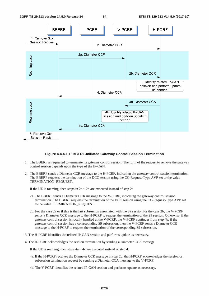
ETSI
ETSI TS 129 213 V14.5.0 (2017-10)643GPP TS 29.213 version 14.5.0 Release 14
Figure 4.4.4.1.1: BBERF-Initiated Gateway Control Session Termination
1. The BBERF is requested to terminate its gateway control session. The form of the request to remove the gateway control session depends upon the type of the IP-CAN.
2. The BBERF sends a Diameter CCR message to the H-PCRF, indicating the gateway control session termination. The BBERF requests the termination of the DCC session using the CC-Request-Type AVP set to the value TERMINATION_REQUEST.
If the UE is roaming, then steps in 2a ~ 2b are executed instead of step 2:
2a. The BBERF sends a Diameter CCR message to the V-PCRF, indicating the gateway control session termination. The BBERF requests the termination of the DCC session using the CC-Request-Type AVP set to the value TERMINATION_REQUEST.
2b. For the case 2a or if this is the last subsession associated with the S9 session for the case 2b, the V-PCRF sends a Diameter CCR message to the H-PCRF to request the termination of the S9 session. Otherwise, if the gateway control session is locally handled at the V-PCRF, the V-PCRF continues from step 4b; if the gateway control session has a corresponding S9 subsession, then the V-PCRF sends a Diameter CCR message to the H-PCRF to request the termination of the corresponding S9 subsession.
3. The H-PCRF identifies the related IP-CAN session and performs update as necessary.
4. The H-PCRF acknowledges the session termination by sending a Diameter CCA message.
If the UE is roaming, then steps 4a ~ 4c are executed instead of step 4:
4a. If the H-PCRF receives the Diameter CCR message in step 2b, the H-PCRF acknowledges the session or subsession termination request by sending a Diameter CCA message to the V-PCRF.
4b. The V-PCRF identifies the related IP-CAN session and performs update as necessary.

ETSI
ETSI TS 129 213 V14.5.0 (2017-10)653GPP TS 29.213 version 14.5.0 Release 14
4c. The V-PCRF acknowledges the session termination by sending a Diameter CCA message to the BBERF.
5. The BBERF sends a reply to the request to remove the gateway control session. The form of the reply depends upon the type of the IP-CAN.
4.4.4.2 PCRF-Initiated Gateway Control Session Termination
This procedure applies for case 2a, as defined in clause 4.0, when the PCRF detects that there is no remaining IP-CAN session at the PCRF.
BBERF
1. Remove Gxx
Session Request
2. Diameter RAR
PCEF V-PCRF H-PCRF
2a. Diameter RAR
2b. Diameter RAR
3. Diameter RAA
3b. Diameter RAA
3a. Diameter RAA
Roaming case
Roaming case
4. The BBERF terminates the Gateway control session based on the BBERF-
initiated termination procedures.
Figure 4.4.4.2.1: PCRF-Initiated Gateway Control Session Termination
1. The H-PCRF is requested to terminate the gateway control session.
2. The H-PCRF sends a Diameter RAR message to the BBERF including a Session-Release-Cause AVP to indicate request for terminating the gateway control session.
If the UE is roaming, then steps in 2a ~ 2b are executed instead of Step 2:
2a. The H-PCRF sends a Diameter RAR message to the V-PCRF to indicate the termination of the S9 session including the Session-Release-Cause AVP.
2b. The V-PCRF sends a Diameter RAR message to the BBERF based on the termination request received from the H-PCRF to indicate the gateway control session termination.
3. The BBERF acknowledges the gateway control session termination request by sending a Diameter RAA message.

ETSI
ETSI TS 129 213 V14.5.0 (2017-10)663GPP TS 29.213 version 14.5.0 Release 14
If the UE is roaming, then steps 3a ~ 3b are executed instead of Step 3:
3a. The BBERF acknowledges the gateway control session termination request by sending a Diameter RAA message to the V-PCRF.
3b. The V-PCRF sends a Diameter RAA message to the H-PCRF and acknowledges the request for terminating the S9 session corresponding to the gateway control session.
4. The BBERF follows the BBERF-initiated gateway control session termination procedures described in clause 4.4.4.1 to terminate the gateway control session.
4.5 Multiple BBERF Signalling Flows
4.5.1 Non-Roaming and Home Routed cases
4.5.1.1 New Gateway Control Session Establishment
The following signalling flow describes an example of a new BBERF initiating a GW control session establishment associated with an existing IP-CAN session.

ETSI
ETSI TS 129 213 V14.5.0 (2017-10)673GPP TS 29.213 version 14.5.0 Release 14
H-PCRF Target BBERF
7. Diameter CCA
3. Store Information
6. Store PCC/QoS Rules
1. Establish Gateway Control Session Request
9. Establish Gateway Control Session Response
Legend:
Mandatory
Conditional
V-PCRF
2b. Store Information and identify home routed access
Source BBERF
7b. Store PCC/QoS Rules. Policy decision
7e. Diameter CCA
RO
AM
ING
CA
SE
2c. Diameter CCR
2. Diameter CCR
7c. Diameter CCR
7d. Diameter CCA
2a. Diameter CCR
RO
AM
ING
CA
SE
7a. Diameter CCA
PCEF
8. Install QoS Rules. Policy enforcement
4. Identify multiple BBERF(s)
5. PCC/QoS Rules decision based on BCM of GW control session
Figure 4.5.1.1.1: Gateway Control Session Establishment during BBERF relocation
1. The target BBERF receives a message or indication to establish a Gateway Control session
2. The target BBERF initiates a Gateway Control session with the H-PCRF by sending a CCR using the CC-Request-Type AVP set to the value INITIAL_REQUEST to the H-PCRF. The target BBERF provides information as detailed in clause 4a.5.1 of 3GPP TS 29.212 [9].
When the UE is roaming, the following steps are executed instead of step 2:
2a. The target BBERF initiates a Gateway Control session with the V-PCRF by sending a CCR using the CC-Request-Type AVP set to the value INITIAL_REQUEST to the V-PCRF. The target BBERF provides information as detailed in clause 4a.5.1 of 3GPP TS 29.212 [9].
ETSI
ETSI TS 129 213 V14.5.0 (2017-10)683GPP TS 29.213 version 14.5.0 Release 14
2b. The V-PCRF determines based on the UE identity information that the request is for a roaming user. The V-PCRF checks whether the V-PCRF is required to send the request to the H-PCRF based on the roaming agreements.
2c. For case 2a:
- The V-PCRF sends a CCR to the H-PCRF with the CC-Request-Type AVP set to the value UPDATE_REQUEST. The V-PCRF includes in the CCR the information received in step 2a. The V-PCRF includes the BBERF identity by including the AN-GW-Address AVP at command level.
For case 2b:
- If the Session-Linking-Indicator AVP is not received, or it indicates SESSION_LINKING_IMMEDIATE, the V-PCRF sends the CCR command to the H-PCRF with the CC-Request-Type AVP set to the value UPDATE_REQUEST. The V-PCRF includes the Subsession-Enforcement-Info AVP within the CCR command with allocated S9 subsession identifier assigned by the V-PCRF for this PDN connection within the Subsession-Id AVP, the Subsession-Operation AVP set to the value MODIFICATION, the BBERF identity within AN-GW-Address AVP.
- If the Session-Linking-Indicator AVP is received indicating that the session linking has to be deferred, the V-PCRF sends a CCR to the H-PCRF with the CC-Request-Type AVP set to the value UPDATE_REQUEST. The V-PCRF includes the Subsession-Enforcement-Info AVP within the CCR with a new S9 subsession identifier assigned by the V-PCRF to this Gateway Control Session within the Subsession-Id AVP, the Subsession-Operation AVP set to the value ESTABLISHMENT and the Session-Linking-Indicator AVP set to the value “SESSION_LINKING_DEFERRED”.
3. The H-PCRF stores the information received in the Diameter CCR.
4. If the Session-Linking-Indicator AVP was received indicating that the session linking has to be deferred, the linking between the Gateway Control Session and the Gx session shall be deferred. Otherwise, based on the information received the H-PCRF identifies multiple BBERF sessions for a particular IP-CAN session.
5. The H-PCRF derives applicable PCC/QoS rules based on the BCM mode as defined in clause 4a.5.7 of 3GPP TS 29.212 [9].
6. The H-PCRF stores the selected QoS Rules and PCC Rules. For non-roaming users the H-PCRF selects the Bearer Control Mode that will apply during the Gateway Control session.
7. The H-PCRF acknowledges the Gateway Control Session by sending a Diameter CCA. The H-PCRF includes the selected BCM if applicable, the QoS rules and event triggers.
When the UE is roaming, the following steps are executed instead of step 7:
7a. The H-PCRF acknowledges the Gateway Control Session by sending a Diameter CCA to the V-PCRF. The H-PCRF includes applicable QoS rules and also event triggers. The H-PCRF also includes the AN-GW-Address AVP if the QoS rules are applicable for a single BBERF.
7b. The V-PCRF enforces visited operator policies regarding QoS authorization requested by the H-PCRF as indicated by the roaming agreements.
7c. If the V-PCRF denies an authorization, it informs the H-PCRF and may provide the acceptable QoS Information for the service.
7d. The H-PCRF may provide new or modified QoS rules to the V-PCRF.
7e. The V-PCRF acknowledges the Gateway Control Session and provisions, when applicable, the selected BCM, policy decisions and event triggers to the target BBERF.
8. The BBERF installs the received QoS Rules.
9. The target BBERF establishes an indication for a Gateway control session response.

ETSI
ETSI TS 129 213 V14.5.0 (2017-10)693GPP TS 29.213 version 14.5.0 Release 14
4.5.1.2 PCEF IP-CAN session modification – Handover
The following signalling flow describe the case when an indication of handover is received by the PCEF and the H-PCRF derives QoS rules based on the type of BBERF (primary/non-primary).
H-PCRF Target BBERF
7. Diameter CCA
3. Store Information
6. Store PCC/QoS Rules
1. Indication of handover
Legend:
Mandatory
Conditional
V-PCRF Source BBERF
8b. Store PCC/QoS Rules. Policy decision
8e. Diameter RAR
2. Diameter CCR
8c. Diameter RAA
8d. Diameter RAR
RO
AM
ING
CA
SE
8a. Diameter RAR
PCEF
9. Install QoS Rules. Policy enforcement
4. Derive primary/non-primary BBERF(s)
5. PCC/QoS Rules decision based on BCM of GW control session
8. Diameter RAR
10a. Diameter RAA
10b. Diameter RAA
10. Diameter RAA
RO
AM
ING
CA
SE
Figure 4.5.1.2.1: PCEF IP-CAN session modification – Handover
1. The PCEF receives a message or indication that a handover occurred
2. The PCEF initiates an IP-CAN Session Modification procedure by sending a CCR using the CC-Request-Type AVP set to the value UPDATE_REQUEST to the H-PCRF. The PCEF includes the AN_GW_CHANGE event trigger, and if applicable the IP-CAN_CHANGE event trigger as well, to indicate that handover has occurred.
3. The H-PCRF stores the information received in the Diameter CCR.
4. If there is a pending gateway control session to be linked to a Gx session, the H-PCRF shall perform the session linking according to clause 4a.5.6 of 3GPP TS 29.212 [9] for the non-roaming case. Based on the information received the H-PCRF reclassifies primary/non-primary BBERFs according to the procedures defined in clause 4a.5.7 of 3GPP TS 29.212 [9].

ETSI
ETSI TS 129 213 V14.5.0 (2017-10)703GPP TS 29.213 version 14.5.0 Release 14
5. The H-PCRF derives PCC rules for the PCEF, and QoS rules for the new reclassified primary BBERF, based on the BCM mode of the GW control session as defined in clause 4a.5.7 of 3GPP TS 29.212 [9].
6. The H-PCRF stores the selected QoS Rules and PCC Rules.
7. The H-PCRF acknowledges the IP-CAN session modification request by sending a Diameter CCA to the PCEF. The H-PCRF includes updated PCC rules and event triggers (if applicable).
8. The H-PCRF initiates a Gateway Control and QoS Rules Provision procedure by sending a Diameter RAR. The H-PCRF includes the selected BCM if applicable, the QoS rules and event triggers.
When the UE is roaming, the following steps are executed instead of step 8:
8a. The H-PCRF initiates a Gateway Control and QoS Rules Provision procedure to the V-PCRF by sending a Diameter RAR to the V-PCRF. The H-PCRF sends applicable QoS rules based on the BBERF type (primary/non-primary) and BCM mode selected as defined in clause 4a.5.9 of 3GPP TS 29.212 [9]. The H-PCRF includes the AN-GW-Address AVP if the QoS rules are applicable only for a single BBERF. If the QoS rules are applicable for all BBERF sessions this AVP is omitted.
8b. The V-PCRF enforces visited operator policies regarding QoS authorization requested by the H-PCRF as indicated by the roaming agreements.
8c. If the V-PCRF denies an authorization, it informs the H-PCRF and may provide the acceptable QoS Information for the service by including in the RAA command the QoS-Rule-Report AVP to indicate the QoS Rules that were not accepted, the Rule-Failure-Code AVP set to UNSUCCESSFUL-QoS-VALIDATION, and the QoS-Information AVP.
8d. The H-PCRF may provide new or modified QoS rules to the V-PCRF.
8e. The V-PCRF initiates the Gateway Control Session and QoS rules provisions, when applicable, the selected BCM, policy decisions and event triggers to the target BBERF.
9. The BBERF installs the received QoS Rules.
10. The target BBERF acknowledges the RAR command by sending a Diameter RAA command to the PCRF.
When the UE is roaming, the following steps are executed instead of step 10:
10a.The BBERF acknowledges the Gateway Control and QoS Rules Provision request by sending a Diameter RAA to the V-PCRF.
10b. The V-PCRF acknowledges the Gateway Control and QoS Rules Provision request by sending a Diameter RAA to the H-PCRF.
4.5.1.3 PCEF IP-CAN session modification – S2c-based IP flow mobility
The following signalling flow describes an example of S2c-based IP flow mobility. In this case, the H-PCRF receives an IP flow mobility event by the PCEF and derives QoS rules based on the IP flow mobility routing rules.

ETSI
ETSI TS 129 213 V14.5.0 (2017-10)713GPP TS 29.213 version 14.5.0 Release 14
H-PCRF BBERF #2
6. Diameter CCA
3. Store Information
5. Store PCC/QoS Rules
1. Ind ication of IP flow mobility
Legend:
Mandatory
Conditional
V-PCRF BBERF #1
7b. Store PCC/QoS Rules. Policy decision
7e. Diameter RAR
2. Diameter CCR
7c. Diameter RAA
7d. Diameter RAR RO
AM
ING
CA
SE
7a. Diameter RAR
PCEF
8. Perform Step 9-10b: as specified in Figure 4.5.1.2.1: PCEF-in itiated IP-CAN session modification – Handover.
4. PCC/QoS Rules decision based on BCM of GW control session and received IP flow mobility routing rules
7. Diameter RAR
Figure 4.5.1.3.1: PCEF IP-CAN session modification – S2c-based IP flow mobility
1. The PCEF receives a message or indication that an IP flow mobility event occurred
2. The PCEF initiates an IP-CAN Session Modification procedure by sending a CCR using the CC-Request-Type AVP set to the value UPDATE_REQUEST to the H-PCRF. The PCEF includes the ROUTING_RULE_CHANGE event trigger to indicate that a change in the IP flow mobility routing rules has occurred. The PCEF includes in the CCR the Routing-Rule-Install and/or Routing-Rule-Removal AVPs.
3. The H-PCRF stores the information received in the Diameter CCR.
4. The H-PCRF derives PCC rules for the PCEF, and QoS rules for the BBERF(s), based on the BCM mode of the GW control session and the IP flow mobility routing rules as defined in clause 4a.5.7 of 3GPP TS 29.212 [9]
5. The H-PCRF stores the selected PCC/QoS Rules.
6. The H-PCRF acknowledges the IP-CAN session modification request by sending a Diameter CCA to the PCEF. The H-PCRF includes updated PCC rules and event triggers (if applicable).
7. The H-PCRF initiates a Gateway Control and QoS Rules Provision procedure by sending a Diameter RAR. The H-PCRF includes the QoS rules and event triggers.
When the UE is roaming, the following steps are executed instead of step 7:
7a. The H-PCRF initiates a Gateway Control and QoS Rules Provision procedure to the V-PCRF by sending a Diameter RAR to the V-PCRF. The H-PCRF sends applicable QoS rules based on BCM mode selected as defined in clause 4a.5.9 of 3GPP TS 29.212 [9]. The H-PCRF includes the AN-GW-Address AVP identifying the BBERF involved in the exchange of the IP flows described by the received IP flow mobility routing rules

ETSI
ETSI TS 129 213 V14.5.0 (2017-10)723GPP TS 29.213 version 14.5.0 Release 14
7b. The V-PCRF enforces visited operator policies regarding QoS authorization requested by the H-PCRF as indicated by the roaming agreements.
7c. If the V-PCRF denies an authorization, it informs the H-PCRF and may provide the acceptable QoS Information for the service by including in the RAA command the QoS-Rule-Report AVP to indicate the QoS Rules that were not accepted, the Rule-Failure-Code AVP set to UNSUCCESSFUL-QoS-VALIDATION, and the QoS-Information AVP.
7d. The H-PCRF may provide new or modified QoS rules to the V-PCRF.
7e. The V-PCRF initiates the Gateway Control Session and QoS rules provisions, when applicable, policy decisions and event triggers to BBERF.
8 Step 9 through step 10b: as specified in Figure 4.5.1.2.1: PCEF-initiated IP-CAN session modification- Handover are executed, as needed. If the IP flows were moved from one access to another (e.g. 3GPP to WLAN, or vice versa), the PCRF may also initiate a RAR command towards BBERF#1 to modify or release the related resources associated with the flows that were moved to BBERF#2.
4.5.1.4 Gateway Control Session Establishment and PCEF IP-CAN session modification – S2c-based IP flow mobility
The following signalling flow describes an example of S2c-based IP flow mobility. In this case, the H-PCRF receives a Gateway Control session establishment by a BBERF and an IP flow mobility event by the PCEF. H-PCRF associates the IP-CAN session to multiple Gateway Control Sessions and derives QoS rules based on the IP flow mobility routing rules.
H-PCRF BBERF #2
4. Store Information.
2. Ind ication of IP flow mobility
Legend:
Mandatory
V-PCRF BBERF #1
3. Diameter CCR
PCEF
5. PCC/QoS Rules decision based on BCM of GW control session and received IP flow mobility routing rules
1. Perform Step 1-10: as specified in Figure Figure 4.4.1.1 Gateway Control Session Establishment.
6. Perform Step 5-8: as specified in Figure 4.5.1.x.1: PCEF-initiated IP-CAN session modification – IP Flow mobility.
Figure 4.5.1.4.1: Gateway Control Session Establishment and PCEF IP-CAN session modification – S2c-based IP flow mobility
1. Step 1 through step 10: as specified in Figure 4.4.1.1: Gateway Control Session Establishment are executed, as needed. The Gateway Control Session is established for BBERF #2. The Gateway Control Session for BBERF #1 was previously established.

ETSI
ETSI TS 129 213 V14.5.0 (2017-10)733GPP TS 29.213 version 14.5.0 Release 14
NOTE: If the Gateway Control Session is established for WLAN access, only case 2a is possible.
2. The PCEF receives a message or indication that an IP flow mobility event occurred.
3. The PCEF initiates an IP-CAN Session Modification procedure by sending a CCR using the CC-Request-Type AVP set to the value UPDATE_REQUEST to the H-PCRF. The PCEF includes the ROUTING_RULE_CHANGE event trigger to indicate that a change in the IP flow mobility routing rules has occurred. The PCEF includes in the CCR the Routing-Rule-Install and/or Routing-Rule-Removal AVPs.
4. The H-PCRF stores the information received in the Diameter CCR.
5. The H-PCRF does not differentiate between primary and non-primary BBFs. H-PCRF derives PCC rules for the PCEF, and QoS rules for the BBERF(s), based on the BCM mode of the GW control session and the IP flow mobility routing rules as defined in clause 4a.5.7 of 3GPP TS 29.212 [9]
6. Step 5 through step 8: as specified in Figure 4.5.1.3.1: PCEF-initiated IP-CAN session modification- IP Flow mobility are executed, as needed.
4.5.2 Visited access case
4.5.2.1 New Gateway Control Session Establishment
The following signalling flow describes an example of a new BBERF initiating a GW control session establishment associated with an existing IP-CAN session.

ETSI
ETSI TS 129 213 V14.5.0 (2017-10)743GPP TS 29.213 version 14.5.0 Release 14
H-PCRF Target BBERF
1. Establish Gateway Control Session Request
V-PCRF
3. Store Information and identify visited access
Source BBERF
2. Diameter CCR
PCEF
4. Identify multiple BBERF(s). Derive and Store QoS Rules. Policy decision
RO
AM
ING
CA
SE
(V
isite
d a
cce
ss)
5. Diameter CCR
7. Diameter CC A
6. Store Information, PCC Rules decision and store
11. Establish Gateway Control Session Response
9. Diameter CCA
10. Install QoS Rules. Policy enforcement
8. Store PCC/QoS Rules. Policy decision
8a. Diameter CCR
8b. Diameter CC A
Figure 4.5.2.1.1: Gateway Control Session Establishment during BBERF relocation
1. The target BBERF receives a message or indication to establish a Gateway Control Session.
2. The target BBERF initiates a Gateway Control Session with the V-PCRF by sending a CCR using the CC-Request-Type AVP set to the value INITIAL_REQUEST to the V-PCRF. The target BBERF provides information as detailed in clause 4a.5.1 of 3GPP TS 29.212 [9].
3. The V-PCRF stores the information received in the Diameter CCR and determines based on the UE identity information that the request is for a roaming user. The V-PCRF checks whether the V-PCRF is required to send the request to the H-PCRF based on the roaming agreements. The V-PCRF does not send the CCR to the H-PCRF to update the S9 session immediately if the Session-Linking-Indicator AVP was received indicating that the session linking has to be deferred.
4. If the Session-Linking-Indicator AVP was received indicating that the session linking has to be deferred, the linking between the Gateway Control Session and the Gx session shall be deferred. Otherwise, based on the information received the V-PCRF identifies multiple BBERF sessions for a particular IP-CAN session. The V-PCRF derives applicable QoS rules according to local policies and stores them.
For case 2a or if either the AN_GW_CHANGE or the IP-CAN_CHANGE event is subscribed by H-PCRF and this event trigger is received steps 5~8 are executed. Otherwise steps 5~8 are skipped.

ETSI
ETSI TS 129 213 V14.5.0 (2017-10)753GPP TS 29.213 version 14.5.0 Release 14
5. The V-PCRF initiates an IP-CAN Session Modification procedure by sending a CCR to the H-PCRF with the CC-Request-Type AVP set to the value UPDATE_REQUEST. The V-PCRF includes in the CCR the information received in step 2.
6. The H-PCRF stores the information received in the Diameter CCR. And the H-PCRF decides PCC rules for the BBERF and stores PCC rules.
7. The H-PCRF sends a Diameter CCA to the V-PCRF to provide the PCC rules. The H-PCRF sends applicable PCC rules. The H-PCRF includes the AN-GW-Address AVP if the PCC rules are applicable only for a single BBERF. If the PCC rules are applicable for all BBERF sessions this AVP is omitted.
8. If the steps 5~7 are executed, the V-PCRF enforces visited operator policies regarding QoS authorization requested by the H-PCRF as indicated by the roaming agreements.
Steps 8a and 8b are executed if the V-PCRF denies authorisation for one or more PCC rules.
8a. If V-PCRF denies authorization, it informs the H-PCRF by sending a CCR command including the Charging-Rule-Report AVP to indicate the PCC Rules that were not accepted, the Rule-Failure-Code AVP set to UNSUCCESSFUL-QoS-VALIDATION, and the acceptable QoS Information for the service.
8b. The H-PCRF may provide new modified PCC rules to the V-PCRF.
9. The V-PCRF acknowledges the Gateway Control Session and provisions policy decisions and event triggers to the target BBERF.
10. The BBERF installs the received QoS rules.
11. The target BBERF responds to the Gateway control session establishment request in step 1.
4.5.2.2 PCEF-Initiated IP-CAN session modification-Handover
The following signalling flow describe the case when an indication of handover is received by the PCEF and the H-PCRF derives QoS rules based on the type of BBERF (primary/non-primary)

ETSI
ETSI TS 129 213 V14.5.0 (2017-10)763GPP TS 29.213 version 14.5.0 Release 14
H-PCRF Target BBERF
7. Store Information
1. Indication of handover
Legend:
Mandatory
Conditional
V-PCRF Source BBERF
10. Store PCC/QoS Rules. Policy decision
12. Diameter RAR
2. Diameter CCR
RO
AM
ING
CA
SE
(
Vis
ited
acc
ess
)
9. Diameter CC A
PCEF
13. Install QoS Rules Policy enforcement
5. Derive primary/non-primary BBERF(s)
8. PCC Rules decision and store
14. Diameter RAA
3. Store Information
6. Diameter CCR
11 Diameter CCA
4. Identify multiple BBERF(s)
10a. Diameter CCR
10b. Diameter CC A
Figure 4.5.2.2.1: PCEF-initiated IP-CAN session modification – Handover
1. The PCEF receives a message or indication that a handover occurred.
2. The PCEF initiates an IP-CAN Session Modification procedure by sending a CCR using the CC-Request-Type AVP set to the value UPDATE_REQUEST to the V-PCRF. The PCEF includes the AN_GW_CHANGE event trigger, and if applicable the IP-CAN_CHANGE event trigger as well, to indicate that handover has occurred.
3. The V-PCRF stores the information received in the Diameter CCR.
4. If there is a pending Gateway Control Session to be linked to a Gx session, the V-PCRF links Gateway Control Session with the Gx session according to clause 4a.5.6 of 3GPP TS 29.212 [9]. Otherwise based on the information received the V-PCRF identifies multiple BBERF sessions for a particular IP-CAN session.
5. Based on the information received the V-PCRF reclassifies primary/non-primary BBERFs according to the procedures defined in clause 4a.5.7 of 3GPP TS 29.212 [9].

ETSI
ETSI TS 129 213 V14.5.0 (2017-10)773GPP TS 29.213 version 14.5.0 Release 14
If either the AN_GW_CHANGE or the IP-CAN_CHANGE event is subscribed by H-PCRF and this event trigger is received steps 6~9 are executed. Otherwise steps 6~9 are skipped.
6. The V-PCRF initiates an IP-CAN Session Modification procedure by sending a CCR to the H-PCRF with the CC-Request-Type AVP set to the value UPDATE_REQUEST. The V-PCRF includes in the CCR the information received in step 2.
7. The H-PCRF stores the information received in the Diameter CCR.
8. The H-PCRF decides PCC rules for the PCEF and stores PCC rules.
9. The H-PCRF sends a Diameter CCA to the V-PCRF to provide the PCC Rules. The H-PCRF sends applicable PCC rules. The H-PCRF includes the AN-GW-Address AVP if the PCC rules are applicable only for a single BBERF. If the PCC rules are applicable for all BBERF sessions this AVP is omitted.
10. If the steps 6~9 are executed, the V-PCRF enforces visited operator policies regarding QoS authorization requested by the H-PCRF as indicated by the roaming agreements.
Steps 10a and 10b are executed if the V-PCRF denies authorisation for one or more PCC rules.
10a. If V-PCRF denies authorization, it informs the H-PCRF by sending a CCR command including the Charging-Rule-Report AVP to indicate the PCC Rules that were not accepted, the Rule-Failure-Code AVP set to UNSUCCESSFUL-QoS-VALIDATION, and the acceptable QoS Information for the service.
10b. The H-PCRF may provide new modified PCC rules to the V-PCRF.
11. The V-PCRF acknowledges the IP-CAN session modification request by sending a Diameter CCA to the PCEF. The V-PCRF includes updated PCC rules and event triggers (if applicable)
12. The V-PCRF initiates the Gateway Control Session and QoS rules provisions by sending a Diameter RAR to the BBERF policy decisions and event triggers to the target BBERF.
13. The BBERF installs the received QoS Rules.
14. The BBERF acknowledges the Gateway Control and QoS Rules Provision request by sending a Diameter RAA to the V-PCRF.
4.5.2.3 PCEF-Initiated IP-CAN session modification - S2c-based IP flow mobility
The following signalling flow describes an example of S2c-based IP flow mobility. In this case, the H-PCRF receives an IP flow mobility event by the PCEF and derives QoS rules based on the IP flow mobility routing rules.

ETSI
ETSI TS 129 213 V14.5.0 (2017-10)783GPP TS 29.213 version 14.5.0 Release 14
H-PCRF BBERF #2
6. Store Information
1. Ind ication of IP flow mobility
Legend:
Mandatory
Conditional
V-PCRF BBERF #1
10. Perform Step 11-14: as specified in Figure 4.5.2.2.1: PCEF-initiated IP-CAN session modification – Handover.
2. Diameter CCR
RO
AM
ING
CA
SE
(
Vis
ited
acce
ss
)
PCEF
7. PCC Rules decision and store
3. Store Information
4. Change in IP flow mobility routing rules
9. Extract QoS Rules based on PCC rules and IP flow mobility rules
5. Diameter CCR
8. Diameter CCA
9a . Diameter CCR
9b . Diameter CCA
Figure 4.5.2.3.1: PCEF-initiated IP-CAN session modification – S2c-based IP flow mobility
1. The PCEF receives a message or indication that a handover occurred.
2. The PCEF initiates an IP-CAN Session Modification procedure by sending a CCR using the CC-Request-Type AVP set to the value UPDATE_REQUEST to the V-PCRF. The PCEF includes the ROUTING_RULE_CHANGE event trigger to indicate that a change in the IP flow mobility routing rules has occurred. The PCEF includes in the CCR Routing-Rule-Install and/or Routing-Rule-Removal AVPs.
3. The V-PCRF stores the information received in the Diameter CCR.
4. Based on the information received the V-PCRF determines that there is a change in the IP flow routing in the multiple BBERF(s) as described in clause 4a.5.7 of 3GPP TS 29.212 [9].
If either the AN_GW_CHANGE or the IP-CAN_CHANGE event is subscribed by H-PCRF and this event trigger is received steps 5~8 are executed. Otherwise steps 5~8 are skipped.
5. The V-PCRF initiates an IP-CAN Session Modification procedure by sending a CCR to the H-PCRF with the CC-Request-Type AVP set to the value UPDATE_REQUEST. The V-PCRF includes in the CCR the information received in step 2.
6. The H-PCRF stores the information received in the Diameter CCR.

ETSI
ETSI TS 129 213 V14.5.0 (2017-10)793GPP TS 29.213 version 14.5.0 Release 14
7. The H-PCRF decides PCC rules for the PCEF and stores PCC rules. Based on the IP flow mobility routing rule as defined in clause 4a.5.7 of 3GPP TS 29.212 [9]
8. The H-PCRF sends a Diameter CCA to the V-PCRF to provide the PCC Rules. The H-PCRF sends applicable PCC rules.
9. If the steps 5~8 are executed, the V-PCRF establishes QoS Rules based on received IP flow mobility routing rules and enforces visited operator policies regarding QoS authorization requested by the H-PCRF as indicated by the roaming agreements.
Steps 9a and 9b are executed if the V-PCRF denies authorisation for one or more PCC rules.
9a. If V-PCRF denies authorization, it informs the H-PCRF by sending a CCR command including the Charging-Rule-Report AVP to indicate the PCC Rules that were not accepted, the Rule-Failure-Code AVP set to UNSUCCESSFUL-QoS-VALIDATION, and the acceptable QoS Information for the service.
9b. The H-PCRF may provide new modified PCC rules to the V-PCRF.
10. Step 11 through step 14: as specified in Figure 4.5.2.2.1: PCEF-initiated IP-CAN session modification- Handover are executed, as needed. If the IP flows were moved from one access to another (e.g. 3GPP to WLAN, or vice versa), the PCRF may also initiate a RAR command towards BBERF#1 to modify or release the related resources associated with the flows that were moved to BBERF#2.
4.5.2.4 Gateway Control Session Establishment and PCEF IP-CAN session modification – S2c-based IP flow mobility
The following signalling flow describes an example of IP flow mobility. In this case, the V-PCRF receives a Gateway Control session establishment by a BBERF and an IP flow mobility event by the PCEF. V-PCRF associates the IP-CAN session to multiple Gateway Control Sessions and derives QoS rules based on the IP flow mobility routing rules.

ETSI
ETSI TS 129 213 V14.5.0 (2017-10)803GPP TS 29.213 version 14.5.0 Release 14
H-PCRF BBERF #2
2. Ind ication of IP flow mobility
V-PCRF BBERF #1
10. Perform Step 9-10: as specified in Figure 4.5.2.x.1: PCEF-initiated IP-CAN session modification – IP flow mobility.
3. Diameter CCR
RO
AM
ING
CA
SE
(
Vis
ited
acce
ss
)
PCEF
4. Store Information
5. Evaluates IP flow mobility routing rules
1. Perform Step 1-10: as specified in Figure Figure 4.4.1.1 Gateway Control Session Establishment.
7. Store Information
8. PCC Rules decision and store
6. Diameter CCR
9. Diameter CCA
Legend:
Mandatory
Conditional
Figure 4.5.2.4.1: Gateway Control Session Establishment and PCEF IP-CAN session modification – S2c-based IP flow mobility
1. Step 1 through step 10: as specified in Figure 4.4.1.1: Gateway Control Session Establishment are executed, as needed. The Gateway Control Session is established for BBERF #2. The Gateway Control Session for BBERF #1 was previously established.
NOTE: If the Gateway Control Session is established for WLAN access, only case 2a is possible.
2. The PCEF receives a message or indication that an IP flow mobility event occurred.
3. The PCEF initiates an IP-CAN Session Modification procedure by sending a CCR using the CC-Request-Type AVP set to the value UPDATE_REQUEST to the V-PCRF. The PCEF includes the ROUTING_RULE_CHANGE event trigger to indicate that a change in the IP flow mobility routing rules has occurred. The PCEF includes in the CCR Routing-Rule-Install and/or Routing-Rule-Removal AVPs.
4. The V-PCRF stores the information received in the Diameter CCR.
5. Based on the received information, the V-PCRF does not differentiate between primary and non-primary BBFs and determines that there are IP flows routed through multiple BBERF(s) as described in clause 4a.5.7 of 3GPP TS 29.212 [9].
If either the AN_GW_CHANGE or the IP-CAN_CHANGE event is subscribed by H-PCRF and this event trigger is received steps 6~9 are executed. Otherwise steps 6~9 are skipped.

ETSI
ETSI TS 129 213 V14.5.0 (2017-10)813GPP TS 29.213 version 14.5.0 Release 14
6. The V-PCRF initiates an IP-CAN Session Modification procedure by sending a CCR to the H-PCRF with the CC-Request-Type AVP set to the value UPDATE_REQUEST. The V-PCRF includes in the CCR the information received in step 2.
7. The H-PCRF stores the information received in the Diameter CCR.
8. The H-PCRF decides PCC rules for the PCEF and stores PCC rules. Based on the IP flow mobility routing rule as defined in clause 4a.5.7 of 3GPP TS 29.212 [9].
9. The H-PCRF sends a Diameter CCA to the V-PCRF to provide the PCC Rules. The H-PCRF sends applicable PCC rules.
10. Step 9 through step 10: as specified in Figure 4.5.2.3.1: PCEF-initiated IP-CAN session modification- IPFlow mobility are executed, as needed.
4.6 Application Detection and Enforcement Procedures
4.6.1 TDF Session Establishment in case of solicited reporting
In the following procedure, the PCRF is the H-PCRF for the roaming UE with home routed access and the V-PCRF for the roaming UE with visited access.
As part of the IP-CAN Session Establishment or Modification procedure, in case of solicited application reporting with a TDF, the PCRF initiates a TDF Session Establishment with the selected TDF. The TDF is selected based on data received from the PCEF or a local configuration at the PCRF.
Figure 4.6.1.1: TDF Session Establishment in case of solicited reporting
1. PCRF initiates a session towards the TDF. The PCRF provisions the applicable ADC Rules for the corresponding TDF session by sending a Diameter TS-Request to the TDF, including user identity information, the UE Ipv4 address and/or UE Ipv6 prefix and, if available, PDN identifier, IP-CAN type, RAT type and additional parameters as defined in clause 4b.5.1.1 of 3GPP TS 29.212 [9]. PCRF may also subscribe to the Event Triggers (e.g. APPLICATION_START and APPLICATION_STOP).
NOTE: For PDN type Ipv4v6, in case the UE Ipv4 address is not available in the PCRF, the PCRF initiates the TDF session establishment providing the UE Ipv6 prefix, and will subsequently provide UE Ipv4 address to the TDF using Event-Report-Indication AVP to the TDF.
1a. This step applies to the IP-CAN Session Establishment procedure. If online charging is applicable for the TDF, and at least one ADC rule with charging parameters was activated, then the TDF requests credit information from the OCS over the Gyn interface. If the TDF receives credit re-authorisation triggers from

ETSI
ETSI TS 129 213 V14.5.0 (2017-10)823GPP TS 29.213 version 14.5.0 Release 14
the OCS then it requests the PCRF via a TSA message to provision the triggers at the PCEF and/or BBERF. The triggers to be provisioned are specified in the Event-Report-Indication AVP in the TSA message.
2. The TDF acknowledges the session establishment by sending a Diameter TS-Answer. The TDF may include Event-Report-Indication in the response.
4.6.1A TDF Session Establishment in case of unsolicited reporting
In the following procedure, the PCRF is the H-PCRF for the roaming UE with home routed access and the V-PCRF for the roaming UE with visited access.
When the TDF detects for an Ipv4 address or Ipv6 address the first application start, the TDF shall initiate the TDF Session Establishment procedure with the PCRF.
PCRF TDF
1. Diameter CCR
2. Diameter CCA
Figure 4.6.1A.1: TDF Session Establishment in case of unsolicited reporting
1. The TDF initiates a session by sending a CCR to the PCRF using the CC-Request-Type AVP set to the value INITIAL_REQUEST. The TDF provides the full UE IP address using either Framed-IP-Address AVP or Framed-Ipv6-Prefix AVP and, if available, the PDN identifier. The TDF also includes the TDF-Application-Identifier AVP, the Flow-Information AVP of the detected application when service data flow descriptions are deducible, within the Application-Detection-Information AVP and sets the event trigger value with APPLICATION_START. If Flow-Information AVP is included, the TDF-Application-Instance-Identifier shall also be included within the Application-Detection-Information AVP in order to allow correlation of APPLICATION_START.
2 The PCRF stores the information and acknowledges the session establishment by sending a CCA. The PCRF may include the Ipv6 prefix within the Framed-Ipv6-Prefix AVP if the established TDF session is Ipv6 address related.
NOTE 1: The TDF handles each Ipv4 address and Ipv6 prefix within a separate TDF session.
NOTE 2: In the scenario where the TDF performs initial Application Detection on 82vailabi simultaneous traffic flows for the same Ipv6 prefix (i.e. two or more from Ipv6 addresses of the same IP-CAN session) the TDF could not be aware that those flows belong to the same IP-CAN session until a response is received from the PCRF, containing the Ipv6 prefix. This leads to using separate TDF sessions for the Ipv6 addresses for the same IP-CAN session. The TDF reports new application detection information related to that Ipv6 prefix via any of the TDF sessions at a later stage.
4.6.2 TDF Session termination
In the following procedures, the PCRF is the H-PCRF for the roaming UE with home routed access and the V-PCRF for the roaming UE with visited access.
This procedure applies in any of the following cases:
- the corresponding IP-CAN session is terminated;

ETSI
ETSI TS 129 213 V14.5.0 (2017-10)833GPP TS 29.213 version 14.5.0 Release 14
- the Ipv4 address of a dual stack IP-CAN session is released and there is an active Ipv4 address related TDF session for the IP-CAN session (only for unsolicited application reporting);
- at any point of time when the PCRF decides that the session with TDF is to be terminated (e.g. subscriber profile changes).
Figure 4.6.2.1: TDF Session Termination
1. The PCRF sends a RAR including the Session-Release-Cause AVP to request that the TDF terminates the TDF session.
2. For the solicited application reporting, the TDF removes/deactivates all the ADC Rules which are applied to the TDF session.
3. The TDF sends a RAA to acknowledge the RAR.
4. The TDF sends a CCR to the PCRF, indicating the TDF Session termination. The TDF requests the termination of the Sd session using the CC-Request-Type AVP set to the value TERMINATION_REQUEST. For solicited application reporting, if the usage monitoring is enabled, the TDF informs the PCRF about the resources that have been consumed by the user since the last report in the same request.
5. The PCRF acknowledges the TDF session termination by sending a CCA to the TDF.

ETSI
ETSI TS 129 213 V14.5.0 (2017-10)843GPP TS 29.213 version 14.5.0 Release 14
4.6.3 TDF Session modification
4.6.3.1 Application Detection, Reporting and Control Rules Request
In the following procedure, the PCRF is the H-PCRF for the roaming UE with home routed access and the V-PCRF for the roaming UE with visited access.
Figure 4.6.3.1.1 Application Detection, Reporting and Control Rules Request
1. TDF is triggered to report an event(s) (e.g. The TDF detects the start/stop of an application traffic that matches with one or more activated ADC rules that do not contain the Mute-Notification AVP) for a TDF session. For the start of traffic detection, in case the enforcement actions were provided as a part of ADC rules, the TDF enforces corresponding actions for solicited application reporting.
2. The TDF sends a Diameter CCR to the PCRF with the CC-Request-Type AVP set to the value UPDATE_REQUEST to report an event. For the start of traffic detection, if PCRF has previously subscribed to the APPLICATION_START/APPLICATION_STOP Event-Triggers, the TDF includes TDF-Application-
PCRFTDF
2. Diameter CCR
5. Installation, modification
and removal of the ADC
Rules.
4. Diameter CCA
1. Trigger to report the
events.
3. makes the ADC
decisions
3. Makes the PCC/QoS/ADC decisions

ETSI
ETSI TS 129 213 V14.5.0 (2017-10)853GPP TS 29.213 version 14.5.0 Release 14
Identifier AVP, the Flow-Information AVP of the detected application when service data flow descriptions are deducible, within the Application-Detection-Information AVP and sets the event trigger value with APPLICATION_START. If Flow-Information AVP is included, the TDF-Application-Instance-Identifier shall also be included within the Application-Detection-Information AVP in order to allow correlation of APPLICATION_START. For the stop of traffic detection, if PCRF has previously subscribed to the APPLICATION_START/APPLICATION_STOP Event-Triggers, the TDF includes TDF-Application-Identifier AVP, the TDF-Application-Instance-Identifier AVP, if provided in the report of the start of application traffic detection within the Application-Detection-Information AVP and sets the event trigger value with APPLICATION_STOP. For the solicited application reporting, if usage monitoring is enabled and the usage threshold is reached or the PCRF removes the last ADC rule applicable for certain monitoring key or disables usage monitoring or requests usage report, the TDF may inform the PCRF about the corresponding usage that have been consumed by the user since the last report.
3. The PCRF stores the information, received in the Diameter CCR and makes the PCC/QoS and – in the solicited reporting case – ADC decisions.
4. The PCRF acknowledges to the TDF by sending a Diameter CCA. For the solicited application reporting, the PCRF may provide a new ADC decisions by including the ADC-Rule-Install AVP and/or ADC-Rule-Remove AVP to the TDF within this acknowledge.
5. For the solicited application reporting, the TDF installs, modifies and removes the ADC rules according the new ADC decisions provided in step 4.
NOTE: If the installation or modification of one or more ADC rules fails, the TDF reports the failure to the PCRF as defined in clause 4b.5.5 of 3GPP TS 29.212 [9].
4.6.3.2 Application Detection and Control Rules Provision
In the following procedure, the PCRF is the H-PCRF for the roaming UE with home routed access and the V-PCRF for the roaming UE with visited access. This procedure is applicable only for the solicited application reporting.
Figure 4.6.3.2.1 Application Detection and Control Rules Provision
1. The PCRF receives an internal or external trigger (e.g. the subscriber’s profile configuration is changed) to update the ADC rule or notify the event occurred at the PCEF/BBERF for a TDF session.

ETSI
ETSI TS 129 213 V14.5.0 (2017-10)863GPP TS 29.213 version 14.5.0 Release 14
2. The PCRF sends a Diameter RAR to provide a new ADC decision by including the ADC-Rule-Install AVP and/or ADC-Rule-Remove AVP or notify the event occurred at the PCEF/BBERF by including the Event-Report-Indication AVP.
3. The TDF stores the information, received in the Diameter RAR. The TDF installs, modifies and removes the ADC rules according the new ADC decisions provided in step 2.
4. The TDF acknowledges to the PCRF by sending a Diameter RAA to inform the PCRF about the outcome of the actions related to the decision(s).
4.7 Spending limits Procedures over Sy reference point
4.7.1 Initial Spending Limit Report Request
In the following procedure, the signalling flow for the H-PCRF to request the status of the policy counters available at the OCS, and to subscribe to updates of these policy counters by the OCS. If the H-PCRF provides the list of policy counter identifier(s), the OCS returns the policy counter status per policy counter identifier provided by the PCRF. If the H-PCRF does not provide the list of policy counter identifier(s), the OCS returns the policy counter status for all policy counter identifier(s), which are available for this subscriber.
Figure 4.7.1: Initial Spending Limit Report Request
1. The H-PCRF retrieves subscription information that indicates that policy decisions depend on policy counter(s) held at the OCS and optionally the list of policy counter identifier(s).
2. The H-PCRF sends a Diameter SLR command if no Sy session yet has been established for this subscriber. The Diameter SLR command includes the Subscription-Id AVP (e.g. IMSI) and optionally the list of policy counter identifier(s) within Policy-Counter-Identifier AVPs. The request also includes the SL-Request-Type AVP which set to the value INITIAL_REQUEST (0).
3. The OCS sends a Diameter SLA command to the PCRF. The Diameter SLA includes a Policy-Counter-Status-Report AVP for each requested policy counter identifier containing the policy counter identifier and the current status value, optionally pending policy counter statuses with the activation times, and Result-Code AVP contains the result of the operation. When no policy counter identifier(s) was provided, the Diameter SLA includes a Policy-Counter-Status-Report AVP for all policy counter identifiers applicable to the subscriber. The OCS stores the H-PCRF’s subscription to changes in the status of all policy counter identifiers provided to the H-PCRF in the Diameter SLA.
4.7.2 Intermediate Spending Limit Report Request
This clause describes the signalling flow for the H-PCRF to request the status of additional policy counters available at the OCS or to remove the request for the status of policy counters available at OCS. If the H-PCRF provides the list of policy counter identifier(s), the OCS returns the policy counter status per policy counter identifier provided by the PCRF.

ETSI
ETSI TS 129 213 V14.5.0 (2017-10)873GPP TS 29.213 version 14.5.0 Release 14
Figure 4.7.2: Intermediate Spending Limit Report Request
1. The H-PCRF decides to modify the list of subscribed policy counters, e.g. PCRF determines that policy decisions depend on additional policy counter identifier(s) held at the OCS or that notifications of policy counter status changes for some policy counters are no longer required.
2. The H-PCRF sends a Diameter SLR command, optionally including the list of policy counter identifier(s) within Policy-Counter-Identifier(s) AVPs. The request also includes the SL-Request-Type AVP which set to the value INTERMEDIATE_REQUEST (1).
3. The OCS sends the Diameter SLA command to the PCRF including Policy-Counter-Status-Report AVP(s) containing the policy counter identifier, the current status value and optionally pending policy counter statuses with the activation times. Result-Code contains the result of the operation is also included in the response.
4. The PCRF makes the policy decision based on the information provided by the OCS.
4.7.3 Final Spending Limit Report Request
This clause describes the signalling flow for the H-PCRF to unsubscribe to any future updates of policy counters for a given subscriber by the OCS. It cancels the request for reporting the change of the status of the policy counters available at the OCS.
Figure 4.7.3: Final Spending Limit Report Request
1. The PCRF decides that policy decisions for a given user no longer depend on policy counter(s) to which the PCRF has existing subscriptions for status change notification.

ETSI
ETSI TS 129 213 V14.5.0 (2017-10)883GPP TS 29.213 version 14.5.0 Release 14
2. The H-PCRF sends the Diameter STR command to the OCS to cancel the notification request from the OCS on policy counter status. The request includes the Termination-Cause which contains the reason why the session was terminated set to “DIAMETER_LOGOUT”.
3. The OCS sends the Diameter STA command to the H-PCRF with Result-Code contains the result of the operation.
4.7.4 Spending Limit Report
This clause describes the signalling flow for the OCS to notify the changes of the status of a subscribed policy counter(s) available at the OCS for that subscriber. Alternatively, the signalling flow can be re-used by the OCS to provide one or more pending statuses for a subscribed policy counter together with the time that have to be applied.
Figure 4.7.4: Spending Limit Report
1. The OCS detects that status of a policy counter identifier(s) has changed and the PCRF requested notification of changes in the status of a policy counter(s). Alternatively, if the OCS detects a policy counter status will change at a future point in time, the OCS shall be able to instruct the PCRF to apply one or more pending statuses for a requested policy counter.
2. When the status of a specific policy counter changes, or the OCS detects that a policy counter status will change at a future point in time and decides to instruct the PCRF to apply one or more pending statuses for a requested policy counter, the OCS shall determine the Sy sessions impacted by the change (i.e. those Sy sessions that have subscribed to status change notifications for the changed policy counter) and send the Diameter SNR command to the PCRF associated with each affected Sy session including one Policy-Counter-Status-Report AVP. If several counters change status at the same time, the OCS may group the status change notifications into a single Spending Limit Report request to the PCRF by sending multiple Policy-Counter-Status-Report AVPs in the request.
NOTE: Sy session is per UE. And more than one Sy session will exist when the UE has IP-CAN session connection with more than one PCRF.
3. The H-PCRF acknowledges the request by sending a Diameter SNA command with a Result-Code AVP set to DIAMETER_SUCCESS and use the status of the received policy counter(s) as input to its policy decision to apply operator defined actions, e.g. downgrade the QoS. The PCRF shall ignore an unknown policy counter status report for all unknown policy counter identifiers in the SNR from the OCS.
4.8 Call flows for User Plane Congestion Management
4.8.1 General
The call flows for User Plane Congestion Management (UPCON) over Np reference point are specified as follows:
- RAN User Plane Congestion Information (RUCI) reporting, in which non-aggregated RUCI reporting and aggregated RUCI reporting are included.
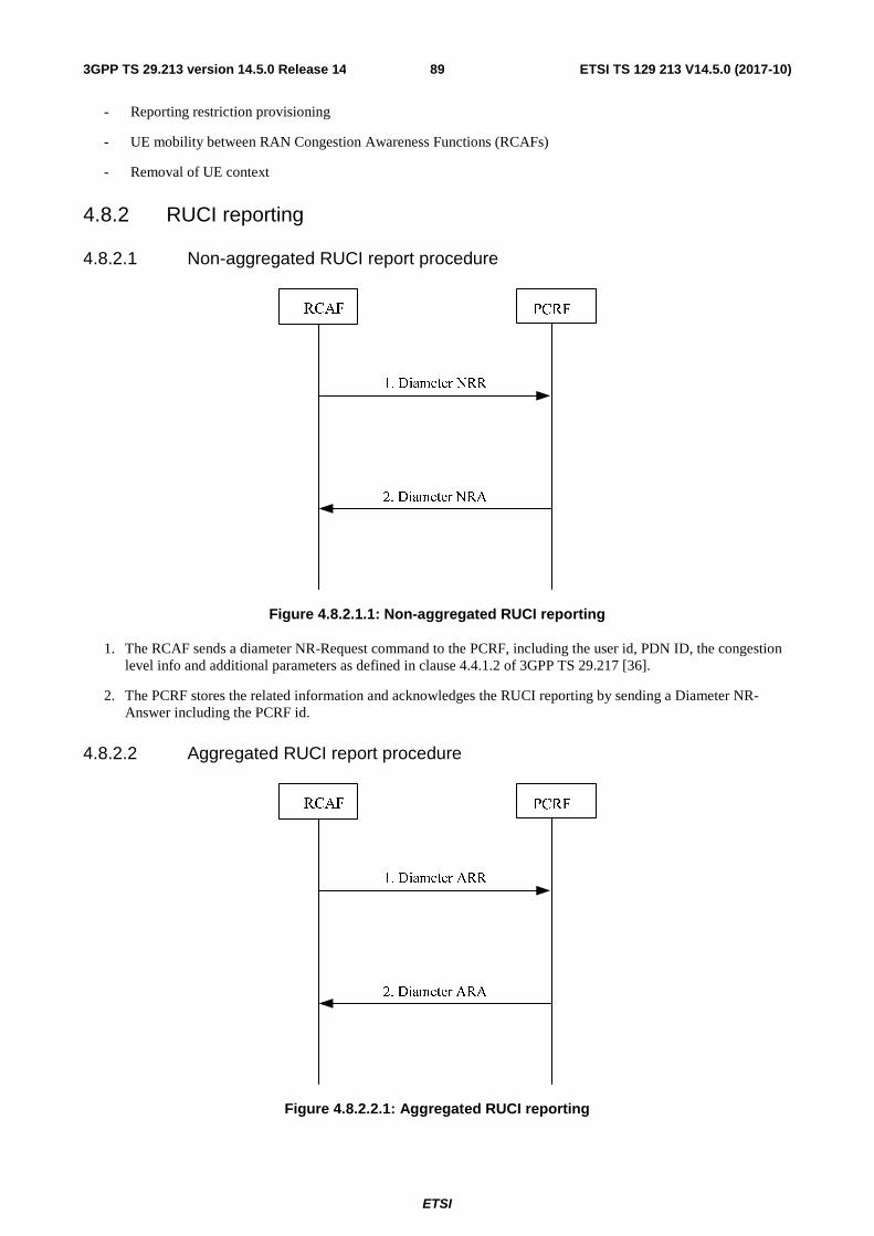
ETSI
ETSI TS 129 213 V14.5.0 (2017-10)893GPP TS 29.213 version 14.5.0 Release 14
- Reporting restriction provisioning
- UE mobility between RAN Congestion Awareness Functions (RCAFs)
- Removal of UE context
4.8.2 RUCI reporting
4.8.2.1 Non-aggregated RUCI report procedure
Figure 4.8.2.1.1: Non-aggregated RUCI reporting
1. The RCAF sends a diameter NR-Request command to the PCRF, including the user id, PDN ID, the congestion level info and additional parameters as defined in clause 4.4.1.2 of 3GPP TS 29.217 [36].
2. The PCRF stores the related information and acknowledges the RUCI reporting by sending a Diameter NR-Answer including the PCRF id.
4.8.2.2 Aggregated RUCI report procedure
Figure 4.8.2.2.1: Aggregated RUCI reporting
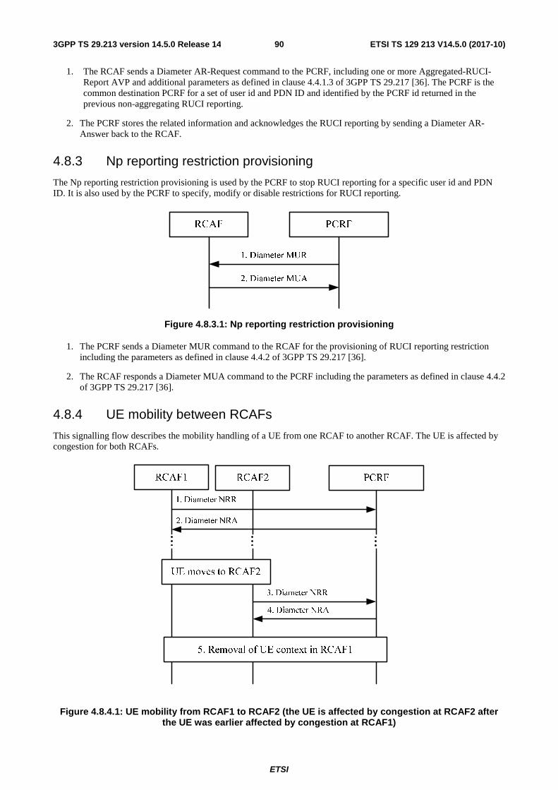
ETSI
ETSI TS 129 213 V14.5.0 (2017-10)903GPP TS 29.213 version 14.5.0 Release 14
1. The RCAF sends a Diameter AR-Request command to the PCRF, including one or more Aggregated-RUCI-Report AVP and additional parameters as defined in clause 4.4.1.3 of 3GPP TS 29.217 [36]. The PCRF is the common destination PCRF for a set of user id and PDN ID and identified by the PCRF id returned in the previous non-aggregating RUCI reporting.
2. The PCRF stores the related information and acknowledges the RUCI reporting by sending a Diameter AR-Answer back to the RCAF.
4.8.3 Np reporting restriction provisioning
The Np reporting restriction provisioning is used by the PCRF to stop RUCI reporting for a specific user id and PDN ID. It is also used by the PCRF to specify, modify or disable restrictions for RUCI reporting.
Figure 4.8.3.1: Np reporting restriction provisioning
1. The PCRF sends a Diameter MUR command to the RCAF for the provisioning of RUCI reporting restriction including the parameters as defined in clause 4.4.2 of 3GPP TS 29.217 [36].
2. The RCAF responds a Diameter MUA command to the PCRF including the parameters as defined in clause 4.4.2 of 3GPP TS 29.217 [36].
4.8.4 UE mobility between RCAFs
This signalling flow describes the mobility handling of a UE from one RCAF to another RCAF. The UE is affected by congestion for both RCAFs.
Figure 4.8.4.1: UE mobility from RCAF1 to RCAF2 (the UE is affected by congestion at RCAF2 after the UE was earlier affected by congestion at RCAF1)

ETSI
ETSI TS 129 213 V14.5.0 (2017-10)913GPP TS 29.213 version 14.5.0 Release 14
1. The UE is located in the RCAF1 which is affected by congestion. The RCAF1 sends a Diameter NRR command to the PCRF for reporting RUCI including the parameters as defined in clause 4.4.1.2 of 3GPP TS 29.217 [36].
2. The PCRF stores the identity of RCAF1 for the given UE and responds a Diameter NRA command to the RCAF1 including the parameters as defined in clause 4.4.1.2 of 3GPP TS 29.217 [36].
3. The UE moves to the RCAF2 which is also affected by congestion. The RCAF2 sends a Diameter NRR command to the PCRF for reporting RUCI of the same UE including the parameters as defined in clause 4.4.1.2 of 3GPP TS 29.217 [36].
4. The PCRF stores the identity of RCAF2 for the given UE and responds a Diameter NRA command to the RCAF2 including the parameters as defined in clause 4.4.1.2 of 3GPP TS 29.217 [36].
5. The PCRF initiates a removal of the UE context to RCAF1 to release the context of the given user id and PDN ID, including the parameters as defined in clause 4.4.4 of 3GPP TS 29.217 [36].
4.8.5 Removal of UE context
This signalling flow describes the removal of a UE context from the RCAF.
Figure 4.8.5.1: UE context removal in RCAF
1. The PCRF sends a Diameter MUR command to the RCAF to release the context of the given user id and PDN ID, including the parameters as defined in clause 4.4.4 of 3GPP TS 29.217 [36].
2. The RCAF responds with a Diameter MUA command to the PCRF including the parameters as defined in clause 4.4.4 of 3GPP TS 29.217 [36]. The RCAF releases the context corresponding to the given user id and PDN ID, including any reporting restriction.
4.9 Traffic Steering Control Procedures over St reference point
4.9.1 St Session Establishment
In the following procedure, the PCRF initiates the St session establishment procedure and provides the traffic steering control informaiton to the TSSF due to the PCRF determines that the traffic steering control is needed for the IP-CAN session.
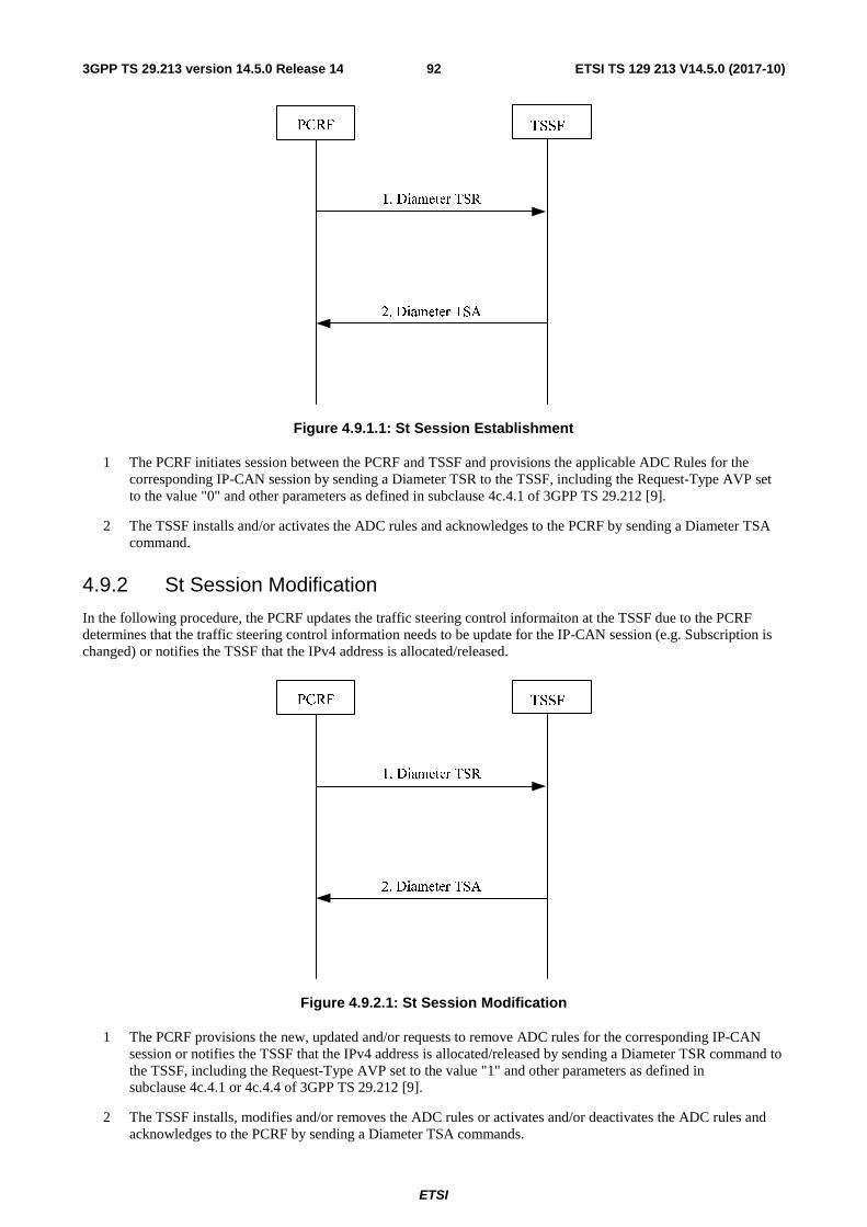
ETSI
ETSI TS 129 213 V14.5.0 (2017-10)923GPP TS 29.213 version 14.5.0 Release 14
TSSFPCRF
1. Diameter TSR
2. Diameter TSA
Figure 4.9.1.1: St Session Establishment
1 The PCRF initiates session between the PCRF and TSSF and provisions the applicable ADC Rules for the corresponding IP-CAN session by sending a Diameter TSR to the TSSF, including the Request-Type AVP set to the value "0" and other parameters as defined in subclause 4c.4.1 of 3GPP TS 29.212 [9].
2 The TSSF installs and/or activates the ADC rules and acknowledges to the PCRF by sending a Diameter TSA command.
4.9.2 St Session Modification
In the following procedure, the PCRF updates the traffic steering control informaiton at the TSSF due to the PCRF determines that the traffic steering control information needs to be update for the IP-CAN session (e.g. Subscription is changed) or notifies the TSSF that the IPv4 address is allocated/released.
TSSFPCRF
1. Diameter TSR
2. Diameter TSA
Figure 4.9.2.1: St Session Modification
1 The PCRF provisions the new, updated and/or requests to remove ADC rules for the corresponding IP-CAN session or notifies the TSSF that the IPv4 address is allocated/released by sending a Diameter TSR command to the TSSF, including the Request-Type AVP set to the value "1" and other parameters as defined in subclause 4c.4.1 or 4c.4.4 of 3GPP TS 29.212 [9].
2 The TSSF installs, modifies and/or removes the ADC rules or activates and/or deactivates the ADC rules and acknowledges to the PCRF by sending a Diameter TSA commands.

ETSI
ETSI TS 129 213 V14.5.0 (2017-10)933GPP TS 29.213 version 14.5.0 Release 14
4.9.3 St Session Termination
In the following procedure, the the PCRF initiates the St session termination procedure and removes all the traffic steering control informaiton to the TSSF due to the corresponding IP-CAN session is terminated or the H-PCRF determines that the traffic steering control information is not needed for the IP-CAN session any longer (e.g. Subscription has changed).
TSSFPCRF
1. Diameter STR
3. Diameter STA
2. Removes/deactivates
all the ADC rules
Figure 4.9.3.1: St Session Termination
1. The PCRF sends an STR to the TSSF to terminate the session between the PCRF and the TSSF.
2. The TSSF removes/deactivates all the ADC Rules which are applied to the session.
3. The TSSF sends an STA to acknowledge the STR.
4.9.4 St notification initiated by the TSSF
In the following procedure, the TSSF reports the ADC rule error when the ADC rule can’t be enforced any longer.
PCRFTSSF
1. Diameter TNR
2. Diameter TNA
Figure 4.9.x.1: St notification initiated by the TSSF

ETSI
ETSI TS 129 213 V14.5.0 (2017-10)943GPP TS 29.213 version 14.5.0 Release 14
1 The TSSF reports the ADC rules error by sending a Diameter TNR command to the PCRF as defined in subclause 4c.4.3 of 3GPP TS 29.212 [9].
2 The PCRF acknowledges to the TSSF by sending a Diameter TNA command.
4.10 Negotiation for future background data transfer procedure over Nt reference point
The following procedure shows the signaling flow for the SCEF to request the transfer policy for future background data transfer determined by the H-PCRF.
Figure 4.x.1: Negotiation for future background data transfer
1. Based on the SCS/AS request, the SCEF sends a Diameter BTR command to the H-PCRF for the request of transfer policy including the parameters as defined in subclause 4.4.1 of 3GPP TS 29.154 [56].
2. The H-PCRF determines one or more transfer policies based on the information received from the SCEF and other available information (e.g. network policy, existing transfer policies).
3. The H-PCRF sents a Diameter BTA command to the SCEF including the parameters as defined in subclause 4.4.1 of 3GPP TS 29.154 [56].
4. If there is more than one transfer policy provided from the H-PCRF to the SCEF in the BTA command, when the SCEF receives the selected transfer policy from the SCS/AS, the SCEF sends a Diameter BTR command to the H-PCRF with the selected transfer policy.
5. The H-PCRF acknowledges the BTR command by sending BTA command.
5 Binding Mechanism
5.1 Overview The binding mechanism associates the session information with the IP-CAN bearer that is intended to carry the service data flow.
For PCC rules with application identifier, and for certain IP-CAN types, up-link traffic can be received on other/additional IP-CAN bearers than the one determined by the binding mechanism (further details provided in clause 6.2.2.2 and the IP-CAN specific annexes of 3GPP TS 23.203 [2]).

ETSI
ETSI TS 129 213 V14.5.0 (2017-10)953GPP TS 29.213 version 14.5.0 Release 14
The binding mechanism includes three steps as defined in 3GPP TS 23.203 [2]:
1. Session binding.
2. PCC Rule authorization and QoS Rule generation.
3. Bearer binding.
The Session Binding function receives the Session Information and determines the relevant IP-CAN session. With this information the PCC Rule Authorization and QoS Rule generation function runs the policy rules and constructs the PCC rule(s) and if applicable, the QoS rule(s) if the authorization is granted. Finally the Bearer Binding function selects the IP-CAN bearer where the PCC rule(s) or QoS rule(s) should be installed within the IP-CAN session already known.
PCC Rule Authorization and QoS Rule generation function and Bearer Binding function can take place without Session Binding at certain IP-CAN Session events (e.g. IP-CAN Session Establishment).
5.2 Session Binding Session binding is the association of the AF session information to an IP-CAN session.
When the PCRF accepts an AA-Request from the AF over the Rx interface with service information, the PCRF shall perform session binding and associate the described service IP flows within the AF session information (and therefore the applicable PCC rules) to one and only one existing IP-CAN session. When the PCRF receives an AA-Request from the P-CSCF acting as an AF over the Rx interface for P-CSCF Restoration, the PCRF shall perform session binding and associate the request to the existing IMS PDN connection and perform P-CSCF Restoration for that impacted IMS PDN connection. This association is done comparing the user IP address received via the Rx interface in either the Frame-IP-Address AVP or the Framed-Ipv6-Prefix AVP with the Ipv4 address or Ipv6 prefix received via the Gx interface. The UE Identity if present in the Subscription-Id AVP and the PDN information if available in the Called-Station-Id AVP may also assist on this association. The Domain identity if available in the IP-Domain-Id AVP may also assist on this association, e.g. if other user identity information than the UE IP address is unavailable and the UE IP addresses is not unique for a certain APN.
NOTE 1: The UE IP address is unique per Domain identity.
NOTE 2: The IP-Domain-Id AVP is helpful in the following scenario: Within a PLMN, there are several separate IP address domains, with PCEF(s) that allocate Ipv4 IP addresses out of the same private address range to Ues. The same IP address can thus be allocated to Ues served by PCEFs in different address domains. If one PCRF controls several PCEFs in different IP address domains, the UE IP address is thus not sufficient for the session binding. An AF can serve Ues in different IP address domains, either by having direct IP interfaces to those domains, or by having interconnections via NATs in the user plane between PCEFs and the AF. If a NAT is used, the AF obtains the IP address allocated to the UE via application level signalling and supplies it for the session binding as Framed-IP-Address to the PCRF. The AF supplies an IP-Domain-Id value denoting the IP address domain behind the NAT in addition. The AF can derive the appropriate value from the source address (allocated by the NAT) of incoming user plane packets.
NOTE 3:When the scenario described in NOTE 2 applies and the AF is a P-CSCF it is assumed that the P-CSCF has direct IP interfaces to the different IP address domains and that no NAT is located between P-GW and P-CSCF. How a non-IMS AF obtains the UE private IP address to be provided to the PCRF is out of scope of the present release; it is unspecified how to support applications that use a protocol that does not retain the original UE’s private IP address.
If the Domain identity is not used to assist association, the PCRF will determine that the UE has an IP-CAN session if the IP address (Ipv4 or Ipv6) received over the Rx interface matches the Ipv4 address or Ipv6 prefix received via one or more of the following interfaces: Gx interface and S9 interface, and if the UE identity is used to assist the association, the UE identity received over the Rx interface matches the UE identity received via one or more of the following interfaces: Gx interface and S9 interface.
If the Domain identity is used to assist association, the PCRF will determine that the UE has an IP-CAN session if the Domain identity received over the Rx interface matches the PCEF Identity received via the Gx interface, and the IP address (Ipv4) received over the Rx interface matches the Ipv4 address received via the Gx interface.

ETSI
ETSI TS 129 213 V14.5.0 (2017-10)963GPP TS 29.213 version 14.5.0 Release 14
For the roaming scenario, the Domain identity may be used for session binding when the AF and PCEF are located in same PLMN, i.e. for the home routed case, the Domain identity may be used by the (H-)PCRF for session binding, and for the visited case, Domain identity could be used by the V-PCRF for session binding.
For an IP-CAN session associated to a dedicated APN for the purpose of offering services to remote UEs via a ProSe UE-to-network relay UE, the PCRF shall use the UE IPv6 prefix alone in the session binding.
NOTE 4: In case the UE identity in the IP-CAN and the application level identity for the user are of different kinds, the PCRF needs to maintain, or have access to, the mapping between the identities. Such mapping is not subject to specification within this TS.
NOTE 5: An Ipv6 address provided over Rx matches an Ipv6 prefix provided over Gx or S9 if the Ipv6 address belongs to the Ipv6 (sub-)network prefix.
NOTE 6: The PCRF derives the PCEF identity from the Origin-Host AVP of the CCR command received from the PCEF. In order to correlate the PCEF Identity and the domain identity received over the Rx interface, the PCRF uses configured mapping between those identities. The Domain Identity is useful for assistance in session binding if the Origin-Host of the Gx CCR command is not modified by intermediate Diameter proxies deployed between the PCEF and the PCRF.
NOTE 7: The PCEF identity is not transported over S9 reference point in the present release. So for the visited access with AF located in HPLMN case, session binding assisted with Domain identity is not supported in the present release. Session binding is still possible based on other available information in addition to the IP address when provided by the AF, according to the current procedures.
If the PCRF uses the Called-Station-Id AVP to assist the association, the PCRF shall apply the procedures in Annex I to match APN information.
As a result from the session binding function, the PCRF identifies what IP-CAN session the current AF session is related with. If the PCRF is not capable of executing the Session Binding, the PCRF shall issue an AA-Answer command to the AF with a negative response.
5.3 PCC Rule Authorization and QoS Rule Generation The PCRF shall perform the PCC rule authorization and QoS rule generation when the PCRF receives session information from an AF over Rx interface, when the PCRF receives notification of IP-CAN session events (e.g. establishment, modification) from the PCEF over Gx or S9 interface, when the PCRF receives IP-CAN events from the BBERF over Gxa/Gxc interface, or the PCRF receives a notification from the SPR that calls for a policy decision. The PCRF shall also perform PCC Rule Authorization and QoS Rule generation for dynamic PCC Rules already provisioned to the PCEF and dynamic QoS rules already provisioned to the BBERF due to internal PCRF triggers (e.g. policies are included or modified within PCRF).
If the PCRF receives any traffic mapping information from the BBF that does not match any service data flow filter, the PCRF shall also perform PCC and/or QoS rule authorization when the UE’s subscriber profile allows subscription based authorization. In this case, the PCRF shall treat the received traffic mapping information as if it is service data flow filter information.
If the PCRF receives from the AF a reference ID together with the AF session information, the PCRF may provide it to the SPR in order to retrieve the corresponding transfer policy. The PCRF shall derive the PCC rules for the background data transfer according to the retrieved transfer policy.
NOTE 1: A transfer policy is only valid within its time window. The removal of outdated transfer policies from the SPR is up to implementation.
If the PCRF receives information from the SPR for the invocation/revocation of a Priority EPS Bearer service (i.e. the MPS EPS Priority is set/removed or the MPS Priority Level changes while the MPS EPS Priority is set) , then the PCRF should change the QCI/ARP of the dynamic PCC/QoS rules that have the same QCI/ARP as for the present default EPS bearer with the new QCI/ARP assigned to the default EPS bearer unless those PCC rules contain an indication that they have to be bound to the default EPS bearer. If there are active non-MPS services, the QCI/ARP of the PCC/QoS rules related to the non-MPS services shall also be changed.
If the PCRF receives information from the SPR that invokes/revokes the IMS Signalling Priority or changes the MPS Priority Level while IMS Signaling Priority is enabled, then the PCRF should

ETSI
ETSI TS 129 213 V14.5.0 (2017-10)973GPP TS 29.213 version 14.5.0 Release 14
- change the ARP of the dynamic PCC/QoS rules applicable to the IM CN signalling
- replace the predefined PCC rules applicable to the IM CN signalling by predefined rules that apply when the IMS Signalling Priority is set according to operator policies
When IMS Signalling Priority is set, the PCRF should keep the ARP assigned to the default EPS bearer higher than the ARP related to the IM CN signalling bearer.
NOTE 2. IMS Signalling Priority only applies to an APN enabled for IMS.
The PCRF assigns appropriate QoS parameters (QCI, ARP, GBR, MBR, etc.) to each PCC or QoS rule. The PCRF takes the information received over Rx into account for determining the appropriate QCI/ARP. If the Rx authorization indicates IMS Multimedia Priority Service, then the PCRF shall allow the prioritization of the MPS session according to clauses 4.5.19.1.3 and 4a.5.14.1.3 in 3GPP TS 29.212 [9] for Gx/Gxx respectively. If the Rx authorization indicates Group Communication Service prioritization as described in 3GPP TS 23.468 [34], then the PCRF shall allow the prioritization of the Group Communication session according to clause 4.5.19 in 3GPP TS 29.212 [9].
The PCRF authorizes the affected PCC rules and /or QoS rules after successful Session Binding. By the authorization process the PCRF will determine whether the user can have access to the requested services and under what constraints. If so, the PCC rules and QoS rules are created or modified. If the Session Information is not authorized, a negative answer shall be issued to the AF by sending an AA-Answer command.
The PCRF assigns an appropriate QCI to each PCC or QoS rule. IP-CAN specific restrictions and other information available to the PCRF (e.g. users subscription information, operator policies) shall be taken into account. Each PCC or QoS rule shall receive a QCI that can be supported by the IP-CAN. The PCRF shall ensure consistency between the QoS rules and PCC rules authorized for the same service data flow when QoS rules are derived from corresponding PCC rules.
If PrioritySharing feature is supported over Rx reference point as described in 3GPP TS 29.214 [10], the PCRF shall apply the priority sharing procedures as described in 3GPP TS 29.212 [9], subclauses 4.5.27 and 4a.5.17, if applicable.
In roaming scenarios, the V-PCRF may further authorize the rules received from the H-PCRF based on local operator policy. Depending on the local policy, the V-PCRF may change the authorized QoS for the affected rules. If local authorization of the rules fails, the V-PCRF shall issue a negative answer to the H-PCRF.
5.4 Bearer Binding The Bearer Binding function is responsible for associating a PCC rule and QoS rule (if applicable) to an IP-CAN bearer within the IP-CAN session. The QoS demand in the rule, as well as the service data flow template, is input to the bearer binding. The selected bearer shall have the same QCI and ARP as the one indicated by the PCC or QoS rule.
When Rule-Bound-to-Default-Bearer feature is supported as described in 3GPP TS 29.212 [9], the value included within the Default-Bearer-Indication AVP shall be used as input for the bearer binding instead of the QoS demand in the rule.
NOTE 1: The PCRF provides the appropriate ARP/QCI for both PCC Rules and default bearer QoS so that the PCEF can perform a valid bearer binding. Alternatively, when Rule-Bound-to-Default-Bearer feature is supported, the PCRF can provide the Default-Bearer-Indication AVP within the PCC Rules to indicate that these PCC Rules have to be bound to the default bearer regardless of the provisioned ARP/QCI.
The Bearer Binding Function (BBF) is located either at the BBERF or at the PCEF.
The PCRF shall supply the PCC rules to be installed, modified or removed over Gx interface to PCEF. If there are gateway controls sessions associated with the Gx session, the PCRF shall also supply the QoS rules to be installed, modified, or removed over Gxa/Gxc interface to the BBERF.
When Rule-Bound-to-Default-Bearer feature is supported, the BBF located at the PCEF shall bind to the default bearer the PCC rules that have indicated so.
For the rules that do not contain an indication that they have to be bound to the default bearer, the BBF shall then check the QoS class identifier and ARP indicated by the rule and bind the rule with an IP-CAN bearer that has the same QoS class identifier and ARP. The BBF shall evaluate whether it is possible to use one of the existing IP-CAN bearers or not and, if applicable, whether to initiate IP-CAN bearer modification or not. If none of the existing bearers are possible to

ETSI
ETSI TS 129 213 V14.5.0 (2017-10)983GPP TS 29.213 version 14.5.0 Release 14
use, the BBF should initiate the establishment of a suitable IP-CAN bearer. The BBF should not bind rules with the PS to CS session continuity indicator to the same bearer as the rules without the PS to CS session continuity indicator.
NOTE 2: For an IP-CAN, limited to a single IP-CAN bearer per IP-CAN session, the bearer is implicit, so finding the IP-CAN session is sufficient for successful bearer binding.
NOTE 3: The handling of a rule with MBR>GBR is up to operator policy (e.g. an independent IP-CAN bearer may be maintained for that SDF to prevent unfairness between competing SDFs).
NOTE 4: The QCI and ARP (including the Priority-Level, Pre-emption-Capability and Pre-emption-Vulnerability) are used for the bearer binding. Depending on operator policy, only the QCI and ARP Priority-Level can be used for bearer binding. In such a case, it is left to operator policy to determine whether different PCC rules with the same QCI and ARP Priority-Level but different Pre-emption-Capability and Pre-emption-Vulnerability can be bound to the same bearer.
For an IP-CAN, where the BBF gains no information on what IP-CAN bearer the UE selects to send an uplink IP flow on, the binding mechanism shall assume that, for bi-directional service data flows, both downlink and uplink packets travel on the same IP-CAN bearer.
Whenever the service data flow template, the QoS authorization of a PCC/QoS rule or the negotiated traffic mapping information change, the existing bearer bindings shall be re-evaluated. The re-evaluation may, for a service data flow, require a new binding with another IP-CAN bearer. The BBF should, if the PCRF requests the same change to the ARP/QCI for all PCC/QoS Rules bound to the same bearer, modify the bearer ARP/QCI as requested.
NOTE 5: A QoS change of the default EPS bearer causes the bearer binding for PCC/QoS rules previously bound to the default EPS bearer to be re-evaluated.
During PCC/QoS rules enforcement, if packet filters are provided to the UE, the BBF shall provide packet filters with the same content as that in the SDF template filters received over the Gx/Gxx interface from the PCRF within the Flow-Description or the Flow-Information AVP. The representation/format of the packet filters provided by the network to the UE is access-system dependent and may vary between accesses and also may be different from that of the SDF template filter on the Gx/Gxx interface. The PCRF may control the provisioning of packet filters to the UE, i.e. which filters are required to be sent to the UE, as described in 3GPP TS 29.212 [9].
If PCC rule(s) with application identifier(s) are the only PCC rule(s) that are bound to a bearer which requires traffic mapping information, the PCEF shall derive traffic mapping information based on implementation specific logic (e.g. traffic mapping information that effectively disallows any useful packet flows in uplink direction as described in clause 15.3.3.4 of 3GPP TS 23.060 [3]) and provides it to the UE.
NOTE 6: For GPRS and EPS, the state of TFT packet filters, as defined in 3GPP TS 23.060 [3], for an IP-CAN session requires that there is at most one bearer with no TFT packet filter for the uplink direction.
Requirements specific for each type of IP-CAN are defined in the IP-CAN specific Annex. The Bearer Binding Function may also be located in the PCRF (e.g. as specified in Annex D for GPRS running UE only IP-CAN bearer establishment mode). Selection of the Bearer Binding location shall be based on the Bearer Control Mode selected by the PCRF.
6 QoS Parameters Mapping
6.1 Overview Several QoS parameters mapping functions are needed during PCC interaction. These functions are located at the AF, PCRF, PCEF and UE. The main purpose of these mapping functions is the conversion of QoS parameters from one format to another. Examples of QoS information are:
- Parts of a session description language (SDI), e.g. SDP, MPD.
- IP QoS parameters.
- Access specific QoS parameters.

ETSI
ETSI TS 129 213 V14.5.0 (2017-10)993GPP TS 29.213 version 14.5.0 Release 14
One QoS mapping function is located at the AF, which maps the application specific information into the appropriate AVPs that are carried over the Rx interface. The AF derives information about the service from the SDI or from other sources. The mapping is application specific. If SDP (IETF RFC 2327 [11]) is used as SDI, the AF should apply the mapping described in clause 6.2. If MPD (3GPP TS 26.247 [30]) is used, the AF may apply the mapping described in Annex X in 3GPP TS 26.247 [30]. For IMS, the mapping rules in clause 6.2 shall be used at the P-CSCF. The AF passes service information to the PCRF over the Rx interface. Subclause 6.2 specifies the QoS parameter mapping functions at the AF applicable for all IMS P-CSCFs regardless of the access technology.
One QoS mapping function is located at the PCRF, which maps the service information received over the Rx interface into IP QoS parameters (e.g. QCI, GBR, MBR, ARP, …). This mapping is access independent. Subclause 6.3 specifies the QoS mapping functions at the PCRF applicable for all accesses.
The other mapping functions located at PCEF, BBERF, and UE are implementation dependent and are not specified within this specification except for GPRS case.
The PCRF notes and authorizes the IP flows described within this service information by mapping from service information to Authorized IP QoS parameters for transfer to the PCEF/BBERF via the Gx/Gxx interface. Both the PCEF and BBERF will map from the Authorized IP QoS parameters to the access specific QoS parameters. For GPRS, the GGSN acting as PCEF will map from the Authorized IP QoS parameters to the Authorized UMTS QoS parameters.
The general QoS mapping framework is shown in figure 6.1.1.
GW
PCEF/BBERF PCRF (2)
IP BS Manager
Translation / Mapping
function (4)
Access- Specific BS Manager (5)
UE (3)
Translation / Mapping function
Access-Specific BS
Manager
IP BS Manager
Application
Gx/Gxx
AF session signalling , possibly with SDI
Service information
Rx
AF (1) SDI
Mapping function
Signalling path
LEGEND
Policy Engine Authz IP QoS
parameters
Access-specific QoS parameters
Figure 6.1.1: Framework for QoS mapping
NOTE 1: The AF can derive the Service information from the AF session signalling.
NOTE 2: Service Information on Rx interface to Authorized IP QoS parameters mapping.
NOTE 3: For the UE initiated bearer setup, the UE may derive IP QoS parameters, requested Access-Specific QoS parameters mapping and Authorized Access-Specific QoS parameters from the AF session signalling.
NOTE 4: Authorized IP QoS parameters to Authorized Access-Specific QoS parameters mapping.

ETSI
ETSI TS 129 213 V14.5.0 (2017-10)1003GPP TS 29.213 version 14.5.0 Release 14
NOTE 5: Access Specific QoS parameters with Authorized Access-Specific QoS parameters comparison.
6.1.1 UE-Initiated IP-CAN bearers
This clause covers the case where the UE is capable to initiate/modify the IP-CAN bearers sending requests to the PCEF/BBERF. When a UE desires to establish/modify an IP-CAN bearer the following steps are followed:
1. The AF can map from SDI within the AF session signalling to service information passed to the PCRF over the Rx interface. (see clause 6.2 if SDP is used as SDI).
2. The PCRF shall map from the service information received over the Rx interface to the Authorized IP QoS parameters that shall be passed to the PCEF/BBERF via the Gx/Gxx interface. The mapping is performed for each IP flow. Upon a request from the PCEF/BBERF, the PCRF combines per direction the individual Authorized IP QoS parameters per flow (see clause 6.3).
3. The UE derives access specific QoS parameters, e.g. UMTS QoS parameters, and, if an IP BS manager is present, IP QoS parameters from the AF session signalling in an application specific manner. The IP and access specific QoS parameters should be generated according to application demands. For GPRS, the recommendations for conversational (3GPP TS 26.114 [29]) or streaming applications (3GPP TS 26.234 [6]) should also be taken into account when the UE derives the IP and UMTS QoS parameters. If SDP is used as SDI, e.g. for IMS, the UE should apply clause 6.5.1.and should also apply mapping rules for the authorised QoS parameters in clause 6.5.2 to derive the maximum values for the different requested bit rates and traffic classes. In case the UE multiplexes several IP flows onto the same PDP Context, it has to combine their IP and UMTS QoS parameters. If an IP BS manager is present, the Translation/Mapping function maps the IP QoS parameters to the corresponding UMTS QoS parameters.
4. The PCEF/BBERF shall map from the Authorized IP QoS parameters received from PCRF to the Authorized access specific QoS parameters.
For GPRS. The GGSN shall map to the Authorized UMTS QoS parameters (see clause 6.4.1.1).
5. The PCEF/BBERF shall compare the requested access specific QoS parameters against the authorized access specific QoS parameters.
For GPRS, the GGSN shall compare the UMTS QoS parameters of the PDP context against the Authorized UMTS QoS parameters (see clause 6.4.1.2).
The mapping that takes place in the UE and the network should be compatible in order to ensure that the PCEF will be able to correctly authorize the session.
Figure 6.1.1.1 shows the different kind of QoS parameters in the different points of QoS mapping figure. Due to the UE requests, there are bidirectional flows between the UE and the PCRF.
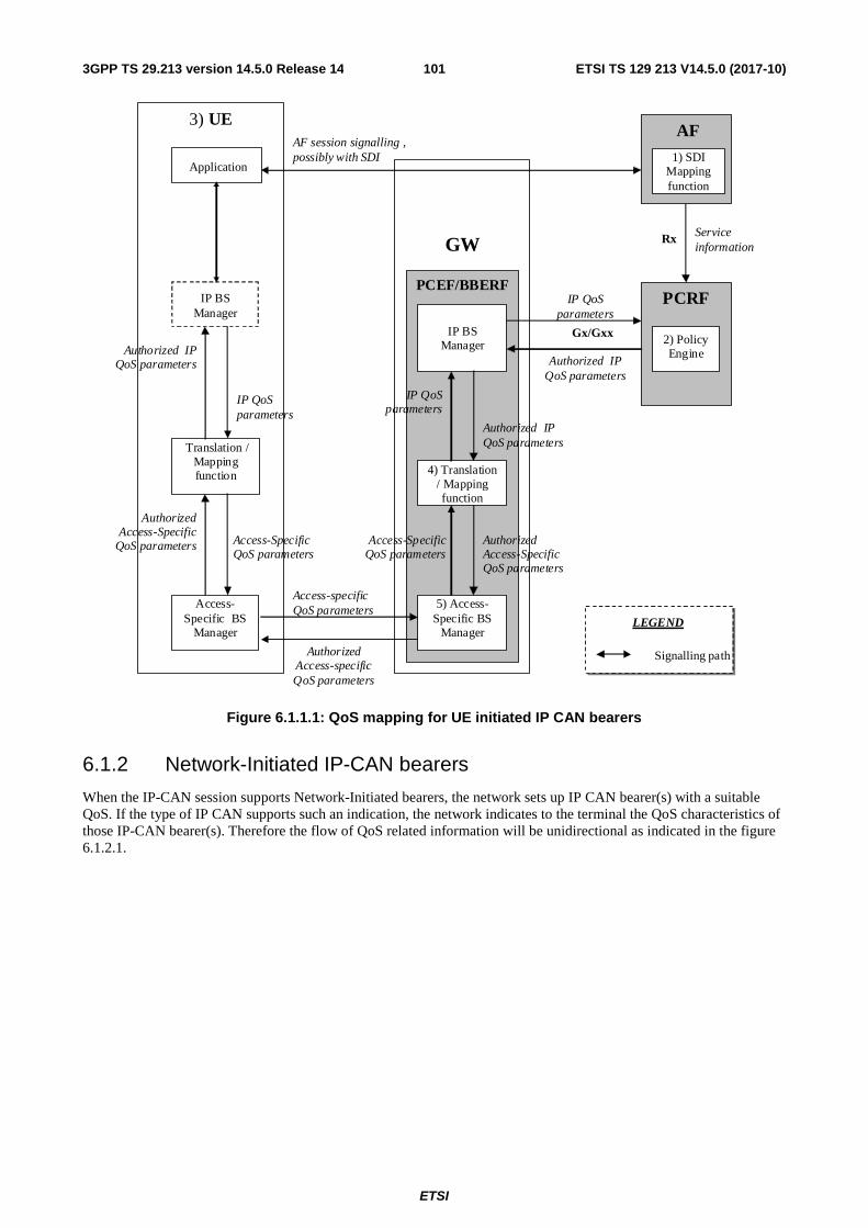
ETSI
ETSI TS 129 213 V14.5.0 (2017-10)1013GPP TS 29.213 version 14.5.0 Release 14
GW
PCEF/BBERF PCRF
IP BS
Manager
4) Translation / Mapping function
5) Access- Specific BS
Manager
3) UE
Translation / Mapping function
Access-Specific BS
Manager
IP BS Manager
Application
Gx/Gxx
AF session signalling , possibly with SDI
Service information
Rx
AF 1) SDI
Mapping function
Signalling path
LEGEND
2) Policy Engine
Authorized IP QoS parameters
Access-specific QoS parameters
IP QoS parameters
Authorized IP QoS parameters
IP QoS parameters
Authorized Access-Specific QoS parameters
Access-Specific QoS parameters
Authorized Access-specific QoS parameters
Access-Specific QoS parameters
IP QoS parameters
Authorized IP QoS parameters
Authorized Access-Specific
QoS parameters
Figure 6.1.1.1: QoS mapping for UE initiated IP CAN bearers
6.1.2 Network-Initiated IP-CAN bearers
When the IP-CAN session supports Network-Initiated bearers, the network sets up IP CAN bearer(s) with a suitable QoS. If the type of IP CAN supports such an indication, the network indicates to the terminal the QoS characteristics of those IP-CAN bearer(s). Therefore the flow of QoS related information will be unidirectional as indicated in the figure 6.1.2.1.
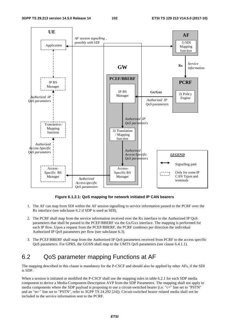
ETSI
ETSI TS 129 213 V14.5.0 (2017-10)1023GPP TS 29.213 version 14.5.0 Release 14
GW
PCEF/BBERF PCRF
IP BS
Manager
3) Translation / Mapping function
Access- Specific BS
Manager
UE
Translation / Mapping function
Access-Specific BS
Manager
IP BS Manager
Application
Gx/Gxx
AF session signalling , possibly with SDI
Service information
Rx
AF 1) SDI
Mapping function
2) Policy Engine
Authorized IP QoS parameters
Authorized IP QoS parameters
Authorized Access-Specific QoS parameters
Authorized Access-specific QoS parameters
Authorized IP QoS parameters
Authorized Access-Specific
QoS parameters
Signalling path
Only for some IP CAN Types and terminals
LEGEND
Figure 6.1.2.1: QoS mapping for network initiated IP CAN bearers
1. The AF can map from SDI within the AF session signalling to service information passed to the PCRF over the Rx interface (see subclause 6.2 if SDP is used as SDI).
2. The PCRF shall map from the service information received over the Rx interface to the Authorized IP QoS parameters that shall be passed to the PCEF/BBERF via the Gx/Gxx interface. The mapping is performed for each IP flow. Upon a request from the PCEF/BBERF, the PCRF combines per direction the individual Authorized IP QoS parameters per flow (see subclause 6.3).
3. The PCEF/BBERF shall map from the Authorized IP QoS parameters received from PCRF to the access specific QoS parameters. For GPRS, the GGSN shall map to the UMTS QoS parameters (see clause 6.4.1.1).
6.2 QoS parameter mapping Functions at AF The mapping described in this clause is mandatory for the P-CSCF and should also be applied by other AFs, if the SDI is SDP.
When a session is initiated or modified the P-CSCF shall use the mapping rules in table 6.2.1 for each SDP media component to derive a Media-Component-Description AVP from the SDP Parameters. The mapping shall not apply to media components where the SDP payload is proposing to use a circuit-switched bearer (i.e. "c=" line set to "PSTN" and an "m=" line set to "PSTN", refer to 3GPP TS 24.292 [24]). Circuit-switched bearer related media shall not be included in the service information sent to the PCRF.

ETSI
ETSI TS 129 213 V14.5.0 (2017-10)1033GPP TS 29.213 version 14.5.0 Release 14
Table 6.2.1: Rules for derivation of service information within Media-Component-Description AVP from SDP media component

ETSI
ETSI TS 129 213 V14.5.0 (2017-10)1043GPP TS 29.213 version 14.5.0 Release 14
service information per Media-Component-
Description AVP (see notes 1 and 7)
Derivation from SDP Parameters (see Note 2)
Media-Component-Number ordinal number of the position of the "m=" line in the SDP
AF-Application-Identifier The AF-Application-Identifier AVP may be supplied or omitted, depending on the application. For IMS, if the AF-Application-Identifier AVP is supplied, its value should not demand application specific bandwidth or QoS class handling unless the IMS application is capable of handling a QoS downgrading.
Media-Type The Media Type AVP shall be included with the same value as supplied for the media type in the "m=" line.
Flow-Status IF port in m-line = 0 THEN Flow-Status:= REMOVED; ELSE IF Transport in m-line is "TCP" or "TCP/MSRP" THEN (NOTE 9) Flow-Status := ENABLED; ELSE /* UDP or RTP/AVP transport IF a=rtcp-mux is negotiated THEN Flow-Status :=ENABLED; (NOTE 12 and 13) ELSE IF a=recvonly THEN IF <SDP direction> = UE originated (NOTE 8) THEN Flow-Status := ENABLED_DOWNLINK; (NOTE 4) ELSE /* UE terminated (NOTE 8) */ Flow-Status := ENABLED_UPLINK; (NOTE 4) ENDIF; ELSE IF a=sendonly THEN IF <SDP direction> = UE originated (NOTE 8) THEN Flow-Status := ENABLED_UPLINK; (NOTE 4) ELSE /* UE terminated (NOTE 8) */ Flow-Status := ENABLED_DOWNLINK; (NOTE 4) ENDIF; ELSE IF a=inactive THEN Flow-Status :=DISABLED; ELSE /* a=sendrecv or no direction attribute */ Flow-Status := ENABLED (NOTE 4) ENDIF; ENDIF; ENDIF; ENDIF; ENDIF; ENDIF; (NOTE 5)

ETSI
ETSI TS 129 213 V14.5.0 (2017-10)1053GPP TS 29.213 version 14.5.0 Release 14
service information per Media-Component-
Description AVP (see notes 1 and 7)
Derivation from SDP Parameters (see Note 2)
Max-Requested-Bandwidth-UL
IF <SDP direction> = UE terminated (NOTE 8) THEN IF Transport in m-line is "TCP" or "TCP/MSRP" THEN (NOTE 9) IF a=recvonly or a=sendrecv or no direction attribute THEN IF b=AS:<bandwidth> is present and ( b=TIAS:<Tibandwidth> is not present or is present but not supported ) THEN Max-Requested-Bandwidth-UL:= <bandwidth> * 1000; /* Unit bit/s ELSE IF b=TIAS:<Tibandwidth> is present and supported THEN Max-Requested-Bandwidth-UL:= <Transport-dependent bandwidth> (NOTE 11) /* Unit bit/s ELSE Max-Requested-Bandwidth-UL:= <Operator specific setting>; ENDIF; ENDIF; ELSE Max-Requested-Bandwidth-UL:= <Operator specific setting>, (NOTE 10) ENDIF; ELSE /* UDP or RTP/AVP transport IF b=AS:<bandwidth> is present and ( b=TIAS:<Tibandwidth> is not present or is present but not supported ) THEN IF a=rtcp-mux is negotiated(NOTE 13) THEN IF b=RR:<rrbandwidth> is present OR b=RS:<rsbandwidth> is present THEN Max-Requested-Bandwidth-UL:= <bandwidth> * 1000 + <rrbandwidth> + <rsbandwidth>; (NOTE 3; NOTE 6) ELSE Max-Requested-Bandwidth-UL:= <bandwidth> * 1050; /* Unit is bit/s ENDIF ELSE Max-Requested-Bandwidth-UL:= <bandwidth> * 1000; /* Unit is bit/s ENDIF; ELSE IF b=TIAS:<Tibandwidth> is present and supported THEN IF a=rtcp-mux is negotiated (NOTE 13) THEN IF b=RR:<rrbandwidth> is present OR b=RS:<rsbandwidth> is present THEN Max-Requested-Bandwidth-UL:= <Transport-dependent bandwidth> (NOTE 11) + <rrbandwidth> + <rsbandwidth>; (NOTE 3; NOTE 6) ELSE Max-Requested-Bandwidth-UL:= <Transport-dependent bandwidth> * 1.05 (NOTE 11) /* Unit bit/s ENDIF ELSE Max-Requested-Bandwidth-UL:= <Transport-dependent bandwidth> (NOTE 11) /* Unit bit/s ENDIF; ELSE Max-Requested-Bandwidth-UL:= <Operator specific setting>, or AVP not supplied; ENDIF; ENDIF; ENDIF ELSE Consider SDP in opposite direction ENDIF
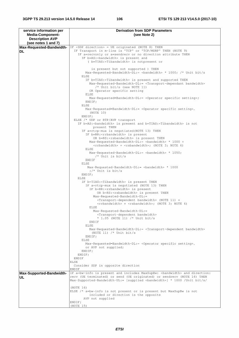
ETSI
ETSI TS 129 213 V14.5.0 (2017-10)1063GPP TS 29.213 version 14.5.0 Release 14
service information per Media-Component-
Description AVP (see notes 1 and 7)
Derivation from SDP Parameters (see Note 2)
Max-Requested-Bandwidth-DL
IF <SDP direction> = UE originated (NOTE 8) THEN IF Transport in m-line is "TCP" or "TCP/MSRP" THEN (NOTE 9) IF a=recvonly or a=sendrecv or no direction attribute THEN IF b=AS:<bandwidth> is present and ( b=TIAS:<Tibandwidth> is notpresent or is present but not supported ) THEN Max-Requested-Bandwidth-DL:= <bandwidth> * 1000; /* Unit bit/s ELSE IF b=TIAS:<Tibandwidth> is present and supported THEN Max-Requested-Bandwidth-DL:= <Transport-dependant bandwidth> /* Unit bit/s (see NOTE 11) OR Operator specific setting ELSE Max-Requested-Bandwidth-DL:= <Operator specific setting>; ENDIF; ELSE Max-Requested-Bandwidth-DL:= <Operator specific setting>, (NOTE 10) ENDIF; ELSE /* UDP or RTP/AVP transport IF b=AS:<bandwidth> is present and b=TIAS:<Tibandwidth> is not present THEN IF a=rtcp-mux is negotiated(NOTE 13) THEN IF b=RR:<rrbandwidth> is present OR b=RS:<rsbandwidth> is present THEN Max-Requested-Bandwidth-DL:= <bandwidth> * 1000 + <rrbandwidth> + <rsbandwidth>; (NOTE 3; NOTE 6) ELSE Max-Requested-Bandwidth-DL:= <bandwidth> * 1050; /* Unit is bit/s ENDIF ELSE Max-Requested-Bandwidth-DL:= <bandwidth> * 1000 ;/* Unit is bit/s ENDIF; ELSE IF b=TIAS:<Tibandwidth> is present THEN IF a=rtcp-mux is negotiated (NOTE 13) THEN IF b=RR:<rrbandwidth> is present OR b=RS:<rsbandwidth> is present THEN Max-Requested-Bandwidth-DL:= <Transport-dependent bandwidth> (NOTE 11) + <rrbandwidth> + <rsbandwidth>; (NOTE 3; NOTE 6) ELSE Max-Requested-Bandwidth-DL:= <Transport-dependent bandwidth> * 1.05 (NOTE 11) /* Unit bit/s ENDIF ELSE Max-Requested-Bandwidth-DL:= <Transport-dependent bandwidth> (NOTE 11) /* Unit bit/s ENDIF; ELSE Max-Requested-Bandwidth-DL:= <Operator specific setting>, or AVP not supplied; ENDIF; ENDIF; ENDIF ELSE Consider SDP in opposite direction ENDIF
Max-Supported-Bandwidth-UL
IF a=bw-info is present and includes MaxSupBw: <bandwidth> and direction: recv (UE terminated) or send (UE originated) or sendrecv (NOTE 14) THEN Max-Supported-Bandwidth-UL:= [supplied <bandwidth>] * 1000 /Unit bit/s/ (NOTE 16) ELSE /* a=bw-info is not present or is present but MaxSupBw is not included or direction is the opposite AVP not supplied ENDIF; (NOTE 15)

ETSI
ETSI TS 129 213 V14.5.0 (2017-10)1073GPP TS 29.213 version 14.5.0 Release 14
service information per Media-Component-
Description AVP (see notes 1 and 7)
Derivation from SDP Parameters (see Note 2)
Max-Supported-Bandwidth-DL
IF a=bw-info is present and includes MaxSupBw : <bandwidth> and direction: send (UE terminated) or recv (UE originated) or sendrecv (NOTE 14)THEN Max-Supported-Bandwidth-DL:= [supplied <bandwidth>] * 1000 /Unit bit/s/ (NOTE 16) ELSE /* a=bw-info is not present or is present but MaxSupBw is not included or direction is the opposite AVP not supplied ENDIF; (NOTE 15)
Min-Desired-Bandwidth-UL
IF a=bw-info is present and includes MinDesBw : <bandwidth> and direction: recv (UE terminated) or send (UE originated) or sendrecv (NOTE 14) THEN Min-Desired-Bandwidth-UL:= supplied <bandwidth> * 1000 /Unit bit/s/ (NOTE 16) ELSE /* a=bw-info is not present or is present but MinDesBw is not included or direction is the opposite AVP not supplied ENDIF;
Min-Desired-Bandwidth-DL
IF a=bw-info is present and includes MinDesBw : <bandwidth> and direction: send (UE terminated) or recv (UE originated) or sendrecv (NOTE 14) THEN Min-Desired-Bandwidth-DL:= [supplied <bandwidth>] * 1000 /Unit bit/s/ (NOTE 16) ELSE /* a=bw-info is not present or is present but MinDesBw is not included or direction is the opposite AVP not supplied ENDIF;
RR-Bandwidth IF b=RR:<bandwidth> is present THEN RR-Bandwidth:= <bandwidth>; ELSE AVP not supplied ENDIF; (NOTE 3; NOTE 6)
RS-Bandwidth IF b=RS:<bandwidth> is present THEN RS-Bandwidth:= <bandwidth>; ELSE AVP not supplied ENDIF; (NOTE 3: NOTE 6)
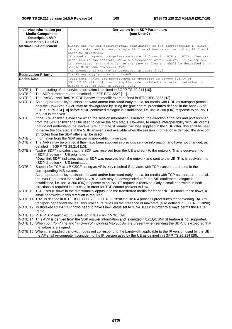
ETSI
ETSI TS 129 213 V14.5.0 (2017-10)1083GPP TS 29.213 version 14.5.0 Release 14
service information per Media-Component-
Description AVP (see notes 1 and 7)
Derivation from SDP Parameters (see Note 2)
Media-Sub-Component Supply one AVP for bidirectional combination of two corresponding IP flows, if available, and for each single IP flow without a corresponding IP flow in opposite direction. If a media component comprises separate IP flows for RTP and RTCP, they are described in two separate Media-Sub-Component AVPs. However, if a=rtcp-mux is negotiated, RTP and RTCP use the same IP flow and shall be described in a single Media-Sub-Component AVP. The encoding of the AVP is described in Table 6.2.2
Reservation-Priority The AF may supply or omit this AVP.
Codec-Data Codec Data AVP(s) are provisioned as specified in clause 5.3.16 of 3GPP TS 29.214 [10], including the codec-related information detailed in clause 5.3.7 of 3GPP TS 29.214 [10].
NOTE 1: The encoding of the service information is defined in 3GPP TS 29.214 [10]. NOTE 2: The SDP parameters are described in IETF RFC 2327 [11]. NOTE 3: The "b=RS:" and "b=RR:" SDP bandwidth modifiers are defined in IETF RFC 3556 [13]. NOTE 4: As an operator policy to disable forward and/or backward early media, for media with UDP as transport protocol
only the Flow-Status AVP may be downgraded by using the gate control procedures defined in the annex A of 3GPP TS 29.214 [10] before a SIP confirmed dialogue is established, i.e. until a 200 (OK) response to an INVITE request is received.
NOTE 5: If the SDP answer is available when the session information is derived, the direction attributes and port number from the SDP answer shall be used to derive the flow status. However, to enable interoperability with SIP clients that do not understand the inactive SDP attribute, if "a=inactive" was supplied in the SDP offer, this shall be used to derive the flow status. If the SDP answer is not available when the session information is derived, the direction attributes from the SDP offer shall be used.
NOTE 6: Information from the SDP answer is applicable, if available. NOTE 7: The AVPs may be omitted if they have been supplied in previous service information and have not changed, as
detailed in 3GPP TS 29.214 [10]. NOTE 8: "Uplink SDP" indicates that the SDP was received from the UE and sent to the network. This is equivalent to
<SDP direction> = UE originated. "Downlink SDP" indicates that the SDP was received from the network and sent to the UE. This is equivalent to <SDP direction> = UE terminated.
NOTE 9: Support for TCP at a P-CSCF acting as AF is only required if services with TCP transport are used in the corresponding IMS system. As an operator policy to disable forward and/or backward early media, for media with TCP as transport protocol, the Max-Requested-Bandwidth-UL/DL values may be downgraded before a SIP confirmed dialogue is established, i.e. until a 200 (OK) response to an INVITE request is received. Only a small bandwidth in both directions is required in this case in order for TCP control packets to flow.
NOTE 10: TCP uses IP flows in the directionality opposite to the transferred media for feedback. To enable these flows, a small bandwidth in this direction is required.
NOTE 11: TIAS is defined in IETF RFC 3890 [23]. IETF RFC 3890 clause 6.4 provides procedures for converting TIAS to transport-dependant values. This procedure relies on the presence of maxprate (also defined in IETF RFC 3890).
NOTE 12: Multiplexed RTP/RTCP flows need to have Flow-Status set to "ENABLED" in order to always permit the RTCP traffic.
NOTE 13: RTP/RTCP multiplexing is defined in IETF RFC 5761 [39]. NOTE 14: This AVP is derived from the SDP answer information and is omitted if E2EQOSMTSI feature is not supported. NOTE 15: When both "b =" line and "a=bw-info" including MaxSupBw are present when sending the SDP, it is expected that
the values are aligned. NOTE 16: When the supplied bandwidth does not correspond to the bandwidth applicable to the IP version used by the UE,
the AF shall re-compute it considering the IP version used by the UE as defined in 3GPP TS 26.114 [29].

ETSI
ETSI TS 129 213 V14.5.0 (2017-10)1093GPP TS 29.213 version 14.5.0 Release 14
Table 6.2.2: Rules for derivation of Media-Sub-Component AVP from SDP media component

ETSI
ETSI TS 129 213 V14.5.0 (2017-10)1103GPP TS 29.213 version 14.5.0 Release 14
service information per Media-Sub-Component
AVP (see notes 1 and 5)
Derivation from SDP Parameters (see Note 2)
Flow-Number The AF shall assign a number to the media-subcomponent AVP that is unique within the surrounding media component AVP and for the entire lifetime of the AF session. The AF shall select the ordinal number of the IP flow(s) within the "m=" line assigned in the order of increasing downlink destination port numbers, if downlink destination port numbers are available. For uplink or inactive unicast media IP flows, a downlink destination port number is nevertheless available, if SDP offer-answer according to IETF RFC 3264 is used. The AF shall select the ordinal number of the IP flow(s) within the "m=" line assigned in the order of increasing uplink destination port numbers, if no downlink destination port numbers are available.
Flow-Status AVP not supplied
Max-Requested-Bandwidth-UL
AVP not supplied
Max-Requested-Bandwidth-DL
AVP not supplied

ETSI
ETSI TS 129 213 V14.5.0 (2017-10)1113GPP TS 29.213 version 14.5.0 Release 14
Flow-Description For uplink and downlink direction, a Flow-Description AVP shall be provided unless no IP Flows in this direction are described within the media component. If UDP is used as transport protocol, the SDP direction attribute (NOTE 4) indicates the direction of the media IP flows within the media component as follows: IF a=recvonly THEN (NOTE 3) IF <SDP direction> = UE originated (NOTE 7) THEN Provide only downlink Flow-Description AVP ELSE /* UE terminated (NOTE 7) */ Provide only uplink Flow-Description AVP ENDIF; ELSE IF a=sendonly THEN (NOTE 3) IF <SDP direction> = UE originated (NOTE 7) THEN Provide only uplink Flow-Description AVP ELSE /* UE terminated (NOTE 7) */ Provide only downlink Flow-Description AVP ENDIF; ELSE /* a=sendrecv or a=inactive or no direction attribute */ Provide uplink and downlink Flow-Description AVPs ENDIF; ENDIF; However, for RTCP and RTP/RTCP multiplexed IP flows uplink and downlink Flow-Description AVPs shall be provided irrespective of the SDP direction attribute. If TCP is used as transport protocol (NOTE 8), IP flows in uplink and downlink direction are described in SDP irrespective of the SDP direction attribute, as TCP uses an IP flow for feedback even if contents are transferred only in the opposite direction. Thus, both uplink and downlink Flow-Description AVPs shall be provided. The uplink destination address shall be copied from the "c=" line of downlink SDP. (NOTE 6) (NOTE 7) The uplink destination port shall be derived from the "m=" line of downlink SDP. (NOTE 6) (NOTE 7) However, for TCP transport the uplink destination port shall be wildcarded, if the local UE is the passive endpoint (NOTE 9) The downlink destination address shall be copied from the "c=" line of uplink SDP. (NOTE 6) However, a P-CSCF acting as AF and applying NAT traversal procedures in Annex C shall derive the downlink destination address using those procedures. The downlink destination port shall be derived from the "m=" line of uplink SDP. (NOTE 6) (NOTE 7) However, for TCP transport the downlink destination port shall be wildcarded, if the local UE is the active endpoint (NOTE 9). A P-CSCF acting as AF and applying NAT traversal procedures in Annex C shall derive the downlink destination port using those procedures. For IPv6, uplink and downlink source addresses shall either be derived from the prefix of the destination address or be wildcarded by setting to "any", as specified in 3GPP TS 29.214 [10]. However, a P-CSCF acting as AF and applying NAT traversal procedures in Annex C shall derive the uplink source address using those procedures. If IPv4 is being utilized, the uplink source address shall either be set to the address contained in the "c=" line of the uplink SDP or be wildcared, and the downlink source address shall either be set to the address contained in the "c=" line of the downlink SDP or be wildcarded. However, for TCP transport, if the local UE is the passive endpoint (NOTE 9), the uplink source address shall not be wildcarded. If the local UE is the active endpoint (NOTE 9), the downlink source address shall not be wildcarded. A P-CSCF acting as AF and applying NAT traversal procedures in Annex C shall derive the uplink source address using those procedures. Source ports shall not be supplied. However, for TCP transport, if the local UE is the passive end point (NOTE 9), the uplink source port shall be derived from the "m=" line of the uplink SDP. If the local UE is the active end point (NOTE 9), the downlink source port shall be derived from the "m=" line of the downlink SDP. A P-CSCF acting as AF and applying NAT traversal procedures in Annex C shall derive the downlink source ports using those procedures. Proto shall be derived from the transport of the "m=" line. For "RTP/AVP" proto is 17(UDP). For "TCP", as defined in IETF RFC 4145 [16], or "TCP/MSRP", as defined in IETF RFC 4975 [17], proto is 6(TCP).
Flow-Usage The Flow-Usage AVP shall be supplied with value "RTCP" if the IP flow(s) described in the Media-Sub-Component AVP are used to transport RTCP only.
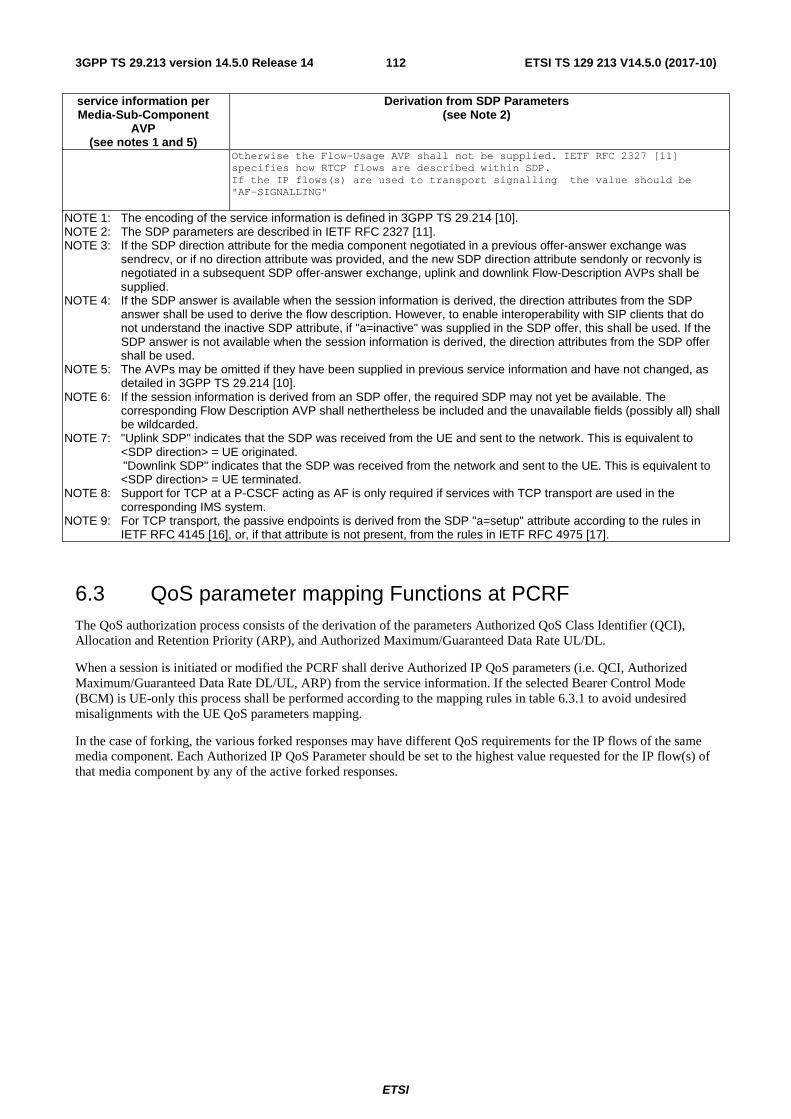
ETSI
ETSI TS 129 213 V14.5.0 (2017-10)1123GPP TS 29.213 version 14.5.0 Release 14
service information per Media-Sub-Component
AVP (see notes 1 and 5)
Derivation from SDP Parameters (see Note 2)
Otherwise the Flow-Usage AVP shall not be supplied. IETF RFC 2327 [11] specifies how RTCP flows are described within SDP. If the IP flows(s) are used to transport signalling the value should be "AF-SIGNALLING"
NOTE 1: The encoding of the service information is defined in 3GPP TS 29.214 [10]. NOTE 2: The SDP parameters are described in IETF RFC 2327 [11]. NOTE 3: If the SDP direction attribute for the media component negotiated in a previous offer-answer exchange was
sendrecv, or if no direction attribute was provided, and the new SDP direction attribute sendonly or recvonly is negotiated in a subsequent SDP offer-answer exchange, uplink and downlink Flow-Description AVPs shall be supplied.
NOTE 4: If the SDP answer is available when the session information is derived, the direction attributes from the SDP answer shall be used to derive the flow description. However, to enable interoperability with SIP clients that do not understand the inactive SDP attribute, if "a=inactive" was supplied in the SDP offer, this shall be used. If the SDP answer is not available when the session information is derived, the direction attributes from the SDP offer shall be used.
NOTE 5: The AVPs may be omitted if they have been supplied in previous service information and have not changed, as detailed in 3GPP TS 29.214 [10].
NOTE 6: If the session information is derived from an SDP offer, the required SDP may not yet be available. The corresponding Flow Description AVP shall nethertheless be included and the unavailable fields (possibly all) shall be wildcarded.
NOTE 7: "Uplink SDP" indicates that the SDP was received from the UE and sent to the network. This is equivalent to <SDP direction> = UE originated. "Downlink SDP" indicates that the SDP was received from the network and sent to the UE. This is equivalent to <SDP direction> = UE terminated.
NOTE 8: Support for TCP at a P-CSCF acting as AF is only required if services with TCP transport are used in the corresponding IMS system.
NOTE 9: For TCP transport, the passive endpoints is derived from the SDP "a=setup" attribute according to the rules in IETF RFC 4145 [16], or, if that attribute is not present, from the rules in IETF RFC 4975 [17].
6.3 QoS parameter mapping Functions at PCRF The QoS authorization process consists of the derivation of the parameters Authorized QoS Class Identifier (QCI), Allocation and Retention Priority (ARP), and Authorized Maximum/Guaranteed Data Rate UL/DL.
When a session is initiated or modified the PCRF shall derive Authorized IP QoS parameters (i.e. QCI, Authorized Maximum/Guaranteed Data Rate DL/UL, ARP) from the service information. If the selected Bearer Control Mode (BCM) is UE-only this process shall be performed according to the mapping rules in table 6.3.1 to avoid undesired misalignments with the UE QoS parameters mapping.
In the case of forking, the various forked responses may have different QoS requirements for the IP flows of the same media component. Each Authorized IP QoS Parameter should be set to the highest value requested for the IP flow(s) of that media component by any of the active forked responses.

ETSI
ETSI TS 129 213 V14.5.0 (2017-10)1133GPP TS 29.213 version 14.5.0 Release 14
Table 6.3.1: Rules for derivation of the Maximum Authorized Data Rates, Authorized Guaranteed Data Rates
and Maximum Authorized QoS Class per IP flow or bidirectional combination of IP flows in the PCRF

ETSI
ETSI TS 129 213 V14.5.0 (2017-10)1143GPP TS 29.213 version 14.5.0 Release 14
Authorized IP QoS Parameter
Derivation from service information (see Note 4)

ETSI
ETSI TS 129 213 V14.5.0 (2017-10)1153GPP TS 29.213 version 14.5.0 Release 14
Maximum Authorized Data Rate DL (Max_DR_DL) and UL (Max_DR_UL)
IF operator special policy exists THEN Max_DR_UL:= as defined by operator specific algorithm; Max_DR_DL:= as defined by operator specific algorithm; ELSE IF AF-Application-Identifier AVP demands application specific data rate handling THEN Max_DR_UL:= as defined by application specific algorithm; Max_DR_DL:= as defined by application specific algorithm; ELSE IF Codec-Data AVP provides Codec information for a codec that is supported by a specific algorithm (NOTE 19,20) THEN Max_DR_UL:= as defined by specific algorithm; Max_DR_DL:= as defined by specific algorithm; ELSE IF not RTCP flow(s) according to Flow-Usage AVP THEN IF Flow-Status = REMOVED THEN Max_DR_UL:= 0; Max_DR_DL:= 0; ELSE IF uplink Flow Description AVP is supplied THEN IF Max-Supported-Bandwidth-UL is present and supported THEN Max_DR_UL:= Max-Supported-Bandwidth-UL; ELSE IF Max-Requested-Bandwidth-UL is present THEN Max_DR_UL:= Max-Requested-Bandwidth-UL ; ELSE Max_DR_UL:= as set by the operator; ENDIF; ELSE Max_DR_UL:= 0; ENDIF; IF downlink Flow Description AVPs is supplied THEN IF Max-Supported-Bandwidth-DL is present and supported THEN Max_DR_DL:= Max-Supported-Bandwidth-DL; ELSE IF Max-Requested-Bandwidth-DL is present THEN Max_DR_DL:= Max-Requested-Bandwidth-DL; ELSE Max_DR_DL:= as set by the operator; ENDIF; ELSE Max_DR_DL:= 0; ENDIF; ENDIF; ELSE /* RTCP IP flow(s) */ IF RS-Bandwidth is present and RR-Bandwidth is present THEN Max_DR_UL:= (RS-Bandwidth + RR-Bandwidth); Max_DR_DL:= (RS-Bandwidth + RR-Bandwidth); ELSE IF Max-Requested-Bandwidth-UL is present THEN IF RS-Bandwidth is present and RR-Bandwidth is not present THEN Max_DR_UL:= MAX[0.05 * Max-Requested-Bandwidth-UL,RS-Bandwidth]; ENDIF; IF RS-Bandwidth is not present and RR-Bandwidth is present THEN Max_DR_UL:= MAX[0.05 * Max-Requested-Bandwidth-UL,RR-Bandwidth]; ENDIF; IF RS-Bandwidth and RR-Bandwidth are not present THEN Max_DR_UL:= 0.05 * Max-Requested-Bandwidth_UL ; ENDIF; ELSE Max_DR_UL:= as set by the operator; ENDIF; IF Max-Requested-Bandwidth-DL is present THEN IF RS-Bandwidth is present and RR-Bandwidth is not present THEN Max_DR_DL:= MAX[0.05 * Max-Requested-Bandwidth-DL,RS-Bandwidth]; ENDIF; IF RS-Bandwidth is not present and RR-Bandwidth is present THEN Max_DR_DL:= MAX[0.05 * Max-Requested-Bandwidth-DL,RR-Bandwidth]; ENDIF;
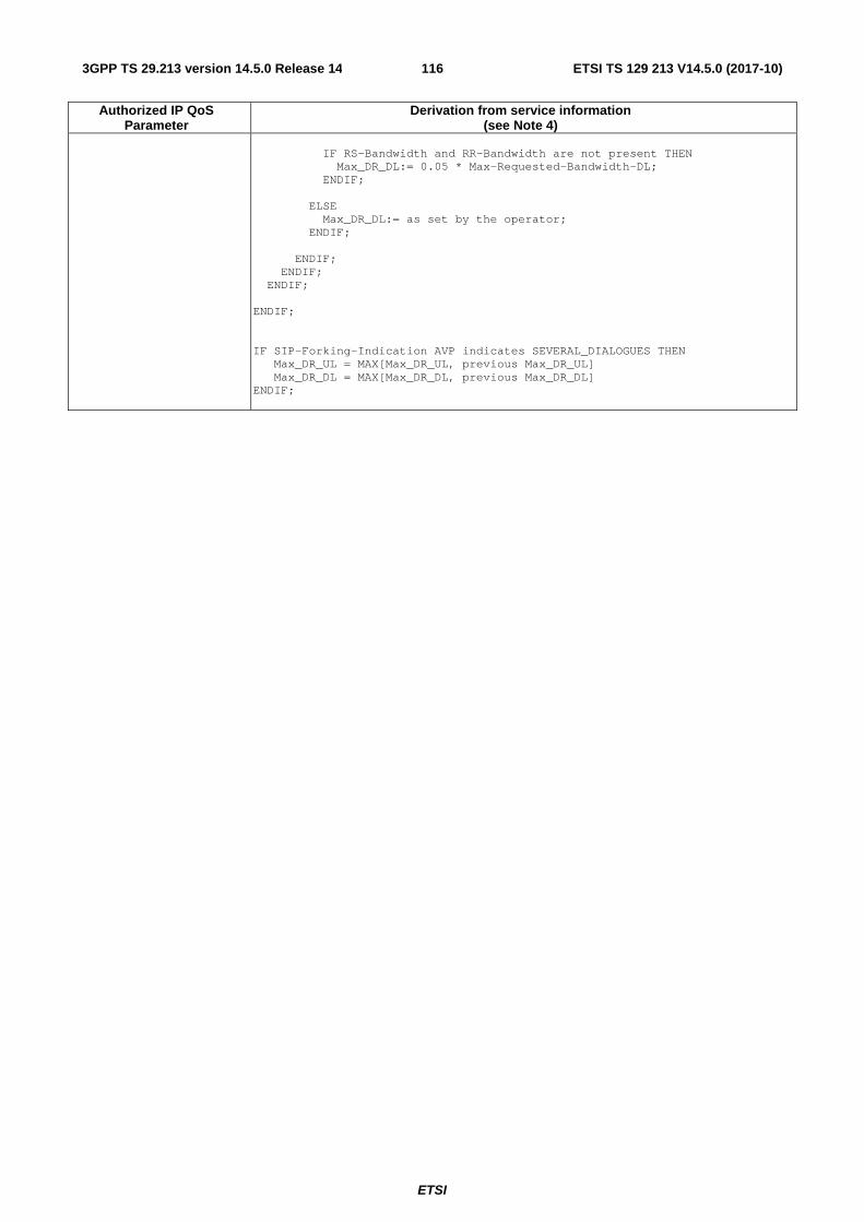
ETSI
ETSI TS 129 213 V14.5.0 (2017-10)1163GPP TS 29.213 version 14.5.0 Release 14
Authorized IP QoS Parameter
Derivation from service information (see Note 4)
IF RS-Bandwidth and RR-Bandwidth are not present THEN Max_DR_DL:= 0.05 * Max-Requested-Bandwidth-DL; ENDIF; ELSE Max_DR_DL:= as set by the operator; ENDIF; ENDIF; ENDIF; ENDIF; ENDIF; IF SIP-Forking-Indication AVP indicates SEVERAL_DIALOGUES THEN Max_DR_UL = MAX[Max_DR_UL, previous Max_DR_UL] Max_DR_DL = MAX[Max_DR_DL, previous Max_DR_DL] ENDIF;

ETSI
ETSI TS 129 213 V14.5.0 (2017-10)1173GPP TS 29.213 version 14.5.0 Release 14
Authorized IP QoS Parameter
Derivation from service information (see Note 4)
Authorized Guaranteed Data Rate DL (Gua_DR_DL) and UL (Gua_DR_UL) (see NOTE 11, 13, 15, 16)
IF operator special policy exists THEN Gua_DR_UL:= as defined by operator specific algorithm; Gua_DR_DL:= as defined by operator specific algorithm; ELSE IF AF-Application-Identifier AVP demands application specific data rate handling THEN Gua_DR_UL:= as defined by application specific algorithm; Gua_DR_DL:= as defined by application specific algorithm; ELSE IF Codec-Data AVP provides Codec information for a codec that is supported by a specific algorithm (NOTE 5,19,20)THEN Gua_DR_UL:= as defined by specific algorithm; Gua_DR_DL:= as defined by specific algorithm; ELSE IF uplink Flow-Description AVP is supplied THEN IF Min-Desired-Bandwidth-UL is present and supported THEN Gua_DR_UL:= Min-Desired-Bandwidth-UL ; ELSE IF Min-Requested-Bandwidth-UL is present THEN Gua_DR_UL:= Min-Requested-Bandwidth-UL ; ELSE Gua_DR_UL:= as set by the operator; ENDIF; ELSE Gua_DR_UL:= Max DR UL; ENDIF; IF downlink Flow-Description AVP is supplied THEN IF Min-Desired-Bandwidth-DL is present and supported THEN Gua_DR_DL:= Min-Desired-Bandwidth-DL ELSE IF Min-Requested-Bandwidth-DL is present THEN Gua_DR_DL:= Min-Requested-Bandwidth-DL ; ELSE Gua_DR_DL:= as set by the operator; ENDIF; ELSE Gua_DR_DL:= Max DR DL; ENDIF; ENDIF; ENDIF; IF SIP-Forking-Indication AVP indicates SEVERAL_DIALOGUES THEN Gua_DR_UL = MAX[Gua_DR_UL, previous Gua_DR_UL] Gua_DR_DL = MAX[Gua_DR_DL, previous Gua_DR_DL] ENDIF;

ETSI
ETSI TS 129 213 V14.5.0 (2017-10)1183GPP TS 29.213 version 14.5.0 Release 14
Authorized IP QoS Parameter
Derivation from service information (see Note 4)
Authorized QoS Class Identifier [QCI] (see NOTE 1, 2, 7, 12 and 14)
IF an operator special policy exists THEN QCI:= as defined by operator specific algorithm; ELSE IF MPS-Identifier AVP demands MPS specific QoS Class handling THEN QCI:= as defined by MPS specific algorithm (NOTE 18); ELSE IF GCS-Identifier AVP demands Group Communication specific handling THEN QCI:= as defined by GCS specific algorithm (NOTE 17); ELSE IF AF-Application-Identifier AVP demands application specific QoS Class handling THEN QCI:= as defined by application specific algorithm; ELSE IF Codec-Data AVP provides Codec information for a codec that is supported by a specific algorithm THEN QCI:= as defined by specific algorithm; (NOTE 5) ELSE /* The following QCI derivation is an example of how to obtain the QCI values in a GPRS network */ IF Media-Type is present THEN /* for GPRS: streaming */ IF (only uplink Flow Description AVPs are supplied for all IP flows of the AF session, which have media type “audio” or “video” and no flow usage “RTCP”, or only downlink Flow Desription AVPs are supplied for all IP flows of the AF session, which have media type “audio” or “video” and no flow usage “RTCP”) THEN CASE Media-Type OF “audio”: MaxClassDerivation := 3 OR 4; (NOTE 9) “video”: MaxClassDerivation := 4 END; /* for GPRS: conversational */ ELSE CASE Media-Type OF “audio”: MaxClassDerivation:= 1 OR 2; (NOTE 6) “video”: MaxClassDerivation:= 2 END; ENDIF; CASE Media-Type OF “audio”: QCI := MaxClassDerivation “video”: QCI := MaxClassDerivation “application”: QCI := 1 OR 2; (NOTE 6) /*e.g. for GPRS: conversational*/ “data”: QCI := 6 OR 7 OR 8; (NOTE 8) /*e.g. for GPRS: interactive with prio 1, 2 AND 3 respectively*/ “control”: QCI := 6; /*e.g. for GPRS: interactive with priority 1*/ /* NOTE: include new media types here */ OTHERWISE: QCI := 9; /*e.g. for GPRS: background*/ END; ENDIF; ENDIF; IF SIP-Forking-Indication AVP indicates SEVERAL_DIALOGUES THEN QCI = MAX[QCI, previous QCI](NOTE 10) ENDIF ;

ETSI
ETSI TS 129 213 V14.5.0 (2017-10)1193GPP TS 29.213 version 14.5.0 Release 14
Authorized IP QoS Parameter
Derivation from service information (see Note 4)
NOTE 1: The QCI assigned to a RTCP IP flow is the same as for the corresponding RTP media IP flow. NOTE 2: When audio or video IP flow(s) are removed from a session, the parameter MaxClassDerivation shall keep the
originally assigned value. NOTE 3: When audio or video IP flow(s) are added to a session, the PCRF shall derive the parameter MaxClassDerivation
taking into account the already existing media IP flow(s) within the session. NOTE 4: The encoding of the service information is defined in 3GPP TS 29.214 [10]. Possible Bandwidth information and
Flow-Status information provided within the Media-Sub-Component AVP takes precedence over information within the encapsulating Media-Component-Description AVP as specified in 3GPP TS 29.214 [10]. If AVPs are omitted within a Media-Component-Description AVP or Media-Sub-Component AVP of the service information, the corresponding information from previous service information shall be used, as specified in 3GPP TS 29.214 [10].
NOTE 5: 3GPP TS 26.234 [6], 3GPP TS 26.114 [29], 3GPP2 C.S0046 [18], and 3GPP2 C.S0055 [19] contain examples of QoS parameters for codecs of interest. The support of any codec specific algorithm in the PCRF is optional.
NOTE 6: The final QCI value will depend on the value of SSID (speech/unknown) according to 3GPP TS 23.107 [4]. If the PCRF is not able to determine the SSID, it should use the QCI value 2 that corresponds to SSID unknown. For UE-init and mixed mode, the PCRF may derive from the requested QoS of an IP CAN bearer which SSID is applicable.
NOTE 7: The numeric value of the QCI are based on 3GPP TS 29.212 [9]. NOTE 8: The QCI value also encodes the traffic handling priority for GPRS. If the PCRF is not able to determine a traffic
handling priority, it should choose QCI 8 that corresponds to priority 3. Also, for UE-initiated bearers the PCRF should only use QCI 8 in order to have the same mapping rules in both UE and PCRF.
NOTE 9: The final QCI value will depend on the value of SSID (speech/unknown) according to 3GPP TS 23.107 [4]. If the PCRF is not able to determine the SSID, it should use the QCI value 4 that corresponds to SSID unknown. For UE-init and mixed mode, the PCRF may derive from the requested QoS of an IP CAN bearer which SSID is applicable.
NOTE 10: The Max function shall use the following precedence order for the QCI values: 2 > 1 > 4 > 3 > 5 > 6 > 7 > 8 > 9 NOTE 11: Authorized Guaranteed Data Rate DL and UL shall not be derived for QCI values 5, 6, 7, 8 and 9. NOTE 12: Recommended QCI values for standardised QCI characteristics are shown in table 6.1.7 in 3GPP TS 23.203 [2]. NOTE 13: The PCRF may be configured with operator specific preconditions for setting the Authorized Guaranteed Data
Rate lower than the corresponding Maximum Authorized Data Rate. NOTE 14: In a network where SRVCC is enabled, the QCI=1 shall be used for IMS services in accordance to
3GPP TS 23.216 [27]. Non-IMS services using QCI=1 may suffer service interruption and/or inconsistent service experience if SRVCC is triggered. Triggering SRVCC for WebRTC IMS session will cause service interruption and/or inconsistent service experience when using QCI=1. Operator policy (e.g. use of specific AF application identifier) may be used to avoid using QCI 1 for a voice service, e.g. WebRTC IMS session.
NOTE 15: For certain services (e.g. DASH services according to 3GPP TS 26.247 [30]), the AF may also provide a minimum required bandwidth so that the PCRF can derive an Authorized Guaranteed Data Rate lower than the Maximum Authorized Data Rate.
NOTE 16: For GPRS and EPS, the PCRF shall assign an Authorized Guaranteed Data Rate UL/DL value within the limit supported by the serving network.
NOTE 17: The GCS specific algorithm shall consider various inputs, including the received Reservation-Priority AVP, for deriving the QCI.
NOTE 18: The MPS specific algorithm shall consider various inputs, including the received MPS-Identifier AVP and Reservation-Priority AVP, for deriving the QCI.
NOTE 19: When multiple codecs are supported per media stream (e.g. as part of multi-stream multiparty conferencing media handling are negotiated as described in 3GPP TS 26.114 [29]) the codec specific algorithm shall consider the bandwidth related to each codec when calculating the total bandwidth.
NOTE 20: 3GPP TS 26.114 [29] contains examples of how the Authorized Guaranteed Data Rate and Maximum Authorized Data Rate are assumed to be derived for multi-party multimedia conference media handling support. The support of this behaviour is optional.
The PCRF should per ongoing session store the Authorized IP QoS parameters per for each IP flow or bidirectional combination of IP flows (as described within a Media Subcomponent AVP).
If the PCRF provides a QoS-Information AVP within a Charging-Rule-Definition AVP it may apply the rules in table 6.3.2 to combine the Authorized QoS per IP flow or bidirectional combination of IP flows (as derived according to table 6.3.1) for all IP flows described by the corresponding PCC rule.
If the PCRF provides a QoS-Information AVP for an entire IP CAN bearer (for a UE-initiated IP-CAN bearer in the GPRS case) or IP CAN session, it may apply the rules in table 6.3.2 to combine the Authorized QoS per IP flow or bidirectional combination of IP flows (as derived according to table 6.3.1) for all IP flows allowed to be transported within the IP CAN bearer or session. It is recommended that the rules in table 6.3.2 are applied for all IP flows with corresponding AF session. The PCRF may increase the authorized QoS further to take into account the requirements of predefined PCC rules without ongoing AF sessions.
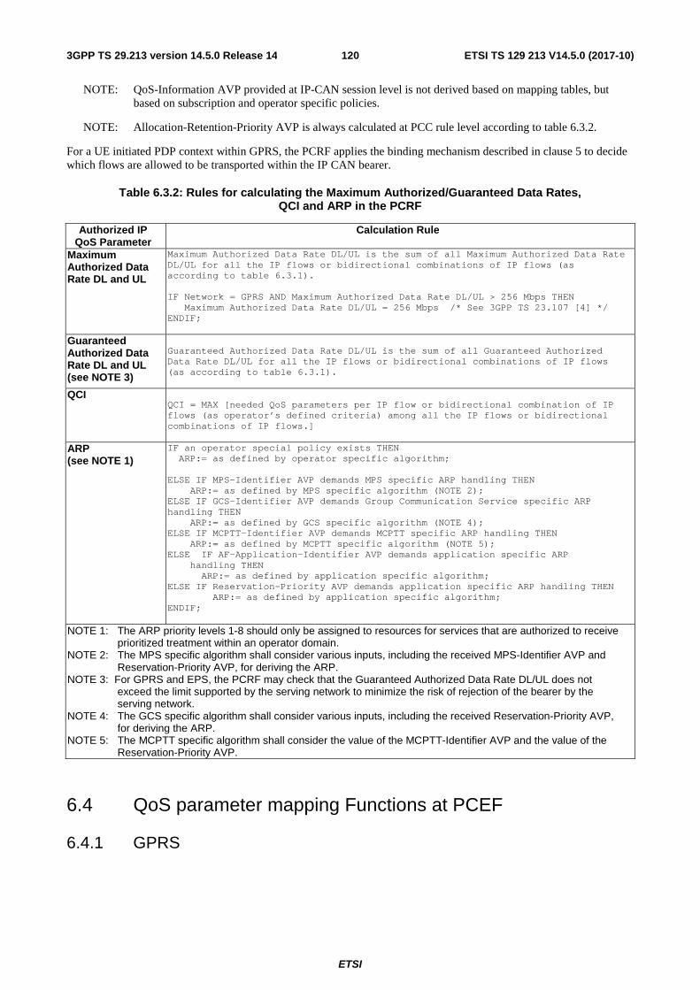
ETSI
ETSI TS 129 213 V14.5.0 (2017-10)1203GPP TS 29.213 version 14.5.0 Release 14
NOTE: QoS-Information AVP provided at IP-CAN session level is not derived based on mapping tables, but based on subscription and operator specific policies.
NOTE: Allocation-Retention-Priority AVP is always calculated at PCC rule level according to table 6.3.2.
For a UE initiated PDP context within GPRS, the PCRF applies the binding mechanism described in clause 5 to decide which flows are allowed to be transported within the IP CAN bearer.
Table 6.3.2: Rules for calculating the Maximum Authorized/Guaranteed Data Rates, QCI and ARP in the PCRF
Authorized IP QoS Parameter
Calculation Rule
Maximum Authorized Data Rate DL and UL
Maximum Authorized Data Rate DL/UL is the sum of all Maximum Authorized Data Rate DL/UL for all the IP flows or bidirectional combinations of IP flows (as according to table 6.3.1). IF Network = GPRS AND Maximum Authorized Data Rate DL/UL > 256 Mbps THEN Maximum Authorized Data Rate DL/UL = 256 Mbps /* See 3GPP TS 23.107 [4] */ ENDIF;
Guaranteed Authorized Data Rate DL and UL (see NOTE 3)
Guaranteed Authorized Data Rate DL/UL is the sum of all Guaranteed Authorized Data Rate DL/UL for all the IP flows or bidirectional combinations of IP flows (as according to table 6.3.1).
QCI QCI = MAX [needed QoS parameters per IP flow or bidirectional combination of IP flows (as operator’s defined criteria) among all the IP flows or bidirectional combinations of IP flows.]
ARP (see NOTE 1)
IF an operator special policy exists THEN ARP:= as defined by operator specific algorithm; ELSE IF MPS-Identifier AVP demands MPS specific ARP handling THEN ARP:= as defined by MPS specific algorithm (NOTE 2); ELSE IF GCS-Identifier AVP demands Group Communication Service specific ARP handling THEN ARP:= as defined by GCS specific algorithm (NOTE 4); ELSE IF MCPTT-Identifier AVP demands MCPTT specific ARP handling THEN ARP:= as defined by MCPTT specific algorithm (NOTE 5); ELSE IF AF-Application-Identifier AVP demands application specific ARP handling THEN ARP:= as defined by application specific algorithm; ELSE IF Reservation-Priority AVP demands application specific ARP handling THEN ARP:= as defined by application specific algorithm; ENDIF;
NOTE 1: The ARP priority levels 1-8 should only be assigned to resources for services that are authorized to receive prioritized treatment within an operator domain.
NOTE 2: The MPS specific algorithm shall consider various inputs, including the received MPS-Identifier AVP and Reservation-Priority AVP, for deriving the ARP.
NOTE 3: For GPRS and EPS, the PCRF may check that the Guaranteed Authorized Data Rate DL/UL does not exceed the limit supported by the serving network to minimize the risk of rejection of the bearer by the serving network.
NOTE 4: The GCS specific algorithm shall consider various inputs, including the received Reservation-Priority AVP, for deriving the ARP.
NOTE 5: The MCPTT specific algorithm shall consider the value of the MCPTT-Identifier AVP and the value of the Reservation-Priority AVP.
6.4 QoS parameter mapping Functions at PCEF
6.4.1 GPRS

ETSI
ETSI TS 129 213 V14.5.0 (2017-10)1213GPP TS 29.213 version 14.5.0 Release 14
6.4.1.1 Authorized IP QoS parameters per PDP Context to Authorized UMTS QoS parameters mapping in GGSN
The Translation/Mapping function in the GGSN shall derive the Authorized UMTS QoS parameters from the Authorized IP QoS parameters received from the PCRF according to the rules in table 6.4.1.

ETSI
ETSI TS 129 213 V14.5.0 (2017-10)1223GPP TS 29.213 version 14.5.0 Release 14
Table 6.4.1: Rules for derivation of the Authorized UMTS QoS Parameters per PDP context from the Authorized IP QoS Parameters in GGSN
Authorized UMTS QoS Parameter per
PDP context
Derivation from Authorized IP QoS Parameters
Maximum Authorized Bandwidth DL and UL per PDP context (see NOTE 2)
Maximum Authorized Bandwidth DL/UL per PDP context = Maximum Authorized Data Rate DL/UL
Guaranteed Authorized Data Rate DL and UL per PDP context
Guaranteed Authorized Data Rate DL/UL per PDP context = Guaranteed Authorized Data Rate DL/UL
Maximum Authorized Traffic Class per PDP context
IF QCI = 1 OR 2 THEN Maximum Authorized Traffic Class = “Conversational” ELSEIF QCI = 3 OR 4 THEN Maximum Authorized Traffic Class = “Streaming” ELSEIF QCI = 5 OR 6 OR 7 OR 8 THEN Maximum Authorized Traffic Class = “Interactive”; ELSE Maximum Authorized Traffic Class = “Background” ENDIF ;
Traffic Handling Priority
IF QCI = 5 OR 6 THEN Maximum Authorized Traffic Handling Priority = “1”; ELSE IF QCI = 7 THEN Maximum Authorized Traffic Handling Priority = “2”; ELSE IF QCI = 8 THEN Maximum Authorized Traffic Handling Priority = “3”; ELSE the GGSN shall not derive Traffic Handling Priority ENDIF ;
Signalling Indication
IF QCI = 5 THEN Signalling Indication = “Yes”; ELSE IF QCI = 6 OR 7 OR 8 THEN Signalling Indication = “No”; ELSE the GGSN shall not derive Signalling Indication ENDIF ;
Source Statistics Descriptor
IF QCI = (1 OR 3) THEN Source Statistics Descriptor = “speech”; ELSE IF QCI = 2 OR 4 THEN Source Statistics Descriptor = “unknown”; ELSE the GGSN shall not derive Source Statistics Descriptor ENDIF ;
Evolved Allocation/Retention Priority (see NOTE 1)
Evolved Allocation/Retention Priority = Allocation-Retention-Priority as follows : PL := Priority-Level ; PVI := Pre-emption-Vulnerability ; PCI := Pre-emption-Capability ;
APN-AMBR UL and DL
For non-GBR PDP Contexts, APN-AMBR DL/UL = APN-Aggregate-Max-Bitrate DL/UL
NOTE 1: Evolved Allocation/Retention Priority is derived only if supported by the SGSN. NOTE 2: When APN-AMBR is supported in GPRS and the PCEF performs the bearer binding, the MBR for non-GBR PDP-Contexts is not derived

ETSI
ETSI TS 129 213 V14.5.0 (2017-10)1233GPP TS 29.213 version 14.5.0 Release 14
6.4.1.2 Comparing UMTS QoS Parameters against the Authorized UMTS QoS parameters in GGSN for UE initiated PDP context
Upon receiving a PDP context activation, the GGSN requests PCC rules from the PCRF (see 3GPP TS 29.212 [9] for details). The PCRF may supply Authorized IP QoS Parameters per PDP context together with the PCC rules. The GGSN maps the Authorized IP QoS parameters per PDP Context to Authorized UMTS QoS parameters according to subclause 6.4.1.1 and then compares the requested UMTS QoS parameters against the corresponding Authorized UMTS QoS parameters. The following criteria shall be fulfilled:
- If the requested Guaranteed Bitrate DL/UL (if the requested Traffic Class is Conversational or Streaming) is equal to the Authorized Guaranteed data rate DL/UL; and
- if received, the requested Maximum Bitrate DL/UL (if the requested Traffic Class is Interactive or Background) is equal to Maximum Authorized data rate DL/UL; and
- the requested Traffic Class is equal to Maximum Authorized Traffic Class; and.
- if received, the requested Evolved Allocation/Retention Priority is equal to Allocation-Retention-Priority.
- if received, the requested APN-AMBR DL/UL is equal to the APN-Aggregate-Max-Bitrate DL/UL.
Then, the GGSN shall accept the PDP context activation or modification with the UE requested parameters.Otherwise, the GGSN is adjusted (downgrade or upgrade) the requested UMTS QoS parameters to the values that were authorized.
6.4.2 3GPP- EPS
6.4.2.1 Authorized IP QoS parameters per PDP Context to Authorized UMTS QoS parameters mapping in P-GW.
This Translation/Mapping function in the P-GW applies when the P-GW interacts with a Gn/Gp SGSN.
The Translation/Mapping function in the P-GW shall derive the Authorized UMTS QoS parameters from the Authorized IP QoS parameters derived for the bearer applying the rules in table 6.4.2.

ETSI
ETSI TS 129 213 V14.5.0 (2017-10)1243GPP TS 29.213 version 14.5.0 Release 14
Table 6.4.2: Rules for derivation of the Authorized UMTS QoS Parameters per PDP context from the Authorized IP QoS Parameters in P-GW.

ETSI
ETSI TS 129 213 V14.5.0 (2017-10)1253GPP TS 29.213 version 14.5.0 Release 14
Authorized UMTS QoS Parameter per
PDP context
Derivation from Authorized IP QoS Parameters
Maximum Authorized Bandwidth DL and UL per PDP context (see NOTE 2)
For non-GBR bearers, Maximum Authorized Bandwidth DL/UL per PDP context = APN-Aggregate-Max-Bitrate DL/UL For GBR bearers, Maximum Authorized Bandwidth DL/UL per PDP context = Sum of Maximum Authorized Data Rate DL/UL for all PCC Rules bound to that bearer
Guaranteed Authorized Data Rate DL and UL per PDP context
Guaranteed Authorized Data Rate DL/UL per PDP context = Sum of Guaranteed Authorized Data Rate DL/UL for all PCC Rules bound to that bearer
Maximum Authorized Traffic Class per PDP context
IF QCI = 1 OR 2 OR 3 THEN Maximum Authorized Traffic Class = “Conversational” ELSEIF QCI = 4 THEN Maximum Authorized Traffic Class = “Streaming” ELSEIF QCI = 5 OR 6 OR 7 OR 8 THEN Maximum Authorized Traffic Class = “Interactive”; ELSE Maximum Authorized Traffic Class = “Background” ENDIF ;
Traffic Handling Priority
IF QCI = 5 OR 6 THEN Maximum Authorized Traffic Handling Priority = “1”; ELSE IF QCI = 7 THEN Maximum Authorized Traffic Handling Priority = “2”; ELSE IF QCI = 8 THEN Maximum Authorized Traffic Handling Priority = “3”; ELSE the P-GW shall not derive Traffic Handling Priority ENDIF ;
Signalling Indication
IF QCI = 5 THEN Signalling Indication = “Yes”; ELSE IF QCI = 6 OR 7 OR 8 THEN Signalling Indication = “No”; ELSE the P-GW shall not derive Signalling Indication ENDIF ;
Source Statistics Descriptor
IF QCI = 1 THEN Source Statistics Descriptor = “speech”; ELSE IF QCI = 2 OR 3 OR 4 THEN Source Statistics Descriptor = “unknown”; ELSE the P-GW shall not derive Source Statistics Descriptor ENDIF ;
APN-AMBR DL and UL (see NOTE 3)
For non-GBR bearers, APN-AMBR = APN-Aggregate-Max-Bitrate DL/UL
Transfer Delay (see NOTE 1)
IF QCI = 2 THEN Transfer Delay = 150 ms ELSE IF QCI = 3 THEN Transfer Delay >= 80 ms ELSE IF QCI = 1 OR 4 the P-GW shall set the Transfer Delay as the Packet Delay Budget for that QCI ELSE the P-GW shall not derive Transfer Delay. ENDIF ;

ETSI
ETSI TS 129 213 V14.5.0 (2017-10)1263GPP TS 29.213 version 14.5.0 Release 14
Evolved Allocation/Retention Priority (see NOTE 4)
Evolved Allocation/Retention Priority = Allocation-Retention-Priority as follows : PL := Priority-Level ; PVI := Pre-emption-Vulnerability ; PCI := Pre-emption-Capability ;
NOTE 1: Recommended Packet Delay Budget values for the different QCI values are defined in subclause 6.1.7,3GPP TS 23.203 [2].
NOTE 2: For non-GBR bearers, applicable only if APN-AMBR is not supported by the SGSN. NOTE 3: Applicable to all non-GBR PDP-Contexts when supported by the SGSN. NOTE 4: Evolved Allocation/Retention Priority is derived only if supported by the SGSN.
6.4.2.2 Comparing UMTS QoS Parameters against the Authorized UMTS QoS parameters in P-GW for UE initiated PDP context
Upon receiving a PDP context activation, the P-GW requests PCC rules from the PCRF (see 3GPP TS 29.212 [9] for details). The PCRF may supply Authorized IP QoS Parameters applicable for the provided PCC rules. The P-GW calculates the Authorized IP QoS parameters per bearer and maps the Authorized IP QoS parameters per bearer to Authorized UMTS QoS parameters according to subclause 6.4.2.1 and then compares the requested UMTS QoS parameters against the corresponding Authorized UMTS QoS parameters. The following criteria shall be fulfilled:
- If the requested Guaranteed Bitrate DL/UL (if the requested Traffic Class is Conversational or Streaming) is equal to the Authorized Guaranteed data rate DL/UL; and
- the requested Maximum Bitrate DL/UL (if the requested Traffic Class is Interactive or Background) is equal to Maximum Authorized data rate DL/UL; and
- the requested Traffic Class is equal to Maximum Authorized Traffic Class; and
- if received, the requested Evolved Allocation/Retention Priority is equal to Allocation-Retention-Priority.
Then, the P-GW shall accept the PDP context activation with the UE requested parameters. Otherwise, the P-GW shall accept the request and adjust (downgrade or upgrade) the requested UMTS QoS parameters to the values that were authorized.
6.5 QoS parameter mapping Functions at UE for a UE-initiated GPRS PDP Context
Figure 6.5.1 indicates the entities participating in the generation of the requested QoS parameters when the UE activates or modifies a PDP Context. The steps are:
1. The Application provides the UMTS BS Manager, possibly via the IP BS Manager and the Translation/Mapping function, with relevant information to perform step 2 or step 4. (Not subject to standardization within 3GPP).
2. If needed, information from step 1 is used to access a proper set of UMTS QoS Parameters. See 3GPP TS 26.114 [29] for Conversational Codec Applications and 3GPP TS 26.234 [6] for Streaming Codec Applications.
3. If SDP is available then the SDP Parameters should give guidance for the UMTS BS Manager (possibly via the IP Manager and the Translation/Mapping function) ,according to the rules in clause 6.5.1, to set the Maximum Bitrate UL/DL and the Guaranteed Bitrate UL/DL. Furthermore the Maximum Authorized Bandwidth UL/DL and Maximum Authorised Traffic Class should be derived according to the rules in clause 6.5.2.
4. A set of UMTS QoS Parameters values from step 2 (or directly from step 1) is possibly merged together with the Maximum Bitrate UL/DL and the Guaranteed Bitrate UL/DL from step 3. The result should constitute the requested UMTS QoS Parameters. The UE should check that the requested Guaranteed Bitrate UL/DL or requested Maximum Bitrate UL/DL (depending on the requested Traffic Class) does not exceed the Maximum Authorized Bandwidth UL/DL derived in step 3. Furthermore, if the UE has implemented the mapping rule for Maximum Authorized Traffic Class, as defined in clause 6.5.2, the UE should check that the requested Traffic Class does not exceed the Maximum Authorised Traffic Class derived in step 3.

ETSI
ETSI TS 129 213 V14.5.0 (2017-10)1273GPP TS 29.213 version 14.5.0 Release 14
Application
SDP Handler
UMTS BS Manager
Session Manager
SGSN
Session Manager
PDP Contex Activation and Modification
(SDP)UE
UMTS QoS
Param. Per
Applic Type
1)
2)
3)
4)
Translation / Mapping
IP BS Manager
Figure 6.5.1: Framework for generating requested QoS parameters in the UE

ETSI
ETSI TS 129 213 V14.5.0 (2017-10)1283GPP TS 29.213 version 14.5.0 Release 14
6.5.1 SDP to UMTS QoS parameter mapping in UE
If SDP Parameters are available, then before activating or modifying a PDP Context the UE should check if the SDP Parameters give guidance for setting the requested UMTS QoS Parameters. The UE should use the mapping rule in table 6.5.1.1 to derive the Maximum and Guaranteed Bitrate DL/UL from the SDP Parameters.
Table 6.5.1.1: Recommended rules for derivation of the requested Maximum and Guaranteed Bitrate DL/UL per media component in the UE
UMTS QoS Parameter per media component
Derivation from SDP Parameters
Maximum Bitrate DL/UL and Guaranteed Bitrate DL/UL per media component
/* Check if the media use codec(s) */ IF [(<media> = (“audio” or “video”)) and (<transport> = “RTP/AVP”)] THEN /* Check if Streaming */ IF a= (“sendonly” or “recvonly”) THEN Maximum Bitrate DL/UL and Guaranteed Bitrate DL/UL per media component as specified in 3GPP TS 26.234 [6] ; /* Conversational as default !*/ ELSE Maximum Bitrate DL/UL and Guaranteed Bitrate DL/UL per media component as specified in reference 3GPP TS 26.114 [29] ; ENDIF ; /* Check for presence of bandwidth attribute for each media component */ ELSEIF b=AS:<bandwidth-value> is present THEN IF media stream only downlink THEN Maximum Bitrate DL = Guaranteed Bitrate DL =<bandwidth-value >; ELSEIF mediastream only uplink THEN Maximum Bitrate UL = Guaranteed Bitrate UL =<bandwidth-value >; ELSEIF mediastreams both downlink and uplink THEN Maximum Bitrate DL = Guaranteed Bitrate DL =<bandwidth-value >; Maximum Bitrate UL = Guaranteed Bitrate UL =<bandwidth-value >; ENDIF; ELSE /* SDP does not give any guidance ! */ Maximum Bitrate DL/UL and Guaranteed Bitrate DL/UL per media component as specified by the UE manufacturer; ENDIF ;
6.5.2 SDP parameters to Authorized UMTS QoS parameters mapping in UE
If the PDP Context is activated or modified the UE should use the mapping rules in table 6.5.2.1 for all applications using SDP to derive the Maximum Authorized Bandwidth UL/DL per IP flow or bidirectional combinations of IP flows.
Table 6.5.2.1 also has a mapping rule for derivation of Maximum Authorized Traffic Class per IP flow or bidirectional combinations of IP flows which applies for session initiation and modification.
In future releases this mapping rule may change.
In the case of forking, the various forked responses may have different QoS requirements for the same IP flows of a media component. When the Authorized UMTS QoS Parameters are used by the UE, they shall be set equal to the highest values requested for the IP flows of that media component by any of the active forked responses. The UE should use the mapping rule in table 6.5.2.1 for each forked response.

ETSI
ETSI TS 129 213 V14.5.0 (2017-10)1293GPP TS 29.213 version 14.5.0 Release 14
Table 6.5.2.1: Rules for derivation of the Maximum Authorized Bandwidth DL/UL and the Maximum Authorized Traffic Class per IP flow or bidirectional combination of IP flows in the UE

ETSI
ETSI TS 129 213 V14.5.0 (2017-10)1303GPP TS 29.213 version 14.5.0 Release 14
Authorized UMTS QoS Parameter
Derivation from SDP Parameters (see Note 4)

ETSI
ETSI TS 129 213 V14.5.0 (2017-10)1313GPP TS 29.213 version 14.5.0 Release 14
Maximum Authorized Bandwidth DL (Max_BW_DL) and UL (Max_BW_UL) (see NOTE 5)
IF a=recvonly THEN IF <SDP direction> = mobile originated THEN Direction:= downlink; ELSE /* mobile terminated */ Direction:= uplink; ENDIF; ELSE /* a!= recvonly */ IF a=sendonly THEN IF <SDP direction> = mobile originated THEN Direction: = uplink; ELSE /* mobile terminated */ Direction:= downlink; ENDIF; ELSE /*sendrecv, inactive or no direction attribute*/ Direction:=both; ENDIF; ENDIF; /* Max_BW_UL and Max_BW_DL */ IF media IP flow(s) THEN IF bAS=AS:<bandwidth> is present and ( bTIAS=TIAS:<Tibandwidth> is not present or is present but not supported ) THEN IF Direction=downlink THEN Max_BW_UL:= 0; Max_BW_DL:= bAS; ELSE IF Direction=uplink THEN Max_BW_UL := bAS ; Max_BW_DL := 0 ; ELSE /*Direction=both*/ Max_BW_UL:= bAS; Max_BW_DL := bAS ; ENDIF ; ENDIF; ELSE IF bTIAS=TIAS:<Tibandwidth> is present and supported THEN bTDBW= bTIAS + transport-overhead; (NOTE 6) IF Direction=downlink THEN Max_BW_UL:= 0; Max_BW_DL:= bTDBW; (NOTE 6) ELSE IF Direction=uplink THEN Max_BW_UL:= bTDBW; (NOTE 6) Max_BW_DL:= 0; ELSE /*Direction=both*/ Max_BW_UL:= bTDBW; (NOTE 6) Max_BW_DL:= bTDBW; (NOTE 6) ENDIF; ENDIF; ELSE /* bTIAS=TIAS:<Tibandwidth> is NOT present or is present but not supported*/ bw:= as set by the UE manufacturer; IF Direction=downlink THEN Max_BW_UL:= 0; Max_BW_DL:= bw; ELSE IF Direction=uplink THEN Max_BW_UL:= bw; Max_BW_DL:= 0; ELSE /*Direction=both*/ Max_BW_UL:= bw; Max_BW_DL:= bw;
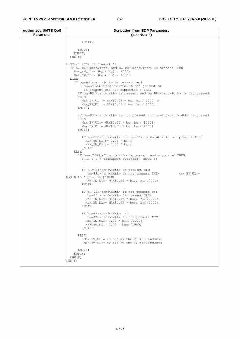
ETSI
ETSI TS 129 213 V14.5.0 (2017-10)1323GPP TS 29.213 version 14.5.0 Release 14
Authorized UMTS QoS Parameter
Derivation from SDP Parameters (see Note 4)
ENDIF; ENDIF; ENDIF; ENDIF; ELSE /* RTCP IP flow(s) */ IF bRS=RS:<bandwidth> and bRR=RR:<bandwidth> is present THEN Max_BW_UL:= (bRS + bRR) / 1000; Max_BW_DL:= (bRS + bRR) / 1000; ELSE IF bAS=AS:<bandwidth> is present and ( bTIAS=TIAS:<Tibandwidth> is not present or is present but not supported ) THEN IF bRS=RS:<bandwidth> is present and bRR=RR:<bandwidth> is not present THEN Max_BW_UL := MAX[0.05 * bAS, bRS / 1000] ; Max_BW_DL := MAX[0.05 * bAS, bRS / 1000] ; ENDIF; IF bRS=RS:<bandwidth> is not present and bRR=RR:<bandwidth> is present THEN Max_BW_UL:= MAX[0.05 * bAS, bRR / 1000]; Max_BW_DL:= MAX[0.05 * bAS, bRR / 1000]; ENDIF; IF bRS=RS:<bandwidth> and bRR=RR:<bandwidth> is not present THEN Max_BW_UL := 0.05 * bAS ; Max_BW_DL := 0.05 * bAS ; ENDIF; ELSE IF bTIAS=TIAS:<Tibandwidth> is present and supported THEN bTDBW= bTIAS + transport-overhead; (NOTE 6) IF bRS=RS:<bandwidth> is present and bRR=RR:<bandwidth> is not present THEN Max_BW_UL:= MAX[0.05 * bTDBW, bRS]/1000; Max_BW_DL:= MAX[0.05 * bTDBW, bRS]/1000; ENDIF; IF bRS=RS:<bandwidth> is not present and bRR=RR:<bandwidth> is present THEN Max_BW_UL:= MAX[0.05 * bTDBW, bRR]/1000; Max_BW_DL:= MAX[0.05 * bTDBW, bRR]/1000; ENDIF; IF bRS=RS:<bandwidth> and bRR=RR:<bandwidth> is not present THEN Max_BW_UL:= 0.05 * bTDBW /1000; Max_BW_DL:= 0.05 * bTDBW /1000; ENDIF; ELSE Max_BW_UL:= as set by the UE manufacture; Max_BW_DL:= as set by the UE manufacture; ENDIF; ENDIF; ENDIF; ENDIF;

ETSI
ETSI TS 129 213 V14.5.0 (2017-10)1333GPP TS 29.213 version 14.5.0 Release 14
Authorized UMTS QoS Parameter
Derivation from SDP Parameters (see Note 4)
Maximum Authorized Traffic Class [MaxTrafficClass] (see NOTE 1, 2 and3)
IF (all media IP flows of media type “audio” or “video” for the session are unidirectional and have the same direction) THEN MaxService:= streaming; ELSE MaxService:= conversational; ENDIF; CASE <media> OF “audio”: MaxTrafficClass:= MaxService; “video”: MaxTrafficClass:= MaxService; “application”: MaxTrafficClass:=conversational; “data”: MaxTrafficClass:=interactive with priority 3; “control”: MaxTrafficClass:=interactive with priority 1; /*new media type*/ OTHERWISE: MaxTrafficClass:=background; END;
NOTE 1: The Maximum Authorized Traffic Class for a RTCP IP flow is the same as for the corresponding RTP media IP flow.
NOTE 2: When audio or video IP flow(s) are removed from a session, the parameter MaxService shall keep the originally assigned value.
NOTE 3: When audio or video IP flow(s) are added to a session, the UE shall derive the parameter MaxService taking into account the already existing media IP flows within the session.
NOTE 4: The SDP parameters are described in RFC 2327 [11]. NOTE 5: The ‘b=RS:’ and ‘b=RR:’ SDP bandwidth modifiers are defined in RFC 3556 [13]. NOTE 6: TIAS is defined in IETF RFC 3890 [23]. RFC 3890 clause 6.4 provides procedures for converting TIAS to
transport-dependant values. This procedure relies on the presence of maxprate (also defined in RFC 3890).
The UE should per ongoing session store the Authorized UMTS QoS parameters per IP flow or bidirectional combination of IP flows.
Before activating or modifying a PDP context the UE should check that the requested Guaranteed Bitrate UL/DL (if the Traffic Class is Conversational or Streaming) or the requested Maximum Bitrate UL/DL (if the Traffic Class is Interactive or Background) does not exceed the Maximum Authorized Bandwidth UL/DL per PDP context (calculated according to the rule in table 6.5.2.2). If the requested Guaranteed Bitrate UL/DL or the requested Maximum Bitrate UL/DL exceeds the Maximum Authorized Bandwidth UL/DL per PDP context, the UE should reduce the requested Guaranteed Bitrate UL/DL or the requested Maximum Bitrate UL/DL to the Maximum Authorized Bandwidth UL/DL per PDP context. Furthermore, if the rule in table 6.5.2.1 for calculating Traffic Class per IP flow or bdirectional combination of IP flows is implemented, the UE should check that the requested UMTS QoS parameter Traffic Class does not exceed the Maximum Authorized Traffic Class per PDP context (calculated according to the rule in table 6.5.2.2). If the requested UMTS QoS parameter Traffic Class exceeds the Maximum Authorized Traffic Class per PDP context, the UE should reduce the requested UMTS QoS parameter Traffic Class to the Maximum Authorized Traffic Class per PDP context.
Table 6.5.2.2: Rules for calculating the Maximum Authorized Bandwidths and Maximum Authorized Traffic Class per PDP Context in the UE
Authorized UMTS QoS Parameter
per PDP Context
Calculation Rule
Maximum Authorized Bandwidth DL and UL per PDP Context
Maximum Authorized Bandwidth DL/UL per PDP Context is the sum of all Maximum Authorized Bandwidth DL/UL for all the IP flows or bidirectional combinations of IP flows (as derived according to table 6.5.2.1) associated with that PDP Context ; IF Maximum Authorized Bandwidth DL/UL per PDP Context > 256 Mbps THEN Maximum Authorized Bandwidth DL/UL per PDP Context = 256 Mbps /* See 3GPP TS 23.107 [4] */ END;
Maximum Authorized Traffic Class per PDP Context
Maximum Authorised Traffic Class per PDP Context = MAX [Maximum Authorized QoS Class per IP flow or bidirectional combination of IP flows (as derived according to table 6.5.2.1) among all the IP flows or bidirectional combinations of IP flows associated with that PDP Context] ; (The MAX function ranks the possible Maximum Authorised Traffic Class values as follows: Conversational > Streaming > Interactive with priority 1 > Interactive with priority 2 > Interactive with priority 3 > Background)
ETSI
ETSI TS 129 213 V14.5.0 (2017-10)1343GPP TS 29.213 version 14.5.0 Release 14
7 PCRF addressing
7.1 General The PCRF discovery procedures are needed where more than one PCRF is present in an operator’s network realm. Within such a deployment, an additional functional element, called DRA, is needed. PCRF discovery procedures include all the procedures that involve a DRA functional element.
Routing of Diameter messages from a network element towards the right Diameter realm in a PLMN is based on standard Diameter realm-based routing, as specified in IETF RFC 6733 [61] using the UE-NAI domain part. If PLMN is separated into multiple realms based on PDN information or IP address range (if applicable); the PDN information available in the Called-Station-Id AVP, or the UE’s Ipv4 address available in the Framed-IP-Address AVP or the UE’s Ipv6 address or prefix provided within the Framed-Ipv6-Prefix AVP may be used to assist routing PCC message to the appropriate Diameter realm.
The DRA keeps status of the assigned PCRF for a certain UE and IP-CAN session across all reference points, e.g. Gx, Gxx, S9, Rx and for unsolicited application reporting, the Sd interfaces.
The DRA shall support the functionality of a proxy agent and a redirect agent as defined in IETF RFC 6733 [61]. The mode in which it operates (i.e. proxy or redirect) shall be based on operator’s requirements.
Diameter clients of the DRA, i.e. AF, PCEF, BBERF, RCAF and PCRF in roaming scenarios shall support all procedures required to properly interoperate with the DRA in both the proxy and redirect modes.
NOTE: The proxy mode includes two variants:
PA1: Proxy agent based on the standard Diameter proxy agent functionality. All the messages need to go through the DRA.
PA2: Proxy agent based on the standard Diameter proxy agent functionality. Session establishment messages always go through the DRA. Gx, Gxx and S9 session termination messages always go through the DRA. All other messages bypass the DRA.
7.2 DRA Definition The DRA (Diameter Routing Agent) is a functional element that ensures that all Diameter sessions established over the Gx, S9, Gxx, Rx interfaces and for unsolicited application reporting, the Sd interface for a certain IP-CAN session reach the same PCRF when multiple and separately addressable PCRFs have been deployed in a Diameter realm. The DRA also ensures that the NRR commands over Np interface reach the same PCRF for a certain IP-CAN session. The DRA is not required in a network that deploys a single PCRF per Diameter realm.
7.3 DRA Procedures
7.3.1 General
A DRA implemented as a Diameter Redirect Agent or a Diameter Proxy Agent shall be compliant to IETF RFC 6733 [61], except when noted otherwise in this document.
7.3.2 DRA Information Storage
The DRA shall maintain PCRF routing information per IP-CAN session or per UE-NAI, depending on the operator’s configuration.
The DRA shall select the same PCRF for all the Diameter sessions established for the same UE in case 2a.
As there’s only one S9 session per UE, the V-DRA/H-DRA shall select the same V-PCRF/H-PCRF respectively for the same UE in the roaming case.

ETSI
ETSI TS 129 213 V14.5.0 (2017-10)1353GPP TS 29.213 version 14.5.0 Release 14
The DRA has information about the user identity (UE NAI), the UE Ipv4 address and/or Ipv6 prefix, the APN (if available), the PCEF identity (if available) and the selected PCRF identity for a certain IP-CAN Session.
NOTE 1: The DRA derives the PCEF identity from the Origin-Host AVP of the CCR command received from the PCEF.
The DRA finds the correct PCRF by matching the user identity (if available), IPv4 address or IPv6 address/prefix (if available) and APN (if available) received in the message from the BBERF/PCEF/AF/TDF/ RCAF/V-PCRF with the corresponding information stored the DRA.
NOTE 2: If the DRA does not use the IP address to find the PCRF and the user identity in the IP-CAN and the application level identity for the user are of different kinds (e.g. user identity is the IP-CAN is IMSI and application level identity for the user is SIPURI), the DRA needs to maintain, or have access to, the mapping between the identities. Such mapping is not subject to specification within this TS.
NOTE 3: An IPv6 address provided over Rx matches an IPv6 prefix stored in the DRA binding if the IPv6 address belongs to the IPv6 (sub-)network prefix.
When matching the APNs to each other, the DRA shall apply the procedures in Annex I.
For the PCRF selection over the Rx reference point, the DRA may additionally match the IP domain Id received in the message from the AF with the PCEF identity stored in the DRA to find the correct PCRF.
NOTE 4: In order to correlate the PCEF Identity and the domain identity, the DRA uses configured mapping between those identities.
For the PCRF selection over the Rx reference point, when the APN related to the IP-CAN session is dedicated for the purpose of offering services to remote UEs via a ProSe UE-to-network relay UE, the DRA shall use the UE IPv6 prefix alone to find the correct PCRF.
The PCRF routing information stored for an IP-CAN session in the DRA shall be removed after the IP-CAN session is terminated. In case of DRA change (e.g. inter-operator handover), the information about the IP-CAN session stored in the old DRA shall be removed.
The PCRF routing information stored per UE in the DRA may be removed when no more IP-CAN and gateway control sessions are active for the UE.
7.3.3 Capabilities Exchange
In addition to the capabilities exchange procedures defined in IETF RFC 6733 [61], the Redirect DRA and Proxy DRA shall advertise the specific applications it supports (e.g., Gx, Gxx, Rx, Np,S9 and for unsolicited application reporting, Sd) by including the value of the application identifier in the Auth-Application-Id AVP and the value of the 3GPP (10415) in the Vendor-Id AVP of the Vendor-Specific-Application-Id AVP contained in the Capabilities-Exchange-Request and Capabilities-Exchange-Answer commands.
7.3.4 Redirect DRA
7.3.4.1 Redirecting Diameter Requests
A DRA implemented as a Diameter redirect agent shall redirect the received Diameter request message by carrying out the procedures defined in clause 6.1.7 of IETF RFC 6733 [61]. The Client shall use the value within the Redirect-Host AVP of the redirect response in order to obtain the PCRF identity. The DRA may provide the Redirect-Host-Usage AVP in the redirect response to provide a hint to the Client about how the cached route table entry created from the Redirect-Host AVP is to be used as described in clause 6.13 of IETF RFC 6733 [61].
The two most revelant redirect host usage scenarios for PCC from IETF RFC 6733 [61]are:
- If the PCRF routing information is per UE-NAI, the DRA shall set the Redirect-Host-Usage AVP to ALL_USER. The DRA client may contact the DRA on IP-CAN session termination.
- If the PCRF routing information is per IP-CAN session, the DRA shall set the Redirect-Host-Usage AVP to ALL_SESSION. The DRA client shall contact the DRA on IP-CAN session termination.

ETSI
ETSI TS 129 213 V14.5.0 (2017-10)1363GPP TS 29.213 version 14.5.0 Release 14
The DRA may also provide the Redirect-Max-Cache-Time AVP in the redirect response to indicate to the Client the lifetime of the cached route table entry created from the Redirect-Host and Redirect-Host-Usage AVP values as described in clause 6.14 of IETF RFC 6733 [61].
If the DRA is maintaining PCRF routing information per IP-CAN session, the DRA shall be aware of Gx and Gxx Diameter termination requests as defined in 3GPP TS 29.212 [9] in order to detect whether release of DRA bindings is required. Otherwise the DRA clients shall use cached route table entry created from the Redirect-Host, Redirect-Host-Usage and Redirect-Max-Cache-Time AVPs to determine whether DRA interaction is required.
The DRA shall be aware of IP-CAN Session modification requests over Gx which is to update the Ipv4 address of the UE by the PCEF.
If the client is the AF, the DRA (redirect) does not need to maintain Diameter sessions and Diameter Base redirect procedures are applicable. Therefore, an AF should not send an AF session termination request to the DRA.
7.3.4.2 DRA binding removal
If the DRA binding is per IP-CAN session and the IP-CAN session is terminated or if the DRA binding is per UE and the last IP-CAN session is terminated (eg. From an indication by the BBERF/PCEF) the Redirect DRA shall remove the associated DRA binding information and responds with a Diameter redirect answer message.
7.3.5 Proxy DRA
The DRA shall support the functionality of a Diameter proxy agent as defined in IETF RFC 6733 [61].
When the DRA receives a request from a client, it shall check whether it already has selected a PCRF for the UE or the UE’s IP-CAN session; if it does have a PCRF already selected for that UE or UE’s IP-CAN session, it shall proxy the request to the corresponding PCRF. If the request is an IP-CAN session termination or gateway control session termination, the DRA shall check whether PCRF routing information shall be removed as specified in clause 7.3.3. If the DRA does not have a PCRF already selected, it shall follow one of the procedures below:
- If the request is an IP-CAN session establishment or gateway control session establishment, it shall select a PCRF to handle all sessions for that UE or UE’s IP-CAN session. It shall then proxy the request to the selected PCRF.
- Otherwise, if the request is not an IP-CAN session establishment or gateway control session establishment, it shall reject the request by returning a DIAMETER_UNABLE_TO_ COMPLY error code.
If a DRA is deployed in a PCRF’s realm, clients of the DRA shall send the first request of a session to the DRA handling the PCRF’s realm. Clients of the DRA shall as well send IP-CAN session termination and gateway control termination requests to the DRA. A client of the DRA shall be capable of sending every message of a session to the DRA. A client of the DRA may be configured to bypass the DRA on session modification messages and AF session termination messages by sending these types of messages directly to the PCRF.
7.3.6 PCRF selection by BBERF/PCEF (non-roaming case)
The PCEF (e.g. P-GW) or BBERF (e.g. Non-3GPP Access, S-GW) shall provide the DRA of the PCRF realm with identity parameters upon the first interaction between the access entity and the PCRF realm.
If the redirect agent is used for DRA, the DRA shall use the redirecting requests procedure as specified in IETF RFC 6733 [61], and include the PCRF identity in the Redirect-Host AVP in the Diameter reply sent to the PCEF or the BBERF.
If proxy agent is used for DRA, the DRA should use the proxy procedure as specified in IETF RFC 6733 [61]. For PA2 solution (described in clause 7.1), only session establishment, session modification with the UE’s Ipv4 address updated and session termination messages shall be sent through the DRA.
The identity parameters from the PCEF or BBERF may comprise the UE’s Ipv4 address in the Framed-IP-Address AVP and/or the UE’s Ipv6 prefix in the Framed-Ipv6-Prefix AVP, PDN information in the Called-Station-Id AVP and user identity in the Subscription-Id AVP.

ETSI
ETSI TS 129 213 V14.5.0 (2017-10)1373GPP TS 29.213 version 14.5.0 Release 14
7.3.7 PCRF selection by AF
If the AF has the realm identification (i.e. FQDN from a UE NAI) and is located in the HPLMN, the AF sends the user identity in the Subscription-Id AVP and PDN information (i.e. APN) if available in the Called-Station-Id AVP in a Diameter request to the DRA which acts as a Diameter agent.
For an AF serving mission critical communication services (e.g. MCPTT), the AF shall derive the realm of the PCRF based on the IP address and, based on the PLMN ID, construct the Diameter destination realm and use that destination realm in the initial request to address the DRA.
NOTE 1: An AF serving mission critical communication services as defined in 3GPP TS 23.280 [64] can be independent from a PLMN and is not guaranteed to have any realm identification.
If the AF does not have proper knowledge about the user identity and the AF is located in the HPLMN, the AF may use pre-configured information to find the DRA.
Editor’s Note: It is FFS how the AF (e.g. a third party or non-IMS application server) finds the DRA if it does not have the proper knowledge about the user identity. It is FFS whether a pre-configured destination realm will suffice in these cases.
The AF shall provide the DRA of the PCRF realm with identity parameters upon the first interaction between the AF and the PCRF realm.
If redirect agent is used for DRA, the DRA shall use the redirecting requests procedure as specified in IETF RFC 6733 [61], and include the PCRF identity in the Redirect-Host AVP in the Diameter reply sent to the AF.
If proxy agent is used for DRA, the DRA should use the proxy procedure as specified in IETF RFC 6733 [61]. For PA2 solution (described in clause 7.1), only AF session establishment messages shall be sent through the DRA.
The parameters from the AF may comprise the UE IP address in either the Framed-IP-Address AVP or the Framed-Ipv6-Prefix AVP, PDN information in the Called-Station-Id AVP, user identity in the Subscription-Id AVP and domain Identity in the IP-Domain-Id AVP (3GPP TS 23.203 [2]).
NOTE 2: In case the user identity in the IP-CAN and the application level identity for the user are of different kinds (e.g. user identity is the IP-CAN is IMSI and application level identity for the user is SIPURI), the DRA needs to maintain, or have access to, the mapping between the identities. Such mapping is not subject to specification within this TS.
7.3.8 PCRF selection in a roaming scenario
In the roaming case, a V-DRA is needed in the visited PLMN when there are more than one PCRFs per realm. The V-DRA will ensure that all the related Diameter sessions for a UE are handled by the same V-PCRF.
The BBERF in the visited access and home routed cases, the PCEF in the case of visited access and the AF when located in the visited PLMN may use pre-configured information (e.g. based on PDN) to find the V-DRA, and then find theV-PCRF. Other possible options are Dynamic peer discovery, or DNS-based.
The V-PCRF can find the H-DRA based on the UE NAI, and then find the H-PCRF by the H-DRA.
The V-PCRF shall provide the H-DRA of the H-PCRF realm with identity parameters upon the first interaction between the V-PCRF and the H-PCRF realm.
If redirect agent is used for H-DRA, the H-DRA shall use the redirecting requests procedure as specified in IETF RFC 6733 [61], and include the H-PCRF identity in the Redirect-Host AVP in the Diameter reply sent to the V-PCRF.
If proxy agent is used for H-DRA, the H-DRA should use the proxy procedure as specified in IETF RFC 6733 [61]. For PA2 solution (described in clause 7.1), only session establishment, session modification with the UE’s Ipv4 address updated and, only for the Gx, Gxx and S9 interfaces, termination messages shall be sent through the H-DRA.
The identity parameters from the V-PCRF may comprise the same parameters sent by the PCEF or the BBERF to the V-PCRF, i.e. the user identity (UE NAI), APN, the UE’s Ipv4 address and/or Ipv6 prefix (3GPP TS 23.203 [2]).

ETSI
ETSI TS 129 213 V14.5.0 (2017-10)1383GPP TS 29.213 version 14.5.0 Release 14
If redirect agent or PA2 is used for H-DRA, and the V-PCRF receives establishment message from the AF in the VPLMN, the V-PCRF may send the message to the H-PCRF directly (e.g. based on the stored information provided by H-DRA during the IP-CAN session establishment).
7.3.9 PCRF selection by TDF for unsolicited application reporting
The TDF uses pre-configured information to find the DRA.
The TDF shall provide the DRA of the PCRF realm with identity parameters upon the first interaction between the TDF and the PCRF realm.
If redirect agent is used for DRA, the DRA shall use the redirecting requests procedure as specified in IETF RFC 6733 [61], and include the PCRF identity in the Redirect-Host AVP in the Diameter reply sent to the TDF.
If proxy agent is used for DRA, the DRA should use the proxy procedure as specified in IETF RFC 6733 [61]. For PA2 solution (described in subclause 7.1), only TDF session establishment messages shall be sent through the DRA.
The parameters from the TDF may comprise the UE IP address in either the Framed-IP-Address AVP or the Framed-Ipv6-Prefix AVP and PDN information in the Called-Station-ID AVP.
NOTE: The TDF located in the HPLMN finds the H-PCRF for the roaming UE with home routed access case. The TDF located in the VPLMN finds the V-PCRF for the roaming UE with visited access case.
7.3.10 PCRF selection by RCAF
For initial Non-Aggregated RUCI reporting, the RCAF shall provide the identity parameters to the DRA of the PCRF realm.
The identity parameters from the RCAF may comprise PDN information in the Called-Station-Id AVP and user identity in the Subscription-Id AVP.
In the roaming with home-routed access case, the RCAF can find the H-DRA based on the IMSI, and then find the H-PCRF by the H-DRA.The RCAF shall provide the H-DRA of the H-PCRF realm with identity parameters upon the first interaction between the RCAF and the H-PCRF realm.
In the roaming with visited case, the RCAF shall provide the V-DRA of the V-PCRF realm with identity parameters upon the first interaction between the RCAF and the V-PCRF realm.
If the redirect agent is used for DRA, the DRA shall use the redirecting requests procedure as specified in IETF RFC 6733 [61], and include the PCRF identity in the Redirect-Host AVP in the Diameter reply sent to the RCAF.
If proxy agent is used for DRA, the DRA should use the proxy procedure as specified in IETF RFC 6733 [61].
For subsequent non-aggregated or aggregated RUCI reporting, the RCAF shall include the PCRF identity within the Destination-Host AVP for direct PCRF selection. The PCRF identity shall be responded by the PCRF within the PCRF-Address AVP in the initial non-aggregated RUCI reporting, for identifying the same destination PCRF in the subsequent non-aggregated or aggregated RUCI reporting.
7.4 DRA flows
7.4.1 Proxy DRA
7.4.1.1 Establishment of Diameter Sessions
7.4.1.1.1 Non-roaming cases
Establishment of Diameter sessions may occur at any of the following cases:
- Gateway control establishment
- IP-CAN session establishment

ETSI
ETSI TS 129 213 V14.5.0 (2017-10)1393GPP TS 29.213 version 14.5.0 Release 14
- AF session establishment
- For unsolicited application reporting, TDF session establishment
PA
2
1. External trigger
Legend:
Mandatory
Conditional
PCRF-1 Client (AF/BBERF/PCEF/TDF)
2. Rx/Gx/Gxx/Sd Diameter Request
4. Proxy Rx/Gx/Gxx/Sd Diameter Request
3. DRA binding creation/retrieval
5. Rx/Gx/Gxx/Sd Diameter Answer
DRA (proxy)
PCRF-2
6. Proxy Rx/Gx/Gxx/Sd Diameter Answer
7. PCRF address storage
Figure 7.4.1.1.1.1: Establishment of Diameter sessions using DRA (proxy)
1. A Client receives an external trigger (e.g. IP-CAN session establishment request) that requires the establishment of a Diameter session with a PCRF.
2. A Diameter Request (e.g. a Diameter CCR sent by PGW to indicate establishment of an IP-CAN session as defined in clauses 4.5.1, 4a.5.1 of 3GPP TS 29.212 [9]) is sent by the Client and received by a DRA (proxy).
3. The DRA (proxy) stores the user information (e.g. UE-NAI) and checks whether an active DRA binding exists. If not, the DRA creates a dynamic DRA binding (assignment of a PCRF node per UE or per IP-CAN session).
NOTE 1: When the AF establishes an Rx session or TDF establishes a TDF session with the DRA, there is already a DRA binding active.
4. The DRA (proxy) proxies the Diameter Request to the target PCRF. The proxied Diameter Request maintains the same Session-Id AVP value.
5. PCRF-1 returns a Diameter Answer as defined in clauses 4.5, 4a.5 of 3GPP TS 29.212 [9] to the DRA (proxy).
6. DRA (proxy) proxies the Diameter Answer to the Client. The proxied Diameter Answer maintains the same Session-Id AVP value.
7. If PA2 option is implemented, the Client uses the Origin-Host AVP value providedin the Diameter Answer of step 6. This value is the identity of the target PCRF. The client populates the Destination-Host AVP with this address and sends any subsequent Diameter messages directly to this PCRF bypassing the DRA (proxy).
NOTE 2: Figure 7.4.1.1.1.1 is also applicable when the AF/BBERF/PCEF/TDF in the VPLMN contacts the V-DRA to locate the V-PCRF.
7.4.1.1.2 Roaming cases
Establishment of Diameter sessions may occur at any of the following cases:
- V-PCRF initiates S9 Diameter session to H-PCRF

ETSI
ETSI TS 129 213 V14.5.0 (2017-10)1403GPP TS 29.213 version 14.5.0 Release 14
- V-PCRF proxies Rx Diameter session to H-PCRF
1. External trigger
H-PCRF-1 V-PCRF
2. Rx/S9 Diameter Request
4. Proxy Rx/S9 Diameter Request
3. DRA binding creation/retrieval
5. Rx/S9 Diameter Answer
H-DRA (proxy)
H-PCRF-2
6. Proxy Rx/S9 Diameter Answer
7. PCRF address storage
PA2
Legend:
Mandatory
Conditional
Figure 7.4.1.1.2.1: Establishment of Diameter sessions using DRA (proxy) – Roaming case
1. V-PCRF receives a trigger to establish a Diameter session to H-PCRF (e.g. S9 session establishment request).
2. A Diameter Request involving either the Rx or S9 protocol is sent by the V-PCRF and received by a H-DRA (proxy) in the home PLMN.
3. The H-DRA (proxy) stores the user information (e.g. UE-NAI) and checks whether an active DRA binding exists. If not, the H-DRA creates a dynamic DRA binding (assignment of a PCRF node per UE or per IP-CAN session).
4. The H-DRA (proxy) proxies the Diameter Request to the target PCRF in the home PLMN. The proxied Diameter Request maintains the same Session-Id AVP value.
5. H-PCRF-1 returns a Diameter Answer to the H-DRA (proxy).
6. H-DRA (proxy) proxies the Diameter Answer to the V-PCRF. The proxied Diameter Answer maintains the same Session-Id AVP value.
7. If PA2 option is implemented, the V-PCRF uses the Origin-Host AVP value provided in the Diameter Answer of step 6. This value is the identity of the target H-PCRF. The V-PCRF populates the Destination-Host AVP with this address and sends any subsequent Diameter messages directly to this H-PCRF bypassing the H-DRA.
7.4.1.2 Modification of Diameter Sessions
7.4.1.2.1 Non-roaming cases
7.4.1.2.1.1 Client-initiated
Modification of Diameter sessions may occur in any of the following cases:
- Gateway control session modification
- IP-CAN session modification
- AF session modification
- For unsolicited application reporting, TDF session modification

ETSI
ETSI TS 129 213 V14.5.0 (2017-10)1413GPP TS 29.213 version 14.5.0 Release 14
If PA1 option is implemented, only steps 2, 3, 4, 5, 6 are carried out. If PA2 option is implemented, only steps 2a, 5a are carried out.
1. External trigger
Legend:
Mandatory
Conditional
PCRF-1 Client (AF/BBERF/PCEF/TDF)
2. Sub-sequent Rx/Gx/Gxx/Sd Diameter Request
4. Proxy Rx/Gx/Gxx/Sd Diameter Request
3. Verify DRA Binding
5. Rx/Gx/Gxx/Sd Diameter Answer
DRA (proxy)
PCRF-2
6. Proxy Rx/Gx/Gxx/Sd Diameter Answer
2a. Sub-sequent Rx/Gx/Gxx/Sd Diameter Request
5a. Rx/Gx/Gxx/Sd Diameter Answer
PA
2 P
A2
Figure 7.4.1.2.1.1.1: Modification of Diameter sessions through DRA (proxy)- AF/BBERF/PCEF/TDF interaction
1. A Client receives an external trigger (e.g. IP-CAN session modification) that requires a subsequent Diameter message to be sent to the PCRF.
2. A subsequent Diameter Request (e.g. a Diameter CCR sent by PGW to indicate modification of an IP-CAN session) as defined in clauses 4.5.1, 4a.5.1 of 3GPP TS 29.212 [9] or clause 4.4 of 3GPP TS 29.214 [10]) is sent by the Client and received by the DRA (proxy).
2a If PA2 option is implemented, based on Client configuration and operator policy, the Client communicates directly to the PCRF, bypassing the DRA (proxy), by using the PCRF identity obtained through the Origin-Host AVP (see step 7 in clause 5.2.5.7.1.1). The Client uses the same active Session-Id AVP value on the Diameter Request sent to the PCRF. In such a case steps 2, 3, 4, 5, 6 are not carried out.
3. After receiving a Diameter Request (Step 2), the DRA (proxy) verifies that there is an active DRA binding for the session identified in the request.
4. The DRA (proxy) proxies the Diameter Request to the target PCRF.
5. PCRF-1 returns a Diameter Answer as defined in clauses 4.5, 4a.5 of 3GPP TS 29.212 [9] or clause 4.4 of 3GPP TS 29.214 [10]) to the DRA (proxy).
5a Upon receiving a Diameter Request (Step 2a), PCRF-1 returns a Diameter Answer directly to the Client, bypassing the DRA (proxy).
6. DRA (proxy) proxies the Diameter Answer to the Client.
NOTE: Figure 7.4.1.2.1.1.1 is also applicable when the AF/BBERF/PCEF/TDF in the VPLMN modifies the Diameter session through the V-DRA.
7.4.1.2.1.2 PCRF-initiated
Modification of Diameter sessions occur on PCRF initiated session modifications towards the clients (AF/BBERF/PCEF). If PA1 option is implemented, only steps 2, 3, 4, 5, 6 are carried out. If PA2 option is implemented, only steps 2a, 5a are carried out.

ETSI
ETSI TS 129 213 V14.5.0 (2017-10)1423GPP TS 29.213 version 14.5.0 Release 14
Legend:
Mandatory
Conditional
PCRF-1 Client (AF/BBERF/PCEF)
2. PCRF initiated Rx/Gx/Gxx Diameter Request
4. Proxy Rx/Gx/Gxx Diameter Request
3. Verify DRA Binding
5. Rx/Gx/Gxx Diameter Answer
DRA (proxy)
PCRF-2
6. Proxy Rx/Gx/Gxx Diameter Answer
2a. PCRF initiated Rx/Gx/Gxx Diameter Request
5a. Rx/Gx/Gxx Diameter Answer
PA
2 P
A2
1. Trigger
Figure 7.4.1.2.1.2.1: Modification of Diameter sessions through DRA (proxy)- PCRF interaction
1. PCRF receives an internal or external trigger that requires a Diameter message to be sent to the clients (either AF, BBERF, PCEF)
2. A PCRF-initiated Diameter Request (e.g. a Diameter RAR request sent to the PGW) is sent to the Clients and received by the DRA (proxy).
2a If PA2 option is implemented, the PCRF communicates directly to the client, bypassing the DRA (proxy). In such a case steps 2, 3, 4, 5, 6 are not carried out.
3. After receiving a Diameter Request (Step 2), the DRA (proxy) verifies that there is an active DRA binding for the session identified in the request.
4. The DRA (proxy) proxies the Diameter Request to the Client. The proxied Diameter Request maintains the same Session-Id AVP value.
5. Clients returns a Diameter Answer as defined in clauses 4.5, 4a.5 of 3GPP TS 29.212 [9] or clause 4.4 of 3GPP TS 29.214 [10]) to the DRA (proxy).
5a Upon receiving a Diameter Request (Step 2a), Client returns a Diameter Answer directly to the PCRF, bypassing the DRA (proxy).
6. DRA (proxy) proxies the Diameter Answer to the PCRF.
NOTE: Figure 7.4.1.2.1.2.1 is also applicable when the V-PCRF modifies the Diameter session through the V-DRA.
7.4.1.2.2 Roaming cases
7.4.1.2.2.1 V-PCRF initiated
In roaming scenarios modification of Diameter sessions may occur at any of the following cases:
�- V-PCRF S9 Diameter session modification to H-PCRF
- V-PCRF proxies Rx Diameter session modification to H-PCRF
If PA1 option is implemented, only steps 2, 3, 4, 5, 6 are carried out. If PA2 option is implemented, only steps 2a, 5a are carried out.

ETSI
ETSI TS 129 213 V14.5.0 (2017-10)1433GPP TS 29.213 version 14.5.0 Release 14
Legend:
Mandatory
Conditional
H-PCRF-1 V-PCRF
2. Rx/S9 Diameter session update
4. Proxy Rx/S9 Diameter session update
3. Verify DRA Binding
5. Rx/S9 Diameter Answer
H-DRA (proxy)
H-PCRF-2
6. Proxy Rx/S9 Diameter Answer
2a. Rx/S9 Diameter session update
5a. Rx/S9 Diameter Answer
PA
2 P
A2
1. Trigger
Figure 7.4.1.2.2.1.1: Modification of Diameter sessions through DRA (proxy) on roaming scenarios – V-PCRF initiated
1. V-PCRF receives an internal or external trigger that requires a Diameter message to be sent to H-PCRF over the S9 reference point
2. V-PCRF sends a Diameter session update (e.g. an S9 session modification request) over the S9 reference point that is received by the DRA (proxy) in the home PLMN.
2a If PA2 option is implemented, the V-PCRF communicates directly to the H-PCRF, bypassing the H-DRA (proxy). In such a case steps 2, 3, 4, 5, 6 are not carried out.
3. After receiving a Diameter Request (Step 2), the H-DRA (proxy) verifies that there is an active DRA binding for the session identified in the request.
4. The H-DRA (proxy) proxies the Diameter Request to the H-PCRF. The proxied Diameter Request maintains the same Session-Id AVP value.
5. H-PCRF returns a Diameter Answer to the H-DRA (proxy) in the home PLMN.
5a Upon receiving a Diameter Request (Step 2a), Client returns a Diameter Answer directly to the PCRF, bypassing the H-DRA (proxy).
6. H-DRA (proxy) proxies the Diameter Answer to the PCRF.
7.4.1.2.2.2 H-PCRF initiated
In roaming scenarios modification of Diameter sessions may occur at any of the following cases:
- H-PCRF S9 Diameter session modification to V-PCRF
If PA1 option is implemented, only steps 2, 3, 4, 5, 6 are carried out. If PA2 option is implemented, only steps 2a, 5a are carried out.

ETSI
ETSI TS 129 213 V14.5.0 (2017-10)1443GPP TS 29.213 version 14.5.0 Release 14
Legend:
Mandatory
Conditional
H-PCRF-1 V-PCRF
2. S9 Diameter Request
4. Proxy S9 Diameter Request
3. Verify DRA Binding
5. S9Diameter Answer
H-DRA (proxy)
H-PCRF-2
6. Proxy S9 Diameter Answer
2a. S9 Diameter Request
5a. S9 Diameter Answer
PA
2 P
A2
1. Trigger
Figure 7.4.1.2.2.2.1: Modification of Diameter sessions through DRA (proxy) on roaming scenarios – H-PCRF initiated
1. H-PCRF receives an internal or external trigger that requires a Diameter message to be sent to V-PCRF over the S9 reference point.
2. H-PCRF sends a Diameter session update (e.g. an S9 session modification request) over the S9 reference point that is received by the H-DRA (proxy) in the home PLMN.
2a If PA2 option is implemented, the H-PCRF communicates directly to the V-PCRF, bypassing the H-DRA (proxy). In such a case steps 2, 3, 4, 5, 6 are not carried out.
3. After receiving a Diameter Request (Step 2), the H-DRA (proxy) verifies that there is an active DRA binding for the session identified in the request.
4. The H-DRA (proxy) proxies the Diameter Request to the V-PCRF. The proxied Diameter Request maintains the same Session-Id AVP value.
5. V-PCRF returns a Diameter Answer to the H-DRA (proxy) in the home PLMN.
5a Upon receiving a Diameter Request (Step 2a), V-PCRF returns a Diameter Answer directly to the H-PCRF, bypassing the H-DRA (proxy).
6. H-DRA (proxy) proxies the Diameter Answer to the H-PCRF.
7.4.1.3 Termination of Diameter Sessions
7.4.1.3.1 Non-roaming cases
The procedures required are identical for both PA1 and PA2 options
Termination of Diameter sessions occur at the following cases:
- Gateway control session termination
- IP-CAN session termination
- AF session termination
- For unsolicited application reporting, TDF session termination

ETSI
ETSI TS 129 213 V14.5.0 (2017-10)1453GPP TS 29.213 version 14.5.0 Release 14
1. External trigger
Legend:
Mandatory
Conditional
PCRF-1 Client (AF/BBERF/PCEF/TDF)
2. Rx/Gx/Gxx/Sd Diameter Termination Request
4. Proxy Rx/Gx/Gxx/Sd Diameter Termination Request
3. Verify DRA binding
5. Rx/Gx/Gxx/Sd Diameter Answer
DRA (proxy)
PCRF-2
7. Proxy Rx/Gx/Gxx/Sd Diameter Answer
6. Remove DRA binding
Figure 7.4.1.3.1.1: Termination of Diameter sessions through DRA (proxy)
1. A Client receives an external trigger (e.g. an IP-CAN session termination is initiated by the UE or PCRF) that requires the sending of a Diameter Termination Request.
2. A Diameter Termination Request (e.g., a Diameter CCR sent by PGW to indicate termination of an IP-CAN session) as defined in clauses 4.5, 4a.5 of 3GPP TS 29.212 [9]) is sent by the Client to the DRA (proxy). The message uses the same Session-Id AVP value of the active Diameter session established between the Client and PCRF-1.
3. The DRA (proxy) verifies that there is an active DRA binding for the IP-CAN session based on the Session-Id AVP in the request.
4. The DRA (proxy) proxies the Diameter Termination Request to the target PCRF. The proxied Diameter Request maintains the same Session-Id AVP value.
5. PCRF-1 acknowledges termination of the session. PCRF-1 sends a Diameter Answer, (e.g., as defined in clauses 4.5, 4a.5 of 3GPP TS 29.212 [9]) to DRA (proxy).
6. The DRA marks the Diameter session terminated. If the DRA binding is per IP-CAN session and all the Diameter sessions (i.e. the Gx session or the Gxx session) of the IP-CAN session are terminated or if the DRA binding is per UE and all the Diameter sessions (i.e. the Gx session or the Gxx session) of that UE are terminated the DRA (proxy) removes the DRA binding.
7. DRA (proxy) proxies the Diameter Answer to the Client. The proxied Diameter Answer maintains the same Session-Id AVP value.
NOTE 1: Figure 7.4.1.3.1.1 is also applicable when the AF/BBERF/PCEF/TDF in the VPLMN terminates the Diameter sessions through the V-DRA.
NOTE 2: AF/TDF is not required to send Diameter session termination request to DRA (PA2).
7.4.1.3.2 Roaming cases
In roaming cases (over S9 reference point) termination of Diameter sessions occur at the following cases:
- S9 session termination
- AF session termination
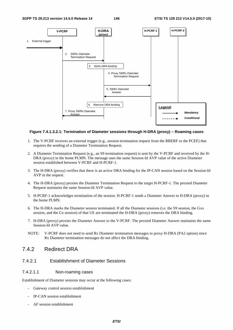
ETSI
ETSI TS 129 213 V14.5.0 (2017-10)1463GPP TS 29.213 version 14.5.0 Release 14
1. External trigger
Legend:
Mandatory
Conditional
H-PCRF-1 V-PCRF
2. S9/Rx Diameter Termination Request
4. Proxy S9/Rx Diameter Termination Request
3. Verify DRA binding
5. S9/Rx Diameter Answer
H-DRA (proxy)
H-PCRF-2
7. Proxy S9/Rx Diameter Answer
6. Remove DRA binding
Figure 7.4.1.3.2.1: Termination of Diameter sessions through H-DRA (proxy) – Roaming cases
1. The V-PCRF receives an external trigger (e.g., session termination request from the BBERF or the PCEF) that requires the sending of a Diameter Termination Request.
2. A Diameter Termination Request (e.g., an S9 termination request) is sent by the V-PCRF and received by the H-DRA (proxy) in the home PLMN. The message uses the same Session-Id AVP value of the active Diameter session established between V-PCRF and H-PCRF-1.
3. The H-DRA (proxy) verifies that there is an active DRA binding for the IP-CAN session based on the Session-Id AVP in the request.
4. The H-DRA (proxy) proxies the Diameter Termination Request to the target H-PCRF-1. The proxied Diameter Request maintains the same Session-Id AVP value.
5. H-PCRF-1 acknowledges termination of the session. H-PCRF-1 sends a Diameter Answer to H-DRA (proxy) in the home PLMN.
6. The H-DRA marks the Diameter session terminated. If all the Diameter sessions (i.e. the S9 session, the Gxx session, and the Gx session) of that UE are terminated the H-DRA (proxy) removes the DRA binding.
7. H-DRA (proxy) proxies the Diameter Answer to the V-PCRF. The proxied Diameter Answer maintains the same Session-Id AVP value.
NOTE: V-PCRF does not need to send Rx Diameter termination messages to proxy H-DRA (PA2 option) since Rx Diameter termination messages do not affect the DRA binding.
7.4.2 Redirect DRA
7.4.2.1 Establishment of Diameter Sessions
7.4.2.1.1 Non-roaming cases
Establishment of Diameter sessions may occur at the following cases:
- Gateway control session establishment
- IP-CAN session establishment
- AF session establishment

ETSI
ETSI TS 129 213 V14.5.0 (2017-10)1473GPP TS 29.213 version 14.5.0 Release 14
- For unsolicited application reporting, TDF session establishment
The DRA client (AF/BBERF/PCEF/TDF) shall follow the procedure below if an appropriate cached route table entry created from previous DRA (redirect) interactions does not exist. Cached route table entries are created from the Redirect-Host, Redirect-Host-Usage and Redirect-Max-Cache-Time AVPs as described in sections 6.12, 6.13 and 6.14 of IETF RFC 6733 [61].
1. External trigger
Legend:
Mandatory
Conditional
PCRF-1 Client (AF/BBERF/PCEF/TDF)
2. Rx/Gx/Gxx/Sd Diameter Establishment Request
4. Diameter Answer (redirect)
3. DRA binding creation/retrieval
6. Rx/Gx/Gxx/Sd Diameter Answer
DRA (redirect)
PCRF-2
5. Rx/Gx/Gxx/Sd DiameterEstablishment Request
Figure 7.4.2.1.1.1: Establishment of Diameter session through DRA (redirect)
1. A Client receives an external trigger (e.g., IP-CAN session establishment request) that requires the establishment of a Diameter session with a PCRF.
2. A Diameter Establishment request (e.g., a Diameter CCR sent by PGW to indicate establishment of an IP-CAN session as defined in clauses 4.5.1, 4a.5.1 of 3GPP TS 29.212 [9]) with user information (e.g., UE-NAI) is sent by the Client and received by the DRA (redirect).
3. The DRA (redirect) stores the user information (e.g., UE-NAI) and checks whether an active DRA binding exists. If not the DRA creates a dynamic DRA binding (assignment of a PCRF node per UE or per IP-CAN session); if the DRA (redirect) find there has been a DRA binding for the user, the DRA shall select the PCRF from the binding for the client.
4. The DRA (redirect) sends a Diameter Answer indicating redirection as defined in IETF RFC 6733 [61]. The target PCRF identity is included in the Redirect-Host AVP.
5. The Client re-sends the Diameter Establishment Request of step 2 to the target PCRF.
6. PCRF-1 returns a Diameter Answer, as defined in clauses 4.5, 4a.5 of 3GPP TS 29.212 [9], to the Client.
NOTE: Figure 7.4.2.1.1.1 is also applicable when the AF/BBERF/PCEF/TDF in the VPLMN contacts the V-DRA to locate the V-PCRF.
7.4.2.1.2 Roaming cases
Establishment of Diameter sessions may occur at the following cases:
- S9 session 147vailability147
- AF session establishment
The DRA client (AF/BBERF/PCEF) shall follow the procedure below if an appropriate cached route table entry created from previous DRA (redirect) interactions does not exist. Cached route table entries are created from the Redirect-Host,

ETSI
ETSI TS 129 213 V14.5.0 (2017-10)1483GPP TS 29.213 version 14.5.0 Release 14
Redirect-Host-Usage and Redirect-Max-Cache-Time AVPs as described in clause 6.12, 6.13 and 6.14 of IETF RFC 6733 [61].
1. External trigger
Legend:
Mandatory
Conditional
H-PCRF-1 V-PCRF
2. Rx/S9 Diameter Establishment Request
4. Diameter Answer (redirect)
3. DRA binding creation/retrieval
6. Rx/S9 Diameter Answer
H-DRA (redirect)
H-PCRF-2
5. Rx/S9 Diameter Establishment Request
Figure 7.4.2.1.2.1: Establishment of Diameter session through DRA (redirect) – Roaming scenario
1. The V-PCRF receives an external trigger (e.g., IP-CAN session establishment request) that requires the establishment of a Diameter session with an H-PCRF over the S9 reference point.
2. A Rx/S9 Diameter Establishment Request with user information (e.g., UE-NAI) is sent by the V-PCRF and received by the H-DRA (redirect) in the home PLMN.
3. The H-DRA (redirect) stores the user information (e.g., UE-NAI) and checks whether an active DRA binding exists. If not the H-DRA creates a dynamic DRA binding (assignment of a PCRF node per UE); if the DRA (redirect) find there has been a DRA binding for the user, the DRA shall select the PCRF from the binding for the client.
4. The H-DRA (redirect) sends a Diameter Answer indicating redirection as defined in IETF RFC 6733 [61]. The target PCRF identity is included in the Redirect-Host AVP.
5. The V-PCRF re-sends the Rx/S9 Diameter Establishment Request of step 2 to the target H-PCRF.
6. H-PCRF-1 returns a corresponding Diameter Answer to the V-PCRF.
NOTE: The V-PCRF may proxy the Rx Diameter Establishment Request to the H-PCRF directly (e.g. based on the stored information provided by H-DRA during the S9 Diameter session establishment).
7.4.2.2 Modification of Diameter sessions
The PCEF shall send the Diameter session modification message to the DRA to update the DRA binding information only if the UE’s address(es) is updated and the DRA (redirect) is maintaining PCRF routing information per IP-CAN session. For visited access case, the V-PCRF shall send the Diameter session modification message to the H-DRA to update the DRA binding information only if the UE’s address(es) is updated. The detailed procedure is similar to the Establishment of Diameter sessions, which is described in the clause 7.4.2.1.
7.4.2.3 Termination of Diameter Sessions
7.4.2.3.1 Non-roaming cases
Termination of Diameter sessions that impact the DRA binding occur at the following cases:

ETSI
ETSI TS 129 213 V14.5.0 (2017-10)1493GPP TS 29.213 version 14.5.0 Release 14
- Gateway control session termination
- IP-CAN session termination
The DRA client (BBERF/PCEF) shall follow the procedure below if the DRA (redirect) is maintaining PCRF routing information per IP-CAN session or an appropriate cached route table entry created from previous DRA (redirect) interactions does not exist. Cached route table entries are created from the Redirect-Host, Redirect-Host-Usage and Redirect-Max-Cache-Time AVPs as described in clause 6.12, 6.13 and 6.14 of IETF RFC 6733 [61].
1. External trigger
Legend:
Mandatory
Conditional
PCRF-1 Client (BBERF/PCEF)
2 Gx/Gxx Diameter Termination Request
6. Gx/Gxx Diameter Answer
4. DRA binding verification/release
5 Diameter Redirect Answer
DRA (redirect)
PCRF-2
3. Gx/Gxx Diameter Termination Request
Figure 7.4.2.3.1.1: Termination of Diameter sessions through DRA (redirect)
1. Client receives an external trigger (e.g. an IP-CAN session termination is initiated by the UE or PCRF) that triggers the client to terminate Diameter session with server (i.e. PCRF)
2 A Diameter Termination Request (e.g., as defined in clauses 4.5.7 (Gx) and 4a.5.3 (Gxx) of 3GPP TS 29.212 [9]) is sent by the Client to the DRA (redirect).
3. A Diameter Termination Request (e.g., as defined in clauses 4.5.7 (Gx) and 4a.5.3 (Gxx) of 3GPP TS 29.212 [9]) is sent by the Client to PRCF-1. The message uses the same Session-Id AVP value of the active Diameter session established between the Client and PCRF-1.
NOTE: Steps 2, 3 may be carried out in parallel. Otherwise, the client after step2 may need to wait for the redirect answer before sending the Diameter termination request to the PCRF.
4. DRA (redirect) verifies that there is an active DRA binding for the IP-CAN session based on the Session-Id AVP and marks the Diameter session terminated. If the DRA binding is per IP-CAN session and all the Diameter sessions (i.e. Gx session or Gxx session) of that IP-CAN session are terminated or if the DRA binding is per UE and all the Diameter sessions (i.e. Gx session or Gxx session) of that UE are terminated the DRA removes the DRA binding.
5 DRA (redirect) acknowledges termination of the session by sending a Diameter redirect answer to the client.
6 PCRF-1 acknowledges termination of session. PCRF-1 sends a Diameter Answer (e.g., as defined in clauses 4.5.7 (Gx) and 4a.5.3 (Gxx) of 3GPP TS 29.212 [9]) to the Client.
NOTE: Figure 7.4.2.3.1.1 is also applicable when the BBERF/PCEF in the VPLMN terminates the Diameter sessions through the V-DRA.
7.4.2.3.2 Roaming cases
Termination of Diameter sessions occur at the following cases:

ETSI
ETSI TS 129 213 V14.5.0 (2017-10)1503GPP TS 29.213 version 14.5.0 Release 14
- S9 session termination
The DRA client (AF/BBERF/PCEF) shall follow the procedure below) if the DRA (redirect) is maintaining PCRF routing information per IP-CAN session or an appropriate cached route table entry created from previous DRA (redirect) interactions does not exist. Cached route table entries are created from the Redirect-Host, Redirect-Host-Usage and Redirect-Max-Cache-Time AVPs as described in clause 6.12, 6.13 and 6.14 of IETF RFC 6733 [61].
1. External trigger
Legend:
Mandatory
Conditional
H-PCRF-1 V-PCRF
2 S9 Diameter Termination Request
6. S9 Diameter Answer
4. DRA binding verification/release
5 Diameter Redirect Answer
H-DRA (redirect)
H-PCRF-2
3. S9 Diameter Termination Request
Figure 7.4.2.3.2.1: Termination of Diameter sessions through DRA (redirect) – Roaming case
1. V-PCRF receives an external trigger (e.g. session termination request from the BBERF, PCEF) that requires the sending of a Diameter Termination Reqeust.
2 A Diameter Termination Request is sent by the V-PCRF and received by the H-DRA (redirect) in the home PLMN.
3. A Diameter Termination Request is sent by the V-PCRF to H-PRCF-1. The message uses the same Session-Id AVP value of the active Diameter session established between theV-PCRF and H-PCRF-1.
NOTE: Steps 2, 3 may be carried out in parallel. Otherwise, the V-PCRF after step2 may need to wait for the redirect answer before sending the Diameter termination request to the H-PCRF
4. H-DRA (redirect) verifies that there is an active DRA binding for the IP-CAN session based on the Session-Id AVP and marks the Diameter session terminated. If all the Diameter sessions (i.e. S9 session, Gxx session, Gx session) of that UE are terminated the H-DRA removes the DRA binding.
5 H-DRA (redirect) acknowledges termination of the session by sending a Diameter redirect answer to the V-PCRF.
6 H-PCRF-1 acknowledges termination of the session by sending a Diameter answer to the V-PCRF.
NOTE: Rx Diameter termination messages are not required to be sent to H-DRA (redirect) since such messages do not affect the DRA binding
ETSI
ETSI TS 129 213 V14.5.0 (2017-10)1513GPP TS 29.213 version 14.5.0 Release 14
8 Diameter race condition handling
8.1 Overview Certain Diameter PCC applications (Gx, Gxx, Sd, S9) allow the server (PCRF for Gx, Gxx, Sd, H-PCRF for S9) to update a session in two ways: unsolicited and solicited. The PCRF can push policy decisions and provision event triggers in an unsolicited fashion using an RAR. It can also install policy decisions in a solicited manner by responding to a CCR sent by the client (BBERF for Gxx, PCEF for Gx, TDF for Sd, V-PCRF for S9).
The client and the server can initiate transactions that modify the state of the session independently (e.g. CCR from the client and RAR from the server) and potentially concurrently. Additionally, there may be Diameter agents in between the client and server (e.g. DRA or in general Diameter relays/proxies) that could cause messages to be delivered out of order. This can lead to race conditions that may result in the wrong information maintained by the client and/or server for a session.
Note that race conditions occur in different ways based on the application. Also, their impact is specific to the application. For example, even though Gx is based on DCCA (RFC 4006), Gx is much more vulnerable to race conditions as Gx allows sessions to be updated based on RARs and CCAs whereas DCCA only allows the server to update the session based on a CCA. The RAR is merely used to solicit the client to send a CCR.
8.2 Procedures for Gx, Gxx, Sd and S9 This clause describes the optional procedures for handling Diameter race conditions in a deterministic manner for the following interfaces: Gx, Gxx, Sd and S9. These procedures apply to the PCEF (Gx), BBERF (Gxx), TDF (Sd) and PCRF (Gx, Gxx, Sd and S9).
In this clause, the terms “client” and “server” are relative to the session context. As an example, for the Gx interface, the client is the PCEF and the server is the PCRF. The term “node” can refer to either a client or a server. The term “transaction” refers to a Diameter request and its associated answer. The term “ongoing transaction” refers to a transaction that has an outstanding answer.
A node that supports the procedures defined in this clause and is configured to comply with them, shall advertise such support by setting the corresponding PendingTransaction feature bit in the Supported-Features AVP during session establishment as defined in 3GPP TS 29.212 [9] for Gx, Gxx and Sd and 3GPP TS 29.215 [22] for S9.
On receipt of a Diameter request for an existing Diameter session, the recipient Diameter node shall check if it has an ongoing transaction on that session:
1. If there are no ongoing transactions on the session, the node shall process the incoming request normally.
2. If there is an ongoing transaction on the session and optionally, if the recipient node cannot determine that the incoming request can be safely handled without creating a state mismatch:
a. The client shall reject the incoming request with a Diameter experimental result code of DIAMETER_PENDING_TRANSACTION as defined in 3GPP TS 29.212 [9].
b. The server shall either reject the incoming request with a Diameter experimental result code of DIAMETER_PENDING_TRANSACTION or shall wait for one of the following conditions to occur:
i. The ongoing transaction completes. In this case, the session is updated at the server based on the completion of the ongoing transaction and afterwards, the incoming request (e.g. CCR) is processed normally based on the updated session state.
ii. The waiting period has exceeded its allotted time. In this case, the server shall reject the incoming request with a Diameter experimental result code of DIAMETER_PENDING_TRANSACTION.
3. On receipt of a DIAMETER_PENDING_TRANSACTION result code, a client shall retry the request. On the other hand, if a server had rejected a request from the client with a DIAMETER_PENDING_TRANSACTION, the server should not retry the failed request until it receives the re-attempted request from the client. This is to avoid having both the client and server concurrently retry their requests. In all other cases, if the session on the client still needs to be updated, the server shall retry the request.

ETSI
ETSI TS 129 213 V14.5.0 (2017-10)1523GPP TS 29.213 version 14.5.0 Release 14
4. Nodes should limit the number of times they re-attempt the same request due to receipt of a DIAMETER_PENDING_TRANSACTION.
5. The only exception to the rules above is a session termination request (e.g. CCR with a CC-Request-Type AVP set to TERMINATION_REQUEST) or a request for session release (e.g. RAR with Session-Release-Cause AVP). In both cases, the request should be handled as follows:
a. When receiving a request for a session release that requires new transactions to be initiated, a client shall acknowledge the request immediately (e.g. a RAR command with Session-Release-Cause AVP shall be acknowledged with a RAA command). The client shall wait for the current transaction to complete (either by the server acknowledgeing the request or rejecting it with DIAMETER_PENDING_TRANSACTION) before completing the session termination procedure (e.g. before sending the CCR command with the CC-Request-Type set to TERMINATION_REQUEST).
NOTE: The client needs to wait for the outcome of the session modification to determine if the session termination procedure will be used to report information that could not be reported as part of the session modification procedure.
b. When receiving a session termination request the server shall handle it immediately.

ETSI
ETSI TS 129 213 V14.5.0 (2017-10)1533GPP TS 29.213 version 14.5.0 Release 14
Annex A (informative): Examples of deriving the Maximum Authorized parameters from the SDP parameters

ETSI
ETSI TS 129 213 V14.5.0 (2017-10)1543GPP TS 29.213 version 14.5.0 Release 14
Annex B (normative): Signalling Flows for IMS The signalling flows in clause 4 are also applicable for IMS. This Annex adds flows that show interactions with SIP/SDP signalling of the IMS.
B.0 General The following is applicable for Emergency Services and PSAP call back request:
- The P-CSCF includes an Emergency indication when service information is sent over Rx and when required by the IMS deployment, the P-CSCF may also indicate that it requires EPC-level user information as defined in 3GPP TS 29.214 [10].
- The PCRF only allows Emergency Sessions that are bound to an IP-CAN session established to an Emergency APN.
- Upon request from the P-CSCF, the PCRF provides the P-CSCF with EPC-level user information corresponding to the established IP-CAN session.
The following is not applicable for Emergency Services and PSAP call back request:
- Pre-authorization for a UE terminated IMS session establishment with UE initiated resource reservation.
- Subscription to notification of Signalling Path Status at IMS Registration, subscription to notification of changes of IP-CAN type at IMS Registration and Provisioning of SIP Signalling flow information at IMS Registration procedures.
B.1 Subscription to Notification of Signalling Path Status at IMS Registration
This clause covers the optional Subscription to Notifications of IMS Signalling Path Status upon an initial successful IMS Registration procedure.

ETSI
ETSI TS 129 213 V14.5.0 (2017-10)1553GPP TS 29.213 version 14.5.0 Release 14
7. Diameter AAA
5. Diameter AAR
P-CSCF
PCRF
1. SIP REGISTER
2. SIP REGISTER
3. 200 OK 4. 200 OK
UE
6. Session Binding
Legend:
Mandatory
Optional
8. Subscribe to Bearer Level Event
Figure B.1.1: Subscription to Notification of IMS Signaling Path Status at initial IMS Registration
1-4. The user initiates an initial SIP Registration procedure. The SIP Registration procedure is completed successfully (user has been authenticated and registered within the IMS Core NW).
5. The P-CSCF requests the establishment of a new Diameter Rx session with the intention to subscribe to the status of the IMS Signaling path. The P-CSCF sends a Diameter AAR command to the PCRF.
6. The PCRF performs session binding and identifies corresponding PCC Rules related to IMS Signalling.
7. The PCRF confirms the subscription to IMS Signaling path status and replies with a Diameter AAR command back to the P-CSCF.
8. If the PCRF had not previously subscribed to the required bearer level events from the IP-CAN for the affected PCC/QoS Rules, then the PCRF shall do so now. The PCRF initiates procedures according to figure 4.3.1.1.1.
B.1a Subscription to Notification of Change of IP-CAN Type at IMS Registration
This clause covers the optional Subscription to Notifications of change in the type of IP-CAN upon an initial IMS Registration procedure.

ETSI
ETSI TS 129 213 V14.5.0 (2017-10)1563GPP TS 29.213 version 14.5.0 Release 14
4. Diameter AAA
2. Diameter AAR
P-CSCF
PCRF
1. SIP REGISTER
5. SIP REGISTER
UE
3. Session Binding
Legend:
Mandatory
Optional
6. 200 OK 7. 200 OK
8. Subscribe to Bearer Level Event
Figure B.1.2: Subscription to Notification of change of IP-CAN Type at initial IMS Registration
1.- The user initiates an initial SIP Registration procedure.
2. The P-CSCF requests the establishment of a new Diameter Rx session with the intention to subscribe to the notification of IP-CAN Type Change. The P-CSCF sends a Diameter AAR command to the PCRF.
NOTE: It should be possible for the P-CSCF to request the subscription to notification of IMS Signalling path status and PLMN changes also in this step.
3. The PCRF performs session binding and identifies corresponding PCC Rules related to IMS Signalling.
4. The PCRF confirms the subscription to notification of change of IP-CAN type and replies with a Diameter AAA command back to the P-CSCF. The PCRF includes in the response the type of IP-CAN currently in use.
5-7. The SIP Registration procedure is completed successfully (user has been authenticated and registered within the IMS Core NW).
8. If the PCRF had not previously subscribed to the required bearer level event from the IP-CAN (i.e. IP-CAN type change and RAT type change, if applicable), then the PCRF shall do so now. The PCRF initiates procedures according to figure 4.3.1.1.1.
B.1b Provisioning of SIP signalling flow information at IMS Registration
This clause covers the optional Provisioning of SIP signalling flow information upon an initial successful IMS Registration procedure.

ETSI
ETSI TS 129 213 V14.5.0 (2017-10)1573GPP TS 29.213 version 14.5.0 Release 14
7. Diameter AAA
5. Diameter AAR
P-CSCF
PCRF
1. SIP REGISTER
2. SIP REGISTER
3. 200 OK4. 200 OK
UE
6. Session Binding
Legend:
Mandatory
Optional
8. Provisioning of PCC/QoS Rules
Figure B.1.3: Provisioning of SIP Signalling Flow Information at initial IMS Registration
1-4. The user initiates an initial SIP Registration procedure. The SIP Registration procedure is completed successfully (user has been authenticated and registered within the IMS Core NW).
5. The P-CSCF requests the establishment of a new Diameter Rx session with the intention to provision the information about the SIP signalling flows established between the UE and the P-CSCF. The P-CSCF sends a Diameter AAR command to the PCRF.
6. The PCRF performs session binding and identifies corresponding PCC Rules related to IMS Signalling.
7. The PCRF replies to the P-CSCF with a Diameter AAA.
8. If the PCRF had not previously provisioned PCC/QoS rules corresponding to the received SIP signalling flows, then the PCRF executes interactions according to figure 4.3.1.1.1. This step implies provisioning of PCC/QoS rules.
B.1c Subscription to Notification of Change of PLMN Identifier at IMS Registration
This clause covers the optional Subscription to Notifications of change in the PLMN identifier upon an initial IMS Registration procedure.

ETSI
ETSI TS 129 213 V14.5.0 (2017-10)1583GPP TS 29.213 version 14.5.0 Release 14
4. Diameter AAA
2. Diameter AAR
P-CSCF
PCRF
1. SIP REGISTER
5. SIP REGISTER
UE
3. Session Binding
Legend:
Mandatory
Optional
6. 200 OK 7. 200 OK
8. Subscribe to Bearer Level Event
Figure B.1.4: Subscription to Notification of change of PLMN Identifier at initial IMS Registration
1. The user initiates an initial SIP Registration procedure.
2. The P-CSCF requests the establishment of a new Diameter Rx session with the intention to subscribe to the notification of PLMN Identifier Change. The P-CSCF sends a Diameter AAR command to the PCRF.
NOTE 1: It should be possible for the P-CSCF to request the subscription to notification of IMS Signalling path status and IP-CAN Type changes also in this step.
3. The PCRF performs session binding and identifies corresponding PCC Rules related to IMS Signalling.
4. The PCRF confirms the subscription to notification of change of PLMN identifier and replies with a Diameter AAA command back to the P-CSCF. The PCRF includes in the response the PLMN Identifier currently in use, if available.
5-7. The SIP Registration procedure is completed successfully (user has been authenticated and registered within the IMS Core NW).
8. If the PCRF had not previously subscribed to the required bearer level event from the PLMN where the UE is located (i.e. PLMN change event), then the PCRF shall do so now. The PCRF initiates procedures according to figure 4.3.1.1.1.
NOTE 2: If the PLMN identifier is not available in step 4, the P-CSCF will wait to get it in step 8 before progressing the SIP Register, i.e. steps 5, 6 and 7 will occur after step 8.

ETSI
ETSI TS 129 213 V14.5.0 (2017-10)1593GPP TS 29.213 version 14.5.0 Release 14
B.2 IMS Session Establishment
B.2.1 Provisioning of service information at Originating P-CSCF and PCRF
This clause covers the PCC procedures at the originating P-CSCF and PCRF at IMS session establishment.
In figure B.2.1.1 the P-CSCF derives the provisioning of service information to the PCRF from the SDP offer/answer exchange.
Figure B.2.1.1: PCC Procedures for IMS Session Establishment at originating P-CSCF and PCRF
1. The P-CSCF receives the SDP parameters defined by the originator within an SDP offer in SIP signalling.
2. The P-CSCF identifies the connection information needed (IP address of the down link IP flow(s), port numbers to be used etc…).
3. The P-CSCF forwards the SDP offer in SIP signalling.
4. The P-CSCF gets the negotiated SDP parameters from the terminating side through SIP signalling interaction.

ETSI
ETSI TS 129 213 V14.5.0 (2017-10)1603GPP TS 29.213 version 14.5.0 Release 14
5. The P-CSCF identifies the connection information needed (IP address of the up-link media IP flow(s), port numbers to be used etc…).
6. The P-CSCF forwards the derived session information to the PCRF by sending a Diameter AAR over a new Rx Diameter session.
7. The PCRF stores the received session information, and performs session binding.
8. The PCRF replies to the P-CSCF with a Diameter AAA.
9. Upon reception of the acknowledgement from the PCRF, the SDP parameters are passed to the UE in SIP signalling.
10. The PCRF executes interactions according to figure 4.3.1.1.1 . This step implies provisioning of PCC/QoS rules and is executed in parallel with steps 8 and 9.
11. If the P-CSCF requested access network information in step 6, the PCRF forwards the access network information received in step 10 in a Diameter RAR.
12. If step 11 occurs, the P-CSCF acknowledges the receipt of Diameter RAR.
13. If step 11 occurs, the P-CSCF forwards the access network information as the network provided location information when a suitable SIP message is received.
Optionally, the provisioning of service information may be derived already from the SDP offer to enable that a possible rejection of the service information by the PCRF is obtained by the P-CSCF in time to reject the service with appropriate SIP signalling, to allow the P-CSCF to request network provided location information for inclusion in the SDP offer, to support authentication of roaming users in deployments with no IMS-level roaming interfaces or to support PSAP callback functionality for anonymous IMS emergency sessions. This is described in figure B.2.1.2.

ETSI
ETSI TS 129 213 V14.5.0 (2017-10)1613GPP TS 29.213 version 14.5.0 Release 14
Figure B.2.1.2: PCC Procedures for IMS Session Establishment at originating P-CSCF and PCRF, provisioning of service information derived from SDP offer and answer
1. The P-CSCF receives the first SDP offer for a new SIP dialogue within a SIP INVITE request.
2. The P-CSCF extracts service information from the SDP offer (IP address of the down link IP flow(s), port numbers to be used etc…).
3. The P-CSCF forwards the derived service information to the PCRF by sending a Diameter AAR over a new Rx Diameter session. It indicates that only an authorization check of the service information is requested.
4. The PCRF checks and authorizes the service information, performs session binding, but does not provision PCC/QoS rules at this stage.
5. The PCRF replies to the P-CSCF with a Diameter AAA.
6. If the P-CSCF did not request access network information in step 3, or if the P-CSCF requested access network information but does not require the access network information for inclusion in the SDP offer, or the P-CSCF requested EPC-level user information in step 3 the P-CSCF forwards the SDP offer in SIP signalling.

ETSI
ETSI TS 129 213 V14.5.0 (2017-10)1623GPP TS 29.213 version 14.5.0 Release 14
7. If the P-CSCF requested access network information in step 3, the PCRF executes interactions according to Figure 4.3.1.1.1. This step implies provisioning of PCC/QoS rules.
8. If the P-CSCF requested access network information in step 3, the PCRF forwards the access network information received in step 7 in a Diameter RAR.
9. If step 8 occurs, the P-CSCF acknowledges the receipt of Diameter RAR.
10a. If step 8 occurs, and if the P-CSCF requires the access network information for inclusion in the SDP offer, the P-CSCF forwards the SDP offer and adds the access network information as the network provided location information to the corresponding SIP message.
10b. If step 8 occurs, and if the P-CSCF does not require the access network information for inclusion in the SDP offer, the P-CSCF forwards the access network information as the network provided location information in a suitable SIP message. This step normally occurs only after step 17.
11. The P-CSCF receives the negotiated SDP parameters from the terminating side within a SDP answer in SIP signalling.
12. The P-CSCF extracts service information from the SDP answer (IP address of the up-link media IP flow(s), port numbers to be used etc…).
13. The P-CSCF forwards the derived service information to the PCRF by sending a Diameter AAR over the existing Rx Diameter session. Access network information is not requested if done in step 7.
14. The PCRF stores the received session information.
15. The PCRF replies to the P-CSCF with a Diameter AAA.
16. The PCRF authorizes the session information. The PCRF executes interactions according to Figure 4.3.1.1.1. This step implies provisioning of PCC/QoS rules and authorized QoS.
17. Upon successful authorization of the session, the SDP parameters are passed to the UE in SIP signalling. This step is executed in parallel with step 16.
B.2.2 Provisioning of service information at terminating P-CSCF and PCRF
This clause covers the PCC procedures at the terminating P-CSCF and PCRF at IMS session establishment.
In figure B.2.2.1 the P-CSCF derives the provisioning of service information to the PCRF from the SDP offer/answer exchange.

ETSI
ETSI TS 129 213 V14.5.0 (2017-10)1633GPP TS 29.213 version 14.5.0 Release 14
Figure B.2.2.1: PCC Procedures for IMS Session Establishment at terminating P-CSCF and PCRF
1. The P-CSCF receives the SDP parameters defined by the originator.
2. The P-CSCF identifies the connection information needed (IP address of the up-link IP flow(s), port numbers to be used etc…).
3. The P-CSCF sends the SDP offer to the UE.
4. The P-CSCF receives the negotiated SDP parameters from the UE.
5. The P-CSCF identifies the connection information needed (IP address of the down-link IP flow(s), port numbers to be used etc…).
6. The P-CSCF forwards the derived service information to the PCRF by sending a Diameter AAR over a new Rx Diameter session.
7. The PCRF stores the received session information, and performs session binding.
8. The PCRF sends a Diameter AAA to the P-CSCF.

ETSI
ETSI TS 129 213 V14.5.0 (2017-10)1643GPP TS 29.213 version 14.5.0 Release 14
9. If the P-CSCF did not request access network information in step 6, upon reception of the acknowledgement from the PCRF, the SDP parameters in the SDP answer are passed to the originator.
10. The PCRF executes interactions according to clause 4.3.1.1.1. This step implies provisioning of PCC/QoS rules and is executed in parallel with steps 8 and 9.
11. If the P-CSCF requested access network information in step 6, the PCRF forwards the access network information received in step 10 in a Diameter RAR.
12. If step 11 occurs, the P-CSCF acknowledges the receipt of Diameter RAR.
13. If step 11 occurs, the P-CSCF forwards the SDP answer and adds the access network information as the network provided location information to the corresponding SIP message.
Optionally, the provisioning of service information may be derived already from the SDP offer to enable that a possible rejection of the service information by the PCRF is obtained by the P-CSCF in time to reject the service with appropriate SIP signalling or to enable pre-authorization for a UE terminated IMS session establishment with UE initiated resource reservation. This is described in figure B.2.2.2.

ETSI
ETSI TS 129 213 V14.5.0 (2017-10)1653GPP TS 29.213 version 14.5.0 Release 14
Figure B.2.2.2: PCC Procedures for IMS Session Establishment at terminating P-CSCF and PCRF, provisioning of service information derived from SDP offer and answer
1. The P-CSCF receives the first SDP offer for a new SIP dialogue within SIP signalling, e.g. within a SIP INVITE request.
2. The P-CSCF extracts the service information from the SDP offer (IP address of the up-link IP flow(s), port numbers to be used etc…).

ETSI
ETSI TS 129 213 V14.5.0 (2017-10)1663GPP TS 29.213 version 14.5.0 Release 14
3. The P-CSCF forwards the derived session information to the PCRF by sending a Diameter AAR over a new Rx Diameter session. It indicates that the service information that the AF has provided to the PCRF is preliminary and needs to be further negotiated between the two ends.
4. The PCRF checks and authorizes the session information, performs session binding, but does not provision PCC/QoS Rules at this stage.
5. The PCRF replies to the P-CSCF with a Diameter AAA.
6. The P-CSCF sends the SDP offer to the UE.
7. If the UE initiates a bearer resource modification request, the PCRF provides the PCEF/BBERF with PCC/QoS rules according to figure 4.3.1.1.1 based on the SDP offer.
NOTE: Step 7 is not applicable for IMS Emergency Sessions.
8. The P-CSCF receives the negotiated SDP parameters from the UE within an SDP answer in SIP signalling.
9. The P-CSCF extracts service information from the SDP answer (IP address of the down-link IP flow(s), port numbers to be used etc…).
10. The P-CSCF forwards the derived service information to the PCRF by sending a Diameter AAR over the existing Rx Diameter session.
10a. The PCRF stores the received session information.
11. The PCRF sends a Diameter AAA to the P-CSCF.
12. The PCRF authorizes the session information. The PCRF executes interactions according to Figure 4.3.1.1.1. This step implies provisioning of PCC/QoS rules and authorized QoS.
13. If the P-CSCF did not request access network information in step 3 or 10, upon successful authorization of the session the SDP parameters in the SDP answer are passed to the originator. This step is executed in parallel with step 12.
14. If the P-CSCF requested access network information in step 3 or 10, the PCRF forwards the access network information received in step 12 in a Diameter RAR.
15. If step 14 occurs, the P-CSCF acknowledges the receipt of Diameter RAR.
16. If step 14 occurs, the P-CSCF forwards the SDP answer and adds the access network information as the network provided location information to the corresponding SIP message.
B.3 IMS Session Modification
B.3.1 Provisioning of service information This clause covers the provisioning of service information at IMS session modification both at the originating and terminating side.
In figure B.3.1.1 the P-CSCF derives the provisioning of service information to the PCRF from the SDP offer/answer exchange.

ETSI
ETSI TS 129 213 V14.5.0 (2017-10)1673GPP TS 29.213 version 14.5.0 Release 14
Figure B.3.1.1: Provisioning of service information at IMS session modification
1. The P-CSCF receives the SDP parameters defined by the originator within an SDP offer in SIP signalling.
2. The P-CSCF identifies the relevant changes in the SDP.
3. The P-CSCF forwards the SDP offer in SIP signalling.
4. The P-CSCF gets the negotiated SDP parameters from the terminating side through SIP signalling interaction.
5. The P-CSCF identifies the relevant changes in the SDP.
6. The P-CSCF sends a Diameter AAR for an existing Diameter session and includes the derived updated service information.
ETSI
ETSI TS 129 213 V14.5.0 (2017-10)1683GPP TS 29.213 version 14.5.0 Release 14
7. The PCRF stores the received updated session information and identifies the affected established IP-CAN Session(s).
8. The PCRF answers with a Diameter AAA.
9. If the P-CSCF did not request access network information in step 6, the P-CSCF forwards the SDP answer in SIP signalling.
10. The PCRF executes interactions according to figure 4.3.1.1.1. Due to the updated service information, this step may imply provisioning of PCC/QoS rules or the need to enable or disable IP Flows (see clauses B.3.2 and B.3.3, respectively).
11. If the P-CSCF requested access network information in step 6, the PCRF forwards the access network information received in step 10 in a Diameter RAR.
12. If step 11 occurs, the P-CSCF acknowledges the receipt of Diameter RAR.
13. If step 11 occurs, the P-CSCF forwards the SDP answer and adds the access network information as the network provided location information to the corresponding SIP message.
Optionally, the provisioning of service information may be derived already from the SDP offer to enable that a possible rejection of the service information by the PCRF is obtained by the P-CSCF in time to reject the service with appropriate SIP signalling or to enable pre-authorization for a UE terminated IMS session establishment with UE initiated resource reservation. This is described in figure B.3.1.2.

ETSI
ETSI TS 129 213 V14.5.0 (2017-10)1693GPP TS 29.213 version 14.5.0 Release 14
11 . Diameter AAA
10 . Diameter AAR
P-CSCFPCRF
12 . Provisioning of
PCC/QoS Rules
2. extract changes in service information
from SDP offer
1. SDP offer
7 . SDP offer
8 . SDP answer
9 . extract changes in service information from SDP answer
13. SDP answer
(without NPLI)
5. Diameter AAA
3. Diameter AAR
4. authorize service
information
6 . Provisioning of
PCC/QoS Rules
14 . Diameter RAR
Legend:
Mandatory
Conditional
15 . Diameter RAAIf access
network
information
is requested
16. SDP answer
(With NPLI)
NPLI:
user location and/or UE
timezone information
Figure B.3.1.2: Provisioning of service information derived from SDP offer and answer at IMS session modification
1. The P-CSCF receives an SDP offer in SIP signalling for an exiting SIP dialogue.
2. The P-CSCF identifies the relevant changes in the SDP and extracts the corresponding service information.
ETSI
ETSI TS 129 213 V14.5.0 (2017-10)1703GPP TS 29.213 version 14.5.0 Release 14
3. The P-CSCF forwards the derived service information to the PCRF by sending a Diameter AAR over the existing Rx Diameter session for the corresponding SIP session. It indicates that the service information that the AF has provided to the PCRF is preliminary and needs to be further negotiated between the two ends.
4. The PCRF checks and authorizes the session information, but does not provision PCC/QoS rules at this stage.
5. The PCRF replies to the P-CSCF with a Diameter AAA.
6. If the UE initiates a bearer resource modification request, the PCRF provides the PCEF/BBERF with PCC/QoS rules according to figure 4.3.1.1.1 based on the SDP offer.
NOTE: Step 6 is not applicable for IMS Emergency Sessions.
7. The P-CSCF forwards the SDP offer in SIP signalling.
8. The P-CSCF receives the negotiated SDP parameters within an SDP answer in SIP signalling from the terminating side.
9. The P-CSCF identifies the relevant changes in the SDP and extracts the corresponding service information.
10. The P-CSCF sends a Diameter AAR for an existing Diameter session and includes the derived updated service information.
11. The PCRF answers with a Diameter AAA.
12. The PCRF interacts with the GW according to figure 4.3.1.1.1. This step may imply provisioning of PCC/QoS rules and authorized QoS. The PCRF may need to enable or disable IP Flows (see clauses B.3.2 and B.3.3, respectively) due to the updated service information.
13. If the P-CSCF did not request access network information in step 3 or 10, the P-CSCF forwards the SDP answer in SIP signalling. This step is executed in parallel with step 12.
14. If the P-CSCF requested access network information in step 3 or 10, the PCRF forwards the access network information received in step 12 in a Diameter RAR.
15. If step 14 occurs, the P-CSCF acknowledges the receipt of Diameter RAR.
16. If step 14 occurs, the P-CSCF forwards the SDP answer and adds the access network information as the network provided location information to the corresponding SIP message.
B.3.2 Enabling of IP Flows The PCRF makes a final decision to enable the allocated QoS resource for the authorized IP flows of the media component (s) if the QoS resources are not enabled at the time they are authorized by the PCRF or if the media IP flow(s) previously placed on hold are resumed, i.e. the media IP flow(s) of the media component that was placed on hold at the time of the resource authorization or at a later stage is reactivated (with SDP direction sendrecv, sendonly, recvonly or none direction).
The Enabling of IP Flows procedure is triggered by the P-CSCF receiving any 2xx success response to an INVITE request or a 2xx success response to an UPDATE request within a confirmed dialogue that is not embedded as part of another INVITE Transaction (in both cases a 200 OK response is usually received). When receiving such responses, the PCRF shall take the SDP direction attribute in the latest received SDP (either within the 2xx success or a previous SIP message) into account when deciding, which gates shall be opened:
- For a unidirectional SDP media component, IP flows in the opposite direction shall not be enabled.
- For an inactive SDP media component, no IP flows shall be enabled.
Figure B.3.2.1 is applicable to the Mobile Originating (MO) side and the Mobile Terminating (MT) side.
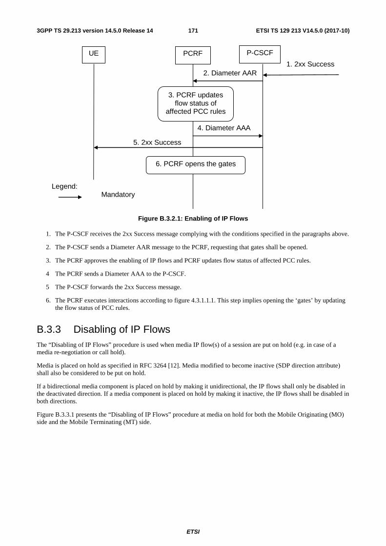
ETSI
ETSI TS 129 213 V14.5.0 (2017-10)1713GPP TS 29.213 version 14.5.0 Release 14
5. 2xx Success
4. Diameter AAA
2. Diameter AAR
PCRF P-CSCF
1. 2xx Success
6. PCRF opens the gates
3. PCRF updates flow status of
affected PCC rules
UE
Legend: Mandatory
Figure B.3.2.1: Enabling of IP Flows
1. The P-CSCF receives the 2xx Success message complying with the conditions specified in the paragraphs above.
2. The P-CSCF sends a Diameter AAR message to the PCRF, requesting that gates shall be opened.
3. The PCRF approves the enabling of IP flows and PCRF updates flow status of affected PCC rules.
4 The PCRF sends a Diameter AAA to the P-CSCF.
5 The P-CSCF forwards the 2xx Success message.
6. The PCRF executes interactions according to figure 4.3.1.1.1. This step implies opening the ‘gates’ by updating the flow status of PCC rules.
B.3.3 Disabling of IP Flows The “Disabling of IP Flows” procedure is used when media IP flow(s) of a session are put on hold (e.g. in case of a media re-negotiation or call hold).
Media is placed on hold as specified in RFC 3264 [12]. Media modified to become inactive (SDP direction attribute) shall also be considered to be put on hold.
If a bidirectional media component is placed on hold by making it unidirectional, the IP flows shall only be disabled in the deactivated direction. If a media component is placed on hold by making it inactive, the IP flows shall be disabled in both directions.
Figure B.3.3.1 presents the “Disabling of IP Flows” procedure at media on hold for both the Mobile Originating (MO) side and the Mobile Terminating (MT) side.
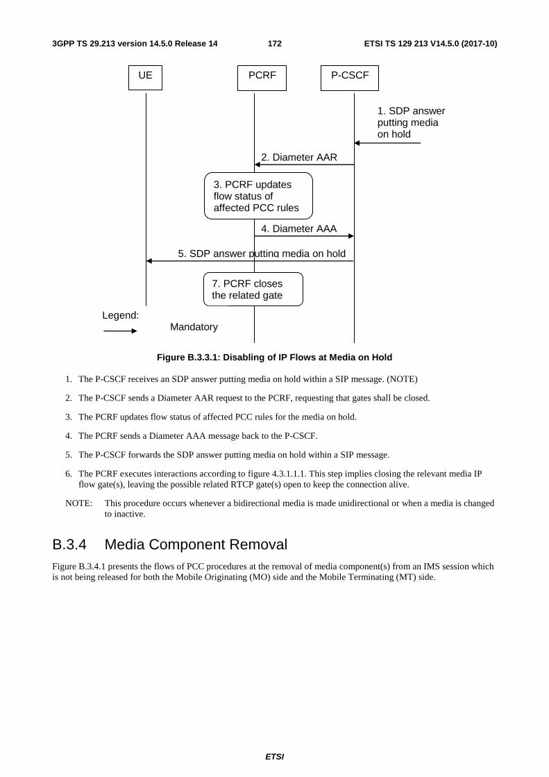
ETSI
ETSI TS 129 213 V14.5.0 (2017-10)1723GPP TS 29.213 version 14.5.0 Release 14
4. Diameter AAA
5. SDP answer putting media on hold
1. SDP answer putting media on hold
2. Diameter AAR
PCRF P-CSCF
3. PCRF updates flow status of affected PCC rules
7. PCRF closes the related gate
Legend: Mandatory
UE
Figure B.3.3.1: Disabling of IP Flows at Media on Hold
1. The P-CSCF receives an SDP answer putting media on hold within a SIP message. (NOTE)
2. The P-CSCF sends a Diameter AAR request to the PCRF, requesting that gates shall be closed.
3. The PCRF updates flow status of affected PCC rules for the media on hold.
4. The PCRF sends a Diameter AAA message back to the P-CSCF.
5. The P-CSCF forwards the SDP answer putting media on hold within a SIP message.
6. The PCRF executes interactions according to figure 4.3.1.1.1. This step implies closing the relevant media IP flow gate(s), leaving the possible related RTCP gate(s) open to keep the connection alive.
NOTE: This procedure occurs whenever a bidirectional media is made unidirectional or when a media is changed to inactive.
B.3.4 Media Component Removal Figure B.3.4.1 presents the flows of PCC procedures at the removal of media component(s) from an IMS session which is not being released for both the Mobile Originating (MO) side and the Mobile Terminating (MT) side.
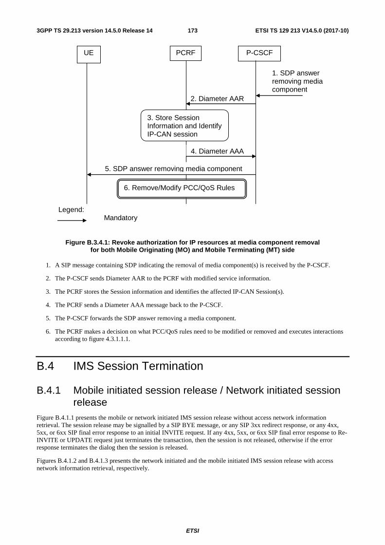
ETSI
ETSI TS 129 213 V14.5.0 (2017-10)1733GPP TS 29.213 version 14.5.0 Release 14
1. SDP answer removing media component
2. Diameter AAR
PCRF P-CSCF
3. Store Session Information and Identify IP-CAN session
6. Remove/Modify PCC/QoS Rules
5. SDP answer removing media component
Legend: Mandatory
4. Diameter AAA
UE
Figure B.3.4.1: Revoke authorization for IP resources at media component removal for both Mobile Originating (MO) and Mobile Terminating (MT) side
1. A SIP message containing SDP indicating the removal of media component(s) is received by the P-CSCF.
2. The P-CSCF sends Diameter AAR to the PCRF with modified service information.
3. The PCRF stores the Session information and identifies the affected IP-CAN Session(s).
4. The PCRF sends a Diameter AAA message back to the P-CSCF.
5. The P-CSCF forwards the SDP answer removing a media component.
6. The PCRF makes a decision on what PCC/QoS rules need to be modified or removed and executes interactions according to figure 4.3.1.1.1.
B.4 IMS Session Termination
B.4.1 Mobile initiated session release / Network initiated session release
Figure B.4.1.1 presents the mobile or network initiated IMS session release without access network information retrieval. The session release may be signalled by a SIP BYE message, or any SIP 3xx redirect response, or any 4xx, 5xx, or 6xx SIP final error response to an initial INVITE request. If any 4xx, 5xx, or 6xx SIP final error response to Re-INVITE or UPDATE request just terminates the transaction, then the session is not released, otherwise if the error response terminates the dialog then the session is released.
Figures B.4.1.2 and B.4.1.3 presents the network initiated and the mobile initiated IMS session release with access network information retrieval, respectively.
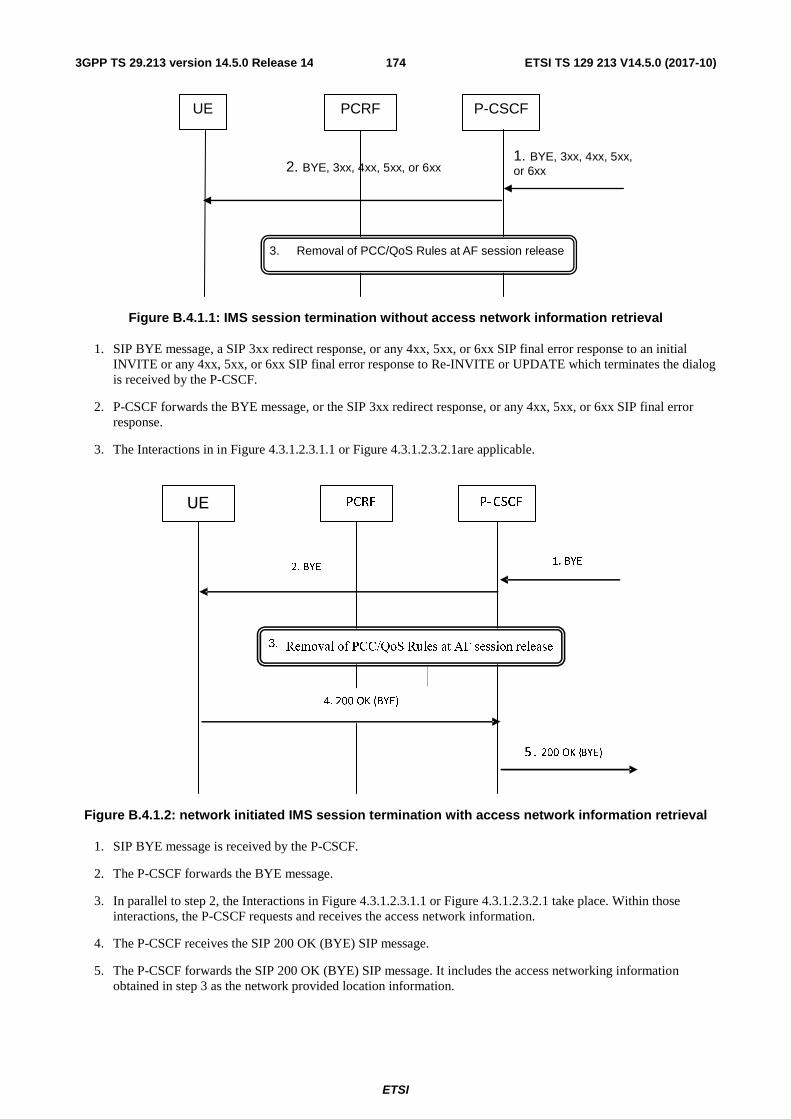
ETSI
ETSI TS 129 213 V14.5.0 (2017-10)1743GPP TS 29.213 version 14.5.0 Release 14
2. BYE, 3xx, 4xx, 5xx, or 6xx 1. BYE, 3xx, 4xx, 5xx, or 6xx
PCRF P-CSCF
3. Removal of PCC/QoS Rules at AF session release
UE
Figure B.4.1.1: IMS session termination without access network information retrieval
1. SIP BYE message, a SIP 3xx redirect response, or any 4xx, 5xx, or 6xx SIP final error response to an initial INVITE or any 4xx, 5xx, or 6xx SIP final error response to Re-INVITE or UPDATE which terminates the dialog is received by the P-CSCF.
2. P-CSCF forwards the BYE message, or the SIP 3xx redirect response, or any 4xx, 5xx, or 6xx SIP final error response.
3. The Interactions in in Figure 4.3.1.2.3.1.1 or Figure 4.3.1.2.3.2.1are applicable.
2. BYE1. BYE
PCRF P- CSCF
3. Removal of PCC/QoS Rules at AF session release
4. 200 OK (BYE)
5. 200 OK (BYE)
UE
Figure B.4.1.2: network initiated IMS session termination with access network information retrieval
1. SIP BYE message is received by the P-CSCF.
2. The P-CSCF forwards the BYE message.
3. In parallel to step 2, the Interactions in Figure 4.3.1.2.3.1.1 or Figure 4.3.1.2.3.2.1 take place. Within those interactions, the P-CSCF requests and receives the access network information.
4. The P-CSCF receives the SIP 200 OK (BYE) SIP message.
5. The P-CSCF forwards the SIP 200 OK (BYE) SIP message. It includes the access networking information obtained in step 3 as the network provided location information.

ETSI
ETSI TS 129 213 V14.5.0 (2017-10)1753GPP TS 29.213 version 14.5.0 Release 14
Figure B.4.1.3: mobile initiated IMS session termination with access network information retrieval
1. SIP BYE message is received by the P-CSCF.
2. The Interactions in Figure 4.3.1.2.3.1.1 or Figure 4.3.1.2.3.2.1 are applicable. Within those interactions, the P-CSCF requests and receives the access network information.
3. The P-CSCF forwards the BYE message. It includes the access network information obtained in step 2 as the network provided location information.
B.4.2 IP-CAN Bearer Release/Loss An IP-CAN Bearer Release or Loss event may affect all IP-Flows within an IMS Session. Flows in clause 4.3.2.2.1 (AF located in the HPLMN) or 4.3.2.2.2 (AF located in the VPLMN) apply for case 1. Flows in clause 4.4.2.1.1 (Home Routed case) or 4.4.2.2.1 (Visited Access case) apply for case 2a and case 2b.
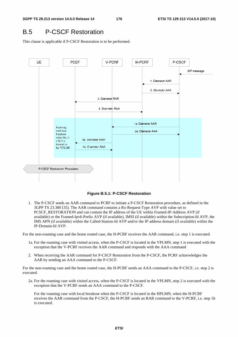
ETSI
ETSI TS 129 213 V14.5.0 (2017-10)1763GPP TS 29.213 version 14.5.0 Release 14
B.5 P-CSCF Restoration This clause is applicable if P-CSCF Restoration is to be performed.
Figure B.5.1: P-CSCF Restoration
1. The P-CSCF sends an AAR command to PCRF to initiate a P-CSCF Restoration procedure, as defined in the 3GPP TS 23.380 [35]. The AAR command contains a Rx-Request-Type AVP with value set to PCSCF_RESTORATION and can contain the IP address of the UE within Framed-IP-Address AVP (if available) or the Framed-Ipv6-Prefix AVP (if available), IMSI (if available) within the Subscription-Id AVP, the IMS APN (if available) within the Called-Station-Id AVP and/or the IP address domain (if available) within the IP-Domain-Id AVP.
For the non-roaming case and the home routed case, the H-PCRF receives the AAR command, i.e. step 1 is executed.
1a. For the roaming case with visited access, when the P-CSCF is located in the VPLMN, step 1 is executed with the exception that the V-PCRF receives the AAR command and responds with the AAA command
2. When receiving the AAR command for P-CSCF Restoration from the P-CSCF, the PCRF acknowledges the AAR by sending an AAA command to the P-CSCF.
For the non-roaming case and the home routed case, the H-PCRF sends an AAA command to the P-CSCF, i.e. step 2 is executed.
2a. For the roaming case with visited access, when the P-CSCF is located in the VPLMN, step 2 is executed with the exception that the V-PCRF sends an AAA command to the P-CSCF.
For the roaming case with local breakout when the P-CSCF is located in the HPLMN, when the H-PCRF receives the AAR command from the P-CSCF, the H-PCRF sends an RAR command to the V-PCRF, i.e. step 1b is executed.

ETSI
ETSI TS 129 213 V14.5.0 (2017-10)1773GPP TS 29.213 version 14.5.0 Release 14
3. When receiving the AAR command for P-CSCF Restoration, the PCRF finds the corresponding IP-CAN session according to the received information within the AAR command, and sends an RAR command for the corresponding IP-CAN session (IMS PDN connection) to the PCEF for P-CSCF Restoration. The RAR contains a PCSCF-Restoration-Indication AVP with value set to PCSCF_RESTORATION.
For the non-roaming case and the home routed case, when receiving the AAR command from the P-CSCF, the H-PCRF sends the RAR command to the PCEF, i.e. step 3 is executed.
3a, For the roaming case with visited access, when the P-CSCF is located in the VPLMN, step 3 is executed with the exception that when receiving the AAR command from the P-CSCF, the V-PCRF sends the RAR command to the PCEF.
For the roaming case with local breakout when the P-CSCF is located in the HPLMN, when receiving the RAR command from the H-PCRF, the V-PCRF sends an RAR command to the PCEF, i.e. step 2a is executed.
4. When receiving the RAR command for P-CSCF Restoration, the PCEF acknowledges the RAR by sending an RAA command to the PCRF and performs the subsequent P-CSCF Restoration procedure as specified in 3GPP TS 23.380 [35].
NOTE 1: If the IMS PDN disconnection is performed for P-CSCF Restoration, the PCEF sends a CCR command to the PCRF to terminate the corresponding Gx session.
For the non-roaming case and the home routed case, when receiving the RAR command from the H-PCRF, the PCEF acknowledges this message by sending an RAA command to the H-PCRF, i.e. step 4 is executed.
4a. For the roaming case with visited access, when the P-CSCF is located in the VPLMN, step 4 is executed with the exception that when receiving the RAR command from the V-PCRF, the PCEF acknowledges this message by sending an RAA command to the V-PCRF.
NOTE 2: This P-CSCF Restoration procedure is applicable to the cases that both the P-CSCF and the PCEF are located in the same PLMN.

ETSI
ETSI TS 129 213 V14.5.0 (2017-10)1783GPP TS 29.213 version 14.5.0 Release 14
Annex C (normative): NAT Related Procedures
C.1 Support for media traversal of NATs using ICE The IMS calls out procedures for NAT traversal for media and 178vailabili within IMS. One of the methods supported by IMS for media traversal of NATs is a UE controlled NAT traversal solution based on the IETF Interactive Connectivity Establishment (ICE) protocol, IETF RFC 5245 [15]. When a UE uses the ICE protocol for media traversal of NATs, additional enhancements to the existing PCC procedures are necessary to allow for proper ICE operation.
This annex presents a set of rules that PCC network elements use to build flow descriptors, identify the proper UE IP addresses used by the PCRF for session and bearer binding, and gating control when the ICE procedures are invoked by the UE.
In order for the ICE procedures to work a static, preconfigured PCC rule needs to be in place at the PCEF which allows the UE to perform STUN binding requests prior to offering or answering an SDP.
NOTE 1: Predefined PCC rules can be created to allow the UE to communicate with the STUN relay much in the same way the UE is allowed to communicate with the IMS network for session management.
NOTE 2: Given that a STUN relay is a forwarding server under the direction of the UE, necessary precaution needs to be taken by the operator in how it chooses to craft these rules. It is recommended that such predefined rules only guarantee the minimal amount of bandwidth necessary to accomplish the necessary UE to STUN relay communication. Such an approach helps reduce the resources required to support NAT traversal mechanisms. Finally, such an approach allows the preconfigured rule to be over-ridden by dynamic rules which allow for the necessary bandwidth needed by the session.
NOTE 3: The dynamic PCC rule will need to differentiate between different media traffic between UE and STUN relay (e.g. voice vs. video), which can be identified by the different ports assigned by the residential NAT. Session bindings need to take into account that the relevant terminal IP address may be contained within the ICE candidates contained in the session description, rather than in the normal media description.
NOTE 4: It is assumed that the NAT device is located between the UE and the PCEF. NAT traversal outside of IMS in FBI services is considered FFS in the current 3GPP stage 2 specifications.
NOTE 5: When a NAT device is located between the UE and the PCEF, it is assumed that the IP CAN session signalling will contain the IP address assigned by the residential NAT, rather than the UE IP address.
NOTE 6: It is assumed that NAT devices that assign multiple IP addresses for the UE are outside the scope of release 7.
NOTE 7: In this release, only one IP address per subscription is supported by session binding at the PCRF. Multiple Ues behind a NAT will use the same IP CAN session and IP address.
C.2 P-CSCF procedures
C.2.1 General The procedures in clause C.2 are only invoked in the case where the local UE (uplink SDP) has utilized the ICE protocol for media traversal of NATs. The P-CSCF can determine this by inspecting the UE provided SDP (uplink) for the “a=candidate” attribute(s). If such attributes are present this is an indication that the UE has invoked the ICE procedures as defined in IETF RFC 5245 [15] for media traversal of NATs and the P-CSCF shall follow the requirements in clause C.2.

ETSI
ETSI TS 129 213 V14.5.0 (2017-10)1793GPP TS 29.213 version 14.5.0 Release 14
C.2.2 Deriving the Ues IP address The P-CSCF shall set the Framed-IP-Address AVP or Framed-Ipv6-Prefix AVP to the source IP address of SIP messages received from the UE.
C.2.3 Deriving flow descriptions In the case where STUN Relay and ICE are used for NAT traversal, the UE is required to place the STUN Relay provided address in the “m=” and “c=” lines of its SDP. Given that these addresses cannot be used by the P-CSCF for building a valid flow description, the P-CSCF will need to determine if a STUN Relay address has been provided in the “m=” and “c=” lines of the UE provided SDP (uplink only). The P-CSCF shall make this determination by inspecting the uplink SDP for “a=candidate” attributes and compare the candidate address with that contained in the “c=” line. If a match is found, the P-CSCF shall then look at the candidate type. If the candidate type is “relay” then the address in the “c=” line is that of a STUN Relay server. In this case, the P-CSCF shall derive the Flow-Description AVP within the service information from the SDP candidate type of “relay” as follows:
Uplink Flow-Description
- Destination Address and Port: If the P-CSCF knows the destination address and port of the STUN Relay allocation that the UE is sending media to, it should use that information. If the P-CSCF does not know this address and port, it shall wildcard the uplink destination address and port.
- Source Address and Port: The P-CSCF shall populate the uplink source address with the “rel-addr” address and the uplink source port with the “rel-port” port contained within the “a=candidate” attribute.
Downlink Flow-Description
- Destination Address and Port: The P-CSCF shall populate the downlink destination address with the “rel-addr” address and the downlink destination port with the “rel-port” port contained within the “a=candidate” attribute.
- Source Address and Port: If the P-CSCF knows the source address and port of the STUN Relay allocation that the UE is receiving media from, it should use that information. If the P-CSCF does not know this address and port, it shall wildcard the downlink source address and port.
For the other candidate types, the address in the “c=” and “m=” SDP attributes can be used for building the flow descriptor and the P-CSCF shall follow the rules to derive the Flow-Description AVP as described in table 6.2.2 of clause 6.2 of this TS.
C.2.4 Gating control If both endpoints have indicated support for ICE (both the SDP offer and answer contain SDP attributes of type “a=candidate”) ICE connectivity checks will take place between the two Ues. In order to allow these checks to pass through the PCEF, the P-CSCF shall enable each flow description for each media component upon receipt of the SDP answer.
C.2.5 Bandwidth impacts ICE has been designed such that connectivity checks are paced inline with RTP data (sent no faster than 20ms) and thus consumes a lesser or equal amount of bandwidth compared to the media itself (given the small packet size of a STUN connectivity check it is expected that the STUN connectivity checks will always have a smaller payload than the media stream itself). Thus, there are no additional requirements on the P-CSCF for bandwidth calculations for a given media flow.

ETSI
ETSI TS 129 213 V14.5.0 (2017-10)1803GPP TS 29.213 version 14.5.0 Release 14
C.3 PCRF procedures
C.3.1 General The procedures in clause C.3 are only invoked when the following two conditions are met:
1. Both the local and remote UE have utilized the ICE protocol for media traversal of NATs (see clause C.2.1 for details on how this is determined); and
2. The IP-CAN which is servicing the IMS session does not support the concept of a default bearer.
C.3.2 Deriving additional flow descriptions The PCRF may need to develop additional flow descriptions (beyond those provided by the P-CSCF) for a media component based on additional candidate addresses present in the SDP offer/answer exchange. The PCRF shall follow the procedures defined in IETF RFC 5245 [15] for forming candidate pairs based on the data contained within the received codec-data AVP. For each candidate pair created based on the ICE procedures and not already present in the received flow descriptions, the PCRF shall add an uplink and downlink flow description for each media component.
NOTE 1: The uplink SDP represents the local candidates while the downlink SDP represents the remote candidates.
Following the ICE procedures for forming candidate pairs will result in some flow descriptions which would never be exercised. In particular, while the UE will send connectivity checks (and ultimately its media stream) from its host candidate, from the PCEF perspective, this will appear as being from the server reflexive address. Given this, the PCRF should not form flow descrptions using host candidate addresses and should only form additional flows based on server reflexive addresses and relay addresses.
As candidates are removed from the SDP via subsequent offer/answer exchanges, the PCRF shall update its candidate pair list and shall remove any flow descriptors no longer being used.
NOTE 2: If the default candidate (the candidate used to populate the “c=” and “m=” lines of both the uplink and downlink SDP) is chosen, then an updated SDP offer/answer will not be done, and any extra flow descriptions not being used by the session will not be removed.
C.3.3 Gating control For each additional flow description the PCRF adds to a media component (per clause C.3.2), the PCRF shall enable the flow in order to allow connectivity checks to pass.
C.3.4 Bandwidth impacts Per clause C.2.5 ICE is designed to have minimal impact on bandwidth policy control. However, it is possible that media will begin flowing while the ICE connectivity checks are still in progress. Given the possibility that no session update will be made (the default candidates will be chosen by the ICE protocol), it is not recommended that the PCRF adjust the bandwidth parameters provided by the P-CSCF.
C.4 P_CSCF procedures to support media traversal through hosted NAT without ICE
Both the media flows and the SIP signalling can traverse a NA(P)T device located in the customer premises domain, or “hosted NAT”, as described in Annex F of 3GPP TS 24.229 [5]. The hosted NAT will modify the source IP address and source port of uplink IP packets, and the destination IP address and port of downlink IP packets. The IP addess and port information provided by the UE are thus not appropriate to configure PCC rules.
The UE may use ICE procedures for hosted NAT traversal, and related PCC procedures are described in clauses C.1 to C.3. The present clause provides procedures to cover the case where ICE is not used.
ETSI
ETSI TS 129 213 V14.5.0 (2017-10)1813GPP TS 29.213 version 14.5.0 Release 14
If the P-CSCF determines that the UE is located behind a hosted NAT (using procedures in Annex F of 3GPP TS 24.229 [5]) and that ICE is not used (using procedures in clause C.2.1), the P-CSCF shall, within the service information sent to the PCRF:
- provide the source IP address of IP packets transporting incoming SIP messages from the UE as destination IP address of downlink media streams;
- for Ipv4, provide the source IP address of IP packets transporting incoming SIP messages from the UE as source address of uplink media streams;
- for Ipv6, derive the source address of uplink media streams from the prefix of the source IP address of IP packets transporting incoming SIP messages from the UE;
- wildcard source ports of uplink media streams; and
- wildcard destination ports of downlink media streams.
- provide the port information within SDP sent towards the served UE as source ports of corresponding downlink media streams.
- provide the port information within SDP sent towards the served UE as destination ports of corresponding uplink media streams.

ETSI
ETSI TS 129 213 V14.5.0 (2017-10)1823GPP TS 29.213 version 14.5.0 Release 14
Annex D (normative): Access specific procedures for GPRS
D.1 General The present annex defines IP-CAN specific requirements for General Packet Radio Service (GPRS).
D.2 Binding Mechanisms Depending on the bearer control mode, bearer binding can be executed either by PCRF, PCEF or both PCRF and PCEF.
- For “UE-only” IP-CAN bearer establishment mode, the PCRF performs bearer binding.
- For “UE/NW” IP-CAN bearer establishment mode, the PCRF performs the binding of the PCC rules for user controlled services while the PCEF performs the binding of the PCC rules for the network controlled services.
If the PCEF performs the bearer binding, the PCRF shall follow the procedures as described in clause 5.4 with the exceptions described in this subclause.
If the Bearer Binding function is located at the PCEF, the PCEF shall check the QCI and ARP indicated by the PCC Rule(s) and bind the PCC rule with an IP-CAN bearer that has the same QCI and Evolved ARP (if this is supported by the SGSN).
If there is no suitable PDP-Context to accommodate a PCC rule when PCEF performs the bearer binding, the PCEF shall initiate the establishment of PDP-Contexts as specified in 3GPP TS 23.060 [3].
The PCEF shall not combine PCC rules with different ARP to the same bearer. If the Evolved ARP parameter is not supported by the SGSN, the PCEF shall map the Evolved ARP to Rel-99 ARP as specified in clause B.3.3.3 of 3GPP TS 29.212 [9].
NOTE: If Evolved ARP is not supported by the SGSN then this enables a modification of the PDP context ARP without impacting the bearer binding after relocation to a SGSN that supports Evolved ARP.
If the Bearer Binding function is located at the PCRF, the PCRF shall compare the TFT(s) of all IP-CAN bearer(s) within the IP-CAN session received via PCEF from the UE with the existing service data flow filter information. The PCRF shall indicate to the PCEF the IP-CAN bearer within the IP-CAN session where the PCC Rules shall be installed, modified or removed. This is done including the Bearer-Identifier AVP together with the associated PCC Rules within the corresponding RAR and/or CCA commands.
- When the PCRF does not require additional filter information coming from the UE in order to decide on bearer binding, the PCRF shall supply the PCC rules to be installed over the Gx interface to the PCEF within a RAR command.
- Otherwise, the PCRF shall wait for the PCEF requesting a policy decision for the establishment of a new IP-CAN bearer or the modification of an existing one within a CCR command over the Gx interface.
- When the PCEF reports the bearer event, it shall include within the CCR command a bearer reference together with the new or modified TFT information, the QCI and associated bitrates for new or modified PDP-Contexts.

ETSI
ETSI TS 129 213 V14.5.0 (2017-10)1833GPP TS 29.213 version 14.5.0 Release 14
D.3 PCC Procedures
D.3.1 IP-CAN Session Modification
D.3.1.1 Network-initiated IP-CAN Session Modification
Network-initiated IP-CAN session modification is executed according to clause 4.3.1.1 with the following differences:
- The timer in step 4 will also be activated waiting for one of the following cases:
- If the authorized QoS for an IP-CAN bearer is changed or
- If one or more Flow Descriptions need to be added, deactivated or removed in any of the PCC rules bound to an IP-CAN bearer
- If the timer in step 4 expires and the PCRF still requires additional filter information coming from the UE in order to decide on bearer binding for new PCC rules to be installed, all subsequent steps in figure 4.3.1.1.1 shall not be executed, and further reactions of the PCRF are left unspecified. As a possible option, the PCRF could abort the AF session.
- When the PCRF performs the bearer binding, once the PCC rules are selected, the PCRF identifies the IP-CAN bearer for each of the PCC rules and the authorized QoS. The PCRF may provision PCC Rules and authorized QoS for several IP-CAN Bearers within the same RAR command.
- For step 9, IP-CAN session signalling, the subsequent steps are executed separately for each IP-CAN bearer under the following conditions:
- if all PCC rules bound to a PDP context have been removed or deactivated (PDP Context deactivation is applicable)
- if one or more PDP contexts have to be modified
- if in UE/NW Bearer Control Mode, the GGSN needs to establish a new PDP context(PDP Context establishment is applicable) if the bearer binding is located at the PCEF.
The GGSN initiates the procedure to Create/Update or Terminate PDP Context Request message to the SGSN. If in the case of updating the PDP Context the authorized QoS for the bearer has changed, the GGSN will modify the UMTS QoS parameters accordingly.
When the procedure in step 9 is completed and requires notifications from the GW, for an IP-CAN Bearer termination in UE-Only Bearer Control Mode, the GGSN sends a Diameter CCR with the Bearer-Identifier and Bearer-Operation AVPs to indicate “Termination”.
D.3.1.2 PCEF-initiated IP-CAN Session Modification
PCEF-initiated IP-CAN Session Modification procedure shall take place according to clauses 4.3.2.1 and 4.3.2.2 except for those procedures initiated by the UE, as described in the clauses below.
D.3.1.2.1 UE-initiated IP-CAN Bearer Establishment or IP-CAN Bearer Modification
This clause is applicable for the establishment of a new IP-CAN Bearer (other than the one which created the IP-CAN session) and for the modification of an already established IP-CAN Bearer. The signalling flows for these cases are as per Figure 4.3.1.2.1.
A bearer-event-initiated Request of PCC Rules occurs when a new bearer is established or when an existing bearer is modified. For GPRS, these are PDP Context Modification(s) or secondary PDP context Activation(s). An IP-CAN Session modification triggers a PCC Rule request only if the PCRF has previously requested a PCC Rule request for the given modification event.

ETSI
ETSI TS 129 213 V14.5.0 (2017-10)1843GPP TS 29.213 version 14.5.0 Release 14
PCRF GW
2. Diameter CCR
11. Diameter CCA
9. PCC Rules Decision, Policy Decision
4. Bind IP CAN session to any existing AF session(s)
3. Store Bearer Information
10. Store PCC Rules
SPR
5. Profile Request
6. Profile Response
For GPRS, for each affected other bearer where previous authorized QoS is modified(because IP Flow(s) were moved to other bearer(s))
1. IP-CAN Bearer signalling
13. IP CAN Bearer signalling response
12. Installation Modification or Removal of PCC Rules, Policy Enforcement
Legend:
Mandatory
Conditional
AF
7. Diameter RAR
8. Diameter RAA
If the PCRF needs subscription- related information and does not have it
For IP CAN session modification, if requested by AF at initial authorisation
14. Start of Timer.
15. Interactions in Figure 4.3.1.1.1
Figure D.3.1.2.1: UE-initiated IP-CAN Bearer Establishment and Modification.
1. The GW receives IP-CAN Bearer signalling that is a trigger for a PCC Rule request. For GPRS, the GGSN receives a secondary Establish PDP Context Request or an Update PDP Context Request.
2. The GW informs the PCRF of the modification of the IP-CAN Session due to the IP-CAN Bearer signalling in step 1, using a Diameter CCR with the CC-Request-Type AVP set to the value UPDATE_REQUEST. The GW reuses the existing Gx DCC session corresponding to the IP-CAN Session.
If the IP-CAN Bearer signalling in step 1 established a new IP-CAN Bearer, the GW assigns a new bearer identifier to this IP-CAN Bearer. The GW provides information about the new or modified bearer, e.g. requested QoS and TFT filters. If the event that caused the bearer modification applies uniquely to that bearer and PCRF performs the bearer binding, then, the bearer identifier should be provided within the CCR. If no bearer identifier is provided, the event trigger will apply to the IP-CAN session.

ETSI
ETSI TS 129 213 V14.5.0 (2017-10)1853GPP TS 29.213 version 14.5.0 Release 14
3. The PCRF stores the received information in the Diameter CCR.
4. The PCRF binds the IP-CAN Session to existing of AF session(s) using the information received from the GW and the Service Information included in the stored PCC rules, which was previously received from the AF(s) , as depicted in figure 4.3.1.1.1. The PCRF also binds the IP-CAN Bearers within the IP-CAN Session to all matching IP flow(s) of existing AF session(s) using the bearer information received from the GW and the Service Information received from the AF(s). If IP flow(s), which have previously been bound to other bearers, have been bound to the modified bearer, PCC Rules in other bearer(s) may need to be removed. For GPRS, an IP flow may need to be removed if a matching higher priority TFT filter in the newly established PDP context takes precedence over a matching lower priority TFT filter in another PDP context. Furthermore, if IP Flow(s), which have previously been bound to the modified bearer are be bound to other bearer(s), PCC Rules may need to be installed in other bearers. For GPRS, an IP flow may be bound to another PDP context if it was previously bound to the modified PDP context due to a removed higher priority TFT filter, and a lower priority TFT filter in the other PDP context matches the IP flow.
5. If the PCRF requires subscription-related information and does not have it, the PCRF sends a request to the SPR in order to receive the information.
6. The SPR replies with the subscription related information containing the information about the allowed service(s) and PCC Rules information.
NOTE: For steps 5 and 6: The details associated with the Sp reference point are not specified in this Release. The SPR’s relation to existing subscriber databases is not specified in this Release.
7. For IP CAN session modification, if the AF requested a notification of the corresponding event at the initial authorisation of the AF session, the PCRF shall sent a Diameter RAR with the Specific-Action AVP set to indicate the trigger event that caused the request.
8. If step 7 happens, the AF replies with a Diameter RAA and may provide updated service information within.
9. The PCRF selects the new PCC Rule(s) to be installed. The PCRF can also identify existing PCC Rules that need to be modified or removed. The PCC Rules may relate to any of the matching AF sessions identified in step 4 or may exist in the PCRF without matching to any AF session. The PCRF may also make a policy decision by defining an authorized QoS and by deciding whether service flows described in the PCC Rules are to be enabled or disabled. For types of IP-CAN, where the PCRF controls IP-CAN Bearers, e.g. GPRS, the PCC Rules may affect the IP-CAN Bearer identified in the CCR of step 2 or any other IP-CAN Bearer identified in step 4.
10. The PCRF stores the modified PCC Rules.
11. The PCC Rules are provisioned by the PCRF to the GW using Diameter CCA. The PCRF may also provide authorized QoS. The PCRF identifies the affected IP-CAN Bearer for each of the PCC Rules and the authorized QoS. The PCRF may provision PCC Rules and authorized QoS for several IP-CAN Bearers within the same CCA.
12. The GW installs the received PCC Rules. The GW also enforces the authorized QoS and enables or disables service flow according to the flow status of the corresponding PCC Rules.
13. The GW sends a response to the IP-CAN Bearer signalling in step 1. For GPRS, the GGSN accepts the secondary Establish PDP Context Request or the Update PDP Context Request based on the results of the authorisation policy decision enforcement and sends an Establish PDP Context Response or Update PDP Context Response. If the requested QoS parameters do not correspond to the authorized QoS, the GGSN adjusts (downgrades/upgrades) the requested UMTS QoS parameters to the authorized values.
The PCRF may have decided in step 4 to modify PCC Rules and/or authorized QoS of other IP CAN bearers than the IP-CAN Bearer identified in the CCR of step 2. For each such other IP-CAN Bearer identified in step 4, the GGSN executes the following steps.
14. The PCRF may start a timer to wait for PDP context modification requests from the UE.
15. The PCRF interacts with the GW according to figure 4.3.1.1.1.

ETSI
ETSI TS 129 213 V14.5.0 (2017-10)1863GPP TS 29.213 version 14.5.0 Release 14
D.3.1.2.2 UE-initiated IP-CAN Bearer Termination
This clause is applicable if an IP-CAN Bearer is being released while other IP-CAN Bearers and thus the IP-CAN Session are not released.
For the termination of IP-CAN Bearers, three cases are covered:
- Bearer release that does not cause service data flow(s) within an AF session to be disabled;
- Bearer release that causes at least one but not all the service data flow(s) within an AF session to be disabled; and
- Bearer release that causes all the service data flows within an AF session to be disabled.
A Bearer release may not cause a service data flow within this bearer to be disabled if the IP flow can be bound to another bearer. For GPRS, an IP flow can be bound to another PDP context if a lower precedence TFT filter matching the IP flow is installed at the other PDP context.

ETSI
ETSI TS 129 213 V14.5.0 (2017-10)1873GPP TS 29.213 version 14.5.0 Release 14
13a. Diameter AAA
12a. Diameter AAR
11. Diameter ASA
10. Diameter ASR
GW PCRF AF
2. Diameter CCR
If all the service data flows within AF session are affected
6. Diameter CCA
If not all the service data flows within AF session are affected
11a. Diameter RAA
10a. Diameter RAR
13. Diameter STA
12. Diameter STR
3. Identify the IP flows bound to the session or bearer.
1. Remove IP-CAN Bearer Request
7. Remove PCC Rules
8. Remove IP-CAN Bearer Response
If IP Flow(s) were moved to other bearer(s)
4. PCC Rules Decision. Policy Decision
5. Store PCC Rules
9. Install PCC Rules. Policy Enforcement
If IP Flow(s) were moved to other bearer(s)
Legend:
Mandatory
Conditional
Figure D.3.1.2.2: UE-Initiated IP-CAN Bearer Termination

ETSI
ETSI TS 129 213 V14.5.0 (2017-10)1883GPP TS 29.213 version 14.5.0 Release 14
1. The GW receives a Remove IP-CAN Bearer Request that request the deactivation of an IP-CAN Bearer while other IP-CAN Bearers and thus the IP-CAN Session are not released. The form of the Remove IP-CAN Bearer Request depends upon the type of the IP-CAN. For GPRS, the GGSN receives a Delete PDP Context Request.
2. The GW sends a Diameter CCR message with the CC-Request-Type AVP set to the value UPDATE_REQUEST to the PCRF, indicating the IP-CAN Bearer termination.
3. The PCRF identifies the IP flows bound to the removed bearer and updates the stored bearer information. The PCRF re-evaluates the binding of IP flows, as IP flows may now be bound to other bearers. For GPRS, an IP flow may be bound to another PDP Context if it was previously bound to the removed PDP context due to a higher priority TFT filter, and a lower priority TFT filter in another PDP context matches the IP flow.
The following steps 4 and 5 are performed for each of the other bearers identified in step 3:
4. The PCRF selects the PCC Rule(s) to be installed or modified for the affected bearer. The PCRF may also update the policy decision for this bearer.
5. The PCRF stores the updated PCC Rules for the affected bearer.
6. The PCRF acknowledges the bearer termination by sending a Diameter CCA message. The PCRF provides PCC Rules and possibly updated authorized QoS for each of the other bearers identified in step 3. The PCRF identifies the affected IP-CAN Bearer for each of the PCC Rules and the authorized QoS.
7. The GW removes those PCC Rules, which have not been moved to other IP CAN bearers by the CCA message and are installed in the IP-CAN bearer, for which a termination has been requested in step 1.
8. The GW sends a Remove IP-CAN Bearer Response. For GPRS, the GGSN sends the Delete PDP Context Response message.
9. It the PCRF has provided PCC Rules and possibly updated authorized QoS for other bearers in step 6, the GW installs or modifies the identified PCC Rules. The GW also enforces the authorized QoS and enables or disables service flow according to the flow status of the corresponding PCC Rules.
The following steps 10 to 13 or 10a to 13a apply for the case where at least one IP Flow within an AF session is being disabled, i.e. if the IP Flow is not bound to any other bearer that is still established. The steps shall be performed separately for each ongoing AF session that is affected by the bearer release as explained below.
If all IP flow(s) within the AF session are disabled by the bearer release:
10. The PCRF indicates the session abort to the AF by sending a Diameter ASR message to the AF.
11. The AF responds by sending a Diameter ASA message to the PCRF.
12. The AF sends a Diameter STR message to the PCRF to indicate that the session has been terminated.
13. The PCRF responds by sending a Diameter STA message to the AF.
If at least one but not all of the IP flow(s) within the AF session are disabled by the bearer release, and the AF has requested notification of bearer removal:
10a. The PCRF indicates the release of the bearer by sending a Diameter RAR to the AF.
11a. The AF responds by sending a Diameter RAA to the PCRF.
12a. The AF may send an AAR to the PCRF to update the session information.
13a. If step 12a occurs, the PCRF responds by sending a AAA to the AF.

ETSI
ETSI TS 129 213 V14.5.0 (2017-10)1893GPP TS 29.213 version 14.5.0 Release 14
Annex E (normative): Fixed Broadband Access Interworking with EPC
E.1 General The present annex defines specific requirements for Fixed Broadband Access Interworking with EPC.
E.2 Definitions and abbreviations
E.2.1 Definitions UE local IP address is defined as: either the public Ipv4 address and/or Ipv6 address/Ipv6 network prefix assigned to the UE by the BBF domain in the no-NAT case, or the public Ipv4 address assigned by the BBF domain to the NATed RG that is used for this UE.
H(e)NB local IP address is defined as: either the public Ipv4 address and/or Ipv6 address/Ipv6 network prefix assigned to the H(e)NB by the BBF domain in the no-NAT case, or the public Ipv4 address assigned by the BBF domain to the NATed RG that is used for this H(e)NB.
Non-seamless WLAN offload (NSWO) is defined as: a capability of routing specific IP flows over the WLAN access without traversing the EPC as defined in clause 4.1.5 of 3GPP TS 23.402 [21].
Non-seamless WLAN offload APN (NSWO-APN) is defined as: an APN allowing the BPCF to indicate to PCRF that for subscribers of a certain HPLMN the IP-CAN session is related to NSWO traffic.
EPC-routed traffic is defined as: User plane traffic that is routed via a PDN GW in EPC as part of a PDN Connection. EPC-routed traffic applies to non-roaming, roaming with home routed and roaming with visited access cases.
E.2.2 Abbreviations The following abbreviations are relevant for this annex only:
BBF Broadband Forum BPCF Broadband Policy Control Function NA(P)T Network Address (Port) Translation NSWO Non-Seamless WLAN offload NSWO-APN Non-Seamless WLAN offload APN RG Residential Gateway
E.3 Binding Mechanisms
E.3.1 EPC-routed traffic For EPC- routed traffic, binding mechanisms apply as defined insub clause 5.1 by PCRF, PCEF and BBERF. In addition, if both a Gx and associated S9a session exist for the same IP-CAN session, the PCRF shall generate QoS Rules for all the authorized PCC rules.
E.3.2 NSWO traffic The binding mechanism includes two steps for the NSWO traffic:
1. Session binding.
ETSI
ETSI TS 129 213 V14.5.0 (2017-10)1903GPP TS 29.213 version 14.5.0 Release 14
2. PCC rule authorization.
For NSWO traffic, session binding of AF session to an IP-CAN session is performed by the PCRF for the purpose of policy control in the Fixed Broadband access network.
When the PCRF accepts an AA-Request from the AF over the Rx interface with service information, the PCRF shall perform session binding and associate the described service IP flows within the AF session information (and therefore the applicable PCC rules) to one and only one existing IP-CAN session. This association is done comparing the user IP address received via the Rx interface in either the Framed-IP-Address AVP or the Framed-Ipv6-Prefix AVP with the Ipv4 address or Ipv6 address/Ipv6 prefix received via the S9a or S9 interface. The user identity if present in the Subscription-Id AVP and the PDN information if available in the Called-Station-Id AVP may also assist on this association.
The PCRF determines that the UE has an IP-CAN session if the IP address (Ipv4 or Ipv6) received over the Rx interface matches the Ipv4 address or Ipv6 address/Ipv6 prefix received via one or more of the following interfaces: S9a interface and S9 interface, and if the user identity is used to assist the association, the user identity received over the Rx interface matches the user identity received via one or more of the following interfaces: S9a interface and S9 interface.
NOTE 1: In case the user identity in the IP-CAN and the application level identity for the user are of different kinds, the PCRF needs to obtain the mapping between the identities. Such mapping is not subject to specification within this TS.
NOTE 2: An Ipv6 address provided over Rx matches an Ipv6 prefix provided over S9a or S9 if the Ipv6 address belongs to the Ipv6 (sub-)network prefix.
As a result from the session binding function, the PCRF identifies what IP-CAN session the current AF session is related with. If the PCRF is not capable of executing the Session Binding, the PCRF shall issue an AA-Answer command to the AF with a negative response.
NOTE: For roaming cases, the H-PCRF performs session binding of the AF session to an IP-CAN session.
The PCRF derives and authorises PCC rules as described in clause 5.
E.4 PCC Procedures
E.4.1 Introduction From the network scenarios listed in clause 4.0, in order to support interworking with Fixed Broadband access network, three distinct network scenarios are defined as follows:
- the Case 1 (no Gateway Control Session over Gxx reference point) applies to GTP-based S2a or GTP-based S2b, trusted S2c and GTP-based S5/S8 H(e)NB scenarios.
- the Case 2a (the same Gateway Control Session over Gxx reference point) applies to untrusted S2c.
- the Case 2b (a Gateway Control Session over Gxx reference point per IP-CAN Session) applies to PMIP-based S2b and PMIP-based S5/S8 H(e)NB scenarios.
NOTE: No policy interworking solution based on S9a is defined for Fixed Broadband access interworking via S2a in this Release.
Additionally, for case 1, the PCRF checks whether the CoA information is included in the CC-Request command to differentiate the GTP-based S2b case and trusted S2c case. If it is included, the trusted S2c case applies; otherwise, the GTP-based S2b case applies.

ETSI
ETSI TS 129 213 V14.5.0 (2017-10)1913GPP TS 29.213 version 14.5.0 Release 14
E.4.2 IP-CAN Session Establishment
E.4.2.1 IP-CAN Session Establishment for EPC- routed traffic
This procedure is applicable for WLAN and H(e)NB scenarios for EPC-routed traffic. This procedure is same as described in clause 4.1 with the exceptions described in this clause.

ETSI
ETSI TS 129 213 V14.5.0 (2017-10)1923GPP TS 29.213 version 14.5.0 Release 14
Roaming case
(Visited Access,
case 2a or case 2b)
Roaming case
(Visited Access,
case 2a or case 2b)
Roaming case
(Home Routed
and case 1)
Roaming case
(Home Routed
and case 1)
Roaming case
(Visited Access,
case 2a or case 2b)
Roaming case
(Home Routed
and case 1)
Roaming case
(Visited Access,
case 2a or case 2b)
Roaming case
(Home Routed
and case 1)
Figure E.4.2.1.1 IP-CAN Session Establishment for EPC-routed traffic
1. Step 1 through step 6: as specified in Figure 4.1.1: IP-CAN session establishment are executed towards the H-PCRF (non-roaming case or home routed case) or towards the V-PCRF (roaming case).

ETSI
ETSI TS 129 213 V14.5.0 (2017-10)1933GPP TS 29.213 version 14.5.0 Release 14
For case 2a and case 2b of the WLAN scenario and for case 2b of the H(e)NB scenario, the BBERF provides the data as described in 3GPP TS 29.212 [9], clause E.5.2.
For case 1, the PCEF provides the data as described in 3GPP TS 29.212 [9], clause E.5.1.
For case 1 (visited access), case 2a and case 2b (home routed and visited access) the V-PCRF forwards the data towards the H-PCRF.
NOTE: For the roaming case, the V-PCRF omits the UE Local IP address (WLAN scenario), the H(e)NB Local IP address and the UDP port in the S9 reference point.
2. For GTP/PMIP-based S2b of the WLAN scenario (non-roaming case) the PCRF sends a TER command to BPCF to trigger an S9a session establishment procedure triggered by the Gateway Control session establishment or Indication of IP-CAN session establishment in step 1.
For trusted and untrusted S2c of the WLAN scenario (non roaming case), when there is not an already established S9a session for the user, the PCRF sends a TER command to BPCF to trigger an S9a session establishment procedure triggered by the Gateway Control session establishment in step 1; otherwise, the PCRF may send a RAR command to BPCF to provide the QoS rules to the BPCF.
For H(e)NB scenarion (non roaming case), when there is not an already established S9a session for the H(e)NB Local IP address, the PCRF sends a TER command to BPCF to trigger an S9a session establishment procedure triggered by the Gateway Control session establishment or Indication of IP-CAN session establishment in step 1; otherwise, the PCRF may send a RAR command to BPCF to provide the QoS rules to the BPCF.
The PCRF provides the data as described in 3GPP TS 29.215 [22], clause A.5.1.1
For case 1 (roaming with home routed case), the steps 2a and step 2b are executed instead of step 2.
2a. If there is not an already established S9 session for the user, the H-PCRF sends a TER command to V-PCRF to trigger an S9 session establishment procedure triggered by the Indication of IP-CAN session establishment in step 1; otherwise, the H-PCRF sends a RAR command to V-PCRF to trigger an S9 subsession establishment procedure.
The H-PCRF trigger an S9 session/subsession establishment procedure as described in 3GPP TS 29.215 [22], clause A.6.1.1.1 or A.6.3.1.0.
2b. For GTP-based S2b of the WLAN scenario, the V-PCRF sends a TER command to BPCF to trigger an S9a session establishment procedure.
For trusted S2c of the WLAN scenario, if there is not an already established S9a session for the user, the V-PCRF sends a TER command to BPCF; otherwise, the PCRF may send a RAR command to BPCF to provide the QoS rules to the BPCF.
For the H(e)NB scenario and if there is not an already established S9a session for the H(e)NB local IP address, the V-PCRF sends a TER command to BPCF to trigger an S9a session establishment procedure; otherwise the V-PCRF may send a RAR command to BPCF to provide the QoS rules to the BPCF.
The V-PCRF provides the data as described in 3GPP TS 29.215 [22], clause A.5.1.1.
For case 1 (visited access) and for case 2a and case 2b (visited access or home routed case), step 2c is executed instead of step 2.
2c. For trusted and untrusted S2c of the WLAN scenario when there is not an already established S9a session for the user, the V-PCRF sends a TER command to BPCF to trigger an S9a session establishment procedure; otherwise, the PCRF may send a RAR command to BPCF to provide the QoS rules to the BPCF.
For GTP/PMIP-based S2b of the WLAN scenario the V-PCRF sends a TER command to BPCF to trigger an S9a session establishment procedure.
For case 1 and case 2b of the H(e)NB scenario when there is not an already established S9a session for the H(e)NB local IP address, the V-PCRF sends a TER command to BPCF to trigger an S9a session establishment procedure; otherwise, the V-PCRF may send a RAR command to provide the QoS rules to the BPCF.
The V-PCRF provides the data as described in 3GPP TS 29.215 [22], clause A.5.1.1.

ETSI
ETSI TS 129 213 V14.5.0 (2017-10)1943GPP TS 29.213 version 14.5.0 Release 14
3. The BPCF acknowledges to the PCRF by sending the TEA /RAAcommand.
For case 1(roaming with home routed case), steps 3a and step 3b are executed instead of step 3.
3a. The BPCF acknowledges to the V-PCRF by sending the TEA /RAAcommand.
3b. The V-PCRF acknowledges to the H-PCRF by sending the TEA/RAA command.
For case 1 (visited access) and for case 2a and case 2b (visited access or home routed case), step 3c is executed instead of step 3.
3c. The BPCF acknowledges to the V-PCRF by sending the TEA/RAA command.
4. For the non-roaming case, triggered by step 2, the BPCF initiates an S9a session establishment with the PCRF by sending a CCR to the PCRF with the CC-Request-Type AVP set to the value INITIAL_REQUEST. The BPCF provides the data as described in 3GPP TS 29.215 [22], clause A.5.1.2.
For case 1 (roaming with home routed case), the steps 4a~4c are executed instead of step 4.
4a. Triggered by step 2b, the BPCF initiates an S9a session establishment with the V-PCRF by sending a CCR to the V-PCRF with the CC-Request-Type AVP set to the value INITIAL_REQUEST. The BPCF provides the data as described in 3GPP TS 29.215 [22], clause A.5.1.2.
4b. The V-PCRF determines that the request is for a roaming user and stores the received information.
4c. If there is not an already established S9 session for the user, the V-PCRF sends a CCR to the H-PCRF with the CC-Request-Type AVP set to the value INITIAL_REQUEST. The V-PCRF includes the Subsession-Enforcement-Info AVP within the CCR with a new S9 subsession identifier assigned by the V-PCRF to this IP-CAN session within the Subsession-Id AVP, and the Subsession-Operation AVP set to the value ESTABLISHMENT. If there is an already established S9 session for this roaming user, the V-PCRF sends a CCR to the H-PCRF with the CC-Request-Type AVP set to the value UPDATE_REQUEST. The V-PCRF includes the Subsession-Enforcement-Info AVP within the CCR with a new S9 subsession identifier assigned by the V-PCRF to this IP-CAN session within the Subsession-Id AVP, and the Subsession-Operation AVP set to the value ESTABLISHMENT.
For case 1 (visited access) and for case 2a and case 2b (visited access or home routed case), the steps 4d~step 4e are executed instead of step 4.
4d. Triggered by step 2c, the BPCF initiates an S9a session establishment with the V-PCRF by sending a CCR to the V-PCRF with the CC-Request-Type AVP set to the value INITIAL_REQUEST. The BPCF provides the data as described in 3GPP TS 29.215 [22], clause A.5.1.2.
4e. The V-PCRF determines that the request is for a roaming user and stores the received information.
5. The H-PCRF stores the information received in the CCR.
6. For the non-roaming case, the H-PCRF acknowledges the S9a session establishment by sending a CCA to the BPCF.
For case 1 (roaming with home routed case), steps 6a~6b are executed instead of step 6.
6a. The H-PCRF acknowledges the S9 session establishment/modification by sending a CCA to the V-PCRF.
6b. The V-PCRF acknowledges the S9a session establishment by sending a CCA to the BPCF.
For case 1 (visited access) and for case 2a and case 2b (visited access or home routed case), the step 6c is executed instead of step 6.
6c. The V-PCRF acknowledges the S9a session establishment by sending a CCA to the BPCF.
7. Step 7 through step 15: as specified in Figure 4.1.1: IP-CAN session establishment are executed. Step 13 is only applicable to case 2b of H(e)NB scenario.

ETSI
ETSI TS 129 213 V14.5.0 (2017-10)1953GPP TS 29.213 version 14.5.0 Release 14
E.4.2.2 IP-CAN Session Establishment for NSWO traffic
ROAMING CASE
ROAMING CASE
Figure E.4.2.2.1: IP-CAN Session Establishment for NSWO traffic
1. The broadband access network becomes aware of the IMSI of the 3GPP UE if 3GPP-based access authentication (EAP-AKA/AKA’) is performed. The BPCF also becomes aware of the UE local IP address.
2. For the non-roaming case, the BPCF initiates an S9a* session establishment procedure with the H-PCRF by sending a CCR using the CC-Request-Type AVP set to the value INITIAL_REQUEST. The BPCF shall provide the data as described in 3GPP TS 29.215 [22], clause A.5.1.2.1.
For the roaming case, steps 2a~2c are executed instead of step 2.
2a.The BPCF initiates an S9a* session establishment procedure with the V-PCRF by sending a CCR to the V-PCRF using the CC-Request-Type AVP set to the value INITIAL_REQUEST. The BPCF shall provide the data as described in 3GPP TS 29.215 [22], clause A.5.1.2.1.
2b. The V-PCRF determines that the request is for a roaming user and stores the received information.
2c. If there is not an already established S9 session for this roaming user, the V-PCRF sends a CCR to the H-PCRF with the CC-Request-Type AVP set to the value INITIAL_REQUEST. The V-PCRF includes the Subsession-Enforcement-Info AVP within the CCR with a new S9 subsession identifier assigned by the V-PCRF to this IP-CAN session within the Subsession-Id AVP, and the Subsession-Operation AVP set to the value ESTABLISHMENT.

ETSI
ETSI TS 129 213 V14.5.0 (2017-10)1963GPP TS 29.213 version 14.5.0 Release 14
If there is an already established S9 session for this roaming user, the V-PCRF sends a CCR to the H-PCRF with the CC-Request-Type AVP set to the value UPDATE_REQUEST. The V-PCRF includes the Subsession-Enforcement-Info AVP within the CCR with a new S9 subsession identifier assigned by the V-PCRF to this IP-CAN session within the Subsession-Id AVP, and the Subsession-Operation AVP set to the value ESTABLISHMENT.
3. The H-PCRF stores the information received in the CCR.
4. Perform step 5 through 11: as specified in Figure 4.1.1: IP-CAN session establishment. Additionally, an indication on whether policy control for NSWO traffic should be performed for the UE may be retrieved from the SPR. The H-PCRF enables policy control for NSWO traffic for that UE based on operator policies and user profile information that may depend on e.g. NSWO-APN being used by the UE.
5. For the non-roaming case, the H-PCRF provisions the PCC Rules to the BPCF using CCA if policy control is enabled.
For the roaming case, steps 5a~5f are executed instead of step 5.
5a. The H-PCRF provisions the PCC Rules if available to the V-PCRF using CCA if policy control is enabled. The H-PCRF includes PCC Rules and ADC Rules if available in the Subsession-Decision AVP of the CCA, along with the S9 subsession identifier as received in step 2c within the Subsession-Id AVP.
5b. If policy control is enabled in step 5a, the V-PCRF stores the received PCC rules if available. The V-PCRF enforces visited operator policies regarding QoS authorization requested by the H-PCRF as indicated by the roaming agreements.
5c. The V-PCRF informs the H-PCRF when a request has been denied and may provide the acceptable QoS information for the service.
5d. The H-PCRF acknowledges the CCR and may additionally include new or modified PCC rules to the V-PCRF. When user profile configuration indicates that Application Detection and Control function is enabled, the H-PCRF may additionally include new or modified PCC rules for application detection and control.
5e. In case of solicited application reporting with a TDF, the V-PCRF initiates a TDF Session Establishment procedure, according to clause 4.6.1, with the selected TDF.
5f. The V-PCRF provisions PCC rules received from the H-PCRF to the BPCF by using CCA.

ETSI
ETSI TS 129 213 V14.5.0 (2017-10)1973GPP TS 29.213 version 14.5.0 Release 14
E.4.3 IP-CAN Session Termination
E.4.3.1 IP-CAN Session Termination for EPC- routed traffic

ETSI
ETSI TS 129 213 V14.5.0 (2017-10)1983GPP TS 29.213 version 14.5.0 Release 14
5c.Diameter CCA
3c.Diameter RAA
3.Diameter RAA
3a.Diameter RAA
3b.Diameter RAA
2c.Diameter RAR
BBERF V-PCRF H-PCRFTDF BPCF SPR OCSPCEF
6. Perform the step 3 through step 7 :as specified in Figure 4.2.1.1: UE-initiated IP-CAN session termination-AF located in HPLMN
H/V-AF
2.Diameter RAR
2b.Diameter RAR
4a.Diameter CCR
4.Diameter CCR
5.Diameter CCA
2a.Diameter RAR
4b.Diameter CCR
5b.Diameter CCA
5a.Diameter CCA
8. Perform the step 12 through step 15 :as specified in Figure 4.2.1.1: UE-initiated IP-CAN session termination-AF located in
HPLMN
1. Perform the step 1 through step 3: as defined in Figure 4.2.1.1: UE-initiated IP-CAN session termination-AF located in HPLMN, step 1
through step 5: as defined in Figure 4.2.2.1: PCEF-initiated IP-CAN session termination-AF located in HPLMN or step 1 through step 8: as
defined in Figure 4.2.3.1: PCRF-initiated IP-CAN session termination-AF located in HPLMN
7. Perform the step 8 through step 11 :As Specified
in Figure 4.2.1.1 for AF located in HPLMN or step 2
through step 9 :as specified in Figure 4.2.1.2 for
AF located in VPLMN
Figure E.4.3.1.1: IP-CAN Session Termination for EPC-routed traffic

ETSI
ETSI TS 129 213 V14.5.0 (2017-10)1993GPP TS 29.213 version 14.5.0 Release 14
1. Perform the step 1 through step 3: as defined in Figure 4.2.1.1: UE-initiated IP-CAN session termination-AF located in HPLMN, step 1 through step 5: as defined in Figure 4.2.2.1: PCEF-initiated IP-CAN session termination-AF located in HPLMN or step 1 through step 8: as defined in Figure 4.2.3.1: PCRF-initiated IP-CAN session termination-AF located in HPLMN.
2. For GTP/PMIP-based S2b of the WLAN scenario (non-roaming case), triggered by a Gateway control session termination from BBERF(ePDG) or by an Indication of IP-CAN session termination from PCEF, the H-PCRF sends a RAR including the Session-Release-Cause AVP to request that the BPCF terminates the S9a session.
For trusted and untrusted S2c of the WLAN scenario (non-roaming case), triggered by the Indication of IP-CAN session termination, the H-PCRF sends a RAR including the Session-Release-Cause AVP to request that the BPCF terminates the S9a session when the last PDN connection is released for this user; otherwise, the H-PCRF sends a RAR to BPCF to remove all the QoS rules related to the released PDN connection.
For H(e)NB scenario (non-roaming case), triggered by a Gateway control session termination from BBERF(S-GW) or by an indication of IP-CAN session termination, the H-PCRF sends a RAR including the Session-Release-Cause AVP to request that the BPCF terminates the S9a session when last PDN connection is released for this H(e)NB Local IP address; otherwise, the H-PCRF sends a RAR to BPCF to remove all the QoS rules related to the released PDN connection.
For case 1 (roaming with home routed case), the steps 2a and step 2b are executed instead of step 2.
2a. If the subsession being terminated is the last subsession over S9, the H-PCRF sends a RAR including the Session-Release-Cause AVP to the V-PCRF to indicate the termination of the S9 session. Otherwise, the H-PCRF sends a RAR to the V-PCRF including the Subsession-Decision-Info AVP with the Session-Release-Cause AVP to indicate the request for terminating the S9 subsession corresponding to the IP-CAN session.
2b. For GTP-based S2b of the WLAN scenario, the V-PCRF sends a RAR including the Session-Release-Cause AVP to the BPCF to indicate the request for terminating the S9a session.
For trusted S2c of the WLAN scenario, the V-PCRF sends a RAR including the Session-Release-Cause AVP to the BPCF to indicate the request for terminating the S9a session when the last PDN connection is released for this user; otherwise, the V-PCRF sends a RAR to BPCF to remove all the QoS rules related to the released PDN connection.
For the H(e)NB scenario, the V-PCRF sends a RAR including the Session-Release-Cause AVP to the BPCF to indicate the request for terminating the S9a session when the last PDN connection is released for this H(e)NB Local IP address; otherwise, the V-PCRF sends a RAR to BPCF to remove all the QoS rules related to the released PDN connection.
For case 1 (visited access) and for case 2a and case 2b (visited access or home routed case), step 2c is executed instead of step 2.
2c. For GTP/PMIP-based S2b of the WLAN scenario, triggered by a Gateway control session termination from BBERF(ePDG) or by an Indication of IP-CAN session termination, the V-PCRF sends a RAR including the Session-Release-Cause AVP to request that the BPCF terminates the S9a session.
For trusted and untrusted S2c of the WLAN scenario, triggered by the Indication of IP-CAN session termination or S9 session/subsession termination request from the H-PCRF , the V-PCRF sends a RAR including the Session-Release-Cause AVP to request that the BPCF terminates the S9a session when the last PDN connection is released for this user; otherwise, the V-PCRF sends a RAR to BPCF to remove all the QoS rules related to the released PDN connection
For case 1 and case 2b of H(e)NB scenario, triggered by a Gateway control session termination from the BBERF(S-GW) or by an Indication of IP-CAN session termination, the V-PCRF sends a RAR including the Session-Release-Cause AVP to request that the BPCF terminates the S9a session when the last PDN connection is released for this H(e)NB Local IP address; otherwise, the H-PCRF sends a RAR to BPCF to remove all the QoS rules related to the released PDN connection.
3. For the non-roaming case, the BPCF sends a RAA to acknowledge the RAR.
For case 1 (roaming with home routed case), the steps 3a and 3b are executed instead of step 3.
3a. The BPCF sends a RAA to the V-PCRF.

ETSI
ETSI TS 129 213 V14.5.0 (2017-10)2003GPP TS 29.213 version 14.5.0 Release 14
3b. The V-PCRF sends a RAA to the H-PCRF.
For case 1 (visited access) and for case 2a and case 2b (visited access or home routed case), step 2c is executed instead of step 2.
3c. The BPCF sends a RAA to the V-PCRF.
4. For the non-roaming case, the BPCF sends a CCR to the H-PCRF to indicate the S9a session termination if the H-PCRF requests that the BPCF terminates the S9a session in step 2. The BPCF requests the termination of the S9a session using the CC-Request-Type set to the value TERMINATION_REQUEST.
For case 1(roaming with home routed case), the steps 4a and 4b are executed instead of step 4
4a. The BPCF sends a CCR to the V-PCRF to indicate the S9a session termination if the V-PCRF requests that the BPCF terminates the S9a session in step 2b. The BPCF requests the termination of the S9a session using the CC-Request-Type set to the value TERMINATION_REQUEST.
4b. The V-PCRF sends a CCR to the H-PCRF to indicate the S9 session termination if the H-PCRF requests that the V-PCRF terminates the S9 session in step 2a. The V-PCRF requests the termination of the S9 session using the CC-Request-Type set to the value TERMINATION_REQUEST.
For case 1 (visited access) and for case 2a and case 2b (visited access or home routed case), step 4c is executed instead of step 4.
4c. The BPCF sends a CCR to the V-PCRF to indicate the S9a session termination if the V-PCRF request that the BPCF terminates the S9a session in step 2c. The BPCF requests the termination of the S9a session using the CC-Request-Type set to the value TERMINATION_REQUEST.
5. For the non-roaming case, the H-PCRF sends a CCA to acknowledge the CCR.
For case 1 (roaming with home routed case), the steps 5a and 5b are executed instead of step 5
5a. The H-PCRF sends a CCA to acknowledge the CCR.
5b. The V-PCRF sends a CCA to acknowledge the CCR.
For case 1 (visited access) and for case 2a and case 2b (visited access or home routed case), step 5c is executed instead of step 5.
5c. The V-PCRF sends a CCA to acknowledge the CCR.
6. Perform the step 3 through step 7: as defined in Figure 4.2.1.1: UE-initiated IP-CAN session termination-AF located in HPLMN,
7. Perform the step 8 through step 11 :As Specified in Figure 4.2.1.1 for AF located in HPLMN or step 2 through step 9 :as specified in Figure 4.2.1.2 for AF located in VPLMN
8. Perform the step 12 through step 15: as defined in Figure 4.2.1.1: UE-initiated IP-CAN session termination-AF located in HPLMN.

ETSI
ETSI TS 129 213 V14.5.0 (2017-10)2013GPP TS 29.213 version 14.5.0 Release 14
E.4.3.2 IP-CAN Session Termination for NSWO traffic
E.4.3.2.1 BPCF-initiated IP-CAN Session Termination for NSWO traffic
H-PCRFBPCF
4a. Diameter CCA
3. Identify AF Session bound to the remove IP-CAN
session
H-AFV- PCRF
2b. TDF session termination
4b. Removes the information related to the terminated IP-
CAN session
4c. Diameter CCA
2c. Diameter CCR
2. Diameter CCR
2a. Diameter CCR
4 Diameter CCA
1. Trigger
TDF SPR
Legend:
Mandatory
Conditional
6. Perform step 8 through 12: as specified in Figure 4.2.1.1: UE-Initiated IP-
CAN Session Termination – AF located in the HPLMN
5. TDF session termination
Figure E.4.3.2.1.1: BPCF-initiated IP-CAN Session Termination for NSWO Traffic
1. The Fixed Broadband Access network is aware of the UE is detached from the broadband access network
2. For the non-roaming case, the BPCF sends a CCR to the H-PCRF to indicate the S9a* session termination. The BPCF requests the termination of the S9a* session using the CC-Request-Type set to the value TERMINATION_REQUEST.
For the roaming case, the steps 2a and 2c are executed instead of step 2.
2a. The BPCF sends a CCR to the V-PCRF to indicate the S9a* session termination. The BPCF requests the termination of the S9a* session using the CC-Request-Type set to the value TERMINATION_REQUEST.
2b. If there is an active TDF session between TDF and V-PCRF, the TDF session termination is initiated as defined in clause 4.6.2. For this case, the PCRF described in clause 4.6.2 acts as a V-PCRF.

ETSI
ETSI TS 129 213 V14.5.0 (2017-10)2023GPP TS 29.213 version 14.5.0 Release 14
2c. The V-PCRF sends the CCR to the H-PCRF. If this is the last subsession associated with the S9 session, the V-PCRF sends a CCR to the H-PCRF to request the termination of the S9 session using the CC-Request-Type AVP set to the value TERMINATION_REQUEST. Otherwise, the V-PCRF sends a CCR to the H-PCRF with a CC-Request-Type AVP set to the value UPDATE_REQUEST and a Subsession-Enforcement-Info within which the Subsession-Operation AVP set to value TERMINATION to request the termination of the conresponding S9 subsession.
3. The H-PCRF identifies the AF sessions that are bound to IP flows of the removed IP-CAN Session.
4. For the non-roaming case, the H-PCRF acknowledges the S9a* session termination by sending a CCA to the BPCF.
For the roaming case, steps 4a~4c are executed instead of step 4:
4a. The H-PCRF acknowledges the S9 session or subsession termination by sending a CCA to the V-PCRF.
4b. The V-PCRF removes the information related to the terminated IP-CAN Session.
4c. The V-PCRF acknowledges the S9a* session termination by sending a CCA to theBPCF.
5. If there is an active TDF session between TDF and H-PCRF, the TDF session termination is initiated as defined in clause 4.6.2.
6. Perform step 8 through step 12: as specified in Figure 4.2.1.1: UE-Initiated IP-CAN Session Termination – AF located in the HPLMN

ETSI
ETSI TS 129 213 V14.5.0 (2017-10)2033GPP TS 29.213 version 14.5.0 Release 14
E.4.3.2.2 PCRF-initiated IP-CAN Session Termination for NSWO traffic
Figure E.4.3.2.2.1: PCRF-initiated IP-CAN Session Termination for NSWO Traffic
1. The H-PCRF detects that the termination of an IP-CAN Session is required.
2. For the non-roaming case, the H-PCRF sends a RAR including the Session-Release-Cause AVP to request that the BPCF terminates the S9a* session.
For the roaming case, steps 2a~2b are executed instead of step 2:
2a. If the subsession being terminated is the last subsession over S9, the H-PCRF sends a RAR including the Session-Release-Cause AVP to the V-PCRF to indicate the termination of the S9 session. Otherwise, the H-PCRF sends a RAR to the V-PCRF including the Subsession-Decision-Info AVP with the Session-Release-Cause AVP to indicate the request for terminating the S9 subsession corresponding to the IP-CAN session.
2b. The V-PCRF sends a RAR including the Session-Release-Cause AVP to the BPCF.
3. The Fixed Broadband access network removes all the PCC rules which are applied to the IP-CAN session.
4. For the non-roaming case, the BPCF sends a RAA to acknowledge the RAR.
For the roaming case, steps 4a~4b are executed instead of step 4:
4a. The BPCF sends a RAA to the V-PCRF.

ETSI
ETSI TS 129 213 V14.5.0 (2017-10)2043GPP TS 29.213 version 14.5.0 Release 14
4b. The V-PCRF sends a RAA to the H-PCRF and acknowledges the request for terminating the S9 session or the S9 subsession corresponding to the IP-CAN session.
5. Step 2 through 6: as specified in Figure E.4.3.2.1.1:BPCF-initiated IP-CAN session termination for NSWO traffic.
E.4.4 IP-CAN Session Modification
E.4.4.1 IP-CAN Session Modification for EPC-routed traffic
E.4.4.1.1 PCRF-initiated IP-CAN Session Modification
This procedure is applicable both for WLAN and H(e)NB scenario.
Roa
min
g C
ase
R
oam
ing
Cas
e
BBERF PCEF V-PCRF AF H-PCRF SPR
2. Diameter RAR
4. Diameter RAA
Legend:
Mandatory Conditional
TDF
1. Steps 1 to 3 as specified in figure 4.3.1.1.1
5. Steps 5 to 12 as specified in figure 4.3.1.1.1
OCS BPCF
3. Translates QoS rule into access specific QoS
2a. Diameter RAR
2c. Diameter RAR
4a. Diameter RAA
4b. Diameter RAA
2b. Perform authorization
Figure E.4.4.1.1.1: PCRF-Initiated IP-CAN Session Modification for EPC routed traffic
1 Step 1 to 3 as specified in figure 4.3.1.1.1 are executed. The H-PCRF receives an internal or external trigger to update PCC/QoS Rules. External trigger in Step 1 in figure 4.3.1.1.1 only applies to AF session interactions (as described in clause 4.3.1.2) and TDF session interactions (as described in clause 4.3.1.2). For V-PCRF initiated IP-CAN session modification, the V-PCRF always asks the H-PCRF for policy decision.

ETSI
ETSI TS 129 213 V14.5.0 (2017-10)2053GPP TS 29.213 version 14.5.0 Release 14
NOTE: If the AF/TDF is located in the V-PLMN, upon a request from the AF/TDF, the V-PCRF will proxy the request to the H-PCRF, this may also trigger the PCRF-Initiated IP-CAN Session Modification for EPC routed traffic.
2 The H-PCRF sends a Diameter RAR to update the QoS information to the BPCF.
If the UE is roaming, then steps 2a ~ 2c are executed instead of step 2:
2a. The H-PCRF sends a Diameter RAR to the V-PCRF to install, modify or remove PCC rules for Visited Access scenario, or QoS Rules for Home Routed scenario.
2b. The V-PCRF performs local authorization of the received PCC rules or QoS rules when necessary.
2c. The V-PCRF sends a Diameter RAR to the BPCF to update the QoS information.
3. The BPCF shall perform QoS validation and translates the QoS rule as received (i.e. SDF template, QCI, MBR, GBR and ARP) into access specific QoS parameters applicable in the BBF domain (the details of the mapping from 3GPP QoS parameters on S9a to QoS parameters applicable in the BBF domain is out of 3GPP scope).
4. The BPCF sends RAA to the H-PCRF to acknowledge the RAR and informs the H-PCRF about the outcome of the QoS rule operation. If the BPCF cannot provide the requested QoS by the H-PCRF, the BPCF may respond with the acceptable QoS.
If the UE is roaming, then steps 4a ~ 4b are executed instead of step 4:
4a. The BPCF sends RAA to the V-PCRF to acknowledge the RAR and informs the V-PCRF about the outcome of the QoS rule operation. If the BPCF cannot provide the QoS requested by the V-PCRF, the BPCF may respond with the acceptable QoS.
4b. The V-PCRF forwards the RAA to the H-PCRF to acknowledge the RAR and informs the H-PCRF about the outcome of the QoS rule operation.
NOTE: If the H-PCRF is informed that the BPCF cannot provide the requested QoS, the H-PCRF can decide to install, modify or remove QoS rules. In that case, the same flow as described in this clause will be executed.
5. Step 5 to 12 as specified in figure 4.3.1.1.1 are executed.
E.4.4.1.2 BPCF-initiated IP-CAN Session Modification
This procedure is applicable both for WLAN and H(e)NB scenario.

ETSI
ETSI TS 129 213 V14.5.0 (2017-10)2063GPP TS 29.213 version 14.5.0 Release 14
R
oam
ing
Cas
e R
oam
ing
Cas
e
BBERF PCEF V-PCRF AF H-PCRF
2. Diameter CCR
3. Diameter CCA
Legend:
Mandatory Conditional
TDF
1. Trigger
OCS BPCF
2a. Diameter CCR
2b. Store Information
2c. Diameter CCR
3a. Diameter CCA
3b. Diameter CCA
4. PCRF-initiated IP-CAN Session Modification as described in E.4.4.1.1
Figure E.4.4.1.2.1: BPCF-Initiated IP-CAN Session Modification
1. The trigger for this procedure is that the Fixed Broadband Access has pre-empted some resources and wants to report a QoS rule failure to the PCRF, or when the Fixed Broadband Access network cannot sustain the bandwidth allocated to a particular traffic class/DSCP aggregate.
2. The BPCF sends a Diameter CCR to the H-PCRF with the CC-Request-Type AVP set to the value UPDATE_REQUEST to report QoS Rule failure.
When the UE is in roaming case, steps 2a ~ 2c are executed instead of step 2:
2a. The BPCF sends a Diameter CCR to the V-PCRF with the CC-Request-Type AVP set to the value UPDATE_REQUEST to report QoS Rule failure.
2b. The V-PCRF stores the information received.
2c. For Visited Access scenario, the V-PCRF sends a Diameter CCR to the H-PCRF to report PCC Rule failure. For Home Routed scenario, the V-PCRF sends a Diameter CCR to the H-PCRF to report QoS Rule failure.
3 The H-PCRF sends a Diameter CCA to the BPCF to acknowledge the CCR command.
When the UE is in roaming case, steps 3a ~ 3b are executed instead of step 3:
3a. The H-PCRF sends a Diameter CCA to the V-PCRF to acknowledge the CCR command.

ETSI
ETSI TS 129 213 V14.5.0 (2017-10)2073GPP TS 29.213 version 14.5.0 Release 14
3b. The V-PCRF forwards the Diameter CCA to the BPCF to acknowledge the CCR.
4. The PCRF-initiated IP-CAN Session Modification as described in E.4.4.1.1 may take place.
E.4.4.1.3 PCEF-initiated IP-CAN Session Modification
This procedure is applicable both for WLAN and H(e)NB scenario.
Roa
min
g C
ase
R
oam
ing
Cas
e
BBERF PCEF V-PCRF AF H-PCRF SPR
2. Diameter RAR
4. Diameter RAA
Legend:
Mandatory Conditional
TDF
1. Steps 1 to 3 as specified in figure 4.3.2.1.1
5. Steps 4 to 18 as specified in figure 4.3.2.1.1
OCS BPCF
3. Translates QoS rule into access specific QoS
2a. Diameter RAR
2c. Diameter RAR
4a. Diameter RAA
4b. Diameter RAA
2b. Qos rule Validation
Figure E.4.4.1.3.1: PCEF-Initiated IP-CAN Session Modification
1. Step 1 to 3 (3a-3c for the Visited Access case) is the same as specified in figure 4.3.2.1.1. In step 3 (3c for the Visited Access case), when the UE Local IP address, H(e)NB Local IP address or the UDP port number is changed, the PCEF may provide the updated UE local IP address, the updated H(e)NB IP address, and/or UDP port number if available, to the PCRF; or the PCEF cannot enforce the PCC rule(s) and need report the PCC rule failure to the PCRF.
2. The H-PCRF sends a Diameter RAR to request that the BPCF installs, modifies or removes QoS Rules (i.e. SDF template, QCI, ARP, MBR and GBR).
When the UE is in roaming case, steps 2a ~ 2c are executed instead of step 2:

ETSI
ETSI TS 129 213 V14.5.0 (2017-10)2083GPP TS 29.213 version 14.5.0 Release 14
2a. For Visited Access scenario, the H-PCRF may provision the PCC rule(s) to the V-PCRF. For Home Routed scenario the H-PCRF may provision the QoS rule(s) to the V-PCRF. The H-PCRF may provision for WLAN case the UE local IP address, and UDP port number (if available) and for H(e)NB case the H(e)NB local IP address, and UDP port number (if available) to the V-PCRF.
2b. The V-PCRF performs local authorization of the QoS Rules or PCC rules when necessary.
2c. The V-PCRF may provision QoS rules to the BPCF by using RAR command. The V-PCRF may provision for WLAN case the UE local IP address, and UDP port number (if available) and for H(e)NB case the H(e)NB local IP address, and UDP port number (if available) to the BPCF.
3 The BPCF shall perform QoS validation and translates the QoS information as received (i.e. QCI, MBR, GBR and ARP) into access specific QoS parameters applicable in the Fixed Broadband Access.
NOTE The detail of the mapping from 3GPP QoS parameters on S9a to QoS parameters applicable in the Fixed Broadband Access is out of 3GPP scope.
4. The BPCF sends RAA to the H-PCRF to acknowledge the RAR command. If the QoS validation for admission control fails, the BPCF may include the acceptable QoS in the Fixed Broadband Access using 3GPP QoS parameters on S9a interface.
When the UE is in roaming case, steps 4a ~ 4b are executed instead of step 2:
4a. The BPCF sends RAA to the V-PCRF to acknowledge the RAR command.
4b. The V-PCRF forwards the RAA to the H-PCRF to acknowledge the RAR command.
5. Step 4 to 18 is the same as specified in figure 4.3.2.1.1.
E.4.4.1.4 BBERF-initiated IP-CAN Session Modification
This procedure is applicable for both WLAN and H(e)NB scenario.

ETSI
ETSI TS 129 213 V14.5.0 (2017-10)2093GPP TS 29.213 version 14.5.0 Release 14
R
oam
ing
Cas
e R
oam
ing
Cas
e BBERF PCEF V-PCRF AF H-PCRF SPR
2. Diameter RAR
4. Diameter RAA
Legend:
Mandatory Conditional
TDF
1. Steps 1 to 3 as specified in figure 4.3.2.1.1
5. Steps 4 to 18 as specified in figure 4.3.2.1.1
OCS BPCF
3. Translates QoS rule into access specific QoS
2a. Diameter RAR
2b. Qos Rule Validation
2c. Diameter RAR
4a. Diameter RAA
4b. Diameter RAA
Figure E.4.4.1.4.1: BBERF-Initiated IP-CAN Session Modification
1 Step 1 to 3(3a-3c for the Visited Access case) is the same as specified in figure 4.3.2.1.1.
In step 1, in case 2b and case 2a for WLAN scenario, when the UE Local IP address, and/or the UDP port number is changed, the BBERF (ePDG) may provide these information to the PCRF. For H(e)NB scenario, when the H(e)NB local IP address and the UDP port number is changed, the BBERF (S-GW) may provide these information to the PCRF.
2 The H-PCRF sends a Diameter RAR to request that the BPCF installs, modifies or removes QoS Rules (e.g. SDF template, QCI, ARP, MBR and GBR).
When the UE is in roaming case, steps 2a ~ 2c are executed instead of step 2:
2a. For Visited Access scenario, the H-PCRF may provision the PCC rule(s) to the V-PCRF. For Home Routed scenario the H-PCRF may provision the QoS rule(s) to the V-PCRF. The H-PCRF provisions for WLAN case the UE local IP address and/or UDP port number, and for H(e)NB case the H(e)NB local IP address and UDP port number to the V-PCRF.
2b. The V-PCRF performs local authorization of the QoS Rules or PCC rules when necessary.
2c. The V-PCRF may provision QoS rules to the BPCF by using RAR command. The V-PCRF provisions for WLAN case the UE local IP address and/or UDP port number, and for H(e)NB case the H(e)NB local IP address and/or UDP port number to the BPCF.

ETSI
ETSI TS 129 213 V14.5.0 (2017-10)2103GPP TS 29.213 version 14.5.0 Release 14
3 The BPCF shall perform QoS validation and translates the QoS information as received (i.e. QCI, MBR, GBR and ARP) into access specific QoS parameters applicable in the Fixed Broadband Access.
NOTE: The detail of the mapping from 3GPP QoS parameters on S9a to QoS parameters applicable in the Fixed Broadband Access is out of 3GPP scope.
4. The BPCF sends RAA to the H-PCRF to acknowledge the RAR command. If the QoS validation for admission control fails, the BPCF may include the acceptable QoS in the Fixed Broadband Access using 3GPP QoS parameters on S9a interface.
When the UE is in roaming case, steps 4a ~ 4b are executed instead of step 4:
4a. The BPCF sends RAA to the V-PCRF to acknowledge the RAR.
4b. The V-PCRF forwards the RAA to the H-PCRF to acknowledge the RAR.
5. Step 4 to 18 is the same as specified in figure 4.3.2.1.1.
E.4.4.2 IP-CAN Session Modification for NSWO traffic
E.4.4.2.1 PCRF-initiated IP-CAN Session Modification
This procedure is applicable for WLAN scenario.
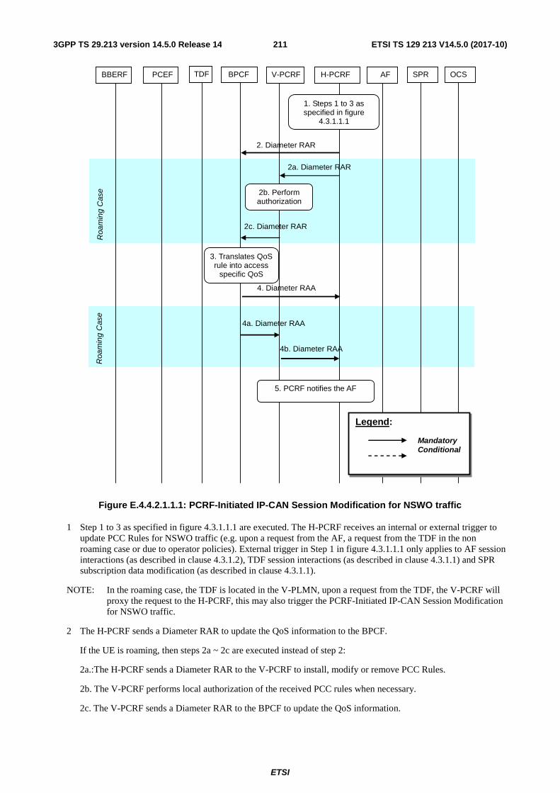
ETSI
ETSI TS 129 213 V14.5.0 (2017-10)2113GPP TS 29.213 version 14.5.0 Release 14
Roa
min
g C
ase
R
oam
ing
Cas
e
BBERF PCEF V-PCRF AF H-PCRF SPR
2. Diameter RAR
4. Diameter RAA
Legend:
Mandatory Conditional
TDF
1. Steps 1 to 3 as specified in figure
4.3.1.1.1
5. PCRF notifies the AF
OCS BPCF
3. Translates QoS rule into access
specific QoS
2a. Diameter RAR
2c. Diameter RAR
4a. Diameter RAA
4b. Diameter RAA
2b. Perform authorization
Figure E.4.4.2.1.1.1: PCRF-Initiated IP-CAN Session Modification for NSWO traffic
1 Step 1 to 3 as specified in figure 4.3.1.1.1 are executed. The H-PCRF receives an internal or external trigger to update PCC Rules for NSWO traffic (e.g. upon a request from the AF, a request from the TDF in the non roaming case or due to operator policies). External trigger in Step 1 in figure 4.3.1.1.1 only applies to AF session interactions (as described in clause 4.3.1.2), TDF session interactions (as described in clause 4.3.1.1) and SPR subscription data modification (as described in clause 4.3.1.1).
NOTE: In the roaming case, the TDF is located in the V-PLMN, upon a request from the TDF, the V-PCRF will proxy the request to the H-PCRF, this may also trigger the PCRF-Initiated IP-CAN Session Modification for NSWO traffic.
2 The H-PCRF sends a Diameter RAR to update the QoS information to the BPCF.
If the UE is roaming, then steps 2a ~ 2c are executed instead of step 2:
2a.:The H-PCRF sends a Diameter RAR to the V-PCRF to install, modify or remove PCC Rules.
2b. The V-PCRF performs local authorization of the received PCC rules when necessary.
2c. The V-PCRF sends a Diameter RAR to the BPCF to update the QoS information.
ETSI
ETSI TS 129 213 V14.5.0 (2017-10)2123GPP TS 29.213 version 14.5.0 Release 14
3 The BPCF shall perform QoS validation and translates the PCC rule as received (i.e. SDF template, QCI, MBR, GBR and ARP) into access specific QoS parameters applicable in the Fixed Broadband Access.
NOTE: The detail of the mapping from 3GPP QoS parameters on S9a to QoS parameters applicable in the Fixed Broadband Access is out of 3GPP scope.
4. The BPCF sends RAA to the H-PCRF to acknowledge the RAR and informs the H-PCRF about the outcome of the PCC rule operation. If the BPCF cannot provide the requested QoS from the PCRF, the BPCF may respond with the acceptable QoS.
If the UE is roaming, then steps 4a ~ 4b are executed instead of step 4:
4a. The BPCF sends RAA to the V-PCRF to acknowledge the RAR and informs the V-PCRF about the outcome of the PCC rule operation. If the BPCF cannot provide the QoS requested by the H-PCRF, the BPCF may respond with the acceptable QoS.
4b. The V-PCRF forwards the RAA to the H-PCRF to acknowledge the RAR and informs the H-PCRF about the outcome of the PCC rule operation.
NOTE: If the H-PCRF is informed that the BPCF cannot provide the requested QoS, the H-PCRF may decide to install, modify or remove PCC rules. In that case, the same flow as described in this clause will be executed.
5. If the AF requested it, the PCRF notifies the AF as described in steps 6-11 in clause 4.3.2.1.1.
E.4.4.2.2 BPCF-initiated IP-CAN Session Modification
This procedure is applicable for WLAN scenario.

ETSI
ETSI TS 129 213 V14.5.0 (2017-10)2133GPP TS 29.213 version 14.5.0 Release 14
Roa
min
g C
ase
Roa
min
g C
ase
BBERF PCEF V-PCRF AF H-PCRF SPR
2. Diameter CCR
3. Diameter CCA
Legend:
Mandatory Conditional
TDF
4. PCRF-initiated IP-CAN Session Modification as described in E.4.4.2.1
OCS BPCF
2c. Diameter CCR
2a. Diameter CCR
3b. Diameter CCA
3a. Diameter CCA
1. Trigger
2b. Store information
Figure E.4.4.2.2.1: BPCF-Initiated IP-CAN Session Modification for NSWO traffic
1. The trigger for this procedure is that the Fixed Broadband Access network has pre-empted some resources and wants to report a PCC rule failure to the PCRF, or when the Fixed Broadband Access network cannot sustain the bandwidth allocated to a particular traffic class/DSCP aggregate.
2. The BPCF sends a Diameter CCR to the H-PCRF with the CC-Request-Type AVP set to the value UPDATE_REQUEST to report PCC Rule failure.
When the UE is roaming, steps 2a ~ 2c are executed instead of step 2:
2a. The BPCF sends a Diameter CCR to the V-PCRF with the CC-Request-Type AVP set to the value UPDATE_REQUEST to report PCC Rule failure.
2b. The V-PCRF stores the information received.
2c. The V-PCRF sends a Diameter CCR to the H-PCRF within the information received in step 2a to report PCC Rule failure. The V-PCRF shall link the S9a* session to S9 session.
3 The H-PCRF sends a Diameter CCA to the BPCF to acknowledge the CCR command.
When the UE is roaming, steps 3a ~ 3b are executed instead of step 3:

ETSI
ETSI TS 129 213 V14.5.0 (2017-10)2143GPP TS 29.213 version 14.5.0 Release 14
3a. The H-PCRF sends a Diameter CCA to the BPCF to acknowledge the CCR command..
3b. The V-PCRF sends a Diameter CCA to the BPCF to acknowledge the CCR command.
4. The PCRF-initiated IP-CAN Session Modification as described in E.4.4.2.1 may take place.
E.5 3GPP HNB Procedures – CS Support
E.5.1 S9a CS Session Establishment In the following procedure, the PCRF is the V-PCRF for the roaming UE.
BPCF PCRFHNB GW
2.Diameter CCR
4.Diameter CCA
6.Diameter TEA
8.Diameter CCA
1. Trigger
7.Diameter CCR
5.Diameter TER
3. Store information
Figure E.5.1.1: S9a CS session Establishment
1. The HNB GW receives a trigger to establish an S15 session with the PCRF when the HNB performs the registration to the HNB GW.
2. The HNB GW initiates an S15 session with the PCRF by sending a CCR to the PCRF with the CC-Request-Type AVP set to the value INITIAL_REQUEST. The HNB GW provides the HNB Local IP address and the UDP source port number of IPSec tunnel if NA(P)T is detected.
3. The PCRF stores the information received in the CCR.
4. The PCRF acknowledges the session establishment by sending a CCA message.
5. The PCRF shall send a TER command to BPCF to trigger an S9a session establishment procedure. The PCRF provides HNB Local IP address and UDP source port number if available. The PCRF shall include the Auth-Session-State AVP set to NO_STATE_MAINTAINED.

ETSI
ETSI TS 129 213 V14.5.0 (2017-10)2153GPP TS 29.213 version 14.5.0 Release 14
NOTE: When the HNB performs the registration to the HNB GW, there is no PS service handled by the HNB. So there is no already established S9a session for the HNB.
6. The BPCF acknowledges the TER command by sending a TEA command.
7. The BPCF initiates an S9a session establishment with the PCRF by sending a CCR to the PCRF with the CC-Request-Type AVP set to the value INITIAL_REQUEST. The BPCF provides HNB local IP address and UDP source port number if available.
8. The PCRF acknowledges the S9a Session establishment by sending a CCA to the BPCF.
E.5.2 PCRF initiated S9a CS Session Modification In the following procedure, the PCRF is the V-PCRF for the roaming UE.
Figure E.5.2.1: S9a CS session Modification
This procedure is performed when the first UE or a subsequent UE connected to a HNB requesting a CS service.
1. The HNB GW receives RAB assignment message to request the resource for the CS service.
2. The HNB GW initiates an S15 session modification with the PCRF by sending a CCR to the PCRF with the CC-Request-Type AVP set to the value UPDATE_REQUEST. The HNB GW provides QoS information derived from the RAB assignment message by the HNB GW.
3. The PCRF initiates an S9a session modification procedure to the BPCF by sending a RAR to the BPCF. The PCRF provides QoS rule generated by the PCRF based on the QoS information received in step 2.
4. Fixed Broadband access network performs the admission control based on the QoS rule received in step3 and responds with the outcome of the admission control by sending a RAA to the PCRF.
5. The PCRF responds with outcome of the admission control to the HNB GW by sending a CCA.
6. The HNB GW complete the procedure for the CS service.

ETSI
ETSI TS 129 213 V14.5.0 (2017-10)2163GPP TS 29.213 version 14.5.0 Release 14
E.5.2a BPCF initiated S9a CS Session Modification In the following procedure, the PCRF is the V-PCRF for the roaming UE.
Figure E.5.2a.1: S9a CS session Modification
This procedure is performed when the first UE or a subsequent UE is connected to a HNB requesting a CS service.
1. The BPCF receives the report of the QoS rule failure
2. The BPCF initiates an S9a session modification with the PCRF by sending a CCR to the PCRF with the CC-Request-Type AVP set to the value UPDATE_REQUEST. The BPCF includes QoS-Rule-Report AVP to identify the QoS rules that failed and PCC-Rule-Status AVP set to the value “INACTIVE”.
3. The PCRF acknowledges to the BPCF by sending a CCA.
4. The PCRF initiates the S15 session modification procedure by sending a RAR command to the HNB GW and includes the information as defined in clause E.5.3.2.2 of 3GPP TS 29.212 [9].
5. The HNB GW acknowledges to the PCRF by sending a RAA.
6. The HNB GW completes the procedure for the CS service.
E.5.3 S9a CS Session Termination In the following procedure, the PCRF is the V-PCRF for the roaming UE.

ETSI
ETSI TS 129 213 V14.5.0 (2017-10)2173GPP TS 29.213 version 14.5.0 Release 14
BPCF PCRFHNB GW
2.Diameter CCR
3.Diameter CCA
5.Diameter RAA
1. Trigger
4.Diameter RAR
7.Diameter CCA
6.Diameter CCR
Figure E.5.3.1: S9a CS Session Termination
1. The HNB GW initiates deregistration for the HNB or receives a deregistration request from the HNB.
2. The HNB GW initiates an S15 session termination with the PCRF by sending a CCR to the PCRF with the CC-Request-Type AVP set to the value TERMINATION _REQUEST.
3. The PCRF acknowledges the session termination by sending a Diameter CCA message to HNB GW.
4. The PCRF sends a Diameter RAR message to the BPCF including a Session-Release-Cause AVP to indicate request for terminating the S9a session.
NOTE: When the HNB is deregistered, there is no PS service which can be handled by the HNB any more. So S9a session for the HNB can be terminated.
5. The BPCF acknowledges the S9a session termination request by sending a Diameter RAA message.
6. The BPCF initiates the S9a session termination with the PCRF by sending a CCR to the PCRF with the CC-Request-Type AVP set to the value TERMINATION _REQUEST.
7. The PCRF acknowledges the session termination by sending a Diameter CCA message to BPCF.
E.6 PCRF Addressing
E.6.1 General PCRF discovery at the DRA shall be done according to clause 7.1 with the additions described in this clause.
For EPC-routed scenario, the DRA keeps status of the assigned PCRF for a certain UE for the applicable reference points, i.e. Gx, Gxx, Rx, Sd (Unsolicited application reporting), S9a and S9 (for roaming cases).

ETSI
ETSI TS 129 213 V14.5.0 (2017-10)2183GPP TS 29.213 version 14.5.0 Release 14
For NSWO scenario, the DRA keeps status of the assigned PCRF for a certain UE for the applicable references points, i.e. Rx, Sd (Unsolicited application reporting) and S9a.The H-DRA keeps status of the assigned H-PCRF for a certain UE for Rx and S9 reference points. The V-DRA keeps the status of the assigned V-PCRF for a certain UE for the S9a and Sd (Unsolicited application reporting) reference points.
The BPCF, as a Diameter client of the DRA, shall support all procedures required to properly interoperate with the DRA in both the proxy and redirect modes.
E.6.2 DRA Definition For the EPC-routed scenario, DRA is defined as specified in clause 7.2 with the additions described in this clause.
The DRA is a functional element that ensures that all Diameter sessions established over the Gx, S9, Gxx, Rx, S9a and for unsolicited application reporting, the Sd reference points for a certain IP-CAN session reach the same PCRF when multiple and separately addressable PCRFs have been deployed in a Diameter realm.
For the NSWO scenario, the DRA shall ensure that all Diameter sessions established over the Rx, S9a and for unsolicited application reporting, the Sd reference points for a certain UE reach the same PCRF. The H-DRA shall ensure that all Diameter sessions established over Rx and S9 reference points for a certain UE reach the same PCRF. The V-DRA shall ensure that all Diameter sessions established over S9a and for unsolicited application reporting, the Sd reference points for a certain UE reach the same V-PCRF.
E.6.3 DRA Procedure
E.6.3.1 DRA Information Storage
For EPC-routed traffic, DRA Information Storage shall be done according to clause 7.3.1 with the additions described in this subclause. The V-PCRF routing information (i.e. DRA binding) in the V-DRA is created when the S9 session establishment trigger is received.
The V-PCRF routing information stored in the V-DRA shall be removed when the S9 session termination notification is received.
The DRA has information about the user identity (UE NAI), the UE Local IP address/H(e)NB Local IP address, the PDN Id (if available) and the selected PCRF identity for a certain IP-CAN Session or a certain user.
For NSWO traffic, the DRA Information Storage shall be done as specified below:
- The DRA shall maintain PCRF routing information per UE-NAI and APN.
- The DRA has information about the user identity (UE NAI), the local UE Ipv4 address and/or the local UE Ipv6 address/prefix, the APN (i.e. NSWO_APN) and the selected PCRF identity for a certain UE.
- The PCRF routing information stored for an S9a* session in the DRA shall be removed after the S9a* session is terminated.
When both EPC-routed and NSWO traffic exist, the DRA Information Storage shall be done as specified below:
- The DRA shall maintain PCRF routing information per UE-NAI or per UE-NAI and APN.
- The DRA has information received for both EPC-Routed and NSWO scenarios and the selected PCRF identity per UE-NAI or per UE-NAI and APN.
- The PCRF routing information stored per UE in the DRA shall be removed when no more S9a sessions and S9a* sessions are active for the UE.
E.6.3.2 Capabilities Exchange
For EPC-routed traffic, capabilities exchange shall be done according to clause 7.3.2.
For NSWO traffic, the Redirect DRA and Proxy DRA shall advertise the support of S9a*, Rx and Sd (for unsolicited application reporting) applications according to clause 7.3.3.

ETSI
ETSI TS 129 213 V14.5.0 (2017-10)2193GPP TS 29.213 version 14.5.0 Release 14
E.6.3.3 Redirect DRA
Redirect DRA is specified in clause 7.3.4 with the additions described in this subclause.
For EPC-routed traffic, for case 1 (home routed case), the V-DRA shall behave as follows:
- If the request is an S9 session establishment trigger from the H-PCRF, it shall select a V-PCRF to handle the S9 session for that UE. It shall then send the redirect message including selected V-PCRF to the H-PCRF.
- If the request is an S9 session termination notification from H-PCRF, the V-DRA shall remove the PCRF routing information (i.e. DRA binding). If the V-DRA does not have a V-PCRF already selected, it shall reject the request.
The S9 session establishment trigger and the S9 session termination notification request shall have the same information of user identity (UE NAI), the UE Local IP address/H(e)NB Local IP address, the PDN Id(if available). The DRA shall remove the DRA binding based on the above information when the DRA receives the S9 session termination notification (i.e. a TER command including DRA- Binding AVP set to the value DRA_BINDING_DELETION).
For NSWO traffic, the DRA is maintaining PCRF routing information per UE-NAI and APN. The DRA shall be aware of the S9a* Diameter termination request as defined in 3GPP TS 29.215 [22] in order to release the DRA binding information.
E.6.3.4 Proxy DRA
Proxy DRA is specified in clause 7.3.5 with the additions described in this subclause.
For EPC-routed traffic for case 1 (home routed case), when the V-DRA receives a message from the H-PCRF, it shall behave as follows:
- If the message is an S9 session establishment trigger from the H-PCRF, it shall select a V-PCRF to handle the S9 session for that UE. It shall then proxy the request to the selected V-PCRF. The V-DRA indicates that there is a V-DRA deployed in the visited PLMN by including the DRA-Deployment AVP in TEA command.
- If the message is an S9 session termination notification from the H-PCRF, the V-DRA shall remove the PCRF routing information (i.e. DRA binding). If the V-DRA does not have a V-PCRF already selected, it shall reject the request.
The S9 session establishment trigger and the S9 session termination notification shall have the same information of user identity (UE NAI), the UE Local IP address/H(e)NB Local IP address and the PDN Id (if available). The DRA shall remove the DRA binding based on the above information when the DRA receives the S9 session termination notification (i.e. a TER command including DRA-Binding AVP set to the value DRA_BINDING_DELETION).
Proxy DRA is specified in clause 7.3.5 with the additions described in this subclause.
For NSWO traffic in both non-roaming and roaming cases, when the (V-) DRA receives an S9a* request from the BPCF, it shall behave as follows:
- If the request is an S9a* session establishment, it shall select a V-PCRF to handle the S9 session for that UE and APN. It shall then proxy the request to the selected V-PCRF.
- If the request is an S9a* session termination, the (V-) DRA shall remove the PCRF routing information and proxy the request to the (V-) PCRF. If the (V-) DRA does not have a (V-) PCRF already selected, it shall reject the request.
- If the request is an S9a* session modification, the (V-) DRA shall proxy the request.
The BPCF shall be capable of sending every message of a session to the DRA. The BPCF may be configured to bypass the (V-) DRA on S9a* session modification messages by sending these types of messages directly to the (V-) PCRF.
E.6.3.5 PCRF selection by BPCF
For EPC-routed traffic, when the S9a Session Establishment request is triggered by the (V-) PCRF, the BPCF may use the (V-) PCRF identity provided within the PCRF-Address AVP in the S9a Session Establishment Trigger.

ETSI
ETSI TS 129 213 V14.5.0 (2017-10)2203GPP TS 29.213 version 14.5.0 Release 14
The BPCF may also use the DRA procedures as described in clause 7.3. In order to do so, the BPCF shall provide the DRA of the PCRF realm with identity parameters during the S9a Session Establishment procedure. The identity parameters from the BPCF may comprise the UE Local Ipv4 or UE local Ipv6 address in the UE-Local-IP-Address AVP (WLAN scenario), H(e)NB Local IP address in the HeNB-Local-IP-Address AVP (H(e)NB scenario), PDN information in the Called-Station-Id AVP if available and user identity in the Subscription-Id AVP. The BPCF obtains these data from the S9a Session Establishment Trigger procedure initiated by the (V-) PCRF.
For NSWO traffic, the BPCF finds the PCRF using the DRA procedures as described in clause 7.3. In order to do so, the BPCF shall provide the DRA of the PCRF realm with identity parameters during the S9a* Session Establishment procedure. The identity parameters from the BPCF shall comprise the UE local Ipv4 adress or UE local Ipv6 prefix/address in the UE-Local-IP-Address AVP or UE-Local-IP-Prefix AVP, the APN in the Called-Station-Id AVP and user identity in the Subscription-Id AVP.
For both EPC-routed traffic and NSWO traffic, if the redirect agent is used for DRA, the DRA shall use the redirecting requests procedure as specified in IETF RFC 6733 [61], and include the PCRF identity in the Redirect-Host AVP in the Diameter reply sent to the BPCF .
If proxy agent is used for DRA, the DRA should use the proxy procedure as specified in IETF RFC 6733 [61]. For PA2 solution (described in clause 7.1) only S9a/S9a* session establishment and S9a/S9a* session termination messages shall be sent through the DRA.
For NSWO traffic in a roaming scenario the selected V-PCRF shall belong to the same VPLMN selected during the 3GPP –based authentication procedure. The BPCF uses the VPLMN-Id to find the V-DRA in the VPLMN. The V-PCRF finds the DRA in the HPLMN according to clause 7.3.8.
NOTE: The BPCF will use the VPLMN-Id to obtain the Destination-Realm AVP used to find the V-DRA and then to find the V-PCRF using Diameter based procedures as described in IETF RFC 6733 [61].
E.6.3.6 PCRF selection by AF and TDF in Unsolicited application reporting mode for NSWO traffic
PCRF selection by the AF shall be done according to clause 7.3.7.
PCRF selection by the TDF shall be done according to clause 7.3.9.
NOTE: The DRA matches the received UE IP address received in either the Framed-IP-Address AVP or the Framed-Ipv6-Prefix AVP in the Rx and Sd reference point with the UE Local IP Address received in UE-Local-IP-Address AVP or UE Local Ipv6 Prefix in the UE-Local-IP-Prefix AVP in the S9a reference point in order to select the same PCRF.
E.6.3.7 PCRF selection in a roaming scenario
For both EPC-routed traffic and NSWO traffic, the V-PCRF uses the DRA procedures as described in clause 7.3.8 to address the H-PCRF. In order to do so, the V-PCRF shall provide the DRA of the H-PCRF realm with identity parameters during the S9 Session Establishment procedure.
For EPC-routed traffic, the identity parameters from the V-PCRF may comprise the UE Local Ipv4 or UE local Ipv6 address in the UE-Local-IP-Address AVP (WLAN scenario), H(e)NB Local IP address in the HeNB-Local-IP-Address AVP (H(e)NB scenario), PDN information in the Called-Station-Id AVP if available and user identity in the Subscription-Id AVP obtained from the S9 Session Establishment Trigger procedure initiated by the H-PCRF.
For NSWO traffic, the identity parameters from the V-PCRF may comprise the UE Local Ipv4 or Ipv6 address in the UE-Local-IP-Address AVP or UE local Ipv6 prefix in the UE-Local-IP-Prefix AVP, PDN information in the Called-Station-Id AVP and user identity in the Subscription-Id AVP obtained from the S9a* Session Establishment procedure.
E.6.3.8 PCRF selection for the HNB CS Service
When the DRA receives a request for a certain S15 Session establishment from the HNB GW, the DRA selects a suitable PCRF for the S15 Session based on the HNB local IP address within the HeNB-Local-IP-Address AVP. When the S15 Session is terminated, the DRA shall remove the information about the S15 Session.

ETSI
ETSI TS 129 213 V14.5.0 (2017-10)2213GPP TS 29.213 version 14.5.0 Release 14
E.6.4 DRA flows
E.6.4.1 General
For the EPC-routed traffic case and for the non-roaming case, the flows for the non-roaming case in the clauses 7.4.1 and 7.4.2 are applied with the following exception:
- BPCF acts as a client and messages are S9a Diameter messages;
- The external trigger in the Establishment of Diameter Sessions is an S9a session establishment trigger message from the PCRF
For the EPC-routed traffic case and for the roaming case, the flows for the roaming case in clauses 7.4.1 and 7.4.2 are applied with the following exception:
- The external trigger in the Establishment of Diameter Sessions is an S9 session establishment trigger message from the PCRF for case 1 and home routed case.
The flows in clauses E.6.4.2 and E.6.4.3 are applicable to the EPC-routed traffic and for case 1 and UE roaming in the home routed scenario.
For the NSWO traffic case and for the non-roaming case, the flows for the non-roaming and roaming case in the clauses 7.4.1 and 7.4.2 are applied with following exception:
- BPCF acts as a client and messages are S9a* Diameter messages for the non-roaming case.
E.6.4.2 Proxy DRA
E.6.4.2.1 S9 session establishment trigger
1. External trigger
V-PCRF-1 H-PCRF
2. TER
4. Proxy TER
3. DRA binding creation
5. TEA
V-DRA (proxy)
V-PCRF-2
6. Proxy TEA
Figure E.6.4.2.1.1: S9 session establishment trigger using DRA (proxy) – Roaming case
1. The H-PCRF receives an external trigger (e.g. IP-CAN session establishment request) and determines that an S9 session shall be established.
2. A TER command including user identity, PDN ID if available, UE Local IP address/H(e)NB Local IP address and UDP source port number(if NA(P)T is detected) is sent by the H-PCRF and received by a V-DRA (proxy) in

ETSI
ETSI TS 129 213 V14.5.0 (2017-10)2223GPP TS 29.213 version 14.5.0 Release 14
the visited PLMN. The Auth-Session-State AVP set to NO_STATE_MAINTAINED shall be included in the TER.
3. The V-DRA (proxy) stores the user identity and creates a dynamic DRA binding for this user. (assignment of a PCRF node per UE).
4. The V-DRA (proxy) proxies the TER to the target PCRF in the visited PLMN.
5. V-PCRF-1 returns a TEA to the V-DRA (proxy).
6. V-DRA (proxy) proxies the TEA to the H-PCRF and indicates there is a DRA deployed in the visited PLMN by including the DRA-Deployment AVP in the TEA.
NOTE: The H-PCRF is aware that there is a V-DRA (proxy) deployed in the network at this stage.
E.6.4.2.2 S9 session termination notification
V-PCRF-1 H-PCRF
2. TER
3. DRA binding verification and release
V-DRA (proxy)
V-PCRF-2
4. TEA
1. H-PCRF initiated S9 session termination
Figure E.6.4.2.2.1: S9 session termination notification using V-DRA (proxy) – Roaming cases
1. The H-PCRF receives an external trigger (e.g.IP-CAN session termination request from the BBERF or the PCEF) and initiates S9 session termination procedure.
2. If the V-DRA is deployed in the VPLMN as indicated in step 6 of clause E.6.4.2.1, a TER command including DRA-Binding AVP set to the value DRA_BINDING_DELETION is sent by the H-PCRF and received by the V-DRA (proxy) in the visited PLMN. The message includes the same user identity as the S9 session establishment trigger message.
3. The V-DRA (proxy) verifies that there is an active DRA binding for the user based on the user identity in the request and removes the DRA binding.
4. V-DRA (proxy) returns the TEA to the H-PCRF.

ETSI
ETSI TS 129 213 V14.5.0 (2017-10)2233GPP TS 29.213 version 14.5.0 Release 14
E.6.4.3 Redirect DRA
E.6.4.3.1 S9 session establishment trigger
1. External trigger
V-PCRF-1 H-PCRF
2. TER
4. TEA(redirect)
3. DRA binding creation
5. TER
V-DRA (Redirect)
V-PCRF-2
6. TEA
Figure E.6.4.3.1.1: S9 session establishment trigger using DRA (Redirect) – Roaming case
1. The H-PCRF receives an external trigger (e.g. IP-CAN session establishment request) and determines that an S9 session shall be established.
2. A TER command including user identity, PDN ID if available, UE Local IP address/H(e)NB Local IP address, UDP source port number(if NA(P)T is detected) and the FQDN of Fixed Broadband network where the H(e)NB is connected to if available is sent by the H-PCRF and received by a V-DRA (proxy) in the visited PLMN. The Auth-Session-State AVP set to NO_STATE_MAINTAINED shall be included in the TER.
3. The V-DRA (redirect) stores the user identity and creates a dynamic DRA binding for this user. (assignment of a PCRF node per UE).
4. The V-DRA (redirect) sends a TEA command indicating redirection as defined in IETF RFC 6733 [61]. The target V-PCRF identity is included in the Redirect-Host AVP.
NOTE: The H-PCRF is aware that there is a V-DRA (redirect) deployed in the network at this stage.
5. The H-PCRF re-sends the TER command of step 2 to the target V-PCRF-1.
6. The V-PCRF-1 returns a TEA 223vailab.
E.6.4.3.2 S9 session termination notification
The detailed procedure is the same as the S9 session termination notification using DRA (Proxy), which is described in clause E.6.4.2.2.
If the H-PCRF was aware that there is a V-DRA deployed in the V-PLMN (step 4 of S9 session establishment procedure according to clause E.6.4.3.1), this procedure shall apply.

ETSI
ETSI TS 129 213 V14.5.0 (2017-10)2243GPP TS 29.213 version 14.5.0 Release 14
E.7 BPCF Addressing
E.7.1 General For S9a session establishment trigger procedure initiated by the (V-)PCRF, the PCRF (for non-roaming case) and the V-PCRF (for roaming case) is configured with IP address range mappings { (Ipx..Ipy) -> BBF network entry point}. The PCRF (for non-roaming) and the V-PCRF (for roaming cases) selects the correct BBF network entry point based on UE Local IP address for WLAN scenario and based on H(e)NB IP address and FQDN if available for H(e)NB case received from the PCEF/BBERF/HNB GW for H(e)NB scenario. The implementation of a BBF network entry point is out-of-scope for 3GPP e.g. be a BPCF or a DRA.
For case 1 and roaming with home routed, for S9 session establishment trigger procedure initiated by the H-PCRF, H-PCRF finds the VPLMN according to the PLMN Id of the visited network in 3GPP-SGSN-MCC-MNC AVP if received at IP-CAN session establishment received over Gx reference point, and then discovers V-PCRF by V-DRA if there are more than one PCRF deployed in the visited network. The H-PCRF sends the H(e)NB Local IP address within HeNB-Local-IP-Address AVP and optionally the FQDN of BBF access network within the HeNB-BBF-FQDN AVP for H(e)NB scenario or the UE local IP address within the UE-Local-IP-Address AVP for WLAN scenario to the V-PCRF over the S9 reference point.
E.8 Session Linking Function PCRF and BPCF needs to support session linking function. The PCRF shall be able to perform the linking between multiple Gx and Gateway Control Session to the same S9a session.
When receiving an IP-CAN Session Establishment request or an IP-CAN Session modification request with an UE local IP address or H(e)NB local IP address, the PCRF shall perform the session linking between the S9a session and the corresponding Gx session according to the UE Local IP address/ H(e)NB local IP address.
When receiving a Gateway Control Session Establishment Request or a Gateway Control and QoS Rule Request with UE local IP Address or a H(e)NB local IP Address change, the PCRF shall perform the session linking between the S9a session and the Gateway Control Session according to the UE Local IP address/ H(e)NB local IP address.
If there is not an established S9a session which could be linked to the Gx or Gateway Control Session, the PCRF shall initiate the S9a Session Establishment trigger procedure.
For 3GPP HNB Procedures with CS support, the PCRF shall be able to perform the linking between S15 sessions and the S9a session.
NOTE 1: There is a single S15 session per HNB for CS calls for all Ues connected to the HNB in order to improve performance. In addition, for CS calls there are no UE specific policies and therefore a single PCRF can handle CS calls for all Ues.

ETSI
ETSI TS 129 213 V14.5.0 (2017-10)2253GPP TS 29.213 version 14.5.0 Release 14
Annex F (normative): Access specific aspects, Fixed Broadband Access network convergence
F.1 General This annex defines the enhancement to PCC framework for supporting policy and charging control in the fixed broadband access network in the convergent scenario where the PCRF controls directly the network element(s) in the fixed broadband access without the mediation of a different policy server, such as the Broadband Policy Control Function (BPCF).
Policy and charging control is provided for both Non-seamless WLAN offload traffic from a 3GPP UE and the traffic from fixed devices.
F.2 Definitions and abbreviations
F.2.1 Definitions The definitions in the following are relevant for this Annex only.
UE local IP address is defined as either the public IP address assigned to the UE by the Broadband Forum domain in the no-NAT case, or the public IP address assigned by the Broadband Forum domain to the NATed RG.
IP-CAN session as defined in clause 3.1 applies with the following clarifications for fixed broadband access. The term UE corresponds to the device that accesses the services provided by the network (i.e. either RG, or 3GPP UE or fixed end-device), the PDN identifies the IP network where the device gets IP connectivity and the UE identity information may be the IMSI, the user-name or the access line identifier (if available). In a Fixed Broadband Access an IP-CAN session corresponds to a Subscriber IP Session defined in Broadband Forum TR-146.
NOTE: The PDN connection concept and APN are not applicable to a Subscriber IP session for a fixed device.
F.2.2 Abbreviations
The following abbreviations are relevant for this annex only:
BBF Broadband Forum BPCF Broadband Policy Control Function NSWO Non-Seamless WLAN offload NSWO-APN Non-Seamless WLAN offload APN RG Residential Gateway
F.3 Binding Mechanisms
F.3.1 NSWO traffic The binding mechanism in clause 5 applies, except that the QoS rule generation as described in clause 5.4 and the bearer binding as described in clause 5.4 do not apply since the Fixed Broadband Access network does not support the concept of a bearer and multiple bearers as defined in 3GPP network.
The following exceptions or modifications in PCC rule authorization also apply:
- The PCRF does not authorize traffic mapping information from the UE.

ETSI
ETSI TS 129 213 V14.5.0 (2017-10)2263GPP TS 29.213 version 14.5.0 Release 14
- The PCEF in the IP Edge would map the received QoS information over Gx into the relevant data as specified in Broadband Forum.
- MPS and emergency services are not supported.
- BCM concept is not applied.
F.3.2 Traffic from fixed devices The binding mechanism as described in Annex F.3.1 applies to the scenario of traffic from fixed devices with the following exceptions or modifications:
- S9 reference point is not applicable.
- The Subscriber Identifier used by fixed device at establishment of Subscriber IP session in Fixed Broadband Access network can be the Access Line Identifier (Physical-Access-ID AVP and Logical-Access-ID AVP) or the username (Subscription-Id AVP), for example when the Subscriber IP session is a PPP Session.
NOTE: In case the Subscriber Identifier in the IP-CAN and the application level identity for the fixed device are of different kinds, the PCRF needs to map between them. Such mapping is not subject to specification within this TS.
F.4 PCC procedures
F.4.1 Introduction The PCC procedures specified in clause 4.1, 4.2 and 4.3 apply to the Fixed Broadband Access network convergence with the following exceptions or restrictions:
- Roaming scenarios are not applicable to fixed devices and RGs.
- Gxx reference point is not used.
- UE requested bearer resource initiation, modification or termination procedure is not supported.
- Bearer procedures are not supported in the fixed network.
- Bearer Control Mode (BCM) concept does not apply.
- Authorized QoS per bearer and authorized MBR per QCI are not applicable
- MPS Services and IMS Emergency Services are not supported.
F.4.2 IP-CAN Session Establishment The PCEF in the IP Edge initiates the IP-CAN session establishment as specified in clause 4.1, with the exceptions as described in Annex F.4.1.The PCRF shall provide parameters to the PCEF in the IP Edge at IP-CAN session establishment as described in 3GPP TS 29.212 [9] Annex G.5.2.
F.4.3 IP-CAN Session Termination
F.4.3.1 UE-Initiated
UE-initiated IP-CAN session termination is not applicable to convergent scenario.

ETSI
ETSI TS 129 213 V14.5.0 (2017-10)2273GPP TS 29.213 version 14.5.0 Release 14
F.4.3.2 PCEF-Initiated
For PCEF-Initiated IP-CAN session termination the procedures described in clause 4.2.2 apply, with the exceptions described in clause F.4.1.
F.4.3.3 PCRF-Initiated
For PCRF-Initiated IP-CAN session termination the procedures described in clause 4.2.3 apply, with the exceptions described in clause F.4.1.
F.4.4 IP-CAN Session Modification
F.4.4.1 PCRF-Initiated IP-CAN Session Modification
For PCRF-Initiated IP-CAN session modification, the procedures described in clause 4.3.1 apply, with the exceptions described in clause F.4.1. The PCRF shall provide parameters to the PCEF in the IP Edge at IP-CAN session modification as described in 3GPP TS 29.212 [9] Annex G.5.4.2.
F.4.4.2 PCEF-Initiated IP-CAN Session Modification
For PCEF-Initiated IP-CAN session modification, the procedures described in clause 4.3.2 apply, with the exceptions described in clause F.4.1. The PCRF shall provide parameters to the PCEF in the IP Edge at IP-CAN session modification as described in 3GPP TS 29.212 [9] Annex G.5.4.1.
F.5 PCRF Addressing
F.5.1 General PCRF discovery and selection shall be done according to clause 7.1 with the modifications or exceptions described in this subclause.
- Gxx reference point is not used.
- The Subscriber Identifier specified in 3GPP TS 23.203 [2] clause S.5.1.2 is used as user identity.
- For a 3GPP UE, the NSWO-APN is also available.
- The IPv6 address within the Framed-IPv6-Prefix may be included in the CCR command in the case of bridge-mode RG.
F.5.2 DRA Definition The DRA definition in clause 7.2 applies with the modifications or exceptions as described in Annex F.5.1.
F.5.3 DRA Procedure
F.5.3.1 Redirect DRA
Redirect DRA is specified in clause 7.3.4 with the adaptions listed in F.5.1.
F.5.3.2 Proxy DRA
Proxy DRA is specified in clause 7.3.5 with the adaptions listed in F.5.1.

ETSI
ETSI TS 129 213 V14.5.0 (2017-10)2283GPP TS 29.213 version 14.5.0 Release 14
F.5.3.3 PCRF selection by AF and TDF in unsolicited application reporting mode
PCRF selection by the AF shall be done according to clause 7.3.7 with the modifications or exceptions as described in Annex F.5.1. PCRF selection by the TDF shall be done according to clause 7.3.9 with the modifications or exceptions as described in Annex F.5.1.
F.5.3.4 PCRF selection in a roaming scenario
The procedures as described in clause 7.3.8 for the V-PCRF to select the H-PCRF apply with the modifications or exceptions as described in Annex F.5.1.
F.5.4 DRA flows The DRA procedures specified in clause 7.4.1 and 7.4.2 apply to the Fixed Broadband Access network convergence with the following exceptions or restrictions:
- Gxx reference point is not used.
- Roaming scenarios are not applicable to fixed devices and RGs.

ETSI
ETSI TS 129 213 V14.5.0 (2017-10)2293GPP TS 29.213 version 14.5.0 Release 14
Annex G (normative): Diameter overload control mechanism
G.1 General Support for Diameter overload control by PCC functional elements is optional. Unless otherwise stated, the procedures defined in this Annex assume that a PCC functional element supports the Diameter overload control mechanism.
IETF RFC 7683 [33] specifies the Diameter overload control mechanism. This includes the definition of Diameter overload related AVPs and the Diameter overload related behavior.
To indicate support of the Diameter overload control mechanism, each PCC functional element shall include the OC-Supported-Features AVP in every Diameter request and answer as defined in IETF RFC 7683 [33].
Each PCC functional element (e.g. PCRF, PCEF, AF, etc) shall act asa reacting node and asa reporting node as defined in IETF RFC 7683 [33].
G.2 Reporting Node When a PCC functional element determines the need to request a reduction in the traffic it is handling due to an overload condition, it shall include the OC-OLR AVP in answer messages, as defined in IETF RFC 7683 [33].
How it determines that it is in an overload situation and the severity of the overload is implementation dependent and based on operator policy.
How it determines the specific contents of the OC-OLR AVP is implementation dependent and based on operator policy.
G.3 Reacting Node A PCC functional element acting as a reacting node applies the requested traffic reduction received in OC-OLR AVPs in answer messages to corresponding applicable requests, as per IETF RFC 7683 [33].
How it achieves the requested traffic reduction is implementation dependent.
Diameter requests related to priority traffic (e.g. MPS) as described in 3GPP TS 22.153 [58] and emergency have the highest priority. If required by the regional/national regulatory and operator policies, and when the reacting node is able to detect priority traffic, priority traffic shall be exempted from throttling due to Diameter overload control up to the point where requested traffic reduction cannot be achieved without throttling the priority traffic. Relative priority amongst various priority traffic (e.g. MPS) and emergency traffic is subject to regional/national regulatory and operator policies.
G.4 DRA Diameter Overload Behavior The DRA may optionally incorporate agent behavior specified in IETF RFC 7683 [33].
G.4.1 DRA reacting to Host Reports The procedures defined in this clause are only applicable to the proxy DRA (PA1 and PA2) as the redirect DRA is not in the path of application answers and as such does not have access to overload reports from other nodes.
The proxy DRA shall use host reports as one of the inputs when making routing decisions for realm-routed requests, i.e. requests that do not contain a Destination-Host AVP. This is needed because entities sending such requests are not aware of the final recipient of the request (e.g. specific PCRF instance).
ETSI
ETSI TS 129 213 V14.5.0 (2017-10)2303GPP TS 29.213 version 14.5.0 Release 14
The following scenarios shall be addressed:
- No binding exists for the request and the request can result in a new binding (e.g. IP-CAN session establishment); in this case the DRA is selecting the PCRF that will handle the binding. The DRA should use any active and relevant Diameter overload host reports as one of the inputs to the selection of the PCRF. If all PCRFs are in an overload state, the DRA should reduce traffic sent to each of the PCRFs based on the individual host requested traffic reduction. This may result in the DRA rejecting the request.
- A binding already exists for the request – In this case the DRA should reduce the traffic sent to the overloaded node by the host requested traffic reduction. This may result in the DRA rejecting the request.
NOTE: Result-Code when rejecting a request in the above cases need to be used according to the IETF RFC 7683.
How the DRA achieves any requested traffic reduction is implementation dependent and/or based on operator policy.

ETSI
ETSI TS 129 213 V14.5.0 (2017-10)2313GPP TS 29.213 version 14.5.0 Release 14
Annex H (normative): Access specific procedures for 3GPP EPS
H.1 General The present annex defines IP-CAN specific requirements for 3GPP Evolved Packet System (EPS).
H.2 Binding Mechanisms The procedures defined in clause 5.4 apply.
Whenever the PCRF modifies the Authorized QoS of the default bearer, the BBF shall re-evaluate the bearer binding taking into account the default bearer QoS change the default bearer binding indication in the PCC Rule if applicable and any PCC Rule/QoS Rule operation requested by the PCRF.

ETSI
ETSI TS 129 213 V14.5.0 (2017-10)2323GPP TS 29.213 version 14.5.0 Release 14
Annex I (normative): APN matching procedures A PCRF or DRA needs to compare APN information received over different interfaces, for instance within the Called-Station-Id AVP, for certain purposes such as session binding. To do so, the PCRF or DRA shall apply the procedures in the present Annex.
The PCRF or DRA shall consider the different possible encoding formats of the APN defined in 3GPP TS 23.003 [37], clause 9.1. When the PCRF or DRA needs to compare an APN only containing the APN Network Identifier, with an APN containing both APN Network Identifier and APN Operator Identifier, the PCRF shall consider those APNs as matching if their APN Network Identifiers match. The PCRF shall perform a case-insensitive comparison for APN Network Identifiers and APN Operator Identifiers.

ETSI
ETSI TS 129 213 V14.5.0 (2017-10)2333GPP TS 29.213 version 14.5.0 Release 14
Annex J (normative): Diameter message priority mechanism
J.1 General The support of the Diameter message priority mechanism by PCC functional elements is optional. PCC functional elements that support Diameter message priority mechanism shall comply with the procedures specified in this annex.
IETF RFC 7944 [40] specifies the Diameter message priority mechanism that allows Diameter nodes to indicate the relative priority of Diameter messages. With this information, other Diameter nodes can leverage the relative priority of Diameter messages into routing, resource allocation, set the DSCP marking for transport of the associated Diameter message, and also abatement decisions when overload control is applied. This includes the definition of Diameter message priority related AVPs and the Diameter message priority related behaviour.
J.2 PCC functional element behaviour A PCC functional entity supporting the Diameter message priority mechanism shall comply with IETF RFC 7944 [40].
A PCC functional element sending a request shall determine the required priority according to its policies. When priority is required, the PCC functional element shall include the DRMP AVP indicating the required priority level in the request it sends, and shall prioritise the request according to the required priority level
When the PCC functional element receives the corresponding response, it shall prioritise the received response according to the priority level received within the DRMP AVP if present in the response, otherwise according to the priority level of the corresponding request.
When a PCC functional element receives a request, it shall handle the request according to the received DRMP AVP priority level. For the response, it may modify the priority level received in the DRMP AVP according to its policies and shall handle the response according to the required priority level. If the required priority level is different from the priority level received in the request, it shall include the DRMP AVP in the response.
If:
- a PCC functional element supports using the Diameter message priority mechanism for DSCP marking purposes,
- the transport network utilizes DSCP marking, and
- message-dependant DSCP marking is possible for the protocol stack transporting Diameter,
then the PCC functional element shall set the DSCP marking for transport of the request or response according to the required priority level.
The PCC functional element decisions for a required priority and the priority level value are implementation specific.
Diameter requests related to high priority traffic (e.g. MPS, emergency) shall contain a DRMP AVP with a high priority of which the level is operator dependent.
J.3 Interactions If the PCC entity supporting the Diameter message priority mechanism receives the request message containing both the Reservation-Priority AVP and DRMP AVP, the PCC entity shall prioritise the request according to priority level received within the DRMP AVP. This procedure also applies for MPS.
NOTE: Upon receipt of the request message containing the DRMP AVP, the PCRF will use the DRMP AVP to prioritize other PCC interfaces related to that IP-CAN session.

ETSI
ETSI TS 129 213 V14.5.0 (2017-10)2343GPP TS 29.213 version 14.5.0 Release 14
Annex K (normative): Diameter load control mechanism
K.1 General IETF draft-ietf-dime-load [60] specifies the Diameter load control mechanism. This includes the definition of Diameter Load AVP and the Diameter load related behaviour.
Whether Diameter load control mechanism is applicable for a specific interface is specified in the 3GPP specification for that interface. For PCC related interfaces where the Diameter load control mechanism is applicable, the procedures in this Annex apply.
Support for Diameter load control is optional for all PCC functional elements.
NOTE: The Diameter Load AVP will simply be ignored by peers not supporting Diameter load control.
If a PCC functional element supports the Diameter load control mechanism, it shall apply the procedures in the present Annex.
The PCC functional elements that are recipients of realm-routed requests (e.g. PCRF, H-PCRF, TDF for solicited application reporting, TSSF, OCS) shall for that interface act as Endpoint Reporting Node as defined in IETF draft-ietf-dime-load [60].
The PCC functional elements that send realm-routed requests (e.g. PCRF, V-PCRF, PCEF, AF) shall for that interface act as Reacting Node as defined in IETF draft-ietf-dime-load [60].
K.2 Endpoint or Agent Reporting Node The reporting shall include load information in the Load AVP as defined in IETF draft-ietf-dime-load [60] in Diameter answer messages.
When and in which frequency to include the Load AVP is implementation dependent and based on operator policy.
How the reporting node determines the specific contents of the Load-Value AVP within the Load AVP is also implementation dependent and based on operator policy.
K.3 Reacting Node A PCC functional element acting as a Reacting Node may use the load information in implementation dependent manner, e.g. when deciding where to route requests for new Diameter sessions.
K.4 DRA Behaviour The DRA may optionally incorporate Reacting Node behaviour as defined in IETF draft-ietf-dime-load [60]. Support of Agent Reporting Node behaviour as defined in IETF draft-ietf-dime-load [60] is not required.
NOTE: Only one logical DRA is specified in the PCC architecture. The Agent Reporting Node behaviour as defined in IETF draft-ietf-dime-load [60] is only useful if several Diameter routeing agents are deployed. i.e. not in the PCC architecture.
The procedures defined in this clause are only applicable to the proxy DRA (PA1 and PA2) as the redirect DRA is not in the path of application answers and as such does not have access to load reports from other nodes.
The proxy DRA should use load reports as one of the inputs when making routing decisions and selection of the PCRF for realm-routed requests, i.e. requests that do not contain a Destination-Host AVP. This is needed because entities

ETSI
ETSI TS 129 213 V14.5.0 (2017-10)2353GPP TS 29.213 version 14.5.0 Release 14
sending such requests are not aware of the final recipient of the request (e.g. specific PCRF instance). If no binding exists for the request and the request can result in a new binding (e.g. IP-CAN session establishment), the DRA is selecting the PCRF that will handle the binding.

ETSI
ETSI TS 129 213 V14.5.0 (2017-10)2363GPP TS 29.213 version 14.5.0 Release 14
Annex L (informative): Change history Date TSG # TSG Doc. CR Rev Subject/Comment Old New 12-2014 CT-66 CP-140922 0575 2 Call flows over Np reference point 12.5.0 13.0.0 12-2014 CT-66 CP-140935 0576 2 Double Resource Reuse procedures 12.5.0 13.0.0

ETSI
ETSI TS 129 213 V14.5.0 (2017-10)2373GPP TS 29.213 version 14.5.0 Release 14
03-2015 CT-67 CP-150131 0579 IPCAN Session modification after bearer procedure 13.0.0 13.1.0 03-2015 CT-67 CP-150134 0580 P-CSCF Restoration Procedure for Local Breakout 13.0.0 13.1.0 03-2015 CT-67 CP-150136 0581 Priority Consideration for Diameter Overload Control 13.0.0 13.1.0 03-2015 CT-67 CP-150132 0582 Correction to the Gateway Control Session establishment procedur 13.0.0 13.1.0 03-2015 CT-67 CP-150136 0583 PCRF discovery for the HNB CS Service 13.0.0 13.1.0 03-2015 CT-67 CP-150094 0590 Corrections to the Gateway Control and QoS rules Provision
procedure 13.0.0 13.1.0
03-2015 CT-67 CP-150125 0592 Add missing definition of RAN user plane congestion 13.0.0 13.1.0 03-2015 CT-67 CP-150125 0593 2 DRA procedure to support PCRF selection by the RCAF 13.0.0 13.1.0 03-2015 CT-67 CP-150111 0595 Remove editor’s Note on access line identifier 13.0.0 13.1.0 03-2015 CT-67 CP-150125 0596 2 UE context removal in IP-CAN session termination procedure 13.0.0 13.1.0 06-2015 CT-68 CP-150342 0601 1 Remove the user identity from the intermediate spending limt report
request 13.1.0 13.2.0
06-2015 CT-68 CP-150342 0604 2 Correction to the IP-CAN session termination for spending limit report 13.1.0 13.2.0 06-2015 CT-68 CP-150355 0605 1 Alignment with the changes of 29.217 13.1.0 13.2.0 06-2015 CT-68 CP-150355 0606 1 Reference update to align with new title of TS 29.217 13.1.0 13.2.0 06-2015 CT-68 CP-150361 0607 1 Correction of the editorial errors in Network-iniated IP-CAN session
modification 13.1.0 13.2.0
06-2015 CT-68 CP-150354 0609 2 QoS change of default bearer 13.1.0 13.2.0 06-2015 CT-68 CP-150362 0610 3 APN matching procedures 13.1.0 13.2.0 09-2015 CT-69 CP-150480 0612 - Procedures for monitoring when using the PCC architecture 13.2.0 13.3.0 09-2015 CT-69 CP-150482 0614 1 Procedures to allow changing the chargeable party when sponsor
connectivity applies 13.2.0 13.3.0
09-2015 CT-69 CP-150490 0616 2 Correction on bearer binding on QoS rules 13.2.0 13.3.0 09-2015 CT-69 CP-150477 0617 5 Clarification of the PCRF addressing for UPCON 13.2.0 13.3.0 09-2015 CT-69 CP-150491 0618 2 PCC signalling update to support NBIFOM 13.2.0 13.3.0 09-2015 CT-69 CP-150485 0619 2 Clarification of PCRF address 13.2.0 13.3.0 12-2015 CT-70 CP-150649 0620 1 Authorized QCI value in PCRF to avoid SRVCC 13.3.0 13.4.0 12-2015 CT-70 CP-150650 0621 6 Update the procedures to support traffic steering control 13.3.0 13.4.0 12-2015 CT-70 CP-150809 0622 3 Include the PCC architecture figures in 29.213l 13.3.0 13.4.0 12-2015 CT-70 CP-150632 0625 2 Overlapping transactions over Gx 13.3.0 13.4.0 12-2015 CT-70 CP-150666 0626 - RTP/RTCP transport multiplexing 13.3.0 13.4.0 12-2015 CT-70 CP-150730 0629 6 Diameter message priority for PCC 13.3.0 13.4.0 12-2015 CT-70 CP-150663 0630 4 Support of new bandwidth information over Rx 13.3.0 13.4.0 12-2015 CT-70 CP-150631 0633 1 Update the reference of draft-ietf-dime-ovli 13.3.0 13.4.0
Change history Date TSG # TSG Doc. CR Rev Cat Subject/Comment New 03-2016 CT-71 CP-160107 0638 - F Network-initiated removal of one access from the PDN
connection 13.5.0
03-2016 CT-71 CP-160091 0639 2 B ADC rule error handling report initiated by the TSSF 13.5.0 03-2016 CT-71 CP-160091 0640 - F IPv4 address provisioning 13.5.0 03-2016 CT-71 CP-160095 0641 2 F Update the scope to include the Nt interface 13.5.0 03-2016 CT-71 CP-160091 0645 2 F Update the scope to include the St interface 13.5.0 03-2016 CT-71 CP-160101 0646 - D Correction of command name for Rx session termination 13.5.0 03-2016 CT-71 CP-160101 0648 2 F Completion of RAN-NAS cause handling procedures 13.5.0 03-2016 CT-71 CP-160095 0650 - B Support of background data transfer per UE in the PCRF 13.5.0 03-2016 CT-71 CP-160092 0651 1 B UE-to-network relay PCC handling 13.5.0 03-2016 CT-71 CP-160106 0652 - D Removal of the reference to draft-ietf-dime-ovli 13.5.0 03-2016 CT-71 CP-160095 0653 - B Rx impact for background data transfer 13.5.0 03-2016 CT-71 CP-160093 0654 2 B Reservation-Priority AVP and DRMP AVP Interaction 13.5.0 03-2016 CT-71 CP-160101 0656 1 F Removal of references to TS 26.236 13.5.0 03-2016 CT-71 CP-160087 0657 1 B The value of ARP for MCPTT emergency 13.5.0 03-2016 CT-71 CP-160101 0658 - F Correction to eMPS algorithm 13.5.0 06-2016 CT-72 CP-160270 0660 2 F Support of enhanced bandwidth mechanisms in MTSI sessions 13.6.0 06-2016 CT-72 CP-160265 0661 1 F Editorial corrections 13.6.0 06-2016 CT-72 CP-160278 0662 2 F Priority sharing for concurrent sessions 13.6.0 06-2016 CT-72 CP-160267 0665 - A P-CSCF restoration indication by Rx-Request-Type AVP 13.6.0 06-2016 CT-72 CP-160251 0666 - F Correction to sponsor status change 13.6.0 06-2016 CT-72 CP-160265 0667 2 F Delete the Editor's Note in subclause of DRA diameter overload
behavior 13.6.0
06-2016 CT-72 CP-160253 0669 2 A Diameter requests for priority traffic during overload control mechanism
13.6.0
06-2016 CT-72 CP-160274 0659 2 B Adding the reference to the gate control procedure over Rx interface
14.0.0
06-2016 CT-72 CP-160265 0661 1 F Editorial corrections 14.0.0 09-2016 CT-73 CP-160442 0671 - A Correction of IETF drmp draft version 14.1.0 09-2016 CT-73 CP-160443 0676 - A Correction to eMPS Algorithm 14.1.0 09-2016 CT-73 CP-160445 0678 - A Update the AF session procedures to support priority sharing 14.1.0 09-2016 CT-73 CP-160453 0680 1 A Correction to the PCRF addressing by RCAF 14.1.0 09-2016 CT-73 CP-160456 0681 3 B Flows for Subscription to notification of PLMN id change in IMS 14.1.0 09-2016 CT-73 CP-160457 0682 2 B Correction to the PCRF addressing by RCAF 14.1.0

ETSI
ETSI TS 129 213 V14.5.0 (2017-10)2383GPP TS 29.213 version 14.5.0 Release 14
12-2016 CT-74 CP-160615 0683 4 B Diameter Load Control Mechanism 14.2.0 12-2016 CT-74 CP-160614 0685 - A Correction to change IETF drmp draft version to official RFC
7944 14.2.0
12-2016 CT-74 CP-160633 0686 3 B Provision of EPC-level identities for IMS emergency sessions over Rx
14.2.0
12-2016 CT-74 CP-160625 0687 1 B PCC impacts due to multi-stream multiparty conferencing media handling
14.2.0
12-2016 CT-74 CP-160630 0688 5 F Handling of pending transactions for session termination requests
14.2.0
12-2016 CT-74 CP-160619 0690 - A Correction to St session description in PCEF-initiated IP-CAN Session Modification
14.2.0
12-2016 CT-74 CP-160628 0691 1 B Signalling for the sponsored data connectivity supported by the TDF
14.2.0
12-2016 CT-74 CP-160612 0692 2 B Support of Multiple PRAs 14.2.0 12-2016 CT-74 CP-160616 0693 1 F Diameter base protocol specification update 14.2.0 12-2016 CT-74 CP-160627 0695 - A Correction to information flow of PCEF-initiated IP-CAN Session
Modification with AF located in HPLMN 14.2.0
12-2016 CT-74 CP-160628 0697 1 B Add specification references of Nu, Gw, Gwn 14.2.0 03-2017 CT-75 CP-170086 0699 1 F Bearer binding for PCC rules that have indicated to be bound to
the default bearer 14.3.0
03-2017 CT-75 CP-170083 0700 1 B QoS guidelines for MMCMH sessions 14.3.0 03-2017 CT-75 CP-170081 0701 1 C Pre-emption control for priority sharing 14.3.0 03-2017 CT-75 CP-170086 0702 1 F Correction in IP-CAN session termination procedure 14.3.0 03-2017 CT-75 CP-170086 0703 2 F Correction in DRA procedures 14.3.0 06-2017 CT-76 CP-171119 0704 1 F Reference update for draft-ietf-dime-load 14.4.0 06-2017 CT-76 CP-171132 0707 2 A References update 14.4.0 06-2017 CT-76 CP-171133 0714 2 A Support for signaling transport level packet marking 14.4.0 06-2017 CT-76 CP-171126 0715 1 F Updating references to align with rel-14 MCPTT stage 1 and
stage 2 restructuring 14.4.0
06-2017 CT-76 CP-171117 0716 1 F Impacts of CUPS to PCC reference model 14.4.0 06-2017 CT-76 CP-171118 0717 - F Corrections of DRMP procedures 14.4.0 09-2017 CT-77 CP-172043 0720 2 F Clarification of Max-Requested-Bandwidth 14.5.0

ETSI
ETSI TS 129 213 V14.5.0 (2017-10)2393GPP TS 29.213 version 14.5.0 Release 14
History
Document history
V14.3.0 April 2017 Publication
V14.4.0 July 2017 Publication
V14.5.0 October 2017 Publication