TS 125 133 - V3.22.0 - Universal Mobile … · ETSI TS 125 133 V3.22.0 (2005-09) Technical...
84
ETSI TS 125 133 V3.22.0 (2005-09) Technical Specification Universal Mobile Telecommunications System (UMTS); Requirements for support of radio resource management (FDD) (3GPP TS 25.133 version 3.22.0 Release 1999)
Transcript of TS 125 133 - V3.22.0 - Universal Mobile … · ETSI TS 125 133 V3.22.0 (2005-09) Technical...

ETSI TS 125 133 V3.22.0 (2005-09)
Technical Specification
Universal Mobile Telecommunications System (UMTS);Requirements for support of
radio resource management (FDD)(3GPP TS 25.133 version 3.22.0 Release 1999)

ETSI
ETSI TS 125 133 V3.22.0 (2005-09) 1 3GPP TS 25.133 version 3.22.0 Release 1999
Reference RTS/TSGR-0425133v3m0
Keywords UMTS
ETSI
650 Route des Lucioles F-06921 Sophia Antipolis Cedex - FRANCE
Tel.: +33 4 92 94 42 00 Fax: +33 4 93 65 47 16
Siret N° 348 623 562 00017 - NAF 742 C
Association à but non lucratif enregistrée à la Sous-Préfecture de Grasse (06) N° 7803/88
Important notice
Individual copies of the present document can be downloaded from: http://www.etsi.org
The present document may be made available in more than one electronic version or in print. In any case of existing or perceived difference in contents between such versions, the reference version is the Portable Document Format (PDF).
In case of dispute, the reference shall be the printing on ETSI printers of the PDF version kept on a specific network drive within ETSI Secretariat.
Users of the present document should be aware that the document may be subject to revision or change of status. Information on the current status of this and other ETSI documents is available at
http://portal.etsi.org/tb/status/status.asp
If you find errors in the present document, please send your comment to one of the following services: http://portal.etsi.org/chaircor/ETSI_support.asp
Copyright Notification
No part may be reproduced except as authorized by written permission. The copyright and the foregoing restriction extend to reproduction in all media.
© European Telecommunications Standards Institute 2005.
All rights reserved.
DECTTM, PLUGTESTSTM and UMTSTM are Trade Marks of ETSI registered for the benefit of its Members. TIPHONTM and the TIPHON logo are Trade Marks currently being registered by ETSI for the benefit of its Members. 3GPPTM is a Trade Mark of ETSI registered for the benefit of its Members and of the 3GPP Organizational Partners.

ETSI
ETSI TS 125 133 V3.22.0 (2005-09) 2 3GPP TS 25.133 version 3.22.0 Release 1999
Intellectual Property Rights IPRs essential or potentially essential to the present document may have been declared to ETSI. The information pertaining to these essential IPRs, if any, is publicly available for ETSI members and non-members, and can be found in ETSI SR 000 314: "Intellectual Property Rights (IPRs); Essential, or potentially Essential, IPRs notified to ETSI in respect of ETSI standards", which is available from the ETSI Secretariat. Latest updates are available on the ETSI Web server (http://webapp.etsi.org/IPR/home.asp).
Pursuant to the ETSI IPR Policy, no investigation, including IPR searches, has been carried out by ETSI. No guarantee can be given as to the existence of other IPRs not referenced in ETSI SR 000 314 (or the updates on the ETSI Web server) which are, or may be, or may become, essential to the present document.
Foreword This Technical Specification (TS) has been produced by ETSI 3rd Generation Partnership Project (3GPP).
The present document may refer to technical specifications or reports using their 3GPP identities, UMTS identities or GSM identities. These should be interpreted as being references to the corresponding ETSI deliverables.
The cross reference between GSM, UMTS, 3GPP and ETSI identities can be found under http://webapp.etsi.org/key/queryform.asp .

ETSI
ETSI TS 125 133 V3.22.0 (2005-09) 3 3GPP TS 25.133 version 3.22.0 Release 1999
Contents
Intellectual Property Rights ................................................................................................................................2
Foreword.............................................................................................................................................................2
Foreword.............................................................................................................................................................8
1 Scope ........................................................................................................................................................9
2 References ................................................................................................................................................9
3 Definitions, symbols and abbreviations .................................................................................................10 3.1 Definitions........................................................................................................................................................10 3.2 Symbols............................................................................................................................................................10 3.3 Abbreviations ...................................................................................................................................................11 3.4 Test tolerances..................................................................................................................................................12
4 Idle Mode Tasks .....................................................................................................................................12 4.1 Cell Selection ...................................................................................................................................................12 4.1.1 Introduction.................................................................................................................................................12 4.2 Cell Re-selection ..............................................................................................................................................12 4.2.1 Introduction.................................................................................................................................................12 4.2.2 Requirements ..............................................................................................................................................12 4.2.2.1 Measurement and evaluation of cell selection criteria S of serving cell ...............................................12 4.2.2.2 Measurements of intra-frequency cells .................................................................................................13 4.2.2.3 Measurements of inter-frequency FDD cells ........................................................................................13 4.2.2.4 Measurements of inter-frequency TDD cells ........................................................................................13 4.2.2.5 Measurements of inter-RAT GSM cells................................................................................................14 4.2.2.6 Evaluation of cell re-selection criteria...................................................................................................14 4.2.2.7 Maximum interruption in paging reception...........................................................................................14 4.2.2.8 Number of cells in cell lists...................................................................................................................15
5 UTRAN Connected mode mobility........................................................................................................15 5.1 FDD/FDD Soft Handover ................................................................................................................................15 5.1.1 Introduction.................................................................................................................................................15 5.1.2 Requirements ..............................................................................................................................................16 5.1.2.1 Active set dimension .............................................................................................................................16 5.1.2.2 Active set update delay .........................................................................................................................16 5.1.2.3 Interruption Time ..................................................................................................................................16 5.2 FDD/FDD Hard Handover ...............................................................................................................................16 5.2.1 Introduction.................................................................................................................................................16 5.2.2 Requirements ..............................................................................................................................................16 5.2.2.1 Hard handover delay .............................................................................................................................16 5.2.2.2 Interruption time ...................................................................................................................................17 5.3 FDD/TDD Handover ........................................................................................................................................17 5.3.1 Introduction.................................................................................................................................................17 5.3.2 Requirements ..............................................................................................................................................17 5.3.2.1 FDD/TDD handover delay....................................................................................................................18 5.3.2.2 Interruption time ...................................................................................................................................18 5.4 FDD/GSM Handover .......................................................................................................................................18 5.4.1 Introduction.................................................................................................................................................18 5.4.2 Requirements ..............................................................................................................................................19 5.4.2.1 Handover delay .....................................................................................................................................19 5.4.2.2 Interruption time ...................................................................................................................................19 5.5 Cell Re-selection in CELL_FACH...................................................................................................................19 5.5.1 Introduction.................................................................................................................................................19 5.5.2 Requirements ..............................................................................................................................................19 5.5.2.1 Cell re-selection delay...........................................................................................................................20 5.5.2.1.1 Intra frequency cell reselection........................................................................................................20 5.5.2.1.2 Inter frequency cell reselection........................................................................................................20 5.5.2.1.3 FDD-TDD cell reselection...............................................................................................................21

ETSI
ETSI TS 125 133 V3.22.0 (2005-09) 4 3GPP TS 25.133 version 3.22.0 Release 1999
5.5.2.1.4 UTRAN-GSM Cell Reselection ......................................................................................................21 5.5.2.2 Interruption time ...................................................................................................................................22 5.5.2.2.1 FDD-FDD cell reselection...............................................................................................................22 5.5.2.2.2 FDD-TDD cell reselection...............................................................................................................22 5.5.2.2.3 FDD-GSM cell reselection ..............................................................................................................23 5.5.2.3 Measurement and evaluation of cell selection criteria S of serving cell ...............................................23 5.6 Cell Re-selection in CELL_PCH......................................................................................................................23 5.6.1 Introduction.................................................................................................................................................23 5.6.2 Requirements ..............................................................................................................................................24 5.7 Cell Re-selection in URA_PCH .......................................................................................................................24 5.7.1 Introduction.................................................................................................................................................24 5.7.2 Requirements ..............................................................................................................................................24 5.8 RACH reporting ...............................................................................................................................................24 5.8.1 Introduction.................................................................................................................................................24 5.8.2 Requirements ..............................................................................................................................................24 5.9 Inter-RAT cell change order from UTRAN in CELL_DCH and CELL_FACH..............................................24 5.9.1 Introduction.................................................................................................................................................24 5.9.2 Requirements ..............................................................................................................................................25 5.9.2.1 Delay .....................................................................................................................................................25 5.9.2.2 Interruption time ...................................................................................................................................25
6 RRC Connection Control .......................................................................................................................26 6.1 RRC Re-establishment .....................................................................................................................................26 6.1.1 Introduction.................................................................................................................................................26 6.1.2 Requirements ..............................................................................................................................................26 6.1.2.1 UE Re-establishment delay requirement ...............................................................................................26 6.2 Void..................................................................................................................................................................27 6.3 Random Access ................................................................................................................................................27 6.3.1 Introduction.................................................................................................................................................27 6.3.2 Requirements ..............................................................................................................................................27 6.3.2.1 Correct behaviour when receiving an ACK ..........................................................................................27 6.3.2.2 Correct behaviour when receiving an NACK .......................................................................................27 6.3.2.3 Correct behaviour at Time-out ..............................................................................................................27 6.3.2.4 Correct behaviour when reaching maximum transmit power ...............................................................27 6.4 Transport format combination selection in UE ................................................................................................27 6.4.1 Introduction.................................................................................................................................................27 6.4.2 Requirements ..............................................................................................................................................28 6.5 Maximum allowed UL TX Power ....................................................................................................................29
7 Timing and Signalling characteristics ....................................................................................................29 7.1 UE Transmit Timing ........................................................................................................................................29 7.1.1 Introduction.................................................................................................................................................29 7.1.2 Requirements ..............................................................................................................................................29 7.2 UE Receive - Transmit Time Difference..........................................................................................................30 7.2.1 Introduction.................................................................................................................................................30 7.2.2 Requirements ..............................................................................................................................................30 7.3 UE timer accuracy ............................................................................................................................................30 7.3.1 Introduction.................................................................................................................................................30 7.3.2 Requirements ..............................................................................................................................................30
8 UE Measurements Procedures................................................................................................................30 8.1 General Measurement Requirements in CELL_DCH State .............................................................................30 8.1.1 Introduction.................................................................................................................................................30 8.1.2 Requirements ..............................................................................................................................................31 8.1.2.1 UE Measurement Capability .................................................................................................................31 8.1.2.2 FDD intra frequency measurements......................................................................................................31 8.1.2.2.1 Identification of a new cell ..............................................................................................................32 8.1.2.2.1.1 Identification of a new cell using IPDL gaps.............................................................................32 8.1.2.2.2 UE CPICH measurement capability ................................................................................................32 8.1.2.2.2.1 Capabilities for measurements during IPDL gaps......................................................................33 8.1.2.2.3 Periodic Reporting...........................................................................................................................33 8.1.2.2.4 Event-triggered Periodic Reporting.................................................................................................33 8.1.2.2.5 Event Triggered Reporting ..............................................................................................................33

ETSI
ETSI TS 125 133 V3.22.0 (2005-09) 5 3GPP TS 25.133 version 3.22.0 Release 1999
8.1.2.3 FDD inter frequency measurements......................................................................................................34 8.1.2.3.1 Identification of a new cell ..............................................................................................................34 8.1.2.3.2 UE CPICH measurement capability ................................................................................................34 8.1.2.3.3 Periodic Reporting...........................................................................................................................35 8.1.2.3.4 Event Triggered Reporting ..............................................................................................................35 8.1.2.4 TDD measurements...............................................................................................................................35 8.1.2.4.1 Identification of a new cell ..............................................................................................................35 8.1.2.4.2 P-CCPCH RSCP measurement period ............................................................................................36 8.1.2.4.3 Periodic Reporting...........................................................................................................................36 8.1.2.4.4 Event Triggered Reporting ..............................................................................................................37 8.1.2.5 GSM measurements ..............................................................................................................................37 8.1.2.5.1 GSM carrier RSSI............................................................................................................................37 8.1.2.5.2 BSIC verification.............................................................................................................................38 8.1.2.5.3 Periodic Reporting...........................................................................................................................41 8.1.2.5.4 Event Triggered Reporting ..............................................................................................................41 8.2 Measurements in CELL_DCH State with special requirements.......................................................................41 8.2.1 Introduction.................................................................................................................................................41 8.2.2 Requirements ..............................................................................................................................................42 8.3 Capabilities for Support of Event Triggering and Reporting Criteria in CELL_DCH state.............................42 8.3.1 Introduction.................................................................................................................................................42 8.3.2 Requirements ..............................................................................................................................................42 8.4 Measurements in CELL_FACH State ..............................................................................................................43 8.4.1 Introduction.................................................................................................................................................43 8.4.2 Requirements ..............................................................................................................................................43 8.4.2.1 UE Measurement Capability .................................................................................................................43 8.4.2.2 FDD intra frequency measurements......................................................................................................44 8.4.2.2.1 Identification of a new cell ..............................................................................................................44 8.4.2.2.1.1 Identification of a new cell using IPDL gaps.............................................................................44 8.4.2.2.2 UE CPICH measurement capability ................................................................................................45 8.4.2.2.2.1 Capabilities for measurements during IPDL gaps......................................................................45 8.4.2.2.3 RACH reporting ..............................................................................................................................45 8.4.2.3 FDD inter frequency measurements......................................................................................................46 8.4.2.3.1 Identification of a new cell ..............................................................................................................46 8.4.2.3.2 UE CPICH measurement capability ................................................................................................46 8.4.2.4 TDD measurements...............................................................................................................................46 8.4.2.4.1 Identification of a new cell ..............................................................................................................47 8.4.2.4.2 P-CCPCH RSCP measurement period ............................................................................................47 8.4.2.5 GSM measurements ..............................................................................................................................48 8.4.2.5.1 GSM carrier RSSI............................................................................................................................48 8.4.2.5.2 BSIC verification.............................................................................................................................49 8.5 Capabilities for Support of Event Triggering and Reporting Criteria in CELL_FACH state...........................51 8.5.1 Introduction.................................................................................................................................................51 8.5.2 Requirements ..............................................................................................................................................51
9 Measurements Performance Requirements ............................................................................................51 9.1 Measurement Performance for UE...................................................................................................................51 9.1.1 CPICH RSCP..............................................................................................................................................52 9.1.1.1 Intra frequency measurements accuracy ...............................................................................................52 9.1.1.1.1 Absolute accuracy requirement .......................................................................................................52 9.1.1.1.2 Relative accuracy requirement ........................................................................................................52 9.1.1.2 Inter frequency measurement accuracy.................................................................................................53 9.1.1.2.1 Relative accuracy requirement ........................................................................................................53 9.1.1.3 CPICH RSCP measurement report mapping.........................................................................................53 9.1.2 CPICH Ec/Io...............................................................................................................................................53 9.1.2.1 Intra frequency measurements accuracy ...............................................................................................54 9.1.2.1.1 Absolute accuracy requirement .......................................................................................................54 9.1.2.1.2 Relative accuracy requirement ........................................................................................................54 9.1.2.2 Inter frequency measurement accuracy.................................................................................................54 9.1.2.2.1 Absolute accuracy requirement .......................................................................................................54 9.1.2.2.2 Relative accuracy requirement ........................................................................................................55 9.1.2.3 CPICH Ec/Io measurement report mapping..........................................................................................55 9.1.3 UTRA Carrier RSSI....................................................................................................................................56

ETSI
ETSI TS 125 133 V3.22.0 (2005-09) 6 3GPP TS 25.133 version 3.22.0 Release 1999
9.1.3.1 Absolute accuracy requirement.............................................................................................................56 9.1.3.2 Relative accuracy requirement ..............................................................................................................56 9.1.3.3 UTRA Carrier RSSI measurement report mapping...............................................................................56 9.1.4 GSM carrier RSSI.......................................................................................................................................56 9.1.5 Transport channel BLER ............................................................................................................................57 9.1.5.1 BLER measurement requirement ..........................................................................................................57 9.1.5.2 Transport channel BLER measurement report mapping .......................................................................57 9.1.6 UE transmitted power .................................................................................................................................57 9.1.6.1 Accuracy requirement ...........................................................................................................................57 9.1.6.2 UE transmitted power measurement report mapping ............................................................................58 9.1.7 SFN-CFN observed time difference ...........................................................................................................58 9.1.7.1 Intra frequency measurement requirement............................................................................................58 9.1.7.2 Inter frequency measurement requirement............................................................................................59 9.1.7.3 SFN-CFN observed time difference measurement report mapping ......................................................59 9.1.8 SFN-SFN observed time difference............................................................................................................60 9.1.8.1 SFN-SFN observed time difference type 1 ...........................................................................................60 9.1.8.1.1 Measurement requirement ...............................................................................................................60 9.1.8.1.2 SFN-SFN observed time difference type 1 measurement report mapping ......................................60 9.1.8.2 SFN-SFN observed time difference type 2 ...........................................................................................60 9.1.8.2.1 Intra frequency measurement requirement accuracy without IPDL period active...........................61 9.1.8.2.2 Intra frequency measurement requirement accuracy with IPDL period active................................61 9.1.8.2.3 Inter frequency measurement requirement accuracy .......................................................................62 9.1.8.2.4 SFN-SFN observed time difference type 2 measurement report mapping ......................................62 9.1.9 UE Rx-Tx time difference ..........................................................................................................................62 9.1.9.1 UE Rx-Tx time difference type 1 ..........................................................................................................62 9.1.9.1.1 Measurement requirement ...............................................................................................................62 9.1.9.1.2 UE Rx-Tx time difference type 1 measurement report mapping.....................................................63 9.1.9.2 UE Rx-Tx time difference type 2 ..........................................................................................................63 9.1.9.2.1 Measurement requirement ...............................................................................................................63 9.1.9.2.2 UE Rx-Tx time difference type 2 measurement report mapping.....................................................63 9.1.10 Observed time difference to GSM cell .......................................................................................................63 9.1.10.1 Measurement requirement.....................................................................................................................64 9.1.10.2 Observed time difference to GSM cell measurement report mapping ..................................................64 9.1.11 P-CCPCH RSCP.........................................................................................................................................64 9.1.11.1 Absolute accuracy requirements ...........................................................................................................64 9.1.11.2 P-CCPCH RSCP measurement report mapping....................................................................................65 9.1.12 UE GPS Timing of Cell Frames for UE positioning...................................................................................65 9.1.12.1 UE GPS timing of Cell Frames for UE positioning measurement report mapping...............................65 9.2 Measurements Performance for UTRAN .........................................................................................................66 9.2.1 Received total wideband power ..................................................................................................................66 9.2.1.1 Absolute accuracy requirement.............................................................................................................66 9.2.1.2 Relative accuracy requirement ..............................................................................................................66 9.2.1.3 Received total wideband power measurement report mapping.............................................................66 9.2.2 SIR..............................................................................................................................................................67 9.2.2.1 Accuracy requirement ...........................................................................................................................67 9.2.2.2 SIR measurement report mapping.........................................................................................................67 9.2.3 SIRerror .........................................................................................................................................................67 9.2.3.1 Accuracy requirement ...........................................................................................................................67 9.2.3.2 SIRerror measurement report mapping....................................................................................................67 9.2.4 Transmitted carrier power...........................................................................................................................68 9.2.4.1 Accuracy requirement ...........................................................................................................................68 9.2.4.2 Transmitted carrier power measurement report mapping......................................................................68 9.2.5 Transmitted code power..............................................................................................................................68 9.2.5.1 Absolute accuracy requirement.............................................................................................................68 9.2.5.2 Relative accuracy requirement ..............................................................................................................69 9.2.5.3 Transmitted code power measurement report mapping ........................................................................69 9.2.6 Void ............................................................................................................................................................69 9.2.7 Physical channel BER.................................................................................................................................69 9.2.7.1 Accuracy requirement ...........................................................................................................................69 9.2.7.2 Physical channel BER measurement report mapping ...........................................................................69 9.2.8 Round trip time ...........................................................................................................................................70 9.2.8.1 Absolute accuracy requirement.............................................................................................................70

ETSI
ETSI TS 125 133 V3.22.0 (2005-09) 7 3GPP TS 25.133 version 3.22.0 Release 1999
9.2.8.2 Round trip time measurement report mapping......................................................................................70 9.2.9 Transport Channel BER..............................................................................................................................70 9.2.9.1 Accuracy requirement ...........................................................................................................................70 9.2.9.2 Transport channel BER measurement report mapping .........................................................................71 9.2.10 UTRAN GPS Timing of Cell Frames for UE positioning ..........................................................................71 9.2.10.1 UTRAN GPS timing of Cell Frames for UE positioning measurement report mapping ......................71 9.2.11 PRACH/PCPCH Propagation delay ...........................................................................................................72 9.2.11.1 Accuracy requirement ...........................................................................................................................72 9.2.11.2 PRACH/PCPCH Propagation delay measurement report mapping ......................................................72 9.2.12 Acknowledged PRACH preambles.............................................................................................................72 9.2.12.1 Acknowledged PRACH preambles measurement report mapping .......................................................72 9.2.13 Detected PCPCH access preambles ............................................................................................................73 9.2.13.1 Detected PCPCH access preambles measurement report mapping.......................................................73 9.2.14 Acknowledged PCPCH access preambles ..................................................................................................73 9.2.14.1 Acknowledged PCPCH access preambles measurement report mapping .............................................73
Annex A (normative): Test Cases .......................................................................................................74
A.1 Purpose of Annex ...................................................................................................................................74
A.2 Void........................................................................................................................................................74
A.3 Void........................................................................................................................................................74
A.4 Void........................................................................................................................................................74
A.5 Void........................................................................................................................................................74
A.6 Void........................................................................................................................................................74
A.7 Void........................................................................................................................................................74
A.8 Void........................................................................................................................................................74
A.9 Void........................................................................................................................................................75
Annex B (informative): Change History ..............................................................................................76
History ..............................................................................................................................................................83

ETSI
ETSI TS 125 133 V3.22.0 (2005-09) 8 3GPP TS 25.133 version 3.22.0 Release 1999
Foreword This Technical Specification (TS) has been produced by the 3rd Generation Partnership Project (3GPP).
The contents of the present document are subject to continuing work within the TSG and may change following formal TSG approval. Should the TSG modify the contents of the present document, it will be re-released by the TSG with an identifying change of release date and an increase in version number as follows:
Version x.y.z
where:
x the first digit:
1 presented to TSG for information;
2 presented to TSG for approval;
3 or greater indicates TSG approved document under change control.
y the second digit is incremented for all changes of substance, i.e. technical enhancements, corrections, updates, etc.
z the third digit is incremented when editorial only changes have been incorporated in the document.

ETSI
ETSI TS 125 133 V3.22.0 (2005-09) 9 3GPP TS 25.133 version 3.22.0 Release 1999
1 Scope The present document specifies requirements for support of Radio Resource Management for FDD. These requirements include requirements on measurements in UTRAN and the UE as well as requirements on node dynamical behaviour and interaction, in terms of delay and response characteristics.
2 References The following documents contain provisions which, through reference in this text, constitute provisions of the present document.
• References are either specific (identified by date of publication, edition number, version number, etc.) or non-specific.
• For a specific reference, subsequent revisions do not apply.
• For a non-specific reference, the latest version applies. In the case of a reference to a 3GPP document (including a GSM document), a non-specific reference implicitly refers to the latest version of that document in the same Release as the present document.
[1] 3GPP TS 25.304: "UE Procedures in Idle Mode and Procedures for Cell Reselection in Connected Mode".
[2] 3GPP TS 25.211: "Physical channels and mapping of transport channels onto physical channels (FDD)".
[3] 3GPP TS 25.101: "UE Radio transmission and reception (FDD)".
[4] 3GPP TS 25.104: "UTRA (BS) FDD; Radio transmission and reception ".
[5] 3GPP TS 25.102: "UTRA (UE) TDD; Radio transmission and reception ".
[6] 3GPP TS 25.105: "UTRA (BS); Radio transmission and reception".
[7] 3GPP TS 25.212: 'Multiplexing and channel coding (FDD)'.
[8] 3GPP TS 25.141: "Base station conformance testing (FDD)".
[9] 3GPP TS 25.142: "Base station conformance testing (TDD)".
[10] 3GPP TS 25.113: "Base station EMC".
[11] 3GPP TR 25.942: "RF System scenarios".
[12] 3GPP TR 25.922: "Radio Resource Management Strategies".
[13] 3GPP TS 25.215: "Physical Layer Measurements (FDD)".
[14] 3GPP TS 25.225: "Physical Layer Measurements (TDD)".
[15] 3GPP TS 25.302: "Services provided by Physical Layer".
[16] 3GPP TS 25.331: "Radio Resource Control (RRC) Protocol Specification".
[17] ETSI ETR 273-1-2: "Electromagnetic compatibility and Radio spectrum Matters (ERM); Improvement of radiated methods of measurement (using test sites) and evaluation of the corresponding measurement uncertainties; Part 1: Uncertainties in the measurement of mobile radio equipment characteristics; Sub-part 2: Examples and annexes"
[18] 3GPP TS 25.214: "Physical layer procedures (FDD)"
[19] 3GPP TS 25.321: " Medium Access Control (MAC) protocol specification"

ETSI
ETSI TS 125 133 V3.22.0 (2005-09) 103GPP TS 25.133 version 3.22.0 Release 1999
[20] 3GPP TS 25.303: "Interlayer procedures in Connected Mode"
[21] 3GPP TS 05.08: "Digital cellular telecommunications system (Phase 2+); Radio subsystem link control"
[22] 3GPP TS 05.05: "Digital cellular telecommunications system (Phase 2+); Radio transmission and reception"
3 Definitions, symbols and abbreviations
3.1 Definitions For the purposes of the present document, the following terms and definitions apply.
The main general definitions strictly related to the Transmission and Reception characteristics but important also for the present document can be found in [3] for UE FDD, in [4] for BS FDD, in [5] for UE TDD, in [6] for BS TDD.
Node B:A logical node responsible for radio transmission / reception in one or more cells to/from the User Equipment. Terminates the Iub interface towards the RNC
Power Spectral Density: The units of Power Spectral Density (PSD) are extensively used in this document. PSD is a function of power versus frequency and when integrated across a given bandwidth, the function represents the mean power in such a bandwidth. When the mean power is normalised to (divided by) the chip-rate it represents the mean energy per chip. Some signals are directly defined in terms of energy per chip, (DPCH_Ec, Ec, OCNS_Ec and S-CCPCH_Ec) and others defined in terms of PSD (Io, Ioc, Ior and Îor). There also exist quantities that are a ratio of energy per chip to PSD (DPCH_Ec/Ior, Ec/Ior etc.). This is the common practice of relating energy magnitudes in communication systems. It can be seen that if both energy magnitudes in the ratio are divided by time, the ratio is converted from an energy ratio to a power ratio, which is more useful from a measurement point of view. It follows that an energy per chip of X dBm/3.84 MHz can be expressed as a mean power per chip of X dBm. Similarly, a signal PSD of Y dBm/3.84 MHz can be expressed as a signal power of Y dBm.
3.2 Symbols For the purposes of the present document, the following symbol applies:
[…] Values included in square bracket must be considered for further studies, because it means that a decision about that value was not taken.
CPICH_Ec Average energy per PN chip for the CPICH CPICH_Ec/Ior The ratio of the transmit energy per PN chip of the CPICH to the total transmit power
spectral density at the Node B antenna connector. CPICH_Ec/Io The ratio of the received energy per PN chip for the CPICH to the total received power
spectral density at the UE antenna connector. DPCH_Ec/Ior The ratio of the transmit energy per PN chip of the DPCH to the total transmit power
spectral density at the Node B antenna connector. Ec Average energy per PN chip. Io The total received power density, including signal and interference, as measured at the
UE antenna connector. Ioc The power spectral density (integrated in a noise bandwidth equal to the chip rate and
normalized to the chip rate) of a band limited noise source (simulating interference from cells, which are not defined in a test procedure) as measured at the UE antenna connector.
Ior The total transmit power spectral density (integrated in a bandwidth of (1+α) times the chip rate and normalized to the chip rate) of the downlink signal at the Node B antenna connector.
Îor The received power spectral density (integrated in a bandwidth of (1+α) times the chip rate and normalized to the chip rate) of the downlink signal as measured at the UE antenna connector.

ETSI
ETSI TS 125 133 V3.22.0 (2005-09) 113GPP TS 25.133 version 3.22.0 Release 1999
OCNS_Ec/Ior The ratio of the transmit energy per PN chip of the OCNS to the total transmit power spectral density at the Node B antenna connector.
PCCPCH_Ec/Ior The ratio of the transmit energy per PN chip of the PCCPCH to the total transmit power spectral density at the Node B antenna connector.
PENALTY_TIME Defined in TS 25.304, subclause 5.2.6.1.5 PICH_Ec/Ior The ratio of the transmit energy per PN chip of the PICH to the total transmit power
spectral density at the Node B antenna connector. Qhyst Defined in TS 25.304, subclause 5.2.6.1.5 Qoffsets,n Defined in TS 25.304, subclause 5.2.6.1.5 Qqualmin Defined in TS 25.304, subclause 5.2.6.1.5 Qrxlevmin Defined in TS 25.304, subclause 5.2.6.1.5 SCH_Ec/Ior The ratio of the transmit energy per PN chip of the SCH to the total transmit power
spectral density at the Node B antenna connector. Sintersearch Defined in TS 25.304, subclause 5.2.6.1.5 Sintrasearch Defined in TS 25.304, subclause 5.2.6.1.5 SsearchRAT Defined in TS 25.304, subclause 5.2.6.1.5 T1 Time period 1 T2 Time period 2 TEMP_OFFSET Defined in TS 25.304, subclause 5.2.6.1.5 TRE-ESTABLISH-REQ The RRC Re-establishment delay requirement, the time between the moment when
erroneous CRCs are applied, to when the UE starts to send preambles on the PRACH. Treselection Defined in TS 25.304, subclause 5.2.6.1.5 UE_TXPWR_MAX_RACH Defined in TS 25.304, subclause 5.2.3.1.2.
3.3 Abbreviations For the purposes of the present document, the following abbreviations apply BER Bit Error Ratio BLER Block Error Ratio BS Base Station CFN Connection Frame Number CPICH Common Pilot Channel DL Down link (forward link) DPCH Dedicated Physical Channel DRX Discontinuous Reception FDD Frequency Division Duplex OCNS Orthogonal Channel Noise Simulator, a mechanism used to simulate the users or control signals on
the other orthogonal channels of a downlink. PCCPCH Primary Common Control Physical Channel PICH Paging Indicator Channel PIN Personal Identification Number PLMN Public Land Mobile Network RSCP Received Signal Code Power RRC Radio Resource Control RRM Radio Resource Management RSSI Received Signal Strength Indicator SCH Synchronisation Channel, power of SCH shall be divided equally between Primary and Secondary
Synchronous channels. SFN System Frame Number SIR Signal to Interference ratio TDD Time Division Duplex TPC Transmit Power Control UE User Equipment UL Up link (reverse link) USIM Universal Subscriber Identity Module UTRA Universal Terrestrial Radio Access UTRAN Universal Terrestrial Radio Access Network

ETSI
ETSI TS 125 133 V3.22.0 (2005-09) 123GPP TS 25.133 version 3.22.0 Release 1999
3.4 Test tolerances The requirements given in the present document make no allowance for measurement uncertainty. The test specification 34.121 and 25.141 define test tolerances. These test tolerances are individually calculated for each test. The test tolerances are then added to the limits in the present document to create test limits. The measurement results are compared against the test limits as defined by the shared risk principle.
Shared Risk is defined in ETR 273 Part 1 sub-part 2 section 6.5.
4 Idle Mode Tasks
4.1 Cell Selection
4.1.1 Introduction
After a UE has switched on and a PLMN has been selected, the Cell selection process takes place, as described in TS25.304. This process allows the UE to select a suitable cell where to camp on in order to access available services. In this process the UE can use stored information (Stored information cell selection) or not (Initial cell selection).
4.2 Cell Re-selection
4.2.1 Introduction
The cell reselection procedure allows the UE to select a more suitable cell and camp on it.
When the UE is in either Camped Normally state or Camped on Any Cell state on a FDD cell, the UE shall attempt to detect, synchronise, and monitor intra-frequency, inter-frequency and inter-RAT cells indicated in the measurement control system information of the serving cell. UE measurement activity is also controlled by measurement rules defined in TS25.304, allowing the UE to limit its measurement activity if certain conditions are fulfilled.
4.2.2 Requirements
4.2.2.1 Measurement and evaluation of cell selection criteria S of serving cell
The UE shall measure the CPICH Ec/Io and CPICH RSCP level of the serving cell and evaluate the cell selection criterion S defined in [1] for the serving cell at least every DRX cycle. The UE shall filter the CPICH Ec/Io and CPICH RSCP measurements of the serving cell using at least 2 measurements, which are taken so that the time difference between the measurements is at least TmeasureFDD/2 (see table 4.1).
If the UE has evaluated in Nserv consecutive DRX cycles that the serving cell does not fulfil the cell selection criterion S, the UE shall initiate the measurements of all neighbour cells indicated in the measurement control system information, regardless of the measurement rules currently limiting UE measurement activities.
If the UE has not found any new suitable cell based on searches and measurements of the neighbour cells indicated in the measurement control system information for 12 s, the UE shall initiate cell selection procedures for the selected PLMN as defined in [1]
After this 12 s period a UE in Cell:PCH or URA_PCH is considered to be 'out of service area' and shall perform actions according to 25.331.
On transition from CELL_DCH to CELL_PCH/URA_PCH, if a UE cannot find a suitable UTRA cell, then it is considered to be 'out of service area' and shall perform actions according to [16].

ETSI
ETSI TS 125 133 V3.22.0 (2005-09) 133GPP TS 25.133 version 3.22.0 Release 1999
4.2.2.2 Measurements of intra-frequency cells
The UE shall measure CPICH Ec/Io and CPICH RSCP at least every TmeasureFDD (see table 4.1) for intra-frequency cells that are identified and measured according to the measurement rules. TmeasureFDD is defined in Table 4.1. The UE shall filter CPICH Ec/Io and CPICH RSCP measurements of each measured intra-frequency cell using at least 2 measurements, which are taken so that the time difference between the measurements is at least TmeasureFDD/2.
The filtering shall be such that the UE shall be capable of evaluating that an intra-frequency cell has become better ranked than the serving cell within TevaluateFDD (see table 4.1), from the moment the intra-frequency cell became at least 3 dB better ranked than the current serving cell, provided that Treselection timer is set to zero and either CPICH Ec/Io or CPICH RSCP is used as measurement quantity for cell reselection.
If Treselection timer has a non zero value and the intra-frequency cell is better ranked than the serving cell, the UE shall evaluate this intra-frequency cell for the Treselection time. If this cell remains better ranked within this duration, then the UE shall reselect that cell.
4.2.2.3 Measurements of inter-frequency FDD cells
The UE shall measure CPICH Ec/Io and CPICH RSCP at least every (Ncarrier-1) * TmeasureFDD (see table 4.1) for inter-frequency cells that are identified and measured according to the measurement rules. The parameter Ncarrier is the number of carriers used for FDD cells. The UE shall filter CPICH Ec/Io and CPICH RSCP measurements of each measured inter-frequency cell using at least 2 measurements, which are taken so that the time difference between the measurements is at least TmeasureFDD/2.
If CPICH Ec/Io is used as measurement quantity for cell reselection, the filtering shall be such that the UE shall be capable of evaluating that an already identified inter-frequency cell has become better ranked than the serving cell within (Ncarrier-1) * TevaluateFDD (see table 4.1) from the moment the inter-frequency cell became at least 3 dB better than the current serving cell provided that Treselection timer is set to zero. For non-identified inter-frequency cells, the filtering shall be such that the UE shall be capable of evaluating that inter-frequency cell has become better ranked than the serving cell within 30 s from the moment the inter-frequency cell became at least 3 dB better ranked than the current serving cell provided that Treselection timer is set to zero.
If CPICH RSCP is used as measurement quantity for cell reselection, the filtering shall be such that the UE shall be capable of evaluating that an already identified inter-frequency cell has become better ranked than the serving cell within (Ncarrier-1) * TevaluateFDD from the moment the inter-frequency cell became at least 5 dB better than the current serving cell provided that Treselection timer is set to zero. For non-identified inter-frequency cells, the filtering shall be such that the UE shall be capable of evaluating that inter-frequency cell has become better ranked than the serving cell within 30 s from the moment the inter-frequency cell became at least 5 dB better ranked than the current serving cell provided that Treselection timer is set to zero.
If Treselection timer has a non zero value and the inter-frequency cell is better ranked than the serving cell, the UE shall evaluate this inter-frequency cell for the Treselection time. If this cell remains better ranked within this duration, then the UE shall reselect that cell.
4.2.2.4 Measurements of inter-frequency TDD cells
The requirements in this section shall apply to UE supporting FDD and TDD.
The UE shall measure P-CCPCH RSCP at least every NcarrierTDD * TmeasureTDD (see table 4.1) for inter-frequency TDD cells that are identified and measured according to the measurement rules. The parameter NcarrierTDD is the number of carriers used for inter-frequency TDD cells. The UE shall filter P-CCPCH RSCP measurements of each measured inter-frequency TDD cell using at least 2 measurements, which are taken so that the time difference between the measurements is at least TmeasureTDD/2.
The filtering of P-CCPCH RSCP shall be such that the UE shall be capable of evaluating that an already identified inter-frequency TDD cell has become better ranked than the serving cell within NcarrierTDD* TevaluateTDD from the moment the inter-frequency TDD cell became at least 5 dB better ranked than the current serving cell provided that Treselection timer is set to zero. For non-identified inter-frequency TDD cells, the filtering shall be such that the UE shall be capable of evaluating that an inter-frequency TDD cell has become better ranked than the serving cell within 30 s from the moment the inter-frequency TDD cell became at least 5 dB better ranked than the current serving cell provided that Treselection timer is set to zero.

ETSI
ETSI TS 125 133 V3.22.0 (2005-09) 143GPP TS 25.133 version 3.22.0 Release 1999
If Treselection timer has a non zero value and the inter-frequency TDD cell is better ranked than the serving cell, the UE shall evaluate this inter-frequency TDD cell for the Treselection time. If this cell remains better ranked within this duration, then the UE shall reselect that cell.
4.2.2.5 Measurements of inter-RAT GSM cells
The UE shall measure the signal level of the GSM BCCH carrier of each GSM neighbour cell indicated in the measurement control system information of the serving cell, according to the measurement rules defined in TS25.304, at least every TmeasureGSM (see table 4.1). The UE shall maintain a running average of 4 measurements for each GSM BCCH carrier. The measurement samples for each cell shall be as far as possible uniformly distributed over the averaging period.
If GSM measuremenst are required by the measurement rules in [1], the UE shall attempt to verify the BSIC at least every 30 seconds for each of the 4 strongest GSM BCCH carriers and rank the verified GSM BCCH cells according to the cell reselection criteria defined in [1]. If a change of BSIC is detected for one GSM cell then that GSM BCCH carrier shall be treated as a new GSM neighbour cell.
If the UE detects a BSIC, which is not indicated in the measurement control system information, the UE shall not consider that GSM BCCH carrier in cell reselection. The UE also shall not consider the GSM BCCH carrier in cell reselection, if the UE cannot demodulate the BSIC of that GSM BCCH carrier.
If Treselection timer has a non zero value and the inter-RAT GSM cell is better ranked than the serving cell, the UE shall evaluate this inter-RAT GSM cell for the Treselection time. If this cell remains better ranked within this duration, then the UE shall reselect that cell.
4.2.2.6 Evaluation of cell re-selection criteria
The UE shall evaluate the cell re-selection criteria defined in [1] for the cells, which have new measurement results available, at least every DRX cycle.
UE shall perform cell reselection immediately after the UE has found a higher ranked suitable cell, unless less than 1 second has elapsed from the moment the UE started camping on the serving cell. The ranking of the cells shall be made according to the cell reselection criteria specified in TS25.304.
4.2.2.7 Maximum interruption in paging reception
UE shall perform the cell re-selection with minimum interruption in monitoring downlink channels for paging reception.
At intra-frequency cell re-selection, the UE shall monitor the downlink of serving cell for paging reception until the UE is capable to start monitoring downlink channels of the target intra-frequency cell for paging reception. The interruption time shall not exceed 50 ms.
At inter-frequency and inter-RAT cell re-selection, the UE shall monitor the downlink of serving cell for paging reception until the UE is capable to start monitoring downlink channels for paging reception of the target inter-frequency cell. For inter-frequency cell re-selection the interruption time must not exceed TSI + 50 ms. For inter-RAT cell re-selection the interruption time must not exceed TBCCH + 50 ms.
TSI is the time required for receiving all the relevant system information data according to the reception procedure and the RRC procedure delay of system information blocks defined in TS 25.331 for a UTRAN cell.
TBCCH is the maximum time allowed to read BCCH data from a GSM cell [21].
These requirements assume sufficient radio conditions, so that decoding of system information can be made without errors and does not take into account cell re-selection failure.

ETSI
ETSI TS 125 133 V3.22.0 (2005-09) 153GPP TS 25.133 version 3.22.0 Release 1999
Table 4.1: TmeasureFDD, TevaluateFDD, TmeasureTDD, TevaluateTDD, and TmeasureGSM
DRX cycle length [s]
Nserv [number of DRX cycles]
TmeasureFDD [s] (number of DRX cycles)
TevaluateFDD [s] (number of DRX cycles)
TmeasureTDD [s] (number of DRX cycles)
TevaluateTDD [s] (number of DRX cycles)
TmeasureGSM [s] (number of
DRX cycles) 0.08 4 0.64 (8 DRX
cycles) 2.56 (32 DRX cycles)
0.64 (8 DRX cycles)
2.56 (32 DRX cycles)
2.56 (32 DRX cycles)
0.16 4 0.64 (4) 2.56 (16) 0.64 (4) 2.56 (16) 2.56 (16) 0.32 4 1.28 (4) 5.12 (16) 1.28 (4) 5.12 (16) 5.12 (16) 0.64 4 1.28 (2) 5.12 (8) 1.28 (2) 5.12 (8) 5.12 (8) 1.28 2 1.28 (1) 6.4 (5) 1.28 (1) 6.4 (5) 6.4 (5) 2.56 2 2.56 (1) 7.68 (3) 2.56 (1) 7.68 (3) 7.68 (3) 5.12 1 5.12 (1) 10.24 (2) 5.12 (1) 10.24 (2) 10.24 (2)
In idle mode, UE shall support DRX cycles lengths 0.64, 1.28, 2.56 and 5.12 s, according to [16].
4.2.2.8 Number of cells in cell lists
For idle mode cell re-selection purposes, the UE shall be capable of monitoring:
- 32 intra-frequency cells (including serving cell), and
- 32 inter-frequency cells, including
- FDD cells on maximum 2 additional carriers, and
- Depending on UE capability, TDD cells distributed on up to 3 TDD carriers, and
- Depending on UE capability, 32 GSM cells distributed on up to 32 GSM carriers,
as indicated in cell information lists sent in system information (BCCH).
5 UTRAN Connected mode mobility This section contains the requirements on the mobility procedures in UTRAN connected mode such as handover and cell re-selection.
Requirements related to the measurements in support of the execution of the UTRAN connected mode mobility procedures are specified, currently not necessarily for all UTRAN connected mode states, in section 8 .
The radio links the UE shall use are controlled by UTRAN with RRC signalling.
UE behaviour in response to UTRAN RRC messages is described in TS25.331.
The purpose of Cell reselection in CELL_FACH, CELL_PCH and URA_PCH states is that the UE shall select a better cell according to the cell reselection criteria in TS 25.304. CELL_FACH, CELL_PCH and URA_PCH states are described in TS 25.331.
5.1 FDD/FDD Soft Handover
5.1.1 Introduction
Soft handover is a function in which the UE is connected to several UTRAN access points at the same time. Addition and/or release of radio links are controlled by the ACTIVE SET UPDATE procedure.
The soft handover function includes a measurement phase, a decision algorithm in UTRAN and the ACTIVE SET UPDATE procedure.

ETSI
ETSI TS 125 133 V3.22.0 (2005-09) 163GPP TS 25.133 version 3.22.0 Release 1999
5.1.2 Requirements
5.1.2.1 Active set dimension
The UE shall be capable of supporting at least 6 radio links in the active set.
5.1.2.2 Active set update delay
The active set update delay is defined as the time from when the UE has received the ACTIVE SET UPDATE message from UTRAN, or at the time stated through the activation time when to perform the active set update, to the time when the UE successfully uses the set of radio links stated in that message for power control.
The active set update delay is depending on the number of known cells referred to in the ACTIVE SET UPDATE message. A cell is known if either or both of the following conditions are true:
- the UE has had radio links connected to the cell in the previous (old) active set
- the cell has been measured by the UE during the last 5 seconds and the SFN of the cell has been decoded by the UE..
And the phase reference is the primary CPICH.
The active set update delay shall be less than 50+10*KC+100*OC ms, where
KC is the number of known cells in the active set update message.
OC is the number of cells that are not known in the active set update message.
If the UE have radio links in the active set that it can not use for data detection (due to low signal level), the UE shall at least every 150 ms search for the radio link
5.1.2.3 Interruption Time
The UE shall not interrupt the data flow when adding, changing or removing radio links to the active set.
5.2 FDD/FDD Hard Handover
5.2.1 Introduction
The hard handover procedure is initiated from UTRAN with a RRC message that implies a hard handover, see TS 25.331 section 8.3.5.
5.2.2 Requirements
5.2.2.1 Hard handover delay
Procedure delay for all procedures, that can command a hard handover, are specified in TS25.331 section 13.5.2.
When the UE receives a RRC message implying hard handover with the activation time "now" or earlier than RRC procedure delay seconds from the end of the last TTI containing the RRC command, the UE shall be ready to start the transmission of the new uplink DPCCH within Dhandover seconds from the end of the last TTI containing the RRC command.
If the access is delayed to an indicated activation time later than RRC procedure delay seconds from the end of the last TTI containing the RRC command, the UE shall be ready to start the transmission of the new uplink DPCCH at the designated activation time + interruption time.
where:

ETSI
ETSI TS 125 133 V3.22.0 (2005-09) 173GPP TS 25.133 version 3.22.0 Release 1999
Dhandover equals the RRC procedure delay defined in TS25.331 Section 13.5.2 plus the interruption time stated in section 5.2.2.2.
5.2.2.2 Interruption time
The interruption time, i.e. the time between the last TTI containing a transport block on the old DPDCH and the time the UE starts transmission of the new uplink DPCCH, is depending on whether the target cell is known for the UE or not.
If intra-frequency hard handover is commanded or inter-frequency hard handover is commanded when the UE does not need compressed mode to perform inter-frequency measurements, the interruption time shall be less than Tinterrupt1
Tinterrupt1=TIU+40+20*KC+150*OC + 10*Fmax ms
where
TIU is the interruption uncertainty when changing the timing from the old to the new cell. TIU can be up to one frame (10 ms).
KC is the number of known target cells in the message, and
OC is the number of target cells that are not known in the message.
Fmax denotes the maximum number of radio frames within the transmission time intervals of all transport channels that are multiplexed into the same CCTrCH.
NOTE: The figure 40 ms is the time required for measuring the downlink DPCCH channel as stated in TS 25.214 section 4.3.1.2.
In the interruption requirement Tinterrupt1 a cell is known if either or both of the following conditions are true:
- the UE has had radio links connected to the cell in the previous (old) active set
- the cell has been measured by the UE during the last 5 seconds and the SFN of the cell has been decoded by the UE.
If inter-frequency hard handover is commanded and the UE needs compressed mode to perform inter-frequency measurements, the interruption time shall be less than Tinterrupt2
Tinterrupt2 = TIU+40+50*KC+150*OC + 10*Fmax ms
In the interruption requirement Tinterrupt2 a cell is known if:
- the cell has been measured by the UE during the last 5 seconds.
The phase reference is the primary CPICH.
The requirements in this section assume that N312 has the smallest possible value i.e. only one insync is required.
5.3 FDD/TDD Handover
5.3.1 Introduction
The purpose of FDD/TDD handover is to change the radio access mode from FDD to TDD. The FDD/TDD handover procedure is initiated from UTRAN with a RRC message that implies a hard handover as described in [16].
5.3.2 Requirements
The requirements in this section shall apply to UE supporting FDD and TDD.

ETSI
ETSI TS 125 133 V3.22.0 (2005-09) 183GPP TS 25.133 version 3.22.0 Release 1999
5.3.2.1 FDD/TDD handover delay
RRC procedure performance values for all RRC procedures that can command a hard handover are specified [16]
When the UE receives a RRC message implying FDD/TDD handover with the activation time "now" or earlier than RRC procedure delay seconds from the end of the last TTI containing the RRC command, the UE shall be ready to start the transmission of the new uplink DPCH within Dhandover seconds from the end of the last TTI containing the RRC command.
If the access is delayed to an indicated activation time later than RRC procedure delay seconds from the end of the last TTI containing the RRC command, the UE shall be ready to start the transmission of the new uplink DPCH at the designated activation time + interruption time.
where:
Dhandover equals the RRC procedure performance value as defined in [16] plus the interruption time stated in section 5.3.2.2.
5.3.2.2 Interruption time
The interruption time, i.e. the time between the end of the last TTI containing a transport block on the old DPDCH and the time the UE starts transmission of the new uplink DPCH, is dependent on whether the target cell is known for the UE or not.
If FDD/TDD handover is commanded, the interruption time shall be less than,
Tinterrupt= Toffset+TUL+30*FSFN+20*KC+180*UC+10*Fmax ms
where,
Toffset Equal to 10 ms, the frame timing uncertainty between the old cell and the target cell and the time that can elapse until the appearance of a Beacon channel
TUL Equal to 10 ms, the time that can elapse until the appearance of the UL timeslot in the target cell
FSFN Equal to 1 if SFN decoding is required and equal to 0 otherwise
KC Equal to 1 if a known target cell is indicated in the RRC message implying FDD/TDD handover and equal to 0 otherwise
UC Equal to 1 if an unknown target cell is indicated in the RRC message implying FDD/TDD handover and equal to 0 otherwise
Fmax denotes the maximum number of radio frames within the transmission time intervals of all transport channels that are multiplexed into the same CCTrCH.
An inter-frequency TDD target cell shall be considered known by the UE, if the target cell has been measured by the UE during the last 5 seconds.
The interruption time requirements for an unknown target cell shall apply only if the signal quality of the unknown target cell is sufficient for successful synchronisation with one attempt.
5.4 FDD/GSM Handover
5.4.1 Introduction
The purpose of inter-RAT handover from UTRAN FDD to GSM is to transfer a connection between the UE and UTRAN FDD to GSM. The handover procedure is initiated from UTRAN with a RRC message (HANDOVER FROM UTRAN COMMAND). The procedure is described in TS25.331 section 8.3.7.
Compressed mode according to the UE Capability may be used to be able to make measurements on GSM.

ETSI
ETSI TS 125 133 V3.22.0 (2005-09) 193GPP TS 25.133 version 3.22.0 Release 1999
5.4.2 Requirements
The requirements in this section shall apply to UE supporting FDD and GSM.
The requirements given below in Tables 5.2 and 5.3 for the case where the UE has not synchronised to the GSM cell before receiving the HANDOVER FROM UTRAN COMMAND are valid when the signal quality of the GSM cell is sufficient for successful synchronisation with one attempt. If the UE is unable to synchronise to the GSM cell on the first attempt, it shall continue to search for synchronisation information for up to 800 ms. If after 800 ms the UE has not synchronised to the GSM cell it shall follow the handover failure procedure specified in [16].
5.4.2.1 Handover delay
When the UE receives a RRC HANDOVER FROM UTRAN COMMAND with the activation time "now" or earlier than RRC procedure delay (see below) from the end of the last TTI containing the RRC command, the UE shall be ready to transmit (as specified in GSM 05.10) on the channel of the new RAT within the value in table 5.2 from the end of the last TTI containing the RRC command.
If the access is delayed to an indicated activation time later than RRC procedure delay from the end of the last TTI containing the RRC command, the UE shall be ready to transmit (as specified in GSM 05.10) on the channel of the new RAT at the designated activation time + interruption time.
The UE shall process the RRC procedures for the RRC HANDOVER FROM UTRAN COMMAND within 50 ms, which is noted as RRC procedure delay. If the activation time is used, it corresponds to the CFN of the UTRAN channel.
Table 5.2: FDD/GSM handover –handover delay
UE synchronisation status handover delay [ms] The UE has synchronised to the GSM cell before the HANDOVER FROM UTRAN COMMAND is received
90
The UE has not synchronised to the GSM cell before the HANDOVER FROM UTRAN COMMAND is received
190
5.4.2.2 Interruption time
The interruption time, i.e. the time between the end of the last TTI containing a transport block on the old channel and the time the UE is ready to transmit on the new channel, shall be less than The value in table 5.3.
Table 5.3: FDD/GSM handover - interruption time
Synchronisation status Interruption time [ms] The UE has synchronised to the GSM cell before the HANDOVER FROM UTRAN COMMAND is received
40
The UE has not synchronised to the GSM cell before the HANDOVER FROM UTRAN COMMAND is received
140
5.5 Cell Re-selection in CELL_FACH
5.5.1 Introduction
When a Cell Re-selection process is triggered according to TS 25.331, the UE shall evaluate the cell re-selection criteria specified in TS 25.304, based on radio measurements, and if a better cell is found that cell is selected.
5.5.2 Requirements
The Cell reselection delays specified below are applicable when the RRC parameter Treselection is set to 0. Otherwise the Cell reselection delay is increased Treselection s.

ETSI
ETSI TS 125 133 V3.22.0 (2005-09) 203GPP TS 25.133 version 3.22.0 Release 1999
The measurements CPICH Ec/Io and CPICH RSCP shall be used for cell reselection in Cell-FACH state to another FDD cell, P-CCPCH RSCP shall be used for cell re-selection to a TDD cell and GSM carrier RSSI shall be used for cell re-selection to a GSM cell. The accuracies of the measurements used for a cell-reselection in an AWGN environment shall comply with the requirements in section 9. The measurements used for S-criteria and cell re-selection evaluation in CELL_FACH shall be performed according to section 8.4.
5.5.2.1 Cell re-selection delay
For UTRA FDD the cell re-selection delay is defined as the time between the occurrence of an event which will trigger Cell Reselection process and the moment in time when the UE starts sending the the preambles on the PRACH for sending RRC CELL UPDATE message to the UTRAN.
For UTRA TDD, the cell re-selection delay is defined as the time between the occurrence of an event which will trigger the cell re-selection process and the moment in time when the UE starts sending the RRC CELL UPDATE message to the UTRAN on the RACH.
For GSM the cell re-selection delay is defined as the time between the occurrence of an event which will trigger Cell Reselection process and the moment in time when the UE starts sending the random access in the target cell of the new RAT.
5.5.2.1.1 Intra frequency cell reselection
The cell re-selection delay in CELL_FACH state to a cell in the same frequency shall be less than
RASIIUintra identify,intra ,nreselectio TT20 TTT ++++= ms
where
Tidentify_ intra is specified in 8.4.2.2.1.
TIU is the interruption uncertainty when changing the timing from the old to the new cell. TIU can be up to one frame (10 ms).
TSI = The time required for receiving all the relevant system information data according to the reception procedure and the RRC procedure delay of system information blocks defined in 25.331 for a UTRAN cell..
TRA = The additional delay caused by the random access procedure.
If a cell has been detectable at least Tidentify,intra, the cell reselection delay in CELL_FACH state to a cell in the same frequency shall be less than
RASIIUIntra t_PeriodMeasuremenintra ,nreselectio T T20TTT ++++= ms
where
TMeasurement_Period Intra = Specified in 8.4.2.2.2.
These requirements assume radio conditions to be sufficient, so reading of system information can be done without errors.
5.5.2.1.2 Inter frequency cell reselection
The cell re-selection delay in CELL_FACH state to a FDD cell on a different frequency shall be less than
RASIIUinter identify,inter n,reselectio TT20TTT ++++= ms
.where
Tidentify, ,inter is specified in 8.4.2.3.1.
TIU is the interruption uncertainty when changing the timing from the old to the new cell. TIU can be up to one frame (10 ms).

ETSI
ETSI TS 125 133 V3.22.0 (2005-09) 213GPP TS 25.133 version 3.22.0 Release 1999
TSI = The time required for receiving all the relevant system information data according to the reception procedure and the RRC procedure delay of system information blocks defined in 25.331 for a UTRAN cell..
TRA = The additional delay caused by the random access procedure.
If a cell has been detectable at least Tidentify,inter, the cell reselection delay in CELL_FACH state to a FDD cell on a different frequency shall be less than
RASIIUintert Measuremeninter ,nreselectio T T20TTT ++++= ms
where
TMeasurement_inter = Specified in 8.4.2.3.2.
These requirements assume radio conditions to be sufficient, so that reading of system information can be done without errors.
5.5.2.1.3 FDD-TDD cell reselection
The requirements in this section shall apply to UE supporting FDD and TDD.
The cell re-selection delay in CELL_FACH state in FDD to an inter-frequency TDD cell shall be less than
RASIIUinter TDDidentify TDD ,nreselectio T T20TTT ++++= ms
where
Tidentify, TDD inter is specified in 8.4.2.4.1.
TIU is the interruption uncertainty when changing the timing from the old to the new cell. TIU can be up to one frame (10 ms).
TSI is the time required for receiving all the relevant system information data according to the reception procedure and the RRC procedure delay of system information blocks defined in [16] for a UTRAN cell.
TRA is the additional delay caused by the random access procedure.
If a cell has been detectable at least Tidentify TDD inter, the cell re-selection delay in CELL_FACH state to an inter-frequency TDD cell shall be less than,
RASIIUinter TDDt MeasuremenTDD ,nreselectio T T20TTT ++++=
where
TMeasurement TDD inter is specified in 8.4.2.4.1.
These requirements assume radio conditions to be sufficient, so that reading of system information can be done without errors.
5.5.2.1.4 UTRAN-GSM Cell Reselection
The cell re-selection delay in CELL_FACH state to a GSM cell shall be less than
RABCCHGSM t,measuremenSMidentify,GGSM ,nreselectio T T40TTT ++++= ms
where
TBCCH = is the maximum time allowed to read the BCCH data from a GSM cell [21].
TRA = the additional delay caused by the random access procedure.
a) For UE requiring measurement occasions.
Tidentify, GSM is specified in 8.4.2.5.2.1

ETSI
ETSI TS 125 133 V3.22.0 (2005-09) 223GPP TS 25.133 version 3.22.0 Release 1999
⋅⋅= msTTN
NMax measmeas
RSSIcarrierGSM
carriers 480,*4,8T GSM t,measuremen
where:
Ncarriers is the number of GSM carriers in the Inter-RAT cell info list
NGSM carrier RSSI is specified in 8.4.2.5.1.
b) For UE not requiring measurement occasions
Tidentify, GSM = 150 ms
GSM t,measuremenT = 480 ms
5.5.2.2 Interruption time
The requirements on interruption time below is valid when the signal quality of the serving cell is good enough to allow decoding of the FACH channel during the cell reselection.
5.5.2.2.1 FDD-FDD cell reselection
The interruption time, i.e. the time between the last TTI the UE monitors the FACH channel on the serving cell and the time the UE starts transmit the preambles on the PRACH for sending the RRC CELL UPDATE message in the target cell.
1) When intra-frequency cell reselection, or inter-frequency cell reselection when the UE does not need measurement occasion to perform inter-frequency measurements, occurs the interruption time shall be less than Tinterrupt1
Tinterrupt1 = TIU+20+TRA ms
where
TIU is the interruption uncertainty when changing the timing from the old to the new cell. TIU can be up to one frame (10 ms).
TRA = The additional delay caused by the random access procedure.
2) When inter-frequency cell reselection occurs and the UE needs measurement occasions to perform inter-frequency measurements, the interruption time shall be less than Tinterrupt2
Tinterrupt2 = TIU+20+TSI+TRA ms
where
TSI= the time required for receiving all the relevant system information data according to the reception procedure and the RRC procedure delay of system information blocks defined in 25.331.
5.5.2.2.2 FDD-TDD cell reselection
The requirements in this section shall apply to UE supporting FDD and TDD.
The interruption time, is defined as the time period between the last TTI the UE monitors the FACH on the serving cell and the time instant the UE starts to transmit the RRC CELL UPDATE message in the target inter frequency TDD cell on the RACH.
In case of inter-frequency cell reselection to a TDD cell and when the UE needs measurement occasions to perform inter-frequency TDD measurements, the interruption time shall be less than
Tinterrupt1, TDD = TIU+20+TSI+TRA ms

ETSI
ETSI TS 125 133 V3.22.0 (2005-09) 233GPP TS 25.133 version 3.22.0 Release 1999
In case of inter-frequency cell reselection to a TDD cell and when the UE does not need measurement occasions to perform inter-frequency TDD measurements, the interruption time shall be less than
Tinterrupt2, TDD = TIU+20+TRA ms
where
TIU is the interruption uncertainty when changing the timing from the old to the new cell. TIU can be up to one frame (10 ms).
TSI is the time required for receiving all the relevant system information data according to the reception procedure and the RRC procedure delay of system information blocks defined in [16].
TRA is the additional delay caused by the random access procedure.
5.5.2.2.3 FDD-GSM cell reselection
The interruption time, i.e. the time between the last TTI the UE monitors the FACH channel and the time the UE starts transmit a RACH in the target GSM cell.
When FDD-GSM cell reselection occurs the interruption time shall be less than Tinterrupt, GSM
Tinterrupt,GSM = 40 +TBCCH+TRA ms
where
TBCCH = the maximum time allowed to read BCCH data from the GSM cell [21].
TRA = The additional delay caused by the random access procedure.
5.5.2.3 Measurement and evaluation of cell selection criteria S of serving cell
The S-criteria detection delay is defined as the time between the occurrence of an event which leads to that the cell selection criteria S for serving cell is not fulfilled and the moment in time when the UE detects that the cell selection criteria S for serving cell is not fulfilled.
The UE shall filter the CPICH Ec/Io and CPICH RSCP measurements used for cell selection criteria S evaluation of the serving cell over at least 3 measurement periods TMeasurement_Period Intra.
The S-critera detection delay in CELL_FACH state shall be less than:
Intra t_PeriodMeasuremencriteria-S T5T ×= ms
where
TMeasurement_Period Intra = Specified in 8.4.2.2.2.
The UE is 'out of service area' if the UE has evaluated for 4 s that that the serving cell does not fulfil the cell selection criterion S and if the UE has not found any new suitable cell based on searches and measurements of the neighbour cells indicated in the measurement control system information during these 4 s. When the UE is 'out of service area' it shall initiate cell selection procedures for the selected PLMN as defined in [1].
On transition from CELL_DCH to CELL_FACH, if a UE cannot find a suitable UTRA cell, then it is considered to be 'out of service area' and shall perform actions according to [16].
5.6 Cell Re-selection in CELL_PCH
5.6.1 Introduction
The UE shall evaluate the cell re-selection criteria specified in TS 25.304, based on radio measurements, and if a better cell is found that cell is selected.

ETSI
ETSI TS 125 133 V3.22.0 (2005-09) 243GPP TS 25.133 version 3.22.0 Release 1999
5.6.2 Requirements
Requirements for cell re-selection in CELL_PCH are the same as for cell re-selection in idle mode, see section 4.2. UE shall support all DRX cycle lengths in table 4.1, according to [16].
5.7 Cell Re-selection in URA_PCH
5.7.1 Introduction
The UE shall evaluate the cell re-selection criteria specified in TS 25.304, based on radio measurements, and if a better cell is found that cell is selected.
5.7.2 Requirements
Requirements for cell re-selection in CELL_PCH are the same as for cell re-selection in idle mode, see section 4.2. UE shall support all DRX cycle lengths in table 4.1, according to [16].
5.8 RACH reporting
5.8.1 Introduction
The network may request the UE to report on RACH cell CPICH levels for the serving cell and up to 6 strongest monitored set cells and SFN-SFN observed time difference between the serving cell and up to 6 different monitored set cells.
5.8.2 Requirements
If all of the following conditions are true, the UE is allowed to have an additional delay of NRACH*50 ms in RACH transmission compared to the normal RACH transmission delay.
- SFN-SFN observed time difference measurement results are required to be reported on RACH
- The set of cells on which the SFN-SFN observed time difference measurement is to be reported has not changed since the previous RACH measurement report
- The UE has not measured the SFN-SFN observed time differences for the cells to be reported on RACH in the CELL_FACH state according to the requirements defined in Section 8.4.2.2
If at least one of the previous conditions is false, the UE shall be able to report the requested measurement results on RACH within a normal RACH transmission delay.
NRACH is the number of cells requiring SFN decoding prior to the reporting of SFN-SFN observed time difference measurement results on RACH.
5.9 Inter-RAT cell change order from UTRAN in CELL_DCH and CELL_FACH
5.9.1 Introduction
The purpose of inter-RAT cell change order from UTRAN FDD to GSM is to transfer a connection between the UE and UTRAN FDD to GSM. This procedure may be used in CELL_DCH and CELL_FACH state. The cell change order procedure is initiated from UTRAN with a RRC message (CELL CHANGE ORDER FROM UTRAN). The procedure is described in TS25.331 section 8.3.11.

ETSI
ETSI TS 125 133 V3.22.0 (2005-09) 253GPP TS 25.133 version 3.22.0 Release 1999
5.9.2 Requirements
The requirements in this section shall apply to UE supporting FDD and GSM.
5.9.2.1 Delay
When the UE receives a RRC CELL CHANGE ORDER FROM UTRAN COMMAND with the activation time "now" or earlier than the value in table 5.4 from the end of the last TTI containing the RRC command, the UE shall start transmit the random access in the target cell of the new RAT within the value in table 5.4 from the end of the last TTI containing the RRC command.
If the access is delayed to an indicated activation time later than the value in table 5.4 from the end of the last TTI containing the RRC command, the UE shall start transmit the random access in the target cell of the new RAT at the designated activation time.
The UE shall process the RRC procedures for the RRC CELL CHANGE ORDER FROM UTRAN COMMAND within 50 ms. If the activation time is used, it corresponds to the CFN of the UTRAN channel.
Table 5.4: Inter-RAT cell change order from UTRAN - delay
UE synchronisation status delay [ms] The UE has synchronised to the GSM cell before the CELL CHANGE ORDER FROM UTRAN COMMAND is received
90 + TBCCH +TRA
The UE has not synchronised to the GSM cell before the CELL CHANGE ORDER FROM UTRAN COMMAND is received
190 + TBCCH+TRA
where
TBCCH = the maximum time allowed to read BCCH data from the GSM cell [21].
TRA = the additional delay caused by the random access procedure
5.9.2.2 Interruption time
The requirements on interruption time below is valid when the signal quality of the serving cell is good enough to allow decoding of the old channel during the inter-RAT cell change order from UTRAN delay.
The interruption time, i.e. the time between the end of the last TTI containing a transport block that the UE is able to receive on the old channel and the time the UE starts transmit the random access in the target cell, shall be less than the value in table 5.5. The requirement in table 5.5 for the case, that UE is not synchronised to the GSM cell before the CELL CHANGE ORDER FROM UTRAN COMMAND is received, is valid when the signal quality of the GSM cell is good enough for successful synchronisation with one attempt.
Table 5.5: Inter-RAT cell change order from UTRAN - interruption time
Synchronisation status Interruption time [ms] The UE has synchronised to the GSM cell before the CELL CHANGE ORDER FROM UTRAN COMMAND is received
40 + TBCCH +TRA
The UE has not synchronised to the GSM cell before the CELL CHANGE ORDER FROM UTRAN COMMAND is received
140 + TBCCH+TRA
where
TBCCH = the maximum time allowed to read BCCH data from the GSM cell [21].
TRA = the additional delay caused by the random access procedure

ETSI
ETSI TS 125 133 V3.22.0 (2005-09) 263GPP TS 25.133 version 3.22.0 Release 1999
6 RRC Connection Control
6.1 RRC Re-establishment
6.1.1 Introduction
RRC connection re-establishment is needed, when a UE in state CELL_DCH loses radio connection due to radio link failure. The procedure when a radio link failure occurs in CELL_DCH is specified in TS 25.331.
6.1.2 Requirements
The requirements in this section are applicable when the UE performs a RRC Re-establishment to a cell belonging to any of the frequencies present in the previous (old) monitored set.
When the UE is in CELL_DCH state, the UE shall be capable of sending a CELL UPDATE message using the cause "radio link failure" within TRE-ESTABLISH seconds from when the radio link failure occurred.
TRE-ESTABLISH equals the RRC procedure delay (TRRC-RE-ESTABLISH) according to TS25.331 plus the UE Re-establishment delay (TUE-RE-ESTABLISH-REQ), specified in 6.1.2.1.
TRE-ESTABLISH= TRRC-RE-ESTABLISH+ TUE-RE-ESTABLISH-REQ
6.1.2.1 UE Re-establishment delay requirement
The UE Re-establishment delay requirement (TUE-E-ESTABLISH-REQ) is defined as the time between the moment when radio link failure is considered by the UE, to when the UE starts to send preambles on the PRACH.
TUE-RE-ESTABLISH-REQ is depending on whether the target cell is known by the UE or not. A cell is known if either or both of the following conditions are true:
- the UE has had radio links connected to the cell in the previous (old) active set
- the cell has been measured by the UE during the last 5 seconds.
And the phase reference is the primary CPICH.
The UE Re-establishment delay requirement TUE-RE-ESTABLISH-REQ shall be less than
TUE-RE-ESTABLISH-REQ-KNOWN =50ms+Tsearch + TSI+ TRA
in case that the target cell is known, and
TUE-RE-ESTABLISH-REQ-UNKNOWN =50ms+Tsearch*NF + TSI + TRA
in case that the target cell is not known by the UE.
where Tsearch is the time it takes for the UE to search the cell.
Tsearch =100 ms if the target cell is known by the UE, and
Tsearch =800 ms if the target cell is not known by the UE.
where TSI is the time required for receiving all the relevant system information data according to the reception procedure and the RRC procedure delay of system information blocks defined in 25.331 for a UTRAN cell (ms).
TRA = The additional delay caused by the random access procedure.
NF is the number of different frequencies in the monitored set.
This requirement assumes radio conditions to be sufficient, so that reading of system information can be done without errors.

ETSI
ETSI TS 125 133 V3.22.0 (2005-09) 273GPP TS 25.133 version 3.22.0 Release 1999
6.2 Void
6.3 Random Access
6.3.1 Introduction
The random access procedure is used when establishing the layer 1 communication between the UE and UTRAN. The random access shall provide a fast access but without disturbing ongoing connections. The random access is specified in section 6 of TS 25.214 and the control of the RACH transmission is specified in section 11.2 of TS 25.321. A random access transmit sequence is described in section 6.7.2 of TS 25.303.
6.3.2 Requirements
The UE shall have capability to calculate initial power according to the open loop algorithm and apply this power level at the first preamble and increase the power on additional preambles. The UE shall stop transmit preambles upon a ACK/NACK on the AICH has been received or if the maximum number of preambles within on cycle has been reached. Upon an ACK has been received the UE shall transmit a message otherwise the ramping procedure shall be repeated.
6.3.2.1 Correct behaviour when receiving an ACK
The UE shall stop transmitting preambles upon a ACK on the AICH has been received and then transmit a message..
The absolute power applied to the first preamble shall have an accuracy as specified in table 6.3 of TS 25.101 [3]. The relative power applied to additional preambles shall have an accuracy as specified in section 6.5.2.1 of 25.101 [3].
6.3.2.2 Correct behaviour when receiving an NACK
The UE shall stop transmitting preambles upon a NACK on the AICH has been received and then repeat the ramping procedure when the back off timer TB01 expires.
6.3.2.3 Correct behaviour at Time-out
The UE shall stop transmit preambles when reaching the maximum number of preambles allowed in a cycle. The UE shall then repeat the ramping procedure until the maximum number of preamble ramping cycles are reached.
6.3.2.4 Correct behaviour when reaching maximum transmit power
The UE shall not exceed the maximum allowed UL TX power configured by the UTRAN.
The absolute power of any preamble shall not exceed the maximum allowed UL TX power with more than specified in section 6.5.
6.4 Transport format combination selection in UE
6.4.1 Introduction
When the UE estimates that a certain TFC would require more power than the maximum transmit power, it shall limit the usage of transport format combinations for the assigned transport format set, according to the functionality specified in section 11.4 in TS25.321. This in order to make it possible for the network operator to maximise the coverage. Transport format combination selection is described in section 11.4 of TS 25.321.

ETSI
ETSI TS 125 133 V3.22.0 (2005-09) 283GPP TS 25.133 version 3.22.0 Release 1999
6.4.2 Requirements
The UE shall continuously evaluate based on the Elimination, Recovery and Blocking criteria defined below, how TFCs on an uplink DPDCH can be used for the purpose of TFC selection. The evaluation shall be performed for every TFC in the TFCS using the estimated UE transmit power of a given TFC. The UE transmit power estimation for a given TFC shall be made using the UE transmitted power measured over the measurement period, defined in 9.1.6.1 as one slot, and the gain factors of the corresponding TFC.
The UE shall consider the Elimination criterion for a given TFC to be detected if the estimated UE transmit power needed for this TFC is greater than the Maximum UE transmitter power for at least X out of the last Y successive measurement periods immediately preceding evaluation. The MAC in the UE shall consider that the TFC is in Excess-Power state for the purpose of TFC selection.
MAC in the UE shall indicate the available bit rate for each logical channel to upper layers within Tnotify from the moment the Elimination criterion was detected.
The UE shall consider the Recovery criterion for a given TFC to be detected if the estimated UE transmit power needed for this TFC has not been greater than the Maximum UE transmitter power for the last Z successive measurement periods immediately preceding evaluation. The MAC in the UE shall consider that the TFC is in Supported state for the purpose of TFC selection.
MAC in the UE shall indicate the available bitrate for each logical channel to upper layers within Tnotify from the moment the Recovery criterion was detected.
The evaluation of the Elimination criterion and the Recovery criterion shall be performed at least once per radio frame.
The definitions of the parameters X,Y and Z which shall be used when evaluating the Elimination and the Recovery criteria when no compressed mode patterns are activated are given in Table 6.0.
Table 6.0: X, Y, Z parameters for TFC selection
X Y Z 15 30 30
The UE shall consider the Blocking criterion for a given TFC to be fulfilled at the latest at the start of the longest uplink TTI after the moment at which the TFC will have been in Excess-Power state for a duration of:
(Tnotify + Tmodify+ TL1_proc)
where:
Tnotify equals 15 ms
Tmodify equals MAX(Tadapt_max,TTTI)
TL1 proc equals 15 ms
Tadapt_max equals MAX(Tadapt_1, Tadapt_2, ..., Tadapt_N)
N equals the number of logical channels that need to change rate
Tadapt_n equals the time it takes for higher layers to provide data to MAC in a new supported bitrate, for logical channel n. Table 6.1 defines Tadapt times for different services. For services where no codec is used Tadapt shall be considered to be equal to 0 ms.
Table 6.1: Tadapt
Service Tadapt [ms] UMTS AMR 40
UMTS AMR2 60
TTTI equals the longest uplink TTI of the selected TFC (ms).

ETSI
ETSI TS 125 133 V3.22.0 (2005-09) 293GPP TS 25.133 version 3.22.0 Release 1999
The Maximum UE transmitter power is defined as follows
Maximum UE transmitter power = MIN(Maximum allowed UL TX Power, UE maximum transmit power)
where
Maximum allowed UL TX Power is set by UTRAN and defined in [16], and
UE maximum transmit power is defined by the UE power class, and specified in [3].
6.5 Maximum allowed UL TX Power UTRAN may limit the power the UE is using on the uplink by setting the maximum allowed UL TX power IE defined in TS25.331.
For each measurement period, the UE shall with the use of the UE transmitted power measurement, estimate if it has reached the Maximum allowed UL TX Power or not. With tolerances as defined for the UE transmitted power measurement accuracy (section 9.1.6.1), the UE output power shall not exceed the Maximum allowed UL TX Power, as set by the UTRAN.
For UE output powers that are outside the range covered by the UE transmitted power measurement the UE output power shall not exceed the Maximum allowed UL TX Power with more than the tolerances specified for the Open loop power control in TS 25.101 section 6.4.1.
7 Timing and Signalling characteristics
7.1 UE Transmit Timing
7.1.1 Introduction
The UE shall have capability to follow the frame timing change of the connected Node B. The uplink DPCCH/DPDCH frame transmission takes place approximately T0 chips after the reception of the first detected path (in time) of the corresponding downlink DPCCH/DPDCH frame from the reference cell. T0 is defined in [2]. UE initial transmit timing accuracy, maximum amount of timing change in one adjustment, minimum and maximum adjustment rate are defined in the following requirements.
7.1.2 Requirements
The UE initial transmission timing error shall be less than or equal to ±1.5 Chip. The reference point for the UE initial transmit timing control requirement shall be the time when the first detected path (in time) of the corresponding downlink DPCCH/DPDCH frame is received from the reference cell plus T0 chips. T0 is defined in [2].
When the UE is not in soft handover, the reference cell shall be the one the UE has in the active set. The cell, which is selected as a reference cell, shall remain as a reference cell even if other cells are added to the active set. In case that the reference cell is removed from the active set the UE shall start adjusting its transmit timing no later than the time when the whole active set update message is available at the UE taking the RRC procedure delay into account.
The UE shall be capable of changing the transmission timing according the received downlink DPCCH/DPDCH frame. The maximum amount of the timing change in one adjustment shall be ¼ Chip.
The minimum adjustment rate shall be 233ns per second. The maximum adjustment rate shall be ¼ chip per 200ms. In particular, within any given 800*d ms period, the UE transmit timing shall not change in excess of ±d chip from the timing at the beginning of this 800*d ms period, where 0≤d≤1/4.

ETSI
ETSI TS 125 133 V3.22.0 (2005-09) 303GPP TS 25.133 version 3.22.0 Release 1999
7.2 UE Receive - Transmit Time Difference
7.2.1 Introduction
The UE shall have the capability to be in soft handover with more than one cell. The downlink DPCH frame timing shall take place approximately T0 chips before the transmission of the uplink DPDCH/DPCCH. The adjustment requirements for the uplink DPDCH/DPCCH timing are specified in 7.1.1. The valid range of the Receive to Transmit time difference at the UE is defined in the following requirements.
7.2.2 Requirements
A UE shall support reception, demodulation and combining of signals of a downlink DPCH when the receive timing is within a window of T0 +/- 148 chip before the transmit timing where T0 is defined in [2]. A UE is only required to react to TPC commands with a transmit power adjustment in the immediate next slot if the downlink receive timing of all cells in the active set is within a window of T0 +/- 148 chip before the uplink transmit timing. If the downlink receive timing of one or more cells in the active set is outside the window of T0 +/- 148 chip, the UE may also react with a power adjustment one slot later. The receive timing is defined as the first detected path in time.
7.3 UE timer accuracy
7.3.1 Introduction
UE timers are used in different protocol entities to control the UE behaviour.
7.3.2 Requirements
For UE timers T3xx, Tbarred, Treselection, Penalty_time, TCRmax, TCrmaxHyst [16], UE shall comply with the timer accuracies according to Table 7.1.
The requirements are only related to the actual timing measurements internally in the UE. They do not include the following:
- Inaccuracy in the start and stop conditions of a timer (e.g. UE reaction time to detect that start and stop conditions of a timer is fulfilled), or
- Inaccuracies due to restrictions in observability of start and stop conditions of a UE timer (e.g. TTI alignment when UE sends messages at timer expiry).
Table 7.1
Timer value [s] Accuracy timer value <4 ± 0.1 s timer value ≥ 4 ± 2.5 %
8 UE Measurements Procedures
8.1 General Measurement Requirements in CELL_DCH State
8.1.1 Introduction
This section contains requirements on the UE regarding measurement reporting in CELL_DCH state. The requirements are split in FDD intra frequency, FDD inter frequency, TDD and GSM measurements. These measurements may be used by the UTRAN, e.g. for handover decisions. The measurements are defined in TS 25.215, the measurement model is defined in TS 25.302 and measurement accuracies are specified in section 9. Control of measurement reporting is

ETSI
ETSI TS 125 133 V3.22.0 (2005-09) 313GPP TS 25.133 version 3.22.0 Release 1999
specified in TS 25.331 and parallel measurements are specified in section 8.2. Compressed mode is specified in TS 25.215.
8.1.2 Requirements
8.1.2.1 UE Measurement Capability
In CELL_DCH state the UE shall be able to monitor up to
- 32 intra frequency FDD cells (including active set), and
- 32 inter frequency cells, including
- FDD cells distributed on up to 2 additional FDD carriers and
- Depending on UE Capability, TDD cells, distributed on up to 3 TDD carriers and
- Depending on UE capability, 32 GSM cells distributed on up to 32 GSM carriers.
- Depending on UE capability, the UE shall be able to monitor up to 16 intra frequency cells during IPDL gaps.
If the UE utilises compressed mode for inter-frequency and/or inter-RAT measurements, in order for the requirements in the following subsections to apply the UTRAN must:
- provide transmission gap pattern sequences with TGPL1 > 1, and
- provide the patterns within a transmission gap pattern sequence that are identical (i.e., TGPL1 = TGPL2), and
- ensure that with the activation of one or more transmission gap pattern sequences, no more than two frames contain a transmission gap within any window of three consecutive frames, and
- ensure that there is a minimum of 8 slots between the end of the first transmission gap and the beginning of the second transmission gap in case of two successive compressed frames..
Performance requirements for different types of transmission gap pattern sequences and different number of cells is defined in the following sections.
The requirements in section 9 are applicable for a UE performing measurements according to this section.
The received CPICH Ec/Io is defined as
( )dBinor
o
dBinor
c
dBino
c
I
I
I
ECPICH
I
ECPICHˆ
__−
=
and the received SCH Ec/Io is defined as
( )dBinor
o
dBinor
c
dBino
c
I
I
I
ESCH
I
ESCHˆ
__−
=
8.1.2.2 FDD intra frequency measurements
During the CELL_DCH state the UE shall continuously measure identified intra frequency cells and search for new intra frequency cells in the monitoring set. In case the network requests the UE to report detected set cells, the UE shall also search for intra frequency cells outside the monitored and active set. Cells, which are neither included in the active set nor in the monitored set, and are identified by the UE belong to the detected set according to TS 25.331. If compressed mode pattern sequences are activated, intra frequency measurements can be performed between the transmission gaps simultaneously for data reception from the active set cell/s.
The performance of intra frequency measurements when IPDL is active has not been studied.

ETSI
ETSI TS 125 133 V3.22.0 (2005-09) 323GPP TS 25.133 version 3.22.0 Release 1999
8.1.2.2.1 Identification of a new cell
The UE shall be able to identify and decode the SFN of a new detectable cell belonging to the monitored set within
msMax
⋅=Intra
Intra Period,tMeasuremenintra FDD,identifybasicintra identify T
TT,800T
A cell shall be considered detectable when
- CPICH Ec/Io > -20 dB,
- SCH_Ec/Io > -20 dB for at least one channel tap and SCH_Ec/Ior is equally divided between primary synchronisation code and secondary synchronisation code.
When L3 filtering is used an additional delay can be expected.
In case of conflict when a compressed gap sequence is activated the UE may choose to prioritise the SFN decoding.
8.1.2.2.1.1 Identification of a new cell using IPDL gaps
When the UE is supporting IPDL measurements and when idle periods with a length of 1 slot are scheduled the UE physical layer shall be capable to identify a new cell and report SFN-SFN observed time difference type 2 measurement within
Tidentify,IPDL=Max{TMeaserement_Period Intra,TIPDL} ms
where
TMeasurement_Period Intra = The measurement period for Intra frequency CPICH measurements defined in Section 8.1.2.2.2.
and
TIPDL depends on the Search Window Size given in UE positioning OTDOA neighbour cell info as given in Table 8.0
Table 8.0: TIPDL
Search Window Size TIPDL less than or equal to +/- 40 chips Time over which 4 consecutive IPDL gaps occur +/- 80 chips Time over which 8 consecutive IPDL gaps occur
8.1.2.2.2 UE CPICH measurement capability
In the CELL_DCH state the measurement period for intra frequency measurements is 200 ms. When no transmission gap pattern sequence is activated, the UE shall be capable of performing CPICH measurements for 8 identified intra-frequency cells of the monitored set and/or the active set, and the UE physical layer shall be capable of reporting measurements to higher layers with the measurement period of 200 ms. When one or more transmission gap pattern sequences are activated, the UE shall be capable of performing CPICH measurements for at least Ymeasurement intra cells , where Ymeasurement intra is defined in the following equation. The measurement accuracy for all measured cells shall be as specified in the sub-clause 9.1.1 and 9.1.2. If the UE has identified more than Ymeasurement intra cells, the UE shall perform measurements of all identified cells but the reporting rate of CPICH measurements of cells from UE physical layer to higher layers may be decreased.
⋅=Intra Period, tMeasuremen
IntraFDDtmeasuremenbasicintra tmeasuremen T
TY XFloor cells
where
Xbasic measurement FDD = 8 (cells)

ETSI
ETSI TS 125 133 V3.22.0 (2005-09) 333GPP TS 25.133 version 3.22.0 Release 1999
TMeasurement_Period Intra = 200 ms. The measurement period for Intra frequency CPICH measurements.
TIntra : This is the minimum time that is available for intra frequency measurements, during the measurement period with an arbitrarily chosen timing.
Tbasic_identify_FDD, intra = 800 ms. This is the time period used in the intra frequency equation where the maximum allowed time for the UE to identify a new FDD cell is defined.
8.1.2.2.2.1 Capabilities for measurements during IPDL gaps
When idle periods with a length of 1 slot are scheduled, the UE physical layer shall be capable of reporting SFN-SFN observed time difference type 2 measurements to higher layers with measurement accuracy as specified in sub-clause 9.1.8.2.2 with measurement period given by
{ }msMax IPDLs 4 Intra t_PeriodMeasuremenIPDL tmeasuremen T, TT =
where
TMeasurement_Period Intra = The measurement period for Intra frequency CPICH measurements defined in Section 8.1.2.2.2.
T4 IPDLs = Time period over which 4 consecutive idle periods occur.
8.1.2.2.3 Periodic Reporting
Reported measurements contained in periodically triggered measurement reports shall meet the requirements in section 9.
8.1.2.2.4 Event-triggered Periodic Reporting
Reported measurements contained in event triggered periodic measurement reports shall meet the requirements in section 9.
The first report in event triggered periodic measurement reporting shall meet the requirements specified in section 8.1.2.2.3 Event Triggered Reporting.
8.1.2.2.5 Event Triggered Reporting
Reported measurements contained in event triggered measurement reports shall meet the requirements in section 9.
The UE shall not send event triggered measurement reports, as long as the reporting criteria are not fulfilled.
The measurement reporting delay is defined as the time between any event that will trigger a measurement report until the UE starts to transmit over the Uu interface. This requirement assumes that the measurement report is not delayed by other RRC signalling on the DCCH. This measurement reporting delay excludes a delay uncertainty resulted when inserting the measurement report to the TTI of the uplink DCCH . The delay uncertainty is twice the TTI of the uplink DCCH.
Editors Note: The test cases in section A.8 will need revisions to reflect the general requirements.
The event triggered measurement reporting delay, on cells belonging to monitored set, measured without L3 filtering, shall be less than the above defined T identify intra.. . defined in Section 8.1.2.2.1
If a cell, belonging to monitored set, which the UE has identified and measured at least once over the measurement period, becomes undetectable for a period < 5 seconds and then the cell becomes detectable again and triggers an event, the measurement reporting delay shall be less than TMeasurement_Period Intra ms provided the timing to that cell has not changed more than +/-32 chips, the UE CPICH measurement capabilities of section 8.1.2.2.2 are valid and L3 filtering has not been used. When L3 filtering is used an additional delay can be expected.
If a cell belonging to monitored set has been detectable at least for the time period Tidentify_intra and then enters or leaves the reporting range, the event triggered measurement reporting delay shall be less than TMeasurement_Period Intra when the L3 filter has not been used and the UE CPICH measurement capabilities of Section 8.1.2.2.2 are valid.

ETSI
ETSI TS 125 133 V3.22.0 (2005-09) 343GPP TS 25.133 version 3.22.0 Release 1999
8.1.2.3 FDD inter frequency measurements
In the CELL_DCH state when a transmission gap pattern sequence with the "FDD measurements" purpose is provided by the network the UE shall continuously measure identified inter frequency cells and search for new inter frequency cells indicated in the measurement control information.
In order for the requirements in the following subsections to apply the UTRAN must provide a transmission gap pattern sequence with measurement purpose FDD measurement using the following combinations for TGL1, TGL2, TGD and Max TGPL:
Table 8.1
TGL1 [slots] TGL2 [slots] TGD [slots] Max TGPL [frames] 7 - undefined 18
14 - undefined 36 10 - undefined 24 7 7 15…269 18 + ceil(TGD/15)
14 14 45…269 36 + ceil(TGD/15)
8.1.2.3.1 Identification of a new cell
The UE shall be able to identify a new detectable cell belonging to the monitored set within
msNMax Freq
⋅⋅=Inter
Inter Period, tMeasuremeninterFDD,identifybasicinter identify T
TT,5000T
A cell shall be considered detectable when
- CPICH Ec/Io > -20 dB,
- SCH_Ec/Io > -17 dB for at least one channel tap and SCH_Ec/Ior is equally divided between primary synchronisation code and secondary synchronisation code.
When L3 filtering is used an additional delay can be expected.
8.1.2.3.2 UE CPICH measurement capability
When transmission gaps are scheduled for FDD inter frequency measurements the UE physical layer shall be capable of reporting measurements to higher layers with measurement accuracy as specified in sub-clause 9.1.1 and 9.1.2 with measurement period given by
msNMax Freq
⋅⋅=Inter
Inter t_PeriodMeasuremeninter FDDtmeasuremenbasicInter t_PeriodMeasuremeninter tmeasuremen T
TT, TT
If the UE does not need compressed mode to perform inter-frequency measurements, the measurement period for inter frequency measurements is 480 ms.
The UE shall be capable of performing CPICH measurements for Xbasic measurement FDD inter inter-frequency cells per FDD frequency of the monitored set or the virtual active set, and the UE physical layer shall be capable of reporting measurements to higher layers with the measurement period of TMeasurement_ Inter.
Xbasic measurement FDDinter = 6
TMeasurement_Period Inter = 480 ms. The period used for calculating the measurement period Tmeasurement_inter for inter frequency CPICH measurements.
TInter:: This is the minimum time that is available for inter frequency measurements , during the period TMeasurement_Period inter with an arbitrarily chosen timing. The minimum time per transmission gap is calculated by using the actual idle length within the transmission gap as given in the table 11 of Annex B in TS 25.212 and by assuming 2*0.5 ms for implementation margin and after that taking only full slots into account in the calculation.

ETSI
ETSI TS 125 133 V3.22.0 (2005-09) 353GPP TS 25.133 version 3.22.0 Release 1999
Tbasic_identify_FDD,inter = 800 ms. This is the time period used in the inter frequency equation where the maximum allowed time for the UE to identify a new FDD cell is defined.
Tbasic_measurement_FDD inter = 50 ms. This is the time period used in the equation for defining the measurement period for inter frequency CPICH measurements.
NFreq: Number of FDD frequencies indicated in the inter frequency measurement control information.
8.1.2.3.3 Periodic Reporting
Reported measurements in periodically triggered measurement reports shall meet the requirements in section 9.
8.1.2.3.4 Event Triggered Reporting
Reported measurements in event triggered measurement reports shall meet the requirements in section 9.
The UE shall not send any event triggered measurement reports, as long as the reporting criteria is not fulfilled.
The measurement reporting delay is defined as the time between any event that will trigger a measurement report until the UE starts to transmit the measurement report over the Uu interface. This requirement assumes that the measurement report is not delayed by other RRC signalling on the DCCH. This measurement reporting delay excludes a delay uncertainty resulted when inserting the measurement report to the TTI of the uplink DCCH . The delay uncertainty is twice the TTI of the uplink DCCH.
The event triggered measurement reporting delay, measured without L3 filtering shall be less than T identify inter defined in Section 8.1.2.3.1 When L3 filtering is used an additional delay can be expected.
If a cell has been detectable at least for the time period Tidentify_inter and then enters or leaves the reporting range, the event triggered measurement reporting delay shall be less than TMeasurement_Period Inter provided the timing to that cell has not changed more than +/-32 chips while transmission gap has not been available and the L3 filter has not been used.
8.1.2.4 TDD measurements
The requirements in this section shall apply to UE supporting FDD and TDD.
In the CELL_DCH state when a transmission gap pattern sequence with the 'TDD measurements' purpose is provided by the network, the UE shall continuously measure identified inter frequency TDD cells and search for new inter frequency TDD cells indicated in the measurement control information.
In order for the requirements in the following subsections to apply, the Beacon timeslots of the inter-frequency TDD cells indicated in the measurement control information shall either be synchronised or non-overlapping in time such that the UE can measure an inter-frequency TDD cell at least once in every transmission gap pattern as given in [7] for the slot allocation case in use in this cell and by assuming 2*0.5 ms implementation margin per transmission gap.
UTRAN shall provide a transmission gap pattern sequence with measurement purpose TDD measurement using the combinations for TGL1, TGL2 and TGD in table 8.2:
Table 8.2
TGL1 [slots] TGL2 [slots] TGD [slots] 10 - undefined
10 10 15…269
14 7 15…269
8.1.2.4.1 Identification of a new cell
When transmission gaps are scheduled for inter-frequency TDD measurements, the UE shall be able to identify a new detectable inter frequency TDD cell belonging to the monitored set within

ETSI
ETSI TS 125 133 V3.22.0 (2005-09) 363GPP TS 25.133 version 3.22.0 Release 1999
msNMax Freq
⋅⋅=inter TDD
inter TDD Period tMeasuremeninter TDDidentifybasicinterTDDidentify N
TN,5000T
If the UE does not need compressed mode to perform inter-frequency TDD measurements, the UE shall be able to identify a new detectable inter-frequency TDD cell belonging to the monitored set within 5000 ms.
When L3 filtering is used an additional delay can be expected.
An inter-frequency TDD cell shall be considered detectable when P-CCPCH Ec/Io ≥ -8 dB and SCH_Ec/Io ≥ -13 dB.
The received P-CCPCH_Ec/Io is defined as
( )dBinor
o
dBinor
c
dBino
c
I
I
I
ECCPCHP
I
ECCPCHPˆ
__−
−=
−
and the received SCH_Ec/Io is defined as
( )dBinor
o
dBinor
c
dBino
c
I
I
I
ESCH
I
ESCHˆ
__−
=
8.1.2.4.2 P-CCPCH RSCP measurement period
When transmission gaps are scheduled for inter frequency TDD measurements the UE physical layer shall be capable of reporting measurements to higher layers with measurement accuracy as specified in sub-clause 9.1.11 and with a measurement period as given by
msNMax Freq
⋅⋅=inter TDD
inter TDD Periodt Measuremeninter TDDtmeasuremen basicinter TDD Periodt Measuremeninter TDDt measuremen N
TN, TT
If the UE does not need compressed mode to perform inter-frequency TDD measurements, the measurement period for inter-frequency TDD measurements shall be 480 ms.
The UE shall be capable of performing P-CCPCH RSCP measurements for Xbasic measurement TDD inter inter-frequency TDD cells per TDD frequency of the monitored set and the UE physical layer shall be capable of reporting measurements to higher layers with the measurement period of Tmeasurement TDD inter.
Xbasic measurement TDD inter = 6 (cells)
TMeasurement_Period TDD inter = 480 ms. The time period used for calculating the measurement period Tmeasurement_TDD inter for inter frequency P-CCPCH RSCP measurements.
NTDD inter: This is the smallest resulting integer number of transmission gap patterns in a transmission gap pattern sequence assigned to UE by UTRAN for inter frequency TDD measurements during the time period TMeasurement_Period TDD inter with an arbitrarily chosen timing.
Nbasic_identify_TDD,inter =80. This is the number of transmission gap patterns in a transmission gap pattern sequence for inter-frequency TDD measurements during the time period used in the inter frequency TDD equation where the maximum allowed time for the UE to identify a new inter-frequency TDD cell is defined.
Nbasic_measurement_TDD inter = 5. This is the number of transmission gap patterns in a transmission gap pattern sequence for inter-frequency TDD measurements during the time period TMeasurement_Period TDD inter with an arbitrarily chosen timing that is used in the inter-frequency TDD equation where the measurement period for inter-frequency P-CCPCH RSCP measurements is defined.
NFreq: This is the number of TDD frequencies indicated in the inter frequency measurement control information.
8.1.2.4.3 Periodic Reporting
Reported measurements in periodically triggered measurement reports shall meet the requirements in section 9.

ETSI
ETSI TS 125 133 V3.22.0 (2005-09) 373GPP TS 25.133 version 3.22.0 Release 1999
8.1.2.4.4 Event Triggered Reporting
Reported measurements in event triggered measurement reports shall meet the requirements in section 9.
The UE shall not send event triggered measurement reports, as long as the reporting criteria are not fulfilled.
The measurement reporting delay is defined as the time between any event that will trigger a measurement report, until the UE starts to transmit the measurement report over the Uu interface. This requirement assumes that the measurement report is not delayed by other RRC signalling on the DCCH.. This measurement reporting delay excludes a delay uncertainty resulting when inserting the measurement report to the TTI of the uplink DCCH. The delay uncertainty is twice the TTI of the uplink DCCH.
The event triggered measurement reporting delay, measured without L3 filtering shall be less than T identify TDD inter defined in Section 8.1.2.4.1 When L3 filtering is used an additional delay can be expected.
8.1.2.5 GSM measurements
The requirements in this section apply only to UE supporting FDD and GSM.
Measurements on GSM cells can be requested with BSIC verified or BSIC non-verified.
a) In CELL_DCH state when a transmission gap pattern sequence is provided by the UTRAN the UE shall continuously measure GSM cells and search for new GSM cells given in the monitored set.
b) If the UE does not need compressed mode to perform GSM measurements:
- the UE shall measure all GSM cells present in the monitored set
- the relevant requirements for GSM dedicated mode when a TCH channel is assigned in TS 05.08 shall apply. This is further detailed in the following sub-sections.
8.1.2.5.1 GSM carrier RSSI
a) For a UE requiring compressed mode
A UE supporting GSM measurements using compressed mode shall meet the minimum number of GSM RSSI carrier measurements specified in table 8.4. This measurement shall be based on a transmission gap pattern sequence with purpose "GSM carrier RSSI measurements"
In order for the requirements in this subsection to apply the UTRAN must provide a transmission gap pattern sequence with measurement purpose GSM carrier RSSI measurements using the following combinations for TGL1, TGL2 and TGD:
Table 8.3
TGL1 [slots] TGL2 [slots] TGD [slots] 3 - undefined
4 - undefined
5 - undefined
7 - undefined
10 - undefined
14 - undefined
3 3 15…269
4 4 15…269
5 5 15…269
7 7 15…269
10 10 15…269
14 14 15…269
In the CELL_DCH state the measurement period, TMeasurement Period, GSM, for the GSM carrier RSSI measurement is 480 ms.

ETSI
ETSI TS 125 133 V3.22.0 (2005-09) 383GPP TS 25.133 version 3.22.0 Release 1999
The UE shall meet the measurement accuracy requirements stated for RXLEV in TS 05.08, when the given measurement time allows the UE to take at least 3 GSM carrier RSSI samples per GSM carrier in the monitored set during the measurement period.
Table 8.4
TGL Number of GSM carrier RSSI samples in each gap.
3 1 4 2 5 3 7 6
10 10 14 15
In case the UE is not able to acquire the required number of samples per GSM carrier during one measurement period, the UE shall measure as many GSM carriers as possible during that measurement period using at least 3 samples per GSM carrier. The GSM carriers that were not measured during that measurement period shall be measured in the following measurement periods. This means that, in this particular case, the L1 reporting period to higher layers of a GSM neighbour can be a multiple of the measurement period.
b) For a UE not requiring compressed mode
The samples allocated to each carrier shall as far as possible be uniformly distributed over each measurement period. At least 3 received signal level measurement samples are required per RSSI value. The measurement period is 480 ms.
8.1.2.5.2 BSIC verification
a) For a UE requiring compressed mode
In order for the requirements in the following subsections to apply the UTRAN must provide a transmission gap pattern sequence with measurement purpose GSM Initial BSIC identification or with measurement purpose GSM BSIC re-confirmation, using the following combinations for TGL1, TGL2 and TGD:
Table 8.5
TGL1 [slots] TGL2 [slots] TGD [slots] 5 - undefined
7 - undefined
10 - undefined
14 - undefined
5 5 15…269
7 7 15…269
10 10 15…269
14 14 15…269
The procedure for BSIC verification on a GSM cell can be divided into the following two tasks:
Initial BSIC identification
Includes searching for the BSIC and decoding the BSIC for the first time when there is no knowledge about the relative timing between the FDD and GSM cell. The UE shall trigger the initial BSIC identification within the available transmission gap pattern sequence with purpose "GSM Initial BSIC identification". The requirements for Initial BSIC identification can be found in 8.1.2.5.2.1.
BSIC re-confirmation
Tracking and decoding the BSIC of a GSM cell after initial BSIC identification is performed. The UE shall trigger the BSIC re-confirmation within the available transmission gap pattern sequence with purpose "GSM BSIC re-confirmation". The requirements for BSIC re-confirmation can be found in 8.1.2.5.2.2.
ETSI
ETSI TS 125 133 V3.22.0 (2005-09) 393GPP TS 25.133 version 3.22.0 Release 1999
Measurements on a GSM cell can be requested with BSIC verified or BSIC non-verified. If GSM measurements are requested with BSIC verified the UE shall be able to report the GSM cells with BSIC verified for those cells where the verification of BSIC has been successful.
If the network requests measurements on a GSM cell with BSIC verified, the UE shall behave as follows:
- The UE shall perform GSM carrier RSSI measurements according to Section 8.1.2.5.1 when ever a transmission gap pattern sequence with the purposes 'GSM carrier RSSI measurements' is provided and the UE shall perform measurement reporting as defined in Section 8.6.7.6 of [16].
- The UE shall perform BSIC identification according to Section 8.1.2.5.2.1 when a 'GSM Initial BSIC identification' transmission gap pattern sequence is activated. The UE shall use the last available GSM carrier RSSI measurement results for arranging GSM cells in signal strength order for performing BSIC identification.
- The UE shall perform BSIC re-confirmation according to Section 8.1.2.5.2.2 when a 'GSM BSIC re-confirmation' transmission gap pattern sequence is activated.
- If a 'GSM BSIC re-confirmation' transmission gap pattern sequence is not activated in parallel to a 'GSM Initial BSIC identification' transmission gap pattern sequence or within one frame from the deactivation of a 'GSM Initial BSIC identification' transmission gap pattern sequence, the BSIC shall be considered to be non-verified after the UE has performed one event evaluation or periodic reporting evaluation with verified BSIC and the corresponding reporting if reporting is required after the evaluation.
The UE shall perform event evaluation for event-triggered reporting after the BSIC has been verified for a GSM cell. The UE shall use the last available GSM carrier RSSI measurement results in event evaluation and event-triggered reporting. Periodic reports shall be triggered according to the given reporting period even if the BSIC of a GSM cell has not been verified as defined in Sections 8.6.7.5 and 8.6.7.6 of [16]. Non verified BSIC shall be indicated in the measurement report.
The BSIC of a GSM cell is considered to be "verified" if the UE has decoded the SCH of the BCCH carrier and identified the BSIC at least one time (initial BSIC identification) and from that moment the BSIC shall be re-confirmed at least once every Tre-confirm_abort seconds. Otherwise the BSIC of the GSM cell is considered as "non-verified". If a transmission gap pattern sequence with a purpose 'GSM BSIC re-confirmation ' is not activated by the network after BSIC identified or the 'GSM BSIC re-confirmation ' transmission gap pattern sequence is deactivated, the UE shall behave as described previously in this section.
The parameters Nidentify_abort and Tre-confirm_abort are defined by higher layers and are signalled to the UE together with the transmission gap pattern sequence. Nidentify_abort indicates the maximum number of patterns that the UE shall use to attempt to decode the unknown BSIC of the GSM cell in the initial BSIC identification procedure. Tre-confirm_abort indicates the maximum time allowed for the re-confirmation of the BSIC of one GSM cell in the BSIC re-confirmation procedure.
The UE shall be able to decode a BSIC within a transmission gap when the time difference between the middle of the received GSM synchronisation burst at the UE and the middle of the effective transmission gap is within the limits specified in table 8.6.
The effective transmission gap is calculated by assuming both UL and DL compressed mode and applying the worst-case values for UL/DL timing offset and pilot field length of last DL gap slot.
Table 8.6: The gap length and maximum time difference for BSIC verification
Gap length [slots]
Maximum time difference
[µµµµs] 5 ± 500 7 ± 1200
10 ± 2200 14 ± 3500
The UE shall be able to perform BSIC verification at levels down to the reference sensitivity level or reference interference levels as specified in TS 05.05.
b) For a UE not requiring compressed mode

ETSI
ETSI TS 125 133 V3.22.0 (2005-09) 403GPP TS 25.133 version 3.22.0 Release 1999
If a BSIC is decoded and matches the expected value, it is considered as 'verified', else it is considered as 'non verified'.
The UE shall be able to perform BSIC verification at levels down to the reference sensitivity level or reference interference levels as specified in TS 05.05.
8.1.2.5.2.1 Initial BSIC identification
This measurement shall be based on a transmission gap pattern sequence with the purpose "GSM Initial BSIC identification"
For GSM cells that are requested with BSIC verified the UE shall attempt to decode the SCH on the BCCH carrier of the 8 strongest BCCH carriers of the GSM cells indicated in the measurement control information. The UE shall give priority for BSIC decoding attempts in decreasing signal strength order to BSIC carriers with unknown BSIC. The strongest BCCH carrier is defined as the BCCH carrier having the highest measured GSM carrier RSSI value after layer 3 filtering. The GSM signal strength levels used in BSIC identification for arranging GSM cells in signal strength order shall be based on the latest GSM carrier RSSI measurement results available.
When the UE attempts to decode the BSIC of one GSM BCCH carrier with unknown BSIC, the UE shall use all available transmission gaps, within the transmission gap pattern sequence with the purpose "GSM Initial BSIC identification", to attempt to decode the BSIC from that GSM BCCH carrier.
If the BSIC of the GSM BCCH carrier has been successfully decoded the UE shall immediately continue BSIC identification with the next GSM BCCH carrier, in signal strength order, with unknown BSIC. The GSM cell for which the BSIC has been successfully identified shall be moved to the BSIC re-confirmation procedure.
If the UE has not successfully decoded the BSIC of the GSM BCCH carrier within Nidentify_abort successive patterns, the UE shall abort the BSIC identification attempts for that GSM BCCH carrier. The UE shall continue to try to perform BSIC identification of the next GSM BCCH carrier in signal strength order. The GSM BCCH carrier for which the BSIC identification failed shall not be re-considered for BSIC identification until BSIC identification attempts have been made for all the rest of the 8 strongest GSM BCCH carriers in the monitored set with unknown BSIC.
Nidentify_abort values are given for a set of reference patterns in table 8.7. Tidentify_abort is the elapsed time during Nidentify_abort transmission gap patterns (informative). The figures given in table 8.7 represent the number of patterns required to guarantee at least two attempts to decode the BSIC for one GSM BCCH carrier.
Table 8.7: The worst-case time for identification of one previously not identified GSM cell
TGL1 [slots]
TGL2 [slots]
TGD [slots]
TGPL1 [frames]
TGPL2 [frames]
Tidentify abort
[s] Nidentify_abort
[patterns] Pattern 1 7 - undefined 3 TGPL1 1.56 52 Pattern 2 7 - undefined 8 TGPL1 5.28 66 Pattern 3 7 7 47 8 TGPL1 2.88 36 Pattern 4 7 7 38 12 TGPL1 2.88 24 Pattern 5 14 - undefined 8 TGPL1 1.84 23 Pattern 6 14 - undefined 24 TGPL1 5.28 22 Pattern 7 14 14 45 12 TGPL1 1.44 12 Pattern 8 10 - undefined 8 TGPL1 2.88 36 Pattern 9 10 10 75 12 TGPL1 2.88 24
8.1.2.5.2.2 BSIC re-confirmation
The requirements of this section are applicable for BSIC re-confirmation.
The UE shall maintain the timing information of 8 identified GSM cells. Initial timing information is obtained from the initial BSIC identification. The timing information shall be updated every time the BSIC is decoded.
For each transmission gap of a transmission gap pattern sequence with the measurement purpose "GSM BSIC re-confirmation", the UE shall attempt to decode the BSIC falling within the effective gap duration. If more than one BSIC can be decoded within the same gap, priority shall be given to the least recently decoded BSIC.
If the UE fails to decode the BSIC after two successive attempts or if the UE has not been able to re-confirm the BSIC for a GSM cell within Tre-confirm_abort seconds, the UE shall abort the BSIC re-confirmation attempts for that GSM cell. The GSM cell shall be treated as a new GSM cell with unidentified BSIC and the GSM cell shall be moved to the initial

ETSI
ETSI TS 125 133 V3.22.0 (2005-09) 413GPP TS 25.133 version 3.22.0 Release 1999
BSIC identification procedure, see section 8.1.2.5.2.1. The UE shall be able to make BSIC re-confirmation attempts for the 8 strongest GSM cells in the monitored list.
Nre-confirm_abort is the number of transmission gap patterns executed during Tre-confirm_abort (informative).
Table 8.8: The worst-case time for BSIC re-confirmation of one GSM cell
TGL1 [slots]
TGL2 [slots]
TGD [slots]
TGPL1 [frames]
TGPL2 [frames]
Tre-confirm_abort
[s] Nre-confirm_abort
[patterns] Pattern 1 7 - undefined 3 TGPL1 1.32 44 Pattern 2 7 - undefined 8 TGPL1 5.04 63 Pattern 3 7 - undefined 15 TGPL1 8.1 54 Pattern 4 7 7 69 23 TGPL1 10.12 44 Pattern 5 7 7 69 8 TGPL1 2.64 33 Pattern 6 14 - undefined 8 TGPL1 1.6 20 Pattern 7 14 14 60 8 TGPL1 0.80 10 Pattern 8 10 - undefined 8 TGPL1 2.64 33 Pattern 9 10 - undefined 23 TGPL1 8.05 35 Pattern 10 7 7 47 8 TGPL1 2.64 33 Pattern 11 7 7 38 12 TGPL1 2.64 22 Pattern 12 14 - undefined 24 TGPL1 5.04 21 Pattern 13 14 14 45 12 TGPL1 1.20 10 Pattern 14 10 - undefined 13 TGPL1 4.94 38 Pattern 15 10 10 75 12 TGPL1 2.64 22
8.1.2.5.3 Periodic Reporting
Reported measurements in periodically triggered measurement reports shall meet the requirements in section 9.
8.1.2.5.4 Event Triggered Reporting
Reported measurements in event triggered measurement reports shall meet the requirements in section 9.
The UE shall not send any event triggered measurement reports, as long as the reporting criteria is not fulfilled.
The measurement reporting delay is defined as the time between any event that will trigger a measurement report until the UE starts to transmit the measurement report over the Uu interface. This requirement assumes that that the measurement report is not delayed by other RRC signalling on the DCCH. This measurement reporting delay excludes a delay uncertainty resulted when inserting the measurement report to the TTI of the uplink DCCH . The delay uncertainty is twice the TTI of the uplink DCCH.
The event triggered reporting delay requirement is valid when the UE for each GSM carrier in the monitored set can take the required number of samples during the measurement period TMeasurement Period, GSM (see section 8.1.2.5.1).
The event triggered measurement reporting delay for a GSM cell with verified BSIC, measured without L3 filtering shall be less than 2*TMeasurement Period, GSM, where TMeasurement Period, GSM is defined in Section 8.1.2.5.1. When L3 filtering is used an additional delay can be expected. For a GSM cell with non-verified BSIC an additional delay according to section 8.1.2.5.2.1 Initial BSIC identification can be expected.
8.2 Measurements in CELL_DCH State with special requirements
8.2.1 Introduction
This section contains specific requirements for certain measurements beyond those specified in section 8.1. The measurements are defined in TS 25.215, the measurement model is defined in TS 25.302 and measurement accuracies are specified in section 9. Control of measurement reporting is specified in TS 25.331. Compressed mode is specified in TS 25.215.

ETSI
ETSI TS 125 133 V3.22.0 (2005-09) 423GPP TS 25.133 version 3.22.0 Release 1999
8.2.2 Requirements
The requirements in section 9 are applicable for a UE performing measurements according to this section.
The UE shall be able to perform measurements according to table 8.9.
In addition to the requirements in table 8.9 the UE shall in parallel, in state CELL_DCH, also be able to measure and report the quantities according to section 8.1.
Table 8.9: Parallel measurement requirements
Measurement quantity Number of parallel measurements possible to request from the UE
Transport channel BLER 1 per Transport Channel UE transmitted power 1 UE Rx-Tx time difference 1 including timing to all radio links in
active set SFN-SFN observed time difference type 2 [] UE GPS Timing of Cell Frames for LCS []
Editors Note: The presence of the measurements for location services needs to be revised.
8.3 Capabilities for Support of Event Triggering and Reporting Criteria in CELL_DCH state
8.3.1 Introduction
This section contains requirements on UE capabilities for support of event triggering and reporting criteria.
The UE can be requested to make measurements under different measurement identity numbers. With each identity number there may be associated multiple number of events. The purpose of this section is to set some limits on the number of different reporting criteria the UE may be requested to track in parallel.
8.3.2 Requirements
In this section reporting criteria can be either event triggered reporting criteria or periodic reporting criteria.
The UE shall be able to support in parallel per category up to Ecat reporting criteria according to Table 8.10. The same type of events (e.g. events 1A) are counted as different events if either any of the parameters related to the events or their neighbour cell lists differ from each other. For the measurement categories: Intra-frequency, Inter frequency, Inter frequency (virtual active set), and Inter-RAT the UE need not support more than 18 reporting criteria in total. For the measurement categories Traffic volume and Quality measurements the UE need not support more than 16 reporting criteria in total.

ETSI
ETSI TS 125 133 V3.22.0 (2005-09) 433GPP TS 25.133 version 3.22.0 Release 1999
Table 8.10: Requirements for reporting criteria per measurement category
Measurement category Ecat Note Intra-frequency 8 Applicable for periodic reporting
or FDD events (1A-1F). Inter-frequency 6 Applicable for periodic reporting
or Event 2A-2F Inter-frequency, virtual active set 4 Applicable for periodic reporting
or Event 1A-1C Inter-RAT 4 Only applicable for UE with this
capability UE internal measurements 8 Traffic volume measurements 2 + (2 per Transport
Channel)
Quality measurements 2 per Transport Channel UP measurements 2 Only applicable for UE with this
capability.
8.4 Measurements in CELL_FACH State
8.4.1 Introduction
This section contains requirements on the UE regarding cell reselection and measurement reporting in CELL_FACH state. The requirements for cell re-selection are split in FDD intra frequency, FDD inter frequency, TDD and GSM measurements. The measurements are defined in TS 25.215, the measurement model is defined in TS 25.302 and measurement accuracies are specified in section 9. Control of measurement reporting is specified in TS 25.331. Measurement occasions in CELL_FACH state are described in TS 25.331.
8.4.2 Requirements
8.4.2.1 UE Measurement Capability
In CELL_FACH state, the UE shall be able to monitor up to
- 32 intra frequency FDD cells and
- 32 inter frequency cells, including
- FDD cells distributed on up to 2 additional FDD carriers and
- Depending on UE Capability, TDD mode cells, distributed on up to 3 TDD carriers, and
- Depending on UE capability, 32 GSM cells distributed on up to 32 GSM carriers.
- Depending on UE capability, the UE shall be able to monitor up to 16 intra frequency cells during IPDL gaps.
The requirements in section 9 on CPICH Ec/Io and RSCP measurements are applicable for a UE performing measurements according to this section. For inter-frequency FDD, TDD and GSM cell re-selection, measurement occasions as specified in TS 25.331 are used to find and measure on other cells.
It is defined below how the measurements on different systems and modes are performed given the time allocated to that system. The requirements in this section are based on an assumption that the time during the measurement occasions that is allocated to each of the different modes and systems shall be equally shared by the modes which the UE has capability for and that are in the monitored set signalled by the network.
For this three parameters are defined:
NFDD is 0 or 1. If there are inter-frequency FDD cells in the neighbour list NFDD=1, otherwise NFDD=0.
NTDD is 0 or 1. If the UE is capable of TDD and there are TDD cells in the neighbour list NTDD=1 otherwise NTDD =0.
NGSM is 0 or 1. If the UE is capable of GSM and there are GSM cells in the neighbour list, NGSM=1, otherwise NGSM =0.

ETSI
ETSI TS 125 133 V3.22.0 (2005-09) 443GPP TS 25.133 version 3.22.0 Release 1999
The measurement time Tmeas is then defined as
( )[ ]10M_REPNTTI ⋅⋅⋅++= GSMTDDFDDmeas NNNT ms
where
- M_REP is the Measurement Occasion cycle length where K is given in table 8.10A. K is the FACH measurement occasion length cofficient as specified in TS25.331
- The FACH Measurement Occasion of NTTI frames will be repeated every NTTI * M_REP frame.
- NTTI is the number of frames in each measurement occasion, equal to the length of the largest TTI on the SCCPCH monitored by the UE.
Table 8.10A: K values for each NTTI value
NTTI K 1 3,4,5,6 2 2,3,4,5 4 2,3,4 8 1,2,3
The UE is assumed to measure periodically once every time period Tmeas on each of the modes and systems, FDD interfrequency cells, TDD interfrequency cells and GSM carriers for which the corresponding parameter NFDD, NTDD and NGSM is set to 1.
8.4.2.2 FDD intra frequency measurements
During the CELL_FACH state the UE shall continuously measure identified intra frequency cells and search for new intra frequency cells in the monitoring set. If a measurement occasion is activated, intra frequency measurements can be performed between the measurement occasions.
The performance of intra frequency measurements when IPDL is active has not been studied.
8.4.2.2.1 Identification of a new cell
The UE shall be able to identify a new detectable cell belonging to the monitored set within
( ) 10M_REPN101-M_REPN
T Ceil800,T TTI
TTI
intra FDD,identifybasicintra ,identify
⋅⋅⋅
⋅⋅= Max ms
where
Tbasic_identify_FDD, intra is specified in section 8.1.2.2.2,
NTTI and M_REP is specified in section 8.4.2.1.
A cell shall be considered detectable when
- CPICH Ec/Io > -20 dB,
- SCH_Ec/Io > -20 dB for at least one channel tap and SCH_Ec/Ior is equally divided between primary synchronisation code and secondary synchronisation code.
In case of conflict when a measurement occasion is activated the UE may choose to prioritise the SFN decoding.
8.4.2.2.1.1 Identification of a new cell using IPDL gaps
When the UE is supporting IPDL measurements and when idle periods with a length of 1 slot are scheduled the UE physical layer shall be capable to identify a new cell and report SFN-SFN observed time difference type 2 measurement within
Tidentify,IPDL=Max{TMeaserement_Period Intra,TIPDL} ms

ETSI
ETSI TS 125 133 V3.22.0 (2005-09) 453GPP TS 25.133 version 3.22.0 Release 1999
where
TMeasurement_Period Intra = The measurement period for Intra frequency CPICH measurements defined in Section 8.1.2.2.2.
and
TIPDL depends on the Search Window Size given in UE positioning OTDOA neighbour cell info as given in Table 8.10B
Table 8.10B: TIPDL
Search Window Size TIPDL less than or equal to +/- 40 chips Time over which 4 consecutive IPDL gaps occur +/- 80 chips Time over which 8 consecutive IPDL gaps occur
8.4.2.2.2 UE CPICH measurement capability
In the CELL_FACH state the measurement period for intra frequency measurements is 200 ms. When no measurement occasion cycle is activated, the UE shall be capable of performing CPICH measurements for 8 identified intra-frequency cells of the monitored set and the UE physical layer shall be capable of reporting measurements to higher layers with the measurement period of 200 ms. When a measurement occasion cycle is activated, the UE shall be capable of performing CPICH measurements for the Ymeasurement intra strongest cells , where Ymeasurement intra is defined in the following equation. The measurement accuracy for all measured cells shall be as specified in the sub-clause 9.1.1 and 9.1.2. If the UE has identified more than Ymeasurement intra cells, the UE shall perform measurements of all identified cells but the reporting rate of CPICH measurements of cells from UE physical layer to higher layers may be decreased.
⋅⋅
⋅⋅−
⋅=Intra t_PeriodMeasuremen
Intra t_PeriodMeasuremenIntra t_PeriodMeasuremen
FDDtmeasuremenbasicintra tmeasuremen T
ms 10ms 10_
TT
YTTI
TTI
NREPMN
Ceil
XFloor cells
where
Xbasic measurement FDD is specified in section 8.1.2.2.2,
TMeasurement_Period Intra is specified in section 8.1.2.2.2,
M_REP and NTTI is specified in section 8.4.2.1.
8.4.2.2.2.1 Capabilities for measurements during IPDL gaps.
When idle periods with a length of 1 slot are scheduled UE physical layer shall be capable of reporting SFN-SFN observed time difference type 2 measurements to higher layers with measurement accuracy as specified in sub-clause 9.1.8.2.2 with measurement period given by
{ }msMax IPDLs 4 Intra t_PeriodMeasuremenIPDL tmeasuremen T, TT =
where
TMeasurement_Period Intra = The measurement period for Intra frequency CPICH measurements defined in Section 8.1.2.2.2.
and
T4 IPDLs = Time period over which 4 consecutive idle periods occur.
8.4.2.2.3 RACH reporting
Reporting measurements in the measurement reports sent on the RACH shall meet the requirements in section 9.

ETSI
ETSI TS 125 133 V3.22.0 (2005-09) 463GPP TS 25.133 version 3.22.0 Release 1999
8.4.2.3 FDD inter frequency measurements
In the CELL_FACH state when a measurement occasion cycle is provided by the network the UE shall continuously measure identified inter frequency cells and search for new inter frequency cells indicated in the measurement control information.
8.4.2.3.1 Identification of a new cell
The UE shall be able to identify a new detectable cell belonging to the monitored set within
⋅⋅
= FDDFreqNCeilMax ,measFACHInter
inter FDDidentifybasicinter identify, T
T
T,5000T ms
where
Tbasic_identify_FDD,inter is specified in 8.1.2.3.2.
NFreq,FDD: Number of FDD frequencies in the Inter-frequency cell info list
TMeas and M_REP are specified in 8.4.2.1.
TInter FACH = (NTTI*10 - 2*0.5) ms
A cell shall be considered detectable when
- CPICH Ec/Io > -20 dB,
- SCH_Ec/Io > -17 dB for at least one channel tap and SCH_Ec/Ior is equally divided between primary synchronisation code and secondary synchronisation code.
8.4.2.3.2 UE CPICH measurement capability
When a measurement occasion cycle is scheduled for FDD inter frequency measurements the UE physical layer shall be capable of reporting measurements to higher layers with measurement accuracy as specified in sub-clause 9.1.2 with measurement period is given by
⋅⋅
⋅= FDDFreqNCeilMax ,measFACHInter
inter FDDtmeasuremenbasicmeasInter t_PeriodMeasuremeninter tmeasuremen T
T
T,T2,TT ms
where
Tbasic_measurement_FDD,inter is specified in section 8.1.2.3.2.
TMeasurement_Period Inter is specified in section 8.1.2.3.2.
TMeas is specified in section 8.4.2.1.
NFreq,FDD and TInter FACH are specified in section 8.4.2.3.1
If the UE does not need measurement occasions to perform inter-frequency measurements, the measurement period for inter frequency measurements is 480 ms.
The UE shall be capable of performing CPICH measurements for Xbasic measurement FDD inter inter-frequency cells per FDD frequency of the monitored set, and the UE physical layer shall be capable of reporting measurements to higher layers with the measurement period of TMeasurement_ Inter.
Xbasic measurement FDDinter is defined in section 8.1.2.3.2
8.4.2.4 TDD measurements
The requirements in this section shall apply to UE supporting FDD and TDD.

ETSI
ETSI TS 125 133 V3.22.0 (2005-09) 473GPP TS 25.133 version 3.22.0 Release 1999
In the CELL_FACH state when a measurement occasion cycle is provided by the network the UE shall continuously measure identified inter frequency TDD cells and search for new inter-frequency TDD cells indicated in the measurement control information.
8.4.2.4.1 Identification of a new cell
The UE shall be able to identify a new detectable inter-frequency TDD cell belonging to the monitored set within
⋅⋅
= TDDFreqNCeilMax ,measFACHInter
inter TDDidentifybasicTDD identify, T
T
T,5000T ms
where
Tbasic_identify_TDD,inter = 800 ms
NFreq,TDD: Number of TDD frequencies indicated in the inter-frequency cell info list
TMeas is specified in section 8.4.2.1.
TInter FACH is specified in section 8.4.2.3.1
If the UE does not need measurement occasions to perform inter-frequency TDD measurements, the UE shall be able to identify a new detectable inter-frequency TDD cell belonging to the monitored set within 5000 ms.
When L3 filtering is used an additional delay can be expected.
An inter-frequency TDD cell shall be considered detectable when P-CCPCH_Ec/Io ≥ -8 dB and SCH_Ec/Io ≥ -13 dB.
The received P-CCPCH_Ec/Io is defined as
( )dBinor
o
dBinor
c
dBino
c
I
I
I
ECCPCHP
I
ECCPCHPˆ
__−
−=
−
and the received SCH_Ec/Io is defined as
( )dBinor
o
dBinor
c
dBino
c
I
I
I
ESCH
I
ESCHˆ
__−
=
8.4.2.4.2 P-CCPCH RSCP measurement period
When a measurement occasion cycle as previously described is scheduled for inter frequency TDD measurements the UE physical layer shall be capable of reporting measurements to higher layers with measurement accuracy as specified in sub-clause 9.1.1 and with a measurement period as given by
⋅⋅
⋅= TDDFreqNCeilMax ,measFACHInter
inter TDDtmeasuremenbasicmeasinter TDD t_PeriodMeasuremenTDD tmeasuremen T
T
T,T2,TT
where
TbasicmeasurementTDD inter = 50 ms.
TMeasurement_Period TDD inter is specified in section 8.1.2.4.2.
TMeas is specified in section 8.4.2.1.
TInter FACH is specified in section 8.4.2.3.1
NFreq,TDD: This is the number of TDD frequencies indicated in the inter-frequency cell info list

ETSI
ETSI TS 125 133 V3.22.0 (2005-09) 483GPP TS 25.133 version 3.22.0 Release 1999
If the UE does not need measurement occasions to perform inter-frequency TDD measurements, the measurement period for inter frequency TDD measurements is 480 ms.
The UE shall be capable of performing P-CCPCH RSCP measurements for Xbasic measurement TDD inter inter-frequency TDD cells per TDD frequency of the monitored set and the UE physical layer shall be capable of reporting measurements to higher layers with the measurement period of TMeasurement TDD.
Xbasic measurement TDD inter is defined in section 8.1.2.4.2
8.4.2.5 GSM measurements
The requirements in this section apply only to UE supporting FDD and GSM.
To support cell reselection the UE shall always perform BSIC verification in Cell FACH state.
a) In CELL_FACH state when measurement occasions are provided by the UTRAN the UE shall continuously measure GSM cells and search for new GSM cells given in the monitored set.
- In section 8.4.2.1 the split of measurements between different modes and systems is defined. Every second measurement occasion scheduled for GSM measurements, as given by 8.4.2.1 shall be allocated for GSM initial BSIC identification.
- The remaining measurements occasions scheduled for GSM measurements shall be used as follows. 3 occasions out of 4 shall be allocated for GSM carrier RSSI measurements and 1 out of 4 shall be allocated for GSM BSIC reconfirmation. The scheduling of measurement occasions between GSM carrier RSSI measurements and GSM BSIC reconfirmation is up to the UE.
b) If the UE does not need measurement occasions to perform GSM measurements:
- the UE shall measure all GSM cells present in the monitored set
- the relevant requirements for GSM dedicated mode when a TCH channel is assigned in TS 05.08 shall apply. This is further detailed in the following sub-sections.
8.4.2.5.1 GSM carrier RSSI
a) For a UE requiring measurement occasions.
A UE supporting GSM measurements using measurement occasions shall meet the minimum number of GSM carrier RSSI measurements specified in Table 8.11. This measurement shall be based on measurement occasions allocated for GSM carrier RSSI measurements as described in 8.4.2.5. In the CELL_FACH state the measurement period for the GSM carrier RSSI measurement is 480 ms.
The UE shall meet the measurement accuracy requirements stated for RXLEV in TS 05.08, when the given measurement time allows the UE to take at least 3 GSM carrier RSSI samples per GSM carrier in the monitored set during the measurement period.
Table 8.11
Length of measurement
occasion (frames)
Number of GSM carrier RSSI samples in each measurement
occasion, NGSM carrier RSSI. 1 16 2 32 4 64 8 128
In case the UE is not able to acquire the required number of samples per GSM carrier during one measurement period, the UE shall measure as many GSM carriers as possible during that measurement period using at least 3 samples per GSM carrier. The GSM carriers that were not measured during that measurement period shall be measured in the following measurement periods.
b) For a UE not requiring measurement occasions

ETSI
ETSI TS 125 133 V3.22.0 (2005-09) 493GPP TS 25.133 version 3.22.0 Release 1999
The samples allocated to each carrier shall as far as possible be uniformly distributed over each measurement period. At least 3 received signal level measurement samples are required per RSSI value. The measurement period is 480 ms.
In case UTRA RACH procedure prevents the UE from acquiring the required number of samples per GSM carrier during one measurement period, the GSM carriers that were not measured during that measurement period shall be measured in the following measurement periods.
8.4.2.5.2 BSIC verification
a) For a UE requiring measurement occasions.
The procedure for BSIC verification on a GSM cell can be divided into the following two tasks:
Initial BSIC identification
Includes searching for the BSIC and decoding the BSIC for the first time when there is no knowledge about the relative timing between the FDD and GSM cell. The UE shall trigger the initial BSIC identification within 50% of the available measurement occasions used for GSM measurements as specified in 8.4.2.1. The requirements for Initial BSIC identification can be found in 8.4.2.5.2.1.
BSIC re-confirmation
Tracking and decoding the BSIC of a GSM cell after initial BSIC identification is performed. The UE shall trigger the BSIC re-confirmation within the available measurement occasions used for GSM as specified in 8.4.2.1. The requirements for BSIC re-confirmation can be found in 8.4.2.5.2.2.
The BSIC of a GSM cell is considered to be "verified" if the UE has decoded the SCH of the BCCH carrier and identified the BSIC at least one time (initial BSIC identification) and from that moment the BSIC shall be re-confirmed at least once every 6 times Tre-confirm_GSM seconds. Otherwise the BSIC of the GSM cell is considered as "non-verified".
Tre-confirm_GSM indicates the maximum time allowed for the re-confirmation of the BSIC of one GSM cell in the BSIC re-confirmation procedure according to section 8.4.2.5.2.2.
The UE shall be able to decode a BSIC within a measurement occasion when the time difference between the middle of the received GSM synchronisation burst at the UE and the middle of the measurement occasion is within the limits specified in table 8.12.
Table 8.12: The measurement occasion length and maximum time difference for BSIC verification
Measurement occasion length [frames]
Maximum time difference [µµµµs]
1 ± 4100 2 ± 9100 4 ± 19100 8 ± 39100
The UE shall be able to perform BSIC verification at levels down to the reference sensitivity level or reference interference levels as specified in TS 05.05.
b) For a UE not requiring measurement occasions
The UE shall attempt to check the BSIC for at least the 6 strongest GSM carriers at least every 10 seconds, to confirm that it is monitoring the same cell, as far as UTRA RACH procedure does not prevent UE from decoding BSIC.
If a BSIC is decoded and matches the expected value, it is considered as 'verified', else it is considered as 'non verified'.
The UE shall be able to perform BSIC verification at levels down to the reference sensitivity level or reference interference levels as specified in TS 05.05.

ETSI
ETSI TS 125 133 V3.22.0 (2005-09) 503GPP TS 25.133 version 3.22.0 Release 1999
8.4.2.5.2.1 Initial BSIC identification
This measurement shall be based on the measurement occasions allocated for Initial BSIC identification as described in 8.4.2.5.
The UE shall continuously attempt to decode the BSIC of SCH on the BCCH carrier of the 6 strongest BCCH carriers of the GSM cells indicated in the Inter-RAT cell info list. The UE shall give priority for BSIC decoding attempts in decreasing signal strength order to BCCH carriers with unknown BSIC. The strongest BCCH carrier is defined as the BCCH carrier having the highest measured GSM carrier RSSI value.
When the UE attempts to decode the BSIC of one GSM BCCH carrier with unknown BSIC, the UE shall use all available measurements occasions allocated for GSM initial BSIC identification according section 8.4.2.5 to attempt to decode the BSIC from that GSM BCCH carrier.
If the BSIC of the GSM BCCH carrier has been successfully decoded the UE shall immediately continue BSIC identification with the next GSM BCCH carrier, in signal strength order, with unknown BSIC. The GSM cell for which the BSIC has been successfully identified shall be moved to the BSIC re-confirmation procedure.
If the UE has not successfully decoded the BSIC of the GSM BCCH carrier within Tidentify, GSM ms, the UE shall abort the BSIC identification attempts for that GSM BCCH carrier. The UE shall continue to try to perform BSIC identification of the next GSM BCCH carrier in signal strength order. The GSM BCCH carrier for which the BSIC identification failed shall not be re-considered for BSIC identification until BSIC identification attempts have been made for all the rest of the 6 strongest GSM BCCH carriers in the monitored set with unknown BSIC.
Tidentify_GSM is given for the combinations of Tmeas and NTTI that are given in table 8.13. The values given in table 8.13 represent the number of patterns required to guarantee at least two attempts to decode the BSIC for one GSM BCCH carrier.
Table 8.13: The worst-case time for identification of one previously not identified GSM cell
T_meas (ms)
N_TTI=1 frame Tidentify,GSM(ms)
N_TTI=2 frames Tidentify,GSM(ms)
N_TTI=4 frames Tidentify,GSM(ms)
N_TTI=8 frames Tidentify,GSM(ms)
80 2880 1280 - 160 7680 2880 1280 640 240 29760 5280 - 320 14080 6400 2560 1280 480 34560 12480 2880 1920 640 34560 12800 5120 2560 960 * 24960 5760 3840
1280 * 20480 10240 5120 1920 * 34560 15360 7680
* Note: There are no performance requirements for these combinations of parameters because they result in long identification time.
8.4.2.5.2.2 BSIC re-confirmation
The requirements of this section are applicable for BSIC re-confirmation.
The UE shall maintain the timing information of 6 identified GSM cells. Initial timing information is obtained from the initial BSIC identification. The timing information shall be updated every time the BSIC is decoded.
For each measurement occasion allocated for GSM BSIC reconfirmation as described in 8.4.2.5, the UE shall attempt to decode the BSIC falling within the measurement occasion duration according to table 8.12. When the UE has to select one out of several possible GSM cells to reconfirm within the possible allocation of measurement occasions, according to 8.4.2.5, priority shall be given to the least recently decoded BSIC.
If the UE fails to decode the BSIC after two successive attempts the UE shall abort the BSIC re-confirmation attempts for that GSM cell. The GSM cell shall be treated as a new GSM cell with unidentified BSIC and the GSM cell shall be moved to the initial BSIC identification procedure, see section 8.4.2.5.2.1. The UE shall be able to make BSIC re-confirmation attempts for the 6 strongest GSM cells in the monitored list.
Tre-confirm_GSM is given for the combinations of Tmeas and NTTI that are given in table 8.14. The values given in table 8.14 represent the number of patterns required to guarantee at least two attempts to decode the BSIC for one GSM BCCH

ETSI
ETSI TS 125 133 V3.22.0 (2005-09) 513GPP TS 25.133 version 3.22.0 Release 1999
carrier. Different values for Tre-confirm GSM might apply when more than one GSM cell is in the BSIC reconfirmation procedure at the same time.
Table 8.14: The worst-case time for reconfirmation of one previously identified GSM cell
T_meas (ms)
N_TTI=1 frame Tre-confirm,GSM (ms)
N_TTI=2 frames Tre-confirm,GSM (ms)
N_TTI=4 frames Tre-confirm,GSM (ms)
N_TTI=8 frames Tre-confirm,GSM (ms)
80 2880 1600 - - 160 6400 3200 2240 1600 240 17280 4800 - - 320 14080 6400 4480 3200 480 22080 9600 6720 4800 640 26880 12800 10240 6400 960 * 17280 13440 9600
1280 * 33280 17920 12800 1920 * * 26880 19200
* Note: There are no performance requirements for these combinations of parameters because they result in long reconfirmation time.
8.5 Capabilities for Support of Event Triggering and Reporting Criteria in CELL_FACH state
8.5.1 Introduction
This section contains requirements on UE capabilities for support of event triggering and reporting criteria.
8.5.2 Requirements
In this section reporting criteria can be either event triggered reporting criteria or periodic reporting criteria.
Table 8.15: Requirements for reporting criteria per measurement category
Measurement category Ecat Note Traffic volume measurements []
9 Measurements Performance Requirements One of the key services provided by the physical layer is the measurement of various quantities which are used to trigger or perform a multitude of functions. Both the UE and the UTRAN are required to perform a variety of measurements. The physical layer measurement model and a complete list of measurements is specified in TS 25.302 "Services Provided by Physical Layer". The physical layer measurements for FDD are described and defined in TS25.215 "Physical layer - Measurements (FDD)". In this clause for each measurement the relevant requirements on the measurement period, reporting range, granularity and performance in terms of accuracy are specified.
The accuracy requirements in this clause are applicable for AWGN radio propagation conditions.
9.1 Measurement Performance for UE The requirements in this clause are applicable for a UE:
- in state CELL_DCH and/or state CELL_FACH.
- performing measurements according to section 8.
- that is synchronised to the cell that is measured.

ETSI
ETSI TS 125 133 V3.22.0 (2005-09) 523GPP TS 25.133 version 3.22.0 Release 1999
The reported measurement result after layer 1 filtering shall be an estimate of the average value of the measured quantity over the measurement period. The reference point for the measurement result after layer 1 filtering is referred to as point B in the measurement model described in TS25.302.
The accuracy requirements in this clause are valid for the reported measurement result after layer 1 filtering. The accuracy requirements are verified from the measurement report at point D in the measurement model having the layer 3 filtering disabled.
NOTE: It needs to be clarified how the accuracy requirements shall be handled when the UE is measuring on cells using IPDL.
9.1.1 CPICH RSCP
NOTE: This measurement is for handover evaluation, DL open loop power control, UL open loop power control and for the calculation of pathloss.
9.1.1.1 Intra frequency measurements accuracy
The measurement period for CELL_DCH state can be found in sub clause 8.1.2.2. The measurement period for CELL_FACH state can be found in sub clause 8.4.2.2.
9.1.1.1.1 Absolute accuracy requirement
The accuracy requirements in table 9.1 are valid under the following conditions:
CPICH_RSCP1|dBm ≥ -114 dBm.
( ) dBI
ECPICH
I
I
dBinor
c
dBinor
o 20_
ˆ≤
−
Table 9.1: CPICH_RSCP Intra frequency absolute accuracy
Accuracy [dB] Conditions Parameter Unit
Normal condition Extreme condition Io [dBm/3.84 MHz]
dBm ± 6 ± 9 -94...-70 CPICH_RSCP
dBm ± 8 ± 11 -70...-50
9.1.1.1.2 Relative accuracy requirement
The relative accuracy of CPICH RSCP is defined as the CPICH RSCP measured from one cell compared to the CPICH RSCP measured from another cell on the same frequency
The accuracy requirements in table 9.2 are valid under the following conditions:
CPICH_RSCP1,2|dBm ≥ -114 dBm.
dBRSCPCPICHRSCPCPICHdBmindBmin
202_1_ ≤−
( ) dBI
ECPICH
I
I
dBinor
c
dBinor
o 20_
ˆ≤
−

ETSI
ETSI TS 125 133 V3.22.0 (2005-09) 533GPP TS 25.133 version 3.22.0 Release 1999
Table 9.2: CPICH_RSCP Intra frequency relative accuracy
Accuracy [dB] Conditions Parameter Unit
Normal condition Extreme condition Io [dBm/3.84 MHz]
CPICH_RSCP dBm ± 3 ± 3 -94...-50
9.1.1.2 Inter frequency measurement accuracy
The measurement period for CELL_DCH state can be found in sub clause 8.1.2.3. The measurement period for CELL_FACH state can be found in sub clause 8.4.2.3.
9.1.1.2.1 Relative accuracy requirement
The relative accuracy of CPICH RSCP in inter frequency case is defined as the CPICH RSCP measured from one cell compared to the CPICH RSCP measured from another cell on a different frequency.
The accuracy requirements in table 9.3 are valid under the following conditions:
CPICH_RSCP1,2|dBm ≥ -114 dBm.
dBRSCPCPICHRSCPCPICHdBmindBmin
202_1_ ≤−
| Channel 1_Io|dBm/3.84 MHz -Channel 2_Io|dBm/3.84 MHz | ≤ 20 dB.
( ) dBI
ECPICH
I
I
dBinor
c
dBinor
o 20_
ˆ≤
−
Table 9.3: CPICH_RSCP Inter frequency relative accuracy
Accuracy [dB] Conditions Parameter Unit
Normal condition Extreme condition Io [dBm/3.84 MHz]
CPICH_RSCP dBm ± 6 ± 6 -94...-50
9.1.1.3 CPICH RSCP measurement report mapping
The reporting range is for CPICH RSCP is from 115 ...-25 dBm.
In table 9.4 the mapping of measured quantity is defined. The range in the signalling may be larger than the guaranteed accuracy range.
Table 9.4
Reported value Measured quantity value Unit CPICH_RSCP_LEV _00 CPICH RSCP <-115 dBm CPICH_RSCP_LEV _01 -115 ≤ CPICH RSCP < -114 dBm CPICH_RSCP_LEV _02 -114 ≤ CPICH RSCP < -113 dBm … … … CPICH_RSCP_LEV _89 -27 ≤ CPICH RSCP < -26 dBm CPICH_RSCP_LEV _90 -26 ≤ CPICH RSCP < -25 dBm CPICH_RSCP_LEV _91 -25 ≤ CPICH RSCP dBm
9.1.2 CPICH Ec/Io
NOTE: This measurement is for Cell selection/re-selection and for handover evaluation.

ETSI
ETSI TS 125 133 V3.22.0 (2005-09) 543GPP TS 25.133 version 3.22.0 Release 1999
9.1.2.1 Intra frequency measurements accuracy
The measurement period for CELL_DCH state can be found in sub clause 8.1.2.2. The measurement period for CELL_FACH state can be found in sub clause 8.4.2.2.
9.1.2.1.1 Absolute accuracy requirement
The accuracy requirements in table 9.5 are valid under the following conditions:
CPICH_RSCP1|dBm ≥ -114 dBm.
( ) dBI
ECPICH
I
I
dBinor
c
dBinor
o 20_
ˆ≤
−
Table 9.5: CPICH_Ec/Io Intra frequency absolute accuracy
Accuracy [dB] Conditions Parameter Unit
Normal condition Extreme condition
Io [dBm/3.84 MHz]
CPICH_Ec/Io dB ± 1.5 for -14 ≤ CPICH Ec/Io
± 2 for -16 ≤ CPICH Ec/Io < -14 ± 3 for -20 ≤ CPICH Ec/Io < -16
± 3 -94...-50
9.1.2.1.2 Relative accuracy requirement
The relative accuracy of CPICH Ec/Io is defined as the CPICH Ec/Io measured from one cell compared to the CPICH Ec/Io measured from another cell on the same frequency.
The accuracy requirements in table 9.6 are valid under the following conditions:
CPICH_RSCP1,2|dBm ≥ -114 dBm.
dBRSCPCPICHRSCPCPICHdBmindBmin
202_1_ ≤−
( ) dBI
ECPICH
I
I
dBinor
c
dBinor
o 20_
ˆ≤
−
Table 9.6: CPICH_Ec/Io Intra frequency relative accuracy
Accuracy [dB] Conditions Parameter Unit
Normal condition Extreme condition Io [dBm/3.84 MHz]
CPICH_Ec/Io dB ± 1.5 for -14 ≤ CPICH Ec/Io
± 2 for -16 ≤ CPICH Ec/Io < -14 ± 3 for -20 ≤ CPICH Ec/Io < -16
± 3 -94...-50
9.1.2.2 Inter frequency measurement accuracy
The measurement period for CELL_DCH state can be found in sub clause 8.1.2.3. The measurement period for CELL_FACH state can be found in sub clause 8.4.2.3.
9.1.2.2.1 Absolute accuracy requirement
The accuracy requirements in table 9.7 are valid under the following conditions:
CPICH_RSCP1|dBm ≥ -114 dBm.

ETSI
ETSI TS 125 133 V3.22.0 (2005-09) 553GPP TS 25.133 version 3.22.0 Release 1999
( ) dBI
ECPICH
I
I
dBinor
c
dBinor
o 20_
ˆ≤
−
Table 9.7: CPICH_Ec/Io Inter frequency absolute accuracy
Accuracy [dB] Conditions Parameter Unit
Normal condition Extreme condition
Io [dBm/3.84 MHz]
CPICH_Ec/Io dB ± 1.5 for -14 ≤ CPICH Ec/Io
± 2 for -16 ≤ CPICH Ec/Io < -14 ± 3 for -20 ≤ CPICH Ec/Io < -16
± 3 -94...-50
9.1.2.2.2 Relative accuracy requirement
The relative accuracy of CPICH Ec/Io in the inter frequency case is defined as the CPICH Ec/Io measured from one cell compared to the CPICH Ec/Io measured from another cell on a different frequency
The accuracy requirements in table 9.8 are valid under the following conditions:
CPICH_RSCP1,2|dBm ≥ -114 dBm.
dBRSCPCPICHRSCPCPICHdBmindBmin
202_1_ ≤−
| Channel 1_Io|dBm/3.84 MHz -Channel 2_Io|dBm/3.84 MHz | ≤ 20 dB.
( ) dBI
ECPICH
I
I
dBinor
c
dBinor
o 20_
ˆ≤
−
Table 9.8: CPICH_Ec/Io Inter frequency relative accuracy
Accuracy [dB] Conditions Parameter Unit
Normal condition Extreme condition Io [dBm/3.84 MHz]
CPICH_Ec/Io dB ± 1.5 for -14 ≤ CPICH Ec/Io
± 2 for -16 ≤ CPICH Ec/Io < -14 ± 3 for -20 ≤ CPICH Ec/Io < -16
± 3 -94...-50
9.1.2.3 CPICH Ec/Io measurement report mapping
The reporting range is for CPICH Ec/Io is from -24 ...0 dB.
In table 9.9 the mapping of measured quantity is defined. The range in the signalling may be larger than the guaranteed accuracy range.
Table 9.9
Reported value Measured quantity value Unit CPICH_Ec/No _00 CPICH Ec/Io < -24 dB CPICH_Ec/No _01 -24 ≤ CPICH Ec/Io < -23.5 dB CPICH_Ec/No _02 -23.5 ≤ CPICH Ec/Io < -23 dB … … … CPICH_Ec/No _47 -1 ≤ CPICH Ec/Io < -0.5 dB CPICH_Ec/No _48 -0.5 ≤ CPICH Ec/Io < 0 dB CPICH_Ec/No _49 0 ≤ CPICH Ec/Io dB

ETSI
ETSI TS 125 133 V3.22.0 (2005-09) 563GPP TS 25.133 version 3.22.0 Release 1999
9.1.3 UTRA Carrier RSSI
NOTE: This measurement is for Inter-frequency handover evaluation.
The measurement period is equal to the measurement period for UE CPICH measurements. For CELL_DCH state the measurement period can be found in sub clause 8.1.2.2 for intra frequency measurements and in sub clause 8.1.2.3 for inter frequency measurements.
9.1.3.1 Absolute accuracy requirement
Table 9.10: UTRA Carrier RSSI Inter frequency absolute accuracy
Accuracy [dB] Conditions Parameter Unit
Normal condition Extreme condition Io [dBm/3.84 MHz]
dBm ± 4 ± 7 -94...-70 UTRA Carrier RSSI
dBm ± 6 ± 9 -70...-50
9.1.3.2 Relative accuracy requirement
The relative accuracy requirement is defined as the UTRA Carrier RSSI measured from one frequency compared to the UTRA Carrier RSSI measured from another frequency.
The accuracy requirements in table 9.11 are valid under the following condition:
| Channel 1_Io|dBm/3.84 MHz -Channel 2_Io|dBm/3.84 MHz | < 20 dB.
Table 9.11: UTRA Carrier RSSI Inter frequency relative accuracy
Accuracy [dB] Conditions Parameter Unit
Normal condition Extreme condition Io [dBm/3.84 MHz]
UTRA Carrier RSSI dBm ± 7 ± 11 -94...-50
9.1.3.3 UTRA Carrier RSSI measurement report mapping
The reporting range for UTRA carrier RSSI is from -100 ...-25 dBm.
In table 9.12 the mapping of measured quantity is defined. The range in the signalling may be larger than the guaranteed accuracy range.
Table 9.12
Reported value Measured quantity value Unit UTRA_carrier_RSSI_LEV _00 UTRA carrier RSSI < -100 dBm UTRA_carrier_RSSI_LEV _01 -100 ≤ UTRA carrier RSSI < -99 dBm UTRA_carrier_RSSI_LEV _02 -99 ≤ UTRA carrier RSSI < -98 dBm … … … UTRA_carrier_RSSI_LEV _74 -27 ≤ UTRA carrier RSSI < -26 dBm UTRA_carrier_RSSI_LEV _75 -26 ≤ UTRA carrier RSSI < -25 dBm UTRA_carrier_RSSI_LEV _76 -25 ≤ UTRA carrier RSSI dBm
9.1.4 GSM carrier RSSI
NOTE: This measurement is for handover between UTRAN and GSM.
The requirements in this section are valid for terminals supporting this capability.

ETSI
ETSI TS 125 133 V3.22.0 (2005-09) 573GPP TS 25.133 version 3.22.0 Release 1999
The measurement period for CELL_DCH state can be found in section 8.1.2.5. The measurement period for CELL_FACH state can be found in section 8.4.2.5.
If the UE, in CELL_DCH state, does not need compressed mode to perform GSM measurements, the measurement accuracy requirements for RXLEV in TS 05.08 shall apply.
If the UE, in CELL_DCH state, needs compressed mode to perform GSM measurements, the GSM measurement procedure and measurement accuracy requirement is stated in section 8.1.2.5 shall apply.
If the UE, in CELL_FACH state, does not need measurement occasions to perform GSM measurements, the measurement accuracy requirements for RXLEV in TS 05.08 shall apply.
If the UE, in CELL_FACH state, needs measurement occasions to perform GSM measurements, the GSM measurement procedure and measurement accuracy requirement stated in section 8.4.2.5 shall apply.
The reporting range and mapping specified for RXLEV in TS 05.08 shall apply.
9.1.5 Transport channel BLER
9.1.5.1 BLER measurement requirement
Transport channel BLER value shall be calculated from a window with the size equal to the IE Reporting interval as specified in section 10.3.7.53 Periodical reporting criteria in TS 25.331.
9.1.5.2 Transport channel BLER measurement report mapping
The Transport channel BLER reporting range is from 0 to 1.
In table 9.13 the mapping of measured quantity is defined. The range in the signalling may be larger than the guaranteed accuracy range.
Table 9.13
Reported value Measured quantity value Unit BLER_LOG _00 Transport channel BLER = 0 - BLER_LOG _01 -∞ < Log10(Transport channel BLER) < -4.03 - BLER_LOG _02 -4.03 ≤ Log10(Transport channel BLER) < -3.965 - BLER_LOG _03 -3.965 ≤ Log10(Transport channel BLER) < -3.9 - … … … BLER_LOG _61 -0.195 ≤ Log10(Transport channel BLER) < -0.13 - BLER_LOG _62 -0.13 ≤ Log10(Transport channel BLER) < -0.065 - BLER_LOG _63 -0.065 ≤ Log10(Transport channel BLER) ≤ 0 -
9.1.6 UE transmitted power
9.1.6.1 Accuracy requirement
The measurement period in CELL_DCH state is 1 slot.

ETSI
ETSI TS 125 133 V3.22.0 (2005-09) 583GPP TS 25.133 version 3.22.0 Release 1999
Table 9.14 UE transmitted power absolute accuracy
Accuracy [dB] Parameter Unit
PUEMAX 24dBm
PUEMAX 21dBm
UE transmitted power=PUEMAX dBm +1/-3 ±2 UE transmitted power=PUEMAX-1 dBm +1.5/-3.5 ±2.5 UE transmitted power=PUEMAX-2 dBm +2/-4 ±3 UE transmitted power=PUEMAX-3 dBm +2.5/-4.5 ±3.5 PUEMAX-10≤UE transmitted power<PUEMAX-3 dBm +3/-5 ±4
NOTE 1: User equipment maximum output power, PUEMAX, is the maximum output power level without tolerance defined for the power class of the UE in TS 25.101 [3] section 6.2.1.
NOTE 2: UE transmitted power is the reported value.
For each empty slot created by compressed mode, no value shall be reported by the UE L1 for those slots
9.1.6.2 UE transmitted power measurement report mapping
The reporting range for UE transmitted power is from -50 ...+33 dBm.
In table 9.15 the mapping of measured quantity is defined. The range in the signalling may be larger than the guaranteed accuracy range.
Table 9.15
Reported value Measured quantity value Unit UE_TX_POWER _021 -50 ≤ UE transmitted power < -49 dBm UE_TX_POWER _022 -49 ≤ UE transmitted power < -48 dBm UE_TX_POWER _023 -48 ≤ UE transmitted power < -47 dBm … … … UE_TX_POWER _102 31 ≤ UE transmitted power < 32 dBm UE_TX_POWER _103 32 ≤ UE transmitted power < 33 dBm UE_TX_POWER _104 33 ≤ UE transmitted power < 34 dBm
9.1.7 SFN-CFN observed time difference
Note: This measurement is for handover timing purposes to identify active cell and neighbour cell time difference.
9.1.7.1 Intra frequency measurement requirement
The measurement period for CELL_DCH state can be found in sub clause 8.1.2.2.
The accuracy requirement in table 9.16 is valid under the following conditions:
CPICH_RSCP1,2|dBm ≥ -114 dBm.
dBRSCPCPICHRSCPCPICHdBmindBmin
202_1_ ≤−
( ) dBI
ECPICH
I
I
dBinor
c
dBinor
o 20_
ˆ≤
−
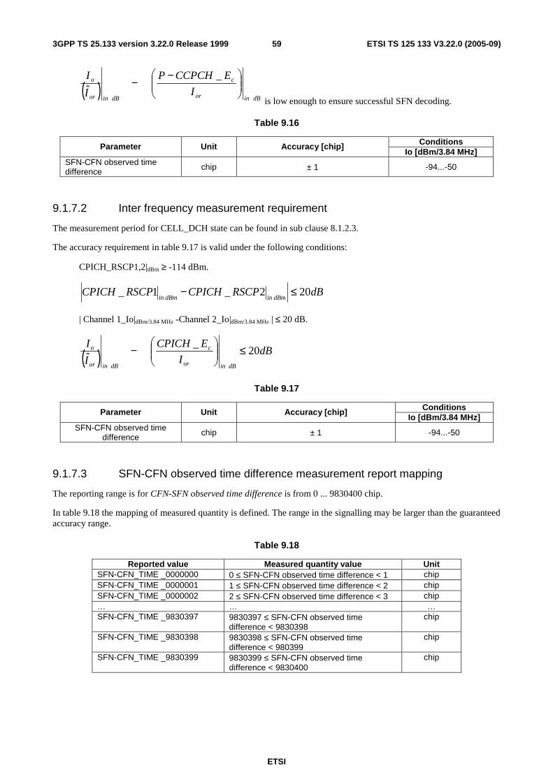
ETSI
ETSI TS 125 133 V3.22.0 (2005-09) 593GPP TS 25.133 version 3.22.0 Release 1999
( )
dBinor
c
dBinor
o
I
ECCPCHP
I
I
−−
_ˆ
is low enough to ensure successful SFN decoding.
Table 9.16
Conditions Parameter Unit Accuracy [chip] Io [dBm/3.84 MHz]
SFN-CFN observed time difference chip ± 1 -94...-50
9.1.7.2 Inter frequency measurement requirement
The measurement period for CELL_DCH state can be found in sub clause 8.1.2.3.
The accuracy requirement in table 9.17 is valid under the following conditions:
CPICH_RSCP1,2|dBm ≥ -114 dBm.
dBRSCPCPICHRSCPCPICHdBmindBmin
202_1_ ≤−
| Channel 1_Io|dBm/3.84 MHz -Channel 2_Io|dBm/3.84 MHz | ≤ 20 dB.
( ) dBI
ECPICH
I
I
dBinor
c
dBinor
o 20_
ˆ≤
−
Table 9.17
Conditions Parameter Unit Accuracy [chip] Io [dBm/3.84 MHz]
SFN-CFN observed time difference chip ± 1 -94...-50
9.1.7.3 SFN-CFN observed time difference measurement report mapping
The reporting range is for CFN-SFN observed time difference is from 0 ... 9830400 chip.
In table 9.18 the mapping of measured quantity is defined. The range in the signalling may be larger than the guaranteed accuracy range.
Table 9.18
Reported value Measured quantity value Unit SFN-CFN_TIME _0000000 0 ≤ SFN-CFN observed time difference < 1 chip SFN-CFN_TIME _0000001 1 ≤ SFN-CFN observed time difference < 2 chip SFN-CFN_TIME _0000002 2 ≤ SFN-CFN observed time difference < 3 chip … … … SFN-CFN_TIME _9830397 9830397 ≤ SFN-CFN observed time
difference < 9830398 chip
SFN-CFN_TIME _9830398 9830398 ≤ SFN-CFN observed time difference < 980399
chip
SFN-CFN_TIME _9830399 9830399 ≤ SFN-CFN observed time difference < 9830400
chip

ETSI
ETSI TS 125 133 V3.22.0 (2005-09) 603GPP TS 25.133 version 3.22.0 Release 1999
9.1.8 SFN-SFN observed time difference
9.1.8.1 SFN-SFN observed time difference type 1
NOTE: This measurement is for identifying time difference between two cells.
9.1.8.1.1 Measurement requirement
The measurement period for CELL_FACH state can be found in sub clause 8.4.2.2.
The accuracy requirement in table 9.19 is valid under the following conditions:
CPICH_RSCP1,2|dBm ≥ -114 dBm.
dBRSCPCPICHRSCPCPICHdBmindBmin
202_1_ ≤−
( ) dBI
ECPICH
I
I
dBinor
c
dBinor
o 20_
ˆ≤
−
( )
dBinor
c
dBinor
o
I
ECCPCHP
I
I
−−
_ˆ
is low enough to ensure successful SFN decoding.
Table 9.19
Conditions Parameter Unit Accuracy [chip] Io [dBm/3.84 MHz]
SFN-SFN observed time difference type1 chip ± 1 -94...-50
9.1.8.1.2 SFN-SFN observed time difference type 1 measurement report mapping
The reporting range is for SFN-SFN observed time difference type 1 is from 0 ... 9830400 chip.
In table 9.20 the mapping of measured quantity is defined. The range in the signalling may be larger than the guaranteed accuracy range.
Table 9.20
Reported value Measured quantity value Unit T1_SFN-SFN_TIME _0000000 0 ≤ SFN-SFN observed time difference type
1 < 1 chip
T1_SFN-SFN_TIME _0000001 1 ≤ SFN-SFN observed time difference type 1 < 2
chip
T1_SFN-SFN_TIME _0000002 2 ≤ SFN-SFN observed time difference type 1 < 3
chip
… … … T1_SFN-SFN_TIME _9830397 9830397 ≤ SFN-SFN observed time
difference type 1 < 9830398 chip
T1_SFN-SFN_TIME _9830398 9830398 ≤ SFN-SFN observed time difference type 1 < 980399
chip
T1_SFN-SFN_TIME _9830399 9830399 ≤ SFN-SFN observed time difference type 1 < 9830400
chip
9.1.8.2 SFN-SFN observed time difference type 2
NOTE: This measurement is for location service purposes to identify time difference between two cells.

ETSI
ETSI TS 125 133 V3.22.0 (2005-09) 613GPP TS 25.133 version 3.22.0 Release 1999
It is optional for terminal to support the use of IPDL periods together with SFN-SFN observed time difference type 2. The support of IPDL depends on the supported UE positioning methods.
NOTE: Requirement on the UE shall be reconsidered when the state of the art technology progress.
9.1.8.2.1 Intra frequency measurement requirement accuracy without IPDL period active
The measurement period for CELL_DCH state can be found in sub clause 8.1.2.2. The measurement period for CELL_FACH state can be found in sub clause 8.4.2.2.
The accuracy requirement in table 9.21 is valid under the following conditions:
CPICH_RSCP1,2|dBm ≥ -114 dBm.
( ) dBI
ECPICH
I
I
dBinor
c
dBinor
o 20_
ˆ≤
−
Table 9.21
Conditions Parameter Unit Accuracy [chip] Io [dBm/3.84 MHz]
SFN-SFN observed time difference type2 chip ± 0.5 -94...-50
9.1.8.2.2 Intra frequency measurement requirement accuracy with IPDL period active
This requirement is valid only for UEs supporting IPDL measurements.
The measurement period for CELL_DCH state can be found in sub clause 8.1.2.2. The measurement period for CELL_FACH state can be found in sub clause 8.4.2.2.
The accuracy requirement in table 9.22 is valid under the following conditions:
CPICH_RSCP1,2|dBm ≥ -114 dBm.
( ) dBI
ECPICH
I
I
dBinor
c
dBinor
o 20_
ˆ≤
−
Additionally the accuracy requirement in table 9.22 is also valid for neighbour cells for which the following conditions apply to during idle periods provided idle periods have a length of 1 slot:
CPICH_RSCPx,y|dBm ≥ -114 dBm.
( ) dBI
ECPICH
I
I
dBinor
c
dBinor
periodidleo 20_
ˆ__ ≤
− ,
where x and y represent cells measured using idle periods and Io_idle-period is the total received power during the idle period.
NOTE: Additional general conditions are needed for the requirements in table 9.22 to be valid.
Table 9.22
Conditions Parameter Unit Accuracy [chip]
Io [dBm/3.84 MHz]
SFN-SFN observed time difference type 2
chip ± 0.5 -94...-50

ETSI
ETSI TS 125 133 V3.22.0 (2005-09) 623GPP TS 25.133 version 3.22.0 Release 1999
9.1.8.2.3 Inter frequency measurement requirement accuracy
The measurement period for CELL_DCH state can be found in sub clause 8.1.2.3. The measurement period for CELL_FACH state can be found in sub clause 8.4.2.3.
The accuracy requirement in table 9.23 is valid under the following conditions:
CPICH_RSCP1,2|dBm ≥ -114 dBm.
| Channel 1_Io|dBm/3.84 MHz -Channel 2_Io|dBm/3.84 MHz | ≤ 20 dB.
( ) dBI
ECPICH
I
I
dBinor
c
dBinor
o 20_
ˆ≤
−
Table 9.23
Conditions Parameter Unit Accuracy [chip] Io [dBm/3.84 MHz]
SFN-SFN observed time difference type 2 chip ± 1 -94...-50
9.1.8.2.4 SFN-SFN observed time difference type 2 measurement report mapping
The reporting range is for SFN-SFN observed time difference type 2 is from -1280 ... +1280 chip.
In table 9.24 the mapping of measured quantity is defined. The range in the signalling may be larger than the guaranteed accuracy range.
Table 9.24
Reported value Measured quantity value Unit T2_SFN-SFN_TIME _00000 SFN-SFN observed time difference type 2 < -1280.0000 chip T2_SFN-SFN_TIME _00001 -1280.0000 ≤ SFN-SFN observed time difference type 2 < -1279.9375 chip T2_SFN-SFN_TIME _00002 -1279.9375 ≤ SFN-SFN observed time difference type 2 < -1279.8750 chip … … … T2_SFN-SFN_TIME _40959 1279.8750 ≤ SFN-SFN observed time difference type 2 < 1279.9375 chip T2_SFN-SFN_TIME _40960 1279.9375 ≤ SFN-SFN observed time difference type 2 < 1280.0000 chip T2_SFN-SFN_TIME _40961 1280.0000 ≤ SFN-SFN observed time difference type 2 chip
9.1.9 UE Rx-Tx time difference
9.1.9.1 UE Rx-Tx time difference type 1
NOTE: This measurement is used for call set up purposes to compensate propagation delay of DL and UL.
The measurement period in CELL_DCH state is 100 ms
9.1.9.1.1 Measurement requirement
Table 9.25
Conditions Parameter Unit Accuracy [chip] Io [dBm/3.84 MHz]
UE RX-TX time difference chip ± 1.5 -94...-50

ETSI
ETSI TS 125 133 V3.22.0 (2005-09) 633GPP TS 25.133 version 3.22.0 Release 1999
9.1.9.1.2 UE Rx-Tx time difference type 1 measurement report mapping
The reporting range is for UE Rx-Tx time difference type 1 is from 768 ... 1280 chip.
In table 9.26 the mapping of measured quantity is defined. The range in the signalling may be larger than the guaranteed accuracy range.
Table 9.26
Reported value Measured quantity value Unit RX-TX_TIME _768 UE Rx-Tx Time difference type 1< 768 chip RX-TX_TIME _769 768≤ UE Rx-Tx Time difference type 1< 769 chip RX-TX_TIME _770 769≤ UE Rx-Tx Time difference type 1< 770 chip RX-TX_TIME _771 770 ≤ UE Rx-Tx Time difference type 1< 771 chip … … … RX-TX_TIME _1277 1276 ≤ UE Rx-Tx Time difference type 1< 1277 chip RX-TX_TIME _1278 1277 ≤ UE Rx-Tx Time difference type 1< 1278 chip RX-TX_TIME _1279 1278 ≤ UE Rx-Tx Time difference type 1< 1279 chip RX-TX_TIME _1280 1279 ≤ UE Rx-Tx Time difference type 1 chip
9.1.9.2 UE Rx-Tx time difference type 2
NOTE: This measurement is used for UE positioning purposes.
It is optional for a terminal to support a subset of UE positioning methods. This measurement represents an instantaneous value that is time stamped as defined in the IE description in TS 25.331 [16].
9.1.9.2.1 Measurement requirement
Table 9.27
Conditions Parameter Unit Accuracy [chip] Io [dBm/3.84 MHz]
UE RX-TX time difference chip ± 1.0 -94...-50
9.1.9.2.2 UE Rx-Tx time difference type 2 measurement report mapping
The reporting range is for UE Rx-Tx time difference type2 is from 768 ... 1280 chip.
In table 9.28 the mapping of measured quantity is defined. The range in the signalling may be larger than the guaranteed accuracy range.
Table 9.28
Reported value Measured quantity value Unit RX-TX_TIME _0000 UE Rx-Tx Time difference type 2 < 768.000 chip RX-TX_TIME _0001 768.000 ≤ UE Rx-Tx Time difference type 2 < 768.0625 chip RX-TX_TIME _0002 768.0625 ≤ UE Rx-Tx Time difference type 2 < 768.1250 chip RX-TX_TIME _0003 768.1250 ≤ UE Rx-Tx Time difference type 2 < 768.1875 chip … … … RX-TX_TIME _8189 1279.7500 ≤ UE Rx-Tx Time difference type 2 < 1279.8125 chip RX-TX_TIME _8190 1279.8125 ≤ UE Rx-Tx Time difference type 2 < 1279.8750 chip RX-TX_TIME _8191 1279.8750 ≤ UE Rx-Tx Time difference type 2 chip
9.1.10 Observed time difference to GSM cell
NOTE: This measurement is used to determine the system time difference between UTRAN and GSM cells.
The requirements in this section are valid for terminals supporting UTRA and GSM.

ETSI
ETSI TS 125 133 V3.22.0 (2005-09) 643GPP TS 25.133 version 3.22.0 Release 1999
9.1.10.1 Measurement requirement
The measurement period for CELL_DCH state is equal to the maximum time between two successive BSIC re-confirmations for one particular GSM cell according to sub clause 8.1.2.5.2.
NOTE: The conditions for which the accuracy requirement in table 9.29 is valid are FFS.
Table 9.29
Parameter Unit Accuracy [chip] Conditions Observed time difference to GSM cell ms ± 20
9.1.10.2 Observed time difference to GSM cell measurement report mapping
The reporting range is for Observed time difference to GSM cell is from 0 ... 3060/13 ms.
In table 9.30 the mapping of measured quantity is defined. The range in the signalling may be larger than the guaranteed accuracy range.
Table 9.30
Reported value Measured quantity value Unit GSM_TIME _0000 0 ≤ Observed time difference to GSM cell < 1x3060/(4096x13) ms GSM_TIME _0001 1x3060/(4096x13) ≤ Observed time difference to GSM cell < 2x3060/(4096x13) ms GSM_TIME _0002 2x3060/(4096x13)≤ Observed time difference to GSM cell < 3x3060/(4096x13) ms GSM_TIME _0003 3x3060/(4096x13) ≤ Observed time difference to GSM cell < 4x3060/(4096x13) ms … … … GSM_TIME _4093 4093x3060/(4096x13) ≤ Observed time difference to GSM cell <
4094x3060/(4096x13) ms
GSM_TIME _4094 4094x3060/(4096x13) ≤ Observed time difference to GSM cell < 4095x3060/(4096x13)
ms
GSM_TIME _4095 4095x3060/(4096x13) ≤ Observed time difference to GSM cell < 3060/13 ms
9.1.11 P-CCPCH RSCP
NOTE: This measurement is used for handover between UTRA FDD and UTRA TDD.
The requirements in this section are valid for terminals supporting this capability.
The measurement period for CELL_DCH state can be found in sub clause 8.1.2.4. The measurement period for CELL_FACH state can be found in sub clause 8.4.2.4.
9.1.11.1 Absolute accuracy requirements
The accuracy requirement in table 9.31is valid under the following conditions:
P-CCPCH_RSCP ≥ -102 dBm.
( ) dBI
ECCPCHP
I
I
dBinor
c
dBinor
o 8_
ˆ≤
−−
Table 9.31: P-CCPCH_RSCP Inter frequency absolute accuracy
Accuracy [dB] Conditions Parameter Unit
Normal conditions Extreme conditions Io [dBm/3.84 MHz]
dBm ± 6 ± 9 -94...-70 P-CCPCH_RSCP
dBm ± 8 ± 11 -70...-50

ETSI
ETSI TS 125 133 V3.22.0 (2005-09) 653GPP TS 25.133 version 3.22.0 Release 1999
9.1.11.2 P-CCPCH RSCP measurement report mapping
The reporting range is for P-CCPCH RSCP is from -115 ... -25 dBm.
In table 9.32 the mapping of measured quantity is defined. The range in the signalling may be larger than the guaranteed accuracy range.
Table 9.32
Reported value Measured quantity value Unit PCCPCH_RSCP_LEV _00 PCCPCH RSCP< -115 dBm PCCPCH_RSCP_LEV _01 -115 ≤ PCCPCH RSCP< -114 dBm PCCPCH_RSCP_LEV _02 -114 ≤ PCCPCH RSCP< -113 dBm PCCPCH_RSCP_LEV _03 -113 ≤ PCCPCH RSCP< -112 dBm … … … PCCPCH_RSCP_LEV _89 -27 ≤ PCCPCH RSCP< -26 dBm PCCPCH_RSCP_LEV _90 -26 ≤ PCCPCH RSCP< -25 dBm PCCPCH_RSCP_LEV _91 -25 ≤ PCCPCH RSCP dBm
9.1.12 UE GPS Timing of Cell Frames for UE positioning
The requirements in this section are valid for terminals supporting this capability:
Table 9.33
Parameter Unit Accuracy [chip] Conditions UE GPS Timing of Cell Frames for UE positioning chip [ ]
9.1.12.1 UE GPS timing of Cell Frames for UE positioning measurement report mapping
The reporting range is for UE GPS timing of Cell Frames for UE positioning is from 0 ... 2322432000000 chip.
In table 9.34 the mapping of measured quantity is defined.
Table 9.34
Reported value Measured quantity value Unit GPS_TIME_00000000000000 UE GPS timing of Cell Frames for UE positioning < 0.0625 chip GPS_TIME_00000000000001 0.0625 ≤ UE GPS timing of Cell Frames for UE positioning <
0.1250 chip
GPS_TIME_00000000000002 0.1250 ≤ UE GPS timing of Cell Frames for UE positioning < 0.1875
chip
... ... ... GPS_TIME_37158911999997 2322431999999.8125 ≤ UE GPS timing of Cell Frames for
UE positioning < 2322431999999.8750 chip
GPS_TIME_37158911999998 2322431999999.8750 ≤ UE GPS timing of Cell Frames for UE positioning < 2322431999999.9375
chip
GPS_TIME_37158911999999 2322431999999.9375 ≤ UE GPS timing of Cell Frames for UE positioning < 2322432000000.0000
chip

ETSI
ETSI TS 125 133 V3.22.0 (2005-09) 663GPP TS 25.133 version 3.22.0 Release 1999
9.2 Measurements Performance for UTRAN The reported measurement result after layer 1 filtering shall be an estimate of the average value of the measured quantity over the measurement period. The reference point for the measurement result after layer 1 filtering is referred to as point B in the measurement model described in TS 25.302.
The accuracy requirements in this clause are valid for the reported measurement result after layer 1 filtering. The accuracy requirements are verified from the measurement report at point D in the measurement model having the layer 3 filtering disabled.
9.2.1 Received total wideband power
The measurement period shall be 100 ms.
9.2.1.1 Absolute accuracy requirement
Table 9.35
Conditions Parameter Unit Accuracy [dB] Range
Io dBm/3.84 MHz ± 4 –103<= Io <= -74 dBm/3.84 MHz
9.2.1.2 Relative accuracy requirement
The relative accuracy is defined as the Received total wideband power measured at one frequency compared to the Received total wideband power measured from the same frequency at a different time.
Table 9.36
Conditions Parameter Unit Accuracy [dB] Range
Io dBm/3.84 MHz ± 0.5- For changes <= ±5.0dB and –103 <= Io <= -74dBm/3.84 MHz
9.2.1.3 Received total wideband power measurement report mapping
The reporting range for Received total wideband power (RTWP) is from -112 ... -50 dBm.
In table 9.37 the mapping of measured quantity is defined. The range in the signalling may be larger than the guaranteed accuracy range.
Table 9.37
Reported value Measured quantity value Unit RTWP_LEV _000 RTWP < -112.0 dBm RTWP_LEV _001 -112.0 ≤ RTWP < -111.9 dBm RTWP_LEV _002 -111.9 ≤ RTWP < -111.8 dBm … … … RTWP_LEV _619 -50.2 ≤ RTWP < -50.1 dBm RTWP_LEV _620 -50.1 ≤ RTWP < -50.0 dBm RTWP_LEV _621 -50.0 ≤ RTWP dBm

ETSI
ETSI TS 125 133 V3.22.0 (2005-09) 673GPP TS 25.133 version 3.22.0 Release 1999
9.2.2 SIR
The measurement period shall be 80 ms.
9.2.2.1 Accuracy requirement
Table 9.38
Conditions Parameter Unit Accuracy [dB] Range
SIR dB ± 3 For -7<SIR<20 dB when Io > -105 dBm/3.84 MHz
9.2.2.2 SIR measurement report mapping
The reporting range for SIR is from -11 ... 20 dB.
In table 9.39 the mapping of measured quantity is defined. The range in the signalling may be larger than the guaranteed accuracy range.
Table 9.39
Reported value Measured quantity value Unit UTRAN_SIR_00 SIR < -11.0 dB UTRAN_SIR_01 -11.0 ≤ SIR < -10.5 dB UTRAN_SIR_02 -10.5 ≤ SIR < -10.0 dB … … … UTRAN_SIR_61 19.0 ≤ SIR < 19.5 dB UTRAN_SIR_62 19.5 ≤ SIR < 20.0 dB UTRAN_SIR_63 20.0 ≤ SIR dB
9.2.3 SIRerror
The measurement period shall be 80 ms.
NOTE: The measurement period is the same as for the SIR measurement in section 9.2.2. SIRerror is calculated from SIR and SIRtarget, see TS 25.215.
9.2.3.1 Accuracy requirement
Table 9.40
Parameter Accuracy Range
SIRerror ± 3 dB The accuracy requirement for SIRerror is valid for SIR within the guaranteed accuarcy range specified in section 9.2.2.
NOTE: The accuracy requirement for SIRerror is the same as for the SIR measurement specified in section 9.2.2. SIRerror is calculated from SIR and SIRtarget, see TS 25.215.
9.2.3.2 SIRerror measurement report mapping
The reporting range for SIRerror is from -31 ... 31 dB.
In table 9.41 the mapping of measured quantity is defined. The range in the signalling may be larger than the guaranteed accuracy range.

ETSI
ETSI TS 125 133 V3.22.0 (2005-09) 683GPP TS 25.133 version 3.22.0 Release 1999
Table 9.41
Reported value Measured quantity value Unit UTRAN_SIR_ERROR_000 SIRerror < -31.0 dB UTRAN_SIR_ERROR_001 -31.0 ≤ SIRerror < -30.5 dB UTRAN_SIR_ERROR_002 -30.5 ≤ SIRerror < -30.0 dB … … … UTRAN_SIR_ERROR_062 -0.5 ≤ SIRerror < 0.0 dB UTRAN_SIR_ERROR_063 0.0 ≤ SIRerror < 0.5 dB … … … UTRAN_SIR_ERROR_123 30.0 ≤ SIRerror < 30.5 dB UTRAN_SIR_ERROR_124 30.5 ≤ SIRerror < 31.0 dB UTRAN_SIR_ERROR_125 31.0 ≤ SIRerror dB
9.2.4 Transmitted carrier power
The measurement period shall be 100 ms.
9.2.4.1 Accuracy requirement
Table 9.42
Conditions Parameter Unit Accuracy [% units] Range
Ptot % ± 5 For 5% ≤ Transmitted carrier power ≤95%
9.2.4.2 Transmitted carrier power measurement report mapping
The reporting range for Transmitted carrier power is from 0 ... 100 %.
In table 9.43 the mapping of measured quantity is defined. The range in the signalling may be larger than the guaranteed accuracy range.
Table 9.43
Reported value Measured quantity value Unit UTRAN_TX_POWER _000 Transmitted carrier power = 0 % UTRAN_TX_POWER _001 0 < Transmitted carrier power ≤ 1 % UTRAN_TX_POWER _002 1 < Transmitted carrier power ≤ 2 % UTRAN_TX_POWER _003 2 < Transmitted carrier power ≤ 3 % … … … UTRAN_TX_POWER _098 97 < Transmitted carrier power ≤ 98 % UTRAN_TX_POWER _099 98 < Transmitted carrier power ≤ 99 % UTRAN_TX_POWER _100 99 < Transmitted carrier power ≤ 100 %
9.2.5 Transmitted code power
The measurement period shall be 100 ms.
9.2.5.1 Absolute accuracy requirement
Table 9.44
Conditions Parameter Unit Accuracy [dB] Range
Pcode dBm ± 3 Over the full range

ETSI
ETSI TS 125 133 V3.22.0 (2005-09) 693GPP TS 25.133 version 3.22.0 Release 1999
9.2.5.2 Relative accuracy requirement
The relative accuracy of Transmitted code power is defined as the Transmitted code power measured at one dedicated radio link compared to the Transmitted code power measured from a different dedicated radio link in the same cell.
Table 9.45
Conditions Parameter Unit Accuracy [dB] Range
Pcode dBm ± 2 Over the full range
9.2.5.3 Transmitted code power measurement report mapping
The reporting range for Transmitted code power is from -10 ... 46 dBm.
In table 9.46 the mapping of measured quantity is defined. The range in the signalling may be larger than the guaranteed accuracy range.
Table 9.46
Reported value Measured quantity value Unit UTRAN_CODE_POWER _010 -10.0 ≤ Transmitted code power < -9.5 dBm UTRAN_CODE_POWER _011 -9.5 ≤ Transmitted code power < -9.0 dBm UTRAN_CODE_POWER _012 -9.0 ≤ Transmitted code power < -8.5 dBm … … … UTRAN_CODE_POWER _120 45.0 ≤ Transmitted code power < 45.5 dBm UTRAN_CODE_POWER _121 45.5 ≤ Transmitted code power < 46.0 dBm UTRAN_CODE_POWER _122 46.0 ≤ Transmitted code power < 46.5 dBm
9.2.6 Void
9.2.7 Physical channel BER
The measurement period shall be equal to the TTI of the transport channel, to which the Physical channel BER is associated via the IE QE-Selector, see TS 25.433. Each reported Physical channel BER measurement shall be an estimate of the BER averaged over one measurement period only.
9.2.7.1 Accuracy requirement
The average of consecutive Physical channel BER measurements is required to fulfil the accuracy stated in table 9.47 if the total number of erroneous bits during these measurements is at least 500 and the absolute BER value for each of the measurements is within the range given in table 9.47.
Table 9.47
Conditions Parameter Unit Accuracy [% of absolute BER value] Range
PhyBER - +/- 10 for absolute BER value ≤ 30%
9.2.7.2 Physical channel BER measurement report mapping
The Physical channel BER reporting range is from 0 to 1.
In table 9.48 the mapping of measured quantity is defined. The range in the signalling may be larger than the guaranteed accuracy range.

ETSI
ETSI TS 125 133 V3.22.0 (2005-09) 703GPP TS 25.133 version 3.22.0 Release 1999
Table 9.48
Reported value Measured quantity value Unit PhCh_BER_LOG_000 Physical channel BER = 0 - PhCh_BER_LOG_001 -∞ < Log10(Physical channel BER) < -2.06375 - PhCh_BER_LOG_002 -2.06375≤ Log10(Physical channel BER) < -2.055625 - PhCh_BER_LOG_003 -2.055625 ≤ Log10(Physical channel BER) < -2.0475 - … … … PhCh_BER_LOG_253 -0.024375 ≤ Log10(Physical channel BER) < -0.01625 - PhCh_BER_LOG_254 -0.01625 ≤ Log10(Physical channel BER) < -0.008125 - PhCh_BER_LOG_255 -0.008125 ≤ Log10(Physical channel BER) ≤ 0 -
9.2.8 Round trip time
The measurement period shall be 100 ms.
9.2.8.1 Absolute accuracy requirement
Table 9.49
Conditions Parameter Unit Accuracy [chip] Range [chips]
RTT chip +/- 0.5 876, …, 2923.50
9.2.8.2 Round trip time measurement report mapping
The Round trip time reporting range is from 876.0000 ... 2923.8750 chip.
In table 9.50 the mapping of measured quantity is defined. The range in the signalling may be larger than the guaranteed accuracy range.
Table 9.50
Reported value Measured quantity value Unit RT_TIME_0000 Round trip time < 876.0000 chip RT_TIME_0001 876.0000 ≤ Round trip time < 876.0625 chip RT_TIME_0002 876.0625 ≤ Round trip time < 876.1250 chip RT_TIME_0003 876.1250 ≤ Round trip time < 876.1875 chip … … … RT_TIME_32764 2922.6875 ≤ Round trip time < 2923.7500 chip RT_TIME_32765 2923.7500 ≤ Round trip time < 2923.8125 chip RT_TIME_32766 2923.8125 ≤ Round trip time < 2923.8750 chip RT_TIME_32767 2923.8750 ≤ Round trip time chip
9.2.9 Transport Channel BER
The measurement period shall be equal to the TTI of the transport channel. Each reported Transport channel BER measurement shall be an estimate of the BER averaged over one measurement period only.
9.2.9.1 Accuracy requirement
The average of consecutive Transport channel BER measurements is required to fulfil the accuracy stated in table 9.51 if the total number of erroneous bits during these measurements is at least 500 and the absolute BER value for each of the measurements is within the range given in table 9.51.

ETSI
ETSI TS 125 133 V3.22.0 (2005-09) 713GPP TS 25.133 version 3.22.0 Release 1999
Table 9.51
Conditions Parameter Unit Accuracy [% of the absolute BER value] Range
TrpBER - +/- 10 Convolutional coding 1/3rd with any amount of repetition or a maximum of 25% puncturing: for absolute BER value ≤ 15% Convolutional coding 1/2 with any amount of repetition or no puncturing: for absolute BER value ≤ 15% Turbo coding 1/3rd with any amount of repetition or a maximum of 20% puncturing: for absolute BER value ≤ 15%.
9.2.9.2 Transport channel BER measurement report mapping
The Transport channel BER reporting range is from 0 to 1.
In table 9.52 the mapping of measured quantity is defined. The range in the signalling may be larger than the guaranteed accuracy range.
Table 9.52
Reported value Measured quantity value Unit TrCh_BER_LOG_000 Transport channel BER = 0 - TrCh_BER_LOG_001 -∞ < Log10(Transport channel BER) < -2.06375 - TrCh_BER_LOG_002 -2.06375≤ Log10(Transport channel BER) < -2.055625 - TrCh_BER_LOG_003 -2.055625 ≤ Log10(Transport channel BER) < -2.0475 - … … … TrCh_BER_LOG_253 -0.024375 ≤ Log10(Transport channel BER) < -0.01625 - TrCh_BER_LOG_254 -0.01625 ≤ Log10(Transport channel BER) < -0.008125 - TrCh_BER_LOG_255 -0.008125 ≤ Log10(Transport channel BER) ≤ 0 -
9.2.10 UTRAN GPS Timing of Cell Frames for UE positioning
Table 9.53
Parameter Unit Accuracy [chip] Conditions UTRAN GPS Timing of Cell Frames for UE positioning
chip [ ]
9.2.10.1 UTRAN GPS timing of Cell Frames for UE positioning measurement report mapping
The reporting range is for UTRAN GPS timing of Cell Frames for UE positioning is from 0 ... 2322432000000 chip.
In table 9.54 the mapping of measured quantity is defined.

ETSI
ETSI TS 125 133 V3.22.0 (2005-09) 723GPP TS 25.133 version 3.22.0 Release 1999
Table 9.54
Reported value Measured quantity value Unit GPS_TIME_00000000000000 UTRAN GPS timing of Cell Frames for UE
positioning < 0.0625 chip
GPS_TIME_00000000000001 0.0625 ≤ UTRAN GPS timing of Cell Frames for UE positioning < 0.1250
chip
GPS_TIME_00000000000002 0.1250 ≤ UTRAN GPS timing of Cell Frames for UE positioning < 0.1875
chip
… … … GPS_TIME_37158911999997 2322431999999.8125 ≤ UTRAN GPS timing of Cell
Frames for UE positioning < 2322431999999.8750 chip
GPS_TIME_37158911999998 2322431999999.8750 ≤ UTRAN GPS timing of Cell Frames for UE positioning < 2322431999999.9375
chip
GPS_TIME_37158911999999 2322431999999.9375 ≤ UTRAN GPS timing of Cell Frames for UE positioning < 2322432000000.0000
chip
9.2.11 PRACH/PCPCH Propagation delay
9.2.11.1 Accuracy requirement
Table 9.55
Conditions Parameter Unit Accuracy [chip] Range
PropDelay chip +/- []
9.2.11.2 PRACH/PCPCH Propagation delay measurement report mapping
The PRACH/PCPCH Propagation delay reporting range is from 0 ... 765 chip.
In table 9.56 the mapping of measured quantity is defined. The range in the signalling may be larger than the guaranteed accuracy range.
Table 9.56
Reported value Measured quantity value Unit PROP_DELAY_000 0 ≤ PRACH/PCPCH Propagation delay < 3 chip PROP_DELAY_001 3 ≤ PRACH/PCPCH Propagation delay < 6 chip PROP_DELAY_002 6 ≤ PRACH/PCPCH Propagation delay < 9 chip … … … PROP_DELAY_252 756 ≤ PRACH/PCPCH Propagation delay < 759 chip PROP_DELAY_253 759 ≤ PRACH/PCPCH Propagation delay < 762 chip PROP_DELAY_254 762 ≤ PRACH/PCPCH Propagation delay < 765 chip PROP_DELAY_255 765 ≤ PRACH/PCPCH Propagation delay chip
9.2.12 Acknowledged PRACH preambles
The measurement period shall be 20 ms.
9.2.12.1 Acknowledged PRACH preambles measurement report mapping
The Acknowledged PRACH preambles reporting range is from 0 ... 240 acknowledgements.
In table 9.57 the mapping of measured quantity is defined. The range in the signalling may be larger than the guaranteed accuracy range.

ETSI
ETSI TS 125 133 V3.22.0 (2005-09) 733GPP TS 25.133 version 3.22.0 Release 1999
Table 9.57
Reported value Measured quantity value Unit ACK_PRACH_PREAMPLE_000 Acknowledged PRACH preambles = 0 - ACK_PRACH_PREAMPLE_001 Acknowledged PRACH preambles = 1 - ACK_PRACH_PREAMPLE_002 Acknowledged PRACH preambles = 2 - … … … ACK_PRACH_PREAMPLE_237 Acknowledged PRACH preambles = 237 - ACK_PRACH_PREAMPLE_238 Acknowledged PRACH preambles = 238 - ACK_PRACH_PREAMPLE_239 Acknowledged PRACH preambles = 239 - ACK_PRACH_PREAMPLE_240 Acknowledged PRACH preambles = 240 -
9.2.13 Detected PCPCH access preambles
The measurement period shall be 20 ms.
9.2.13.1 Detected PCPCH access preambles measurement report mapping
The Detected PCPCH access preambles reporting range is 0 … 240.
In Table 9.58, the mapping of measured quantity is defined. The range in the signalling may be larger than the guaranteed accuracy range.
Table 9.58
Reported value Measured quantity value Unit DETECT_PCPCH_AP_000 Detected PCPCH access preambles = 0 - DETECT_PCPCH_AP _001 Detected PCPCH access preambles = 1 - DETECT_PCPCH_AP _002 Detected PCPCH access preambles = 2 - … … … DETECT_PCPCH_AP _237 Detected PCPCH access preambles = 237 - DETECT_PCPCH_AP _238 Detected PCPCH access preambles = 238 - DETECT_PCPCH_AP _239 Detected PCPCH access preambles = 239 - DETECT_PCPCH_AP _240 Detected PCPCH access preambles = 240 -
9.2.14 Acknowledged PCPCH access preambles
The measurement period shall be 20 ms.
9.2.14.1 Acknowledged PCPCH access preambles measurement report mapping
The Acknowledged PCPCH access preambles reporting range is 0 … 15.
In Table 9.59, the mapping of measured quantity is defined. The range in the signalling may be larger than the guaranteed accuracy range.
Table 9.59
Reported value Measured quantity value Unit ACK_PCPCH_AP_00 Acknowledged PCPCH access preambles = 0 - ACK_PCPCH_AP _01 Acknowledged PCPCH access preambles = 1 - ACK_PCPCH_AP _02 Acknowledged PCPCH access preambles = 2 - … … … ACK_PCPCH_AP _12 Acknowledged PCPCH access preambles = 12 - ACK_PCPCH_AP _13 Acknowledged PCPCH access preambles = 13 - ACK_PCPCH_AP _14 Acknowledged PCPCH access preambles = 14 - ACK_PCPCH_AP _15 Acknowledged PCPCH access preambles = 15 -

ETSI
ETSI TS 125 133 V3.22.0 (2005-09) 743GPP TS 25.133 version 3.22.0 Release 1999
Annex A (normative): Test Cases
A.1 Purpose of Annex This Annex specifies test specific parameters for some of the functional requirements in chapters 4 to 9. The tests provide additional information to how the requirements should be interpreted for the purpose of conformance testing. The tests in this Annex are described such that one functional requirement may be tested in one or several test and one test may verify several requirements. Some requirements may lack a test.
The conformance tests are specified in TS34.121.
For this release all test cases can now be found in the equivalent release of TS 34.121.
A.2 Void
A.3 Void
A.4 Void
A.5 Void
A.6 Void
A.7 Void
A.8 Void

ETSI
ETSI TS 125 133 V3.22.0 (2005-09) 753GPP TS 25.133 version 3.22.0 Release 1999
A.9 Void

ETSI
ETSI TS 125 133 V3.22.0 (2005-09) 763GPP TS 25.133 version 3.22.0 Release 1999
Annex B (informative): Change History Initial version at TSG-RAN#6 (December 1999): 3.0.0
Table B.1: CRs approved by TSG-RAN#7.
RAN Doc Spec CR R Ph Subject Cat Curr New RP-000021 25.133 001 R99 Modification of RL Failure Requirement F 3.0.0 3.1.0 RP-000021 25.133 002 R99 Idle Mode Tasks C 3.0.0 3.1.0 RP-000021 25.133 003 R99 Revised UE handover requirements F 3.0.0 3.1.0 RP-000021 25.133 004 R99 Editorial corrections D 3.0.0 3.1.0 RP-000021 25.133 005 R99 UE measurement requirement update F 3.0.0 3.1.0 RP-000021 25.133 006 R99 TDD Measurements Performance Requirements for TS25.133
(FDD) B 3.0.0 3.1.0
RP-000021 25.133 007 R99 UTRAN measurement requirement update F 3.0.0 3.1.0 RP-000021 25.133 008 R99 Requirements on parallel measurements F 3.0.0 3.1.0 RP-000021 25.133 009 R99 Inclusion on transport channel BER. F 3.0.0 3.1.0
Note: On implementation of CR 25.133-003: On page 16 there is a dotted line above title 5.1.2.1.4 ACTIVE SET DIMENSION. The text following is a duplication of version 3.0.0 to the point of sub-clause 5.1.2.2.1.3. HARD HANDOVER DELAY. Therefore all text from page 16 starting from 5.1.2.1.4 ACTIVE SET DIMENSION is moved to sub-clause 5.1.2.2.1.3 HARD HANDOVER DELAY on page 19.
Table B.2: CRs approved by TSG-RAN#8.
RAN Doc Spec CR R Ph Subject Cat Curr New RP-000210 25.133 010 R99 Measurement period for UTRAN SIR F 3.1.0 3.2.0 RP-000210 25.133 011 R99 Measurement period for UE BLER F 3.1.0 3.2.0 RP-000210 25.133 013 R99 Measurement delay reporting F 3.1.0 3.2.0 RP-000210 25.133 015 R99 Correction - Propagation conditions F 3.1.0 3.2.0 RP-000210 25.133 016 R99 Remove requirements on SSDT from 5.1.1.8. D 3.1.0 3.2.0 RP-000210 25.133 017 R99 Update of test parameters to P-CCPCH Measurements
performance requirements F 3.1.0 3.2.0
RP-000210 25.133 018 R99 Repetition Period of System Information F 3.1.0 3.2.0 RP-000210 25.133 019 R99 Alignment of Cell Selection/reselection test scenario parameters F 3.1.0 3.2.0 RP-000210 25.133 020 R99 Editorial corrections for TS25.133 F 3.1.0 3.2.0 RP-000210 25.133 021 R99 Removal of Annex A F 3.1.0 3.2.0 RP-000210 25.133 022 R99 Requirement for UE Tx Power Measurement F 3.1.0 3.2.0 RP-000210 25.133 023 R99 Insertion of Range/Mapping from TS 25.215 revised F 3.1.0 3.2.0 RP-000210 25.133 024 R99 Signalling response delay F 3.1.0 3.2.0 RP-000210 25.133 025 R99 Missing measurement periods F 3.1.0 3.2.0 RP-000210 25.133 026 R99 RRC Connection mobility in CELL_FACH, CELL_PCH and
URA_PCH F 3.1.0 3.2.0
RP-000210 25.133 027 R99 Switching delay requirement for inter-system handover F 3.1.0 3.2.0 RP-000210 25.133 028 R99 UE Chip time measurements F 3.1.0 3.2.0 RP-000210 25.133 029 R99 UE Transmit Timing Adjustment F 3.1.0 3.2.0 RP-000210 25.133 030 R99 Add GPS timing measurements to TS 25.133 F 3.1.0 3.2.0 RP-000210 25.133 031 R99 Test scenario for UTRAN to GSM cell re-selection F 3.1.0 3.2.0 RP-000210 25.133 032 R99 Proposed test case for random access procedure (FDD) F 3.1.0 3.2.0 RP-000210 25.133 033 R99 Inclusion of measurement granularities and ranges F 3.1.0 3.2.0 RP-000210 25.133 034 R99 Parallel measurement requirements F 3.1.0 3.2.0 RP-000210 25.133 035 R99 UE Hard handover switching time F 3.1.0 3.2.0

ETSI
ETSI TS 125 133 V3.22.0 (2005-09) 773GPP TS 25.133 version 3.22.0 Release 1999
Table B.3: CRs approved by TSG-RAN#9
RAN Doc Spec CR R Ph Subject Cat Curr New RP-000400 25.133 036 R99 Corrections to definitions, symbols and abbreviations F 3.2.0 3.3.0 RP-000400 25.133 037 R99 Handling of measurement uncertainties in Base station
conformance testing (FDD) for RRM measurements F 3.2.0 3.3.0
RP-000400 25.133 038 R99 Proposal for section 4 F 3.2.0 3.3.0 RP-000400 25.133 039 R99 Proposal for section 5 F 3.2.0 3.3.0 RP-000400 25.133 040 R99 Proposal for section 8 F 3.2.0 3.3.0 RP-000400 25.133 041 R99 Proposal for section 9 F 3.2.0 3.3.0 RP-000497 25.133 042 1 R99 Revision of requirement and range of measurement for CPCH F 3.2.0 3.3.0 RP-000497 25.133 043 1 R99 Inclusion of UTRAN measurements in 25.133 F 3.2.0 3.3.0 RP-000400 25.133 044 R99 Proposal for section 7 and A.7 F 3.2.0 3.3.0 RP-000400 25.133 045 R99 Text proposal for section A.1, A.2 and A.3 F 3.2.0 3.3.0 RP-000400 25.133 046 R99 Proposal for section 6 F 3.2.0 3.3.0
Table B.4: CRs approved by TSG RAN#10
RAN Doc Spec CR R Ph Subject Cat Curr New RP-000591 25.133 47 R99 Received total wideband power F 3.3.0 3.4.0 RP-000591 25.133 48 R99 Removal of cell selection delay requirements F 3.3.0 3.4.0 RP-000591 25.133 49 R99 Clarification of the random access requirements F 3.3.0 3.4.0 RP-000591 25.133 50 R99 Correction of RRC re-establishment requirements F 3.3.0 3.4.0 RP-000591 25.133 51 R99 Event triggered reporting in AWGN conditions F 3.3.0 3.4.0 RP-000591 25.133 52 R99 Inter frequency measurements in AWGN F 3.3.0 3.4.0 RP-000591 25.133 53 1 R99 Physical channel BER accuracy F 3.3.0 3.4.0 RP-000591 25.133 54 1 R99 Event triggered reporting in fading conditions F 3.3.0 3.4.0 RP-000591 25.133 55 R99 Periodic reporting in AWGN F 3.3.0 3.4.0 RP-000591 25.133 56 R99 Introduction of UE Rx-Tx time difference type 1 & 2 F 3.3.0 3.4.0 RP-000591 25.133 57 R99 Correction of UE Tx timing adjustment F 3.3.0 3.4.0 RP-000591 25.133 58 R99 Alignment of intra frequency CPICH Ec/Io measurement
requirements in TS25.133 F 3.3.0 3.4.0
RP-000591 25.133 59 R99 Multiple neighbour test cases F 3.3.0 3.4.0 RP-000591 25.133 60 R99 Correction of intra- and inter frequency measurement
requirement. F 3.3.0 3.4.0
RP-000591 25.133 61 R99 Correction of TDD measurement requirements. F 3.3.0 3.4.0 RP-000591 25.133 62 R99 General cell re-selection requirements F 3.3.0 3.4.0 RP-000591 25.133 63 R99 BSIC verification requirements in TS25.133 F 3.3.0 3.4.0 RP-000591 25.133 64 R99 GSM RSSI measurement F 3.3.0 3.4.0 RP-000591 25.133 65 R99 Clarification of parallel measurement section F 3.3.0 3.4.0

ETSI
ETSI TS 125 133 V3.22.0 (2005-09) 783GPP TS 25.133 version 3.22.0 Release 1999
Table B.5: CRs approved by TSG RAN#11
RAN Doc Spec CR R Ph Subject Cat Curr New RP-010091 25.133 66 R99 General idle mode requirements F 3.4.0 3.5.0 RP-010091 25.133 67 R99 Removal of Signalling Delay Requirements F 3.4.0 3.5.0 RP-010091 25.133 68 R99 FDD/GSM handover F 3.4.0 3.5.0 RP-010091 25.133 69 R99 Revised Correction of hard handover delay requirements F 3.4.0 3.5.0 RP-010091 25.133 70 R99 Cell-Reselection, Measurements of inter-frequency TDD cells F 3.4.0 3.5.0 RP-010091 25.133 71 R99 Correction of number of events that should be handled by the
UE F 3.4.0 3.5.0
RP-010091 25.133 72 R99 Revised limitations to the usage of compressed mode patterns F 3.4.0 3.5.0 RP-010091 25.133 73 R99 Measurements on FDD and TDD in Cell-FACH state F 3.4.0 3.5.0 RP-010091 25.133 74 R99 Measurements on GSM in Cell-FACH state F 3.4.0 3.5.0 RP-010091 25.133 75 R99 Cell re-selection in Cell-FACH state F 3.4.0 3.5.0 RP-010091 25.133 76 R99 General Measurement Requirements in CELL_DCH State F 3.4.0 3.5.0 RP-010091 25.133 77 R99 GSM Measurements F 3.4.0 3.5.0 RP-010091 25.133 78 R99 Cell reselection performance F 3.4.0 3.5.0 RP-010091 25.133 79 R99 CPICH Ec/Io mapping F 3.4.0 3.5.0 RP-010091 25.133 80 R99 UTRAN transport channel BLER measurement F 3.4.0 3.5.0 RP-010091 25.133 81 R99 UTRAN physical channel BER measurement F 3.4.0 3.5.0 RP-010091 25.133 82 R99 Test case for FDD/TDD cell re-selection . F 3.4.0 3.5.0 RP-010091 25.133 83 R99 Requirements for event triggered reporting in fading conditions F 3.4.0 3.5.0 RP-010091 25.133 84 R99 Modification of soft handover requirements F 3.4.0 3.5.0 RP-010091 25.133 85 R99 Clarifications of TDD measurements and the use of
compressed mode pattern for TDD measurements. F 3.4.0 3.5.0
RP-010091 25.133 86 R99 UE transmit Timing F 3.4.0 3.5.0 RP-010091 25.133 87 R99 Correction of the FDD/TDD handover requirement in
connected mode. F 3.4.0 3.5.0
Table B.6: Release 99 CRs approved by TSG RAN#12
RAN Doc Spec CR R Ph Title Cat Curr New RP-010353 25.133 89 R99 Correction of FDD/TDD handover requirement. F 3.5.0 3.6.0 RP-010353 25.133 91 R99 Extraction of TGSN_proposed F 3.5.0 3.6.0 RP-010353 25.133 93 R99 Corrections to cell re-selection requirements F 3.5.0 3.6.0 RP-010353 25.133 95 R99 UTRAN to GSM cell reselection delay in CELL_FACH state F 3.5.0 3.6.0 RP-010353 25.133 97 R99 Corrections for idle mode section F 3.5.0 3.6.0 RP-010353 25.133 99 R99 Cell-reselection test cases in CELL_PCH and URA_PCH F 3.5.0 3.6.0 RP-010353 25.133 101 R99 Idle mode cell-reselection test cases F 3.5.0 3.6.0 RP-010353 25.133 103 R99 Measurements in CELL_FACH State F 3.5.0 3.6.0 RP-010353 25.133 105 R99 Cell-reselection test cases in CELL_FACH F 3.5.0 3.6.0 RP-010353 25.133 107 R99 GSM measurements in CELL_DCH state F 3.5.0 3.6.0 RP-010354 25.133 111 R99 Corrections for multiple neighbour test cases F 3.5.0 3.6.0 RP-010354 25.133 113 R99 Corrections for Section 5 F 3.5.0 3.6.0 RP-010354 25.133 115 R99 RRC Connection re-establishment F 3.5.0 3.6.0 RP-010354 25.133 117 R99 Corrections for Section 9 F 3.5.0 3.6.0 RP-010354 25.133 119 R99 Correction for a CPICH_Ec/Io definition F 3.5.0 3.6.0 RP-010354 25.133 121 R99 Detection and measurements of new cells not belonging to
monitored set F 3.5.0 3.6.0
RP-010495 25.133 124 2 R99 Requirements for TFC selection at the maximum power F 3.5.0 3.6.0

ETSI
ETSI TS 125 133 V3.22.0 (2005-09) 793GPP TS 25.133 version 3.22.0 Release 1999
Table B.7: Release 99 CRs approved by TSG RAN#13
RAN Doc Spec CR R Ph Title Cat Curr New RP-010619 25.133 126 Rel99 Clarifications on TDD measurements and related accuracy
requirements F 3.6.0 3.7.0
RP-010619 25.133 128 Rel99 Handover delay correction F 3.6.0 3.7.0 RP-010619 25.133 130 Rel99 Corrections to intra-frequency test case A.8.1.1 F 3.6.0 3.7.0 RP-010619 25.133 132 Rel99 Cell Re-selection - requirement for Camped on Any Cell state F 3.6.0 3.7.0 RP-010619 25.133 134 Rel99 FDD/FDD Hard Handover Testcase F 3.6.0 3.7.0 RP-010619 25.133 136 Rel99 Success rates in test cases F 3.6.0 3.7.0 RP-010619 25.133 138 Rel99 FDD/GSM Handover test case F 3.6.0 3.7.0 RP-010619 25.133 142 Rel99 TFC selection in the UE F 3.6.0 3.7.0 RP-010619 25.133 144 Rel99 Periodic and event triggered reporting of GSM cells in
CELL_DCH F 3.6.0 3.7.0
RP-010620 25.133 146 Rel99 Test conditions for GSM Carrier RSSI F 3.6.0 3.7.0 RP-010620 25.133 148 Rel99 Transport Channel BER accuracy requirement F 3.6.0 3.7.0 RP-010620 25.133 150 Rel99 Clarification to Requirement classification for statistical testing F 3.6.0 3.7.0 RP-010620 25.133 152 Rel99 Correction to FDD/TDD cell re-selection test case F 3.6.0 3.7.0 RP-010620 25.133 154 Rel99 Editorial corrections to UTRAN measurements in section 9.2 F 3.6.0 3.7.0 RP-010620 25.133 156 Rel99 RACH reporting F 3.6.0 3.7.0 RP-010620 25.133 158 Rel99 Correction for Test Case A.8.1.3 F 3.6.0 3.7.0 RP-010620 25.133 160 Rel99 UTRAN to GSM cell re-selection test cases F 3.6.0 3.7.0 RP-010620 25.133 162 Rel99 Requirement for the monitor list F 3.6.0 3.7.0 RP-010620 25.133 164 Rel99 Correction for event triggered report F 3.6.0 3.7.0 RP-010621 25.133 166 Rel99 Cell Re-selection in CELL_FACH test case F 3.6.0 3.7.0 RP-010621 25.133 168 Rel99 Correction for RRC re-establishment delay F 3.6.0 3.7.0 RP-010621 25.133 170 Rel99 Correction for section 5 F 3.6.0 3.7.0 RP-010621 25.133 172 Rel99 Section 4 F 3.6.0 3.7.0 RP-010621 25.133 174 Rel99 Section 8 F 3.6.0 3.7.0 RP-010621 25.133 176 Rel99 Cell reselection test cases in CELL_FACH state F 3.6.0 3.7.0 RP-010621 25.133 178 Rel99 Correction for FDD to TDD HO requirement F 3.6.0 3.7.0 RP-010621 25.133 180 Rel99 Correction of UE positioning measurements F 3.6.0 3.7.0 RP-010621 25.133 185 Rel99 TFC state change description F 3.6.0 3.7.0
Table B.8: Release 99 CRs approved by TSG RAN#14
RAN Doc Spec CR R Ph Title Cat Curr New RP-010782 25.133 187 Rel99 S-criteria evaluation in CELL_FACH state F 3.7.0 3.8.0 RP-010782 25.133 190 Rel99 Correction of random access requirements and test case F 3.7.0 3.8.0 RP-010782 25.133 193 Rel99 Correction of RRC connection re-establishment test case F 3.7.0 3.8.0 RP-010782 25.133 196 Rel99 Correction of reference for UTRAN SIRerror measurement F 3.7.0 3.8.0 RP-010782 25.133 199 Rel99 FDD/FDD hard handover test cases F 3.7.0 3.8.0 RP-010782 25.133 202 Rel99 UTRAN GSM reselection F 3.7.0 3.8.0 RP-010791 25.133 205 Rel99 Test conditions for UE Tx power measurement F 3.7.0 3.8.0 RP-010791 25.133 208 Rel99 Correction to general requirements for support of compressed
mode F 3.7.0 3.8.0
RP-010791 25.133 211 Rel99 UE Tx Timing rate F 3.7.0 3.8.0 RP-010791 25.133 214 Rel99 Requirements and test parameters for UE measurements F 3.7.0 3.8.0 RP-010791 25.133 217 Rel99 Clarifications on requirements for reporting criteria per
measurement category F 3.7.0 3.8.0
RP-010791 25.133 220 Rel99 "Inconsistent use of ""sets of cells"" with respect to definition of RRC specs."
F 3.7.0 3.8.0
RP-010792 25.133 223 Rel99 UE CPICH measurement capability for inter-frequency FDD. F 3.7.0 3.8.0 RP-010792 25.133 226 Rel99 Definition of identification of a cell and SFN decoding F 3.7.0 3.8.0 RP-010792 25.133 229 Rel99 CELL_FACH measurements for GSM F 3.7.0 3.8.0 RP-010792 25.133 232 Rel99 CELL_DCH measurements for GSM F 3.7.0 3.8.0 RP-010792 25.133 236 Rel99 Correction to the mapping of UE and UTRAN GPS Timing of
Cell Frames for UE positioning F 3.7.0 3.8.0
RP-010913 25.133 241 Rel99 Correction to the mapping of UE Rx-Tx time difference type 2 F 3.7.0 3.8.0

ETSI
ETSI TS 125 133 V3.22.0 (2005-09) 803GPP TS 25.133 version 3.22.0 Release 1999
Table B.9: Release 99 CRs approved by TSG RAN#15
RAN Doc Spec CR R Ph Title Cat Curr New RP-020021 25.133 250 1 R99 FDD/FDD Soft Handover delay test case F 3.8.0 3.9.0 RP-020021 25.133 253 1 R99 Inter-frequency hard handover test case F 3.8.0 3.9.0 RP-020020 25.133 256 R99 Clarification of measurement period for UTRA Carrier RSSI F 3.8.0 3.9.0 RP-020020 25.133 259 1 R99 Mapping of UE Rx-Tx time difference type 1 F 3.8.0 3.9.0 RP-020021 25.133 262 1 R99 Inter-frequency measurements in CELL_FACH F 3.8.0 3.9.0 RP-020022 25.133 268 1 R99 Correction of Cell reselection in CELL FACH F 3.8.0 3.9.0 RP-020021 25.133 277 1 R99 Corrections to RRC connection re-establishment requirement F 3.8.0 3.9.0 RP-020021 25.133 280 1 R99 Corrections to RRC connection re-establishment test cases F 3.8.0 3.9.0 RP-020021 25.133 283 1 R99 Correction of hard handover test cases F 3.8.0 3.9.0 RP-020020 25.133 291 1 R99 FDD inter frequency measurements and test cases F 3.8.0 3.9.0 RP-020022 25.133 292 1 R99 UE Tx Timing in soft handover F 3.8.0 3.9.0 RP-020022 25.133 300 1 R99 SFN decoding for identification of a new cell F 3.8.0 3.9.0 RP-020020 25.133 303 R99 UTRAN GSM Cell Reselection F 3.8.0 3.9.0 RP-020022 25.133 307 1 R99 Correction of power spectral density F 3.8.0 3.9.0 RP-020020 25.133 312 1 R99 Inclusion of AMR 2 requirement (R99) F 3.8.0 3.9.0 RP-020020 25.133 315 R99 Requirement for Blind HO from UTRAN to GSM (R99) F 3.8.0 3.9.0 RP-020022 25.133 325 R99 Corrections to section 9 F 3.8.0 3.9.0 RP-020022 25.133 328 R99 Correction of Cell Reselection in idle mode test case F 3.8.0 3.9.0
Table B.10: Release 99 CRs approved by TSG RAN#16
RAN Tdoc Spec CR R Ph Title Cat Curr New RP-020284 25.133 340 1 R99 GSM measurement test cases F 3.9.0 3.10.0 RP-020284 25.133 346 R99 Removal of test case "Correct reporting of neighbors in Fading
propagation condition" F 3.9.0 3.10.0
RP-020284 25.133 358 1 R99 Corrections to FDD-GSM cell re-selection test case F 3.9.0 3.10.0 RP-020284 25.133 361 R99 Corrections to UTRAN carrier RSSI measurement accuracy
requirement F 3.9.0 3.10.0
RP-020284 25.133 364 1 R99 Corrections to cell re-selection test cases F 3.9.0 3.10.0 RP-020285 25.133 367 1 R99 FDD-GSM cell reselection test correction - scenario 1 F 3.9.0 3.10.0 RP-020285 25.133 389 1 R99 TFC selection F 3.9.0 3.10.0 RP-020285 25.133 392 1 R99 GSM re-selection F 3.9.0 3.10.0 RP-020285 25.133 401 R99 Corrections to FDD-TDD requirements and test cases F 3.9.0 3.10.0 RP-020285 25.133 422 1 R99 Definition of out of service F 3.9.0 3.10.0
Table B.11: Release 99 CRs approved by TSG RAN#17
RAN Tdoc Spec CR R Ph Title Cat Curr New RP-020475 25.133 434 1 R99 Correction of Identification times in CELL_FACH state for BSIC
identification F 3.10.0 3.11.0
RP-020475 25.133 446 1 R99 Accuracy requirement of UE Rx-Tx time difference type 2 F 3.10.0 3.11.0 RP-020475 25.133 449 R99 Correction of CELL_FACH test case F 3.10.0 3.11.0 RP-020475 25.133 458 1 R99 Correction of SCH side conditions and corrections of test cases F 3.10.0 3.11.0 RP-020529 25.133 469 2 R99 Definition of valid range for Rx-Tx time difference F 3.10.0 3.11.0
Table B.12: Release 99 CRs approved by TSG RAN#18
RAN Tdoc Spec CR R Ph Title Cat Curr New RP-020780 25.133 437 1 R99 Correction of interruption time in FDD/FDD Hard Handover F 3.11.0 3.12.0 RP-020780 25.133 476 R99 Correction of UE Transmitted Power requirements in case of
Compressed Mode gaps F 3.11.0 3.12.0
RP-020780 25.133 478 1 R99 Correction of Measurement Occasion Patterns for BSIC Reconfirmation
F 3.11.0 3.12.0
RP-020780 25.133 480 2 R99 Required Window size for measurements using IPDL F 3.11.0 3.12.0 RP-020780 25.133 482 1 R99 UE Timer accuracy F 3.11.0 3.12.0 RP-020780 25.133 504 R99 Correction of UE parameters for Random Access Test F 3.11.0 3.12.0

ETSI
ETSI TS 125 133 V3.22.0 (2005-09) 813GPP TS 25.133 version 3.22.0 Release 1999
Table B.13: Release 99 CRs approved by TSG RAN#19
RAN Tdoc Spec CR R Ph Title Cat Curr New RP-030027 25.133 510 R99 Correction of interruption time in FDD/TDD Hard Handover F 3.12.0 3.13.0 RP-030027 25.133 514 R99 Applicability of Timer T-reselection for 2G cell reselection. F 3.12.0 3.13.0 RP-030027 25.133 528 R99 Correction of Hard HO test case F 3.12.0 3.13.0 RP-030027 25.133 544 R99 Constant Value in Random Access Test requirements F 3.12.0 3.13.0 RP-030031 25.133 548 R99 Correction of UE parameters for Random Access test F 3.12.0 3.13.0
Note: Changes to tables 8.7 and 8.8 in CR392r1 (approved in TSG RAN#16) which were not fully implemented in v3.10.0 are included in v3.13.0
Table B.14: Release 99 CRs approved by TSG RAN#20
RAN Tdoc Spec CR R Ph Title Cat Curr New RP-030209 25.133 564 2 R99 UE soft handover delay requirements F 3.13.0 3.14.0 RP-030209 25.133 570 1 R99 Correction to CPICH Ec/Io in correct reporting of neighbours in
AWGN propagation condition test case F 3.13.0 3.14.0
RP-030209 25.133 574 R99 SFN-SFN observed time difference type 1 F 3.13.0 3.14.0 RP-030209 25.133 577 R99 Correction to CPCH RSCP Test case A.9.1.1 F 3.13.0 3.14.0 RP-030210 25.133 585 R99 Correction to RRC Re-establishment delay test case in Section
A.6.1 F 3.13.0 3.14.0
RP-030210 25.133 589 1 R99 TGPL limitations for inter-frequency measurements F 3.13.0 3.14.0 RP-030210 25.133 599 R99 Correction to SFN-CFN observed time difference F 3.13.0 3.14.0
Table B.15: Release 99 CRs approved by TSG RAN#21
RAN Tdoc Spec CR R Ph Title Cat Curr New RP-030540 25.133 613 R99 CELL_DCH to CELL_FACH/CELL_PCH/URA_PCH transition
when suitable UTRA cell is not found F 3.14.0 3.15.0
Table B.16: Release 99 CRs approved by TSG RAN#22
RAN Tdoc Spec CR R Ph Title Cat Curr New RP-030592 25.133 619 1 R99 GSM test case on correct reporting of GSM neighbors F 3.15.0 3.16.0 RP-030592 25.133 632 R99 Correction to Random Access test case F 3.15.0 3.16.0 RP-030592 25.133 637 1 R99 CPICH Ec/Io relative accuracy F 3.15.0 3.16.0
Table B.17: Release 99 CR approved by TSG RAN#23
RAN Tdoc Spec CR R Ph Title Cat Curr New RP-040034 25.133 651 1 R99 Inter system HO from UTRAN FDD to GSM F 3.16.0 3.17.0
Table B.18: Release 99 CRs approved by TSG RAN#24
RAN Tdoc Spec CR R Ph Title Cat Curr New RP-040226 25.133 655 3 R99 Change of test cases using event triggered reporting with event
1B F 3.17.0 3.18.0
RP-040226 25.133 673 R99 Correction of erroneous implementation of CR#211 F 3.17.0 3.18.0

ETSI
ETSI TS 125 133 V3.22.0 (2005-09) 823GPP TS 25.133 version 3.22.0 Release 1999
Table B.19: Release 99 CRs approved at TSG RAN#25
RAN Tdoc Spec CR R Ph Title Cat Curr New RP-040283 25.133 676 R99 Redrafting of alignment of the activation time definition between
TS 25.133 and TS 25.331 F 3.18.0 3.19.0
RP-040283 25.133 682 R99 Removal of Cell_FACH requirements for GSM observed time difference measurement
F 3.18.0 3.19.0
RP-040283 25.133 690 R99 Change of test parameter for event triggered reporting with event 1B
F 3.18.0 3.19.0
Table B.20: Release 99 CR approved at TSG RAN#27
RAN Tdoc Spec CR R Ph Title Cat Curr New RP-050037 25.133 724 2 R99 Correction to DPCH_Ec/Ior level in A.7.1 UE Transmit Timing F 3.19.0 3.20.0
Table B.21: Release 99 CRs approved at TSG RAN#28
RAN Tdoc Spec CR R Ph Title Cat Curr New RP-050201 25.133 733 R99 Removing of event triggered reporting testcase in fading A.8.1.4 F 3.20.0 3.21.0 RP-050201 25.133 744 R99 Removal of UTRA carrier RSSI relative accuracy testcase F 3.20.0 3.21.0
Table B.22: Release 99 CR approved at TSG RAN#29
RAN Tdoc Spec CR R Ph Title Cat Curr New RP-050490 25.133 0799 R99 Deletion of Annex A C 3.21.0 3.22.0

ETSI
ETSI TS 125 133 V3.22.0 (2005-09) 833GPP TS 25.133 version 3.22.0 Release 1999
History
Document history
V3.0.0 January 2000 Publication
V3.1.0 March 2000 Publication
V3.2.0 June 2000 Publication
V3.3.0 September 2000 Publication
V3.4.0 December 2000 Publication
V3.5.0 May 2001 Publication
V3.6.0 July 2001 Publication
V3.7.0 September 2001 Publication
V3.8.0 December 2001 Publication
V3.9.0 March 2002 Publication
V3.10.0 June 2002 Publication
V3.11.0 September 2002 Publication
V3.12.0 December 2002 Publication
V3.13.0 March 2003 Publication
V3.14.0 June 2003 Publication
V3.15.0 September 2003 Publication
V3.16.0 December 2003 Publication
V3.17.0 March 2004 Publication
V3.18.0 June 2004 Publication
V3.19.0 September 2004 Publication
V3.20.0 March 2005 Publication
V3.21.0 June 2005 Publication
V3.22.0 September 2005 Publication