TS 102 637-1 - V1.1.1 - Intelligent Transport Systems … · 5.3.1 Location based services - point...
60
ETSI TS 102 637-1 V1.1.1 (2010-09) Technical Specification Intelligent Transport Systems (ITS); Vehicular Communications; Basic Set of Applications; Part 1: Functional Requirements
Transcript of TS 102 637-1 - V1.1.1 - Intelligent Transport Systems … · 5.3.1 Location based services - point...
ETSI TS 102 637-1 V1.1.1 (2010-09)
Technical Specification
Intelligent Transport Systems (ITS);Vehicular Communications;
Basic Set of Applications;Part 1: Functional Requirements
ETSI
ETSI TS 102 637-1 V1.1.1 (2010-09)2
Reference DTS/ITS-0010002-1
Keywords ITS, application, basic, performance, QoS, safety,
service
ETSI
650 Route des Lucioles F-06921 Sophia Antipolis Cedex - FRANCE
Tel.: +33 4 92 94 42 00 Fax: +33 4 93 65 47 16
Siret N° 348 623 562 00017 - NAF 742 C
Association à but non lucratif enregistrée à la Sous-Préfecture de Grasse (06) N° 7803/88
Important notice
Individual copies of the present document can be downloaded from: http://www.etsi.org
The present document may be made available in more than one electronic version or in print. In any case of existing or perceived difference in contents between such versions, the reference version is the Portable Document Format (PDF).
In case of dispute, the reference shall be the printing on ETSI printers of the PDF version kept on a specific network drive within ETSI Secretariat.
Users of the present document should be aware that the document may be subject to revision or change of status. Information on the current status of this and other ETSI documents is available at
http://portal.etsi.org/tb/status/status.asp
If you find errors in the present document, please send your comment to one of the following services: http://portal.etsi.org/chaircor/ETSI_support.asp
Copyright Notification
No part may be reproduced except as authorized by written permission. The copyright and the foregoing restriction extend to reproduction in all media.
© European Telecommunications Standards Institute 2010.
All rights reserved.
DECTTM, PLUGTESTSTM, UMTSTM, TIPHONTM, the TIPHON logo and the ETSI logo are Trade Marks of ETSI registered for the benefit of its Members.
3GPPTM is a Trade Mark of ETSI registered for the benefit of its Members and of the 3GPP Organizational Partners. LTE™ is a Trade Mark of ETSI currently being registered
for the benefit of its Members and of the 3GPP Organizational Partners. GSM® and the GSM logo are Trade Marks registered and owned by the GSM Association.

ETSI
ETSI TS 102 637-1 V1.1.1 (2010-09)3
Contents
Intellectual Property Rights ................................................................................................................................ 5
Foreword ............................................................................................................................................................. 5
Introduction ........................................................................................................................................................ 5
1 Scope ........................................................................................................................................................ 6
2 References ................................................................................................................................................ 6
2.1 Normative references ......................................................................................................................................... 6
2.2 Informative references ........................................................................................................................................ 6
3 Definitions and abbreviations ................................................................................................................... 7
3.1 Definitions .......................................................................................................................................................... 7
3.2 Abbreviations ..................................................................................................................................................... 7
4 Background .............................................................................................................................................. 8
4.1 Review of the BSA ............................................................................................................................................. 8
4.2 Summary of the facilities layer ........................................................................................................................... 9
4.3 Methodology .................................................................................................................................................... 11
5 V2X communication scenarios and V2X messages content requirements ............................................ 12
5.1 Active road safety ............................................................................................................................................. 13
5.1.1 Driving assistance - Co-operative awareness .............................................................................................. 13
5.1.2 Driving assistance - Road Hazard Warning ................................................................................................ 13
5.2 Co-operative traffic efficiency ......................................................................................................................... 13
5.2.1 Speed management - Regulatory/contextual speed limits notification ....................................................... 14
5.2.2 Speed management - Traffic light optimal speed advisory ......................................................................... 14
5.2.3 Co-operative navigation .............................................................................................................................. 14
5.3 Co-operative local services............................................................................................................................... 15
5.3.1 Location based services - point of Interest notification .............................................................................. 15
5.3.2 Location based services - automatic access control and parking management ........................................... 16
5.3.3 Location based services - ITS local electronic commerce .......................................................................... 17
5.3.4 Location based services - Media downloading ........................................................................................... 17
5.4 Global Internet services .................................................................................................................................... 17
5.4.1 Communities services - insurance and financial services ........................................................................... 18
5.4.2 Communities services - fleet management ................................................................................................. 18
5.4.3 Communities services - loading zone management .................................................................................... 18
5.4.4 ITS station life cycle management - vehicle software/data provisioning and update ................................. 18
5.4.5 ITS station life cycle management - ITS station data calibration ............................................................... 18
6. BSA functional requirements ................................................................................................................. 19
6.1 Driving assistance - Co-operative awareness ................................................................................................... 19
6.1.1 Application overview .................................................................................................................................. 19
6.1.2 Application flow diagram ........................................................................................................................... 20
6.1.3 Application functional requirements ........................................................................................................... 21
6.1.4 Use cases specific functional requirements ................................................................................................ 21
6.1.4.1 UC001: Emergency vehicle warning .................................................................................................... 21
6.1.4.2 UC002: Slow vehicle indication ........................................................................................................... 22
6.1.4.3 UC003: Intersection collision warning.................................................................................................. 22
6.1.4.4 C004: Motorcycle approaching indication ............................................................................................ 23
6.2 Driving assistance - Road hazard warning ....................................................................................................... 23
6.2.1 Application overview ....................................................................................................................................... 23
6.2.1.1 Road hazard event detected by a vehicle ............................................................................................... 25
6.2.1.2 Road hazard event detected by a roadside equipement ......................................................................... 25
6.2.2 Application flow diagram ........................................................................................................................... 25
6.2.3 Application functional requirements ........................................................................................................... 27
6.2.4 Use cases specific functional requirements ................................................................................................ 27
6.2.4.1 UC005: Emergency electronic brake lights ........................................................................................... 27
6.2.4.2 UC006: Wrong way driving warning .................................................................................................... 28
ETSI
ETSI TS 102 637-1 V1.1.1 (2010-09)4
6.2.4.3 UC007: Stationary vehicle - accident .................................................................................................... 29
6.2.4.4 UC08: Stationary vehicle - vehicle problem ......................................................................................... 30
6.2.4.5 UC009: Traffic condition warning ........................................................................................................ 31
6.2.4.6 UC010: Signal violation warning .......................................................................................................... 32
6.2.4.7 UC011: Roadwork warning .................................................................................................................. 33
6.2.4.8 UC012: Collision risk warning ............................................................................................................. 33
6.2.4.9 UC013: Decentralized floating car data - hazardous location ............................................................... 34
6.2.4.10 UC014: Decentralized floating car data - precipitations ....................................................................... 35
6.2.4.11 UC015: Decentralized floating car data - road adhesion ....................................................................... 36
6.2.4.12 UC016: Decentralized floating car data - visibility ............................................................................... 37
6.2.4.13 UC017: Decentralized floating car data - Wind .................................................................................... 38
6.3 Speed management ........................................................................................................................................... 39
6.3.1 Application overview .................................................................................................................................. 39
6.3.1.1 Communication between Central ITS station and roadside ITS station ................................................ 39
6.3.1.2 Communication between roadside ITS station and vehicle ITS station ................................................ 39
6.3.2 Application flow diagram ........................................................................................................................... 40
6.3.3 Application functional requirements ........................................................................................................... 41
6.3.4 Use cases specific functional requirements ................................................................................................ 41
6.3.4.1 UC018: Regulatory/contextual speed limits notification ...................................................................... 41
6.3.4.2 UC019: Traffic light optimal speed advisory ........................................................................................ 42
6.4 Co-operative navigation ................................................................................................................................... 42
6.4.1 Application overview .................................................................................................................................. 42
6.4.1.1 Communications between the central ITS station and the roadside ITS stations .................................. 43
6.4.1.2 Communications between the roadside ITS station and the vehicle ITS stations ................................. 43
6.4.2 Application flow diagram ........................................................................................................................... 43
6.4.3 Application functional requirements ........................................................................................................... 45
6.4.4 Use cases specific functional requirements ................................................................................................ 46
6.4.4.1 UC020: traffic information and recommended itinerary ....................................................................... 46
6.4.4.2 UC021: Enhanced route guidance and navigation ................................................................................ 46
6.4.4.3 UC022: Limited access warning and detour notification ...................................................................... 47
6.4.4.4 UC023: In-vehicle signage .................................................................................................................... 48
6.5 Location based services .................................................................................................................................... 48
6.5.1 Application overview .................................................................................................................................. 48
6.5.2 Application functional summary and flow diagram .................................................................................... 49
6.5.3 Application functional requirements ........................................................................................................... 50
6.5.4 Use cases specific functional requirements ................................................................................................ 51
6.5.4.1 UC024: Point of Interest notification .................................................................................................... 51
6.5.4.2 UC025: Automatic access control and parking management ................................................................ 51
6.5.4.3 UC026: ITS local electronic commerce ................................................................................................ 52
6.5.4.4 UC027: Media downloading ................................................................................................................. 52
6.6 Communities services ....................................................................................................................................... 53
6.6.1 Application overview .................................................................................................................................. 53
6.6.2 Application flow diagram ........................................................................................................................... 53
6.6.3 Application functional requirements ........................................................................................................... 54
6.6.4 Use case specific functional requirements .................................................................................................. 55
6.6.4.1 UC028: Insurance and financial services .............................................................................................. 55
6.6.4.2 UC029: Fleet management .................................................................................................................... 55
6.6.4.3 UC030: Loading zone management ...................................................................................................... 56
6.7 ITS station life cycle management ................................................................................................................... 56
6.7.1 Application overview .................................................................................................................................. 56
6.7.2 Application flow diagram ........................................................................................................................... 57
6.7.3 Application functional requirements ........................................................................................................... 57
6.7.4 Use case specific functional requirements .................................................................................................. 57
6.7.4.1 UC031: Vehicle software/data provisioning and update ....................................................................... 57
6.7.4.2 UC032: Vehicle and RSU data calibration ............................................................................................ 58
Annex A (informative): Bibliography ................................................................................................... 59
History .............................................................................................................................................................. 60

ETSI
ETSI TS 102 637-1 V1.1.1 (2010-09)5
Intellectual Property Rights IPRs essential or potentially essential to the present document may have been declared to ETSI. The information pertaining to these essential IPRs, if any, is publicly available for ETSI members and non-members, and can be found in ETSI SR 000 314: "Intellectual Property Rights (IPRs); Essential, or potentially Essential, IPRs notified to ETSI in respect of ETSI standards", which is available from the ETSI Secretariat. Latest updates are available on the ETSI Web server (http://webapp.etsi.org/IPR/home.asp).
Pursuant to the ETSI IPR Policy, no investigation, including IPR searches, has been carried out by ETSI. No guarantee can be given as to the existence of other IPRs not referenced in ETSI SR 000 314 (or the updates on the ETSI Web server) which are, or may be, or may become, essential to the present document.
Foreword This Technical Specification (TS) has been produced by ETSI Technical Committee Intelligent Transport System (ITS).
The present document is part 1 of a multi-part deliverable covering Intelligent Transport Systems (ITS); Vehicular Communications; Basic Set of Applications, as identified below:
Part 1: "Functional Requirements";
Part 2: "Specification of Co-operative Awareness Basic Service";
Part 3: "Specifications of Decentralized Environmental Notification Basic Service";
Part 4: "Operational Requirements".
Introduction ITS applications are distributed over several ITS stations. Co-operating ITS station applications are then interacting together to satisfy a large diversity of customers' services.
ETSI TC ITS has been defining a Basic Set of Application (BSA) [i.3], which can be deployed within a three year time frame after its standardization completion.
This BSA regroups applications and use cases that can be provided to several customers' profiles in different transportation contexts. These customers' profiles are but not limited to:
• the vehicle owner;
• the vehicle driver;
• the vehicle passengers;
• road traffic managers.
Moreover, vehicles are moving in different environments and traffic contexts under various speeds and driving conditions.
Taking into account the customers' profiles, the environmental and contextual situations, the BSA comprises:
• active road safety applications targeted to improve vehicle' occupants safety;
• traffic efficiency applications targeted to improve the road traffic management;
• a collection of other applications enabling a cost-effective deployment.
ETSI
ETSI TS 102 637-1 V1.1.1 (2010-09)6
1 Scope The present document provides the functional requirements for the applications and their use cases as defined in the BSA [i.3].
The intended audience of the document is those stakeholders developing standards for applications in the BSA. The present document can also serve as a reference document for stakeholders developing and implementing the BSA use cases.
It is not the intention of the present document to specify the development neither the implementation procedure of BSA use cases.
2 References References are either specific (identified by date of publication and/or edition number or version number) or non-specific. For specific references, only the cited version applies. For non-specific references, the latest version of the reference document (including any amendments) applies.
Referenced documents which are not found to be publicly available in the expected location might be found at http://docbox.etsi.org/Reference.
NOTE: While any hyperlinks included in this clause were valid at the time of publication ETSI cannot guarantee their long term validity.
2.1 Normative references The following referenced documents are necessary for the application of the present document.
[1] ETSI TS 102 637-2: "Intelligent Transport Systems (ITS); Vehicular Communications; Basic Set of Applications; Part 2: Specification of Co-operative Awareness Basic Service".
[2] ETSI TS 102 637-3: "Intelligent Transport Systems (ITS); Vehicular Communications; Basic Set of Applications; Part 3: Specifications of Decentralized Environmental Notification Basic Service".
[3] ETSI EN 302 665: "Intelligent Transport Systems (ITS); Communications Architecture".
[4] ETSI TS 102 636-2: "Intelligent Transport Systems (ITS); Vehicular Communications; GeoNetworking; Part 2: Scenarios".
2.2 Informative references The following referenced documents are not necessary for the application of the present document but they assist the user with regard to a particular subject area.
[i.1] ETSI TS 102 636-3: "Intelligent Transportation System (ITS); Vehicular Communications; GeoNetworking; Part 3: Network architecture".
[i.2] ETSI TS 102 894: "Intelligent Transport System (ITS); Users & Applications requirements; Facility layer structure, functional requirements and specifications".
[i.3] ETSI TR 102 638: "Intelligent Transport Systems (ITS); Vehicular Communications; Basic Set of Applications; Definitions".
ETSI
ETSI TS 102 637-1 V1.1.1 (2010-09)7
3 Definitions and abbreviations
3.1 Definitions For the purposes of the present document, the terms and definitions given in EN 302 665 [3] and the following apply:
application support: sub set of facilities, providing support elements for applications
backend systems: middleware in the generic domain, providing back end support and functions for BSA ITS use case
NOTE: In the context of the present document, backend systems are either implemented directly at Central ITS stations supporting ITS use case, or located in generic domain providing connection and application support to the central ITS stations. In the latter situation, functional requirements are specified only at central station.
basic set of applications: group of applications, supported by vehicular communication system
NOTE: Basic set of applications can be deployed simultaneously at a targeted time (day 1) after the standard completion with the objective to serve societal and business objectives of private and public road transport stakeholders. BSA definition is provided in [i.3].
communication support: sub set of facilities, providing support for communications
event: road hazard situation, a driving environment situation, or a traffic condition situation
facilities: functionalities, services or data provided by the facilities layer
NOTE: These application functionalities and data are gathered into the Facilities layer, which contains some generic application elements (middleware), presentation and session layers of the Open System Interconnection (OSI) Reference Model.
information support: sub set of facilities, providing support for data management
ITS application: system that defines and implements an ITS service to users of the system
ITS use cases: procedure of executing an ITS application in a particular situation with a specific purpose
relevance area: geographical area, one or several road sections, or a traffic direction within which ITS stations are concerned by the information being transmitted within a V2X message
transmission destination area: geographical area to which a V2X messages are required to be transmitted
transmission latency: time interval between the time when a V2X message is delivered from the facilities layer to the network and transport layer at the sending ITS station and the time when a V2X message is delivered from the network and transport layer to the facilities layer at the receiving ITS station
3.2 Abbreviations For the purposes of the present document, the following abbreviations apply:
BSA Basic Set of Applications C2CCC Car to Car Communication Consortium CA Co-operative Awareness CAM Co-operative Awareness Message CAN Controller Area Network CLBS Co-operative Location Based Service ComS Communities Services CoNa Co-operative Navigation CS Central ITS Station CSM Co-operative Speed Management DEN Decentralized Environmental Notification DENM Decentralized Environmental Notification Message
ETSI
ETSI TS 102 637-1 V1.1.1 (2010-09)8
DFCD Decentralized Floating Car Data EC Electronic Commerce ESC/ESP Electronic Stability Control/Electronic Stability Programme FR Functional Requirement GIS Geographic Information System HMI Human Machine Interface ISP Internet Service Provider ITS Intelligent Transportation Systems LBS Location Based Service LCM ITS station Life Cycle Management LDM Local Dynamic Map OEM Original Equipment Manufacturer OSI Open System Interconnection PoI Point of Interest PS Personal ITS Station RHW Road Hazard Warning RS Roadside ITS Station RSU RoadSide Unit SAP Service Access Point SOA Service Orientated Architecture V2I Vehicle-to-Infrastructure V2V Vehicle-to-Vehicle V2X V2V and/or V2I VII Vehicle Infrastructure Integration VS Vehicle ITS Station
4 Background
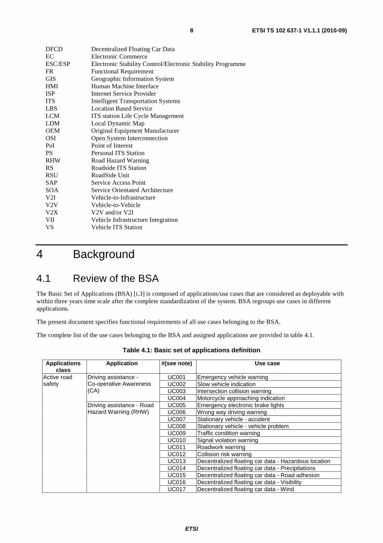
4.1 Review of the BSA The Basic Set of Applications (BSA) [i.3] is composed of applications/use cases that are considered as deployable with within three years time scale after the complete standardization of the system. BSA regroups use cases in different applications.
The present document specifies functional requirements of all use cases belonging to the BSA.
The complete list of the use cases belonging to the BSA and assigned applications are provided in table 4.1.
Table 4.1: Basic set of applications definition
Applications class
Application #(see note) Use case
Active road safety
Driving assistance - Co-operative Awareness (CA)
UC001 Emergency vehicle warning UC002 Slow vehicle indication UC003 Intersection collision warning UC004 Motorcycle approaching indication
Driving assistance - Road Hazard Warning (RHW)
UC005 Emergency electronic brake lights UC006 Wrong way driving warning UC007 Stationary vehicle - accident UC008 Stationary vehicle - vehicle problem UC009 Traffic condition warning UC010 Signal violation warning UC011 Roadwork warning UC012 Collision risk warning UC013 Decentralized floating car data - Hazardous location UC014 Decentralized floating car data - Precipitations UC015 Decentralized floating car data - Road adhesion UC016 Decentralized floating car data - Visibility UC017 Decentralized floating car data - Wind
ETSI
ETSI TS 102 637-1 V1.1.1 (2010-09)9
Applications class
Application #(see note) Use case
Co-operative traffic efficiency
Speed Management (CSM)
UC018 Regulatory/contextual speed limits notification UC019 Traffic light optimal speed advisory
Co-operative Navigation (CoNa)
UC020 Traffic information and recommended itinerary UC021 Enhanced route guidance and navigation UC022 Limited access warning and detour notification UC023 In-vehicle signage
Co-operative local services
Location Based Services (LBS)
UC024 Point of Interest notification UC025 Automatic access control and parking management UC026 ITS local electronic commerce UC027 Media downloading
Global internet services
Communities sServices (ComS)
UC028 Insurance and financial services UC029 Fleet management UC030 Loading zone management
ITS station Life Cycle Management (LCM)
UC031 Vehicle software/data provisioning and update UC032 Vehicle and RSU data calibration
NOTE: The identifier of the use case is defined and used only within the present document.
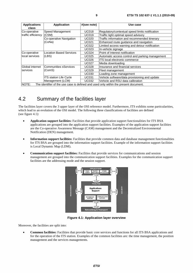
4.2 Summary of the facilities layer The facilities layer covers the 3 upper layer of the OSI reference model. Furthermore, ITS exhibits some particularities, which lead to an evolution of the OSI model. The following three classifications of facilities are defined (see figure 4.1):
• Application support facilities: Facilities that provide application support functionalities for ITS BSA applications are grouped into the application support facilities. Examples of the application support facilities are the Co-operative Awareness Message (CAM) management and the Decentralized Environmental Notification (DEN) management.
• Information support facilities: Facilities that provide common data and database management functionalities for ITS BSA are grouped into the information support facilities. Example of the information support facilities is Local Dynamic Map (LDM).
• Communication support facilities: Facilities that provide services for communications and session management are grouped into the communication support facilities. Examples for the communication support facilities are the addressing mode and the session support.
Figure 4.1: Application layer overview
Moreover, the facilities are split into:
• Common facilities: Facilities that provide basic core services and functions for all ITS BSA applications and for the operation of the ITS station. Examples of the common facilities are: the time management, the position management and the services managements.
ETSI
ETSI TS 102 637-1 V1.1.1 (2010-09)10
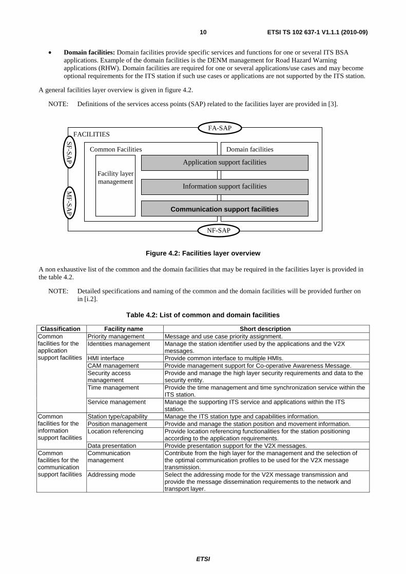
• Domain facilities: Domain facilities provide specific services and functions for one or several ITS BSA applications. Example of the domain facilities is the DENM management for Road Hazard Warning applications (RHW). Domain facilities are required for one or several applications/use cases and may become optional requirements for the ITS station if such use cases or applications are not supported by the ITS station.
A general facilities layer overview is given in figure 4.2.
NOTE: Definitions of the services access points (SAP) related to the facilities layer are provided in [3].
Figure 4.2: Facilities layer overview
A non exhaustive list of the common and the domain facilities that may be required in the facilities layer is provided in the table 4.2.
NOTE: Detailed specifications and naming of the common and the domain facilities will be provided further on in [i.2].
Table 4.2: List of common and domain facilities
Classification Facility name Short description Common facilities for the application support facilities
Priority management Message and use case priority assignment. Identities management Manage the station identifier used by the applications and the V2X
messages. HMI interface Provide common interface to multiple HMIs. CAM management Provide management support for Co-operative Awareness Message. Security access management
Provide and manage the high layer security requirements and data to the security entity.
Time management Provide the time management and time synchronization service within the ITS station.
Service management Manage the supporting ITS service and applications within the ITS station.
Common facilities for the information support facilities
Station type/capability Manage the ITS station type and capabilities information. Position management Provide and manage the station position and movement information. Location referencing Provide location referencing functionalities for the station positioning
according to the application requirements. Data presentation Provide presentation support for the V2X messages.
Common facilities for the communication support facilities
Communication management
Contribute from the high layer for the management and the selection of the optimal communication profiles to be used for the V2X message transmission.
Addressing mode Select the addressing mode for the V2X message transmission and provide the message dissemination requirements to the network and transport layer.
FACILITIES
Domain facilities Common Facilities
Application support facilities
Information support facilities
Communication support facilities
Facility layer management
FA-SAP
NF-SAP
MF-SA
P
SF-SAP

ETSI
ETSI TS 102 637-1 V1.1.1 (2010-09)11
Classification Facility name Short description Domain facilities for the application support facilities
Mobile station dynamics Manage the vehicle ITS station dynamics information from the in vehicle networks and vehicle electronic functions.
Mobile station status monitoring
Monitor mobile station status from in vehicle network and vehicle electronic functions and provide information for applications.
DENM management Manage DENM and DENM protocol. Roadside ITS station state monitoring
Monitors the roadside ITS station status.
Client ID management Manage and define the service clients profile information. Web service High layer protocols for the web service e.g. SOA application protocol
support. Billing and payment Provide service access to the billing and payment service. GIS support Provide the interface to the GIS service. Discovery mechanism Discover the users of a community service either by a service
announcement (passive) or by a subscription (active). Station life cycle management
Provide the support for station software updating and data updating.
Relevance check Provide the relevance check for the received information from other ITS stations, according to the application requirements.
Domain facilities for the information support facilities
LDM LDM database. Map data base Provide interface to the map data base at the central ITS station. Service content database Manage a database of the ITS service content. RSU registration Manage the roadside ITS stations and their information that are under the
control of a central ITS station. User repository Management of the user information at a central ITS station providing an
ITS service. Fleet Monitoring Monitor the community service behaviour at the central ITS station
relevant. Message queuing Manage the V2X messages queuing based on the message priority and
the client services/use case requirements. Domain facility for communication support facilities
Session support Support the communication session establishment and closure.
4.3 Methodology The present technical specifications identify the application general functional requirements and the use case specific functional requirements at the involved ITS stations for BSA application/use case. Two types of functional requirements are defined:
• Application functional requirements: A general functional requirement for an application. An application functional requirement applies to all use cases belonging to this application. Application functional requirements are denoted as [FR_application_#_stationtype], where:
- FR indicates the term Functional Requirement;
- application provides the application acronym as defined in table 4.1 to which the functional requirement applies;
- # indicates a sequence number assigned to this functional requirement;
- ITS station type indicates the type of the ITS station that the functional requirement is relevant to. This field may be missing if the corresponding requirement does not apply to any specific ITS station type.
• Use case functional requirements: A functional requirement for a use case. A use case functional requirement is specific to the use case and do not apply to other use cases belonging to the same application neither to the use cases belonging to the other applications. Use case functional requirements are denoted as [FR_UC#_#_stationtype], where:
- FR indicates the term functional requirement;
- UC# provides the use case number as defined in table 4.1 to which this functional requirement applies;
ETSI
ETSI TS 102 637-1 V1.1.1 (2010-09)12
- # indicates a sequence number assigned to this functional requirement;
- station type indicates the type of the ITS station that the functional requirement is relevant to. This field may be missing if the corresponding requirement does not apply to any specific ITS station type.
ITS station types are as defined in [3], namely:
• Central ITS station: Central ITS station provides the centralized BSA ITS applications. A central station may play the role of a traffic operator, road operator, services provider or content provider. Central ITS station may require further connection with a backend system if required by the use case.
NOTE 1: The information exchanged and communication between a central ITS station and a backend system is not specified in the present document.
NOTE 2: For the numeration of the functional requirement, central ITS station is denoted as CS in the present document.
• Roadside ITS station: Roadside ITS station provides ITS applications from roadside. A roadside station may provide ITS applications independently or co-operatively with the central ITS station or other roadside ITS stations.
NOTE 3: For the numeration of the functional requirement, roadside ITS station is denoted as RS in the present document.
• Vehicle ITS station: Vehicle ITS station provides ITS applications to drivers and/or passengers. It may require an interface to access in vehicle data from the in vehicle network or in vehicle system e.g. CAN.
NOTE 4: For the numeration of the functional requirement, vehicle ITS station is denoted as VS in the present document.
• Personal ITS station: ITS personal station provides ITS application to personal and nomadic devices.
NOTE 5: For the numeration of the functional requirement, personal ITS station is denoted as PS in the present document.
5 V2X communication scenarios and V2X messages content requirements
ITS applications are distributed among ITS stations that can be equipped with multiple communication capabilities. The communications are achieved through exchanged V2X messages using multiple communication protocol stacks as defined in [i.1].
Communication scenarios that shall be supported by the GeoNetworking are as defined in [4].
For other communication protocol stacks as defined in [i.1], the following communication scenarios are required for the BSA:
• point-to-point: communication from an ITS station to another ITS station. This includes the point to pint communication and point-to-point session between the two ITS stations;
• point-to-multipoint: communication from an ITS station to multiple ITS stations.
ETSI
ETSI TS 102 637-1 V1.1.1 (2010-09)13
5.1 Active road safety
5.1.1 Driving assistance - Co-operative awareness
The driving assistance co-operative awareness application is using broadcasted CAMs. If required by the use case, it uses complementary DENMs.
The CAM is specified in [1].
The DENM format and content is specified in [2].
5.1.2 Driving assistance - Road Hazard Warning
The driving assistance RHW application is using the DENMs.
The DENM format and content is specified in [2].
5.2 Co-operative traffic efficiency The co-operative traffic efficiency application provides traffic information to road users from a roadside ITS station to vehicle ITS stations or personal ITS stations. Furthermore, the co-operative traffic efficiency application may require communications between a roadside ITS station and a central ITS station.
The co-operative traffic efficiency application may make use of the co-operative road safety information as introduced in clause 5.1. In such case, two possibilities exist:
• A roadside ITS station receives the CAMs and DENMs from other ITS stations, it forwards the received information directly to the central ITS station by a point-to-point communication.
• A roadside ITS station receives the CAM and DENM, it locally pre-process the received V2X messages. The results of the processing and the aggregated information are transmitted to the central ITS station via point-to-point communication.
A co-operative traffic efficiency application may be initiated directly from a roadside ITS station that provides the information to road users by transmitting V2X messages. Alternatively, a cooperativge traffic efficiency application may be initiated by a central ITS station, which provides information related to the application to a roadside ITS station, the roadside ITS station process this information and transmits the V2X messages to road users. Two communication scenarios exist:
• For communications between the roadside ITS station and the vehicle ITS stations or personal ITS stations, the communication can be based on geobroadcast from the roadside ITS station to vehicles or personal ITS stations within a specific area, or on point-to-point communication between a roadside ITS station and a specific vehicle or personal ITS station.
• For communication between the roadside ITS station and the central ITS station, the communication is established for necessary roadside ITS station or ITS application control actions, e.g. application updates, traffic management data updates etc. Point-to-point communication is used for this purpose.
The roadside ITS station is authorized to provide traffic management information to road users. Co-operative traffic efficiency applications should be announced by the roadside ITS station that is providing the associated use cases or services.
ETSI
ETSI TS 102 637-1 V1.1.1 (2010-09)14
5.2.1 Speed management - Regulatory/contextual speed limits notification
Co-operative speed management - regulatory/contextual speed limits notification should be announced by the roadside ITS station that is providing the associated service by the service announcement functionality.
A "speed limit notification" V2X message is broadcasted by an authorized roadside ITS station. The "speed limit notification" V2X message transmission is activated and terminated by the roadside ITS station, or if necessary under the control by a central ITS station. All capable vehicle ITS stations located in the required transmission area should receive the "speed limit notification" V2X message. Geobroadcast is used for the "speed limit notification" V2X message transmission.
Once the broadcasting has been started, it continues at a given frequency during a programmed time period. This continuous process also allows a "speed limit notification" V2X message to include the updated speed limit information.
As an example of the transmitted information, a "speed limit notification" V2X message may contain the current regulatory speed limit, one or several recommended contextual speed(s) limit(s). Associated context(s), e.g. for echo routing, for traffic management, for safety etc may be provided as well in association with the speed limit. The use case is required to provide the relevance area for this speed limit information in terms of the geographical coverage and the traffic heading.
5.2.2 Speed management - Traffic light optimal speed advisory
Necessary services for the "traffic green light optimal speed advisory" should be announced by the roadside ITS station that is providing the associated services by the service announcement functionality.
A roadside ITS station may provide information about the signal phase and timing in a "signal phase and timing" V2X message and the intersection topology information in an "intersection topology" V2X message to vehicle ITS stations. The "signal phase and timing" V2X message and the "intersection topology" V2X messages are broadcasted by an authorized roadside ITS station. The broadcasting can be activated and terminated by the roadside ITS station, if necessary under the control by a central ITS station. All vehicle ITS stations located in the required transmission area should receive the V2X messages. Geobroadcast is used for the V2X messages transmission.
Once the broadcasting has been started, it continues at a given frequency. This continuous process also allows the "signal phase and timing" V2X message to include the updated traffic light phase and timing information.
As an example of the transmitted information, a signal phase and timing V2X message may contain the current traffic light phases (green, yellow or red), e.g. one per controlled lane, the remaining time before phases changes, the duration of each phase. An intersection topology V2X messages should contain the relevant road sections or geographical areas per road sign, the geometry and positions of the stop lines.
5.2.3 Co-operative navigation
Necessary services on the "co-operative navigation" shall be announced by the roadside ITS station that is providing the associated service by the service announcement functionality.
A "co-operative navigation" V2X messages can be broadcasted by an authorized roadside ITS station. The broadcasting can be activated and terminated by the roadside ITS station, if necessary under the control by a central ITS station. All vehicle ITS stations present in the required transmission area should receive the broadcasted "co-operative navigation" V2X messages. Geobroadcasting is used for this V2X message transmission.
Once the broadcasting has been started, it continues at a given frequency. This continuous process also allows the "co-operative navigation" V2X message to include the updated navigation information.
As example of the transmitted information, a "co-operative navigation" V2X message may contain a definition of the navigation information valid area, some circulation constraints information, some recommended itineraries (waypoints) and other recommendations information, etc. It may contain as well local traffic information, etc.

ETSI
ETSI TS 102 637-1 V1.1.1 (2010-09)15
5.3 Co-operative local services
5.3.1 Location based services - point of Interest notification
Necessary services on the "Point of Interest (PoI) notification" shall be announced by an authorized roadside ITS station that is providing the associated service.
A "PoI notification" V2X message is broadcasted by an authorized roadside ITS station. The broadcasting is activated by the roadside ITS station when e.g. one vehicle ITS station is requesting it or under the control of the central ITS station. However, all other capable vehicle ITS stations located in the required transmission area has the possibility to receive the broadcasted "PoI notification" V2X messages without having the need to request it. Geobroadcasting or point to multi-point communication may be used for the "PoI notification" V2X message transmission.
Once the broadcasting has been started, it continues at a given frequency during a programmed time period. This continuous process also allows the "PoI notification" V2X message to include dynamic PoI notification information.
As an example of the transmitted information, a "PoI notification V2X" messages may contain the number of PoIs being announced, their positions, types and relevant associated dynamic information related to each PoI.
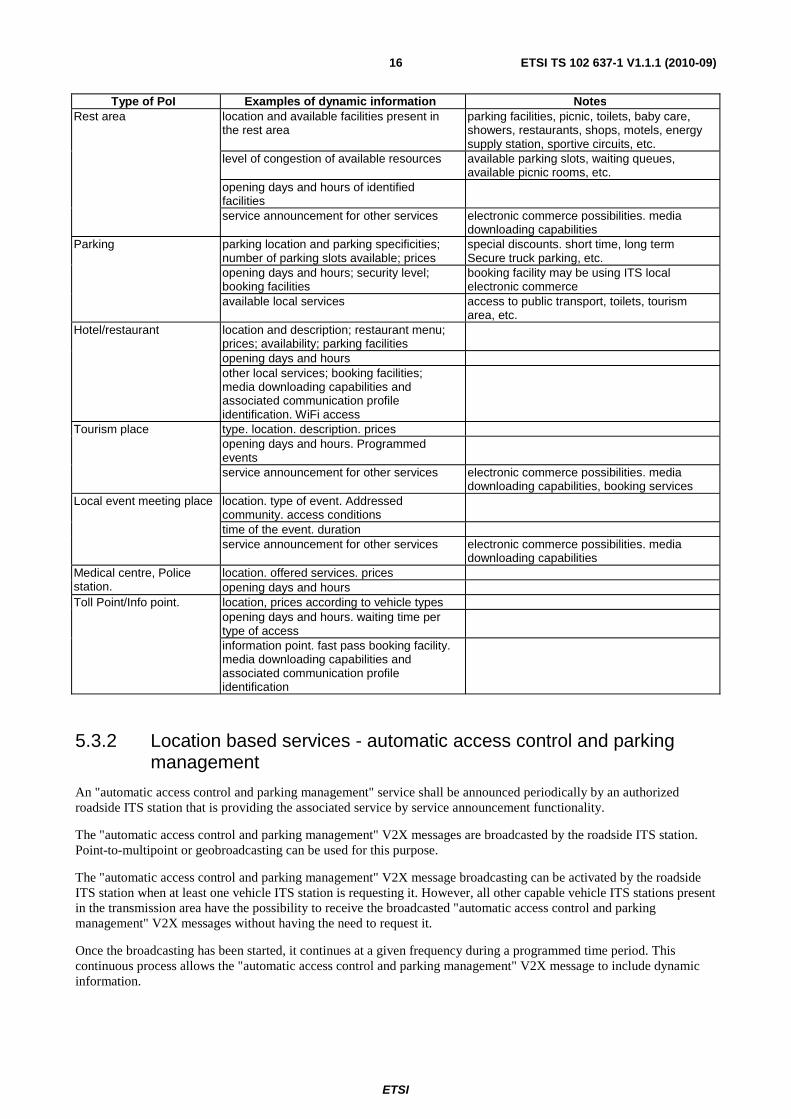
A summary of the PoIs being considered in BSA with some example of dynamic information are provided in table 5.
Table 5.1: Non exhaustive examples of point of interest with dynamic information
Type of PoI Examples of dynamic information Notes Vehicles energy supply station
location and types of available energies and associated waiting times
fuel, electrical charging facilities and charging time, diesel, battery replacement
energies prices opening time and days service announcement for other services electronic commerce possibilities; media
downloading capabilities other services and facilities toilets, shop, baby care, booking facilities, etc.
booking facility Vehicle maintenance facility/vehicle testing centre
location and type of vehicle maintenance; time and associated cost for elementary maintenance operations
opening days and hours service announcement for other services electronic commerce possibilities; media
downloading capabilities other services and facilities toilets, shop, booking facilities
Public transport management
type of managed public transport addressing to a specific community
exchanging instructions and reports expected delays, security problems, vehicle problem, etc.
service announcement for other services electronic commerce possibilities; media downloading capabilities
instant personalized messages instant message addressed to driver of the targeted public transport
Public transport gathering location and dynamic timetable of transport vehicles at the gathering point
capacity information number of available rooms and special facilities offered by the incoming vehicles
parking facilities at proximity number of available slots, prices, security level
prices and special offers; booking facilities booking facility may be using ITS local electronic commerce
ETSI
ETSI TS 102 637-1 V1.1.1 (2010-09)16
Type of PoI Examples of dynamic information Notes Rest area location and available facilities present in
the rest area parking facilities, picnic, toilets, baby care, showers, restaurants, shops, motels, energy supply station, sportive circuits, etc.
level of congestion of available resources available parking slots, waiting queues, available picnic rooms, etc.
opening days and hours of identified facilities
service announcement for other services electronic commerce possibilities. media downloading capabilities
Parking parking location and parking specificities; number of parking slots available; prices
special discounts. short time, long term Secure truck parking, etc.
opening days and hours; security level; booking facilities
booking facility may be using ITS local electronic commerce
available local services access to public transport, toilets, tourism area, etc.
Hotel/restaurant location and description; restaurant menu; prices; availability; parking facilities
opening days and hours other local services; booking facilities; media downloading capabilities and associated communication profile identification. WiFi access
Tourism place type. location. description. prices opening days and hours. Programmed events
service announcement for other services electronic commerce possibilities. media downloading capabilities, booking services
Local event meeting place location. type of event. Addressed community. access conditions
time of the event. duration service announcement for other services electronic commerce possibilities. media
downloading capabilities Medical centre, Police station.
location. offered services. prices opening days and hours
Toll Point/Info point. location, prices according to vehicle types opening days and hours. waiting time per type of access
information point. fast pass booking facility. media downloading capabilities and associated communication profile identification
5.3.2 Location based services - automatic access control and parking management
An "automatic access control and parking management" service shall be announced periodically by an authorized roadside ITS station that is providing the associated service by service announcement functionality.
The "automatic access control and parking management" V2X messages are broadcasted by the roadside ITS station. Point-to-multipoint or geobroadcasting can be used for this purpose.
The "automatic access control and parking management" V2X message broadcasting can be activated by the roadside ITS station when at least one vehicle ITS station is requesting it. However, all other capable vehicle ITS stations present in the transmission area have the possibility to receive the broadcasted "automatic access control and parking management" V2X messages without having the need to request it.
Once the broadcasting has been started, it continues at a given frequency during a programmed time period. This continuous process allows the "automatic access control and parking management" V2X message to include dynamic information.
ETSI
ETSI TS 102 637-1 V1.1.1 (2010-09)17
As an example of the transmitted information, an "automatic access control and parking management" V2X message may contain the dynamic information required for a driver to decide or not to park, including:
• parking precise location;
• access conditions;
• opening days and hours;
• parking prices and currently available slots;
• payment conditions. possibility to reserve a slot;
• vehicles restrictions;
• local other facilities and services;
• etc.
Depending on the parking service procedure, a further point-to-point communication may be required between the roadside ITS station and the vehicle ITS station in order to exchange required information such as: identification of the user profile, user identity verification, access right conformation, parking data recording etc.
5.3.3 Location based services - ITS local electronic commerce
ITS local electronic commerce is associated to other applications, e.g. PoI notification or parking management applications. In such case, the service announcement is associated with the service announcement of the associated applications.
ITS local electronic commerce does not always imply a transaction with a financial service e.g. bank requiring a network global access. In such case, the electronic commerce is achieved either by the billing facilities or electronic purse/wallet facilities.
Generally an ITS local electronic commerce transaction is achieved locally with the owner of an announced PoIs. In such case, a point-to-point communication session is opened between the client ITS station and the local service provider that has the authorization to receive the payment.
5.3.4 Location based services - Media downloading
Local Media downloading is associated to some other applications, e.g. PoI notification. In such case, the announcement is associated with service announcement of the associated applications.
Media data can be broadcasted if such information is free of charge or provided by the public authorities. When the media downloading is subject to payment or under the request only, its transmission is conditioned by the verification of the user access right. In this case, a point-to-point session may be opened for the achievement of the transaction.
Global media downloading requires global service accessible via Internet. In such case, it is defined in global internet services application in clause 5.4.
5.4 Global Internet services The "global internet" service shall be announced by the ITS station that provides the associated service.
For all the considered use cases, the global internet access shall be provided by the ITS station that provides the associated services.
ISP Internet access or community guest Internet access should be indicated by the service announcement.
ETSI
ETSI TS 102 637-1 V1.1.1 (2010-09)18
5.4.1 Communities services - insurance and financial services
The "communities services - insurance and financial" services may be included as a PoI notifications application providing the insurance services to the concerned communities, e.g. discount on public transport at given period of time for a pay as you drive community. However, in this section global internet services offered to a given insurance and financial community is focused.
The internet access is provided either through an internet contract with an ISP or as a guest of the community management.
The used communication profile and communication scenarios for establishing a connection to Internet can be specific to the insurance and financial service provider.
5.4.2 Communities services - fleet management
The "communities services - fleet management" services may be included as a PoI application dedicated to the related professional fleet, e.g. local intervention base of the professional fleet. However, in this section global internet services offered to a given professional fleet is focused.
The internet access is provided to the mobile vehicle occupant as for any access from its professional workstation.
The used communication profile and the communication scenarios for establishing a connection to Internet can be specific to the fleet management service provider.
5.4.3 Communities services - loading zone management
The "communities services - loading zone management" services may also be included as a PoI notification application dedicated to the logistic services. However, in this section global internet services offered to the related fleet is focused on.
The internet access is granted to the mobile vehicle occupant as for any access from its professional workstation.
The used communication profile and the communication scenarios for establishing a connection to Internet can be specific to the fleet management service provider.
5.4.4 ITS station life cycle management - vehicle software/data provisioning and update
The "ITS station life cycle management - vehicle software/data provisioning and update" service may also be included as a PoI notification application dedicated to the ITS station life cycle management, e.g. sales of some location based services. However, in this section global internet services offered to well identified vehicle ITS station configurations is focused.
The internet access is granted either through an internet contract with an ISP or as a guest of the ITS station community management.
The used communication profile and the communication scenarios for establishing a connection to Internet can be specific to the ITS station life cycle management service provider.
5.4.5 ITS station life cycle management - ITS station data calibration
The "ITS station life cycle management - ITS station data calibration" service may also be included a PoI notification application dedicated to the ITS station life cycle management, e.g. data calibration of local roadside ITS station by a local operational support ITS station. However, in this section global internet services offered to well identified ITS station configurations is focused.
The internet access is granted either through an internet contract with an ISP or as a guest of the ITS station life cycle management community management.
The used communication profile and the communication scenarios for establishing a connection to Internet can be specific to the service provider.
ETSI
ETSI TS 102 637-1 V1.1.1 (2010-09)19
6. BSA functional requirements
6.1 Driving assistance - Co-operative awareness
6.1.1 Application overview
This application is assisting vehicles drivers in their driving activities to be aware of the presence of other vehicles or situations in its vicinity such as emergency vehicle approaching, slow vehicle approaching etc. The main characteristic of this application is to make use of the periodically broadcasted CAMs sent from ITS stations. CAM is originated independently of the use cases according to [1]. The transmission of CAM is within the ITS ad hoc networks as defined in [i.1]. Additionally, an ITS station might send out complementary DENMs in order to send the situation information to the longer distance or to provide additional information related to the situation. Upon receiving CAM or DENMs, receiver ITS station judges the risk and relevance of the situation and provides corresponding warning or information to driver via HMI.
NOTE: For use cases belonging to BSA, no automatic intervention of the ITS system to the vehicle is required.
Detailed specifications of CAM are provided within [1].
The co-operative awareness application includes the four following use cases:
• UC001: Emergency vehicle warning;
• UC002: Slow vehicle indication;
• UC003: Intersection collision warning;
• UC004: Motorcycle approaching indication.
ETSI
ETSI TS 102 637-1 V1.1.1 (2010-09)20
6.1.2 Application flow diagram
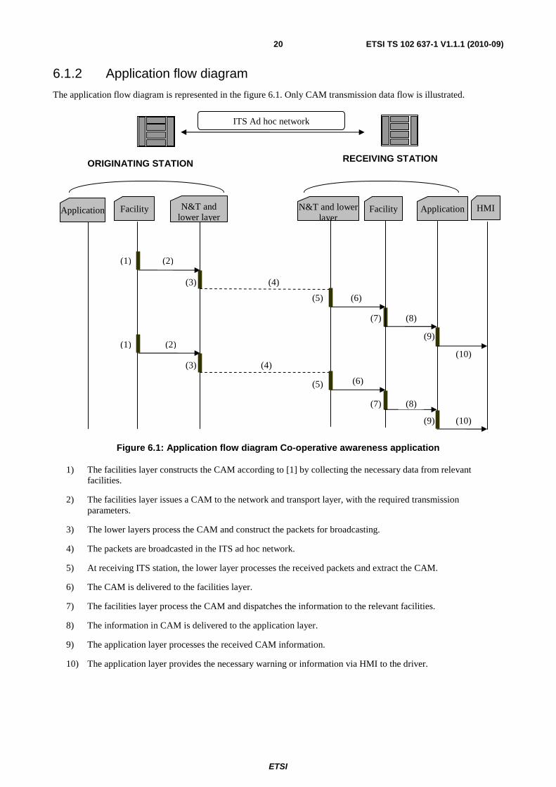
The application flow diagram is represented in the figure 6.1. Only CAM transmission data flow is illustrated.
Figure 6.1: Application flow diagram Co-operative awareness application
1) The facilities layer constructs the CAM according to [1] by collecting the necessary data from relevant facilities.
2) The facilities layer issues a CAM to the network and transport layer, with the required transmission parameters.
3) The lower layers process the CAM and construct the packets for broadcasting.
4) The packets are broadcasted in the ITS ad hoc network.
5) At receiving ITS station, the lower layer processes the received packets and extract the CAM.
6) The CAM is delivered to the facilities layer.
7) The facilities layer process the CAM and dispatches the information to the relevant facilities.
8) The information in CAM is delivered to the application layer.
9) The application layer processes the received CAM information.
10) The application layer provides the necessary warning or information via HMI to the driver.
Application
ORIGINATING STATION
Facility N&T and lower layer
(1)
(3)
N&T and lower layer
Facility Application
RECEIVING STATION
HMI
ITS Ad hoc network
(2)
(4)
(5) (6)
(7) (8)
(9)
(10) (4)
(5) (6)
(7) (8)
(9) (10)
(1) (2)
(3)
ETSI
ETSI TS 102 637-1 V1.1.1 (2010-09)21
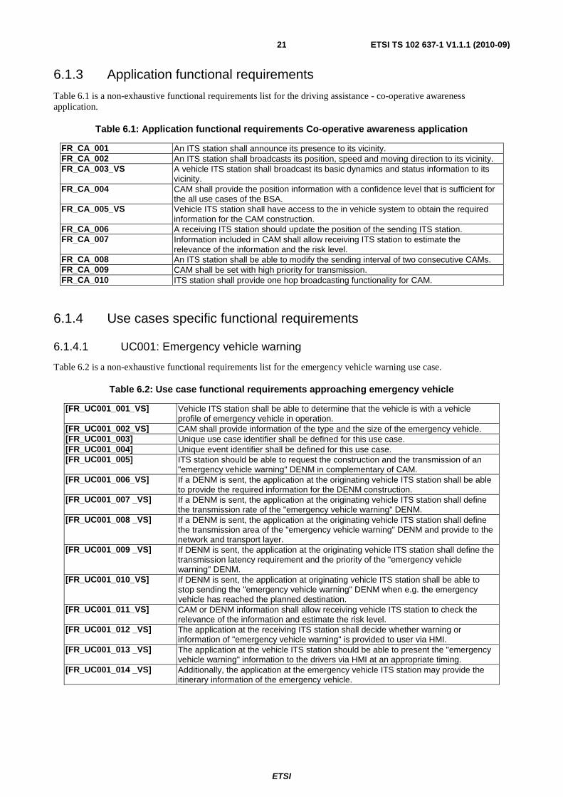
6.1.3 Application functional requirements
Table 6.1 is a non-exhaustive functional requirements list for the driving assistance - co-operative awareness application.
Table 6.1: Application functional requirements Co-operative awareness application
FR_CA_001 An ITS station shall announce its presence to its vicinity. FR_CA_002 An ITS station shall broadcasts its position, speed and moving direction to its vicinity. FR_CA_003_VS A vehicle ITS station shall broadcast its basic dynamics and status information to its
vicinity. FR_CA_004 CAM shall provide the position information with a confidence level that is sufficient for
the all use cases of the BSA. FR_CA_005_VS Vehicle ITS station shall have access to the in vehicle system to obtain the required
information for the CAM construction. FR_CA_006 A receiving ITS station should update the position of the sending ITS station. FR_CA_007 Information included in CAM shall allow receiving ITS station to estimate the
relevance of the information and the risk level. FR_CA_008 An ITS station shall be able to modify the sending interval of two consecutive CAMs. FR_CA_009 CAM shall be set with high priority for transmission. FR_CA_010 ITS station shall provide one hop broadcasting functionality for CAM.
6.1.4 Use cases specific functional requirements
6.1.4.1 UC001: Emergency vehicle warning
Table 6.2 is a non-exhaustive functional requirements list for the emergency vehicle warning use case.
Table 6.2: Use case functional requirements approaching emergency vehicle
[FR_UC001_001_VS] Vehicle ITS station shall be able to determine that the vehicle is with a vehicle profile of emergency vehicle in operation.
[FR_UC001_002_VS] CAM shall provide information of the type and the size of the emergency vehicle. [FR_UC001_003] Unique use case identifier shall be defined for this use case. [FR_UC001_004] Unique event identifier shall be defined for this use case. [FR_UC001_005] ITS station should be able to request the construction and the transmission of an
"emergency vehicle warning" DENM in complementary of CAM. [FR_UC001_006_VS] If a DENM is sent, the application at the originating vehicle ITS station shall be able
to provide the required information for the DENM construction. [FR_UC001_007 _VS] If a DENM is sent, the application at the originating vehicle ITS station shall define
the transmission rate of the "emergency vehicle warning" DENM. [FR_UC001_008 _VS] If a DENM is sent, the application at the originating vehicle ITS station shall define
the transmission area of the "emergency vehicle warning" DENM and provide to the network and transport layer.
[FR_UC001_009 _VS] If DENM is sent, the application at the originating vehicle ITS station shall define the transmission latency requirement and the priority of the "emergency vehicle warning" DENM.
[FR_UC001_010_VS] If DENM is sent, the application at originating vehicle ITS station shall be able to stop sending the "emergency vehicle warning" DENM when e.g. the emergency vehicle has reached the planned destination.
[FR_UC001_011_VS] CAM or DENM information shall allow receiving vehicle ITS station to check the relevance of the information and estimate the risk level.
[FR_UC001_012 _VS] The application at the receiving ITS station shall decide whether warning or information of "emergency vehicle warning" is provided to user via HMI.
[FR_UC001_013 _VS] The application at the vehicle ITS station should be able to present the "emergency vehicle warning" information to the drivers via HMI at an appropriate timing.
[FR_UC001_014 _VS] Additionally, the application at the emergency vehicle ITS station may provide the itinerary information of the emergency vehicle.
ETSI
ETSI TS 102 637-1 V1.1.1 (2010-09)22
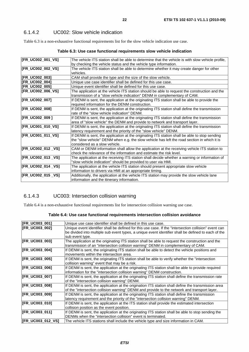
6.1.4.2 UC002: Slow vehicle indication
Table 6.3 is a non-exhaustive functional requirements list for the slow vehicle indication use case.
Table 6.3: Use case functional requirements slow vehicle indication
[FR_UC002_001_VS] The vehicle ITS station shall be able to determine that the vehicle is with slow vehicle profile, by checking the vehicle status and the vehicle type information.
[FR_UC002_002_VS] The vehicle ITS station shall be able to determine whether it may create danger for other vehicles.
[FR_UC002_003] CAM shall provide the type and the size of the slow vehicle. [FR_UC002_004] Unique use case identifier shall be defined for this use case. [FR_UC002_005] Unique event identifier shall be defined for this use case. [FR_UC002_006_VS] The application at the vehicle ITS station should be able to request the construction and the
transmission of a "slow vehicle indication" DENM in complementary of CAM. [FR_UC002_007] If DENM is sent, the application at the originating ITS station shall be able to provide the
required information for the DENM construction. [FR_UC002_008] If DENM is sent, the application at the originating ITS station shall define the transmission
rate of the "slow vehicle indication" DENM. [FR_UC002_009 ] If DENM is sent, the application at the originating ITS station shall define the transmission
area of "slow vehicle" the DENM and provide to network and transport layer. [FR_UC001_010_VS] If DENM is sent, the application at the originating ITS station shall define the transmission
latency requirement and the priority of the "slow vehicle" DENM. [FR_UC001_011_VS] If DENM is sent, the application at the originating ITS station shall be able to stop sending
the "slow vehicle" DENM when e.g. the slow vehicle has left the road section in which it is considered as a slow vehicle.
[FR_UC002_012 _VS] CAM or DENM information shall allow the application at the receiving vehicle ITS station to check the relevance of the information and estimate the risk level.
[FR_UC002_013 _VS] The application at the receiving ITS station shall decide whether a warning or information of "slow vehicle indication" should be provided to user via HMI.
[FR_UC002_014 _VS] The application at the vehicle ITS station should present appropriate slow vehicle information to drivers via HMI at an appropriate timing.
[FR_UC002_015 _VS] Additionally, the application at the vehicle ITS station may provide the slow vehicle lane information and the itinerary information.
6.1.4.3 UC003: Intersection collision warning
Table 6.4 is a non-exhaustive functional requirements list for intersection collision warning use case.
Table 6.4: Use case functional requirements intersection collision avoidance
[FR_UC003_001] Unique use case identifier shall be defined in this use case. [FR_UC003_002] Unique event identifier shall be defined for this use case. If the "intersection collision" event can
be divided into multiple sub event types, a unique event identifier shall be defined to each of the sub event type.
[FR_UC003_003] The application at the originating ITS station shall be able to request the construction and the transmission of an "intersection collision warning" DENM in complementary of CAM.
[FR_UC003_004] If DENM is sent, the originating ITS station shall be able to detect the vehicle positions and movements within the intersection area.
[FR_UC003_005] If DENM is sent, the originating ITS station shall be able to verify whether the "intersection collision warning" event that may be a risk.
[FR_UC003_006] If DENM is sent, the application at the originating ITS station shall be able to provide required information for the "intersection collision warning" DENM construction.
[FR_UC003_007] If DENM is sent, the application at the originating ITS station shall define the transmission rate of the "intersection collision warning" DENM.
[FR_UC003_008] If DENM is sent, the application at the origination ITS station shall define the transmission area of the "intersection collision warning" DENM and provide to the network and transport layer.
[FR_UC003_009] If DENM is sent, the application at the originating ITS station shall define the transmission latency requirement and the priority of the "intersection collision warning" DENM.
[FR_UC003_010] If DENM is sent, the application at the ITS station shall provide the estimated intersection collision position as the event position.
[FR_UC003_011] If DENM is sent, the application at the originating ITS station shall be able to stop sending the DENMs when the "intersection collision" event is terminated.
[FR_UC003_012_VS] The vehicle ITS stations shall include the vehicle type and size information in CAM.

ETSI
ETSI TS 102 637-1 V1.1.1 (2010-09)23
[FR_UC003_013_VS] Information in CAM or DENM shall allow the application at the receiving vehicle ITS station to check the relevance of the information and estimate the risk level.
[FR_UC003_014_VS] The application at the receiving ITS station shall decide whether a warning or information of "intersection collision" event is provided to the driver via HMI.
[FR_UC003_015_VS] The application at the vehicle ITS station should present the "intersection collision warning" to the driver via HMI at an appropriate timing.
[FR_UC003_016_VS] Additionally, the application at the vehicle ITS station may further broadcast its itinerary to pass the intersection.
6.1.4.4 C004: Motorcycle approaching indication
Table 6.5 is a non-exhaustive functional requirements list for motorcycle approaching indication use case.
Table 6.5: Use case functional requirements motorcycle approaching indication
[FR_UC004_001_VS] CAM shall include the motorcycle type information. [FR_UC004_002] Unique use case identifier shall be defined in this use case. [FR_UC004_003] Unique event identifier shall be defined for this use case. [FR_UC004_004] The application at the ITS station should be able to request the construction and the
transmission of a "motorcycle approaching" DENM in complementary of CAM. [FR_UC004_005] If DENM is sent, the application at the originating ITS station shall be able to provide the
required information for DENM construction. [FR_UC004_006] If DENM is sent, the application at the originating ITS station shall define the transmission
rate of the "motorcycle approaching" DENM. [FR_UC004_007] If DENM is sent, the application at the originating ITS station shall define the transmission
area of the "motorcycle approaching" DENM and provide to the network and transport layer. [FR_UC004_008] If DENM is sent, the application at the originating ITS station shall define the transmission
latency requirement and the priority of the "motorcycle approaching" DENM. [FR_UC004_011] If DENM is sent, the application at the originating ITS station shall provide the current
motorcycle position as the event position. [FR_UC004_012] If DENM is sent, the application at the originating ITS station shall be able to stop sending
the "motorcycle approaching" DENM when e.g. the motorcycle has passed the intersection area.
[FR_UC004_013_VS] Information included in the CAM and DENM shall allow the application at the receiving vehicle ITS station to check the relevance and to estimate the collision risk level.
[FR_UC003_014_VS] The application at the receiving ITS station shall decide whether a warning or information of "motorcycle approaching" should be provided to the driver via HMI.
[FR_UC003_015_VS] The application at the ITS station should provide appropriate HMI information to driver at an appropriate timing.
[FR_UC003_016_VS] Additionally, the application at the motorcycle ITS station may broadcast its itinerary.
6.2 Driving assistance - Road hazard warning
6.2.1 Application overview Road hazard warning (RHW) application is assisting ITS users in their driving activities by providing information on the road hazard events.
NOTE: For use cases belonging to the BSA, no automatic driving intervention of the ITS system is required.
Detected events are mainly characterized by the following properties:
• The event position: an event can be either at a specific location or covers a geographic region or road sections. The event can be moving or static.
• Duration: an event duration may vary from e.g. several minutes to several days or months.
• Severity: the safety impact on road safety or traffic efficiency caused by the event.
• Evolution: an event may evolve both in time and in space.

ETSI
ETSI TS 102 637-1 V1.1.1 (2010-09)24
This application is characterized by the usage of the Decentralized Environmental Notification (DEN) basic service and the dissemination of the DENMs. The DEN basic service is a set of application component and facilities that are required for the RHW use case development and execution. The specific DENM management rules are under the responsibility of the DEN basic service. In particular, DEN basic service includes the following main components and functionalities:
• DENM management: construction and management of DENMs.
• RHW application: a RHW use case requires a close interaction between the application layer and the facilities layer. A RHW application component specific to the RHW use case is included in the DEN basic service. The main functionalities of a RHW application includes the detection of the event , initiation and termination of the DENM broadcasting, definition of the use case specific information needed by the construction of DENM message and the DENM dissemination, in particular:
- the event type;
- the event location;
- the transmission area of the DENM;
- the event duration, which can be an estimated or predefined duration for the event;
- the DENM transmission rate;
- the updating of the event evolution in the updated DENM.
• LDM: management of the event in the LDM database.
The purpose of the RHW application is to improve the road safety, the dissemination of the DENMs for the RHW application is mainly realized in the ITS ad hoc networks. Furthermore, RHW application can provide information for the traffic management purpose related to road hazards. For such purpose, communication with central ITS station may be established to inform the detected event so that the corresponding rescues or other traffic management measures are taken.
A DENM can be updated if the evolution of the event is detected. Communication systems of the ITS stations should be capable of keeping a DENM alive inside the relevance area, as long as the the DENM is still valid, even though the originator ITS station of the DENM has stopped sending DENMs or has moved away from the event position. The termination of the event is either triggered by the originator ITS station by sending a specific version of DENM (cancellation DENM) or by an authorized third part ITS stations by sending a negation DENM. The updated DENM, cancellation DENM and the negation DENM shall be referenced to the DENMs that have been previously sent.
Upon the reception of a DENM, an ITS station analyzes if it is concerned by the event and provides corresponding information or warning to the road user via HMI.
Detailed specifications of the DEN basic service and DENM are defined in [2].
The following use cases are considered in BSA:
• UC005: emergency electronic brake lights;
• UC006: wrong way driving warning;
• UC007: stationary vehicle warning - accident;
• UC008: stationary vehicle warning - vehicle problem;
• UC009: traffic condition warning;
• UC010: signal violation warning;
• UC011: roadwork warning;
• UC012: collision risk warning;
• UC013: decentralized floating car data - hazardous location;
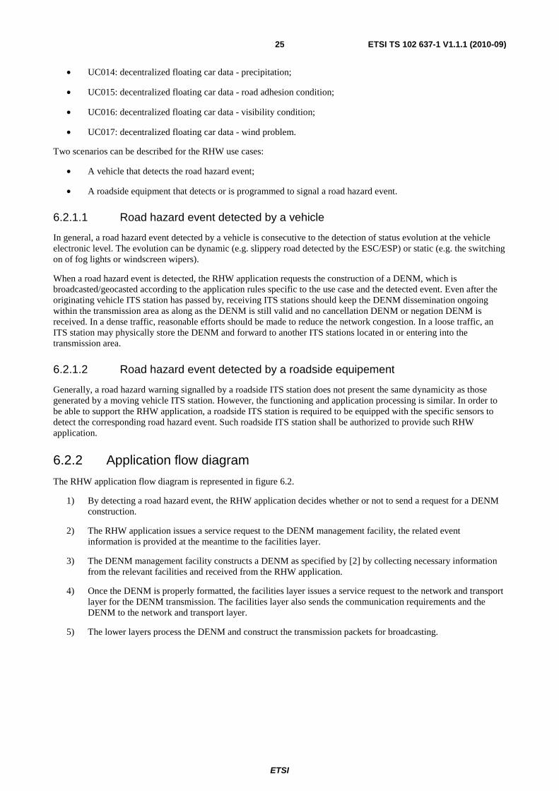
ETSI
ETSI TS 102 637-1 V1.1.1 (2010-09)25
• UC014: decentralized floating car data - precipitation;
• UC015: decentralized floating car data - road adhesion condition;
• UC016: decentralized floating car data - visibility condition;
• UC017: decentralized floating car data - wind problem.
Two scenarios can be described for the RHW use cases:
• A vehicle that detects the road hazard event;
• A roadside equipment that detects or is programmed to signal a road hazard event.
6.2.1.1 Road hazard event detected by a vehicle
In general, a road hazard event detected by a vehicle is consecutive to the detection of status evolution at the vehicle electronic level. The evolution can be dynamic (e.g. slippery road detected by the ESC/ESP) or static (e.g. the switching on of fog lights or windscreen wipers).
When a road hazard event is detected, the RHW application requests the construction of a DENM, which is broadcasted/geocasted according to the application rules specific to the use case and the detected event. Even after the originating vehicle ITS station has passed by, receiving ITS stations should keep the DENM dissemination ongoing within the transmission area as along as the DENM is still valid and no cancellation DENM or negation DENM is received. In a dense traffic, reasonable efforts should be made to reduce the network congestion. In a loose traffic, an ITS station may physically store the DENM and forward to another ITS stations located in or entering into the transmission area.
6.2.1.2 Road hazard event detected by a roadside equipement
Generally, a road hazard warning signalled by a roadside ITS station does not present the same dynamicity as those generated by a moving vehicle ITS station. However, the functioning and application processing is similar. In order to be able to support the RHW application, a roadside ITS station is required to be equipped with the specific sensors to detect the corresponding road hazard event. Such roadside ITS station shall be authorized to provide such RHW application.
6.2.2 Application flow diagram
The RHW application flow diagram is represented in figure 6.2.
1) By detecting a road hazard event, the RHW application decides whether or not to send a request for a DENM construction.
2) The RHW application issues a service request to the DENM management facility, the related event information is provided at the meantime to the facilities layer.
3) The DENM management facility constructs a DENM as specified by [2] by collecting necessary information from the relevant facilities and received from the RHW application.
4) Once the DENM is properly formatted, the facilities layer issues a service request to the network and transport layer for the DENM transmission. The facilities layer also sends the communication requirements and the DENM to the network and transport layer.
5) The lower layers process the DENM and construct the transmission packets for broadcasting.
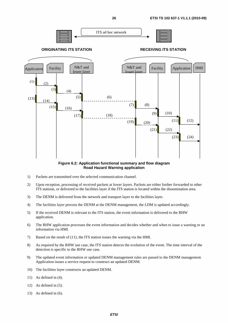
ETSI
ETSI TS 102 637-1 V1.1.1 (2010-09)26
Figure 6.2: Application functional summary and flow diagram Road Hazard Warning application
1) Packets are transmitted over the selected communication channel.
2) Upon reception, processing of received packets at lower layers. Packets are either further forwarded to other ITS stations, or delivered to the facilities layer if the ITS station is located within the dissemination area.
3) The DENM is delivered from the network and transport layer to the facilities layer.
4) The facilities layer process the DENM at the DENM management, the LDM is updated accordingly.
5) If the received DENM is relevant to the ITS station, the event information is delivered to the RHW application.
6) The RHW application processes the event information and decides whether and when to issue a warning or an information via HMI.
7) Based on the result of (11), the ITS station issues the warning via the HMI.
8) As required by the RHW use case, the ITS station detects the evolution of the event. The time interval of the detection is specific to the RHW use case.
9) The updated event information or updated DENM management rules are passed to the DENM management. Application issues a service request to construct an updated DENM.
10) The facilities layer constructs an updated DENM.
11) As defined in (4).
12) As defined in (5).
13) As defined in (6).
Application
ORIGINATING ITS STATION
Facility N&T and lower layer
(1)
(3)
N&T and lower layer
Facility Application
RECEIVING ITS STATION
HMI
ITS ad hoc network
(2)
(4)
(6)
(7) (8)
(9) (10)
(11) (12)
(14)
(16) (15)
(17) (18)
(19) (20)
(21) (22)
(23) (24)
(5)(13)
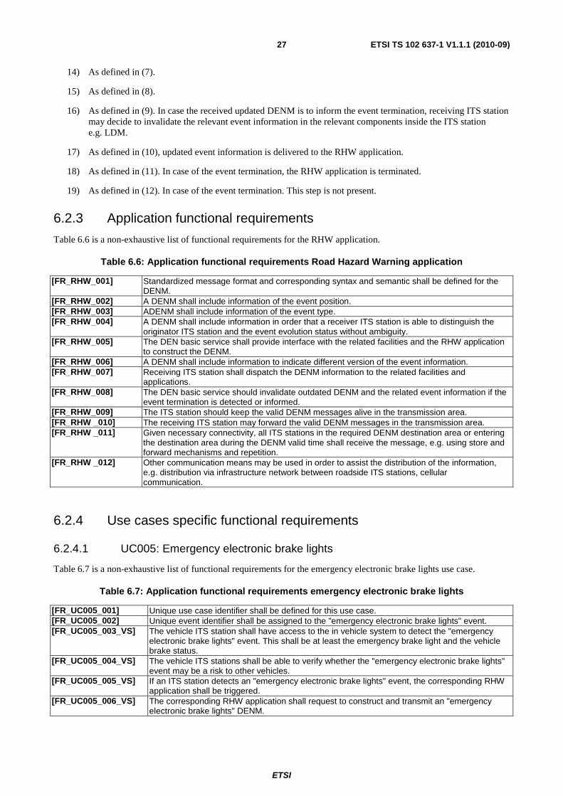
ETSI
ETSI TS 102 637-1 V1.1.1 (2010-09)27
14) As defined in (7).
15) As defined in (8).
16) As defined in (9). In case the received updated DENM is to inform the event termination, receiving ITS station may decide to invalidate the relevant event information in the relevant components inside the ITS station e.g. LDM.
17) As defined in (10), updated event information is delivered to the RHW application.
18) As defined in (11). In case of the event termination, the RHW application is terminated.
19) As defined in (12). In case of the event termination. This step is not present.
6.2.3 Application functional requirements
Table 6.6 is a non-exhaustive list of functional requirements for the RHW application.
Table 6.6: Application functional requirements Road Hazard Warning application
[FR_RHW_001] Standardized message format and corresponding syntax and semantic shall be defined for the DENM.
[FR_RHW_002] A DENM shall include information of the event position. [FR_RHW_003] ADENM shall include information of the event type. [FR_RHW_004] A DENM shall include information in order that a receiver ITS station is able to distinguish the
originator ITS station and the event evolution status without ambiguity. [FR_RHW_005] The DEN basic service shall provide interface with the related facilities and the RHW application
to construct the DENM. [FR_RHW_006] A DENM shall include information to indicate different version of the event information. [FR_RHW_007] Receiving ITS station shall dispatch the DENM information to the related facilities and
applications. [FR_RHW_008] The DEN basic service should invalidate outdated DENM and the related event information if the
event termination is detected or informed. [FR_RHW_009] The ITS station should keep the valid DENM messages alive in the transmission area. [FR_RHW _010] The receiving ITS station may forward the valid DENM messages in the transmission area. [FR_RHW _011] Given necessary connectivity, all ITS stations in the required DENM destination area or entering
the destination area during the DENM valid time shall receive the message, e.g. using store and forward mechanisms and repetition.
[FR_RHW _012] Other communication means may be used in order to assist the distribution of the information, e.g. distribution via infrastructure network between roadside ITS stations, cellular communication.
6.2.4 Use cases specific functional requirements
6.2.4.1 UC005: Emergency electronic brake lights
Table 6.7 is a non-exhaustive list of functional requirements for the emergency electronic brake lights use case.
Table 6.7: Application functional requirements emergency electronic brake lights
[FR_UC005_001] Unique use case identifier shall be defined for this use case. [FR_UC005_002] Unique event identifier shall be assigned to the "emergency electronic brake lights" event. [FR_UC005_003_VS] The vehicle ITS station shall have access to the in vehicle system to detect the "emergency
electronic brake lights" event. This shall be at least the emergency brake light and the vehicle brake status.
[FR_UC005_004_VS] The vehicle ITS stations shall be able to verify whether the "emergency electronic brake lights" event may be a risk to other vehicles.
[FR_UC005_005_VS] If an ITS station detects an "emergency electronic brake lights" event, the corresponding RHW application shall be triggered.
[FR_UC005_006_VS] The corresponding RHW application shall request to construct and transmit an "emergency electronic brake lights" DENM.
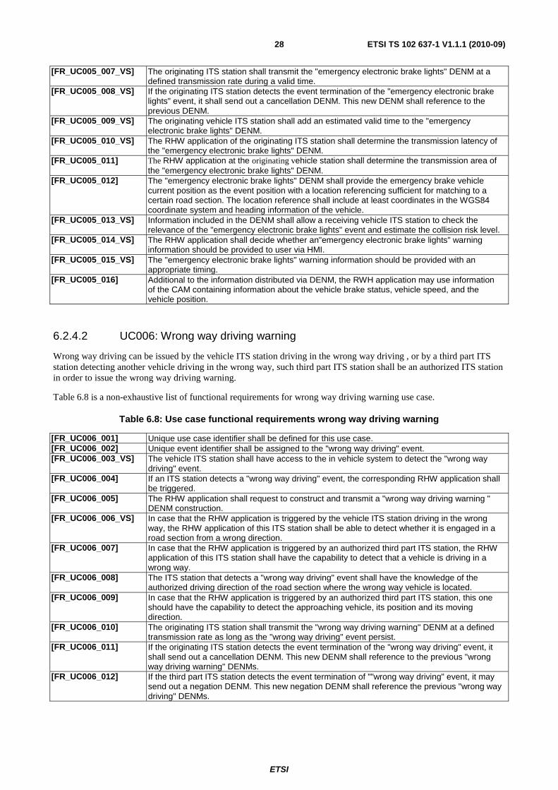
ETSI
ETSI TS 102 637-1 V1.1.1 (2010-09)28
[FR_UC005_007_VS] The originating ITS station shall transmit the "emergency electronic brake lights" DENM at a defined transmission rate during a valid time.
[FR_UC005_008_VS] If the originating ITS station detects the event termination of the "emergency electronic brake lights" event, it shall send out a cancellation DENM. This new DENM shall reference to the previous DENM.
[FR_UC005_009_VS] The originating vehicle ITS station shall add an estimated valid time to the "emergency electronic brake lights" DENM.
[FR_UC005_010_VS] The RHW application of the originating ITS station shall determine the transmission latency of the "emergency electronic brake lights" DENM.
[FR_UC005_011] The RHW application at the originating vehicle station shall determine the transmission area of the "emergency electronic brake lights" DENM.
[FR_UC005_012] The "emergency electronic brake lights" DENM shall provide the emergency brake vehicle current position as the event position with a location referencing sufficient for matching to a certain road section. The location reference shall include at least coordinates in the WGS84 coordinate system and heading information of the vehicle.
[FR_UC005_013_VS] Information included in the DENM shall allow a receiving vehicle ITS station to check the relevance of the "emergency electronic brake lights" event and estimate the collision risk level.
[FR_UC005_014_VS] The RHW application shall decide whether an"emergency electronic brake lights" warning information should be provided to user via HMI.
[FR_UC005_015_VS] The "emergency electronic brake lights" warning information should be provided with an appropriate timing.
[FR_UC005_016] Additional to the information distributed via DENM, the RWH application may use information of the CAM containing information about the vehicle brake status, vehicle speed, and the vehicle position.
6.2.4.2 UC006: Wrong way driving warning
Wrong way driving can be issued by the vehicle ITS station driving in the wrong way driving , or by a third part ITS station detecting another vehicle driving in the wrong way, such third part ITS station shall be an authorized ITS station in order to issue the wrong way driving warning.
Table 6.8 is a non-exhaustive list of functional requirements for wrong way driving warning use case.
Table 6.8: Use case functional requirements wrong way driving warning
[FR_UC006_001] Unique use case identifier shall be defined for this use case. [FR_UC006_002] Unique event identifier shall be assigned to the "wrong way driving" event. [FR_UC006_003_VS] The vehicle ITS station shall have access to the in vehicle system to detect the "wrong way
driving" event. [FR_UC006_004] If an ITS station detects a "wrong way driving" event, the corresponding RHW application shall
be triggered. [FR_UC006_005] The RHW application shall request to construct and transmit a "wrong way driving warning "
DENM construction. [FR_UC006_006_VS] In case that the RHW application is triggered by the vehicle ITS station driving in the wrong
way, the RHW application of this ITS station shall be able to detect whether it is engaged in a road section from a wrong direction.
[FR_UC006_007] In case that the RHW application is triggered by an authorized third part ITS station, the RHW application of this ITS station shall have the capability to detect that a vehicle is driving in a wrong way.
[FR_UC006_008] The ITS station that detects a "wrong way driving" event shall have the knowledge of the authorized driving direction of the road section where the wrong way vehicle is located.
[FR_UC006_009] In case that the RHW application is triggered by an authorized third part ITS station, this one should have the capability to detect the approaching vehicle, its position and its moving direction.
[FR_UC006_010] The originating ITS station shall transmit the "wrong way driving warning" DENM at a defined transmission rate as long as the "wrong way driving" event persist.
[FR_UC006_011] If the originating ITS station detects the event termination of the "wrong way driving" event, it shall send out a cancellation DENM. This new DENM shall reference to the previous "wrong way driving warning" DENMs.
[FR_UC006_012] If the third part ITS station detects the event termination of ""wrong way driving" event, it may send out a negation DENM. This new negation DENM shall reference the previous "wrong way driving" DENMs.
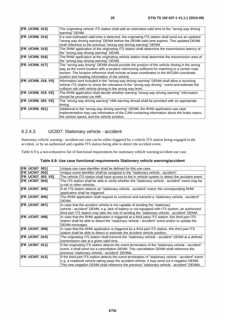
ETSI
ETSI TS 102 637-1 V1.1.1 (2010-09)29
[FR_UC006_013] The originating vehicle ITS station shall add an estimated valid time to the "wrong way driving warning" DENM.
[FR_UC006_014] If a new estimated valid time is detected, the originating ITS station shall send out an updated "wrong way driving warning" DENM before the DENM valid time expires. This updated DENM shall reference to the previous "wrong way driving warning" DENM.
[FR_UC006_015] The RHW application of the originating ITS station shall determine the transmission latency of the "wrong way driving warning" DENM.
[FR_UC006_016] The RHW application at the originating vehicle station shall determine the transmission area of the "wrong way driving warning" DENM.
[FR_UC006_017] The "wrong way driving" DENM should provide the position of the vehicle driving in the wrong way as the event location with a location referencing sufficient for matching to a certain road section. The location reference shall include at least coordinates in the WGS84 coordinate system and heading information of the vehicle.
[FR_UC006_018_VS] Information sent included in the "wrong way driving warning" DENM shall allow a receiving vehicle ITS station to check the relevance of the "wrong way driving " event and estimate the collision risk with vehicle driving in the wrong way level.
[FR_UC006_019_VS] The RHW application shall decide whether warning "wrong way driving warning" information should be provided via HMI.
[FR_UC006_020_VS] The "wrong way driving warning" HMI warning should shall be provided with an appropriate timing.
[FR_UC006_021] Additional to the "wrong way driving warning" DENM, the RHW application use case implementation may use information of the CAM containing information about the brake status, the vehicle speed, and the vehicle position.
6.2.4.3 UC007: Stationary vehicle - accident
Stationary vehicle warning - accident use case can be either triggered by a vehicle ITS station being engaged in the accident, or by an authorized and capable ITS station being able to detect the accident event.
Table 6.9 is a non-exhaustive list of functional requirements for stationary vehicle warning/accident use case.
Table 6.9: Use case functional requirements Stationary vehicle warning/accident
[FR_UC007_001] Unique use case identifier shall be defined for this use case. [FR_UC007_002] Unique event identifier shall be assigned to the "stationary vehicle - accident". [FR_UC007_003_VS] The vehicle ITS station shall have access to the in vehicle system to detect the accident event. [FR_UC007_004] The ITS station shall be able to verify whether the "stationary vehicle - accident" event may be
a risk to other vehicles. [FR_UC007_005] If an ITS station detects an "stationary vehicle - accident" event, the corresponding RHW
application shall be triggered. [FR_UC007_006] The RHW application shall request to construct and transmit a "stationary vehicle - accident"
DENM. [FR_UC007_007] In case that the accident vehicle is not capable of sending the "stationary
vehicle - accident" DENM, e.g. lack of battery or not equipped with ITS system, an authorized third part ITS station may take the role of sending the "stationary vehicle - accident" DENM.
[FR_UC007_008] In case that the RHW application is triggered at a third party ITS station, this third part ITS station shall be able to detect the "stationary vehicle - accident" event and/or to update the DENM messages.
[FR_UC007_009] In case that the RHW application is triggered by a third part ITS station, this third part ITS station shall be able to detect or estimate the accident vehicle position.
[FR_UC007_010] The originating ITS station shall transmit the "stationary vehicle - accident" DENM at a defined transmission rate at a given valid time.
[FR_UC007_011] If the originating ITS station detects the event termination of the "stationary vehicle - accident" event, it shall send out a cancellation DENM. This cancellation DENM shall reference the previous "stationary vehicle - accident" DENMs.
[FR_UC007_012] If the third part ITS station detects the event termination of "stationary vehicle - accident" event e.g. a roadwork vehicle taking away the accident vehicle, it may send out a negation DENM. This new negation DENM shall reference the previous "stationary vehicle - accident" DENMs.
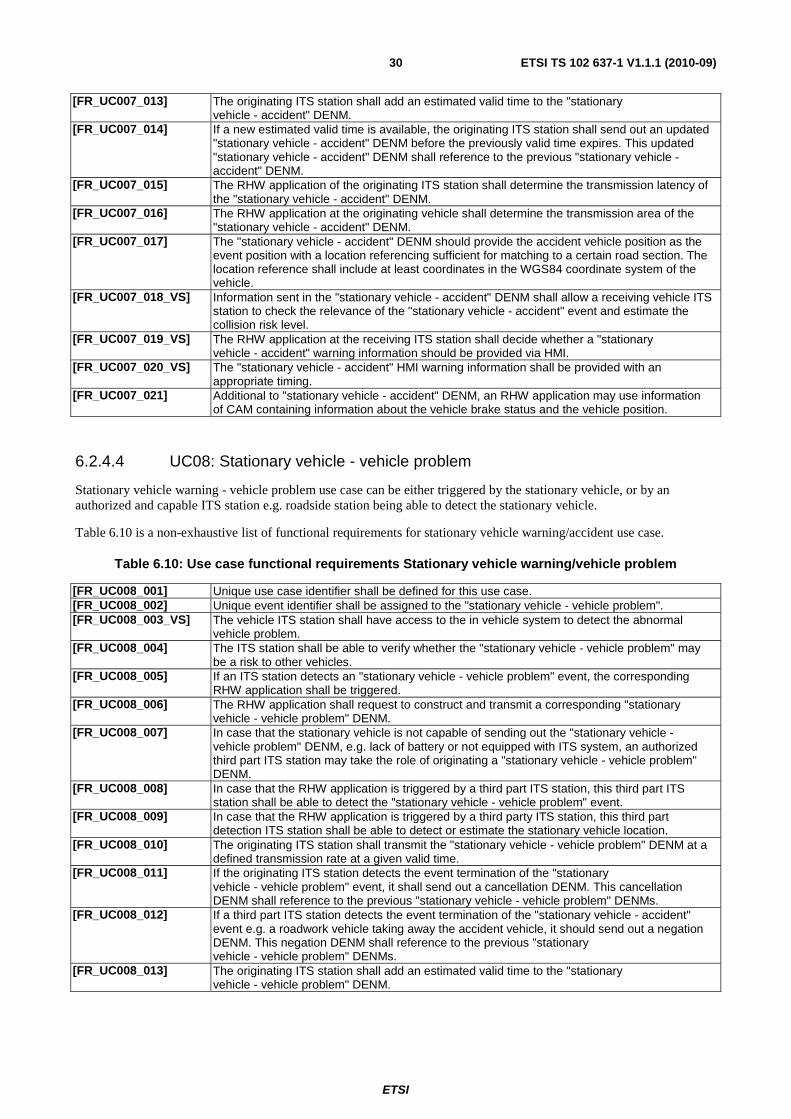
ETSI
ETSI TS 102 637-1 V1.1.1 (2010-09)30
[FR_UC007_013] The originating ITS station shall add an estimated valid time to the "stationary vehicle - accident" DENM.
[FR_UC007_014] If a new estimated valid time is available, the originating ITS station shall send out an updated "stationary vehicle - accident" DENM before the previously valid time expires. This updated "stationary vehicle - accident" DENM shall reference to the previous "stationary vehicle - accident" DENM.
[FR_UC007_015] The RHW application of the originating ITS station shall determine the transmission latency of the "stationary vehicle - accident" DENM.
[FR_UC007_016] The RHW application at the originating vehicle shall determine the transmission area of the "stationary vehicle - accident" DENM.
[FR_UC007_017] The "stationary vehicle - accident" DENM should provide the accident vehicle position as the event position with a location referencing sufficient for matching to a certain road section. The location reference shall include at least coordinates in the WGS84 coordinate system of the vehicle.
[FR_UC007_018_VS] Information sent in the "stationary vehicle - accident" DENM shall allow a receiving vehicle ITS station to check the relevance of the "stationary vehicle - accident" event and estimate the collision risk level.
[FR_UC007_019_VS] The RHW application at the receiving ITS station shall decide whether a "stationary vehicle - accident" warning information should be provided via HMI.
[FR_UC007_020_VS] The "stationary vehicle - accident" HMI warning information shall be provided with an appropriate timing.
[FR_UC007_021] Additional to "stationary vehicle - accident" DENM, an RHW application may use information of CAM containing information about the vehicle brake status and the vehicle position.
6.2.4.4 UC08: Stationary vehicle - vehicle problem
Stationary vehicle warning - vehicle problem use case can be either triggered by the stationary vehicle, or by an authorized and capable ITS station e.g. roadside station being able to detect the stationary vehicle.
Table 6.10 is a non-exhaustive list of functional requirements for stationary vehicle warning/accident use case.
Table 6.10: Use case functional requirements Stationary vehicle warning/vehicle problem
[FR_UC008_001] Unique use case identifier shall be defined for this use case. [FR_UC008_002] Unique event identifier shall be assigned to the "stationary vehicle - vehicle problem". [FR_UC008_003_VS] The vehicle ITS station shall have access to the in vehicle system to detect the abnormal
vehicle problem. [FR_UC008_004] The ITS station shall be able to verify whether the "stationary vehicle - vehicle problem" may
be a risk to other vehicles. [FR_UC008_005] If an ITS station detects an "stationary vehicle - vehicle problem" event, the corresponding
RHW application shall be triggered. [FR_UC008_006] The RHW application shall request to construct and transmit a corresponding "stationary
vehicle - vehicle problem" DENM. [FR_UC008_007] In case that the stationary vehicle is not capable of sending out the "stationary vehicle -
vehicle problem" DENM, e.g. lack of battery or not equipped with ITS system, an authorized third part ITS station may take the role of originating a "stationary vehicle - vehicle problem" DENM.
[FR_UC008_008] In case that the RHW application is triggered by a third part ITS station, this third part ITS station shall be able to detect the "stationary vehicle - vehicle problem" event.
[FR_UC008_009] In case that the RHW application is triggered by a third party ITS station, this third part detection ITS station shall be able to detect or estimate the stationary vehicle location.
[FR_UC008_010] The originating ITS station shall transmit the "stationary vehicle - vehicle problem" DENM at a defined transmission rate at a given valid time.
[FR_UC008_011] If the originating ITS station detects the event termination of the "stationary vehicle - vehicle problem" event, it shall send out a cancellation DENM. This cancellation DENM shall reference to the previous "stationary vehicle - vehicle problem" DENMs.
[FR_UC008_012] If a third part ITS station detects the event termination of the "stationary vehicle - accident" event e.g. a roadwork vehicle taking away the accident vehicle, it should send out a negation DENM. This negation DENM shall reference to the previous "stationary vehicle - vehicle problem" DENMs.
[FR_UC008_013] The originating ITS station shall add an estimated valid time to the "stationary vehicle - vehicle problem" DENM.
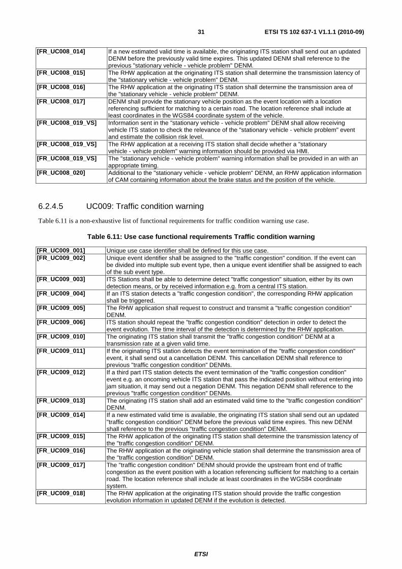
ETSI
ETSI TS 102 637-1 V1.1.1 (2010-09)31
[FR_UC008_014] If a new estimated valid time is available, the originating ITS station shall send out an updated DENM before the previously valid time expires. This updated DENM shall reference to the previous "stationary vehicle - vehicle problem" DENM.
[FR_UC008_015] The RHW application at the originating ITS station shall determine the transmission latency of the "stationary vehicle - vehicle problem" DENM.
[FR_UC008_016] The RHW application at the originating ITS station shall determine the transmission area of the "stationary vehicle - vehicle problem" DENM.
[FR_UC008_017] DENM shall provide the stationary vehicle position as the event location with a location referencing sufficient for matching to a certain road. The location reference shall include at least coordinates in the WGS84 coordinate system of the vehicle.
[FR_UC008_019_VS] Information sent in the "stationary vehicle - vehicle problem" DENM shall allow receiving vehicle ITS station to check the relevance of the "stationary vehicle - vehicle problem" event and estimate the collision risk level.
[FR_UC008_019_VS] The RHW application at a receiving ITS station shall decide whether a "stationary vehicle - vehicle problem" warning information should be provided via HMI.
[FR_UC008_019_VS] The "stationary vehicle - vehicle problem" warning information shall be provided in an with an appropriate timing.
[FR_UC008_020] Additional to the "stationary vehicle - vehicle problem" DENM, an RHW application information of CAM containing information about the brake status and the position of the vehicle.
6.2.4.5 UC009: Traffic condition warning
Table 6.11 is a non-exhaustive list of functional requirements for traffic condition warning use case.
Table 6.11: Use case functional requirements Traffic condition warning
[FR_UC009_001] Unique use case identifier shall be defined for this use case. [FR_UC009_002] Unique event identifier shall be assigned to the "traffic congestion" condition. If the event can
be divided into multiple sub event type, then a unique event identifier shall be assigned to each of the sub event type.
[FR_UC009_003] ITS Stations shall be able to determine detect "traffic congestion" situation, either by its own detection means, or by received information e.g. from a central ITS station.
[FR_UC009_004] If an ITS station detects a "traffic congestion condition", the corresponding RHW application shall be triggered.
[FR_UC009_005] The RHW application shall request to construct and transmit a "traffic congestion condition" DENM.
[FR_UC009_006] ITS station should repeat the "traffic congestion condition" detection in order to detect the event evolution. The time interval of the detection is determined by the RHW application.
[FR_UC009_010] The originating ITS station shall transmit the "traffic congestion condition" DENM at a transmission rate at a given valid time.
[FR_UC009_011] If the originating ITS station detects the event termination of the "traffic congestion condition" event, it shall send out a cancellation DENM. This cancellation DENM shall reference to previous "traffic congestion condition" DENMs.
[FR_UC009_012] If a third part ITS station detects the event termination of the "traffic congestion condition" event e.g. an oncoming vehicle ITS station that pass the indicated position without entering into jam situation, it may send out a negation DENM. This negation DENM shall reference to the previous "traffic congestion condition" DENMs.
[FR_UC009_013] The originating ITS station shall add an estimated valid time to the "traffic congestion condition" DENM.
[FR_UC009_014] If a new estimated valid time is available, the originating ITS station shall send out an updated "traffic congestion condition" DENM before the previous valid time expires. This new DENM shall reference to the previous "traffic congestion condition" DENM.
[FR_UC009_015] The RHW application of the originating ITS station shall determine the transmission latency of the "traffic congestion condition" DENM.
[FR_UC009_016] The RHW application at the originating vehicle station shall determine the transmission area of the "traffic congestion condition" DENM.
[FR_UC009_017] The "traffic congestion condition" DENM should provide the upstream front end of traffic congestion as the event position with a location referencing sufficient for matching to a certain road. The location reference shall include at least coordinates in the WGS84 coordinate system.
[FR_UC009_018] The RHW application at the originating ITS station should provide the traffic congestion evolution information in updated DENM if the evolution is detected.
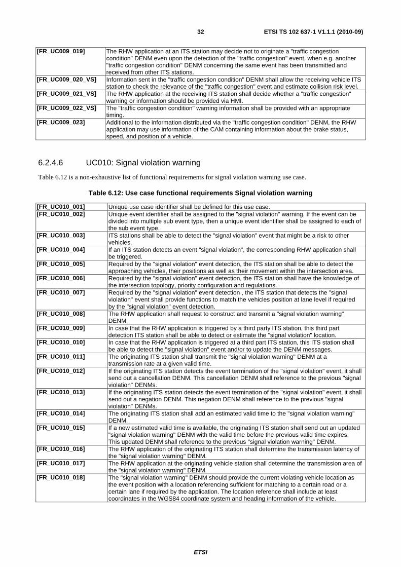
ETSI
ETSI TS 102 637-1 V1.1.1 (2010-09)32
[FR_UC009_019] The RHW application at an ITS station may decide not to originate a "traffic congestion condition" DENM even upon the detection of the "traffic congestion" event, when e.g. another "traffic congestion condition" DENM concerning the same event has been transmitted and received from other ITS stations.
[FR_UC009_020_VS] Information sent in the "traffic congestion condition" DENM shall allow the receiving vehicle ITS station to check the relevance of the "traffic congestion" event and estimate collision risk level.
[FR_UC009_021_VS] The RHW application at the receiving ITS station shall decide whether a "traffic congestion" warning or information should be provided via HMI.
[FR_UC009_022_VS] The "traffic congestion condition" warning information shall be provided with an appropriate timing.
[FR_UC009_023] Additional to the information distributed via the "traffic congestion condition" DENM, the RHW application may use information of the CAM containing information about the brake status, speed, and position of a vehicle.
6.2.4.6 UC010: Signal violation warning
Table 6.12 is a non-exhaustive list of functional requirements for signal violation warning use case.
Table 6.12: Use case functional requirements Signal violation warning
[FR_UC010_001] Unique use case identifier shall be defined for this use case. [FR_UC010_002] Unique event identifier shall be assigned to the "signal violation" warning. If the event can be
divided into multiple sub event type, then a unique event identifier shall be assigned to each of the sub event type.
[FR_UC010_003] ITS stations shall be able to detect the "signal violation" event that might be a risk to other vehicles.
[FR_UC010_004] If an ITS station detects an event "signal violation", the corresponding RHW application shall be triggered.
[FR_UC010_005] Required by the "signal violation" event detection, the ITS station shall be able to detect the approaching vehicles, their positions as well as their movement within the intersection area.
[FR_UC010_006] Required by the "signal violation" event detection, the ITS station shall have the knowledge of the intersection topology, priority configuration and regulations.
[FR_UC010_007] Required by the "signal violation" event detection , the ITS station that detects the "signal violation" event shall provide functions to match the vehicles position at lane level if required by the "signal violation" event detection.
[FR_UC010_008] The RHW application shall request to construct and transmit a "signal violation warning" DENM.
[FR_UC010_009] In case that the RHW application is triggered by a third party ITS station, this third part detection ITS station shall be able to detect or estimate the "signal violation" location.
[FR_UC010_010] In case that the RHW application is triggered at a third part ITS station, this ITS station shall be able to detect the "signal violation" event and/or to update the DENM messages.
[FR_UC010_011] The originating ITS station shall transmit the "signal violation warning" DENM at a transmission rate at a given valid time.
[FR_UC010_012] If the originating ITS station detects the event termination of the "signal violation" event, it shall send out a cancellation DENM. This cancellation DENM shall reference to the previous "signal violation" DENMs.
[FR_UC010_013] If the originating ITS station detects the event termination of the "signal violation" event, it shall send out a negation DENM. This negation DENM shall reference to the previous "signal violation" DENMs.
[FR_UC010_014] The originating ITS station shall add an estimated valid time to the "signal violation warning" DENM.
[FR_UC010_015] If a new estimated valid time is available, the originating ITS station shall send out an updated "signal violation warning" DENM with the valid time before the previous valid time expires. This updated DENM shall reference to the previous "signal violation warning" DENM.
[FR_UC010_016] The RHW application of the originating ITS station shall determine the transmission latency of the "signal violation warning" DENM.
[FR_UC010_017] The RHW application at the originating vehicle station shall determine the transmission area of the "signal violation warning" DENM.
[FR_UC010_018] The "signal violation warning" DENM should provide the current violating vehicle location as the event position with a location referencing sufficient for matching to a certain road or a certain lane if required by the application. The location reference shall include at least coordinates in the WGS84 coordinate system and heading information of the vehicle.
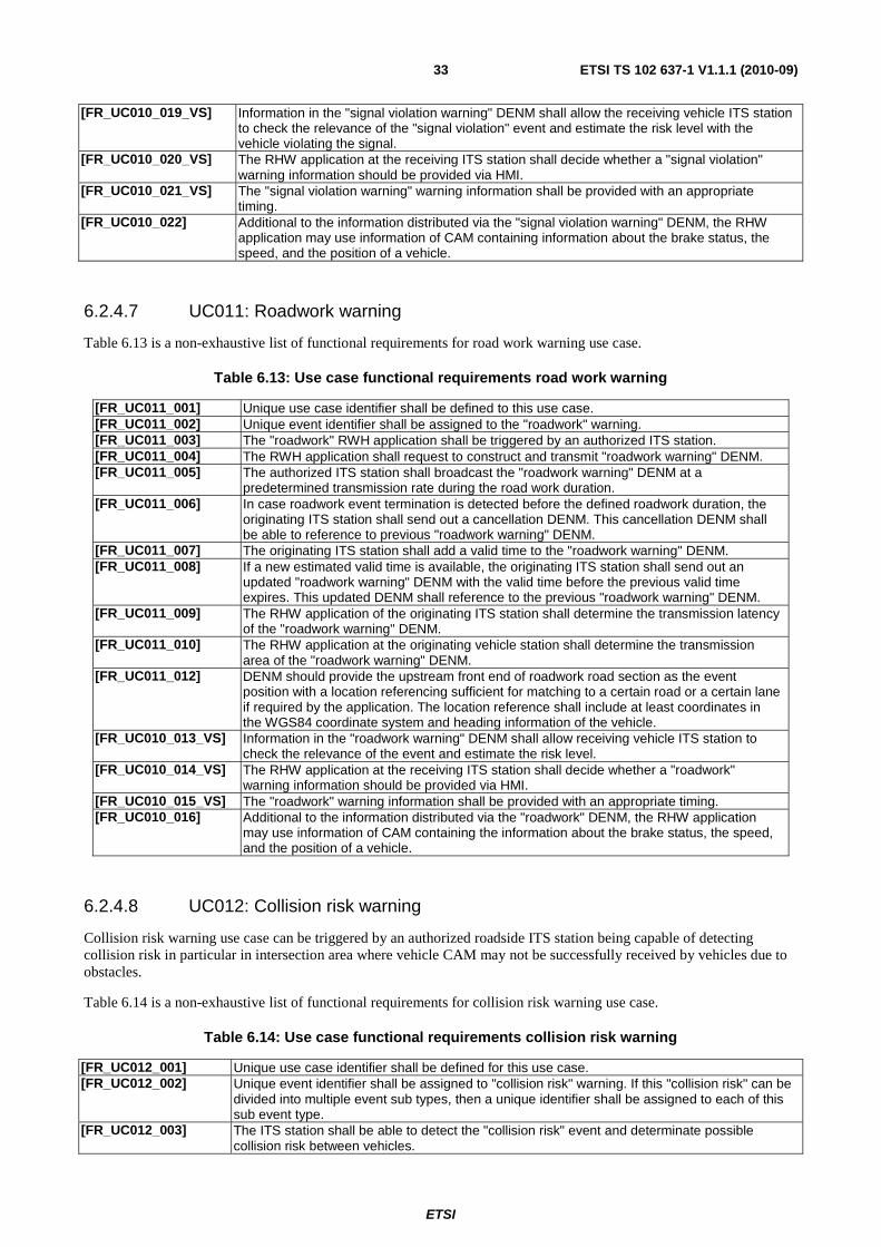
ETSI
ETSI TS 102 637-1 V1.1.1 (2010-09)33
[FR_UC010_019_VS] Information in the "signal violation warning" DENM shall allow the receiving vehicle ITS station to check the relevance of the "signal violation" event and estimate the risk level with the vehicle violating the signal.
[FR_UC010_020_VS] The RHW application at the receiving ITS station shall decide whether a "signal violation" warning information should be provided via HMI.
[FR_UC010_021_VS] The "signal violation warning" warning information shall be provided with an appropriate timing.
[FR_UC010_022] Additional to the information distributed via the "signal violation warning" DENM, the RHW application may use information of CAM containing information about the brake status, the speed, and the position of a vehicle.
6.2.4.7 UC011: Roadwork warning
Table 6.13 is a non-exhaustive list of functional requirements for road work warning use case.
Table 6.13: Use case functional requirements road work warning
[FR_UC011_001] Unique use case identifier shall be defined to this use case. [FR_UC011_002] Unique event identifier shall be assigned to the "roadwork" warning. [FR_UC011_003] The "roadwork" RWH application shall be triggered by an authorized ITS station. [FR_UC011_004] The RWH application shall request to construct and transmit "roadwork warning" DENM. [FR_UC011_005] The authorized ITS station shall broadcast the "roadwork warning" DENM at a
predetermined transmission rate during the road work duration. [FR_UC011_006] In case roadwork event termination is detected before the defined roadwork duration, the
originating ITS station shall send out a cancellation DENM. This cancellation DENM shall be able to reference to previous "roadwork warning" DENM.
[FR_UC011_007] The originating ITS station shall add a valid time to the "roadwork warning" DENM. [FR_UC011_008] If a new estimated valid time is available, the originating ITS station shall send out an
updated "roadwork warning" DENM with the valid time before the previous valid time expires. This updated DENM shall reference to the previous "roadwork warning" DENM.
[FR_UC011_009] The RHW application of the originating ITS station shall determine the transmission latency of the "roadwork warning" DENM.
[FR_UC011_010] The RHW application at the originating vehicle station shall determine the transmission area of the "roadwork warning" DENM.
[FR_UC011_012] DENM should provide the upstream front end of roadwork road section as the event position with a location referencing sufficient for matching to a certain road or a certain lane if required by the application. The location reference shall include at least coordinates in the WGS84 coordinate system and heading information of the vehicle.
[FR_UC010_013_VS] Information in the "roadwork warning" DENM shall allow receiving vehicle ITS station to check the relevance of the event and estimate the risk level.
[FR_UC010_014_VS] The RHW application at the receiving ITS station shall decide whether a "roadwork" warning information should be provided via HMI.
[FR_UC010_015_VS] The "roadwork" warning information shall be provided with an appropriate timing. [FR_UC010_016] Additional to the information distributed via the "roadwork" DENM, the RHW application
may use information of CAM containing the information about the brake status, the speed, and the position of a vehicle.
6.2.4.8 UC012: Collision risk warning
Collision risk warning use case can be triggered by an authorized roadside ITS station being capable of detecting collision risk in particular in intersection area where vehicle CAM may not be successfully received by vehicles due to obstacles.
Table 6.14 is a non-exhaustive list of functional requirements for collision risk warning use case.
Table 6.14: Use case functional requirements collision risk warning
[FR_UC012_001] Unique use case identifier shall be defined for this use case. [FR_UC012_002] Unique event identifier shall be assigned to "collision risk" warning. If this "collision risk" can be
divided into multiple event sub types, then a unique identifier shall be assigned to each of this sub event type.
[FR_UC012_003] The ITS station shall be able to detect the "collision risk" event and determinate possible collision risk between vehicles.

ETSI
ETSI TS 102 637-1 V1.1.1 (2010-09)34
[FR_UC012_004] The roadside ITS station or vehicle ITS station shall have the capabilities to detect and evaluate the collision risk between vehicles.
[FR_UC012_005] ITS station shall be able to detect the vehicles, their positions as well as their movement within the intersection area.
[FR_UC012_006] Required by the collision risk detection, the ITS station should be able to estimate the future itinerary of surrounding vehicles to cross the intersection.
[FR_UC012_007] Required by the collision risk detection, the vehicle ITS station should have the knowledge of its own future itinerary to cross the intersection area.
[FR_UC012_008] Required by the collision risk detection, the ITS station shall be able to determine or to estimate the possible crossing positions of the "collision risk" event.
[FR_UC012_009] If an ITS station detects a "collision risk" event, the corresponding RHW application shall be triggered.
[FR_UC012_010] The RHW application shall request to construct and transmit a "collision risk warning" DENM. [FR_UC012_011] The originating ITS station shall broadcast the "collision risk warning" DENM at a
predetermined transmission rate in a given valid time. [FR_UC012_012] If the originating ITS station detects the event termination of the "collision risk" event, it shall
send out a cancellation DENM. This cancellation DENM shall reference to the previous "collision risk" DENMs.
[FR_UC012_013] The originating ITS station shall add an estimated valid time to the "collision risk" DENM. [FR_UC012_014] If a new estimated valid time is available, the originating ITS station shall send out an updated
"collision risk" DENM with the valid time before the previous valid time expires. This updated DENM shall reference to the previous "collision risk" DENM.
[FR_UC012_015] The RHW application of the originating ITS station shall determine the transmission latency of the "collision risk" DENM.
[FR_UC012_016] The RHW application at the originating vehicle station shall determine the transmission area of the "collision risk" DENM.
[FR_UC012_017] The "collision risk" DENM should provide the determined or estimated collision position as the event position with a location referencing sufficient for matching to a certain road or a certain lane if required by the application. The location reference shall include at least coordinates in the WGS84 coordinate system and heading information of the vehicle.
[FR_UC012_018_VS] The RHW application of the receiving vehicle ITS station shall check the relevance of the risk level with regards to the event position.
[FR_UC012_019_VS] The RHW application at the receiving ITS station shall decide whether to deliver a "collision risk" warning information via HMI.
[FR_UC012_020_VS] The "collision risk" HMI warning shall be provided with an appropriate timing. [FR_UC012_022] Additional to the information distributed via the "collision risk" DENM, the RHW application may
use information of CAM containing information about brake status, speed, and location of a vehicle.
6.2.4.9 UC013: Decentralized floating car data - hazardous location
Table 6.15 is a non-exhaustive list of functional requirements for DFCD/hazardous location use case.
Table 6.15: Use case functional requirements hazardous location
[FR_UC013_001] Unique use case identifier shall be defined for this use case. [FR_UC013_002] Unique event identifier shall be assigned to the "hazardous location". If this "hazardous
location" can be divided into multiple event sub types, then a unique identifier shall be assigned to each of this sub event type.
[FR_UC013_003_VS] Vehicle ITS station shall have access to in vehicle sensor and in vehicle system to detect the "hazardous location".
[FR_UC013_004] ITS station shall be able to detect the "hazardous location" event that might be a risk to other vehicles.
[FR_UC013_005] ITS stations shall be able to determine or estimate the position of the "hazardous location" event and the evolution of the event.
[FR_UC013_006] If an ITS station detects a "hazardous location" event, the corresponding RHW application shall be triggered.
[FR_UC013_007] ITS station should repeat the "hazardous location" event detection in order to detect the event evolution. The time interval of the detection is determined by the RHW application.
[FR_UC013_008] The RHW application shall decide whether to request the construction and the transmission of a "hazardous location" DENM.
[FR_UC013_009] The ITS station shall be an authorized ITS station to originate the "hazardous location" DENM. [FR_UC013_010] The originating ITS station shall broadcast the "hazardous location" DENM at a predetermined
transmission rate in a given valid time.
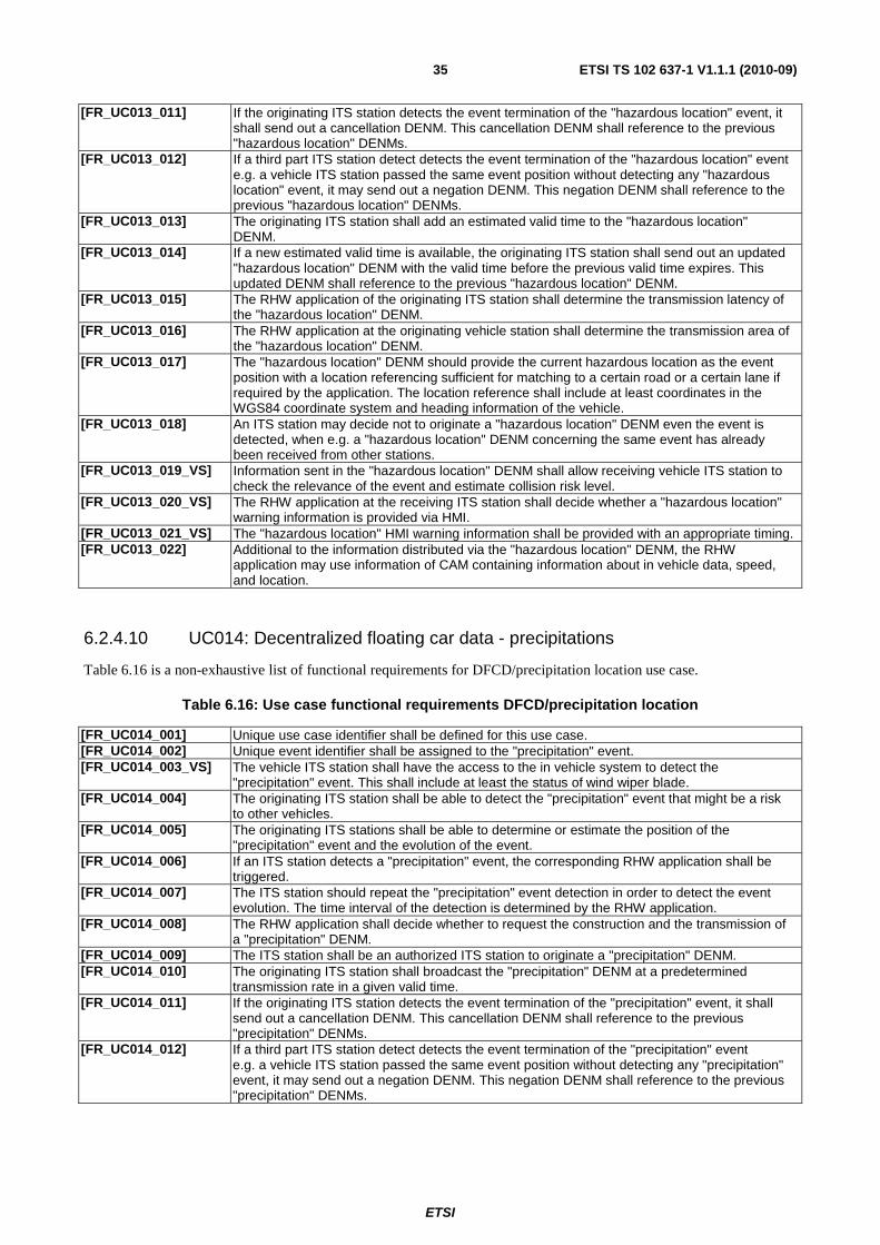
ETSI
ETSI TS 102 637-1 V1.1.1 (2010-09)35
[FR_UC013_011] If the originating ITS station detects the event termination of the "hazardous location" event, it shall send out a cancellation DENM. This cancellation DENM shall reference to the previous "hazardous location" DENMs.
[FR_UC013_012] If a third part ITS station detect detects the event termination of the "hazardous location" event e.g. a vehicle ITS station passed the same event position without detecting any "hazardous location" event, it may send out a negation DENM. This negation DENM shall reference to the previous "hazardous location" DENMs.
[FR_UC013_013] The originating ITS station shall add an estimated valid time to the "hazardous location" DENM.
[FR_UC013_014] If a new estimated valid time is available, the originating ITS station shall send out an updated "hazardous location" DENM with the valid time before the previous valid time expires. This updated DENM shall reference to the previous "hazardous location" DENM.
[FR_UC013_015] The RHW application of the originating ITS station shall determine the transmission latency of the "hazardous location" DENM.
[FR_UC013_016] The RHW application at the originating vehicle station shall determine the transmission area of the "hazardous location" DENM.
[FR_UC013_017] The "hazardous location" DENM should provide the current hazardous location as the event position with a location referencing sufficient for matching to a certain road or a certain lane if required by the application. The location reference shall include at least coordinates in the WGS84 coordinate system and heading information of the vehicle.
[FR_UC013_018] An ITS station may decide not to originate a "hazardous location" DENM even the event is detected, when e.g. a "hazardous location" DENM concerning the same event has already been received from other stations.
[FR_UC013_019_VS] Information sent in the "hazardous location" DENM shall allow receiving vehicle ITS station to check the relevance of the event and estimate collision risk level.
[FR_UC013_020_VS] The RHW application at the receiving ITS station shall decide whether a "hazardous location" warning information is provided via HMI.
[FR_UC013_021_VS] The "hazardous location" HMI warning information shall be provided with an appropriate timing. [FR_UC013_022] Additional to the information distributed via the "hazardous location" DENM, the RHW
application may use information of CAM containing information about in vehicle data, speed, and location.
6.2.4.10 UC014: Decentralized floating car data - precipitations
Table 6.16 is a non-exhaustive list of functional requirements for DFCD/precipitation location use case.
Table 6.16: Use case functional requirements DFCD/precipitation location
[FR_UC014_001] Unique use case identifier shall be defined for this use case. [FR_UC014_002] Unique event identifier shall be assigned to the "precipitation" event. [FR_UC014_003_VS] The vehicle ITS station shall have the access to the in vehicle system to detect the
"precipitation" event. This shall include at least the status of wind wiper blade. [FR_UC014_004] The originating ITS station shall be able to detect the "precipitation" event that might be a risk
to other vehicles. [FR_UC014_005] The originating ITS stations shall be able to determine or estimate the position of the
"precipitation" event and the evolution of the event. [FR_UC014_006] If an ITS station detects a "precipitation" event, the corresponding RHW application shall be
triggered. [FR_UC014_007] The ITS station should repeat the "precipitation" event detection in order to detect the event
evolution. The time interval of the detection is determined by the RHW application. [FR_UC014_008] The RHW application shall decide whether to request the construction and the transmission of
a "precipitation" DENM. [FR_UC014_009] The ITS station shall be an authorized ITS station to originate a "precipitation" DENM. [FR_UC014_010] The originating ITS station shall broadcast the "precipitation" DENM at a predetermined
transmission rate in a given valid time. [FR_UC014_011] If the originating ITS station detects the event termination of the "precipitation" event, it shall
send out a cancellation DENM. This cancellation DENM shall reference to the previous "precipitation" DENMs.
[FR_UC014_012] If a third part ITS station detect detects the event termination of the "precipitation" event e.g. a vehicle ITS station passed the same event position without detecting any "precipitation" event, it may send out a negation DENM. This negation DENM shall reference to the previous "precipitation" DENMs.
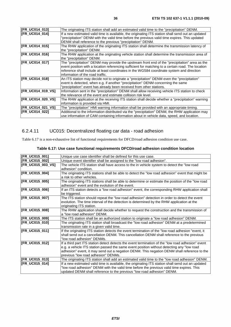
ETSI
ETSI TS 102 637-1 V1.1.1 (2010-09)36
[FR_UC014_013] The originating ITS station shall add an estimated valid time to the "precipitation" DENM. [FR_UC014_014] If a new estimated valid time is available, the originating ITS station shall send out an updated
"precipitation" DENM with the valid time before the previous valid time expires. This updated DENM shall reference to the previous "precipitation" DENM.
[FR_UC014_015] The RHW application of the originating ITS station shall determine the transmission latency of the "precipitation" DENM.
[FR_UC014_016] The RHW application at the originating vehicle station shall determine the transmission area of the "precipitation" DENM.
[FR_UC014_017] The "precipitation" DENM may provide the upstream front end of the "precipitation" area as the event position with a location referencing sufficient for matching to a certain road. The location reference shall include at least coordinates in the WGS84 coordinate system and direction information of the road traffic.
[FR_UC014_018] An ITS station may decide not to originate a "precipitation" DENM even the "precipitation" event is detected, when e.g. if another "precipitation" DENM concerning the same "precipitation" event has already been received from other stations.
[FR_UC014_019_VS] Information sent in the "precipitation" DENM shall allow receiving vehicle ITS station to check the relevance of the event and estimate collision risk level.
[FR_UC014_020_VS] The RHW application at the receiving ITS station shall decide whether a "precipitation" warning information is provided via HMI.
[FR_UC014_021_VS] The "precipitation" HMI warning information shall be provided with an appropriate timing. [FR_UC014_022] Additional to the information distributed via the "precipitation" DENM, the RHW application may
use information of CAM containing information about in vehicle data, speed, and location.
6.2.4.11 UC015: Decentralized floating car data - road adhesion
Table 6.17 is a non-exhaustive list of functional requirements for DFCD/road adhesion condition use case.
Table 6.17: Use case functional requirements DFCD/road adhesion condition location
[FR_UC015_001] Unique use case identifier shall be defined for this use case. [FR_UC015_002] Unique event identifier shall be assigned to the "low road adhesion". [FR_UC015_003_VS] The vehicle ITS station shall have access to the in vehicle system to detect the "low road
adhesion" condition. [FR_UC015_004] The originating ITS stations shall be able to detect the "low road adhesion" event that might be
a risk to other vehicles. [FR_UC015_005] The originating ITS stations shall be able to determine or estimate the position of the "low road
adhesion" event and the evolution of the event. [FR_UC015_006] If an ITS station detects a "low road adhesion" event, the corresponding RHW application shall
be triggered. [FR_UC015_007] The ITS station should repeat the "low road adhesion" detection in order to detect the event
evolution. The time interval of the detection is determined by the RHW application at the originating ITS station.
[FR_UC015_008] The RHW application shall decide whether to request the construction and the transmission of a "low road adhesion" DENM.
[FR_UC015_009] The ITS station shall be an authorized station to originate a "low road adhesion" DENM. [FR_UC015_010] The originating ITS station shall broadcast the "low road adhesion" DENM at a predetermined
transmission rate in a given valid time. [FR_UC015_011] If the originating ITS station detects the event termination of the "low road adhesion "event, it
shall send out a cancellation DENM. This cancellation DENM shall reference to the previous "low road adhesion" DENMs.
[FR_UC015_012] If a third part ITS station detect detects the event termination of the "low road adhesion" event e.g. a vehicle ITS station passed the same event position without detecting any "low road adhesion" event, it may send out a negation DENM. This negation DENM shall reference to the previous "low road adhesion" DENMs.
[FR_UC015_013] The originating ITS station shall add an estimated valid time to the "low road adhesion" DENM. [FR_UC015_014] If a new estimated valid time is available, the originating ITS station shall send out an updated
"low road adhesion" DENM with the valid time before the previous valid time expires. This updated DENM shall reference to the previous "low road adhesion" DENM.
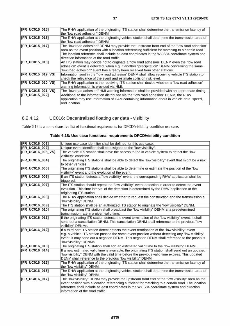
ETSI
ETSI TS 102 637-1 V1.1.1 (2010-09)37
[FR_UC015_015] The RHW application of the originating ITS station shall determine the transmission latency of the "low road adhesion" DENM.
[FR_UC015_016] The RHW application at the originating vehicle station shall determine the transmission area of the "low road adhesion" DENM.
[FR_UC015_017] The "low road adhesion" DENM may provide the upstream front end of the "low road adhesion" area as the event position with a location referencing sufficient for matching to a certain road. The location reference shall include at least coordinates in the WGS84 coordinate system and direction information of the road traffic.
[FR_UC015_018] An ITS station may decide not to originate a "low road adhesion" DENM even the "low road adhesion" event is detected, when e.g. if another "precipitation" DENM concerning the same "low road adhesion" event has already been received from other stations.
[FR_UC015_019_VS] Information sent in the "low road adhesion" DENM shall allow receiving vehicle ITS station to check the relevance of the event and estimate collision risk level.
[FR_UC015_020_VS] The RHW application at the receiving ITS station shall decide whether a "low road adhesion" warning information is provided via HMI.
[FR_UC015_021_VS] The "low road adhesion" HMI warning information shall be provided with an appropriate timing. [FR_UC015_022] Additional to the information distributed via the "low road adhesion" DENM, the RHW
application may use information of CAM containing information about in vehicle data, speed, and location.
6.2.4.12 UC016: Decentralized floating car data - visibility
Table 6.18 is a non-exhaustive list of functional requirements for DFCD/visibility condition use case.
Table 6.18: Use case functional requirements DFCD/visibility condition
[FR_UC016_001] Unique use case identifier shall be defined for this use case. [FR_UC016_002] Unique event identifier shall be assigned to the "low visibility". [FR_UC016_003_VS] The vehicle ITS station shall have the access to the in vehicle system to detect the "low
visibility" condition. [FR_UC016_004] The originating ITS stations shall be able to detect the "low visibility" event that might be a risk
to other vehicles. [FR_UC016_005] The originating ITS stations shall be able to determine or estimate the position of the "low
visibility" event and the evolution of the event. [FR_UC016_006] If an ITS station detects a "low visibility" event, the corresponding RHW application shall be
triggered. [FR_UC016_007] The ITS station should repeat the "low visibility" event detection in order to detect the event
evolution. This time interval of the detection is determined by the RHW application at the originating ITS station.
[FR_UC016_008] The RHW application shall decide whether to request the construction and the transmission a "low visibility" DENM.
[FR_UC016_009] The ITS station shall be an authorized ITS station to originate the "low visibility" DENM. [FR_UC016_010] The originating ITS station shall broadcast the "low visibility" DENM at a predetermined
transmission rate in a given valid time. [FR_UC016_011] If the originating ITS station detects the event termination of the "low visibility" event, it shall
send out a cancellation DENM. This cancellation DENM shall reference to the previous "low visibility" DENMs.
[FR_UC016_012] If a third part ITS station detect detects the event termination of the "low visibility" event e.g. a vehicle ITS station passed the same event position without detecting any "low visibility" event, it may send out a negation DENM. This negation DENM shall reference to the previous "low visibility" DENMs.
[FR_UC016_013] The originating ITS station shall add an estimated valid time to the "low visibility" DENM. [FR_UC016_014] If a new estimated valid time is available, the originating ITS station shall send out an updated
"low visibility" DENM with the valid time before the previous valid time expires. This updated DENM shall reference to the previous "low visibility" DENM.
[FR_UC016_015] The RHW application of the originating ITS station shall determine the transmission latency of the "low visibility" DENM.
[FR_UC016_016] The RHW application at the originating vehicle station shall determine the transmission area of the "low visibility" DENM.
[FR_UC016_017] The "low visibility" DENM may provide the upstream front end of the "low visibility" area as the event position with a location referencing sufficient for matching to a certain road. The location reference shall include at least coordinates in the WGS84 coordinate system and direction information of the road traffic.
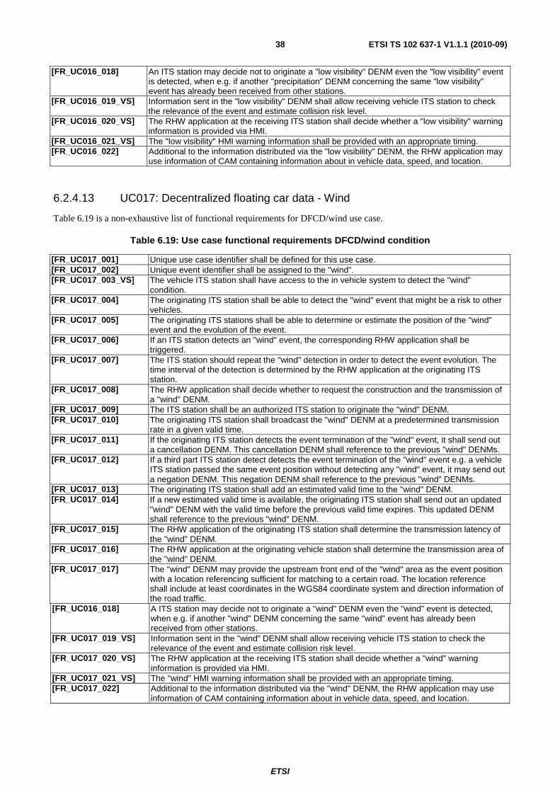
ETSI
ETSI TS 102 637-1 V1.1.1 (2010-09)38
[FR_UC016_018] An ITS station may decide not to originate a "low visibility" DENM even the "low visibility" event is detected, when e.g. if another "precipitation" DENM concerning the same "low visibility" event has already been received from other stations.
[FR_UC016_019_VS] Information sent in the "low visibility" DENM shall allow receiving vehicle ITS station to check the relevance of the event and estimate collision risk level.
[FR_UC016_020_VS] The RHW application at the receiving ITS station shall decide whether a "low visibility" warning information is provided via HMI.
[FR_UC016_021_VS] The "low visibility" HMI warning information shall be provided with an appropriate timing. [FR_UC016_022] Additional to the information distributed via the "low visibility" DENM, the RHW application may
use information of CAM containing information about in vehicle data, speed, and location.
6.2.4.13 UC017: Decentralized floating car data - Wind
Table 6.19 is a non-exhaustive list of functional requirements for DFCD/wind use case.
Table 6.19: Use case functional requirements DFCD/wind condition
[FR_UC017_001] Unique use case identifier shall be defined for this use case. [FR_UC017_002] Unique event identifier shall be assigned to the "wind". [FR_UC017_003_VS] The vehicle ITS station shall have access to the in vehicle system to detect the "wind"
condition. [FR_UC017_004] The originating ITS station shall be able to detect the "wind" event that might be a risk to other
vehicles. [FR_UC017_005] The originating ITS stations shall be able to determine or estimate the position of the "wind"
event and the evolution of the event. [FR_UC017_006] If an ITS station detects an "wind" event, the corresponding RHW application shall be
triggered. [FR_UC017_007] The ITS station should repeat the "wind" detection in order to detect the event evolution. The
time interval of the detection is determined by the RHW application at the originating ITS station.
[FR_UC017_008] The RHW application shall decide whether to request the construction and the transmission of a "wind" DENM.
[FR_UC017_009] The ITS station shall be an authorized ITS station to originate the "wind" DENM. [FR_UC017_010] The originating ITS station shall broadcast the "wind" DENM at a predetermined transmission
rate in a given valid time. [FR_UC017_011] If the originating ITS station detects the event termination of the "wind" event, it shall send out
a cancellation DENM. This cancellation DENM shall reference to the previous "wind" DENMs. [FR_UC017_012] If a third part ITS station detect detects the event termination of the "wind" event e.g. a vehicle
ITS station passed the same event position without detecting any "wind" event, it may send out a negation DENM. This negation DENM shall reference to the previous "wind" DENMs.
[FR_UC017_013] The originating ITS station shall add an estimated valid time to the "wind" DENM. [FR_UC017_014] If a new estimated valid time is available, the originating ITS station shall send out an updated
"wind" DENM with the valid time before the previous valid time expires. This updated DENM shall reference to the previous "wind" DENM.
[FR_UC017_015] The RHW application of the originating ITS station shall determine the transmission latency of the "wind" DENM.
[FR_UC017_016] The RHW application at the originating vehicle station shall determine the transmission area of the "wind" DENM.
[FR_UC017_017] The "wind" DENM may provide the upstream front end of the "wind" area as the event position with a location referencing sufficient for matching to a certain road. The location reference shall include at least coordinates in the WGS84 coordinate system and direction information of the road traffic.
[FR_UC016_018] A ITS station may decide not to originate a "wind" DENM even the "wind" event is detected, when e.g. if another "wind" DENM concerning the same "wind" event has already been received from other stations.
[FR_UC017_019_VS] Information sent in the "wind" DENM shall allow receiving vehicle ITS station to check the relevance of the event and estimate collision risk level.
[FR_UC017_020_VS] The RHW application at the receiving ITS station shall decide whether a "wind" warning information is provided via HMI.
[FR_UC017_021_VS] The "wind" HMI warning information shall be provided with an appropriate timing. [FR_UC017_022] Additional to the information distributed via the "wind" DENM, the RHW application may use
information of CAM containing information about in vehicle data, speed, and location.
ETSI
ETSI TS 102 637-1 V1.1.1 (2010-09)39
6.3 Speed management
6.3.1 Application overview
Co-operative Speed Management (CSM) application consists of providing the speed information to road users in order to improve the road traffic efficiency. This application provides either regulatory speed limit information (static or dynamic information provided by an authorized central ITS station) or recommended contextual speed to drivers at a specific road locations such as highway, urban road or intersections equipped with traffic lights. The main characteristic of this application is that a roadside ITS station transmits the speed information or the information necessary for an optimal speed calculation to the vehicle ITS station. Preferably, the roadside ITS station has point-to-point communication with the central ITS station.
NOTE: For the BSA use cases belonging to this application, speed information is required to be provided to drivers via HMI, no direct actions to vehicle brake or electronic system is required.
Two communication need to be established for this application:
• Communication between central ITS station and roadside ITS station.
• Communication between roads side ITS station and vehicle ITS station.
6.3.1.1 Communication between Central ITS station and roadside ITS station
This communication allows the central ITS station to provide dynamic update information for the speed management to the roadside ITS station via a wired or wireless communication. Each central ITS station has a competence area for which the speed management service is provided.
For this purpose, the central ITS station has the knowledge of the road site ITS stations located within its competence area, including e.g. the position, identifier, and networking address of each roadside ITS station as well as its relevant road section and traffic direction. Once a speed management information is required to be provided to a local area, the central ITS station should transmit the corresponding speed limit information to a roadside ITS stations located in this specified area.
The roadside ITS stations shall be authorized by the central ITS station to provide the speed management applications and services.
6.3.1.2 Communication between roadside ITS station and vehicle ITS station
Upon receiving a speed management information from the central station, roadside station should check the relevance of the information. After this processing, the CSM application at the roadside ITS station is able to provide the speed information to vehicles. Depending on the use case requirement, roadside station may provide:
• Regulatory speed limit information. The information is broadcasted to vehicle ITS stations.
• Advisory speed information. The information is broadcasted to vehicle ITS stations.
• Information necessary for optimal speed calculation. In this case, necessary functionalities for the calculation of optimal speed are in the vehicle ITS station. Roadside ITS station provides necessary information from roadside (i.e. traffic light phase and time) to assist this calculation. The information is broadcasted to all approaching vehicles.
For all above scenarios, the roadside ITS station should provide the area and location referencing information of this area where the provide information is valid. Furthermore, the roadside ITS station shall announce such speed management services.
Receiving vehicle ITS station shall check the relevance of the speed information. Proper warning or speed information may be provided to driver via HMI.
Two use cases are identified in BSA for this application:
• UC018: Regulatory/contextual speed limits notification;
• UC019: Traffic light optimal speed advisory.
ETSI
ETSI TS 102 637-1 V1.1.1 (2010-09)40
6.3.2 Application flow diagram
The CSM application flow diagram can be represented by the following figure 6.3. Only communication between the roadside ITS station and the vehicle ITS stations is presented.
NOTE: It is assumed that the service announcement has been realized before hand. Therefore, it is not included in the flow diagram.
1) The CSM application of the roadside ITS station process and manages the speed management information provided by the central ITS station.
2) CSM application sends to the facilities layer the information related to the speed management and parameters associated.
3) The facilities layer process the information and construct the "speed management" V2X message.
4) The facilities layer delivers a send request for the "speed management" V2X message and provide the "speed management" V2X message and the communication requirements to the network and transport layer.
5) Lower layer processing of the "speed management" V2X message to construct packets ready to be transmitted.
6) The packets are transmitted over the selected communication profile.
7) Lower layer processing of the packets and "speed management" V2X message is extracted.
8) The "speed management" V2X message is delivered to the facilities layer if the receiving ITS station is the destination ITS station.
9) The facilities layer processes the "speed management" V2X message.
10) If judged necessary by the facilities layer, it issues the "speed management" information to the application layer.
11) The application layer processes the information received from the facilities layer and decides or not to provide some information to the driver.
12) Application informs the driver of speed information via its HMI.
13) This step is present if the use case requires a periodical broadcasting of speed management information. Next scheduled time for transmission of the "speed management" V2X message.
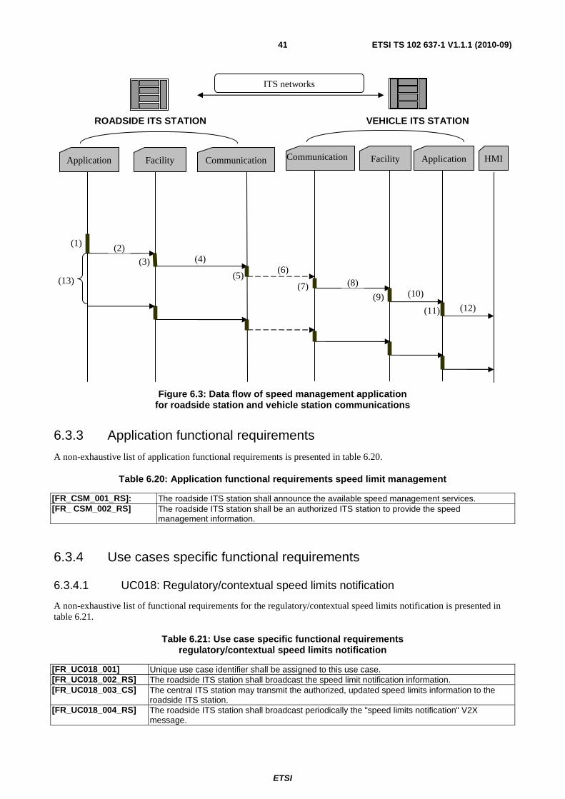
ETSI
ETSI TS 102 637-1 V1.1.1 (2010-09)41
Figure 6.3: Data flow of speed management application for roadside station and vehicle station communications
6.3.3 Application functional requirements
A non-exhaustive list of application functional requirements is presented in table 6.20.
Table 6.20: Application functional requirements speed limit management
[FR_CSM_001_RS]: The roadside ITS station shall announce the available speed management services. [FR_ CSM_002_RS] The roadside ITS station shall be an authorized ITS station to provide the speed
management information.
6.3.4 Use cases specific functional requirements
6.3.4.1 UC018: Regulatory/contextual speed limits notification
A non-exhaustive list of functional requirements for the regulatory/contextual speed limits notification is presented in table 6.21.
Table 6.21: Use case specific functional requirements regulatory/contextual speed limits notification
[FR_UC018_001] Unique use case identifier shall be assigned to this use case. [FR_UC018_002_RS] The roadside ITS station shall broadcast the speed limit notification information. [FR_UC018_003_CS] The central ITS station may transmit the authorized, updated speed limits information to the
roadside ITS station. [FR_UC018_004_RS] The roadside ITS station shall broadcast periodically the "speed limits notification" V2X
message.
Application
ROADSIDE ITS STATION
Facility Communication Communication Facility Application
VEHICLE ITS STATION
HMI
ITS networks
(1) (2)
(3) (4)
(5)(6)
(7) (8)
(9) (10)
(11) (12)
(13)
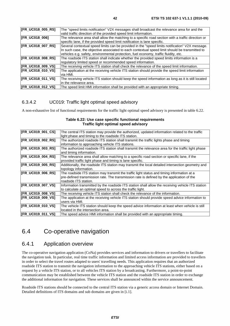
ETSI
ETSI TS 102 637-1 V1.1.1 (2010-09)42
[FR_UC018_005_RS] The "speed limits notification" V2X messages shall broadcast the relevance area for and the valid traffic direction of the provided speed limit information.
[FR_UC018_006] The relevance area shall allow the matching to a specific road section with a traffic direction or specific lane, if the provided speed limit notification is lane specific.
[FR_UC018_007_RS] Several contextual speed limits can be provided in the "speed limits notification" V2X message. In such case, the objective associated to each contextual speed limit should be transmitted to vehicles e.g. safety, environmental protection, fuel economy, traffic fluidity, etc.
[FR_UC018_008_RS] The roadside ITS station shall indicate whether the provided speed limits information is a regulatory limited speed or recommended speed information.
[FR_UC018_009_VS] The receiving vehicle ITS station shall check the relevance of the speed limit information. [FR_UC018_010_VS] The application at the receiving vehicle ITS station should provide the speed limit information
via HMI. [FR_UC018_011_VS] The receiving vehicle ITS station should keep the speed information as long as it is still located
in the relevance area. [FR_UC018_012_VS] The speed limit HMI information shall be provided with an appropriate timing.
6.3.4.2 UC019: Traffic light optimal speed advisory
A non-exhaustive list of functional requirements for the traffic light optimal speed advisory is presented in table 6.22.
Table 6.22: Use case specific functional requirements Traffic light optimal speed advisory
[FR_UC019_001_CS] The central ITS station may provide the authorized, updated information related to the traffic light phase and timing to the roadside ITS station.
[FR_UC019_002_RS] The authorized roadside ITS station shall transmit the traffic lights phase and timing information to approaching vehicle ITS stations.
[FR_UC019_003_RS] The authorized roadside ITS station shall transmit the relevance area for the traffic light phase and timing information.
[FR_UC019_004_RS] The relevance area shall allow matching to a specific road section or specific lane, if the provided traffic light phase and timing is lane specific.
[FR_UC019_005_RS] Additionally, the roadside ITS station may transmit the local detailed intersection geometry and topology information.
[FR_UC019_006_RS] The roadside ITS station may transmit the traffic light status and timing information at a pre-defined transmission rate. The transmission rate is defined by the application of the roadside ITS station.
[FR_UC019_007_VS] Information transmitted by the roadside ITS station shall allow the receiving vehicle ITS station to calculate an optimal speed to across the traffic light.
[FR_UC019_008_VS] The receiving vehicle ITS station shall check the relevance of the information. [FR_UC019_009_VS] The application at the receiving vehicle ITS station should provide speed advice information to
users via HMI. [FR_UC019_010_VS] The vehicle ITS station should keep the speed advice information at least when vehicle is still
located in the intersection area. [FR_UC019_011_VS] The speed advice HMI information shall be provided with an appropriate timing.
6.4 Co-operative navigation
6.4.1 Application overview
The co-operative navigation application (CoNa) provides services and information to drivers or travellers to facilitate the navigation task. In particular, real time traffic information and limited access information are provided to travellers in order to select the travel routes adapted to users' travelling needs. This application requires that an authorized roadside ITS station to transmit the navigation information to the approaching vehicle ITS stations, either based on a request by a vehicle ITS station, or to all vehicles ITS station by a broadcasting. Furthermore, a point-to-point communication may be established between the vehicle ITS station and the roadside ITS station in order to exchange the additional information for navigation. These services shall be announced within the service announcement.
Roadside ITS stations should be connected to the central ITS station via a generic access domain or Internet Domain. Detailed definitions of ITS domains and sub domains are given in [i.1].
ETSI
ETSI TS 102 637-1 V1.1.1 (2010-09)43
Two communications may be needed for this application:
• Communications between the central ITS station to the roadside ITS stations.
• Communications between the roadside ITS station to the vehicles ITS stations.
6.4.1.1 Communications between the central ITS station and the roadside ITS stations
The central ITS station can be an authorized traffic management centre providing the traffic information or a navigation service provider providing on demand navigation services to clients. The central ITS station is able to transmit the navigation service information to the roadside ITS stations via this communication.
NOTE: The co-operative navigation service provider can request real time traffic information to a backend systems such as a traffic management operator. Communication and information exchanges between the central ITS station and the backend systems is out of scope of the present document.
6.4.1.2 Communications between the roadside ITS station and the vehicle ITS stations
The roadside ITS station shall first performs a service announcement to the approaching vehicle ITS stations, announcing the availability of one or several co-operative navigation services. The real time traffic information and/or navigation assistance information are provided from the roadside ITS station to approaching vehicle ITS stations. If the use case is request based, the roadside ITS station transmits real time traffic information and/or the navigation service information to the request vehicle via point-to-point communication or a geo-unicast communication.
At receiving vehicle ITS station, the vehicle ITS station processes the received information and provide the navigation information via a HMI.
Four use cases are assigned to this application within BSA:
• Traffic information and recommended itinerary.
• Enhanced route guidance and navigation.
• Limited access and detour notification.
• In-vehicle signage.
6.4.2 Application flow diagram
The CoNa application flow diagram can be represented by the following figure 6.4. Only communication between the roadside ITS station and the vehicle ITS stations are presented in the figure. It is assumed that the service announcement has been realized beforehand.
1) This step is only present for the request based scenario. Vehicle ITS station initiate navigation service request to the roadside ITS station announcing the service.
2) This step is only present for the request based scenario. The facilities layer constructs a request message.
3) This step is only present for the request based scenario. The facilities layer deliverers the request message to lower layers with communication requirements.
4) This step is only present for the request based scenario. Lower layer process the request message and constructs packets ready for transmission.
5) This step is only present for the request based scenario. Packets are transmitted over the selected communication profile.
6) This step is only present for the request based scenario. Lower layer process the received packets.
7) This step is only present for the request based scenario. Request message payload is delivered to facilities layer.
ETSI
ETSI TS 102 637-1 V1.1.1 (2010-09)44
8) This step is only present for the request based scenario. The facilities layer process the received request message.
9) This step is only present for the request based scenario. The request information is provided to the application at roadside ITS station.
10) In a broadcast based scenario, the application at the roadside ITS station requests a broadcast of the navigation information. In a request based scenario, the application at the roadside ITS station process the request and requests the transmission of the navigation assistance information in reply to the request.
11) Roadside ITS station delivers the navigation assistance information and communication requirements to facilities layer.
12) The facilities layer process the navigation assistance information and constructs the navigation assistance messages.
13) The facilities layer delivers the navigation assistance message to lower layers with communication requirement information to the network and transport layer.
14) Lower layer process the navigation assistance messages and constructs packets for the transmission.
15) Packets are transmitted over the selected communication profile.
16) The lower layer process the received packets.
17) If the receiving ITS station is the relevance area or the request vehicle ITS station, the navigation assistance message is delivered to the facilities layer.
18) The facilities layer process the navigation assistance message.
19) The navigation assistance information is delivered to the application.
20) The application process the information.
21) The navigation assistance information is presented to user via HMI.
22) In a broadcast based scenario, the application delivers a send request of the navigation assistance information periodically.
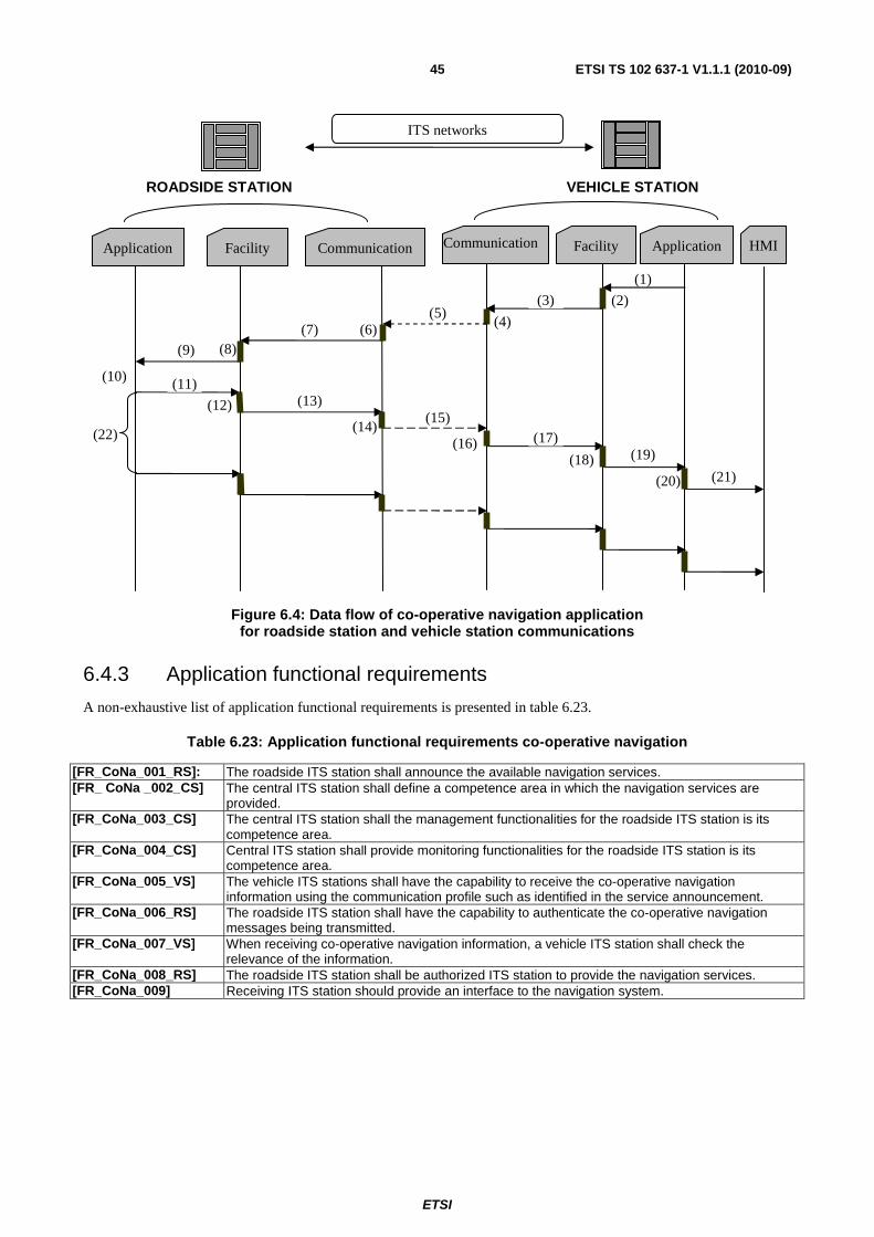
ETSI
ETSI TS 102 637-1 V1.1.1 (2010-09)45
Figure 6.4: Data flow of co-operative navigation application for roadside station and vehicle station communications
6.4.3 Application functional requirements
A non-exhaustive list of application functional requirements is presented in table 6.23.
Table 6.23: Application functional requirements co-operative navigation
[FR_CoNa_001_RS]: The roadside ITS station shall announce the available navigation services. [FR_ CoNa _002_CS] The central ITS station shall define a competence area in which the navigation services are
provided. [FR_CoNa_003_CS] The central ITS station shall the management functionalities for the roadside ITS station is its
competence area. [FR_CoNa_004_CS] Central ITS station shall provide monitoring functionalities for the roadside ITS station is its
competence area. [FR_CoNa_005_VS] The vehicle ITS stations shall have the capability to receive the co-operative navigation
information using the communication profile such as identified in the service announcement. [FR_CoNa_006_RS] The roadside ITS station shall have the capability to authenticate the co-operative navigation
messages being transmitted. [FR_CoNa_007_VS] When receiving co-operative navigation information, a vehicle ITS station shall check the
relevance of the information. [FR_CoNa_008_RS] The roadside ITS station shall be authorized ITS station to provide the navigation services. [FR_CoNa_009] Receiving ITS station should provide an interface to the navigation system.
Application
ROADSIDE STATION
Facility Communication
(1)
Communication Facility Application
VEHICLE STATION
HMI
ITS networks
(2) (3)
(4) (5)
(6)(7) (8)(9)
(10) (11)
(12) (13)
(14)(15)
(16) (17)
(18) (19)
(20) (21)
(22)
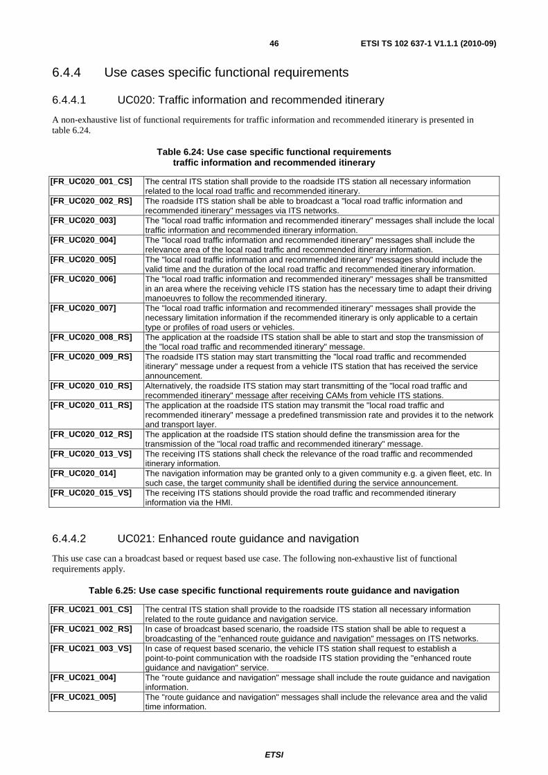
ETSI
ETSI TS 102 637-1 V1.1.1 (2010-09)46
6.4.4 Use cases specific functional requirements
6.4.4.1 UC020: Traffic information and recommended itinerary
A non-exhaustive list of functional requirements for traffic information and recommended itinerary is presented in table 6.24.
Table 6.24: Use case specific functional requirements traffic information and recommended itinerary
[FR_UC020_001_CS] The central ITS station shall provide to the roadside ITS station all necessary information related to the local road traffic and recommended itinerary.
[FR_UC020_002_RS] The roadside ITS station shall be able to broadcast a "local road traffic information and recommended itinerary" messages via ITS networks.
[FR_UC020_003] The "local road traffic information and recommended itinerary" messages shall include the local traffic information and recommended itinerary information.
[FR_UC020_004] The "local road traffic information and recommended itinerary" messages shall include the relevance area of the local road traffic and recommended itinerary information.
[FR_UC020_005] The "local road traffic information and recommended itinerary" messages should include the valid time and the duration of the local road traffic and recommended itinerary information.
[FR_UC020_006] The "local road traffic information and recommended itinerary" messages shall be transmitted in an area where the receiving vehicle ITS station has the necessary time to adapt their driving manoeuvres to follow the recommended itinerary.
[FR_UC020_007] The "local road traffic information and recommended itinerary" messages shall provide the necessary limitation information if the recommended itinerary is only applicable to a certain type or profiles of road users or vehicles.
[FR_UC020_008_RS] The application at the roadside ITS station shall be able to start and stop the transmission of the "local road traffic and recommended itinerary" message.
[FR_UC020_009_RS] The roadside ITS station may start transmitting the "local road traffic and recommended itinerary" message under a request from a vehicle ITS station that has received the service announcement.
[FR_UC020_010_RS] Alternatively, the roadside ITS station may start transmitting of the "local road traffic and recommended itinerary" message after receiving CAMs from vehicle ITS stations.
[FR_UC020_011_RS] The application at the roadside ITS station may transmit the "local road traffic and recommended itinerary" message a predefined transmission rate and provides it to the network and transport layer.
[FR_UC020_012_RS] The application at the roadside ITS station should define the transmission area for the transmission of the "local road traffic and recommended itinerary" message.
[FR_UC020_013_VS] The receiving ITS stations shall check the relevance of the road traffic and recommended itinerary information.
[FR_UC020_014] The navigation information may be granted only to a given community e.g. a given fleet, etc. In such case, the target community shall be identified during the service announcement.
[FR_UC020_015_VS] The receiving ITS stations should provide the road traffic and recommended itinerary information via the HMI.
6.4.4.2 UC021: Enhanced route guidance and navigation
This use case can a broadcast based or request based use case. The following non-exhaustive list of functional requirements apply.
Table 6.25: Use case specific functional requirements route guidance and navigation
[FR_UC021_001_CS] The central ITS station shall provide to the roadside ITS station all necessary information related to the route guidance and navigation service.
[FR_UC021_002_RS] In case of broadcast based scenario, the roadside ITS station shall be able to request a broadcasting of the "enhanced route guidance and navigation" messages on ITS networks.
[FR_UC021_003_VS] In case of request based scenario, the vehicle ITS station shall request to establish a point-to-point communication with the roadside ITS station providing the "enhanced route guidance and navigation" service.
[FR_UC021_004] The "route guidance and navigation" message shall include the route guidance and navigation information.
[FR_UC021_005] The "route guidance and navigation" messages shall include the relevance area and the valid time information.

ETSI
ETSI TS 102 637-1 V1.1.1 (2010-09)47
[FR_UC021_006] The "route guidance and navigation" messages shall be transmitted to a location where the receiving vehicle ITS station has the necessary time to adapt their driving manoeuvres to follow the guidance and navigation information.
[FR_UC021_007] The "route guidance and navigation" messages shall provide the necessary limitation information if the recommended itinerary is only applicable to a certain type or profiles of road users or vehicles.
[FR_UC021_008_RS] In case of broadcast based scenario. The roadside ITS station shall be able to start and stop the broadcasting of the "route guidance and navigation" messages.
[FR_UC021_009_RS] In case of a request based scenario, the roadside ITS station may start the transmission of the "route guidance and navigation" messages under a request from a vehicle ITS station that has received the service announcement.
[FR_UC021_011_RS] Alternatively, the roadside ITS station may start broadcasting of the "route guidance and navigation" messages after receiving CAMs from vehicle ITS stations.
[FR_UC021_012_RS] The roadside ITS station may transmit the "route guidance and navigation" messages with a predefined transmission rate.
[FR_UC021_013_RS] The application at the roadside ITS station should define the transmission area for the transmission the "route guidance and navigation" messages and provides it to the network and transport layer.
[FR_UC021_014_VS] The receiving ITS stations shall check the relevance of the "route guidance and navigation" messages.
[FR_UC021_015] The navigation information may be granted only to a given community e.g. a given fleet, etc. In such case, the target community shall be identified during the service announcement.
[FR_UC021_016] The receiving ITS stations should provide the navigation information via the HMI.
6.4.4.3 UC022: Limited access warning and detour notification
This use case is a broadcast based use case. A non-exhaustive list of functional requirements for limited access and detour notification is presented in table 6.26.
Table 6.26: Use case specific functional requirements Limited access and detour notification
[FR_UC022_001_CS] The central ITS station shall provide to the roadside ITS station all necessary information related to the limited access and detour notification service.
[FR_UC022_002_RS] The roadside ITS station shall be able to transmit the "limited access and detour notification" messages via ITS networks.
[FR_UC022_003] The "limited access and detour notification" message shall include the type, location of the limited access information.
[FR_UC022_004] The "limited access and detour notification" message shall include the detour notification itinerary information if a detour is proposed.
[FR_UC022_005] The "limited access and detour notification" messages may include other parking locations to vehicle ITS stations that do not respond to the identified access rights.
[FR_UC022_006] The "limited access and detour notification" messages shall provide the relevance area of the limited access and detour notification information.
[FR_UC022_007] The "limited access and detour notification" messages shall include the valid time and duration of the limited access and detour notification information.
[FR_UC022_008] The "limited access and detour notification" messages shall be transmitted at a location where the receiving vehicle ITS station has the necessary time to adapt their driving manoeuvres to the information.
[FR_UC022_009] The "limited access and detour notification" messages shall provide necessary limitation information if the limited access and detour notification is only applicable to a certain type or profiles of road users or vehicles.
[FR_UC022_011_RS] The roadside ITS station shall be able to start and stop the transmission of the "limited access and detour notification" message.
[FR_UC022_012_RS] The roadside ITS station may start the transmission of the "limited access and detour notification" message under a request from a vehicle ITS station that has received the service announcement.
[FR_UC022_013_RS] Alternatively, the roadside ITS station may start the transmission of the "limited access and detour notification" message after receiving CAMs from vehicle ITS stations.
[FR_UC022_014_RS] The roadside ITS station may transmit the "limited access and detour notification" at a predefined transmission rate.
[FR_UC022_015_RS] The application at the roadside ITS station should define the transmission area for the transmission of the "limited access and detour notification" message and provides it to the network and transport layer.
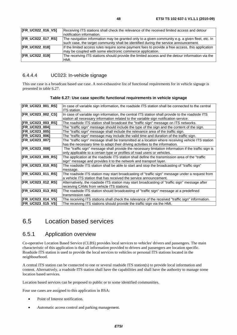
ETSI
ETSI TS 102 637-1 V1.1.1 (2010-09)48
[FR_UC022_016_VS] Receiving ITS stations shall check the relevance of the received limited access and detour notification information.
[FR_UC022_017_RS] The navigation information may be granted only to a given community e.g. a given fleet, etc. In such case, the target community shall be identified during the service announcement.
[FR_UC022_018] If the limited access rules require some payment fees to provide a free access, this application may be coupled with some electronic commerce application.
[FR_UC022_019] The receiving ITS stations should provide the limited access and the detour information via the HMI.
6.4.4.4 UC023: In-vehicle signage
This use case is a broadcast based use case. A non-exhaustive list of functional requirements for in vehicle signage is presented in table 6.27.
Table 6.27: Use case specific functional requirements in vehicle signage
[FR_UC023_001_RS] In case of variable sign information, the roadside ITS station shall be connected to the central ITS station.
[FR_UC023_002_CS] In case of variable sign information, the central ITS station shall provide to the roadside ITS station all necessary information related to the variable sign notification service.
[FR_UC023_003_RS] The roadside ITS station shall broadcast the "traffic sign" message on ITS networks. [FR_UC023_004] The "traffic sign" message should include the type of the sign and the content of the sign. [FR_UC023_005] The "traffic sign" message shall include the relevance area of the traffic sign. [FR_UC023_006] The "traffic sign" message may include the valid time and duration of the traffic sign. [FR_UC023_007] The "traffic sign" message shall be transmitted at a location where receiving vehicle ITS station
has the necessary time to adapt their driving activities to the information. [FR_UC023_008] The "traffic sign" message shall provide the necessary limitation information if the traffic sign is
only applicable to a certain type or profiles of road users or vehicles. [FR_UC023_009_RS] The application at the roadside ITS station shall define the transmission area of the "traffic
sign" message and provides it to the network and transport layer. [FR_UC023_010_RS] The roadside ITS station shall be able to start and stop the broadcasting of "traffic sign"
message. [FR_UC023_011_RS] The roadside ITS station may start broadcasting of "traffic sign" message under a request from
a vehicle ITS station that has received the service announcement. [FR_UC023_012_RS] Alternatively, the roadside ITS station may start broadcasting of "traffic sign" message after
receiving CAMs from vehicle ITS stations. [FR_UC023_013_RS] The roadside ITS station should broadcasting of "traffic sign" message at a predefined
transmission rate. [FR_UC023_014_VS] The receiving ITS stations shall check the relevance of the received "traffic sign" information. [FR_UC023_015_VS] The receiving ITS stations should provide the traffic sign via the HMI.
6.5 Location based services
6.5.1 Application overview
Co-operative Location Based Service (CLBS) provides local services to vehicles' drivers and passengers. The main characteristic of this application is that all information provided to drivers and passengers are location specific. Roadside ITS station is used to provide the local services to vehicles or personal ITS stations located in the neighbourhood.
A central ITS station can be connected to one or several roadside ITS station(s) to provide local information and content. Alternatively, a roadside ITS station shall have the capabilities and shall have the authority to manage some location based services.
Location based services can be proposed to public or to some identified communities.
Four use cases are assigned to this application in BSA:
• Point of Interest notification.
• Automatic access control and parking management.

ETSI
ETSI TS 102 637-1 V1.1.1 (2010-09)49
• ITS local electronic commerce.
• Media downloading.
6.5.2 Application functional summary and flow diagram
The service announcement and the possibility for a receiving vehicle ITS station to request the broadcasting of location based information e.g. the local points of interest, are the same as described on the figure 6.4. However in CLBS, the transaction may continue if the service persists, e.g. electronic commerce or some media downloading are requested by the in-vehicle ITS station application. This second part of the transaction is now described on the figure 6.5.
1) Upon reception of a broadcasted PoI message from the ITS station providing PoI services, the lower layers delivers the PoI to the facilities layer.
2) The facilities layer process the received PoI message and decides whether deliver the information to the application. Alternatively, the facilities layer can also be instructed by the application layer beforehand on the behaviour to follow in such circumstance.
3) The facilities layer issues the received PoI information to the application layer.
4) Application analyses the PoIs dynamic information and decides whether to inform the vehicle driver/passenger of one or several local PoIs.
5) The application layer provides to the driver/passenger the relevant PoIs' information.
6) The user decides whether to initiate an electronic transaction to one or several proposed local services.
7) In case that the user confirms to initiate an electronic commerce (EC) transaction, this one issues an EC request to its application layer.
8) Upon reception of its user EC request, the relevant application constructs the EC initiation message.
9) Application layer issues the EC message to the facilities layer and a request to establish a session between the local vehicle ITS station and the remote ITS station that broadcasted PoIs information.
10) The facilities layer processes the application layer request adding complementary data to the EC message if necessary.
11) The facilities layer issues an "open session" request to lower layers indicating the address of the requesting ITS station at the originating station of PoIs broadcasting.
12) Lower layer processing of the EC message. The lower layers establish the requested session with the remote ITS station using the assigned communication profile. When the session is established, the packets are transmitted to the roadside ITS station.
13) Transmission of packets between vehicle ITS station and the remote ITS station via the assigned access technology.
14) Upon reception of packets, the lower layer of the remote ITS station extract the packets for establishing the required session and EC initiation message.
15) The session establishment request and the received EC initiation message are transferred to the facilities layer by the network and transport layer.
16) The facilities layer of the remote ITS station establishes the requested session and extract the EC message.
17) The facilities layer issues a received message indication to the relevant application and provide EC initiation message to the application.
18) The relevant application establishes the EC transaction with its request station.
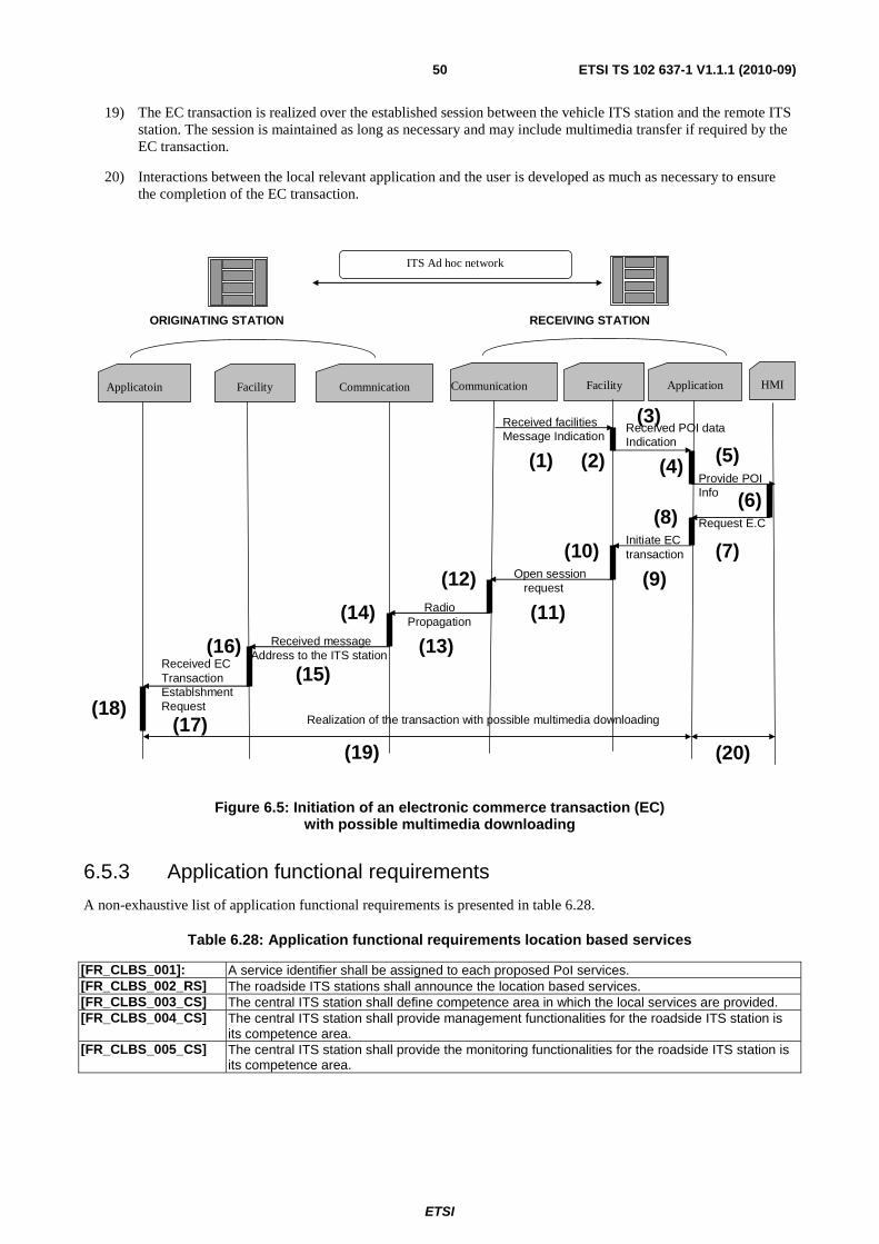
ETSI
ETSI TS 102 637-1 V1.1.1 (2010-09)50
19) The EC transaction is realized over the established session between the vehicle ITS station and the remote ITS station. The session is maintained as long as necessary and may include multimedia transfer if required by the EC transaction.
20) Interactions between the local relevant application and the user is developed as much as necessary to ensure the completion of the EC transaction.
Applicatoin
ORIGINATING STATION
Facility Commnication Communication Facility Application
RECEIVING STATION
HMI
ITS Ad hoc network
Received facilitiesMessage Indication
Received POI dataIndication
Provide POIInfo
Request E.CInitiate ECtransaction
Open session request
Radio Propagation
Received messageAddress to the ITS station
Received ECTransactionEstablshmentRequest
Realization of the transaction with possible multimedia downloading
(1) (2)
(3)
(4) (5)
(6)
(7)
(8)
(9)(10)
(11)
(12)
(13)
(14)
(15)(16)
(17)(18)
(19) (20)
Figure 6.5: Initiation of an electronic commerce transaction (EC) with possible multimedia downloading
6.5.3 Application functional requirements
A non-exhaustive list of application functional requirements is presented in table 6.28.
Table 6.28: Application functional requirements location based services
[FR_CLBS_001]: A service identifier shall be assigned to each proposed PoI services. [FR_CLBS_002_RS] The roadside ITS stations shall announce the location based services. [FR_CLBS_003_CS] The central ITS station shall define competence area in which the local services are provided. [FR_CLBS_004_CS] The central ITS station shall provide management functionalities for the roadside ITS station is
its competence area. [FR_CLBS_005_CS] The central ITS station shall provide the monitoring functionalities for the roadside ITS station is
its competence area.
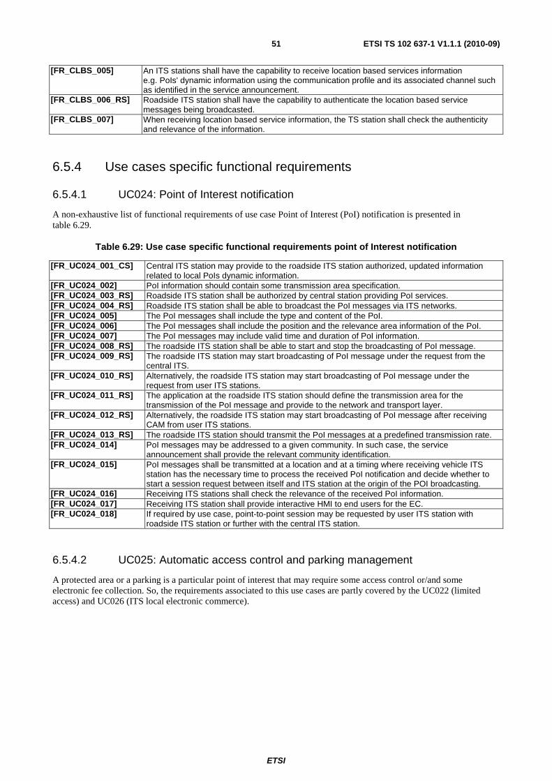
ETSI
ETSI TS 102 637-1 V1.1.1 (2010-09)51
[FR_CLBS_005] An ITS stations shall have the capability to receive location based services information e.g. PoIs' dynamic information using the communication profile and its associated channel such as identified in the service announcement.
[FR_CLBS_006_RS] Roadside ITS station shall have the capability to authenticate the location based service messages being broadcasted.
[FR_CLBS_007] When receiving location based service information, the TS station shall check the authenticity and relevance of the information.
6.5.4 Use cases specific functional requirements
6.5.4.1 UC024: Point of Interest notification
A non-exhaustive list of functional requirements of use case Point of Interest (PoI) notification is presented in table 6.29.
Table 6.29: Use case specific functional requirements point of Interest notification
[FR_UC024_001_CS] Central ITS station may provide to the roadside ITS station authorized, updated information related to local PoIs dynamic information.
[FR_UC024_002] PoI information should contain some transmission area specification. [FR_UC024_003_RS] Roadside ITS station shall be authorized by central station providing PoI services. [FR_UC024_004_RS] Roadside ITS station shall be able to broadcast the PoI messages via ITS networks. [FR_UC024_005] The PoI messages shall include the type and content of the PoI. [FR_UC024_006] The PoI messages shall include the position and the relevance area information of the PoI. [FR_UC024_007] The PoI messages may include valid time and duration of PoI information. [FR_UC024_008_RS] The roadside ITS station shall be able to start and stop the broadcasting of PoI message. [FR_UC024_009_RS] The roadside ITS station may start broadcasting of PoI message under the request from the
central ITS. [FR_UC024_010_RS] Alternatively, the roadside ITS station may start broadcasting of PoI message under the
request from user ITS stations. [FR_UC024_011_RS] The application at the roadside ITS station should define the transmission area for the
transmission of the PoI message and provide to the network and transport layer. [FR_UC024_012_RS] Alternatively, the roadside ITS station may start broadcasting of PoI message after receiving
CAM from user ITS stations. [FR_UC024_013_RS] The roadside ITS station should transmit the PoI messages at a predefined transmission rate. [FR_UC024_014] PoI messages may be addressed to a given community. In such case, the service
announcement shall provide the relevant community identification. [FR_UC024_015] PoI messages shall be transmitted at a location and at a timing where receiving vehicle ITS
station has the necessary time to process the received PoI notification and decide whether to start a session request between itself and ITS station at the origin of the POI broadcasting.
[FR_UC024_016] Receiving ITS stations shall check the relevance of the received PoI information. [FR_UC024_017] Receiving ITS station shall provide interactive HMI to end users for the EC. [FR_UC024_018] If required by use case, point-to-point session may be requested by user ITS station with
roadside ITS station or further with the central ITS station.
6.5.4.2 UC025: Automatic access control and parking management
A protected area or a parking is a particular point of interest that may require some access control or/and some electronic fee collection. So, the requirements associated to this use cases are partly covered by the UC022 (limited access) and UC026 (ITS local electronic commerce).
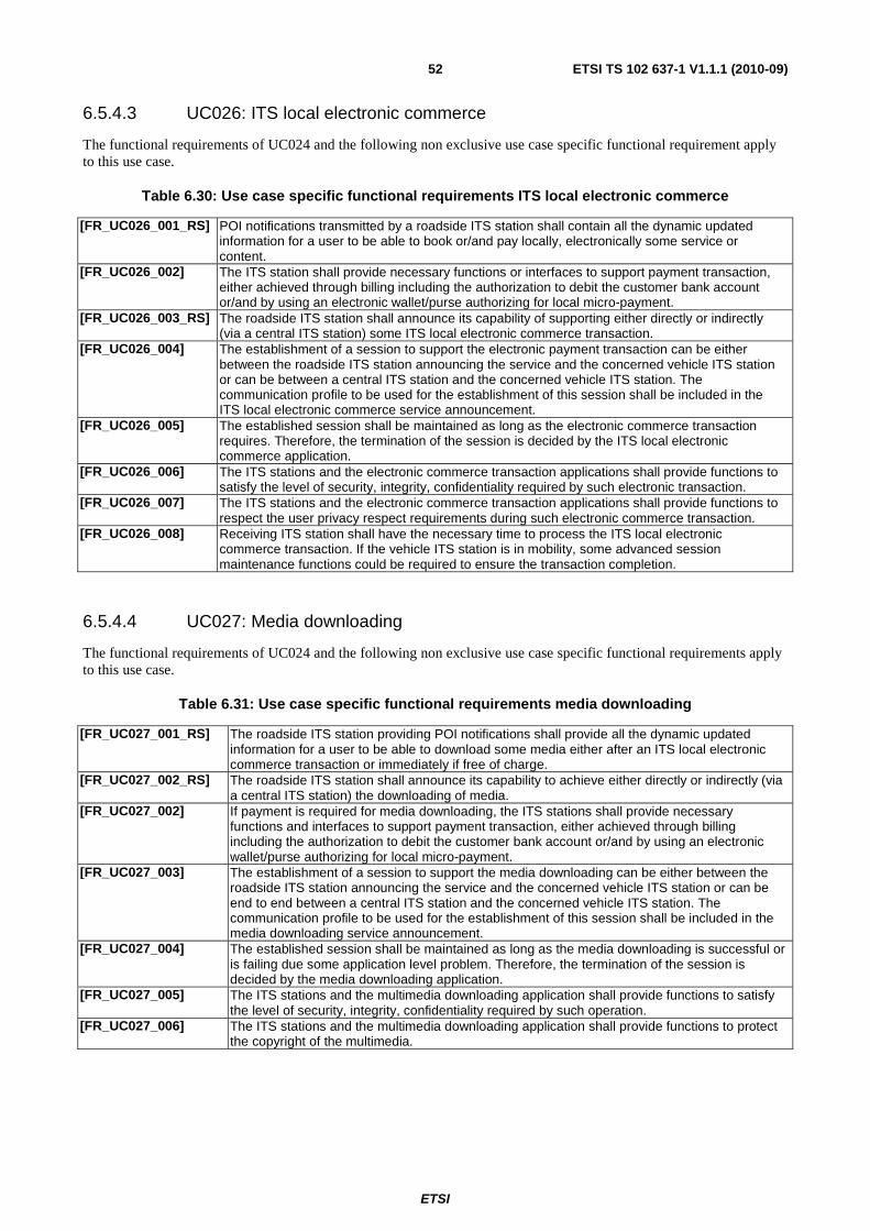
ETSI
ETSI TS 102 637-1 V1.1.1 (2010-09)52
6.5.4.3 UC026: ITS local electronic commerce
The functional requirements of UC024 and the following non exclusive use case specific functional requirement apply to this use case.
Table 6.30: Use case specific functional requirements ITS local electronic commerce
[FR_UC026_001_RS] POI notifications transmitted by a roadside ITS station shall contain all the dynamic updated information for a user to be able to book or/and pay locally, electronically some service or content.
[FR_UC026_002] The ITS station shall provide necessary functions or interfaces to support payment transaction, either achieved through billing including the authorization to debit the customer bank account or/and by using an electronic wallet/purse authorizing for local micro-payment.
[FR_UC026_003_RS] The roadside ITS station shall announce its capability of supporting either directly or indirectly (via a central ITS station) some ITS local electronic commerce transaction.
[FR_UC026_004] The establishment of a session to support the electronic payment transaction can be either between the roadside ITS station announcing the service and the concerned vehicle ITS station or can be between a central ITS station and the concerned vehicle ITS station. The communication profile to be used for the establishment of this session shall be included in the ITS local electronic commerce service announcement.
[FR_UC026_005] The established session shall be maintained as long as the electronic commerce transaction requires. Therefore, the termination of the session is decided by the ITS local electronic commerce application.
[FR_UC026_006] The ITS stations and the electronic commerce transaction applications shall provide functions to satisfy the level of security, integrity, confidentiality required by such electronic transaction.
[FR_UC026_007] The ITS stations and the electronic commerce transaction applications shall provide functions to respect the user privacy respect requirements during such electronic commerce transaction.
[FR_UC026_008] Receiving ITS station shall have the necessary time to process the ITS local electronic commerce transaction. If the vehicle ITS station is in mobility, some advanced session maintenance functions could be required to ensure the transaction completion.
6.5.4.4 UC027: Media downloading
The functional requirements of UC024 and the following non exclusive use case specific functional requirements apply to this use case.
Table 6.31: Use case specific functional requirements media downloading
[FR_UC027_001_RS] The roadside ITS station providing POI notifications shall provide all the dynamic updated information for a user to be able to download some media either after an ITS local electronic commerce transaction or immediately if free of charge.
[FR_UC027_002_RS] The roadside ITS station shall announce its capability to achieve either directly or indirectly (via a central ITS station) the downloading of media.
[FR_UC027_002] If payment is required for media downloading, the ITS stations shall provide necessary functions and interfaces to support payment transaction, either achieved through billing including the authorization to debit the customer bank account or/and by using an electronic wallet/purse authorizing for local micro-payment.
[FR_UC027_003] The establishment of a session to support the media downloading can be either between the roadside ITS station announcing the service and the concerned vehicle ITS station or can be end to end between a central ITS station and the concerned vehicle ITS station. The communication profile to be used for the establishment of this session shall be included in the media downloading service announcement.
[FR_UC027_004] The established session shall be maintained as long as the media downloading is successful or is failing due some application level problem. Therefore, the termination of the session is decided by the media downloading application.
[FR_UC027_005] The ITS stations and the multimedia downloading application shall provide functions to satisfy the level of security, integrity, confidentiality required by such operation.
[FR_UC027_006] The ITS stations and the multimedia downloading application shall provide functions to protect the copyright of the multimedia.

ETSI
ETSI TS 102 637-1 V1.1.1 (2010-09)53
[FR_UC027_007] The ITS stations and the multimedia downloading application shall respect the required user privacy during the whole media downloading.
[FR_UC027_008] The vehicle ITS station shall have the necessary time to ensure the complete media downloading. If the vehicle ITS station is in mobility, some advanced session maintenance support could be required to ensure the complete media downloading.
[FR_UC027_009] The ITS station providing the multimedia downloading application shall provide the information on the size of the media for the usage of session management. The assigned communication profile performance may take into account this size.
6.6 Communities services
6.6.1 Application overview
Communities Services (ComS) application is mainly characterized by the services provided by a community service provider to multiple ITS stations belonging to a given community. The service provider of such community service may be logistic companies, insurance companies, OEM service provider, or private community services (club, association, cities, etc.). Depending on the use case, the messages exchanged between the user ITS stations and service provider ITS stations may contain sensitive, driver-specific data. Alternatively, a local central ITS station plays the role of the local community service provider giving access to Internet. However, this local central ITS station is not necessarily the actor who operates the whole back end system platform, among which most are web based services.
NOTE: A global access to Internet using an ISP contract at the client side is not considered in this application.
Three user cases are assigned to this application in BSA.
• UC028: Insurance and financial services;
• UC029: Fleet management;
• UC030: Loading zone management.
6.6.2 Application flow diagram
Figure 6.6 shows the flows necessary for a user of a given community to get access to Internet as a visitor of the community.
1) Service announcement broadcasted by the roadside ITS station announces its local capability to offer an Internet access, the provided community services together with the community identification.
2) The user ITS station analyses the received service announcement and decides on the relevance of and the interest to this proposed services. If one of the local users (driver or passenger) belongs to the concerned community, a visitor Internet access is proposed to the user.
3) If one of the users is interested by this proposed internet access and the community services, this one provides all the necessary information/evidence of its user profile information within the concerned community to the local central ITS station.
4) The local central ITS station verifies the user profile with regards to the managed community and if valid, grants him access to Internet.
5) The authorized access to Internet as a visitor of the community is acknowledged to the user via its vehicle ITS station.
6) The vehicle ITS station may establish an Internet session with any central ITS station located on Internet. An adapted communication profile is used for this purpose.
7) The Internet session can stay operational as long as necessary for the user in the vehicle ITS station to achieve its community services.
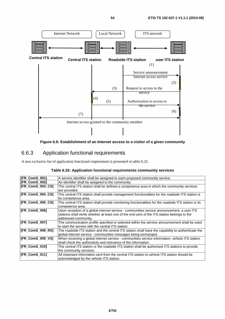
ETSI
ETSI TS 102 637-1 V1.1.1 (2010-09)54
Figure 6.6: Establishment of an Internet access to a visitor of a given community
6.6.3 Application functional requirements
A non exclusive list of application functional requirement is presented in table 6.32.
Table 6.32: Application functional requirements community services
[FR_ComS_001] A service identifier shall be assigned to each proposed community service. [FR_ComS_002] An identifier shall be assigned to the community. [FR_ComS_003_CS] The central ITS station shall be defined a competence area in which the community services
are provided. [FR_ComS_004_CS] The central ITS station shall provide management functionalities for the roadside ITS station is
its competence area. [FR_ComS_005_CS] The central ITS station shall provide monitoring functionalities for the roadside ITS station is its
competence area. [FR_ComS_006] Upon reception of a global internet service - communities service announcement, a user ITS
stations shall verify whether at least one of the end uers of the ITS station belongs to the addressed community.
[FR_ComS_007] The communication profile specified or selected within the service announcement shall be used to start the service with the central ITS station.
[FR_ComS_008_RS] The roadside ITS station and the central ITS station shall have the capability to authenticate the global internet service - communities messages being exchanged.
[FR_ComS_009_VS] When receiving a global internet service - communities service information, vehicle ITS station shall check the authenticity and relevance of the information.
[FR_ComS_010] The central ITS station or the roadside ITS station shall be authorized ITS stations to provide the community services.
[FR_ComS_011] All important information sent from the central ITS station to vehicle ITS station should be acknowledged by the vehicle ITS station.
Central ITS station
(1)
Internet Network
(2)
(3)
(4) (5)
(6)(7)
Local Network ITS network
Central ITS station Roadside ITS station user ITS station
Service announcement Internet access service
Request to access to the service
Authorization to access to the service
Internet access granted to the community member
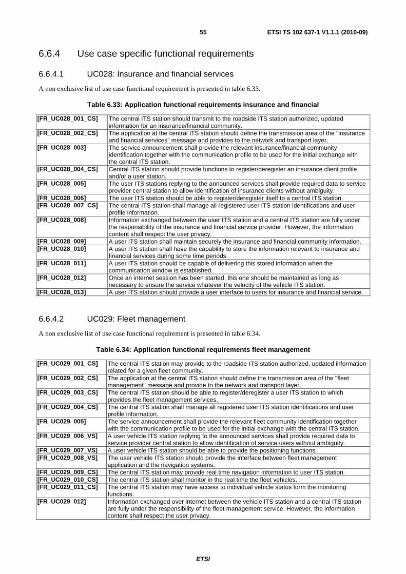
ETSI
ETSI TS 102 637-1 V1.1.1 (2010-09)55
6.6.4 Use case specific functional requirements
6.6.4.1 UC028: Insurance and financial services
A non exclusive list of use case functional requirement is presented in table 6.33.
Table 6.33: Application functional requirements insurance and financial
[FR_UC028_001_CS] The central ITS station should transmit to the roadside ITS station authorized, updated information for an insurance/financial community.
[FR_UC028_002_CS] The application at the central ITS station should define the transmission area of the "insurance and financial services" message and provides to the network and transport layer.
[FR_UC028_003] The service announcement shall provide the relevant insurance/financial community identification together with the communication profile to be used for the initial exchange with the central ITS station.
[FR_UC028_004_CS] Central ITS station should provide functions to register/deregister an insurance client profile and/or a user station.
[FR_UC028_005] The user ITS stations replying to the announced services shall provide required data to service provider central station to allow identification of insurance clients without ambiguity.
[FR_UC028_006] The user ITS station should be able to register/deregister itself to a central ITS station. [FR_UC028_007_CS] The central ITS station shall manage all registered user ITS station identifications and user
profile information. [FR_UC028_008] Information exchanged between the user ITS station and a central ITS station are fully under
the responsibility of the insurance and financial service provider. However, the information content shall respect the user privacy.
[FR_UC028_009] A user ITS station shall maintain securely the insurance and financial community information. [FR_UC028_010] A user ITS station shall have the capability to store the information relevant to insurance and
financial services during some time periods. [FR_UC028_011] A user ITS station should be capable of delivering this stored information when the
communication window is established. [FR_UC028_012] Once an internet session has been started, this one should be maintained as long as
necessary to ensure the service whatever the velocity of the vehicle ITS station. [FR_UC028_013] A user ITS station should provide a user interface to users for insurance and financial service.
6.6.4.2 UC029: Fleet management
A non exclusive list of use case functional requirement is presented in table 6.34.
Table 6.34: Application functional requirements fleet management
[FR_UC029_001_CS] The central ITS station may provide to the roadside ITS station authorized, updated information related for a given fleet community.
[FR_UC029_002_CS] The application at the central ITS station should define the transmission area of the "fleet management" message and provide to the network and transport layer.
[FR_UC029_003_CS] The central ITS station should be able to register/deregister a user ITS station to which provides the fleet management services.
[FR_UC029_004_CS] The central ITS station shall manage all registered user ITS station identifications and user profile information.
[FR_UC029_005] The service announcement shall provide the relevant fleet community identification together with the communication profile to be used for the initial exchange with the central ITS station.
[FR_UC029_006_VS] A user vehicle ITS station replying to the announced services shall provide required data to service provider central station to allow identification of service users without ambiguity.
[FR_UC029_007_VS] A user vehicle ITS station should be able to provide the positioning functions. [FR_UC029_008_VS] The user vehicle ITS station should provide the interface between fleet management
application and the navigation systems. [FR_UC029_009_CS] The central ITS station may provide real time navigation information to user ITS station. [FR_UC029_010_CS] The central ITS station shall monitor in the real time the fleet vehicles. [FR_UC029_011_CS] The central ITS station may have access to individual vehicle status form the monitoring
functions. [FR_UC029_012] Information exchanged over internet between the vehicle ITS station and a central ITS station
are fully under the responsibility of the fleet management service. However, the information content shall respect the user privacy.

ETSI
ETSI TS 102 637-1 V1.1.1 (2010-09)56
[FR_UC029_013_VS] A user vehicle ITS station shall maintain securely the fleet community identification. [FR_UC029_014_VS] A user vehicle ITS station in the fleet should report its status changes to the central ITS station. [FR_UC029_015_CS] The central ITS station should be able to inform the status changes to a vehicle ITS stations in
the fleet. [FR_UC029_016_CS] If required by the fleet management, the central ITS station may be able to control remotely
vehicle ITS station. [FR_UC029_017] Once an internet session has been started, this one should be maintained as long as
necessary to insure the service whatever the velocity of the vehicle ITS station. This may be achieved by assigning a global communication profile or insuring the roaming between several communication profiles.
[FR_UC029_018_VS] A user vehicle ITS station should have the capability to store information relevant to fleet management services during some time periods when the communications are not possible.
[FR_UC029_019_VS] A vehicle ITS station should be capable of delivering this stored information as soon as a communication window is opened.
[FR_UC029_020_CS] If required by the fleet management, the application at the central ITS station shall be able to send request to other applications at other ITS stations e.g. parking access, PoI notifications that provide relevant information for fleet management purpose.
[FR_UC029_021_VS] A user vehicle ITS station shall provide a user interface for fleet management. [FR_UC029_022_VS] Vehicle ITS station should have access to the in vehicle system in order to retrieve vehicle
status information.
6.6.4.3 UC030: Loading zone management
A non exclusive list of use case functional requirement is presented in table 6.35.
Table 6.35: Application functional requirements loading zone management
[FR_UC030_001_CS] The central ITS station should provide to the roadside ITS station authorized, updated information for the loading zone management of a given community.
[FR_UC030_002_CS] The application at the central ITS station shall define the transmission area of the "loading zone management" message and provide it to the network and transport layer.
[FR_UC030_003] The service announcement shall provide the relevant loading zone management community identification accompanied with the communication profile to be used for the initial exchange with the central ITS station.
[FR_UC030_004] The user ITS stations replying to the announced services shall provide required data to service provider central station to allow identification of service users without ambiguity.
[FR_UC030_005] Information exchanged over internet between the vehicles ITS station and a central ITS station are fully under the responsibility of the loading zone management service. However, the information content shall respect the user privacy.
[FR_UC030_006_VS] A vehicle ITS station shall maintain securely the community identification in charge of the loading zone management.
[FR_UC030_007] Once an Internet session has been started, this one should be maintained as long as necessary to insure the service whatever the velocity of the vehicle ITS station. This may be achieved by assigning a global communication profile or insuring the roaming between several communication profiles.
6.7 ITS station life cycle management
6.7.1 Application overview
This application (LCM) provides the ITS station life cycle management services, including vehicle ITS stations and roadside ITS stations.
The services can be provided either by a central ITS station via generic access networks or by authorized decentralized central ITS station locally connected to a roadside ITS station. Vehicle ITS stations are informed of the service availability by receiving service announcement from the roadside ITS station. Then, a point-to-point session is established with roadside ITS station or with the service provider central ITS station via a generic access network or ITS networks in order to download and update the station software and data.
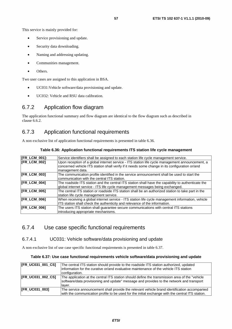
ETSI
ETSI TS 102 637-1 V1.1.1 (2010-09)57
This service is mainly provided for:
• Service provisioning and update.
• Security data downloading.
• Naming and addressing updating.
• Communities management.
• Others.
Two user cases are assigned to this application in BSA.
• UC031:Vehicle software/data provisioning and update.
• UC032: Vehicle and RSU data calibration.
6.7.2 Application flow diagram
The application functional summary and flow diagram are identical to the flow diagram such as described in clause 6.6.2.
6.7.3 Application functional requirements
A non exclusive list of application functional requirements is presented in table 6.36.
Table 6.36: Application functional requirements ITS station life cycle management
[FR_LCM_001]: Service identifiers shall be assigned to each station life cycle management service. [FR_LCM_002] Upon reception of a global internet service - ITS station life cycle management announcement, a
concerned vehicle ITS station shall verify if it needs some change in its configuration or/and management data.
[FR_LCM_003] The communication profile identified in the service announcement shall be used to start the communication with the central ITS station.
[FR_LCM_004] The roadside ITS station and the central ITS station shall have the capability to authenticate the global internet service - ITS life cycle management messages being exchanged.
[FR_LCM_005] The central ITS station or roadside ITS station shall be an authorized station to take part in the station life cycle management service.
[FR_LCM_006] When receiving a global internet service - ITS station life cycle management information, vehicle ITS station shall check the authenticity and relevance of the information.
[FR_LCM_006] The users ITS station shall guarantee secure communications with central ITS stations introducing appropriate mechanisms.
6.7.4 Use case specific functional requirements
6.7.4.1 UC031: Vehicle software/data provisioning and update
A non exclusive list of use case specific functional requirements is presented in table 6.37.
Table 6.37: Use case functional requirements vehicle software/data provisioning and update
[FR_UC031_001_CS] The central ITS station should provide to the roadside ITS station authorized, updated information for the curative or/and evaluative maintenance of the vehicle ITS station configuration.
[FR_UC031_002_CS] The application at the central ITS station should define the transmission area of the "vehicle software/data provisioning and update" message and provides to the network and transport layer.
[FR_UC031_003] The service announcement shall provide the relevant vehicle brand identification accompanied with the communication profile to be used for the initial exchange with the central ITS station.
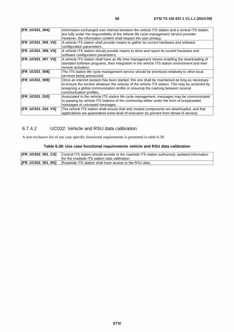
ETSI
ETSI TS 102 637-1 V1.1.1 (2010-09)58
[FR_UC031_004] Information exchanged over internet between the vehicle ITS station and a central ITS station are fully under the responsibility of the vehicle life cycle management service provider. However, the information content shall respect the user privacy.
[FR_UC031_005_VS] A vehicle ITS station shall provide means to gather its current hardware and software configuration parameters.
[FR_UC031_006_VS] A vehicle ITS station should provide means to store and report its current hardware and software configuration parameters.
[FR_UC031_007_VS] A vehicle ITS station shall have an life time management means enabling the downloading of standard software programs, their integration in the vehicle ITS station environment and their remote activation.
[FR_UC031_008] The ITS station life cycle management service should be prioritized relatively to other local services being announced.
[FR_UC031_009] Once an internet session has been started, this one shall be maintained as long as necessary to ensure the service whatever the velocity of the vehicle ITS station. This may be achieved by assigning a global communication profile or ensuring the roaming between several communication profiles.
[FR_UC031_010] Associated to the vehicle ITS station life cycle management, messages may be communicated to passing by vehicle ITS stations of the community either under the form of broadcasted messages or unicasted messages.
[FR_UC031_010_VS] The vehicle ITS station shall ensure that only trusted components are downloaded, and that applications are guaranteed some level of execution (to prevent from denial of service).
6.7.4.2 UC032: Vehicle and RSU data calibration
A non exclusive list of use case specific functional requirements is presented in table 6.38.
Table 6.38: Use case functional requirements vehicle and RSU data calibration
[FR_UC032_001_CS] Central ITS station should provide to the roadside ITS station authorized, updated information for the roadside ITS station data calibration.
[FR_UC032_001_RS] Roadside ITS station shall have access to the RSU data.

ETSI
ETSI TS 102 637-1 V1.1.1 (2010-09)59
Annex A (informative): Bibliography
• Car to car communication consortium (C2CCC)
NOTE: Available at www.car-to-car.org.
• European ITS FRAME architecture D3.1: "Functional Viewpoint".
• CVIS project deliverable D.FOAM.2.2: "Final System Requirements".
• CVIS project deliverable D.CVIS.2.2: "Use Cases and System Requirements".
• CVIS project deliverable D.CVIS.3.3: "Architecture and System Specifications"
• COMeSafety specific support action:" COMeSafety European ITS Communication Architecture".
• Vehicle Infrastructure Integration (VII): "VII Architecture and Functional Requirements V1.1".

ETSI
ETSI TS 102 637-1 V1.1.1 (2010-09)60
History
Document history
V1.1.1 September 2010 Publication