
TS 102 226 - V9.2.0 - Smart Cards; Remote APDU structure for UICC
43
ETSI TS 102 226 V9.2.0 (2010-04) Technical Specification Smart Cards; Remote APDU structure for UICC based applications (Release 9)
Transcript of TS 102 226 - V9.2.0 - Smart Cards; Remote APDU structure for UICC

ETSI TS 102 226 V9.2.0 (2010-04)
Technical Specification
Smart Cards;Remote APDU structure for UICC based applications
(Release 9)

ETSI
ETSI TS 102 226 V9.2.0 (2010-04)2Release 9
Reference RTS/SCP-T02850v920
Keywords protocol, smart card
ETSI
650 Route des Lucioles F-06921 Sophia Antipolis Cedex - FRANCE
Tel.: +33 4 92 94 42 00 Fax: +33 4 93 65 47 16
Siret N° 348 623 562 00017 - NAF 742 C
Association à but non lucratif enregistrée à la Sous-Préfecture de Grasse (06) N° 7803/88
Important notice
Individual copies of the present document can be downloaded from: http://www.etsi.org
The present document may be made available in more than one electronic version or in print. In any case of existing or perceived difference in contents between such versions, the reference version is the Portable Document Format (PDF).
In case of dispute, the reference shall be the printing on ETSI printers of the PDF version kept on a specific network drive within ETSI Secretariat.
Users of the present document should be aware that the document may be subject to revision or change of status. Information on the current status of this and other ETSI documents is available at
http://portal.etsi.org/tb/status/status.asp
If you find errors in the present document, please send your comment to one of the following services: http://portal.etsi.org/chaircor/ETSI_support.asp
Copyright Notification
No part may be reproduced except as authorized by written permission. The copyright and the foregoing restriction extend to reproduction in all media.
© European Telecommunications Standards Institute 2010.
All rights reserved.
DECTTM, PLUGTESTSTM, UMTSTM, TIPHONTM, the TIPHON logo and the ETSI logo are Trade Marks of ETSI registered for the benefit of its Members.
3GPPTM is a Trade Mark of ETSI registered for the benefit of its Members and of the 3GPP Organizational Partners. LTE™ is a Trade Mark of ETSI currently being registered
for the benefit of its Members and of the 3GPP Organizational Partners. GSM® and the GSM logo are Trade Marks registered and owned by the GSM Association.
ETSI
ETSI TS 102 226 V9.2.0 (2010-04)3Release 9
Contents
Intellectual Property Rights ................................................................................................................................ 5
Foreword ............................................................................................................................................................. 5
1 Scope ........................................................................................................................................................ 6
2 References ................................................................................................................................................ 6
2.1 Normative references ......................................................................................................................................... 6
2.2 Informative references ........................................................................................................................................ 8
3 Definitions and abbreviations ................................................................................................................... 8
3.1 Definitions .......................................................................................................................................................... 8
3.2 Abbreviations ..................................................................................................................................................... 8
4 Overview of remote management ............................................................................................................ 9
5 Remote APDU format ............................................................................................................................ 10
5.1 Compact Remote Application data format ....................................................................................................... 10
5.1.1 Compact Remote command structure ......................................................................................................... 10
5.1.2 Compact Remote response structure ........................................................................................................... 10
5.2 Expanded Remote Application data format ...................................................................................................... 10
5.2.1 Expanded Remote command structure ....................................................................................................... 10
5.2.1.1 C-APDU TLV ....................................................................................................................................... 11
5.2.1.2 Immediate Action TLV ......................................................................................................................... 12
5.2.1.3 Error Action TLV .................................................................................................................................. 13
5.2.1.4 Script Chaining TLV ............................................................................................................................. 13
5.2.2 Expanded Remote response structure ......................................................................................................... 14
5.3 Automatic application data format detection .................................................................................................... 17
6 Security parameters assigned to applications ......................................................................................... 17
6.1 Minimum Security Level (MSL) ...................................................................................................................... 17
6.2 Access domain .................................................................................................................................................. 17
7 Remote File Management (RFM) .......................................................................................................... 18
7.1 Commands ........................................................................................................................................................ 18
7.2 UICC Shared File System Remote File Management ...................................................................................... 19
7.3 ADF Remote File Management ........................................................................................................................ 19
7.4 RFM implementation over HTTPS .................................................................................................................. 19
8 Remote Application Management (RAM) ............................................................................................. 19
8.1 Remote application management application behaviour .................................................................................. 20
8.2 Commands coding and description................................................................................................................... 20
8.2.1 Commands .................................................................................................................................................. 21
8.2.1.1 DELETE ............................................................................................................................................... 21
8.2.1.2 SET STATUS ....................................................................................................................................... 21
8.2.1.3 INSTALL .............................................................................................................................................. 21
8.2.1.3.1 INSTALL [for load] ........................................................................................................................ 21
8.2.1.3.2 INSTALL [for install] ..................................................................................................................... 22
8.2.1.4 LOAD ................................................................................................................................................... 29
8.2.1.5 PUT KEY .............................................................................................................................................. 29
8.2.1.5.1 PUT KEY for AES .......................................................................................................................... 30
8.2.1.6 GET STATUS ....................................................................................................................................... 30
8.2.1.6.1 Menu parameters ............................................................................................................................. 30
8.2.1.7 GET DATA ........................................................................................................................................... 31
8.2.1.7.1 Void ................................................................................................................................................. 31
8.2.1.7.2 Extended Card resources information ............................................................................................. 31
8.2.1.8 STORE DATA ...................................................................................................................................... 32
8.3 RAM implementation over HTTPS .................................................................................................................. 32
9 Additional command for push ................................................................................................................ 33
9.1 Push command behaviour ................................................................................................................................ 33
ETSI
ETSI TS 102 226 V9.2.0 (2010-04)4Release 9
9.1.1 Request for open channel ............................................................................................................................ 33
9.1.2 Request for CAT_TP link establishment .................................................................................................... 33
9.1.3 Behaviour for responses .............................................................................................................................. 33
9.1.4 Request for TCP connection ....................................................................................................................... 33
9.1.5 Request for Identification Packet ................................................................................................................ 33
9.2 Commands coding ............................................................................................................................................ 33
9.2.1 Data for BIP channel opening ..................................................................................................................... 34
9.2.2 Data for CAT_TP link establishment.......................................................................................................... 34
9.2.3 Data for TCP connection opening ............................................................................................................... 35
9.2.4 Data for sending of Identification Packet ................................................................................................... 35
9.3 Closing of the BIP channel ............................................................................................................................... 36
10 Confidential application management .................................................................................................... 36
10.1 Confidential loading ......................................................................................................................................... 36
10.2 Additional application provider security .......................................................................................................... 37
10.3 Confidential setup of security domains ............................................................................................................ 37
10.4 Application personalisation in an APSD .......................................................................................................... 37
Annex A (normative): BER-TLV tags ................................................................................................ 38
Annex B (informative): RFM over HTTP Communication Flow ...................................................... 39
Annex C (informative): Change history ............................................................................................... 41
History .............................................................................................................................................................. 43
ETSI
ETSI TS 102 226 V9.2.0 (2010-04)5Release 9
Intellectual Property Rights IPRs essential or potentially essential to the present document may have been declared to ETSI. The information pertaining to these essential IPRs, if any, is publicly available for ETSI members and non-members, and can be found in ETSI SR 000 314: "Intellectual Property Rights (IPRs); Essential, or potentially Essential, IPRs notified to ETSI in respect of ETSI standards", which is available from the ETSI Secretariat. Latest updates are available on the ETSI Web server (http://webapp.etsi.org/IPR/home.asp).
Pursuant to the ETSI IPR Policy, no investigation, including IPR searches, has been carried out by ETSI. No guarantee can be given as to the existence of other IPRs not referenced in ETSI SR 000 314 (or the updates on the ETSI Web server) which are, or may be, or may become, essential to the present document.
Foreword This Technical Specification (TS) has been produced by ETSI Technical Committee Smart Card Platform (SCP).
It is based on work originally done in the 3GPP in TSG-terminals WG3 and ETSI SMG.
The contents of the present document are subject to continuing work within EP SCP and may change following formal EP SCP approval. If EP SCP modifies the contents of the present document, it will then be republished by ETSI with an identifying change of release date and an increase in version number as follows:
Version x.y.z
where:
x: the first digit:
0 early working draft;
1 presented to EP SCP for information;
2 presented to EP SCP for approval;
3 or greater indicates EP SCP approved document under change control.
y: the second digit is incremented for all changes of substance, i.e. technical enhancements, corrections, updates, etc.
z: the third digit is incremented when editorial only changes have been incorporated in the document.

ETSI
ETSI TS 102 226 V9.2.0 (2010-04)6Release 9
1 Scope The present document defines the remote management of the UICC based on any of the secured packet structures specified in TS 102 225 [1].
It specifies the APDU format for remote management.
• Furthermore the present document specifies: a set of commands coded according to this APDU structure and used in the remote file management on the UICC. This is based on TS 102 221 [2].
• A set of commands coded according to this APDU structure and used in the remote application management on the UICC. This is based on the GlobalPlatform Card Specifications.
2 References References are either specific (identified by date of publication and/or edition number or version number) or non-specific.
• For a specific reference, subsequent revisions do not apply.
• In the case of a reference to a TC SCP document, a non specific reference implicitly refers to the latest version of that document in the same Release as the present document.
• Non-specific reference may be made only to a complete document or a part thereof and only in the following cases:
- if it is accepted that it will be possible to use all future changes of the referenced document for the purposes of the referring document;
- for informative references.
Referenced documents which are not found to be publicly available in the expected location might be found at http://docbox.etsi.org/Reference.
NOTE: While any hyperlinks included in this clause were valid at the time of publication ETSI cannot guarantee their long term validity.
2.1 Normative references The following referenced documents are indispensable for the application of the present document. For dated references, only the edition cited applies. For non-specific references, the latest edition of the referenced document (including any amendments) applies.
[1] ETSI TS 102 225: "Smart Cards; Secured packet structure for UICC based applications".
[2] ETSI TS 102 221: "Smart Cards; UICC-Terminal interface; Physical and logical characteristics".
[3] ETSI TS 102 223: "Smart Cards; Card Application Toolkit (CAT)".
[4] GlobalPlatform: "GlobalPlatform Card Specification, Version 2.2" including "Errata and precision list" Version 0.2.
NOTE: See http://www.globalplatform.org/.
[5] ETSI TS 101 220: "Smart cards; ETSI numbering system for telecommunication application providers".
[6] ETSI TS 102 241: "Smart Cards; UICC Application Programming Interface (UICC API) for Java Card (TM)".

ETSI
ETSI TS 102 226 V9.2.0 (2010-04)7Release 9
[7] GlobalPlatform: "GlobalPlatform Card Specification Version 2.0.1".
NOTE: See http://www.globalplatform.org/.
[8] Void.
[9] ETSI TS 102 222: "Integrated Circuit Cards (ICC); Administrative commands for telecommunications applications".
[10] ETSI TS 123 048: "Digital cellular telecommunications system (Phase 2+); Universal Mobile Telecommunications System (UMTS); Security mechanisms for the (U)SIM application toolkit; Stage 2 (3GPP TS 23.048, Release 5)".
[11] ETSI TS 102 127: "Smart Cards; Transport protocol for CAT applications; Stage 2".
[12] ETSI TS 143 019: "Digital cellular telecommunications system (Phase 2+); Subscriber Identity Module Application Programming Interface (SIM API) for Java Card; Stage 2 (3GPP TS 43.019 Release 5)".
[13] FIPS-197 (2001): "Advanced Encryption Standard (AES)".
NOTE: See http://csrc.nist.gov/publications/fips/index.html.
[14] NIST Special Publication 800-38A (2001): "Recommendation for Block Cipher Modes of Operation - Methods and Techniques".
NOTE: See http://csrc.nist.gov/publications/nistpubs/.
[15] NIST Special Publication 800-38B (2001): "Recommendation for Block Cipher Modes of Operation: The CMAC Mode for Authentication".
NOTE: See http://csrc.nist.gov/publications/nistpubs/.
[16] "GlobalPlatform Card UICC Configuration", Version 1.0.
NOTE: See http://www.globalplatform.org/.
[17] ETSI TS 102 588: "Smart Cards; Application invocation Application Programming Interface (API) by a UICC webserver for Java Card™ platform".
[18] GlobalPlatform: "GlobalPlatform Card Specification Version 2.2, Amendment A" Version 1.0 including "Errata and Precisions" Version 1.0.
NOTE: See http://www.globalplatform.org/.
[19] "GlobalPlatform Card Specification Version 2.2, Amendment B" Version 1.1.
NOTE: See http://www.globalplatform.org/.
[20] ETSI TS 102 483: "Smart cards; UICC-Terminal interface; Internet Protocol connectivity between UICC and terminal".
[21] ISO/IEC 8825-1: "Information technology - ASN.1 encoding rules: Specification of Basic Encoding Rules (BER), Canonical Encoding Rules (CER) and Distinguished Encoding Rules (DER)".
[22] GlobalPlatform: "GlobalPlatform Card Specification Version 2.2, Amendment C: Contactless Services" Version 1.0.
NOTE: See http://www.globalplatform.org/.
[23] ETSI TS 102 622: "Smart card; UICC-Contactless Front-end (CLF) Interface, Host Controller Interface (HCI)".

ETSI
ETSI TS 102 226 V9.2.0 (2010-04)8Release 9
2.2 Informative references The following referenced documents are not essential to the use of the present document but they assist the user with regard to a particular subject area. For non-specific references, the latest version of the referenced document (including any amendments) applies.
Not applicable.
3 Definitions and abbreviations
3.1 Definitions For the purposes of the present document, the terms and definitions given below and those in TS 102 225 [1] and TS 101 220 [5] apply.
Controlling Authority Security Domain (CASD): on-card controlling entity representing an off card trusted third party
NOTE: It provides services to confidentially load or generate Secure Channel keys of the APSD.
3.2 Abbreviations For the purposes of the present document, the abbreviations given in TS 102 225 [1] and the following apply:
ACK ACKnowledge ADD Access Domain Data ADF Application Data File ADP Access Domain Parameter AES Advanced Encryption Standard AID Application IDentifier APDU Application Protocol Data Unit API Application Programming Interface APSD Application Provider Security Domain BER-TLV Basic Encoding Rules - Tag, Length, Value BIP Bearer Independent Protocol C-APDU Command Application Protocol Data Unit CASD Controlling Authority Security Domain CBC Cell Broadcast Centre CLA Class CMAC Cipher-based Message Authentication Code DAP Data Authentication Pattern DEK Data Encryption Key DES Data Encryption Standard DF Directory File ECB Electronic Code Book EF Elementary File HTTP HyperText Transfer Protocol HTTPS HyperText Transfer Protocol Secure ICCID Integrated Circuit Card IDentification INS INStruction KIc Key and algorithm Identifier for ciphering KID Key and algorithm IDentifier for RC/CC/DS MAC Message Authentication Code MF Management Field MSL Minimum Security Level MSLD Minimum Security Level Data OTA Over The Air PDU Packet Data Unit

ETSI
ETSI TS 102 226 V9.2.0 (2010-04)9Release 9
RAM Remote Application Management R-APDU Response Application Protocol Data Unit RFM Remote File Management RFU Reserved for Future Use SCP02 Secure Channel Protocol 02 SDU Service Data Unit TAR Toolkit Application Reference TCP Transmission Control Protocol TLS Transport Layer Security TLV Tag Length Value
4 Overview of remote management
SecuredC-APDU
SendingApplication
SendingEntity
ReceivingEntity
ReceivingApplication
[Secured R-APDU]
Server UICC
Figure 4.1: Remote management
All data exchanged between the Sending Entity and Receiving Entity shall be formatted as "Secured data" according to TS 102 225 [1]:
1) The parameter(s) in the "Secured data" is either a single command, or a list of commands, which shall be processed sequentially.
2) The Remote Management application shall take parameters from the "Secured data" and shall act upon the files or applications or perform other actions according to these parameters. A Remote Management application is the on-card Receiving Application that performs either Remote File Management (RFM) or Remote Application Management (RAM) as defined in the following clauses.
3) Remote Management commands shall be executed by the dedicated Remote Management Application (RAM). A Command "session" is defined as starting upon receipt of the parameter/command list, and ends when the parameter list in the "Secured data" is completed, or when an error (i.e. SW1 of the command indicates an error condition) is detected which shall halt further processing of the command list. Warnings or procedure bytes do not halt processing of the command list.
4) At the beginning and end of a Command "session" the logical state of the UICC as seen from the terminal shall not be changed to an extent sufficient to disrupt the behaviour of the terminal. If changes in the logical state have occurred that the terminal needs to be aware of, the application on the UICC may issue a REFRESH command according to TS 102 223 [3].

ETSI
ETSI TS 102 226 V9.2.0 (2010-04)10Release 9
5 Remote APDU format
5.1 Compact Remote Application data format
5.1.1 Compact Remote command structure
A command string may contain a single command or a sequence of commands. The structure of each command shall be according to the generalized structure defined below; each element other than the Data field is a single octet (see TS 102 221 [2]).
The format of the commands is the same as the one defined in TS 102 221 [2] for T = 0 TPDU commands.
Class byte (CLA)
Instruction code (INS)
P1 P2 P3 Data
If the sending application needs to retrieve the Response parameters/data of a case 4 command, then a GET RESPONSE command shall follow this command in the command string.
The GET RESPONSE and any case 2 command (i.e. READ BINARY, READ RECORD) shall only occur once in a command string and, if present, shall be the last command in the string.
For all case 2 commands and for the GET RESPONSE command, if P3 = '00', then the UICC shall send back all available response parameters/data e.g. if a READ RECORD command has P3 = '00' the whole record shall be returned. The limitation of 256 bytes does not apply for the length of the response data. In case the data is truncated in the response, the remaining bytes are lost and the status words shall be set to '62 F1'.
5.1.2 Compact Remote response structure
If a proof of Receipt is required by the sending entity, the Additional Response Data sent by the Remote Management Application shall be formatted according to table 5.1.
Table 5.1: Format of additional response data
Length Name 1 Number of commands executed within the command script (see note) 2 Status bytes or '61 xx' procedure bytes of last executed command/GET RESPONSE X Response data of last executed command / GET RESPONSE if available (i.e. if the last
command was a case 2 command or a GET RESPONSE) NOTE: This field shall be set to '01' if one command was executed within the command script, '02' if two
commands were executed, etc.
5.2 Expanded Remote Application data format
5.2.1 Expanded Remote command structure
The "Secured data" sent to a Remote Management Application shall be a BER-TLV data object formatted according to table 5.2.
Two variants exist for the expanded remote command structure:
• The Command Scripting template is a BER-TLV data object as defined in TS 101 220 [5], i.e. it uses definite length coding; see table 5.2.
• The Command Scripting template is a BER-TLV data object which uses indefinite length coding as defined in ISO/IEC 8825-1 [21]; see table 5.2a.
NOTE: The variant with indefinite length coding is recommented to be used for RAM/RFM over HTTPS.
ETSI
ETSI TS 102 226 V9.2.0 (2010-04)11Release 9
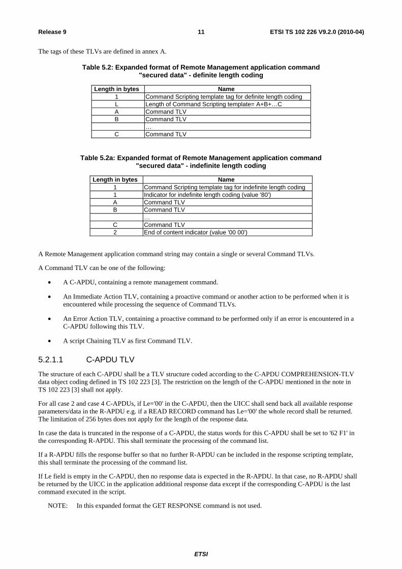
The tags of these TLVs are defined in annex A.
Table 5.2: Expanded format of Remote Management application command "secured data" - definite length coding
Length in bytes Name 1 Command Scripting template tag for definite length coding L Length of Command Scripting template= A+B+…C A Command TLV B Command TLV …
C Command TLV
Table 5.2a: Expanded format of Remote Management application command "secured data" - indefinite length coding
Length in bytes Name 1 Command Scripting template tag for indefinite length coding 1 Indicator for indefinite length coding (value '80') A Command TLV B Command TLV …
C Command TLV 2 End of content indicator (value '00 00')
A Remote Management application command string may contain a single or several Command TLVs.
A Command TLV can be one of the following:
• A C-APDU, containing a remote management command.
• An Immediate Action TLV, containing a proactive command or another action to be performed when it is encountered while processing the sequence of Command TLVs.
• An Error Action TLV, containing a proactive command to be performed only if an error is encountered in a C-APDU following this TLV.
• A script Chaining TLV as first Command TLV.
5.2.1.1 C-APDU TLV
The structure of each C-APDU shall be a TLV structure coded according to the C-APDU COMPREHENSION-TLV data object coding defined in TS 102 223 [3]. The restriction on the length of the C-APDU mentioned in the note in TS 102 223 [3] shall not apply.
For all case 2 and case 4 C-APDUs, if Le='00' in the C-APDU, then the UICC shall send back all available response parameters/data in the R-APDU e.g. if a READ RECORD command has Le='00' the whole record shall be returned. The limitation of 256 bytes does not apply for the length of the response data.
In case the data is truncated in the response of a C-APDU, the status words for this C-APDU shall be set to '62 F1' in the corresponding R-APDU. This shall terminate the processing of the command list.
If a R-APDU fills the response buffer so that no further R-APDU can be included in the response scripting template, this shall terminate the processing of the command list.
If Le field is empty in the C-APDU, then no response data is expected in the R-APDU. In that case, no R-APDU shall be returned by the UICC in the application additional response data except if the corresponding C-APDU is the last command executed in the script.
NOTE: In this expanded format the GET RESPONSE command is not used.
ETSI
ETSI TS 102 226 V9.2.0 (2010-04)12Release 9
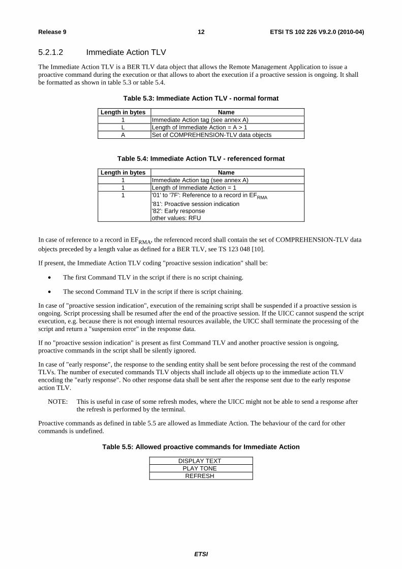
5.2.1.2 Immediate Action TLV
The Immediate Action TLV is a BER TLV data object that allows the Remote Management Application to issue a proactive command during the execution or that allows to abort the execution if a proactive session is ongoing. It shall be formatted as shown in table 5.3 or table 5.4.
Table 5.3: Immediate Action TLV - normal format
Length in bytes Name 1 Immediate Action tag (see annex A) L Length of Immediate Action = A > 1 A Set of COMPREHENSION-TLV data objects
Table 5.4: Immediate Action TLV - referenced format
Length in bytes Name 1 Immediate Action tag (see annex A) 1 Length of Immediate Action = 1 1 '01' to '7F': Reference to a record in EFRMA
'81': Proactive session indication '82': Early response other values: RFU
In case of reference to a record in EFRMA, the referenced record shall contain the set of COMPREHENSION-TLV data
objects preceded by a length value as defined for a BER TLV, see TS 123 048 [10].
If present, the Immediate Action TLV coding "proactive session indication" shall be:
• The first Command TLV in the script if there is no script chaining.
• The second Command TLV in the script if there is script chaining.
In case of "proactive session indication", execution of the remaining script shall be suspended if a proactive session is ongoing. Script processing shall be resumed after the end of the proactive session. If the UICC cannot suspend the script execution, e.g. because there is not enough internal resources available, the UICC shall terminate the processing of the script and return a "suspension error" in the response data.
If no "proactive session indication" is present as first Command TLV and another proactive session is ongoing, proactive commands in the script shall be silently ignored.
In case of "early response", the response to the sending entity shall be sent before processing the rest of the command TLVs. The number of executed commands TLV objects shall include all objects up to the immediate action TLV encoding the "early response". No other response data shall be sent after the response sent due to the early response action TLV.
NOTE: This is useful in case of some refresh modes, where the UICC might not be able to send a response after the refresh is performed by the terminal.
Proactive commands as defined in table 5.5 are allowed as Immediate Action. The behaviour of the card for other commands is undefined.
Table 5.5: Allowed proactive commands for Immediate Action
DISPLAY TEXT PLAY TONE REFRESH
ETSI
ETSI TS 102 226 V9.2.0 (2010-04)13Release 9
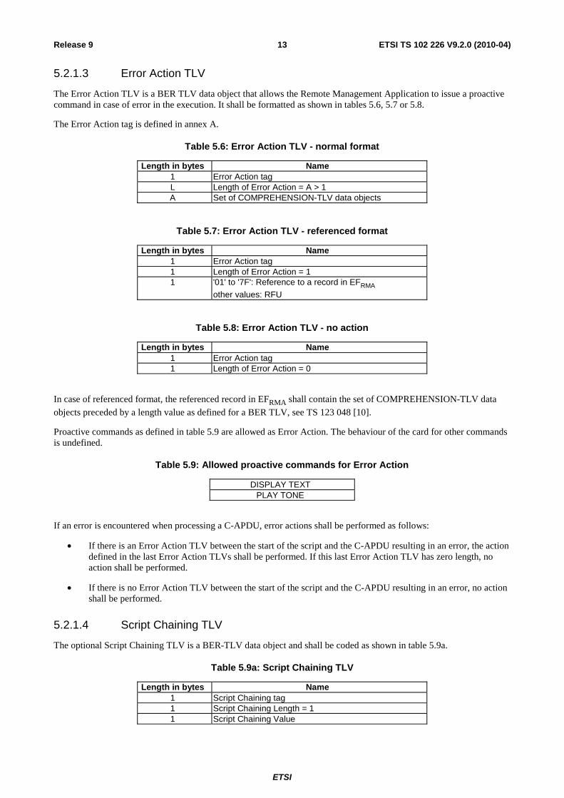
5.2.1.3 Error Action TLV
The Error Action TLV is a BER TLV data object that allows the Remote Management Application to issue a proactive command in case of error in the execution. It shall be formatted as shown in tables 5.6, 5.7 or 5.8.
The Error Action tag is defined in annex A.
Table 5.6: Error Action TLV - normal format
Length in bytes Name 1 Error Action tag L Length of Error Action = A > 1 A Set of COMPREHENSION-TLV data objects
Table 5.7: Error Action TLV - referenced format
Length in bytes Name 1 Error Action tag 1 Length of Error Action = 1 1 '01' to '7F': Reference to a record in EFRMA
other values: RFU
Table 5.8: Error Action TLV - no action
Length in bytes Name 1 Error Action tag 1 Length of Error Action = 0
In case of referenced format, the referenced record in EFRMA shall contain the set of COMPREHENSION-TLV data
objects preceded by a length value as defined for a BER TLV, see TS 123 048 [10].
Proactive commands as defined in table 5.9 are allowed as Error Action. The behaviour of the card for other commands is undefined.
Table 5.9: Allowed proactive commands for Error Action
DISPLAY TEXT PLAY TONE
If an error is encountered when processing a C-APDU, error actions shall be performed as follows:
• If there is an Error Action TLV between the start of the script and the C-APDU resulting in an error, the action defined in the last Error Action TLVs shall be performed. If this last Error Action TLV has zero length, no action shall be performed.
• If there is no Error Action TLV between the start of the script and the C-APDU resulting in an error, no action shall be performed.
5.2.1.4 Script Chaining TLV
The optional Script Chaining TLV is a BER-TLV data object and shall be coded as shown in table 5.9a.
Table 5.9a: Script Chaining TLV
Length in bytes Name 1 Script Chaining tag 1 Script Chaining Length = 1 1 Script Chaining Value

ETSI
ETSI TS 102 226 V9.2.0 (2010-04)14Release 9
The Script Chaining tag is defined in annex A.
If present, the Script Chaining TLV shall be present only once and shall be the first Command TLV in the Command Script. It may only be present for Remote File Management or Remote Application Management. If it is received by any other application standardized in the present document, the error "Script Chaining not supported by this application" shall be sent back to the sending entity.
The Script Chaining Value is defined as follows:
• '01': first script - delete chaining information upon card reset - valid for RFM and RAM.
• '11': first script - keep chaining information across card reset - valid for RFM only.
• '02': subsequent script - subsequent script(s) will follow.
• '03': subsequent script - last script.
Whether or not chaining information is kept across card reset(s) is defined in the first script for the whole chain.
5.2.2 Expanded Remote response structure
The additional response application data which may be sent by a Remote Management application is a BER-TLV data object.
In case no Script Chaining is present in the command list or processing of the Script Chaining produces no error, it shall be formatted according to table 5.10 or table 5.10a.
Two variants exist for the expanded remote response structure:
• The Response Scripting template is a BER-TLV data object as defined in TS 101 220 [5], i.e. it uses definite length coding; see table 5.2. It shall be used if the command scripting template used definite length coding.
• The Response Scripting template is a BER-TLV data object which uses indefinite length coding as defined in ISO/IEC 8825-1 [21]; see table 5.2a. It shall be used if the command scripting template used indefinite length coding.
The tags of these TLVs are defined in annex A.
Table 5.10: Expanded Format of Remote Management application additional response data - definite length coding
Length in bytes Name 1 Response Scripting template tag for definite length coding L Length of Response Scripting template= X+A+B…C X Number of executed Command TLV objects A R-APDU of first executed case 2/ case 4 C-APDU in the script B R-APDU of second executed case 2/ case 4 C-APDU in the script …
C R-APDU of last executed C-APDU (case 1, 2, 3 or 4) in the script or Bad format TLV NOTE: If the last executed C-APDU is a case 2 or case 4 command, its corresponding R-APDU TLV
shall only be present once in the Response Scripting template.
Table 5.10a: Expanded Format of Remote Management application additional response data - indefinite length coding
Length in bytes Name 1 Response Scripting template tag for indefinite length coding 1 Indicator for indefinite length coding (value '80') A R-APDU of first executed C-APDU in the script B R-APDU of second executed C-APDU in the script …
C R-APDU of last executed C-APDU in the script or Bad format TLV 2 End of content indicator (value '00 00')

ETSI
ETSI TS 102 226 V9.2.0 (2010-04)15Release 9
The Number of executed command TLV objects is a BER-TLV data object and shall be coded as shown in table 5.11.
Table 5.11: Number of executed command TLV objects
Length in bytes Description 1 Number of executed command TLV objects tag 1 Length=X X Number of executed command TLV objects
The Number of executed command TLV objects tag is defined in annex A. The Number of executed command TLV objects value corresponds to the number of command TLV objects executed within the command script.
The structure of each R-APDU shall be a TLV structure coded according to the R-APDU COMPREHENSION-TLV data object coding defined in TS 102 223 [3]. The restriction on the length of the R-APDU mentioned in the note in TS 102 223 [3] shall not apply. For Le='00', the length of the R-APDU may be coded on more than two bytes.
A Remote Management application response string may contain a single or several R-APDU TLVs.
In case of an unknown Tag, or TLV with a wrong format (e.g. length > length of BER-TLV or length < 4) is encountered while processing the command script, a Bad format TLV shall be put into the response data and processing of the command script shall be aborted at that point.
The Number of executed C-APDUs shall take into account the incorrectly formatted TLV.
The Bad format TLV is a BER-TLV data object and shall be coded as shown in table 5.12.
Table 5.12: Bad format TLV
Length in bytes Description 1 Bad format TLV tag 1 Length 1 Error type
Error type Coding:
• '01': Unknown Tag found.
• '02': Wrong length found.
• '03': Length not found.
• other values: RFU.
If "proactive session indication" is present in the script and a proactive session is ongoing and the UICC is unable to suspend script processing, the additional response application data shall be formatted according to tables 5.13 or table 5.13a and table 5.14 and indicate "suspension error".
Table 5.13: Expanded Format of Remote Management application additional response data in case of Immediate Action error - definite length coding
Length in bytes Name 1 Response Scripting template tag for definite length coding L Length of Response Scripting template= X+A X Number of executed command TLV objects (value is 1) A Immediate Action Response
ETSI
ETSI TS 102 226 V9.2.0 (2010-04)16Release 9
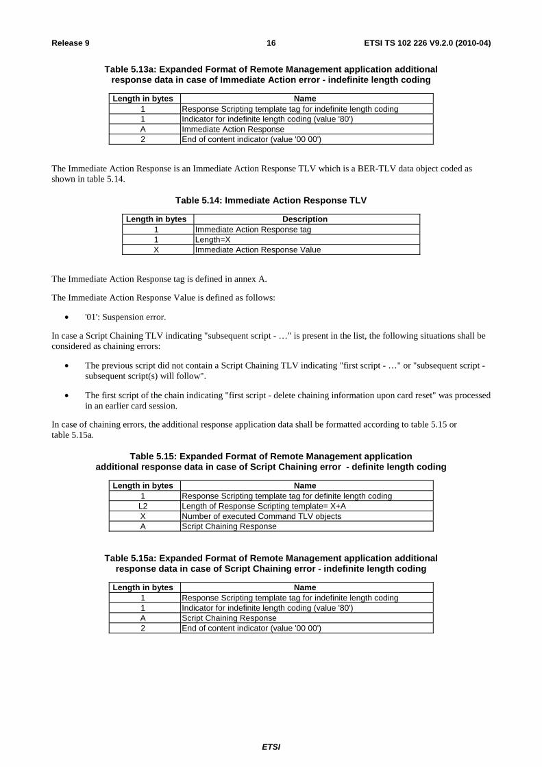
Table 5.13a: Expanded Format of Remote Management application additional response data in case of Immediate Action error - indefinite length coding
Length in bytes Name 1 Response Scripting template tag for indefinite length coding 1 Indicator for indefinite length coding (value '80') A Immediate Action Response 2 End of content indicator (value '00 00')
The Immediate Action Response is an Immediate Action Response TLV which is a BER-TLV data object coded as shown in table 5.14.
Table 5.14: Immediate Action Response TLV
Length in bytes Description 1 Immediate Action Response tag 1 Length=X X Immediate Action Response Value
The Immediate Action Response tag is defined in annex A.
The Immediate Action Response Value is defined as follows:
• '01': Suspension error.
In case a Script Chaining TLV indicating "subsequent script - …" is present in the list, the following situations shall be considered as chaining errors:
• The previous script did not contain a Script Chaining TLV indicating "first script - …" or "subsequent script - subsequent script(s) will follow".
• The first script of the chain indicating "first script - delete chaining information upon card reset" was processed in an earlier card session.
In case of chaining errors, the additional response application data shall be formatted according to table 5.15 or table 5.15a.
Table 5.15: Expanded Format of Remote Management application additional response data in case of Script Chaining error - definite length coding
Length in bytes Name 1 Response Scripting template tag for definite length coding
L2 Length of Response Scripting template= X+A X Number of executed Command TLV objects A Script Chaining Response
Table 5.15a: Expanded Format of Remote Management application additional response data in case of Script Chaining error - indefinite length coding
Length in bytes Name 1 Response Scripting template tag for indefinite length coding 1 Indicator for indefinite length coding (value '80') A Script Chaining Response 2 End of content indicator (value '00 00')
ETSI
ETSI TS 102 226 V9.2.0 (2010-04)17Release 9
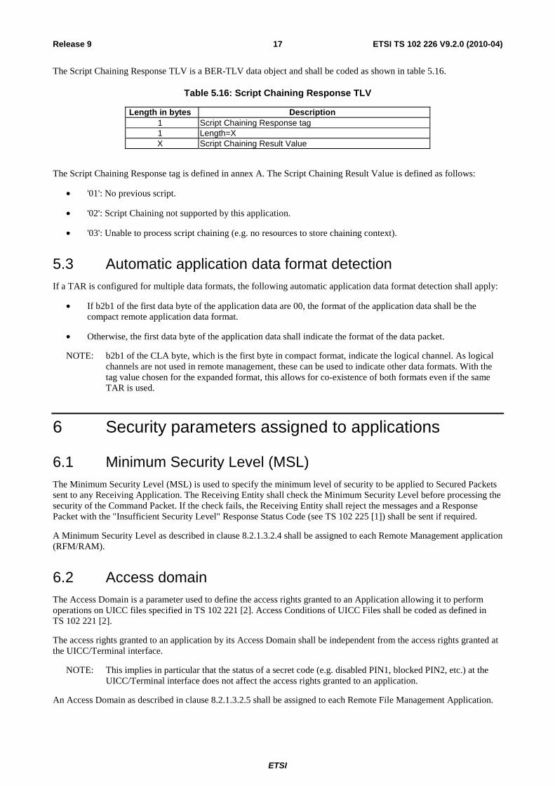
The Script Chaining Response TLV is a BER-TLV data object and shall be coded as shown in table 5.16.
Table 5.16: Script Chaining Response TLV
Length in bytes Description 1 Script Chaining Response tag 1 Length=X X Script Chaining Result Value
The Script Chaining Response tag is defined in annex A. The Script Chaining Result Value is defined as follows:
• '01': No previous script.
• '02': Script Chaining not supported by this application.
• '03': Unable to process script chaining (e.g. no resources to store chaining context).
5.3 Automatic application data format detection If a TAR is configured for multiple data formats, the following automatic application data format detection shall apply:
• If b2b1 of the first data byte of the application data are 00, the format of the application data shall be the compact remote application data format.
• Otherwise, the first data byte of the application data shall indicate the format of the data packet.
NOTE: b2b1 of the CLA byte, which is the first byte in compact format, indicate the logical channel. As logical channels are not used in remote management, these can be used to indicate other data formats. With the tag value chosen for the expanded format, this allows for co-existence of both formats even if the same TAR is used.
6 Security parameters assigned to applications
6.1 Minimum Security Level (MSL) The Minimum Security Level (MSL) is used to specify the minimum level of security to be applied to Secured Packets sent to any Receiving Application. The Receiving Entity shall check the Minimum Security Level before processing the security of the Command Packet. If the check fails, the Receiving Entity shall reject the messages and a Response Packet with the "Insufficient Security Level" Response Status Code (see TS 102 225 [1]) shall be sent if required.
A Minimum Security Level as described in clause 8.2.1.3.2.4 shall be assigned to each Remote Management application (RFM/RAM).
6.2 Access domain The Access Domain is a parameter used to define the access rights granted to an Application allowing it to perform operations on UICC files specified in TS 102 221 [2]. Access Conditions of UICC Files shall be coded as defined in TS 102 221 [2].
The access rights granted to an application by its Access Domain shall be independent from the access rights granted at the UICC/Terminal interface.
NOTE: This implies in particular that the status of a secret code (e.g. disabled PIN1, blocked PIN2, etc.) at the UICC/Terminal interface does not affect the access rights granted to an application.
An Access Domain as described in clause 8.2.1.3.2.5 shall be assigned to each Remote File Management Application.
ETSI
ETSI TS 102 226 V9.2.0 (2010-04)18Release 9
7 Remote File Management (RFM) The concept of embedding APDUs in a command packet and the Additional Response data in a response packet shall be as defined in the previous clauses describing the Compact and expanded Remote Application data format.
Unless a TAR is used that is configured for automatic application data format detection, the Compact and expanded Remote Application data formats shall be distinguished by different TAR values.
For the Expanded Remote Application data format, it is possible to chain two or more scripts using Script Chaining TLVs.
If a Script Chaining TLV indicating "first script - …" or "subsequent script - subsequent script(s) will follow" is processed successfully, the file context (current directory, current file, current tag pointer, etc.) and the PIN verification status at the end of the script shall be remembered until the next script is processed by the Remote File Management application. If the next script received successfully contains a Script Chaining TLV indicating "subsequent script - …", the remembered file context and PIN verification status shall be restored. Else the default context shall be used.
If a non-shareable file is selected by the remembered file context, the mechanisms defined in TS 102 221 [2] limiting the access to non-shareable files shall apply.
NOTE: It is up to the sending entity to guarantee that a sequence of scripts, each relying on the context of the previous one, is processed in the correct sequence by the UICC. This can be achieved by using a reliable transport mechanism, by waiting for a positive response of one script before sending the next, or by using appropriate settings in the security layer ("process only if counter value is one higher than previous value").
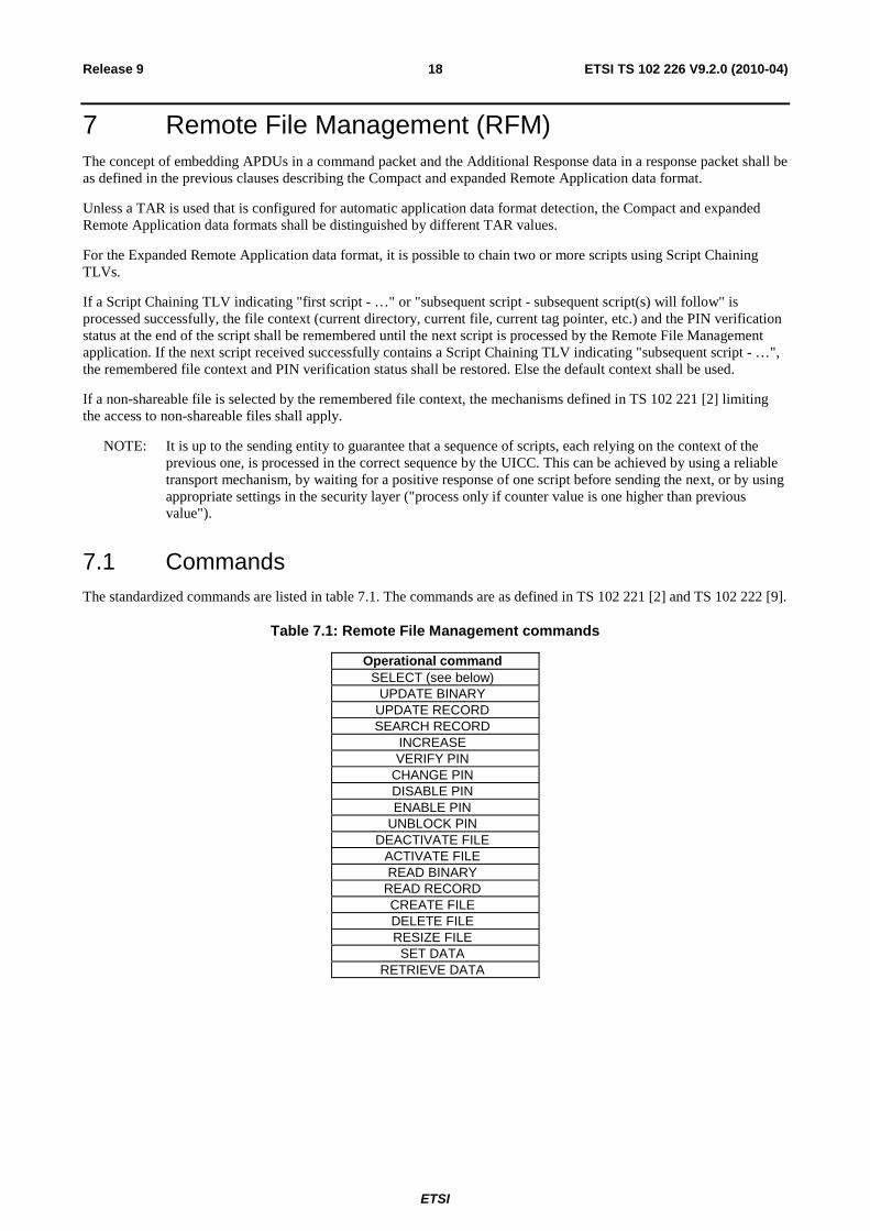
7.1 Commands The standardized commands are listed in table 7.1. The commands are as defined in TS 102 221 [2] and TS 102 222 [9].
Table 7.1: Remote File Management commands
Operational command SELECT (see below)
UPDATE BINARY UPDATE RECORD SEARCH RECORD
INCREASE VERIFY PIN
CHANGE PIN DISABLE PIN ENABLE PIN
UNBLOCK PIN DEACTIVATE FILE
ACTIVATE FILE READ BINARY
READ RECORD CREATE FILE DELETE FILE RESIZE FILE
SET DATA RETRIEVE DATA
ETSI
ETSI TS 102 226 V9.2.0 (2010-04)19Release 9
The SELECT command shall not include the selection by DF name corresponding to P1='04' in the Command Parameters of SELECT (see TS 102 221 [2]).
The Response Data shall be placed in the Additional Response Data element of the Response Packet.
• If P3/Le = '00' in the READ RECORD command, then the UICC shall send back the whole record data.
• If P3/Le = '00' in the READ BINARY command, then the UICC shall send back all data until the end of the file, according to clause 5.1.
• If P3/Le = '00' in the RETRIEVE DATA command, then the UICC shall send back all data until the end of the data object from the current BER-TLV structure EF.
7.2 UICC Shared File System Remote File Management A UICC Shared File System Remote File Management application shall have access only to the MF and all DFs and EFs that are located under the MF.
NOTE: ADFs are not considered to be files located under the MF.
Unless Script Chaining is used, the MF shall be implicitly selected and be the current directory at the beginning of a Command "session".
No ADF shall be accessed by the UICC Shared File System Remote File Management application.
All commands defined in clause 7.1 shall apply.
The TAR value of the UICC Shared File System Remote File Management application is defined in TS 101 220 [5].
7.3 ADF Remote File Management An ADF Remote File Management application shall have access to the DFs and EFs located under the ADF.
Unless Script Chaining is used, the ADF shall be implicitly selected and be the current directory at the beginning of a Command "session".
The UICC Shared File System, i.e. the MF and all DFs and EFs that are located under the MF, may also be accessed, depending on the access rights granted to the ADF Remote File Management application.
NOTE: ADFs are not considered to be files located under the MF.
All commands defined in clause 7.1 shall apply.
The TAR of an ADF RFM application shall be linked to the AID of the application to which the ADF belongs.
The TAR value of an ADF Remote File Management application is defined in TS 101 220 [5].
7.4 RFM implementation over HTTPS When using remote APDUs to perform RFM over HTTPS, the header values defined in TS 102 225 [1] apply. The RFM / HTTP communication flow is illustrated in Annex B.
8 Remote Application Management (RAM) Remote Application Management on a UICC card includes the ability to load, install, and remove applications. This management is under the control of a security domain with card content management capabilities, such as the Issuer Security Domain or any Security Domain with Delegated Management privileges or Authorized Management as described in GlobalPlatform Card Specification [4].

ETSI
ETSI TS 102 226 V9.2.0 (2010-04)20Release 9
All GlobalPlatform features and functionality that are described in the present clause, as well as the assignment of GlobalPlatform privileges shall comply with GlobalPlatform Card Specification [4] as detailed in the UICC Configuration [16].
A RAM Application shall support all features and functionality described in the present clause unless they are specifically described as optional.
The support of the APIs defined in GlobalPlatform Card Specification [4] (Java Card or Multos API) is optional. If implemented, it shall follow the specification in the UICC Configuration [16], especially concerning the Secure Channel Interface usage.
Remote Application Management commands shall be executed according to table "Authorized GlobalPlatform Commands per Card Life Cycle State" of GlobalPlatform Card Specification [4].
The TAR value allocated for the Issuer Security Domain are defined in TS 101 220 [5].
The concept of embedding APDUs in a command packet and the Additional Response data in a response packet shall be as defined in the previous clauses describing the Compact and expanded Remote Application data format.
Unless a TAR is used that is configured for automatic application data format detection, the Compact and expanded Remote Application data formats shall be distinguished by different TAR values.
The Minimum Security Level of a RAM Application shall require at least integrity using CC or DS.
A complying card shall support at least the triple DES algorithm in outer CBC mode for cryptographic computations.
8.1 Remote application management application behaviour Remote Load File loading, Application installation, Load File removal, Application removal, Application locking/unlocking, Application information retrieval shall be compliant to GlobalPlatform Card Specification [4] as detailed in the UICC Configuration [16].
Support of the application personalization described in Global Platform Card Specification [4] is optional.
As a RAM Application is a Receiving Application per clause 4, application selection (SELECT command) and command dispatching as described in GlobalPlatform Card Specification [4] do not apply to Remote Application Management.
8.2 Commands coding and description Commands and responses shall be coded according to GlobalPlatform Card Specification [4] as detailed in the UICC Configuration [16] unless otherwise specified in the present document.
Secure messaging shall be based on TS 102 225 [1]. Except for confidential application management, the secure messaging as defined in GlobalPlatform Card Specification [4] shall not apply to RAM APDU commands and responses (e.g. MAC shall not be present in the command data field). In addition the class byte shall indicate that an APDU command includes no secure messaging.
The logical channel number indicated in the class byte shall be zero.
Command status words placed in the Additional Response Data element of the Response Packet shall be coded according to the GlobalPlatform Card Specification [4] as detailed in the UICC Configuration [16].

ETSI
ETSI TS 102 226 V9.2.0 (2010-04)21Release 9
8.2.1 Commands
The standardized commands are listed in table 8.1.
Table 8.1: Application management commands
Operational command DELETE
SET STATUS INSTALL
LOAD PUT KEY
GET STATUS GET DATA as case 2 command GET DATA as case 4 command
(for Menu parameters) STORE DATA
The Response Data shall be placed in the Additional Response Data element of the Response Packet.
Script chaining may be used for confidential application management as specified in clause 10 or to chain a sequence of STORE DATA commands. It has no effect for other commands. However, whenever it is present for RAM, it shall be processed as defined in this specification.
8.2.1.1 DELETE
The removal of Applications, of Executable Load Files, and of Executable Load Files and its related Applications shall be supported.
The warning status word '6200' (Application has been logically deleted) as defined in Open Platform Card Specification 2.0.1 [7] may be returned.
8.2.1.2 SET STATUS
The management of Applications, Issuer Security Domain and Security Domains Life Cycle States shall be supported.
8.2.1.3 INSTALL
INSTALL [for load], INSTALL [for install] and INSTALL [for make selectable] commands shall be supported.
INSTALL [for personalization] and Install [for extradition] command described in GlobalPlatform Card Specification [4] are optional. A UICC supporting confidential application management as specified in clause X shall support INSTALL [for personalization]. If implemented, both commands shall follow the specification in the UICC Configuration [16].
In addition the support of the combined [for install and make selectable] within the same INSTALL command is mandatory.
8.2.1.3.1 INSTALL [for load]
Support and presence of the Load File Data Block Hash according to GlobalPlatform Card Specification [4] shall be as specified in the UICC Configuration [16].
NOTE: The exact generation of the DAP was not defined in pre-Release 6 predecessors of the present document. Inter-operability with pre-Release 6 implementations should be handled with care.
If present, the Load Parameter Field of the INSTALL [for load] command shall be coded according to GlobalPlatform Card Specification [4].
If the System Specific parameters "Non volatile code space limit" (Tag 'C6'), "Volatile data space limit" (Tag 'C7') and "Non volatile data space limit" (Tag 'C8') are present, the UICC shall be able to handle them.

ETSI
ETSI TS 102 226 V9.2.0 (2010-04)22Release 9
8.2.1.3.2 INSTALL [for install]
If present, the Install Parameter Field of the INSTALL [for install] command shall be coded according to GlobalPlatform Card Specification [4].
If the System Specific parameters "Volatile data space limit" (Tag 'C7') and "Non volatile data space limit" (Tag 'C8') are present, the UICC shall be able to handle them.
The application instance shall be registered with the instance AID present in the INSTALL [for install] command.
In case of JavaCardTM applications, the application may invoke the register(bArray, bOffset, bLength) or the register() method:
• If the register (bArray, bOffset, bLength) is invoked, the AID passed in the parameters shall be the instance AID provided in the install method buffer.
• If the register() method is invoked the instance AID present in the INSTALL [for install] command and the AID within the Load File, as specified in GlobalPlatform Card Specification [4], should be the same.
The "UICC System Specific Parameters" TLV object (Tag 'EA', as defined below) is included in the Install Parameter Field and shall be coded as follows.
Presence Length Name Value Optional 1 Tag of UICC System Specific Parameters constructed field 'EA'
1 Length of UICC System Specific Parameters constructed field 0 to n UICC System Specific Parameters constructed value field.
8.2.1.3.2.1 Coding of the SIM File Access and Toolkit Application Specific Parameters
The "SIM File Access and Toolkit Application Specific Parameters" TLV object (Tag 'CA', as defined below) is included in the "System Specific Parameters" (Tag 'EF') and shall be coded as follows.
Presence Length Name Value Optional 1 Tag of SIM file access and toolkit application specific parameters field 'CA'
1 Length of SIM file access and toolkit application specific parameters field 6 to n SIM file access and toolkit Application specific Parameters
The SIM file access and toolkit application specific parameters field is used to specify the terminal and UICC resources the application instance can use. These resources include the timers, the Bearer Independent protocol channels, menu items for the Set Up Menu, the Minimum Security Level and the TAR Value(s) field. The Network Operator or Service Provider can also define the menu position and the menu identifier of the menus activating the application.
The SIM file access and toolkit parameters are mandatory for applications using the sim.toolkit.ToolkitInterface or sim.access.SIMView interface as defined in TS 143 019 [12]. The Access Domain is applicable to applications using the sim.access.SIMView interface as defined in TS 143 019 [12].
Length Name Value 1 Length of Access Domain field
1 to p Access Domain 1 Priority level of the Toolkit application instance 1 Maximum number of timers allowed for this application instance 1 Maximum text length for a menu entry 1 Maximum number of menu entries allowed for this application
instance = m
1 Position of the first menu entry \ 1 Identifier of the first menu entry ('00' means do not care) | …. | = 2 × m bytes
1 Position of the last menu entry | 1 Identifier of the last menu entry ('00' means do not care) / 1 Maximum number of channels for this application instance 1 Length of Minimum Security Level field
0 to q Minimum Security Level (MSL)

ETSI
ETSI TS 102 226 V9.2.0 (2010-04)23Release 9
Length Name Value 1 Length of TAR Value(s) field
3 × y TAR Value(s) of the Toolkit Application instance
See the following clauses for the description of the parameters fields.
8.2.1.3.2.2 Coding of the UICC System Specific Parameters
If the SIM file access and toolkit parameters TLV object (tag 'CA') is present and the UICC System Specific Parameters TLV object (tag 'EA') is present, the card shall return the Status Word '6A80', incorrect parameters in data field, to the INSTALL [for install] command.
The UICC System Specific Parameters constructed value field of the INSTALL [for Install] command shall be coded as follows:
Presence Length Name Value Optional 1 Tag of UICC Toolkit Application specific parameters field '80' 1 Length of UICC Toolkit Application specific parameters field N UICC Toolkit Application specific parameters Optional 1 Tag of UICC Toolkit parameters DAP 'C3' 1 Length of UICC Toolkit parameters DAP N UICC Toolkit parameters DAP Optional 1 Tag of UICC Access Application specific parameters field '81' 1 Length of UICC Access Application specific parameters field N UICC Access Application specific parameters Optional 1 Tag of UICC Administrative Access Application specific parameters field '82' 1 Length of UICC Administrative Access Application specific parameters field N UICC Administrative Access Application specific parameters
Access parameters for the same ADF may be present in both the UICC Access Application specific parameters field and the UICC Administrative Access Application specific parameters field. The same applies for the UICC file system.
8.2.1.3.2.2.1 UICC Toolkit Application specific parameters field
The UICC toolkit application specific parameters field is used to specify the terminal and UICC resources the application instance can use. These resources include the timers, the Bearer Independent Protocol channels, the services for local bearers, menu items for the Set Up Menu, the Minimum Security Level and the TAR Value(s) field. The Network Operator or Service Provider can also define the menu position and the menu identifier of the menus activating the application.
The UICC toolkit parameters are mandatory for applications using the uicc.toolkit.ToolkitInterface defined in TS 102 241 [6] and for Applets extending the SCWSExtension interface as defined in TS 102 588 [17] that make use of the ProactiveHandler and the ProactiveResponseHandler. None of the toolkit resources will be accessible if the UICC toolkit parameters are missing. These parameters shall be coded as follows:
Length Name Value 1 Priority level of the Toolkit application instance 1 Maximum number of timers allowed for this application instance 1 Maximum text length for a menu entry 1 Maximum number of menu entries allowed for this application
instance = m
1 Position of the first menu entry \ 1 Identifier of the first menu entry ('00' means do not care) | …. | = 2 × m bytes
1 Position of the last menu entry | 1 Identifier of the last menu entry ('00' means do not care) / 1 Maximum number of channels for this application instance 1 Length of Minimum Security Level field
0-q Minimum Security Level (MSL) 1 Length of TAR Value(s) field
3 × y TAR Value(s) of the Toolkit Application instance 1 Maximum number of services for this application instance

ETSI
ETSI TS 102 226 V9.2.0 (2010-04)24Release 9
Any additional parameters shall be ignored by the card.
8.2.1.3.2.2.2 UICC Access Application specific parameters field
The UICC access application specific parameters field is used to specify the access rights. The application instance is granted access rights to files only according to these UICC access parameters.
The UICC access parameters are applicable to applications using the uicc.access.FileView defined in TS 102 241 [6]. These parameters shall be coded as follows:
Presence Name Length
O
Length of UICC file system AID 1 Empty UICC file system AID 0 Length of Access Domain for UICC file system 1 Access Domain for UICC file system n Length of Access Domain DAP 1 Access Domain DAP 0 or n
O
Length of ADF #1 AID 1 ADF #1 AID 5 to 16 Length of Access Domain for ADF #1 1 Access Domain for ADF #1 N Length of Access Domain DAP #1 1 Access Domain DAP #1 0 or n
… … … … … …
O
Length of ADF #n AID 1 ADF #n AID 5 to 16 Length of Access Domain for ADF #n 1 Access Domain for ADF #n n Length of Access Domain DAP #n 1 Access Domain DAP #n 0 or n
See the following clauses for the description of the parameters fields.
8.2.1.3.2.2.3 UICC Toolkit Parameters DAP
The UICC toolkit parameters DAP is an optional signature. The card issuer's security policy may require the presence of this DAP.
The input data used to compute this DAP is the concatenation of the following data:
Description Length Length of instance AID 1 Instance AID 5 to 16 Length of UICC Toolkit parameters 1 UICC Toolkit parameters n
The key used to compute this DAP is: Key identifier '02' of Key Version number '11' in the Issuer Security Domain.
Depending on the key type:
• If padding is required by the algorithm, the data is appended by '80' and filled up with zero or more '00'.
• If DES is used, MAC in CBC mode with initial chaining value set to zero shall be used.
• If AES [13] is used, CMAC mode [15] shall be used. The length of the MAC shall be associated with the key.

ETSI
ETSI TS 102 226 V9.2.0 (2010-04)25Release 9
8.2.1.3.2.2.4 UICC Administrative Access Application specific parameters field
The UICC Administrative access application specific parameters field is used to specify the access rights. The application instance is granted access rights to administrate files only according to these UICC Administrative access parameters.
The UICC Administrative access parameters are applicable to applications using the uicc.access.fileadministration.AdminFileView defined in TS 102 241 [6]. These parameters shall be coded as defined in clause 8.2.1.3.2.2.2.
8.2.1.3.2.3 Description of Toolkit Application Specific Parameters
If the maximum number of timers required is greater than '08' (maximum numbers of timers specified in TS 102 223 [3]), the card shall return the Status Word '6A80', incorrect parameters in data field, to the INSTALL [for install] command.
If the maximum number of channels required is greater than '07' (maximum numbers of channels specified in TS 102 223 [3]), the card shall return the Status Word '6A80', incorrect parameters in data field, to the INSTALL [for install] command.
If the maximum number of services requested is greater than '08' (maximum numbers of services specified in TS 102 223 [3]), the card shall return the Status Word '6A80', incorrect parameters in data field, to the INSTALL [for install] command.
The mechanism to manage the position of the Menu Entries is defined in TS 102 241 [6].
A part of the item identifier shall be under the control of the card system and the other part under the control of the card issuer. Item identifiers are split in two ranges:
• [1...127] under control of the card issuer.
• [128...255] under the control of the toolkit framework.
If the requested item identifier is already allocated, or in the range [128...255], then the card shall reject the INSTALL command. If the requested item identifier is '00', the card shall take the first free value in the range [128...255].
8.2.1.3.2.4 Coding of the Minimum Security Level (MSL)
If the length of the Minimum Security Level (MSL) field is zero, no minimum security level check shall be performed by the Receiving Entity.
If the length of the Minimum Security Level (MSL) field is greater than zero, the Minimum Security Level (MSL) field shall be coded according to the following table.
Length Name 1 MSL Parameter
q to 1 MSL Data
The MSL Data coding and length is defined for each MSL Parameter.
8.2.1.3.2.4.1 MSL Parameter
The possible values for the MSL Parameter are:
Value Name Support MSL Data length '00' RFU RFU N/A '01' Minimum SPI1 Optional 1
'02' to '7F' RFU RFU N/A '80' to 'FE' Reserved for Proprietary Mechanisms Optional N/A
'FF' RFU RFU N/A
ETSI
ETSI TS 102 226 V9.2.0 (2010-04)26Release 9
8.2.1.3.2.4.2 Minimum SPI1
The Minimum Security Level Data (MSLD) for the Minimum SPI1 MSL parameter shall use the same coding as the first octet of the SPI of a command packet (see clause 5.1.1 of TS 102 225 [1]).
The first octet of the SPI field in the incoming message Command Packet (SPI1) shall be checked against the Minimum Security Level Data (MSLD) byte by the receiving entity according to the following rules:
• if SPI1.b2b1 is equal to or greater than MSLD.b2b1;
• if SPI1.b3 is equal to or greater than MSLD.b3; and
• if SPI1.b5b4 is equal to or greater than MSLD.b5b4.
then the Message Security Level is sufficient and the check is successful, otherwise the check is failed.
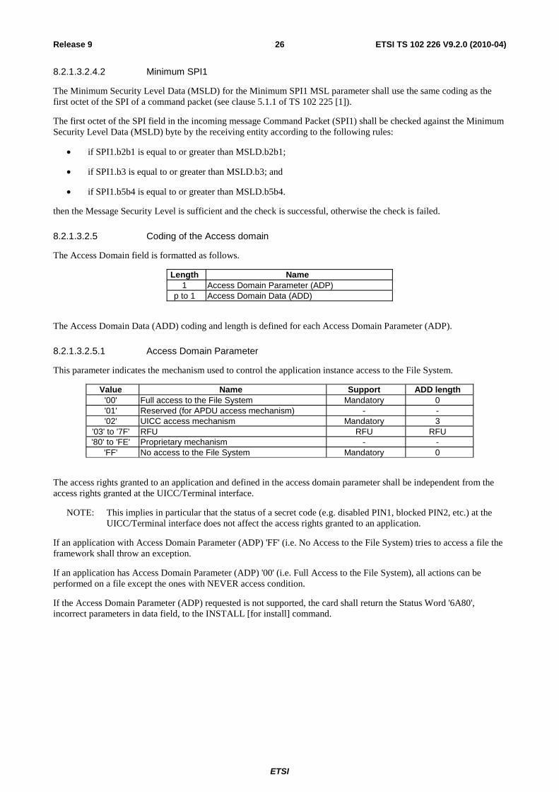
8.2.1.3.2.5 Coding of the Access domain
The Access Domain field is formatted as follows.
Length Name 1 Access Domain Parameter (ADP)
p to 1 Access Domain Data (ADD)
The Access Domain Data (ADD) coding and length is defined for each Access Domain Parameter (ADP).
8.2.1.3.2.5.1 Access Domain Parameter
This parameter indicates the mechanism used to control the application instance access to the File System.
Value Name Support ADD length '00' Full access to the File System Mandatory 0 '01' Reserved (for APDU access mechanism) - - '02' UICC access mechanism Mandatory 3
'03' to '7F' RFU RFU RFU '80' to 'FE' Proprietary mechanism - -
'FF' No access to the File System Mandatory 0
The access rights granted to an application and defined in the access domain parameter shall be independent from the access rights granted at the UICC/Terminal interface.
NOTE: This implies in particular that the status of a secret code (e.g. disabled PIN1, blocked PIN2, etc.) at the UICC/Terminal interface does not affect the access rights granted to an application.
If an application with Access Domain Parameter (ADP) 'FF' (i.e. No Access to the File System) tries to access a file the framework shall throw an exception.
If an application has Access Domain Parameter (ADP) '00' (i.e. Full Access to the File System), all actions can be performed on a file except the ones with NEVER access condition.
If the Access Domain Parameter (ADP) requested is not supported, the card shall return the Status Word '6A80', incorrect parameters in data field, to the INSTALL [for install] command.
ETSI
ETSI TS 102 226 V9.2.0 (2010-04)27Release 9
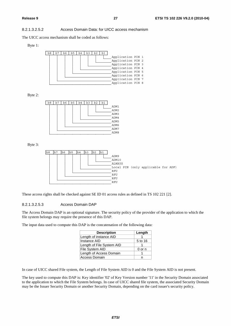
8.2.1.3.2.5.2 Access Domain Data: for UICC access mechanism
The UICC access mechanism shall be coded as follows:
Byte 1:
b8 b7 b6 b5 b4 b3 b2 b1 Application PIN 1 Application PIN 2 Application PIN 3 Application PIN 4 Application PIN 5 Application PIN 6 Application PIN 7 Application PIN 8
Byte 2:
b8 b7 b6 b5 b4 b3 b2 b1 ADM1 ADM2 ADM3 ADM4 ADM5 ADM6 ADM7 ADM8
Byte 3:
b8 b7 b6 b5 b4 b3 b2 b1 ADM9 ADM10 ALWAYS Local PIN (only applicable for ADF) RFU RFU RFU RFU
These access rights shall be checked against SE ID 01 access rules as defined in TS 102 221 [2].
8.2.1.3.2.5.3 Access Domain DAP
The Access Domain DAP is an optional signature. The security policy of the provider of the application to which the file system belongs may require the presence of this DAP.
The input data used to compute this DAP is the concatenation of the following data:
Description Length Length of instance AID 1 Instance AID 5 to 16 Length of File System AID 1 File System AID 0 or n Length of Access Domain 1 Access Domain n
In case of UICC shared File system, the Length of File System AID is 0 and the File System AID is not present.
The key used to compute this DAP is: Key identifier '02' of Key Version number '11' in the Security Domain associated to the application to which the File System belongs. In case of UICC shared file system, the associated Security Domain may be the Issuer Security Domain or another Security Domain, depending on the card issuer's security policy.

ETSI
ETSI TS 102 226 V9.2.0 (2010-04)28Release 9
Depending on the key type:
• If padding is required by the algorithm, the data is appended by '80' and filled up with zero or more '00'.
• If DES is used, MAC in CBC mode with initial value set to zero shall be used.
• If AES [13] is used, CMAC mode [15] shall be used. The length of the MAC shall be associated with the key.
8.2.1.3.2.6 Priority level of the toolkit application
The priority specifies the order of activation of an application compared to the other application registered to, the same event. If two or more applications are registered to the same event and have the same priority level, the applications are activated according to their installation date (i.e. the most recent application is activated first). The following values are defined for priority:
• '00': RFU.
• '01': Highest priority level.
• ...
• 'FF': Lowest priority level.
8.2.1.3.2.7 Coding of TAR Value(s) field
The TAR is defined and coded according to TS 101 220 [5].
It is possible to define several TAR Values at the installation of a Toolkit Application.
The TAR Value(s) field shall be coded according to the following table.
Bytes Description Length 1 to 3 TAR Value 1 3 4 to 6 TAR Value 2 3
… … … 3 × y-2 to 3 × y TAR Value y 3
If the length of TAR Value(s) is zero, the TAR may be taken out of the AID if any.
If the length of the TAR Value(s) is greater than zero then the application instance shall be installed with the TAR Value(s) field defined above and the TAR indicated in the AID if any shall be ignored.
If a TAR Value(s) is already assigned on the card for a Toolkit Application instance or if the length of TAR Value(s) field is incorrect, the card shall return the Status Word '6A80', incorrect parameters in data field, to the INSTALL [for install] command.
8.2.1.3.2.8 Parameters for contactless applications
An application intended to operate in contactless card emulation mode as defined in TS 102 622 [23] shall be installed with Contactless Protocol Parameters and User Interaction Parameters as specified in GlobalPlatform Amendment C [22].
An application intended to operate in contactless reader mode as defined in TS 102 622 [23] shall be installed with parameters given below.
If present, the "Additional Contactless Parameters" TLV object (tag 'B0') shall be included in the "System Specific Parameters" (tag 'EF'). Its value part shall be coded as follows:
Tag Length Value Presence '86' 1 Reader mode protocol data Type A Optional '87' N+2 Reader mode protocol data Type B Optional

ETSI
ETSI TS 102 226 V9.2.0 (2010-04)29Release 9
The presence of the TLVs "Reader mode protocol data Type" indicates the RF technology/technologies that will be active once the Application Availability State of the application as defined in GlobalPlatform Amendment C [22] changes to ACTIVATED.
To present a reader mode application to the user, user interaction parameters as specified in GlobalPlatform Amendment C [22] shall be included in the installation parameters. Applicable parameters for reader mode applications are Application Visibility and Application Family.
8.2.1.3.2.8.1 Reader mode protocol data Type A
The value part of the Reader mode protocol data Type A has the following coding.
Parameter Value Length DATARATE_MAX Maximum data rate supported as defined in TS 102 622 [23] 1
8.2.1.3.2.8.2 Reader mode protocol data Type B
The value part of the Reader mode protocol data Type B has the following coding.
Parameter Value Length AFI Application family identifier as defined in TS 102 622 [23] 1 HIGHER_LAYER_DATA_LENGTH Length of HIGHER_LAYER_DATA 1 HIGHER_LAYER_DATA Higher layer data as defined in TS 102 622 [23] N
8.2.1.4 LOAD
A card supporting DAP verification shall support at least DES scheme for Load File Data Block Signature computation according to GlobalPlatform Card Specification [4].
8.2.1.5 PUT KEY
Key version number and key identifiers of KIc, KID and DEK shall be defined according to TS 102 225 [1].
The key used for ciphering the key values (e.g. KIc, KID or DEK) of the PUT KEY command is the key with identifier 3 (i.e. DEK). It is a static key. If a DES key is used to cipher a key value, the ciphering mode shall be ECB as defined in NIST SP 800-38A [14].
When replacing or adding key(s) within the same key set, or when updating the key version number of a key set, the encrypting key to be used is the DEK of the same key version number as the changed key(s).
When creating keys or key set(s) or when replacing keys that do not belong to a keyset, the encrypting key to be used is the DEK of the same key version number as KIc and KID in the Command Packet containing the PUT KEY command.
The key version number of KIc and KID used to secure the Response Packet shall be the same as the key version number indicated in the Command Packet.
The transport security keys (i.e. KIc/KID) used to secure the Response Packet shall be the same as the ones of the Command Packet containing the PUT KEY command.

ETSI
ETSI TS 102 226 V9.2.0 (2010-04)30Release 9
8.2.1.5.1 PUT KEY for AES
AES is the algorithm defined in [13].
The remote entity shall cipher key values of AES keys only with an AES key of the same or greater length.
The coding of the key type for AES keys shall be '88'.
If an AES key is used to cipher a key value, the following data formatting shall be used:
• The length of the key shall be set to the length of the key data value.
• The key data value shall be constructed as follows:
Description Length Value Presence Length of the key in bytes 1 16, 24 or 32 for AES
16 or 24 for triple DES Mandatory
Ciphered key 16 or 32 Mandatory Length of the MAC in bytes 1 4 or 8 Conditional
• The "length of the MAC" field shall be present if "ciphered key" contains an AES key with key identifier '02' and key version '01' to '0F' or '11'.
• Key ciphering shall use CBC mode as defined in [14] with initial chaining value set to zero.
• Keys that do not fill whole blocks of the AES ciphering scheme (e.g. AES with a key length of 192 bits or triple DES using three different keys) shall be padded to the next block boundary. Padding octets may consist of any plaintext value.
8.2.1.6 GET STATUS
In addition to the mandatory values of the P1 parameter defined in GlobalPlatform Card Specification [4], combinations of the P1 parameter, i.e. setting more than one bit of b5 to b8, may be supported.
The LOGICALLY_DELETED Life Cycle State may be returned as defined in Open Platform Card Specification 2.0.1 [7].
If bit 2 of the P2 parameter is set, the returned GlobalPlatform Registry Data TLV shall include an SCP Registry Data TLV (see table 8.2 for coding) which includes a Menu Parameters TLV for Issuer Security Domain, Security Domains and Applications.
Table 8.2: Format of SCP Registry Data
TAG Length Value 'EA' Variable SCP Registry Data
'80' Variable Menu parameters (see clause 8.2.1.6.1)
8.2.1.6.1 Menu parameters
Table 8.3: Format of Menu parameters
Description Length First menu entry position 1 First menu entry identifier 1 First menu entry state 1 … … Last menu entry position 1 Last menu entry identifier 1 Last menu entry state 1

ETSI
ETSI TS 102 226 V9.2.0 (2010-04)31Release 9
The menu entry identifiers and positions shall be the ones provided in the Menu Entries list defined in TS 102 241 [6], and shall be returned regardless of the menu entry state as well as regardless of the Application life cycle state (e.g. Selectable/Locked, etc.).
The menu entry state is defined as follows:
• '00': menu entry is disabled.
• '01': menu entry is enabled.
• other values: RFU.
8.2.1.7 GET DATA
The value '80' for the CLA byte shall be supported. The value '00' for the CLA byte is optional.
The Issuer Security Domain shall support at least the following data object tags:
• Tag '66': Card Data.
• Tag 'E0': Key Information Template.
• If a UICC contains an Application Provider Security Domain with Delegated Management privilege, the tag values '42' and '45' shall be supported by the ISD as specified in the UICC Configuration [16].
An Application Provider Security Domain shall support at least the following data object tags:
• Tag 'E0': Key Information Template.
The command Get Data is extended to retrieve specific card information with tag values in P1 and P2. The following values have been defined:
• 'FF 1F': Reserved for TS 123 048 [10].
• 'FF 20': Reserved for TS 123 048 [10].
• 'FF 21': Extended Card Resources Tag, this retrieves information on the card resources used and available.
• 'FF 22' to 'FF 3F': reserved for allocation in the present document.
8.2.1.7.1 Void
8.2.1.7.2 Extended Card resources information
After the successful execution of the command, the GET DATA response data field shall be coded as defined in GlobalPlatform [4]. The value of the TLV coded data object referred to in reference control parameters P1 and P2 of the command message is:
Length Description Value 1 Number of installed application tag '81' 1 Number of installed application length X X Number of installed application 1 Free non volatile memory tag '82' 1 Free non volatile memory length Y Y Free non volatile memory 1 Free volatile memory tag '83' 1 Free volatile memory length Z Z Free volatile memory
The free memory indicated shall be at least available for applications to be loaded onto the UICC.

ETSI
ETSI TS 102 226 V9.2.0 (2010-04)32Release 9
8.2.1.8 STORE DATA
A UICC supporting confidential application management as specified in clause 10 shall support the STORE DATA command as specified in the UICC Configuration [16].
Support of the STORE DATA command described in GlobalPlatform Card Specification [4] is optional, but if the Third Party Security Policy requires management of Executable Load Files access constraints, it shall be supported as specified in the following.
The STORE DATA Command is sent to a Security Domain to specify access rights restrictions to its Executable Load Files for a specified Third Party Security Domain.
If the Forbidden Executable Load File List is present in the STORE DATA command, each Executable Load File specified in the list shall be considered as Forbidden for the indicated Third Party Security Domain. Any other Executable Load File not present in the list is allowed for the specified Third Party Security Domain.
Any subsequent loading of Load Files performed by the Third Party Security Domain shall fail if the Load File references one or more Forbidden Executable Load Files. Access rights of Executable Load Files already present on card are not affected by the command.
If a STORE DATA Command is resent to a Security Domain, specifing a Third Party Security Domain for which a Forbidden Executable Load File List has already been defined, the new Forbidden Executable Load File List replaces the previous list for this Third Party Security Domain. If the new Forbidden Executable Load File List is empty the access restrictions for this Third Party Security Domain are removed from the addressed Security Domain.
The UICC shall prevent an Executable Load File from being set as Forbidden for its associated Security Domain.
The STORE DATA command to load Forbidden Load File List shall support the chaining of multiple STORE DATA commands to transfer large amounts of data. Parameter P1 of the command shall indicate non encrypted data and BER-TLV format of the command data field.
TAG 'BE' is used to specify a Forbidden Load File List; the Third Party Security Domain AID TLV object and the Forbidden Load Files AID TLV objects are included in the Store Data Command Message to define the list of Forbidden Load Files for the Third Party Security Domain.
Presence Length Name Value Mandatory 1 Tag of Forbidden Executable Load Files AIDs constructed field 'BE' Mandatory 1 or 2 Length of Forbidden Executable Load Files AIDs constructed field Mandatory Third Party Security Domain AID TLV Optional Forbidden Executable Load File #1 AID TLV Optional Forbidden Executable Load File #2 AID TLV
… … Optional Forbidden Load File #N AID TLV
The Third Party Security Domain AID TLV and the Forbidden Load File AID TLVs are coded as BER-TLV as defined in TS 101 220 [5] using tag '4F'.
8.3 RAM implementation over HTTPS When using remote APDUs to perform RAM over HTTPS, the header values defined in Amendment B of the Global Platform Card Specification v 2.2 [19] apply.

ETSI
ETSI TS 102 226 V9.2.0 (2010-04)33Release 9
9 Additional command for push The PUSH command enables an application to open a BIP channel, to establish a CAT_TP link, to open a TCP connection and/or to send an identification packet on TCP upon a remote entity request.
9.1 Push command behaviour
9.1.1 Request for open channel
The request for open channel allows a remote entity to ask an application on the UICC to open a BIP channel using the OPEN CHANNEL proactive command specified in TS 102 223 [3].
The PUSH command shall be considered completed once the terminal response to the OPEN CHANNEL proactive command has been received by the application.
9.1.2 Request for CAT_TP link establishment
The request for link establishment allows a remote entity to ask an application on the UICC to establish a CAT_TP link as defined in TS 102 127 [11].
The PUSH command shall be considered completed once the link reaches the OPEN state in CAT_TP or the link establishment is terminated due to an error condition.
9.1.3 Behaviour for responses
It is mandatory for applications that process PUSH commands to support additional response data management. The additional response data shall be coded as defined below.
When defining how to send response packets, it shall be taken into account that the processing of the PUSH command will result in proactive commands being issued.
9.1.4 Request for TCP connection
The request for a TCP connection allows a remote entity to ask an application on the UICC to establish a TCP connection as defined in TS 102 483 [20].
9.1.5 Request for Identification Packet
The request for an identification packet allows a remote entity to ask an application on the UICC to send a data packet containing identification information on a TCP connection.
9.2 Commands coding Each command is coded as an APDU. This table extends the command tables defined in clauses 7 and 8 for applications supporting BIP and/or CAT_TP.
Table 9.1: Commands
Operational command PUSH

ETSI
ETSI TS 102 226 V9.2.0 (2010-04)34Release 9
The PUSH command shall be coded as follows:
Code Value CLA '80' INS 'EC' P1 '01'
'80' reserved for application specific usage P2 '01': Request for BIP channel opening
'02': Request for CAT_TP link establishment '03': Request for TCP connection '04': Request for Identification Packet (see note)
Lc Length of subsequent data field Data Described below
NOTE: These values only apply for P1 = '01'.
9.2.1 Data for BIP channel opening
Command data:
Any COMPREHENSION-TLV data objects as defined for OPEN CHANNEL in TS 102 223 [3] can be present in the data field of the PUSH command. In addition, the application may define default values for one or more of these data objects. The application shall use the data objects provided by both means to construct the OPEN CHANNEL command, whereby the objects provided in the PUSH command take precedence.
For OPEN CHANNEL, related to packet data service bearer, in TS 102 223 [3] the following rules shall apply:
• The "Other address (local address)" parameter shall not be included in the command.
• "Login" parameter and "Password" parameter shall be both present or absent in the command.
If these rules are not satisfied the Push requesting BIP open channel is rejected with status word set to '6A 80'.
Response parameters/data:
If the OPEN CHANNEL command was successful (general result < '10'), the status word of the PUSH command shall be set to '90 00'.
If the OPEN CHANNEL command fails (general result ≥ '10'), the status word of the PUSH command shall be set to '6F 00' and the Result TLV of the TERMINAL RESPONSE shall be used as response data in the additional response data.
9.2.2 Data for CAT_TP link establishment
Command data:
Description Format from TS 102 223 [3] M/O/C CAT_TP Destination Port UICC/terminal interface transport level M Max SDU size Buffer size O Identification data Channel data O
For CAT_TP Destination Port the transport protocol type is insignificant and shall be set to zero. For the PUSH command, an allocable port number shall be used.
If the Max SDU size data object is present in the command data field of the PUSH command and is non null data object, and if the size is available on the UICC, then the UICC shall use the requested size.
If the Max SDU size data object is not present in the command data field of the PUSH command or is null data object, or if the UICC is not able to provide the requested size, then the UICC shall use another appropriate value.
NOTE: Max PDU length is already defined in the OPEN CHANNEL proactive command and the TERMINAL RESPONSE to it.
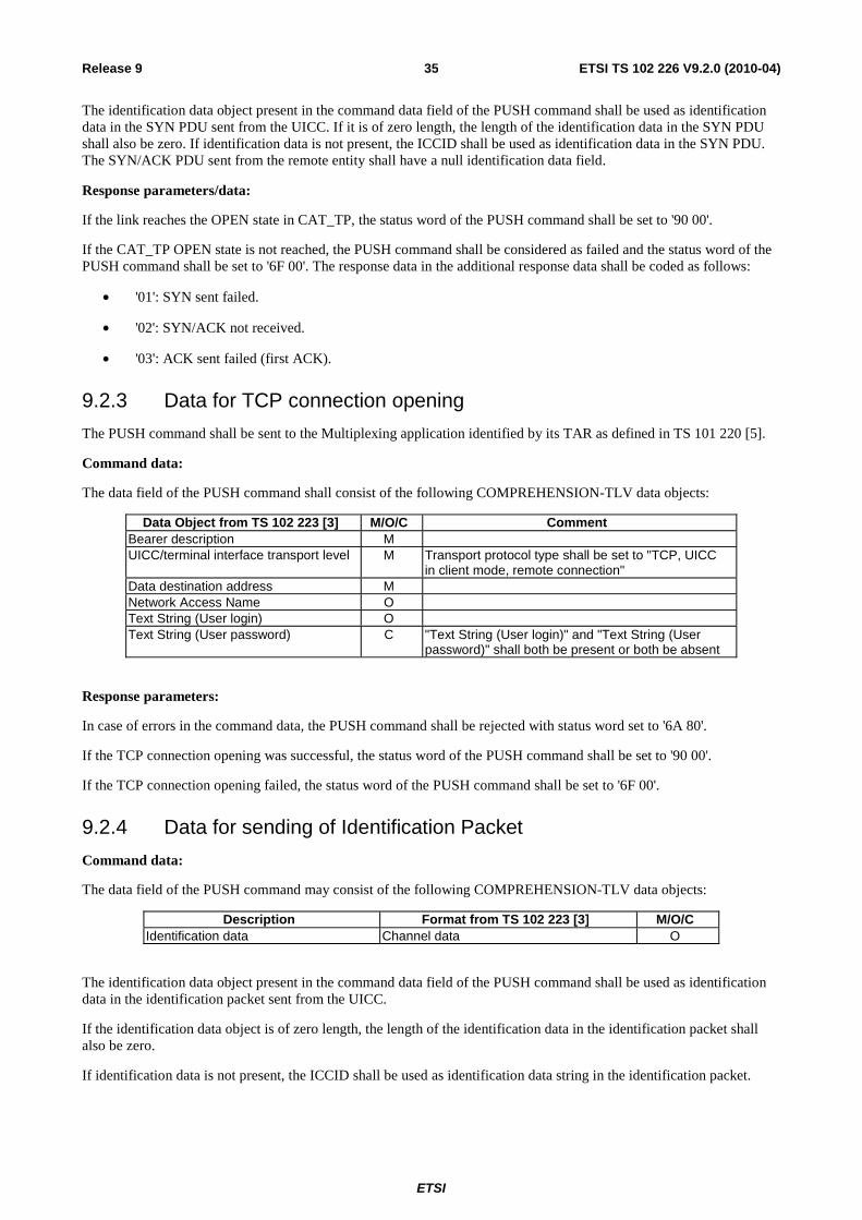
ETSI
ETSI TS 102 226 V9.2.0 (2010-04)35Release 9
The identification data object present in the command data field of the PUSH command shall be used as identification data in the SYN PDU sent from the UICC. If it is of zero length, the length of the identification data in the SYN PDU shall also be zero. If identification data is not present, the ICCID shall be used as identification data in the SYN PDU. The SYN/ACK PDU sent from the remote entity shall have a null identification data field.
Response parameters/data:
If the link reaches the OPEN state in CAT_TP, the status word of the PUSH command shall be set to '90 00'.
If the CAT_TP OPEN state is not reached, the PUSH command shall be considered as failed and the status word of the PUSH command shall be set to '6F 00'. The response data in the additional response data shall be coded as follows:
• '01': SYN sent failed.
• '02': SYN/ACK not received.
• '03': ACK sent failed (first ACK).
9.2.3 Data for TCP connection opening
The PUSH command shall be sent to the Multiplexing application identified by its TAR as defined in TS 101 220 [5].
Command data:
The data field of the PUSH command shall consist of the following COMPREHENSION-TLV data objects:
Data Object from TS 102 223 [3] M/O/C Comment Bearer description M UICC/terminal interface transport level M Transport protocol type shall be set to "TCP, UICC
in client mode, remote connection" Data destination address M Network Access Name O Text String (User login) O Text String (User password) C "Text String (User login)" and "Text String (User
password)" shall both be present or both be absent
Response parameters:
In case of errors in the command data, the PUSH command shall be rejected with status word set to '6A 80'.
If the TCP connection opening was successful, the status word of the PUSH command shall be set to '90 00'.
If the TCP connection opening failed, the status word of the PUSH command shall be set to '6F 00'.
9.2.4 Data for sending of Identification Packet
Command data:
The data field of the PUSH command may consist of the following COMPREHENSION-TLV data objects:
Description Format from TS 102 223 [3] M/O/C Identification data Channel data O
The identification data object present in the command data field of the PUSH command shall be used as identification data in the identification packet sent from the UICC.
If the identification data object is of zero length, the length of the identification data in the identification packet shall also be zero.
If identification data is not present, the ICCID shall be used as identification data string in the identification packet.

ETSI
ETSI TS 102 226 V9.2.0 (2010-04)36Release 9
Response parameters:
If the identification packet was sent successfully, the status word of the PUSH command shall be set to '90 00'.
If sending of the identification packet failed, the status word of the PUSH command shall be set to '6F 00'.
9.3 Closing of the BIP channel The BIP channel shall be closed using the CLOSE CHANNEL proactive command specified in TS 102 223 [3] once the only or last link using the channel has been closed.
10 Confidential application management The features in this clause are defining confidential application management, which enables application providers to securely manage their applications on the UICC through the network of the card owner while keeping confidentiality.
Dependent on the scenario, confidential application management requires additional Security Domains:
• APSDs (Application Provider Security Domains) that provide cryptographic services for applications of the AP;
• APSDs that provide OTA capabilities;
• APSDs that provide GlobalPlatform secure channel capabilities without having OTA capabilities themselves;
• APSDs that are separated from the ISD; and
• combinations of the above;
• a CASD (Controlling Authority Security Domain), which provides security services for confidential setup of security domains.
The following feature is required for the APSDs:
• The ability to personalise its applications.
Dependent on the use case, APSDs can be configured in different hierarchies as specified in GlobalPlatform Card Specification [4] and the UICC Configuration [16].
The following clauses specify different features for confidential application management that may be supported by APSDs and the CASD.
The instantiation and the personalisation of a Security Domain are defined in the UICC Configuration [16].
10.1 Confidential loading If confidential loading of applications is supported, it shall be implemented as specified in the UICC Configuration [16] for the LOAD command using tag 'D4' for encrypted load files, for the key used for deciphering the load file, and for the Ciphered Load File Data Block privilege.

ETSI
ETSI TS 102 226 V9.2.0 (2010-04)37Release 9
10.2 Additional application provider security If an application provider wants to communicate confidentially with his security domain or an application in this security domain, and his security domain has no OTA capability, encapsulation of secured APDUs in secured packets shall be implemented as follows:
• The command string shall use the Expanded Remote Application data format.
• The command string shall be secured using SCP02 with implementation option "i" = '55' according to GlobalPlatform Card Specification [4], i.e. the APDUs to be protected shall be included in a GlobalPlatform secure channel session starting with INITIALIZE UPDATE and EXTERNAL AUTHENTICATE, using the GlobalPlatform secure channel keys of a security domain that has no OTA capabilities.
• If a script does not contain chaining information, the SCP02 secure channel session shall be terminated at the end of the command string.
• If a script contains the chaining information "first script" or "subsequent script(s) will follow", the SCP02 secure channel session shall continue with the next script until the last script, unless one of the following conditions, which shall terminate the secure channel session, applies:
- a new first script or a script without chaining information is received but no last script of the previous secure channel session has been received;
- card reset.
• The TAR of the command string shall represent the security domain that processes the SCP02 security or an application associated to this security domain. In the latter case, the GlobalPlatform API for the secure channel services, which is specified in GlobalPlatform Card Specification [4], shall be available for the application.
• The security domain that processes the SCP02 security shall be part of a hierarchy of security domains, where at least one ancestor has OTA capabilities.
• The command string shall be contained in a secure packet that is unwrapped by the closest ascendant security domain with OTA capabilities as specified in UICC Configuration [16].
The support of the API described in Card Specification Version 2.2, Amendment A [18] is optional.
10.3 Confidential setup of security domains If confidential setup of security domains is supported, it shall be implemented as follows:
• Scenario #2.B (Push Model) as specified in the UICC Configuration [16] shall be supported.
• Scenario #1 (Pull Model) as specified in the UICC Configuration [16] may be supported.
NOTE: An additional Scenario for the Pull Model is FFS.
10.4 Application personalisation in an APSD The mechanism specified in the UICC Configuration [16] to personalize their associated applications, using INSTALL [for personalization] and STORE DATA, shall be supported by all security domains.
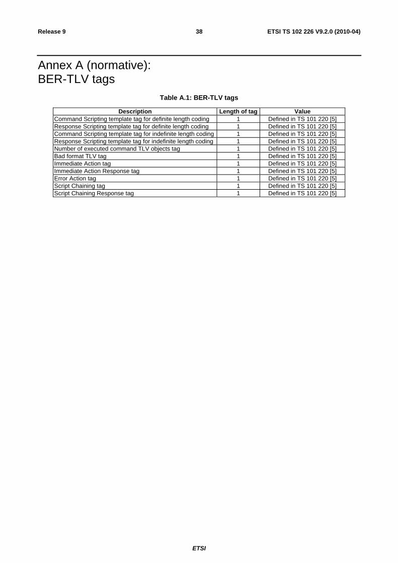
ETSI
ETSI TS 102 226 V9.2.0 (2010-04)38Release 9
Annex A (normative): BER-TLV tags
Table A.1: BER-TLV tags
Description Length of tag Value Command Scripting template tag for definite length coding 1 Defined in TS 101 220 [5] Response Scripting template tag for definite length coding 1 Defined in TS 101 220 [5] Command Scripting template tag for indefinite length coding 1 Defined in TS 101 220 [5] Response Scripting template tag for indefinite length coding 1 Defined in TS 101 220 [5] Number of executed command TLV objects tag 1 Defined in TS 101 220 [5] Bad format TLV tag 1 Defined in TS 101 220 [5] Immediate Action tag 1 Defined in TS 101 220 [5] Immediate Action Response tag 1 Defined in TS 101 220 [5] Error Action tag 1 Defined in TS 101 220 [5] Script Chaining tag 1 Defined in TS 101 220 [5] Script Chaining Response tag 1 Defined in TS 101 220 [5]

ETSI
ETSI TS 102 226 V9.2.0 (2010-04)39Release 9
Annex B (informative): RFM over HTTP Communication Flow The following diagram illustrates an RFM process communication flow over a TLS connection (established over a BIP TCP connection as specified in TS 102 223 [3] or a direct IP connection as specified in TS 102 483 [20]). The TCP connection opening is typically triggered by a triggering message following the format specified in Amendment B of the Global Platform Card Specification v 2.2 [19].

ETSI
ETSI TS 102 226 V9.2.0 (2010-04)40Release 9
Figure B.1
TLS Handshake
Open TCP Connectio
n
String with APDU(s) response
POST <uri> HTTP/1.1
X-Admin-Protocol:
globalplatform-remote-admin/1.0
Content-Type:
application/vnd.etsi.scp.response-data;version=1.0
[response string]
String with APDU(s)
HTTP/1.1 200 OK
X-Admin-Protocol:
globalplatform-remote-admin/1.0
Content-Type:
application/vnd.etsi.scp.command-data;version=1.0
X-Admin-Targeted-Application:
RFM Application-AID
[command string]
POST <uri> HTTP/1.1
X-Admin-Protocol:
globalplaform-remote-admin/1.0
RFM's SD
Process APDU (1)
Remote Administration
Server
Request connection
Use OTASD keys for TLS security
Process APDU (i)
Process APDU (n)
RFM Application
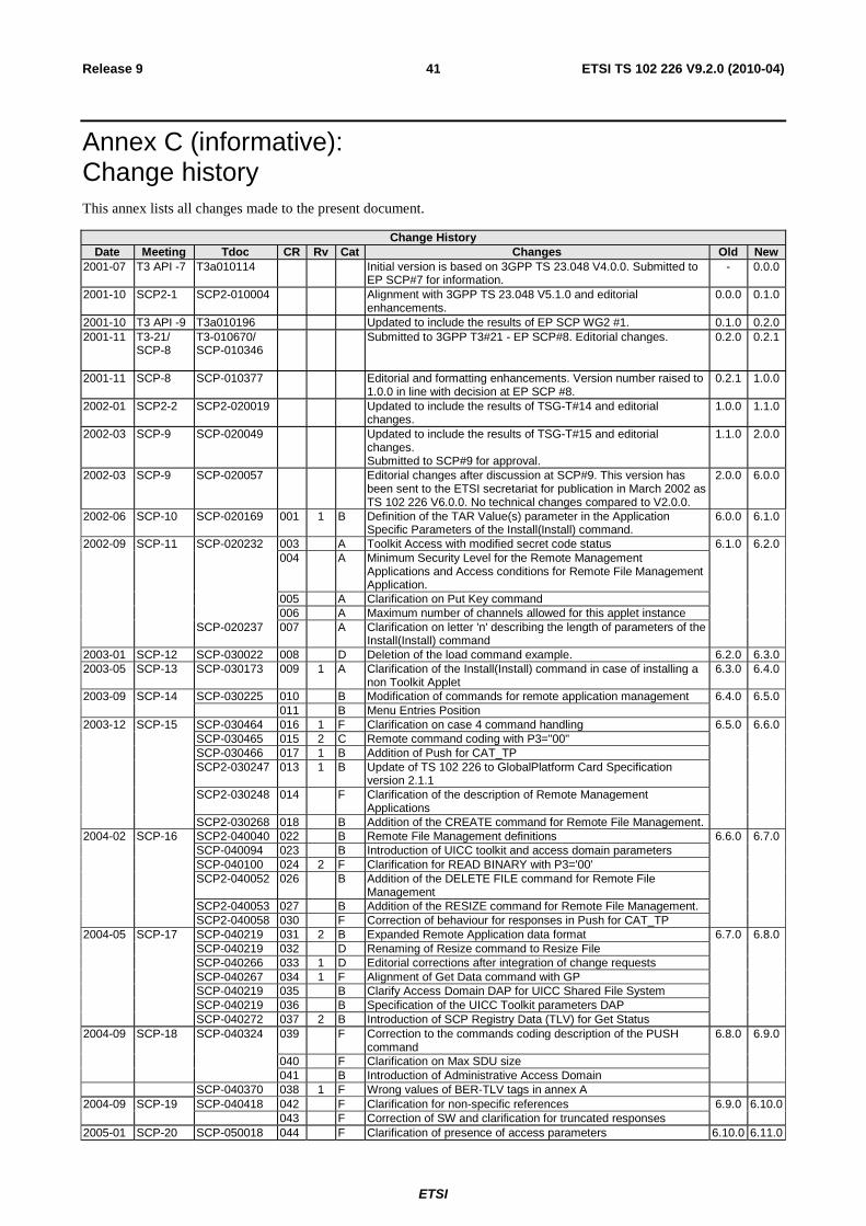
ETSI
ETSI TS 102 226 V9.2.0 (2010-04)41Release 9
Annex C (informative): Change history This annex lists all changes made to the present document.
Change History Date Meeting Tdoc CR Rv Cat Changes Old New
2001-07 T3 API -7 T3a010114 Initial version is based on 3GPP TS 23.048 V4.0.0. Submitted to EP SCP#7 for information.
- 0.0.0
2001-10 SCP2-1 SCP2-010004 Alignment with 3GPP TS 23.048 V5.1.0 and editorial enhancements.
0.0.0 0.1.0
2001-10 T3 API -9 T3a010196 Updated to include the results of EP SCP WG2 #1. 0.1.0 0.2.0 2001-11 T3-21/
SCP-8
T3-010670/ SCP-010346
Submitted to 3GPP T3#21 - EP SCP#8. Editorial changes. 0.2.0 0.2.1
2001-11 SCP-8 SCP-010377 Editorial and formatting enhancements. Version number raised to 1.0.0 in line with decision at EP SCP #8.
0.2.1 1.0.0
2002-01 SCP2-2 SCP2-020019 Updated to include the results of TSG-T#14 and editorial changes.
1.0.0 1.1.0
2002-03 SCP-9 SCP-020049 Updated to include the results of TSG-T#15 and editorial changes. Submitted to SCP#9 for approval.
1.1.0 2.0.0
2002-03 SCP-9 SCP-020057 Editorial changes after discussion at SCP#9. This version has been sent to the ETSI secretariat for publication in March 2002 as TS 102 226 V6.0.0. No technical changes compared to V2.0.0.
2.0.0 6.0.0
2002-06 SCP-10 SCP-020169 001 1 B Definition of the TAR Value(s) parameter in the Application Specific Parameters of the Install(Install) command.
6.0.0 6.1.0
2002-09 SCP-11 SCP-020232 003 A Toolkit Access with modified secret code status 6.1.0 6.2.0 004 A Minimum Security Level for the Remote Management
Applications and Access conditions for Remote File Management Application.
005 A Clarification on Put Key command 006 A Maximum number of channels allowed for this applet instance SCP-020237 007 A Clarification on letter 'n' describing the length of parameters of the
Install(Install) command
2003-01 SCP-12 SCP-030022 008 D Deletion of the load command example. 6.2.0 6.3.0 2003-05 SCP-13 SCP-030173 009 1 A Clarification of the Install(Install) command in case of installing a
non Toolkit Applet 6.3.0 6.4.0
2003-09 SCP-14 SCP-030225 010 B Modification of commands for remote application management 6.4.0 6.5.0 011 B Menu Entries Position 2003-12 SCP-15 SCP-030464 016 1 F Clarification on case 4 command handling 6.5.0 6.6.0 SCP-030465 015 2 C Remote command coding with P3="00" SCP-030466 017 1 B Addition of Push for CAT_TP SCP2-030247 013 1 B Update of TS 102 226 to GlobalPlatform Card Specification
version 2.1.1
SCP2-030248 014 F Clarification of the description of Remote Management Applications
SCP2-030268 018 B Addition of the CREATE command for Remote File Management. 2004-02 SCP-16 SCP2-040040 022 B Remote File Management definitions 6.6.0 6.7.0 SCP-040094 023 B Introduction of UICC toolkit and access domain parameters SCP-040100 024 2 F Clarification for READ BINARY with P3='00' SCP2-040052 026 B Addition of the DELETE FILE command for Remote File
Management
SCP2-040053 027 B Addition of the RESIZE command for Remote File Management. SCP2-040058 030 F Correction of behaviour for responses in Push for CAT_TP 2004-05 SCP-17 SCP-040219 031 2 B Expanded Remote Application data format 6.7.0 6.8.0 SCP-040219 032 D Renaming of Resize command to Resize File SCP-040266 033 1 D Editorial corrections after integration of change requests SCP-040267 034 1 F Alignment of Get Data command with GP SCP-040219 035 B Clarify Access Domain DAP for UICC Shared File System SCP-040219 036 B Specification of the UICC Toolkit parameters DAP SCP-040272 037 2 B Introduction of SCP Registry Data (TLV) for Get Status 2004-09 SCP-18 SCP-040324 039 F Correction to the commands coding description of the PUSH
command 6.8.0 6.9.0
040 F Clarification on Max SDU size 041 B Introduction of Administrative Access Domain SCP-040370 038 1 F Wrong values of BER-TLV tags in annex A 2004-09 SCP-19 SCP-040418 042 F Clarification for non-specific references 6.9.0 6.10.0 043 F Correction of SW and clarification for truncated responses 2005-01 SCP-20 SCP-050018 044 F Clarification of presence of access parameters 6.10.0 6.11.0

ETSI
ETSI TS 102 226 V9.2.0 (2010-04)42Release 9
Change History Date Meeting Tdoc CR Rv Cat Changes Old New
2005-09 SCP-22 SCP-050243 045 F Correction to status words sent back in the Remote Management Application response data in case data is truncated
6.11.0 6.12.0
046 F Clarification of data sent in compact remote response 2006-05 SCP-25 SCP-060132 048 B Mandatory support of responses to push commands 6.12.0 7.0.0 2006-07 SCP-26 SCP-060257 048 A Clarification of the presence of the last R-APDU 7.0.0 7.1.0
049 1 D Correction of abbreviation SCP-060280 050 1 B Reservation of an application specific P1 value in the PUSH
command 2006-09 SCP-27 SCP-060471 051 1 A Correction of the release for references 7.1.0 7.2.0
SCP-060472 054 1 B Add new response TLV in case of a bad formatted C-APDU. 2007-01 SCP-29 SCP-070053 055 B Action TLVs in Command Scripting Template 7.2.0 7.3.0 2007-05 SCP-30 SCP-070137 058 F Clarification on BIP Open Channel parameters in Push command 7.3.0 7.4.0 2007-08 SCP-32 SCP-070317 060 A Correction of the coding of the SCP Registry Data 7.4.0 7.5.0 2008-09 SCP-32 SCP-070317 060 A Correction of the coding of the SCP Registry Data
(reimplemented) 7.5.0 7.5.1
2008-11 SCP-33 SCP-070442 053 4 B Remote Management with Script chaining 7.5.1 7.6.0 2008-11 SCP-39 SCP-080428 061 B Addition of AES to PUT KEY command 7.6.0 8.0.0 2008-11 SCP-39 SCP-080428 062 B Automatic application data format detection 7.6.0 8.0.0 2009-01 SCP-40 SCP-090053 063 C Update to GlobalPlatform Card Specification v2.2 8.0.0 8.1.0 2009-01 SCP-40 SCP-090024 064 B Creation and replacement of DAP key 8.0.0 8.1.0 2009-01 SCP-40 SCP-090024 067 F Clarification of encryption mode for key values 8.0.0 8.1.0 2009-05 SCP-41 SCP-090117 068 B Modification of Install(Install) for Applets registered to the SCWS
using Toolkit resources 8.1.0 8.2.0
2009-05 SCP-41 SCP-090117 070 A Correction of script chaining 8.1.0 8.2.0 2009-05 SCP-41 SCP-090117 071 2 B Support of Confidential Card Content Management 8.2.0 9.0.0 2009-07 SCP-42 SCP-090228 072 B Clarification of confidential application management 9.0.0 9.1.0 2009-10 SCP-43 SCP-090326 074 B Remote Management over HTTPS 9.1.0 9.2.0 2009-10 SCP-43 SCP-090326 075 B Indefinite length coding for remote command and response
structures 9.1.0 9.2.0
2009-10 SCP-43 SCP-090326 073 B Script chaining for RAM 9.1.0 9.2.0 2009-10 SCP-43 SCP-090326 076 B Addition of push mechanism for TCP 9.1.0 9.2.0 2009-10 SCP-43 SCP-090326 077 B Support of Constrained Load File list in the STORE DATA
Command 9.1.0 9.2.0
2009-10 SCP-43 SCP-090326 078 B Addition of confidential setup of security domains 9.1.0 9.2.0 2010-03 SCP-44 SCP(10)0085 077 1 B Support of Constrained Load File list in the STORE DATA
Command (with corrections) 9.1.0 9.2.0
2010-03 SCP-44 SCP(10)0034 080 B Addition of install parameters for contactless applications 9.1.0 9.2.0

ETSI
ETSI TS 102 226 V9.2.0 (2010-04)43Release 9
History
Document history
V9.0.0 June 2009 Publication
V9.1.0 October 2009 Publication
V9.2.0 April 2010 Publication