TS 101 545-3 - V1.1.1 - Digital Video Broadcasting (DVB - ETSI
131
ETSI TS 101 545-3 V1.1.1 (2012-05) Digital Video Broadcasting (DVB); Second Generation DVB Interactive Satellite System (DVB-RCS2); Part 3: Higher Layers Satellite Specification Technical Specification
Transcript of TS 101 545-3 - V1.1.1 - Digital Video Broadcasting (DVB - ETSI

ETSI TS 101 545-3 V1.1.1 (2012-05)
Digital Video Broadcasting (DVB); Second Generation DVB Interactive Satellite System (DVB-RCS2);
Part 3: Higher Layers Satellite Specification
Technical Specification

ETSI
ETSI TS 101 545-3 V1.1.1 (2012-05)2
Reference DTS/JTC-DVB-295-3
Keywords DVB, interaction, satellite
ETSI
650 Route des Lucioles F-06921 Sophia Antipolis Cedex - FRANCE
Tel.: +33 4 92 94 42 00 Fax: +33 4 93 65 47 16
Siret N° 348 623 562 00017 - NAF 742 C
Association à but non lucratif enregistrée à la Sous-Préfecture de Grasse (06) N° 7803/88
Important notice
Individual copies of the present document can be downloaded from: http://www.etsi.org
The present document may be made available in more than one electronic version or in print. In any case of existing or perceived difference in contents between such versions, the reference version is the Portable Document Format (PDF).
In case of dispute, the reference shall be the printing on ETSI printers of the PDF version kept on a specific network drive within ETSI Secretariat.
Users of the present document should be aware that the document may be subject to revision or change of status. Information on the current status of this and other ETSI documents is available at
http://portal.etsi.org/tb/status/status.asp
If you find errors in the present document, please send your comment to one of the following services: http://portal.etsi.org/chaircor/ETSI_support.asp
Copyright Notification
No part may be reproduced except as authorized by written permission. The copyright and the foregoing restriction extend to reproduction in all media.
© European Telecommunications Standards Institute 2012.
© European Broadcasting Union 2012. All rights reserved.
DECTTM, PLUGTESTSTM, UMTSTM and the ETSI logo are Trade Marks of ETSI registered for the benefit of its Members.
3GPPTM and LTE™ are Trade Marks of ETSI registered for the benefit of its Members and of the 3GPP Organizational Partners.
GSM® and the GSM logo are Trade Marks registered and owned by the GSM Association.
ETSI
ETSI TS 101 545-3 V1.1.1 (2012-05)3
Contents
Intellectual Property Rights ................................................................................................................................ 6
Foreword ............................................................................................................................................................. 6
Introduction ........................................................................................................................................................ 6
1 Scope ........................................................................................................................................................ 8
2 References ................................................................................................................................................ 8
2.1 Normative references ......................................................................................................................................... 8
2.2 Informative references ........................................................................................................................................ 9
3 Definitions, symbols and abbreviations ................................................................................................. 14
3.1 Definitions ........................................................................................................................................................ 14
3.2 Symbols ............................................................................................................................................................ 18
3.3 Abbreviations ................................................................................................................................................... 18
4 Reference System Architecture .............................................................................................................. 22
4.1 System Roles .................................................................................................................................................... 23
4.2 Higher Layer functional modules ..................................................................................................................... 24
4.3 Reference Architecture for Higher Layers ....................................................................................................... 25
5 Operator Virtual Networks (OVN), SVNs and VRFs ............................................................................ 26
6 Satellite Virtual Network (SVN) addressing .......................................................................................... 27
6.1 SVN-MAC identifier ........................................................................................................................................ 27
6.2 IP unicast address resolution to SVN-MAC ..................................................................................................... 27
6.2.1 IPv4 address resolution for M and C SVN-MAC ....................................................................................... 28
6.2.2 Network address resolution to user traffic SVN-MAC ............................................................................... 28
6.2.3 Multicast address resolution to a multicast SVN-MAC .............................................................................. 28
7 Network Layer Functions ....................................................................................................................... 29
7.1 Network Interfaces and Forwarding ................................................................................................................. 29
7.2 IPv4/IPv6 Interface to the link layer................................................................................................................. 31
7.2.1 IPv4 Interface to the Link Layer ................................................................................................................. 31
7.2.2 IPv6 Interface to the Link Layer ................................................................................................................. 31
7.2.3 Network Address Translation (NAT / NAPT) (optional) ........................................................................... 31
7.3 RCST Routing function .................................................................................................................................... 32
7.3.1 Overview of Routing .................................................................................................................................. 32
7.3.1.1 Overview of Dynamic Routing (optional) .................................................................................................. 32
7.3.2 Routing ....................................................................................................................................................... 33
7.3.3 VRF Groups ................................................................................................................................................ 33
7.3.4 VLAN Support (optional) ........................................................................................................................... 35
7.3.4.1 VLAN tagged IP routing (optional) ............................................................................................................ 36
7.3.5 IPv4 Static Unicast Route Configuration .................................................................................................... 37
7.3.6 IPv4 Dynamic Routing Configuration (Optional)....................................................................................... 37
7.3.7 IPv4 Multicast ............................................................................................................................................. 37
7.3.8 IPv6 static unicast route configuration........................................................................................................ 38
7.3.9 Dynamic IPv4 Multicast across satellite (Optional) ................................................................................... 38
7.3.10 IPv6 Dynamic Routing Configuration (Optional)....................................................................................... 38
7.3.11 IPv6 Multicast ............................................................................................................................................. 38
7.3.12 Dynamic IPv6 Multicast across satellite (Optional) ................................................................................... 39
7.3.13 MPLS .......................................................................................................................................................... 39
7.3.13.1 MPLS support in the RCST (Optional) ................................................................................................. 39
7.4 Quality of Service ............................................................................................................................................. 39
7.4.1 RCST Higher Layer QoS Model ................................................................................................................. 39
7.4.2 RCST QoS Classification Functions ........................................................................................................... 42
7.4.2.1 IP Classification Table .......................................................................................................................... 43
7.4.2.2 HLS Service Mapping Table ................................................................................................................. 44
7.4.3 Dynamic Connectivity (informative) .......................................................................................................... 45
ETSI
ETSI TS 101 545-3 V1.1.1 (2012-05)4
7.5 Network Control Functions .............................................................................................................................. 45
7.5.1 Internet Control Message Protocol (ICMP) ................................................................................................ 45
7.5.2 Neighbour Discovery (ND)......................................................................................................................... 46
7.5.3 Dynamic Host Configuration ...................................................................................................................... 46
7.6 Extensions for Adapting the PDU .................................................................................................................... 46
7.6.1 Header Compression ................................................................................................................................... 47
7.6.2 Bulk Compression ...................................................................................................................................... 47
8 Management signalling .......................................................................................................................... 47
8.1 Management reference architecture.................................................................................................................. 47
8.1.1 FCAPS ........................................................................................................................................................ 50
8.1.1.1 Fault management ................................................................................................................................. 51
8.1.1.2 Configuration management ................................................................................................................... 51
8.1.1.3 Accounting management ....................................................................................................................... 51
8.1.1.4 Performance management ..................................................................................................................... 51
8.1.2 OSS – NMC interface ................................................................................................................................. 51
8.1.3 Subscriber accounting management interface ............................................................................................. 53
8.2 Management Protocol Stack ............................................................................................................................. 53
8.3 RCST Management Interfaces ......................................................................................................................... 55
8.4 RCST configuration file management .............................................................................................................. 56
8.5 RCST Software Delivery Download Management .......................................................................................... 57
8.5.1 RCST Software Delivery Download parameters ........................................................................................ 57
8.5.2 RCST Software Delivery Download procedure .......................................................................................... 58
8.6 RCST Managed Objects ................................................................................................................................... 59
8.6.1 System group .............................................................................................................................................. 63
8.6.2 Interfaces group .......................................................................................................................................... 63
8.6.3 ip group ....................................................................................................................................................... 66
8.6.4 Ethernet Interface MIB group ..................................................................................................................... 68
8.6.5 icmp MIB group ......................................................................................................................................... 68
8.6.6 udp MIB group ........................................................................................................................................... 68
8.6.7 tcp MIB group ............................................................................................................................................. 68
8.6.8 snmp MIB group ......................................................................................................................................... 68
8.6.9 dhcp MIB group .......................................................................................................................................... 69
8.6.10 igmp MIB group ......................................................................................................................................... 69
8.6.11 System configuration group ........................................................................................................................ 69
8.6.12 Network Config group ................................................................................................................................ 72
8.6.13 L3VirtualRoutingForwardingConfig group ................................................................................................ 75
8.6.14 Installation group ........................................................................................................................................ 78
8.6.15 Control group .............................................................................................................................................. 79
8.6.16 State group .................................................................................................................................................. 80
8.6.17 Statistics group ............................................................................................................................................ 86
8.6.18 QoS configuration group ............................................................................................................................ 87
8.6.19 Flink configuration group ........................................................................................................................... 94
8.6.20 Rlink configuration group ........................................................................................................................... 97
8.6.21 VLAN configuration group ........................................................................................................................ 97
8.6.22 NAT/NAPT configuration group ................................................................................................................ 98
8.6.23 PEP negotiation configuration .................................................................................................................... 98
8.6.24 SDDP configuration .................................................................................................................................... 99
8.7 RCST Commissioning and initialization ........................................................................................................ 100
8.7.1 RCST Management Signalling Configuration parameters ........................................................................ 102
8.7.2 RCST HLS Configuration parameters ...................................................................................................... 102
8.8 RCST MIB access management Roles ........................................................................................................... 103
9 Intercepting traffic ................................................................................................................................ 104
9.1 Agent Architecture ......................................................................................................................................... 104
9.2 HLS Agent Control Protocol .......................................................................................................................... 104
9.2.1 PEP Negotiation Protocol ......................................................................................................................... 105
9.2.1.1 PEP Control Advertise Message ......................................................................................................... 106
9.2.1.2 PEP Control Offer Message ................................................................................................................ 109
9.2.1.3 PEP Control Use Message .................................................................................................................. 109
9.2.1.4 Agent Control Error Message ............................................................................................................. 110
9.3 Signalling and Control Agents ....................................................................................................................... 111
ETSI
ETSI TS 101 545-3 V1.1.1 (2012-05)5
9.3.1 RSVP Proxy .............................................................................................................................................. 111
9.3.2 IGMP/MLD Proxy .................................................................................................................................... 111
9.3.3 RSVP-TE Proxy ........................................................................................................................................ 111
9.3.4 DNS Proxy ................................................................................................................................................ 111
10 CONTROL OF MOTORIZED MOUNT (Optional) ........................................................................... 111
Annex A (informative): RCST MIB .................................................................................................... 113
Annex B (informative): RCST Configuration file ............................................................................. 114
Annex C (informative): Specification of the Software Download Delivery Protocol (SDDP) ....... 115
C.1 Introduction .......................................................................................................................................... 115
C.2 Scope .................................................................................................................................................... 115
C.3 Overview of the Basic Protocol ............................................................................................................ 115
C.4 Relation to other Protocols ................................................................................................................... 116
C.5 Basic SDDP Packet Formats ................................................................................................................ 116
C.6 Parameter Transfer ............................................................................................................................... 117
C.7 Parameters ............................................................................................................................................ 118
C.8 Initial Connection Protocol .................................................................................................................. 119
C.9 Service Location ................................................................................................................................... 119
C.10 Signal Sequence and Timing ................................................................................................................ 120
C.11 Flow Diagram for SDDP ...................................................................................................................... 120
C.12 Definition of multicast IP address ........................................................................................................ 121
C.13 Transfer Error Handling ....................................................................................................................... 121
C.14 Vendor-Specific Methods..................................................................................................................... 121
C.15 Location of the Assigned Layer 2 Address .......................................................................................... 122
Annex D (informative): Example use of RCST QoS system model .................................................. 123
Annex E (informative): The Connection Control Protocol (C2P) .................................................... 125
E.1 C2P Functions ...................................................................................................................................... 125
E.2 C2P Procedures .................................................................................................................................... 125
Annex F (normative): Antenna Alignment message data formats ................................................ 126
F.1 Hexadecimal value for the decimal part ............................................................................................... 128
F.2 Stored position ...................................................................................................................................... 128
F.3 Reference position (reset position) ....................................................................................................... 128
Annex G (informative): Bibliography ................................................................................................. 129
History ............................................................................................................................................................ 131
ETSI
ETSI TS 101 545-3 V1.1.1 (2012-05)6
Intellectual Property Rights IPRs essential or potentially essential to the present document may have been declared to ETSI. The information pertaining to these essential IPRs, if any, is publicly available for ETSI members and non-members, and can be found in ETSI SR 000 314: "Intellectual Property Rights (IPRs); Essential, or potentially Essential, IPRs notified to ETSI in respect of ETSI standards", which is available from the ETSI Secretariat. Latest updates are available on the ETSI Web server (http://ipr.etsi.org).
Pursuant to the ETSI IPR Policy, no investigation, including IPR searches, has been carried out by ETSI. No guarantee can be given as to the existence of other IPRs not referenced in ETSI SR 000 314 (or the updates on the ETSI Web server) which are, or may be, or may become, essential to the present document.
Foreword This Technical Specification (TS) has been produced by Joint Technical Committee (JTC) Broadcast of the European Broadcasting Union (EBU), Comité Européen de Normalisation ELECtrotechnique (CENELEC) and the European Telecommunications Standards Institute (ETSI).
NOTE: The EBU/ETSI JTC Broadcast was established in 1990 to co-ordinate the drafting of standards in the specific field of broadcasting and related fields. Since 1995 the JTC Broadcast became a tripartite body by including in the Memorandum of Understanding also CENELEC, which is responsible for the standardization of radio and television receivers. The EBU is a professional association of broadcasting organizations whose work includes the co-ordination of its members' activities in the technical, legal, programme-making and programme-exchange domains. The EBU has active members in about 60 countries in the European broadcasting area; its headquarters is in Geneva.
European Broadcasting Union CH-1218 GRAND SACONNEX (Geneva) Switzerland Tel: +41 22 717 21 11 Fax: +41 22 717 24 81
The Digital Video Broadcasting Project (DVB) is an industry-led consortium of broadcasters, manufacturers, network operators, software developers, regulatory bodies, content owners and others committed to designing global standards for the delivery of digital television and data services. DVB fosters market driven solutions that meet the needs and economic circumstances of broadcast industry stakeholders and consumers. DVB standards cover all aspects of digital television from transmission through interfacing, conditional access and interactivity for digital video, audio and data. The consortium came together in 1993 to provide global standardisation, interoperability and future proof specifications.
The present document is part 3 of a multi-part deliverable covering the DVB Interactive Satellite System specification as identified below:
TS 101 545-1: "Overview and System Level specification";
EN 301 545-2: "Lower Layers for Satellite standard";
TS 101 545-3: "Higher Layers for Satellite Specification".
Introduction EN 301 790 [1] defines the first generation of DVB-RCS which is a system providing an interaction channel for satellite distribution systems. Together with its guidelines [i.1] the present document describes how such system can be built on the physical and MAC layers to provide an efficient way of turning a satellite broadcast TV into a full RCST solution capable of transporting IP traffic in a satellite-only system.
Since the original definition of DVB-RCS systems, several versions of the specification were issued, describing the requirements for the implementation of a system providing an interaction channel for satellite distribution systems.

ETSI
ETSI TS 101 545-3 V1.1.1 (2012-05)7
The present document provides the higher layers for satellite the 2nd Generation Interactive DVB Satellite System (DVB-RCS2) and represents the third part of the multi-part specification of that system. The present document is the specification of the higher layers satellite architecture, signalling and functions required for the two way interactive satellite networks specified in [2].
The detailed specifications for these different layers are presented in the other part of this multi-part specification, introduced as normative references.
The requirements in the present document have been introduced to provide the best possible interoperability between terminals and hubs, defining the network functions as well as management and control capabilities to complement the lower layers of the system (up to layer 2) given in part 2 [3].
ETSI
ETSI TS 101 545-3 V1.1.1 (2012-05)8
1 Scope The present document specifies the functional requirements for the higher protocol layers for the DVB-RCS2 satellite interactive system specified in [2]. The current document applies for the transparent star satellite network, as defined in [2], and it is concerned with RCSTs connecting LANs via satellite to other networks like e.g. the Internet, as an implementation of the lower layer protocol layers specified in [3].
The current specification is normative for the user plane and control plane, and informative for the management plane. For the latter, the specifications are provided as recommendations to guide in aligning implementations of M and C, aiming at a future enhancement to become a normative specification also for the management plane. For this purpose, the specification provides abstraction models, and recommends protocols and managed objects and structures that relate to these models. The recommendations aim at minimizing the gap between early M and C implementations and a future normative specification for the management plane.
The current non-normative recommendations for the management plane are intended to be extended by implementation dependent adaptation to create bilateral interoperability. The recommendations aim at making such adaptation a simple task.
2 References References are either specific (identified by date of publication and/or edition number or version number) or non-specific. For specific references, only the cited version applies. For non-specific references, the latest version of the referenced document (including any amendments) applies.
Referenced documents which are not found to be publicly available in the expected location might be found at http://docbox.etsi.org/Reference.
NOTE: While any hyperlinks included in this clause were valid at the time of publication ETSI cannot guarantee their long term validity.
2.1 Normative references The following referenced documents are necessary for the application of the present document.
[1] ETSI EN 301 790: "Digital Video Broadcasting (DVB); Interaction channel for satellite distribution systems".
[2] ETSI TS 101 545-1: "Digital Video Broadcasting (DVB); Second Generation DVB Interactive Satellite System (DVB-RCS2); Part 1: Overview and System Level specification".
[3] ETSI EN 301 545-2: "Digital Video Broadcasting (DVB); Second Generation DVB Interactive Satellite System (DVB-RCS2); Part 2: Lower Layers for Satellite standard".
[4] ETSI TS 102 606: "Digital Video Broadcasting (DVB); Generic Stream Encapsulation (GSE) Protocol".
[5] ITU-T Recommendation X.693: "Information technology - ASN.1 encoding rules: XML Encoding Rules (XER)".
[6] ETSI EN 302 307: "Digital Video Broadcasting (DVB); Second generation framing structure, channel coding and modulation systems for Broadcasting, Interactive Services, News Gathering and other broadband satellite applications (DVB-S2)".
[7] ETSI TS 102 293: "Satellite Earth Stations and Systems (SES); Broadband Satellite Multimedia (BSM) services and architectures; IP Interworking over satellite; Multicast group management; IGMP adaptation".
[8] IETF RFC 1812: "Requirements for IP Version 4 Routers", Baker, F., Ed., June 1995.

ETSI
ETSI TS 101 545-3 V1.1.1 (2012-05)9
[9] IETF RFC 1886: "DNS Extensions to support IP version 6", S.Thomson, C. Huitema, December 1995.
[10] IETF RFC 1918: "Address Allocation for Private Internets", Y. Rekhter, B. Moskowitz, D. Karrenberg, G. J. de Groot, E. Lear, February 1996.
[11] IETF RFC 2462: "IPv6 Stateless Address Autoconfiguration", S. Thomson, T. Narten, December 1998.
[12] IETF RFC 2465: "Management Information Base for IP Version 6: Textual Conventions and General Group", D. Haskin, S. Onishi, December 1998.
[13] IETF RFC 2863: "The Interfaces Group MIB", K. McCloghrie, F. Kastenholz, June 2000.
[14] IETF RFC 2933: "Internet Group Management Protocol MIB", K. McCloghrie, D. Farinacci, D. Thaler, October 2000.
[15] IETF RFC 3901: "DNS IPv6 Transport Operational Guidelines", A. Durand, J. Ihren, September 2004.
[16] IETF RFC 4241: "A Model of IPv6/IPv4 Dual Stack Internet Access Service", Y. Shirasaki, S. Miyakawa, T. Yamasaki, A. Takenouchi, December 2005.
[17] IETF RFC 4605: "Internet Group Management Protocol (IGMP) / Multicast Listener Discovery (MLD)-Based Multicast Forwarding (IGMP/MLD Proxying)", B. Fenner, H. He, B. Haberman, H. Sandick, August 2006.
[18] IETF RFC 4861: "Neighbor Discovery for IP version 6 (IPv6)", T. Narten, E. Nordmark, W. Simpson, H. Soliman, September 2007.
[19] IETF RFC 1112: "Host Extensions for IP Multicasting".
[20] IETF RFC 1981: "Path MTU Discovery for IP version 6".
[21] IETF RFC 3140: "Per Hop Behavior Identification Codes".
[22] IETF RFC 4294: "IPv6 Node Requirements", Loughney, J., Ed., April 2006.
2.2 Informative references The following referenced documents are not essential to the use of the present document but they assist the user with regard to a particular subject area.
[i.1] ETSI TR 101 790: "Digital Video Broadcasting (DVB); Interaction channel for Satellite Distribution Systems; Guidelines for the use of EN 301 790".
[i.2] SatLabs System Recommendations.
NOTE: Available at www.satlabs.org.
[i.3] ETSI TS 102 602: "Satellite Earth Stations and Systems (SES); Broadband Satellite Multimedia; Connection Control Protocol (C2P) for DVB-RCS; Specifications".
[i.4] ETSI TR 102 603: "Satellite Earth Stations and Systems (SES); Broadband Satellite Multimedia (BSM); Connection Control Protocol (C2P) for DVB-RCS; Background Information".
[i.5] ETSI TS 102 292: "Satellite Earth Stations and Systems (SES); Broadband Satellite Multimedia (BSM) services and architectures; Functional architecture for IP interworking with BSM networks".
[i.6] IETF RFC 6434: "IPv6 Node Requirements", E. Jankiewicz, Loughney, J., Narten, December 2011.
[i.7] Draft-ietf-behave-sctpnat-06.txt Stewart, R.: "Stream Control Transmission Protocol (SCTP) Network Address Translation", March 2012.

ETSI
ETSI TS 101 545-3 V1.1.1 (2012-05)10
[i.8] "IPDR/SP Protocol Specification,Version 2.1" November 2004, IPDR Inc..
NOTE: www.ipdr.org.
[i.9] IETF RFC 6204: "Basic Requirements for IPv6 Customer Edge Routers" April 2011.
[i.10] IETF RFC 791: "Internet Protocol", Postel, J., STD 5, September 1981.
[i.11] IETF RFC 792: "Internet Control Message Protocol", Postel, J., STD 5, September 1981.
[i.12] IETF RFC 1122: "Requirements for Internet Hosts - Communication Layers", Braden, R., STD 3, October 1989.
[i.13] IETF RFC 1142: "OSI IS-IS Intra-domain Routing Protocol", Oran, D., Ed., February 1990.
[i.14] IETF RFC 1350: "The TFTP Protocol (Revision 2)", Sollins, K., STD 33, July 1992.
[i.15] IETF RFC 2131: "Dynamic Host Configuration Protocol", Droms, R., March 1997.
[i.16] IETF RFC 2205: "Resource ReSerVation Protocol (RSVP) -- Version 1 Functional Specification", Braden, B., Zhang, L., Berson, S., Herzog, S., and S. Jamin, September 1997.
[i.17] IETF RFC 2236: "Internet Group Management Protocol, Version 2", Fenner, W., November 1997.
[i.18] IETF RFC 2328: "OSPF Version 2", Moy, J., STD 54, April 1998.
[i.19] IETF RFC 2347: "TFTP Option Extension", Malkin, G. and A. Harkin, May 1998.
[i.20] IETF RFC 2348: "TFTP Blocksize Option", Malkin, G. and A. Harkin, May 1998.
[i.21] IETF RFC 2349: "TFTP Timeout Interval and Transfer Size Options", Malkin, G. and A. Harkin, May 1998.
[i.22] IETF RFC 2365: "Administratively Scoped IP Multicast", Meyer, D., BCP 23, July 1998.
[i.23] IETF RFC 2453: "RIP Version 2", Malkin, G., STD 56, November 1998.
[i.24] IETF RFC 2460: "Internet Protocol, Version 6 (IPv6) Specification", Deering, S. and R. Hinden, December 1998.
[i.25] IETF RFC 2464: "Transmission of IPv6 Packets over Ethernet Networks", Crawford, M., December 1998.
[i.26] IETF RFC 2474: "Definition of the Differentiated Services Field (DS Field) in the IPv4 and IPv6 Headers", Nichols, K., Blake, S., Baker, F., and D. Black, December 1998.
[i.27] IETF RFC 2475: "An Architecture for Differentiated Service", Blake, S., Black, D., Carlson, M., Davies, E., Wang, Z., and W. WeRcs2, December 1998.
[i.28] IETF RFC 2663: "IP Network Address Translator (NAT) Terminology and Considerations", Srisuresh, P. and M. Holdrege, August 1999.
[i.29] IETF RFC 2750: "RSVP Extensions for Policy Control", Herzog, S., January 2000.
[i.30] IETF RFC 3086: "Definition of Differentiated Services Per Domain Behaviors and Rules for their Specification", Nichols, K. and B. Carpenter, April 2001.
[i.31] IETF RFC 3135: "Performance Enhancing Proxies Intended to Mitigate Link-Related Degradations", Border, J., Kojo, M., Griner, J., Montenegro, G., and Z. Shelby, 2001.
[i.32] IETF RFC 3260: "New Terminology and Clarifications for Diffserv", Grossman, D., April 2002.
[i.33] IETF RFC 3315: "Dynamic Host Configuration Protocol for IPv6 (DHCPv6)", Droms, R., Ed., Bound, J., Volz, B., Lemon, T., Perkins, C., and M. Carney, July 2003.
[i.34] IETF RFC 3376: "Internet Group Management Protocol, Version 3", Cain, B., Deering, S., Kouvelas, I., Fenner, B., and A. Thyagarajan, October 2002.

ETSI
ETSI TS 101 545-3 V1.1.1 (2012-05)11
[i.35] IETF RFC 3411: "An Architecture for Describing Simple Network Management Protocol (SNMP) Management Frameworks", D. Harrington, R. Presuhn, B. Wijnen, December 2002.
[i.36] IETF RFC 3449: "TCP Performance Implications of Network Path Asymmetry", Balakrishnan, H., Padmanabhan, V., Fairhurst, G., and M. Sooriyabandara, BCP 69, December 2002.
[i.37] IETF RFC 3810: "Multicast Listener Discovery Version 2 (MLDv2) for IPv6", Vida, R., Ed., and L. Costa, Ed., June 2004.
[i.38] IETF RFC 4026: "Provider Provisioned Virtual Private Network (VPN) Terminology", Andersson, L. and T. Madsen, March 2005.
[i.39] IETF RFC 4292: "IP Forwarding Table MIB", Haberman, B., April 2006.
[i.40] IETF RFC 4326: G. "Unidirectional Lightweight Encapsulation (ULE) for transmission of IP Datagrams over an MPEG-2 Transport Stream (TS)", Fairhurst and B. Collini-Nocker, 2005.
[i.41] IETF RFC 4443: "Internet Control Message Protocol (ICMPv6) for the Internet Protocol Version 6 (IPv6) Specification", Conta, A., Deering, S., and M. Gupta, Ed., March 2006.
[i.42] IETF RFC 4594: "Configuration Guidelines for DiffServ Service Classes", Babiarz, J., Chan, K., and F. Baker, August 2006.
[i.43] IETF RFC 4601: "Protocol Independent Multicast - Sparse Mode (PIM-SM): Protocol Specification (Revised)", Fenner, B., Handley, M., Holbrook, H., and I. Kouvelas, August 2006.
[i.44] IETF RFC 4607: "Source-Specific Multicast for IP", Holbrook, H. and B. Cain, August 2006.
[i.45] IETF RFC 4608: "Source-Specific Protocol Independent Multicast in 232/8", Meyer, D., Rockell, R., and G. Shepherd, BCP 120, August 2006.
[i.46] IETF RFC 4787: "Network Address Translation (NAT) Behavioral Requirements for Unicast UDP", Audet, F. and C. Jennings, BCP 127, January 2007.
[i.47] IETF RFC 5135: "IP Multicast Requirements for a Network Address Translator (NAT) and a Network Address Port Translator (NAPT)", Wing, D. and T. Eckert, BCP 135, February 2008.
[i.48] IETF RFC 5163: "Extension Formats for Unidirectional Lightweight Encapsulation (ULE) and the Generic Stream Encapsulation (GSE)", Fairhurst, G. and B. Collini-Nocker, April 2008.
[i.49] IETF RFC 5340: "OSPF for IPv6", Coltun, R., Ferguson, D., Moy, J., and A. Lindem, July 2008.
[i.50] IETF RFC 5382: "NAT Behavioral Requirements for TCP", Guha, S., Ed., Biswas, K., Ford, B., Sivakumar, S., and P. Srisuresh, BCP 142, October 2008.
[i.51] IETF RFC 5424: "The Syslog protocol", Gerhards R., March 2009.
[i.52] IETF RFC 5508: "NAT Behavioral Requirements for ICMP", Srisuresh, P., Ford, B., Sivakumar, S., and S. Guha, BCP 148, April 2009.
[i.53] IETF RFC 5597: "Network Address Translation (NAT) Behavioral Requirements for the Datagram Congestion Control Protocol", Denis-Courmont, R., BCP 150, September 2009.
[i.54] IETF RFC 5625: "DNS Proxy Implementation Guidelines", Bellis, R., BCP 152, August 2009.
[i.55] IETF RFC 5728: "The SatLabs Group DVB-RCS MIB", Combes, S., Amundsen, P., Lambert, M., Lexow, H-P, March 2010.
[i.56] IEEE MAC-48: "Test procedures and requirements for alternating-current cable terminations used on shielded cables having laminated insulation rated 2.5 KV through 765 KV or extruded insulation rated 2.5 KV through 500 KV".
[i.57] IEEE 802-2001: "IEEE Standard for Local and Metropolitan Area Networks: "Overview and architecture, IEEE STANDARD".
[i.58] IEEE 802.1Q: "IEEE Standard for Local and metropolitan area networks--Media Access Control (MAC) Bridges and Virtual Bridged Local Area Networks", August 2011.

ETSI
ETSI TS 101 545-3 V1.1.1 (2012-05)12
[i.59] IEEE 802.1D-2004:"IEEE Standard for Local and Metropolitan Area Networks-Media access control (MAC) Bridges".
[i.60] IETF RFC 1034: "Domain names - concepts and facilities", P.V. Mockapetris, November 1987.
[i.61] IETF RFC 1035: "Domain names - implementation and specification", P.V. Mockapetris, November 1987.
[i.62] IETF RFC 1155: "Structure and identification of management information for TCP/IP-based internets", M.T. Rose, K. McCloghrie, May 1990.
[i.63] IETF RFC 1157: "Simple Network Management Protocol (SNMP)", J.D. Case, M. Fedor, M.L. Schoffstall, J. Davin, May 1990.
[i.64] IETF RFC 1213: "Management Information Base for Network Management of TCP/IP-based internets:MIB-II", K. McCloghrie, M. Rose, March 1991.
[i.65] IETF RFC 1901: "Introduction to Community-based SNMPv2", J. Case, K. McCloghrie, M. Rose, S. Waldbusser, January 1996.
[i.66] IETF RFC 2132: "DHCP Options and BOOTP Vendor Extensions",S. Alexander, R. Droms, March 1997.
[i.67] IETF RFC 2570: "Introduction to Version 3 of the Internet-standard Network Management Framework", J. Case, R. Mundy, D. Partain, B. Stewart, April 1999. .
[i.68] IETF RFC 2575: "View-based Access Control Model (VACM) for the Simple Network Management Protocol (SNMP)", B. Wijnen, R. Presuhn, K. McCloghrie, April 1999.
[i.69] IETF RFC 2702: "Requirements for Traffic Engineering Over MPLS", D. Awduche, J. Malcolm, J. Agogbua, M. O'Dell, J. McManus, September 1999.
[i.70] IETF RFC 2784: "Generic Routing Encapsulation (GRE)", D. Farinacci, T. Li, S. Hanks, D. Meyer, P. Traina, March 2000.
[i.71] IETF RFC 3031: "Multiprotocol Label Switching Architecture", E. Rosen, A. Viswanathan, R. Callon, January 2001.
[i.72] IETF RFC 3270: "Multi-Protocol Label Switching (MPLS) Support of Differentiated Services", F. Le Faucheur, L. Wu, B. Davie, S. Davari, P. Vaananen, R. Krishnan, P. Cheval, J. Heinanen, May 2002.
[i.73] IETF RFC 3410: "Introduction and Applicability Statements for Internet-Standard Management Framework", J. Case, R. Mundy, D. Partain, B. Stewart, December 2002.
[i.74] IETF RFC 3412: "Message Processing and Dispatching for the Simple Network", J. Case, D. Harrington, R. Presuhn, B. Wijnen, December 2002.
[i.75] IETF RFC 3413: "Simple Network Management Protocol (SNMP) Applications" .
[i.76] IETF RFC 3414: "User-based Security Model (USM) for version 3 of the Simple Network", U. Blumenthal, B. Wijnen, December 2002.
[i.77] IETF RFC 3415: "View-based Access Control Model (VACM) for the Simple Network Management", B. Wijnen, R. Presuhn, K. McCloghrie, December 2002.
[i.78] IETF RFC 3416: "Version 2 of the Protocol Operations for the Simple Network Management Protocol (SNMP)", R. Presuhn, Ed, December 2002.
[i.79] IETF RFC 3417: "Transport Mappings for the Simple Network Management Protocol (SNMP)", R. Presuhn, Ed, December 2002.
[i.80] IETF RFC 3418: "Management Information Base (MIB) for the Simple Network Management Protocol (SNMP)", R. Presuhn, Ed, December 2002.

ETSI
ETSI TS 101 545-3 V1.1.1 (2012-05)13
[i.81] IETF RFC 3419: "Textual Conventions for Transport Addresses", M. Daniele, J. Schoenwaelder, December 2002.
[i.82] IETF RFC 3489: "STUN - Simple Traversal of User Datagram Protocol (UDP) Through Network Address Translators (NATs)", J. Rosenberg, J. Weinberger, C. Huitema, R. Mahy, March 2003.
[i.83] IETF RFC 3513: "Internet Protocol Version 6 (IPv6) Addressing Architecture", R. Hinden, S. Deering, April 2003.
[i.84] IETF RFC 3584: "Coexistence between Version 1, Version 2, and Version 3 of the Internet-standard", R. Frye, D. Levi, S. Routhier, B. Wijnen, August 2003.
[i.85] IETF RFC 3596: "DNS Extensions to Support IP Version 6", S. Thomson, C. Huitema, V. Ksinant, M. Souissi, October 2003.
[i.86] IETF RFC 3633: "IPv6 Prefix Options for Dynamic Host Configuration Protocol (DHCP) version 6", O. Troan, R. Droms, December 2003.
[i.87] IETF RFC 3635: "Definitions of Managed Objects for the Ethernet-like Interface Types", J. Flick, September 2003.
[i.88] IETF RFC 3826: "The Advanced Encryption Standard (AES) Cipher Algorithm in the SNMP User-based Security Model", U. Blumenthal, F. Maino, K. McCloghrie, June 2004.
[i.89] IETF RFC 4008: "Definitions of Managed Objects for Network Address Translators (NAT)", R. Rohit, P. Srisuresh, R. Raghunarayan, N. Pai, C. Wang, March 2005.
[i.90] IETF RFC 4022: "Management Information Base for the Transmission Control Protocol (TCP)", R. Raghunarayan, Ed, March 2005.
[i.91] IETF RFC 4023: "Encapsulating MPLS in IP or Generic Routing Encapsulation (GRE)", T. Worster, Y. Rekhter, E. Rosen, Ed., March 2005.
[i.92] IETF RFC 4113: "Management Information Base for the User Datagram Protocol (UDP)", B. Fenner, J. Flick, June 2005.
[i.93] IETF RFC 4188: "Definitions of Managed Objects for Bridges", K. Norseth, Ed., E. Bell, Ed, September 2005.
[i.94] IETF RFC 4271: "A Border Gateway Protocol 4 (BGP-4)", Y. Rekhter, Ed., T. Li, Ed., S. Hares, Ed., January 2006.
[i.95] IETF RFC 4293: "Management Information Base for the Internet Protocol (IP)", S. Routhier, Ed, April 2006.
[i.96] IETF RFC 4364: "BGP/MPLS IP Virtual Private Networks (VPNs)", E. Rosen, Y. Rekhter, February 2006.
[i.97] IETF RFC 5036: "LDP Specification", L. Andersson, Ed., I. Minei, Ed., B. Thomas, Ed, October 2007.
[i.98] IETF RFC 5790: "Lightweight Internet Group Management Protocol Version 3 (IGMPv3) and Multicast Listener Discovery Version 2 (MLDv2) Protocols", H. Liu, W. Cao, H. Asaeda, February 2010.
[i.99] IETF RFC 2579: "Textual Conventions for SMIv2".
[i.100] IETF RFC 4001: "Textual Conventions for Internet Network Addresses".
ETSI
ETSI TS 101 545-3 V1.1.1 (2012-05)14
3 Definitions, symbols and abbreviations
3.1 Definitions For the purposes of the present document, the following terms and definitions apply:
assignment identifier: identifier used to indicate the association of a timeslot to the access method and possibly a specific RCST, as well as a specific channel for that RCST
NOTE: Each timeslot is associated with an Assignment ID in the control signalling from NCC to RCST.
Allocation Channel (AC): set of timeslots identified by one Assignment ID
NOTE: An allocation channel represents a portion of the retun link capacity that is assigned by the NCC to one or more streams of an RCST.
assigment ID: identifier composed of the Channel_ID and Logon_ID
NOTE: The Assignment_IDs are used in the TBTP2 for allocating MF-TDMA resources to data streams.
Behaviour Aggregate (BA): aggregate of packets that share the same network forwarding behaviour
NOTE: Within a connectivity aggregate (CA), the traffic of a TC constitutes a Behaviour Aggregate (BA).
control plane: communications that carry control signalling information
NOTE: A part of the layered RCS network architecture that, among other functions, is concerned with control functions.
Connectivity Channel (CC): transmission channel that support a shared transmission from one transmitter to one or several receivers
NOTE: The set of receivers may be limited to only one, like for transparent star (the RCSTs and the gateways).
Connection Control Protocol (C2P): layer1-2 connection control protocol supporting the regenerative and mesh overlay networking control signalling between the RCST and the NCC
Connectivity Aggregate (CA): comprises the traffic to be sent over a single satellite interface
NOTE: The CA is the output of a L3 routing or L2 forwarding decision.
Dedicated Access Service (DA service): control plane entity that is defined for each DA allocation channel and that regulates RCST behaviour while forwarding data traffic on the corresponding DA allocation channel (DA-AC)
NOTE: The DA service corresponds to the utilization of a DA-AC.
Differentiated Services Code Point (DSCP): IPv4 header Type Of Service octet or IPv6 Traffic Class octet when interpreted in conformance with the definition given in (RFC 2475 [i.27])
Digital Video Broadcasting Return Channel by Satellite (DVB-RCS): architecture for an interaction (or return) channel using satellite links and forming an Interactive Network (DVB-RCS2-S)
feeder:transmits the forward link signal, which is a standard satellite digital video broadcast (DVB-S or DVB-S2) uplink, onto which are multiplexed the user data and/or the control and timing signals needed for the operation of the Satellite Interactive Network (DVB-RCS2)
Forward Link (FL): satellite link from the NCC and Feeder to the RCSTs DVB-RCS2
Gateway (GW): receives the RCST return link signals, and provides the next-hop bi-directional network-layer interface for traffic sent using a star connection
NOTE: In the Star Topology, this includes the functionality of the Feeder that provides the forward link.
Generic Stream Encapsulation (GSE):encapsulation format defined in the Lower layers for use with continuous mode transmission. This is a particular subset of GSE
ETSI
ETSI TS 101 545-3 V1.1.1 (2012-05)15
HID: hardware ID IEEE MAC-48 [i.56], a 6 Byte identifier that is permanently associated with a single RCST
Higher Layers: set of RCS network functions that are defined in the present document
NOTE: These layers perform functions relating to the operation of the network-layer and higher layers and define the interfaces presented to the attached LAN interface(s).
Higher Layer Service (HL service): per-hop treatment of Layer 3 PDUs characterised by a PHB
NOTE: A management construct that puts together policy and PHB. The HL service determines any traffic conditioning for the BA, and defines the queue management and scheduling parameters needed to realise the service.
HLS PDU Queue: queue in which Layer 3 protocol data units are held, pending transmission under the control of a specific Higher Layer Service
hub: combines a Feeder and Gateway, together with the NCC and NMC
hybrid transparent satellite network: network implemented partly as a transparent star satellite network and partly as a mesh overlay transparent satellite network
interactive network: set of RCSTs, Gateways, and NCC managed by a satellite network operator (SNO)
IP Flow: sequence of IP packets from an IP source to an IP destination
NOTE: An RCST routes a flow considering the network-layer attributes, including: IP source and destination address, protocol type, DSCP.
IP MicroFlow: single instance of an application-to-application flow of packets which is identified by source address, destination address, protocol_id, and source port, destination port (where applicable)
LAN Interface: interface presented by the RCST to an attached network, for example using the Ethernet standard
layer 1 mesh overlay system: satellite interactive network that supplements the unidirectional satellite link from a TDM feeder to RCSTs and the unidirectional satellite link from RCSTs to an MF-TDMA gateway with two-way satellite links between the RCSTs
NOTE: In such systems, the NCC is connected to the RCST via the feeder and gateway.
layer 1 regenerative and re-multiplexing system: satellite interactive network that relies on an on-board regenerative processor to demodulate upcoming MF-TDMA data from terminals and generate a TDM downlink signal with this data
NOTE: Such system looks like an RCS second generation system from the layer 1 RCSTs perspective.
Link Stream (LS): sequence of lower layer Payload-adapted PDUs holding the sequence of HLPDUs of the associated SA
lower layers: set of RCS network functions that are defined in the lower layer specification [3]
Lower Layers Service (LL service): control plane entity that maps to any mix of RA services and DA services, serving one or several HL services
NOTE: The LL service may be any combination of DA services and RA services.
M and C: management and Control
management interface:interface of an RCST that is used for monitoring and management by the satellite service operator
NOTE: The interface is mapped to a layer 2 lable in the management SVN.
management plane: communications that carry information to maintain the network and to perform operational functions
NOTE: The management plane in RCS network architecture that provides the management of system elements, along with configuration of elements and monitoring of performance.
ETSI
ETSI TS 101 545-3 V1.1.1 (2012-05)16
mesh link: link from an RCST to another RCST or a set of RCSTs that does not rely upon the signal being relayed by the Gateway
mesh connection: unidirectional or bidirectional connection over one mesh link or two oppositely directed mesh links connecting a pair of RCSTs, or a unidirectional connection over one mesh link connecting one RCST to a set of RCSTs
Multiprotocol Label Switching (MPLS):transmission mechanism defined in RFC 3031 [i.71]
NOTE: It operates between the link and network layers of the OSI model to unify the data transport service for circuit-based networks and packet based. It is also used to implement QoS and VPN features for packet switching over IP.
multicast: communication capability, which denotes unidirectional distribution from a single source access point to one or more destinations (a set of RCSTs and/or the Gateway)
Network Control Centre (NCC):provides control and monitoring functions
NOTE: It generates control and timing signals for the operation of the Satellite Interactive Network to be transmitted by one or several Feeder Stations (DVB-RCS2-S).
Network Management Centre (NMC): responsible for NCC, RCST, Gateways and OBP management functions
NOTE: Management messages from the NMC are forwarded to the NCC, which transmits them to the RCSTs if required (DVB-RCS2-S).
northbound interface: interface to the OSS that provides high-level network management and configuration functions
On-Board Processor (OBP): router or switch or multiplexer in the sky; it can decouple the uplink and downlink air interface formats (modulation, coding, framing, etc.)
Operator Virtual Network (OVN): network built using the Interactive Network to support a service managed by an SNO (Satellite Network Operator)
Per Hop Behaviour (PHB): HLS entity that defines the queuing, policing, and scheduling parameters needed to realise a specific QoS Class
NOTE: Set of policies that characterize the externally observable forwarding treatment applied at a differentiated services-compliant node to a behaviour aggregate defined by DiffServ architecture (RFC 2475 [i.27]). The PHB describes the processing for one specific hop (RFC 3086 [i.30]) and is associated with a HLS service. A PHB may be defined for any required purpose. Each PHB is identified by a PHB_ID.
PHB group: set of one or more PHBs that can only be meaningfully specified and implemented simultaneously, due to a common constraint applying to all PHBs in the set such as a queue servicing or queue management policy (RFC 3260 [i.32])
NOTE: A PHB group provides a service building block that allows a set of related forwarding behaviours to be specified together. A single PHB is a special case of a PHB group.
Quality of Service (QoS): network ability to provide service differentiation/guarantees and thus influence the perceived quality of communications with regard to a number of parameters (including delay, jitter, packet loss) experienced by packets in a Behaviour Aggregate when transferred by the interactive network
Random Access Service (RA service): control plane entity that is defined for each RA allocation channel and that regulates RCST behaviour while forwarding data traffic on the corresponding RA allocation channel
NOTE: The RA service provides the allowance to load a specific RA allocation Channel (RAAC). The RA service corresponds to the utilization of a RAAC.
ETSI
ETSI TS 101 545-3 V1.1.1 (2012-05)17
Request Class (RC): layer 2 entity in the control plane that acts as a reference to the resource model for a particular link stream or set of link streams
NOTE: An RC identifies the resources allocation policy and connectivity associated with the flow that generated the request. If a different connectivity is required (e.g. in a mesh case), the RCST must specify a different RC. The RC identifies both a specific connectivity and a specific traffic aggregate. Each RC can support any mix of Capacity Categories [3], this mapping is provided by the LL service configuration. The behaviour of an RC is not defined by the set of capacity categories but by the relation to HL services that map to the LL services and RC.
Return Link (RL): Stream from the RCST to the NCC or Gateway
Return Link Encapsulation (RLE): encapsulation format defined in the Lower Layers Specification for use with burst-mode waveforms
NOTE: This has a similar higher-layer interface to GSE.
Return Channel via Satellite Terminal (RCST): terminal that combines the lower-layer specifications between [2] and the present document
Request Class (RC): reference that indicates the class association of each capacity request sent from an RCST to an NCC
NOTE: The class associates the request with a resource assignment policy and connectivity.
star connection: connection where traffic is sent to or from a Gateway
NOTE: The Gateway and an RCST are next hop neighbours at IP network level.
Satellite Virtual Network (SVN): logical subdivision of the network infrastructure. Traffic in one SVN is handled independently of traffic in other SVNs
NOTE: One SVN is reserved for management of all RCSTs in an Interactive Network. One of more SVNs may be combined to form a VRF Group.
Service Aggregate (SA): logical combination of one or more Behaviour Aggregates that use the same Lower Layer service
NOTE: Sequence of Higher Layer PDUs (HLPDUs) held by the associated Link Stream (LS). The SA sequence is a multiplex of HLPDUs of the different Bas that map to the same BA.
SVN-MAC: 3 byte label that uniquely identifies a layer 2 endpoint within the Interactive network
NOTE: Each RCST is dynamically allocated one SVN-MAC for management, and at least one SVN-MAC for user plane traffic.
Traffic Class (TC): description of flows that are assigned to the same BA
NOTE: A Traffic Class is defined by a traffic filter in terms of a Differentiated Services Code Point or other characteristics that may distinguish a subset of HL PDUs in a larger aggregate. Traffic classified to the same TC receives the same treatment within the satellite Interactive Network. A RC may be implemented as a set of one or more traffic filter records, a simple traffic filter could match only the DSCP.
traffic conditioning: control functions that can be applied to a Behavior Aggregate, application flow, or other operationally useful subset of traffic, e.g. routing updates (RFC 2475 [i.27])
NOTE: This may include metering, policing, shaping, and packet marking. Traffic conditioning is used to enforce agreements between domains and to condition traffic to receive a differentiated service within a domain by marking packets with the appropriate DCSP and by monitoring and altering the temporal characteristics of the aggregate where necessary.
traffic stream: administratively significant set of one or more microflows which traverse a path segment
NOTE: A traffic stream may consist of the set of active microflows which are selected by a particular classifier.

ETSI
ETSI TS 101 545-3 V1.1.1 (2012-05)18
unicast: communication capability, which denotes unidirectional distribution from a single source access point to a single specified destination access point (RCST or Gateway)
user plane: communications that carry user information
NOTE: The user plane in the RSC network architecture that provides the transfer of user data, along with associated controls (e.g. flow control, recovery from errors, etc.).
Virtual LAN (VLAN): term specified by IEEE 802.1Q [i.58] that defines a method of differentiating and separating traffic on a LAN by tagging the Ethernet frames
Virtual Routing/Forwarding (VRF) Group: collection of one or more SVNs that share a common addressing space
NOTE: Addresses in the private range may be independently used in different VRFs. Each VRF Group has an independent set of forwarding and routing tables. A NAT gateway is required to communicate between VRF Groups that use overlapping network address spaces.
3.2 Symbols For the purposes of the present document, the following symbols apply:
Eb/N0 Ratio between the energy per information bit and single sided noise power spectral density Es/N0 Ratio between the energy per transmitted symbol and single sided noise power spectral density f0 Carrier frequency fN Nyquist frequency NR,max Number of replicas in a frame Nrand 12-bit random number used as a random seed value during CRDSA frame decoding Nslots Number of the slots in the frame Rs Symbol rate corresponding to the bilateral Nyquist bandwidth of the modulated signal
3.3 Abbreviations For the purposes of the present document, the following abbreviations apply:
AAAA Authentication Authorization Accounting Auditing AAL ATM Adaptation Layer AC Allocation Channel ACM Adaptive Coding and Modulation ADSL Asymmetric Digital Subscriber Line AES Advanced Encryption Standard AF Assured Forwarding PHB AQM Active Queue Management AR Address Resolution ASCII American Standard Code For Information Interchange ASN Abstract Syntax Notation ATM Asynchronous Transfer Mode AVBDC Absolute Volume-Based Dynamic Capacity BA Behavior Aggregate BB BaseBand BE Best Effort BE Best Effort service class BER Bit Error Ratio BK BacKground service class BGP Border Gateway Protocol BoD Bandwidth-on-Demand BPSK Binary Phase Shift Keying BSM Broadband Satellite Multimedia BUC Block Up Converter BW BandWidth C2P Connection Control Protocol CA Connectivity Aggregate

ETSI
ETSI TS 101 545-3 V1.1.1 (2012-05)19
CAC Connection Admission Control CC Capacity Class CCM Constant Coding and Modulation CD Critical Data CL Controlled Load service class CIR Carrier to Interference Ratio CLI Command Line Interface CNR Carrier Noise Ratio CMF Control and Monitoring Functions CMI Control and Management Interface CR Capacity Request CRA Continuous Rate Assignment CRDSA Contention Resolution Diversity Slotted Aloha CSC Common Signalling Channel CW Continuous Wave DA Dedicated Assignment DA-AC Dedicated Access Allocation Channel DAMA Demand Assignment Multiple Access DC Direct Current DCCP Datagram Congestion Control Protocol DF Don’t Fragment flag DHCP Dynamic Host Configuration Protocol DiffServ Differentiated Services DNS Domain Name Service DR Designated Router DS Differentiated Services DSCP Differentiated Services Code Point DULM Data Unit Labelling Method DVB Digital Video Broadcasting EE Excellent Effort service class EF Expedited Forwarding PHB EIRP Equivalent Isotropic Radiated Power eTOM enhanced Telecommunication Operations Map FCA Fault, Configuration, Accounting FCAPS Fault, Configuration, Accounting, Performance, Security management FEC Forwarding Equivalence Class FIFO First In First Out FL Forward Link FLSS Forward Link SubSystem FPDU Frame PDU FTP File Transfer Protocol GS Generic Stream GSE Generic Stream Encapsulation GW Gateway HL Higher Layer HLS Higher Layers (Satellite) HLPDU Higher Layer PDU HTTP HyperText Transfer Protocol IANA Internet Assigned Numbers Authority ICMP Internet Control Message Protocol IDU Indoor Unit IETF Internet Engineering task Force IFL Inter-Facility Link IF-MIB Interfaces MIB IGMP Internet Group Management Protocol IN Interactive Network INID Interactive Network ID IP Internet Protocol IPDR Internet Protocol Detail Record IP/DVB Internet Protocol / Digital Video Broadcasting IP-MIB IP MIB IPSEC IP Security

ETSI
ETSI TS 101 545-3 V1.1.1 (2012-05)20
ISI Input Stream Identifier ISIS Intermediate System to Intermediate System routing protocol IS-IS Intermediate System to Intermediate System ISP Internet Service Provider JT Jitter Tolerant KB Kilo Bytes L1 Physical Layer L2 Link Layer L3 Network layer LANS Local Area Networks LDP Label Distribution Protocol LER Label Edge Router LL Lower Layer LLQ Low Latency Queuing LLS Lower Layer Service LNB Low Noise Block LS Link Stream LSP Label Switched Paths LSR Label Switched Router LO Local Oscillator MAC Medium Access Control MBGP Multi-protocol Border Gateway Protocol MCRP Multi-Channel Routing Protocol MF-TDMA Multi Frequency-Time Division Multiple Access MIB Management Information Base MIB-II Management Information Based version II MLD Multicast Listener Discovery MMT Multicast PID Mapping Table MMT2 Multicast label Mapping Table MPE Multi-Protocol Encapsulation MPEG Moving Picture Experts Group MPLS Multi-Protocol Label Switching MRIB Multicast RIB MSDP Multicast Source Discovery Protocol (of ASM) MTU Maximum Transmission Unit NA Not-Accessible NAPT Network Address Port Translator NAT Network Address Translation NBMA Non-Broadcast Multiple Access NC Network Control service class NCC Network Control Centre NCC/GW Network Control Center / GateWay NCC_ID Network Control Center Identifier NCR Network Clock Reference ND Neighbour Discovery NIT Network Information Table NLID Network Layer Information Descriptor NMC Network Management Centre OAM Operations And Management OBP On Board Processor ODU Outdoor Unit OID Object IDentifier ONID Original Network ID OSI Open Systems Interconnection OSPF Open Shortest Path First OSS Operations Support System OUI Organisationally Unique Identifier OVN Operator Virtual Network PCP Priority Code Point PDP Policy Decision Point (of DS) PDR Peak Data Rate PDU Protocol Data Unit

ETSI
ETSI TS 101 545-3 V1.1.1 (2012-05)21
PEP Protocol Enhancing Proxy (Agent) PEP Policy Enforcement Point (of DS) PHB Per Hop Behavior PHY Physical Link PID Program IDentifier PIM Protocol Independent Multicast PIM-SM Protocol Independent Multicast - Sparse Mode PMT Program Map Table PMTUD Path MTU Discovery PPP Point-to-Point Protocol PPPoE PPP over Ethernet QoS Quality of Service QPSK Quadrature Phase Shift Keying RA Random Access RA-AC Random Access Allocation Channel RBDC Rate-Based Dynamic Capacity RC Request Class RCS Return Channel via Satellite RCS-MAC RCS Medium Access Control address RCST Return Channel via Satellite Terminal RED Random Early Detection RFC Request For Comments (IETF) RIB Routing Information Base RIP Routing Information Protocol RL Return Link RLE Return Link Encapsulation RL/UL Return Link / UpLink RLSS Return Link SubSystem RMT RCS Map Table RO Read-Only RRM Radio Resource Management RS-GW Regenerative Gateway RSPEC Resource SPECification RSVP Resource ReSerVation Protocol RT Real Time RTP Real-time Transfer Protocol RW Read-Write SA Service Aggregate SAMI Subscriber Account Management Interface SAP Service Access Point SCADA Supervisory Control And Data Acquisition SCPC Single Carrier Per Channel SCTP Stream Control Transport Protocol SD Satellite Dependent SDDP Software and Data Distribution Protocol SDR Sustainable Data Rate SF SuperFrame SI Satellite Independent / Service Information SIP Session Initiation Protocol SI-SAP Satellite Independent SAP SLA Service Level Agreement SLAmgmt SLA management SMI Structure of Management Information SNMP Simple Network Management Protocol SO Satellite Operator SNO Satellite Network Operator SP Service Provider SVN Satellite Virtual Network SVN-MAC SVN Medium Access Control label SVNMAC Satellite Virtual Newtork MAC SVNO Satellite Virtual Network Operator SW Software
ETSI
ETSI TS 101 545-3 V1.1.1 (2012-05)22
SWDL SoftWare DownLoad SYNC Synchronization burst TBD To Be Defined TBTP Time Burst Time Plan TC Traffic Class TCP Transmission Control Protocol TCP/IP Transmission Control Protocol / Internet Protocol TDM Time Division Multiplex TDMA Time Division Multiple Access TFTP Trivial File Transfer Protocol TIA Telecommunication Industries Association TID Transfer IDentifiers TIM-u Terminal Information Message Unicast TIM-b Terminal Information Message Broadcast TMN Telecommunications Management Network TRF Traffic burst TS Transport Stream TS-GW Transparent Gateway TSPEC Traffic SPECification TX Transmission TTL Time To Live UDP User Datagram Protocol UDP/IP User Datagram Protocol / Internet Protocol ULE Unidirectional Lightweight Encapsulation UMTS Universal Mobile Telecommunication System USM User-based Security Model VBDC Volume-Based Dynamic Capacity VCI Virtual Circuit Identifier VCM Variable Code Modulation VI Video service class VLAN Virtual LAN VoIP Voice over IP VO Voice service class VPI Virtual Path Identifier VPN Virtual Private Network VRF Virtual Routing and Forwarding WFQ Weighted Fair Queueing WRED Weighted Random Early Detection WRQ Write Request XML Extensible Markup Language
4 Reference System Architecture DVB-RCS2 is the standard conceived to provide a standardised broadband interactivity connection as an extension of the Digital Video Broadcasting Satellite systems. It defines the MAC and physical layer protocols of the air interface used between the satellite operator hub and the interactive user terminal. It embraces the DVB-S and the DVB-S2 standards implemented in the commercial broadcasting environment, exploiting economics of scale.
To support interoperability, the DVB-RCS2 specification describes Higher layers components adapted to satellite interactive systems. These components are parts of control and management planes and rely mainly on DVB and IETF standards or are derived from them.
A typical DVB-RCS2 Interactive Network will utilise a satellite with multi or single beam coverage. In most networks, the satellite carrying the forward link signal will also support the return link. The forward link carries signalling from the NCC and user traffic to RCSTs. The signalling from the Network Control Centre (NCC) to RCSTs that is required to operate the return link system is called "Forward Link Signalling". A Network Management Centre (NMC) provides overall management of the system elements and manages the Service Level Agreement (SLA) assigned to each RCST.
The NCC is the central entity that supports control signalling via the Lower Layer Signalling (L2S) and the NMC is a central entity that support management signalling via IPv4.
ETSI
ETSI TS 101 545-3 V1.1.1 (2012-05)23
4.1 System Roles The system roles are defined by the DVB-RCS2 system specification [2]. This clause provides an informative description of roles and stakeholder/actors and their interaction/relationship in the context of the DVB-RCS2 high-level system architecture. This description is provided to help understanding of the framework of DVB-RCS2 management and control operations.
A role is defined by a logical grouping of responsibilities, with the intention of providing a generic framework for related functional entities with appropriate granularity, in order to allow role mapping to one or more real-life (physical) element(s) or entity(ies). A single role can be a real-life actor or multiple roles can be combined in one business actor. A role may have business responsibilities and/or technical responsibilities.
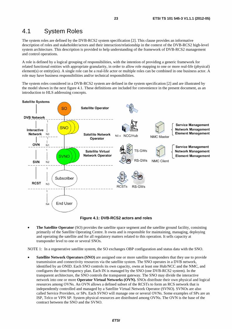
The system roles considered in a DVB-RCS2 system are defined in the system specification [2] and are illustrated by the model shown in the next figure 4.1. These definitions are included for convenience in the present document, as an introduction to HLS addressing concepts.
Figure 4.1: DVB-RCS2 actors and roles
• The Satellite Operator (SO) provides the satellite space segment and the satellite ground facility, consisting primarily of the Satellite Operating Centre. It owns and is responsible for maintaining, managing, deploying and operating the satellite and for all regulatory matters related to this operation. It sells capacity at transponder level to one or several SNOs.
NOTE 1: In a regenerative satellite system, the SO exchanges OBP configuration and status data with the SNO.
• Satellite Network Operators (SNO) are assigned one or more satellite transponders that they use to provide transmission and connectivity resources via the satellite system. The SNO operates in a DVB network, identified by an ONID. Each SNO controls its own capacity, owns at least one Hub/NCC and the NMC, and configures the time/frequency plan. Each IN is managed by the SNO (one DVB-RCS2 system). In the transparent architecture, the SNO controls the transparent gateway. The SNO may divide the interactive network into one or more Operator Virtual Networks (OVN). SNOs distribute their own physical and logical resources among OVNs. An OVN allows a defined subset of the RCSTs to form an RCS network that is independently controlled and managed by a Satellite Virtual Network Operator (SVNO). SVNOs are also called Service Providers, or SPs. Each SVNO will manage one or several OVNs. Some examples of SPs are an ISP, Telco or VPN SP. System physical resources are distributed among OVNs. The OVN is the base of the contract between the SNO and the SVNO.
ETSI
ETSI TS 101 545-3 V1.1.1 (2012-05)24
NOTE 2: For the regenerative systems, there is a master SNO, controlling the Network Operation Centre (for OBP configuration), and secondary SNOs. The master SNO does not necessary use a single NCC/NMC.
• Satellite Virtual Network Operators (SVNO), are assigned one or more Operator Virtual Networks (OVN)/ Each OVN is given some physical (e.g. peak and guaranteed kbps or frequency bandwidth, depending on the system definition) and logical (e.g. one Group_ID, a set of SVN numbers) resources. An active RCST can only be a member of one OVN. This is assigned at logon to the RCS Network. Each OVN is assigned a pool of SVN numbers from which it can allocate SVN-MAC addresses. The SVN concept is used to logically divide the addressing space controlled by the operator. SVNOs sell connectivity services to their subscribers. In a regenerative architecture, a SVNO may also manage one or several GWs.
• A subscriber is connected to the network via an RCST, with the service provided by one SVNO. Although an RCST may belong to only one OVN, it may participate in several SVNs, associated to the same SVNO.
• End-users are the physical person(s) or entity (e.g. application) that use(s) the subscribed satellite services. They use the RCSTs or hosts connected to the RCST LAN interface.
The RCST determines the ONID and INID from the Forward Link acquisition. They are indirectly determined by the start-up Forward Link and the population_Id, configured in advance in the RCST. The RCST understands the combination of {ONID, INID} as the SNO domain.
NOTE 3: A combination of {ONID, INID} identifies the network as an administrative entity to the RCST and thus implicitly, the SNO domain.
The NMC may exist as two principally types in a network, one used by the SNO and one used by the SVNO. The SVNO may have a back end connection to the SNO NMC.
One single terminal may be managed concurrently by one SNO and one SVNO. This applies to the consumer, corporate, SCADA, backhaul and Institutional.. This terminal belongs to the end user that assumes its cost. This subscriber will have one service package with the SNO or SVNO.
A multi-dwelling Satellite Terminal comprises multiple subscribers at a single location that share the terminal to access satellite broadband services. These subscribers belong to different domains or organizations differentiated by IP addressing. The RCST does not belong to one specific end user but to the SVNO. The service packages available to the residents of the multi-dwelling terminal are generally the same as those offered to typical consumers.
4.2 Higher Layer functional modules Each RCST belongs to one RCS Interactive Network. The RCS Interactive Network complies the organization of the ISO/OSI protocol stack with protocol layers grouped into three layers:
• Physical layer (L1), specified by the DVB-RCS2 Lower Layer Specification
• Link layer (L2), partially specified by the DVB-RCS2 Lower Layer Specification
• Network layer and above (L3+), the main focus of this specification.
The RCS Interactive Network is further organized in three planes:
• User-plane (U-plane)
• Control-plane (C-plane)
• Management-plane (M-plane)
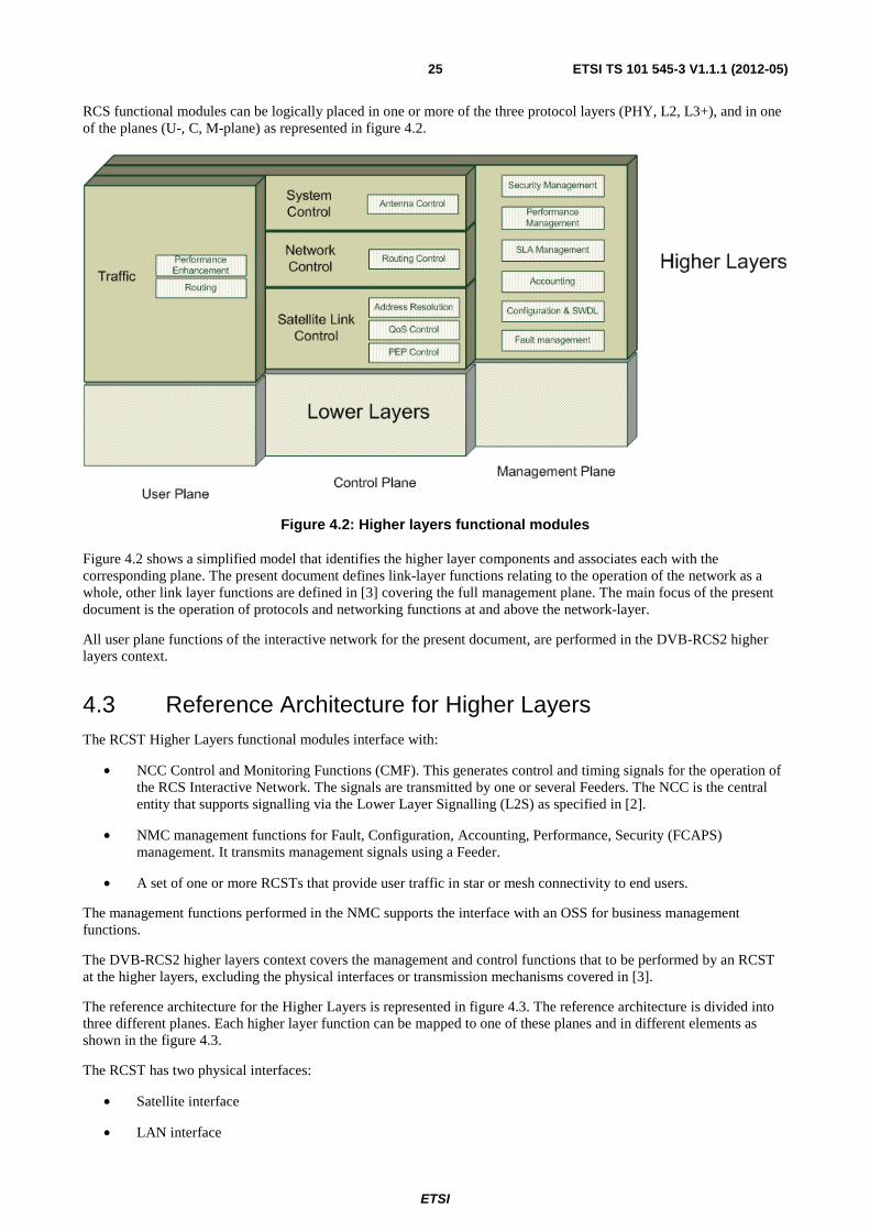
ETSI
ETSI TS 101 545-3 V1.1.1 (2012-05)25
RCS functional modules can be logically placed in one or more of the three protocol layers (PHY, L2, L3+), and in one of the planes (U-, C, M-plane) as represented in figure 4.2.
Figure 4.2: Higher layers functional modules
Figure 4.2 shows a simplified model that identifies the higher layer components and associates each with the corresponding plane. The present document defines link-layer functions relating to the operation of the network as a whole, other link layer functions are defined in [3] covering the full management plane. The main focus of the present document is the operation of protocols and networking functions at and above the network-layer.
All user plane functions of the interactive network for the present document, are performed in the DVB-RCS2 higher layers context.
4.3 Reference Architecture for Higher Layers The RCST Higher Layers functional modules interface with:
• NCC Control and Monitoring Functions (CMF). This generates control and timing signals for the operation of the RCS Interactive Network. The signals are transmitted by one or several Feeders. The NCC is the central entity that supports signalling via the Lower Layer Signalling (L2S) as specified in [2].
• NMC management functions for Fault, Configuration, Accounting, Performance, Security (FCAPS) management. It transmits management signals using a Feeder.
• A set of one or more RCSTs that provide user traffic in star or mesh connectivity to end users.
The management functions performed in the NMC supports the interface with an OSS for business management functions.
The DVB-RCS2 higher layers context covers the management and control functions that to be performed by an RCST at the higher layers, excluding the physical interfaces or transmission mechanisms covered in [3].
The reference architecture for the Higher Layers is represented in figure 4.3. The reference architecture is divided into three different planes. Each higher layer function can be mapped to one of these planes and in different elements as shown in the figure 4.3.
The RCST has two physical interfaces:
• Satellite interface
• LAN interface
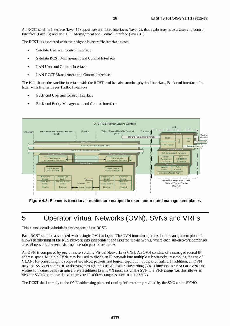
ETSI
ETSI TS 101 545-3 V1.1.1 (2012-05)26
An RCST satellite interface (layer 1) support several Link Interfaces (layer 2), that again may have a User and control Interface (Layer 3) and an RCST Management and Control Interface (layer 3+).
The RCST is associated with their higher layer traffic interface types:
• Satellite User and Control Interface
• Satellite RCST Management and Control Interface
• LAN User and Control Interface
• LAN RCST Management and Control Interface
The Hub shares the satellite interface with the RCST, and has also another physical interface, Back-end interface, the latter with Higher Layer Traffic Interfaces:
• Back-end User and Control Interface
• Back-end Entity Management and Control Interface
Figure 4.3: Elements functional architecture mapped in user, control and management planes
5 Operator Virtual Networks (OVN), SVNs and VRFs This clause details administrative aspects of the RCST.
Each RCST shall be associated with a single OVN at logon. The OVN function operates in the management plane. It allows partitioning of the RCS network into independent and isolated sub-networks, where each sub-network comprises a set of network elements sharing a certain pool of resources.
An OVN is composed by one or more Satellite Virtual Networks (SVNs). An OVN consists of a managed routed IP address space. Multiple SVNs may be used to divide an IP network into multiple subnetworks, resembling the use of VLANs for controlling the scope of broadcast packets and logical separation of the user traffic. In addition, an OVN may use SVNs to control IP addressing through the Virtual Router Forwarding (VRF) function. An SNO or SVNO that wishes to independently assign a private address to an SVN must assign the SVN to a VRF group (i.e. this allows an SNO or SVNO to re-use the same private IP address range as used in other SVNs.
The RCST shall comply to the OVN addressing plan and routing information provided by the SNO or the SVNO.
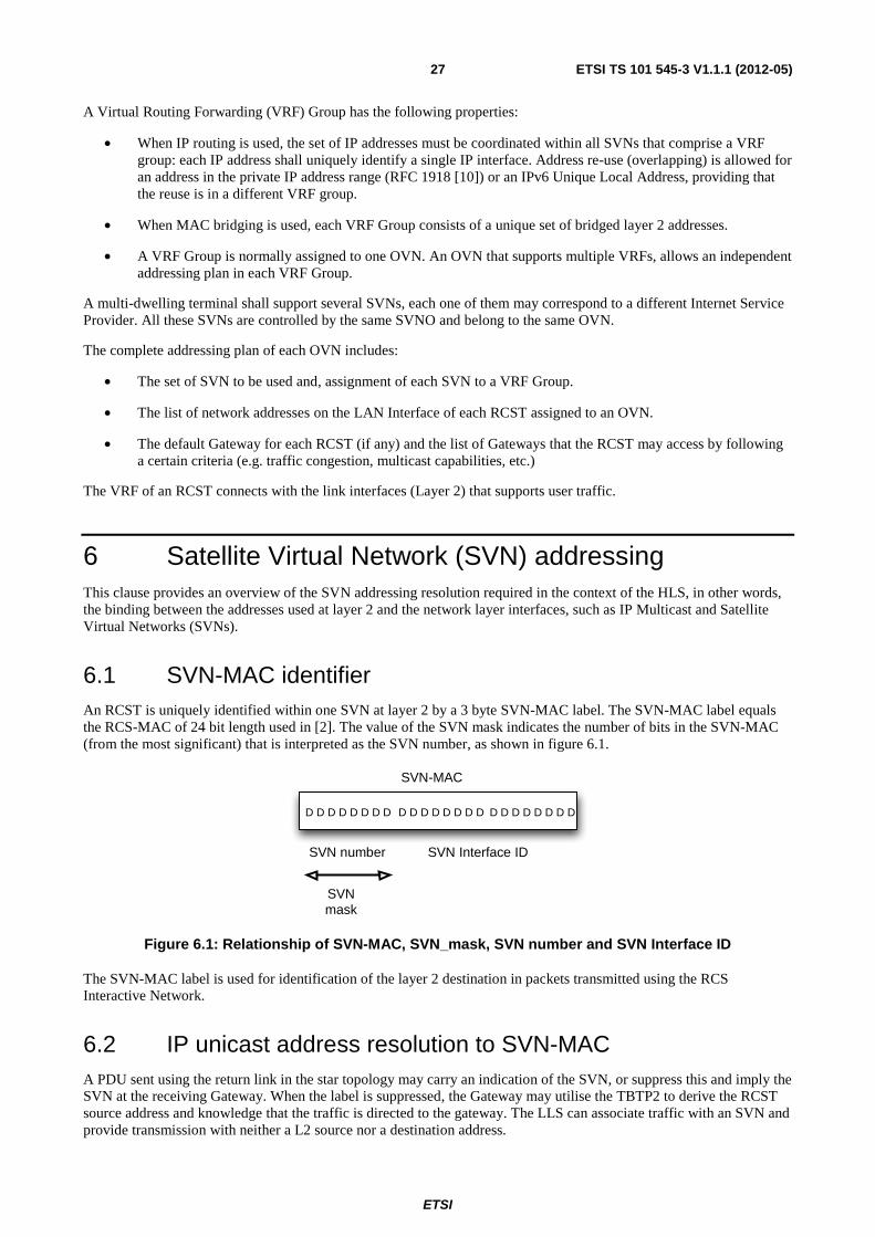
ETSI
ETSI TS 101 545-3 V1.1.1 (2012-05)27
A Virtual Routing Forwarding (VRF) Group has the following properties:
• When IP routing is used, the set of IP addresses must be coordinated within all SVNs that comprise a VRF group: each IP address shall uniquely identify a single IP interface. Address re-use (overlapping) is allowed for an address in the private IP address range (RFC 1918 [10]) or an IPv6 Unique Local Address, providing that the reuse is in a different VRF group.
• When MAC bridging is used, each VRF Group consists of a unique set of bridged layer 2 addresses.
• A VRF Group is normally assigned to one OVN. An OVN that supports multiple VRFs, allows an independent addressing plan in each VRF Group.
A multi-dwelling terminal shall support several SVNs, each one of them may correspond to a different Internet Service Provider. All these SVNs are controlled by the same SVNO and belong to the same OVN.
The complete addressing plan of each OVN includes:
• The set of SVN to be used and, assignment of each SVN to a VRF Group.
• The list of network addresses on the LAN Interface of each RCST assigned to an OVN.
• The default Gateway for each RCST (if any) and the list of Gateways that the RCST may access by following a certain criteria (e.g. traffic congestion, multicast capabilities, etc.)
The VRF of an RCST connects with the link interfaces (Layer 2) that supports user traffic.
6 Satellite Virtual Network (SVN) addressing This clause provides an overview of the SVN addressing resolution required in the context of the HLS, in other words, the binding between the addresses used at layer 2 and the network layer interfaces, such as IP Multicast and Satellite Virtual Networks (SVNs).
6.1 SVN-MAC identifier An RCST is uniquely identified within one SVN at layer 2 by a 3 byte SVN-MAC label. The SVN-MAC label equals the RCS-MAC of 24 bit length used in [2]. The value of the SVN mask indicates the number of bits in the SVN-MAC (from the most significant) that is interpreted as the SVN number, as shown in figure 6.1.
D D D D D D D D D D D D D D D D D D D D D D D D
SVNmask
SVN number SVN Interface ID
SVN-MAC
Figure 6.1: Relationship of SVN-MAC, SVN_mask, SVN number and SVN Interface ID
The SVN-MAC label is used for identification of the layer 2 destination in packets transmitted using the RCS Interactive Network.
6.2 IP unicast address resolution to SVN-MAC A PDU sent using the return link in the star topology may carry an indication of the SVN, or suppress this and imply the SVN at the receiving Gateway. When the label is suppressed, the Gateway may utilise the TBTP2 to derive the RCST source address and knowledge that the traffic is directed to the gateway. The LLS can associate traffic with an SVN and provide transmission with neither a L2 source nor a destination address.
ETSI
ETSI TS 101 545-3 V1.1.1 (2012-05)28
6.2.1 IPv4 address resolution for M and C SVN-MAC
The RCST shall be assigned one SVN-MAC label for management and control, as configured by the SNO during logon (see clause 8). SVN number zero is reserved for the SNO management and control in the OVN to which the RCST belongs. All RCSTs are therefore a member of the zero SVN.
PDUs received by an RCST with the assigned management SVN-MAC label shall be passed for host-processing by the RCST and passed to the control and management function within the higher layers.
A Gateway is able to identify M and C messages by the IPv4 address of the RCST, and therefore the SVN-MAC label needs not be sent on the return link, only the SVN number, since the LLS provides functions to identify the SVN.
The SNO-NMC connects via a management interface (SVN zero) that does not support a User and Control interface.
NOTE: Certain implementations may require the SVN-MAC label sent in the return link to easily identify the RCST for M and C.
6.2.2 Network address resolution to user traffic SVN-MAC
The RCST shall support at least one traffic interface, with a non-zero SVN. An SVNO may configure additional traffic interfaces by assigning additional SVN-MAC labels to an RCST that support this, also with a non-zero SVN. Each RCST traffic interface shall be identified by a SVN-MAC label, unique within the SNO forwarding link traffic multiplex. The SVN-MAC and SVN mask allows an RCST to identify the corresponding SVN number.
The SVNO-NMC connect via a management interface (SVN) that may support User and Control Interface.
NOTE 1: The SNO domain may use one or more multiplex streams. Each multiplex stream specification then indicates a forward link traffic multiplex for the RCS map service as specified in [3].
The RCST shall support SVNO management signalling using any assigned traffic SVN.
Within the OVN an RCST shall be assigned one or more IPv4 address corresponding to the configured SVN-MAC labels. The IPv4 address shall be unique within a VRF Group. In addition, the RCST shall allow the SVN-MAC interface to be assigned an IPv6 address and may support other network addresses.
NOTE 2: An RCST that is assigned multiple SVN-MAC labels corresponding to multiple traffic SVNs will normally also be assigned a separate IP address for each SVN-MAC (e.g. an IPv4 or IPv6 address). These addresses may be presented on separate physical LAN interfaces or separate VLAN sub-interfaces providing connectivity to multiple routed networks.
NOTE 3: The LLS includes mechanisms for SVN identification that allow it to suppress transmission of the SVN-MAC on a return link.
6.2.3 Multicast address resolution to a multicast SVN-MAC
The RCST shall support IP multicast addresses mapping to a SVN-MAC label using a mapping defined per SVN or via an explicit mapping indicated in the MMT2 signalling [2]. A multicast group shall be available to receivers in different SVNs using the shared address space as indicated in MMT2. The layer 2 mapping from an IP group destination address to a L2 SVN-MAC is specified in the LL [3]. This shall be performed using one of the two methods below:
• An implicit mapping based on a hash of the layer 3 network address to one of a range of SVN-MAC multicast labels.
This mapping is independent for each SVN. The SNO therefore defines the size of the mask for each SVN. It is important that multicast network addresses used in SVNs that belong to different VRF Groups may be identical but correspond to different multicast groups and need to be handled separately. This direct mapping is simple, but a restricted range of SVN-MAC addresses increases the risk of aliasing in which more than one independent layer 3 multicast group is mapped to the same layer 2 address. This mapping may be restricted to either IPv4 or IPv6. When both IPv4 and IPv6 are supported, the two sets of addresses may be mapped to the same block of SVN addresses. However this can also result in overlap between IPv4 and IPv6 multicast. This overlap between address ranges does not currently exist when utilising Ethernet and could have unwanted side-effects and the operator is therefore provided with flexibility to separate the two address spaces by utilising one bit in the SVN-MAC to indicate whether the mapping is for IPv4 and IPv6.
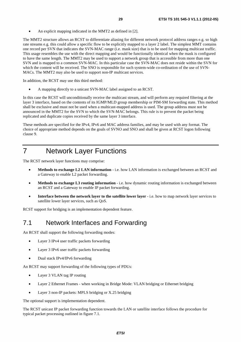
ETSI
ETSI TS 101 545-3 V1.1.1 (2012-05)29
• An explicit mapping indicated in the MMT2 as defined in [2].
The MMT2 structure allows an RCST to differentiate aliasing for different network protocol address ranges e.g. so high rate streams e.g. this could allow a specific flow to be explicitly mapped to a layer 2 label. The simplest MMT contains one record per SVN that indicates the SVN-MAC range (i.e. mask size) that is to be used for mapping multicast traffic. This usage resembles the use with the direct mapping and would be functionally identical when the mask is configured to have the same length. The MMT2 may be used to support a network group that is accessible from more than one SVN and is mapped to a common SVN-MAC. In this particular case the SVN-MAC does not reside within the SVN for which the content will be received. The SNO is responsible for such system-wide co-ordination of the use of SVN-MACs. The MMT2 may also be used to support non-IP multicast services.
In addition, the RCST may use this third method:
• A mapping directly to a unicast SVN-MAC label assigned to an RCST.
In this case the RCST will unconditionally receive the multicast stream, and will perform any required filtering at the layer 3 interface, based on the contents of its IGMP/MLD group membership or PIM-SM forwarding state. This method shall be exclusive and must not be used when a multicast-mapped address is used. The group address must not be announced in the MMT2 for the SVN to which the SVN-MAC belongs. This rule is to prevent the packet being replicated and duplicate copies received by the same layer 3 interface.
These methods are specified for the IPv4, IPv6 and MAC address families, and may be used with any format. The choice of appropriate method depends on the goals of SVNO and SNO and shall be given at RCST logon following clause 9.
7 Network Layer Functions The RCST network layer functions may comprise:
• Methods to exchange L2 LAN information - i.e. how LAN information is exchanged between an RCST and a Gateway to enable L2 packet forwarding.
• Methods to exchange L3 routing information - i.e. how dynamic routing information is exchanged between an RCST and a Gateway to enable IP packet forwarding.
• Interface between the network layer to the satellite lower layer - i.e. how to map network layer services to satellite lower layer services, such as QoS.
RCST support for bridging is an implementation dependent feature.
7.1 Network Interfaces and Forwarding An RCST shall support the following forwarding modes:
• Layer 3 IPv4 user traffic packets forwarding
• Layer 3 IPv6 user traffic packets forwarding
• Dual stack IPv4/IPv6 forwarding
An RCST may support forwarding of the following types of PDUs:
• Layer 3 VLAN tag IP routing
• Layer 2 Ethernet Frames - when working in Bridge Mode: VLAN bridging or Ethernet bridging
• Layer 3 non-IP packets: MPLS bridging or X.25 bridging
The optional support is implementation dependent.
The RCST unicast IP packet forwarding function towards the LAN or satellite interface follows the procedure for typical packet processing outlined in figure 7.1.
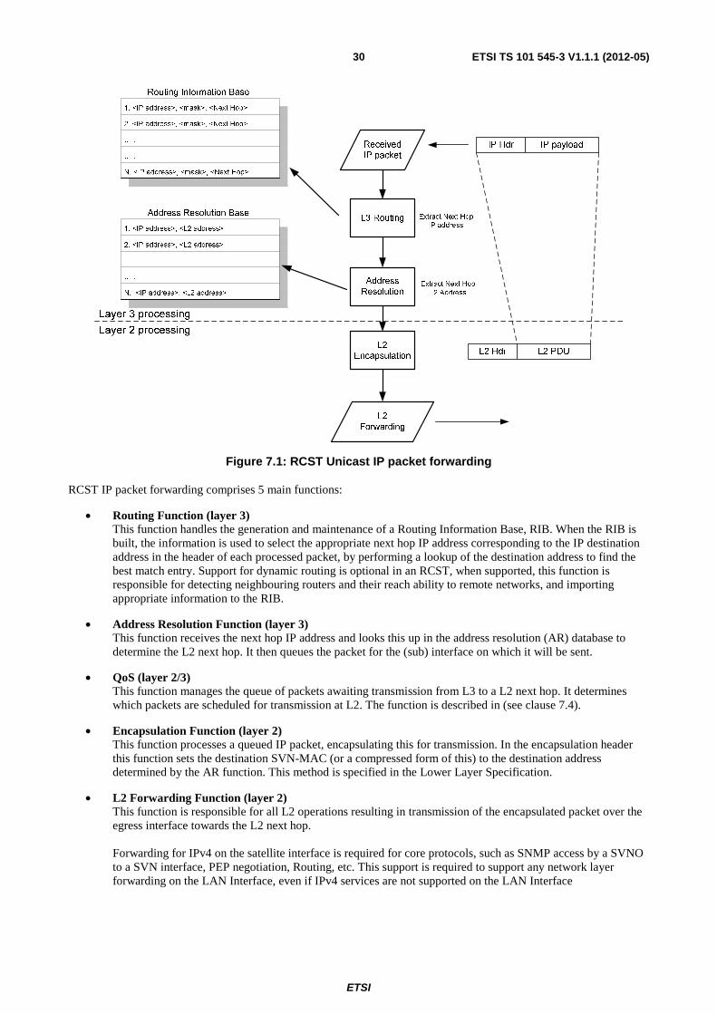
ETSI
ETSI TS 101 545-3 V1.1.1 (2012-05)30
Figure 7.1: RCST Unicast IP packet forwarding
RCST IP packet forwarding comprises 5 main functions:
• Routing Function (layer 3) This function handles the generation and maintenance of a Routing Information Base, RIB. When the RIB is built, the information is used to select the appropriate next hop IP address corresponding to the IP destination address in the header of each processed packet, by performing a lookup of the destination address to find the best match entry. Support for dynamic routing is optional in an RCST, when supported, this function is responsible for detecting neighbouring routers and their reach ability to remote networks, and importing appropriate information to the RIB.
• Address Resolution Function (layer 3) This function receives the next hop IP address and looks this up in the address resolution (AR) database to determine the L2 next hop. It then queues the packet for the (sub) interface on which it will be sent.
• QoS (layer 2/3) This function manages the queue of packets awaiting transmission from L3 to a L2 next hop. It determines which packets are scheduled for transmission at L2. The function is described in (see clause 7.4).
• Encapsulation Function (layer 2) This function processes a queued IP packet, encapsulating this for transmission. In the encapsulation header this function sets the destination SVN-MAC (or a compressed form of this) to the destination address determined by the AR function. This method is specified in the Lower Layer Specification.
• L2 Forwarding Function (layer 2) This function is responsible for all L2 operations resulting in transmission of the encapsulated packet over the egress interface towards the L2 next hop. Forwarding for IPv4 on the satellite interface is required for core protocols, such as SNMP access by a SVNO to a SVN interface, PEP negotiation, Routing, etc. This support is required to support any network layer forwarding on the LAN Interface, even if IPv4 services are not supported on the LAN Interface
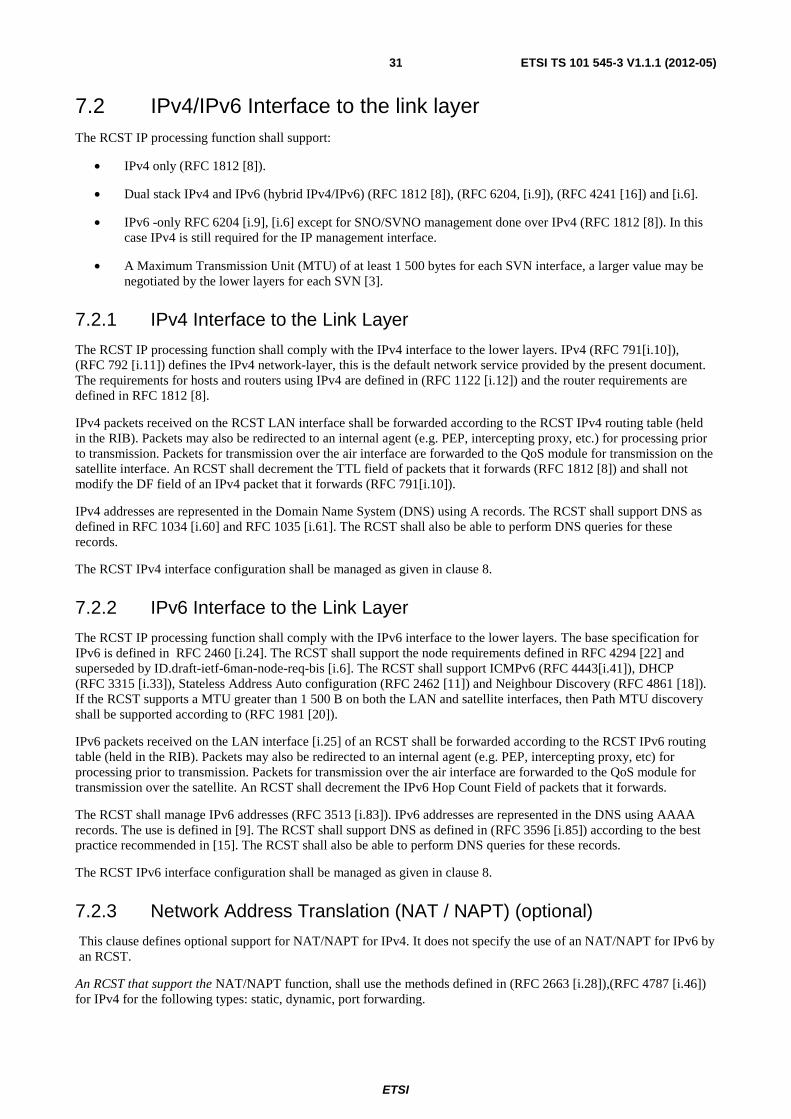
ETSI
ETSI TS 101 545-3 V1.1.1 (2012-05)31
7.2 IPv4/IPv6 Interface to the link layer The RCST IP processing function shall support:
• IPv4 only (RFC 1812 [8]).
• Dual stack IPv4 and IPv6 (hybrid IPv4/IPv6) (RFC 1812 [8]), (RFC 6204, [i.9]), (RFC 4241 [16]) and [i.6].
• IPv6 -only RFC 6204 [i.9], [i.6] except for SNO/SVNO management done over IPv4 (RFC 1812 [8]). In this case IPv4 is still required for the IP management interface.
• A Maximum Transmission Unit (MTU) of at least 1 500 bytes for each SVN interface, a larger value may be negotiated by the lower layers for each SVN [3].
7.2.1 IPv4 Interface to the Link Layer
The RCST IP processing function shall comply with the IPv4 interface to the lower layers. IPv4 (RFC 791[i.10]), (RFC 792 [i.11]) defines the IPv4 network-layer, this is the default network service provided by the present document. The requirements for hosts and routers using IPv4 are defined in (RFC 1122 [i.12]) and the router requirements are defined in RFC 1812 [8].
IPv4 packets received on the RCST LAN interface shall be forwarded according to the RCST IPv4 routing table (held in the RIB). Packets may also be redirected to an internal agent (e.g. PEP, intercepting proxy, etc.) for processing prior to transmission. Packets for transmission over the air interface are forwarded to the QoS module for transmission on the satellite interface. An RCST shall decrement the TTL field of packets that it forwards (RFC 1812 [8]) and shall not modify the DF field of an IPv4 packet that it forwards (RFC 791[i.10]).
IPv4 addresses are represented in the Domain Name System (DNS) using A records. The RCST shall support DNS as defined in RFC 1034 [i.60] and RFC 1035 [i.61]. The RCST shall also be able to perform DNS queries for these records.
The RCST IPv4 interface configuration shall be managed as given in clause 8.
7.2.2 IPv6 Interface to the Link Layer
The RCST IP processing function shall comply with the IPv6 interface to the lower layers. The base specification for IPv6 is defined in RFC 2460 [i.24]. The RCST shall support the node requirements defined in RFC 4294 [22] and superseded by ID.draft-ietf-6man-node-req-bis [i.6]. The RCST shall support ICMPv6 (RFC 4443[i.41]), DHCP (RFC 3315 [i.33]), Stateless Address Auto configuration (RFC 2462 [11]) and Neighbour Discovery (RFC 4861 [18]). If the RCST supports a MTU greater than 1 500 B on both the LAN and satellite interfaces, then Path MTU discovery shall be supported according to (RFC 1981 [20]).
IPv6 packets received on the LAN interface [i.25] of an RCST shall be forwarded according to the RCST IPv6 routing table (held in the RIB). Packets may also be redirected to an internal agent (e.g. PEP, intercepting proxy, etc) for processing prior to transmission. Packets for transmission over the air interface are forwarded to the QoS module for transmission over the satellite. An RCST shall decrement the IPv6 Hop Count Field of packets that it forwards.
The RCST shall manage IPv6 addresses (RFC 3513 [i.83]). IPv6 addresses are represented in the DNS using AAAA records. The use is defined in [9]. The RCST shall support DNS as defined in (RFC 3596 [i.85]) according to the best practice recommended in [15]. The RCST shall also be able to perform DNS queries for these records.
The RCST IPv6 interface configuration shall be managed as given in clause 8.
7.2.3 Network Address Translation (NAT / NAPT) (optional)
This clause defines optional support for NAT/NAPT for IPv4. It does not specify the use of an NAT/NAPT for IPv6 by an RCST.
An RCST that support the NAT/NAPT function, shall use the methods defined in (RFC 2663 [i.28]),(RFC 4787 [i.46]) for IPv4 for the following types: static, dynamic, port forwarding.
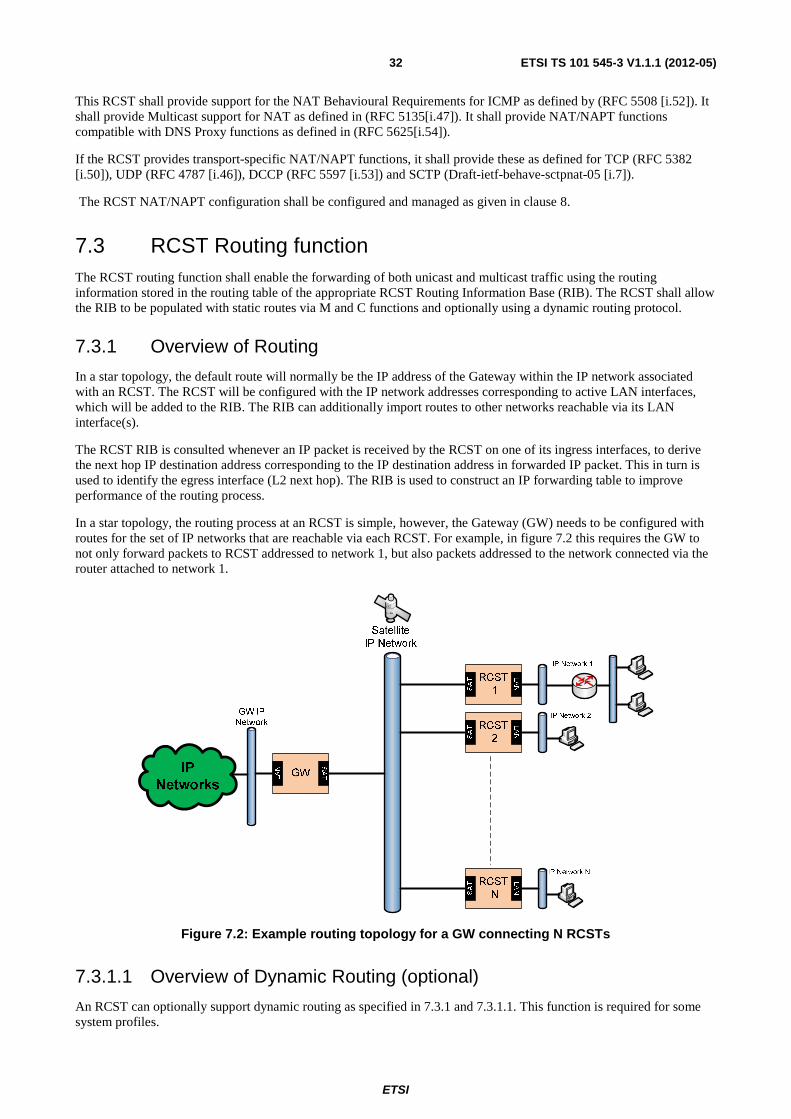
ETSI
ETSI TS 101 545-3 V1.1.1 (2012-05)32
This RCST shall provide support for the NAT Behavioural Requirements for ICMP as defined by (RFC 5508 [i.52]). It shall provide Multicast support for NAT as defined in (RFC 5135[i.47]). It shall provide NAT/NAPT functions compatible with DNS Proxy functions as defined in (RFC 5625[i.54]).
If the RCST provides transport-specific NAT/NAPT functions, it shall provide these as defined for TCP (RFC 5382 [i.50]), UDP (RFC 4787 [i.46]), DCCP (RFC 5597 [i.53]) and SCTP (Draft-ietf-behave-sctpnat-05 [i.7]).
The RCST NAT/NAPT configuration shall be configured and managed as given in clause 8.
7.3 RCST Routing function The RCST routing function shall enable the forwarding of both unicast and multicast traffic using the routing information stored in the routing table of the appropriate RCST Routing Information Base (RIB). The RCST shall allow the RIB to be populated with static routes via M and C functions and optionally using a dynamic routing protocol.
7.3.1 Overview of Routing
In a star topology, the default route will normally be the IP address of the Gateway within the IP network associated with an RCST. The RCST will be configured with the IP network addresses corresponding to active LAN interfaces, which will be added to the RIB. The RIB can additionally import routes to other networks reachable via its LAN interface(s).
The RCST RIB is consulted whenever an IP packet is received by the RCST on one of its ingress interfaces, to derive the next hop IP destination address corresponding to the IP destination address in forwarded IP packet. This in turn is used to identify the egress interface (L2 next hop). The RIB is used to construct an IP forwarding table to improve performance of the routing process.
In a star topology, the routing process at an RCST is simple, however, the Gateway (GW) needs to be configured with routes for the set of IP networks that are reachable via each RCST. For example, in figure 7.2 this requires the GW to not only forward packets to RCST addressed to network 1, but also packets addressed to the network connected via the router attached to network 1.
SAT
LAN
SAT
LAN
SAT
LAN
LAN
SAT
Figure 7.2: Example routing topology for a GW connecting N RCSTs
7.3.1.1 Overview of Dynamic Routing (optional)
An RCST can optionally support dynamic routing as specified in 7.3.1 and 7.3.1.1. This function is required for some system profiles.
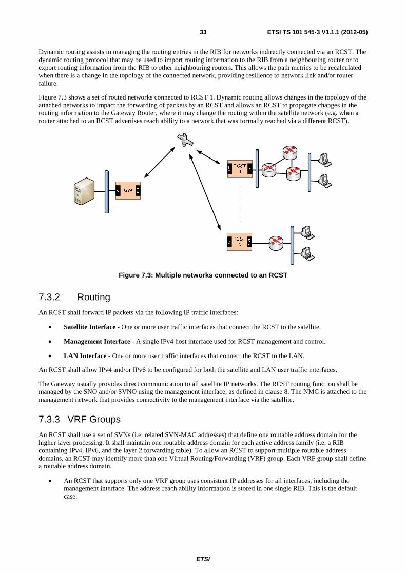
ETSI
ETSI TS 101 545-3 V1.1.1 (2012-05)33
Dynamic routing assists in managing the routing entries in the RIB for networks indirectly connected via an RCST. The dynamic routing protocol that may be used to import routing information to the RIB from a neighbouring router or to export routing information from the RIB to other neighbouring routers. This allows the path metrics to be recalculated when there is a change in the topology of the connected network, providing resilience to network link and/or router failure.
Figure 7.3 shows a set of routed networks connected to RCST 1. Dynamic routing allows changes in the topology of the attached networks to impact the forwarding of packets by an RCST and allows an RCST to propagate changes in the routing information to the Gateway Router, where it may change the routing within the satellite network (e.g. when a router attached to an RCST advertises reach ability to a network that was formally reached via a different RCST).
SAT
LAN
SAT
LAN
LAN
SAT
Figure 7.3: Multiple networks connected to an RCST
7.3.2 Routing
An RCST shall forward IP packets via the following IP traffic interfaces:
• Satellite Interface - One or more user traffic interfaces that connect the RCST to the satellite.
• Management Interface - A single IPv4 host interface used for RCST management and control.
• LAN Interface - One or more user traffic interfaces that connect the RCST to the LAN.
An RCST shall allow IPv4 and/or IPv6 to be configured for both the satellite and LAN user traffic interfaces.
The Gateway usually provides direct communication to all satellite IP networks. The RCST routing function shall be managed by the SNO and/or SVNO using the management interface, as defined in clause 8. The NMC is attached to the management network that provides connectivity to the management interface via the satellite.
7.3.3 VRF Groups
An RCST shall use a set of SVNs (i.e. related SVN-MAC addresses) that define one routable address domain for the higher layer processing. It shall maintain one routable address domain for each active address family (i.e. a RIB containing IPv4, IPv6, and the layer 2 forwarding table). To allow an RCST to support multiple routable address domains, an RCST may identify more than one Virtual Routing/Forwarding (VRF) group. Each VRF group shall define a routable address domain.
• An RCST that supports only one VRF group uses consistent IP addresses for all interfaces, including the management interface. The address reach ability information is stored in one single RIB. This is the default case.
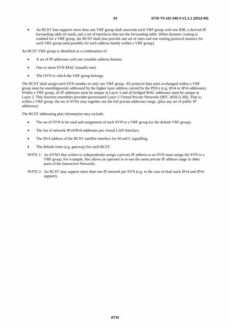
ETSI
ETSI TS 101 545-3 V1.1.1 (2012-05)34
• An RCST that supports more than one VRF group shall associate each VRF group with one RIB, a derived IP forwarding table (if used), and a set of interfaces that use the forwarding table. When dynamic routing is enabled for a VRF group, the RCST shall also provide one set of rules and one routing protocol instance for each VRF group (and possibly for each address family within a VRF group).
An RCST VRF group is identified as a combination of:
• A set of IP addresses with one routable address domain.
• One or more SVN-MAC (usually one).
• The OVN to which the VRF group belongs.
The RCST shall assign each SVN number to only one VRF group. All protocol data units exchanged within a VRF group must be unambiguously addressed by the higher layer address carried by the PDUs (e.g. IPv4 or IPv6 addresses). Within a VRF group, all IP addresses must be unique at Layer 3 and all bridged MAC addresses must be unique at Layer 2. This function resembles provider-provisioned Layer 3 Virtual Private Networks (RFC 4026 [i.38]). That is, within a VRF group, the set of SVNs may together use the full private addresses range, (plus any set of public IP addresses).
The RCST addressing plan information may include:
• The set of SVN to be used and assignment of each SVN to a VRF group (or the default VRF group).
• The list of network IPv4/IPv6 addresses per virtual LAN Interface.
• The IPv4 address of the RCST satellite interface for M and C signalling.
• The default route (e.g. gateway) for each RCST.
NOTE 1: An SVNO that wishes to independently assign a private IP address to an SVN must assign the SVN to a VRF group. For example, this allows an operator to re-use the same private IP address range in other parts of the Interactive Network).
NOTE 2: An RCST may support more than one IP network per SVN (e.g. in the case of dual stack IPv4 and IPv6 support).
ETSI
ETSI TS 101 545-3 V1.1.1 (2012-05)35
Figure 7.4: OVN, SVNs and VRFs domains
A bridged network can also utilise a VRF group, to ensure independent use of the MAC address space. This also supports situations where an operator wishes to allow the same MAC address to appear more than once within an interactive network.
The following examples illustrate the SVNO usage of VRF groups and multiple SVNs:
• An SVNO may use a single VRF group with one address space. Multiple SVNs may be used to segregate end user network traffic. This SVNO may allocate unique network addresses to each SVN-MAC that it supports. This addressing architecture could, for example, correspond to the assignment of globally routable IP addresses, or a single use of the private address space within the satellite interactive network.
• An SVNO may use multiple VRF groups. The SVNO is only required to allocate a network address that is unique within a VRF group. This addressing architecture allows the SVNO to assign customer networks to separate SVNs, each in a separate VRF group. In this case, the entire private address may be made available to each customer network. Routing between these address spaces would require NAT or NAPT to translate addresses between the VRF groups and also to/from the globally routed public Internet.
7.3.4 VLAN Support (optional)
The RCST may support Virtual LANS (VLANs) on the LAN interface to isolate the traffic belonging to one logical L2 network from a different logical L2 network.
ETSI
ETSI TS 101 545-3 V1.1.1 (2012-05)36
When a LAN interface supports interpretation of an IEEE 802.1D [i.59] tag at the LAN ingress interface, the VLAN ID field in the tag shall denote the VLAN assigned to the frame. Untagged frames may be supported by an interface that also supports 802.1D format frames. These untagged frames shall be associated with a default VLAN ID. An RCST shall interpret a VLAN at the IP level as a subnetwork, with traffic from different VLANs being forwarded by an IP router via different subnet interfaces.
An RCST may be configured so that traffic received from the satellite interface may be transmitted on a LAN (sub) egress interface with a correspondingly configured VLAN tag.
In this mode IP routing is agnostic to the value of the VLAN tag (if any) associated with a LAN interface and the tag value is removed prior to transmission over the satellite interface. Therefore there is no implicit coordination of the VLAN-IDs used at the ingress and egress LAN interfaces.
7.3.4.1 VLAN tagged IP routing (optional)
An RCST may optionally support a mode that forwards an IP packet with an associated L2 IEEE 802.1D [i.59] tag, both from and to an RCST that operates as an IP router.
This mode permits a satellite network router to forward frames at the network layer (e.g. IPv4 or IPv6 routing) and simultaneously preserve the Ethernet Tag Control Identifier Field in 802.1D format across the satellite network, extracted from the MAC-layer header of each IP packet received on the ingress LAN interface. The Tag Control Identifier includes the L2 VLAN ID and Priority Code Point, PCP. This allows the received tag value to be re-inserted at the egress LAN interface when the packet leaves the satellite network.
When the routing function forwards an IP packet over the satellite interface in this mode, the Ethernet Tag Control Identifier Field shall be forwarded by including a tag extension header placed directly before the IP network header. The presence of this extension header is indicated by the Protocol Type value 0x8100. In this mode, the extension header is not preceded by the 6 byte MAC addresses on the satellite interface as it is on the LAN Interface. This encapsulation format can be used with GSE and with the Return Link encapsulation. The Return Link encapsulation may alternatively use a compressed type value (LLS) (0x0F or 0x31). The latter value indicates omission of the Protocol Type field from the 802.1D format, requiring the receiver to synthesize it before submission to the egress LAN (e.g. based on the version field carried in the first byte of the IP header).
An RCST in this mode shall also support forwarding of untagged IP packets by the IP router (i.e. an IP packet received at the LAN ingress without IEEE 802.1D [i.59] tag). These packets shall be forwarded without a tag extension header, using the routing method described in clause 7.3.5.
An RCST shall not forward IP packets with a L2 broadcast address using this mode. IP packets sent with a L2 broadcast address (e.g. DHCP Request messages) are processed by the local router, as are packets directed to the IP address of a router interface (e.g. ICMP, routing), as in clause 7.3.5.
This option does not forward the content of Ethernet frames that do not directly encapsulate IP packets, i.e. Frames with a Protocol Type value of 0x8100, but with other content than IP.
An RCST that is configured to assign values to a VLAN tag on transmission using the LAN interface shall perform this mapping for all traffic, including any packets forwarded with this tag extension header. When the IEEE 802.1D [i.59] tag assignment is configured, the RCST shall set the transmitted Ethernet Tag Control Identifier Field based on the router/interface configuration (e.g. by mapping the DSCP). This overrides then an Ethernet Tag Control Identifier Field transported over the satellite interface (this tag could have been dropped at the satellite network ingress).
NOTE: When an RCST uses this mode, VLAN IDs will be transported to the gateway from the ingress LAN. Correct operation will rely upon consistent handling of the VLAN IDs associated with packets from multiple RCSTs. This has implications on the configuration of network protocols at the gateway, such as OSPF, and this may require use of traffic separation techniques such as use of VRF groups, VLAN tags, or provider backbone bridges at the gateway.
ETSI
ETSI TS 101 545-3 V1.1.1 (2012-05)37
7.3.5 IPv4 Static Unicast Route Configuration
The RCST IP routing function shall be able to receive IPv4 static routing information from the SNO or the SVNO for each active SVN through the satellite interface. This information is used to populate the RIB.
The IPv4 static routing information comprises a set of route entries. Each route entry shall include the following fields specified in the IP forwarding table MIB as given in (RFC 4292 [i.39]). This information is a part of the RCST configuration for the VRF group associated with one or more SVNs and shall be managed as defined in clause 8.
7.3.6 IPv4 Dynamic Routing Configuration (Optional)
The RCST may optionally support a dynamic IPv4 routing protocol either by routing interactions though a satellite or LAN interface.
When dynamic routing is supported and enabled, the received routing information is used along with configuration information to populate the RCST RIB with IPv4 information. If this function is not enabled, the RCST shall discard all IP packets that carry routing protocol messages.
An RCST that provides the dynamic routing function for IPv4 on the LAN interface shall support OSPF (RFC 2328 [i.18]). It may also be configured to support other routing protocols such as RIPv2 (RFC 2453 [i.23]), IS-IS (RFC 1142 [i.13]).
The RCST OSPF function shall start as soon as there is IP connectivity via a user traffic interface across the SVN network. In star transparent scenarios, the RCST OSPF configuration shall indicate that the Gateway is the OSPF Designated Router (DR) for the satellite IP network.
NOTE: The DR must filter this routing information according to its assigned addressing plan (that is, it should only import routes that are consistent with the addressing using within the SVN/OVN assigned to the RCST within a single VRF group).
7.3.7 IPv4 Multicast
The RCST shall support the use of IPv4 multicast forwarding of traffic (RFC 1112 [19] from the satellite interface to the LAN interface(s). It shall also support IPv4 multicast forwarding of traffic from the LAN interface to the satellite interface(s), transported to the GW. This includes Administratively Scoped Multicast (RFC 2365 [i.22]) and Source-Specific Multicast (RFC 4607 [i.44], RFC 4608 [i.45]).
In IPv4, the Internet Group Management Protocol (IGMP) is used to discover multicast listeners (hosts that wish to receive multicast packets destined for specific multicast addresses) on directly attached links, include the RCST LAN interfaces.
The RCST IPv4 multicast functions:
• shall support satellite IPv4 multicast forwarding (multicast reception), being enabled / disabled by configuration (see clause 8);
• shall support static multicast configuration, as describes in clause 8;
• shall support IGMPv2 (RFC 2236 [i.17]) on each LAN interface;
• may also support IGMPv3 (RFC 3376 [i.34]) or IGMPv3 Lite RFC 5790 [i.98] on each LAN interface;
• shall support IPv4 multicast transmission enable / disable by configuration (see clause 8);
• may optionally support IPv4 multicast routing using PIM-SM (RFC 4601[i.43]) on a LAN interface configured by management (see clause 8);
• an RCST that supports dynamic multicast management may also support a dynamic multicast routing protocol on the LAN interface. In this case, the RCST shall support Protocol Independent Multicast (PIM) in the sparse mode (RFC 4601[i.43]) as the multicast routing protocol and shall provide methods to manage a Multicast RIB (MRIB).
ETSI
ETSI TS 101 545-3 V1.1.1 (2012-05)38
7.3.8 IPv6 static unicast route configuration
The RCST IP routing function shall be able to receive IPv6 static routing information from the SNO or the SVNO for each active SVN through the satellite interface. This information is used to populate the RIB with IPv6 information.
The IPv4 static routing information comprises a set of route entries. Each route entry shall include the fields specified in the IP forwarding table MIB as given in (RFC 4292 [i.39]). This information is a part of the RCST configuration for the VRF group associated with one or more SVNs and shall be managed as defined in clause 8.
7.3.9 Dynamic IPv4 Multicast across satellite (Optional)
The RCST may optionally support dynamic IPv4 multicast membership across the satellite interface, this requires that RCST supports either an IGMP-Proxy Agent (RFC 4605 [17]) plus the adaptations required for the satellite environment as detailed in [7] or supports PIM-SM (RFC 4601[i.43]).
7.3.10 IPv6 Dynamic Routing Configuration (Optional)
The RCST may optionally support a dynamic IPv6 routing protocol either by routing interactions though a satellite or LAN interface.
When dynamic routing is supported and enabled, the received routing information is used along with configuration information to populate the RCST RIB with IPv6 information. If this function is not enabled, the RCST shall discard all IP packets that carry routing protocol messages.
An RCST that provides the dynamic routing function for IPv6 on the LAN interface shall support OSPF (RFC 5340 [i.49]).
Clause 7.3.6 provides information about the use of OSPF on the satellite interface.
7.3.11 IPv6 Multicast
The RCST shall support the use of IPv6 multicast forwarding of traffic from the satellite interface to the LAN interface(s). It shall also support IPv6 multicast forwarding of traffic from the LAN interface to the satellite interface(s), transported to the GW.
In IPv6 Multicast Listener Discovery (MLD, MLDv2 (RFC 3810 [i.37]), or MLDv2 lite (RFC 5790 [i.98]) protocol for IPv6 is used to discover multicast listeners (hosts that wish to receive multicast packets destined for specific multicast addresses) on directly attached links, include the RCST LAN interfaces.
The RCST IPv6 multicast functions:
• shall support satellite IPv6 multicast forwarding for the institutional RCST profile [2], and must support static multicast configuration for each active SVN. For the rest of RCST profiles, IPv6 multicast forwarding in the return channel is optional;
• shall support static multicast configuration, (see clause 8);
• shall support MLDv2 (RFC 3810 [i.37]) or MLDv2 Lite (RFC 5790 [i.98]) on each LAN interface;
• shall support IPv6 multicast transmission enable / disable by configuration, (see clause 8);
• may optionally support IPv6 multicast routing using PIM-SM (RFC 4601 [i.43]) on a LAN interface configured by management, (see clause 8);
• an RCST that supports dynamic multicast management may also support a dynamic multicast routing protocol on the LAN interface. In this case, the RCST shall support Protocol Independent Multicast (PIM) in the sparse mode (RFC 4601[i.43]) as the multicast routing protocol and shall provide methods to manage a Multicast RIB (MRIB);
The RCST IPv6 multicast routing configuration shall be configured and managed as given in clause 8.
ETSI
ETSI TS 101 545-3 V1.1.1 (2012-05)39
7.3.12 Dynamic IPv6 Multicast across satellite (Optional)
The RCST may optionally support dynamic IPv6 multicast membership across the satellite interface, this requires that RCST supports either an MLD-Proxy Agent (RFC 4605 [17]) or supports PIM-SM (RFC 4601 [i.43]).
7.3.13 MPLS
Multi Protocol Label Switching (MPLS) is defined in (RFC 3031 [i.71]) and (RFC 4364 [i.96]). It operates at the boundary between L2 and L3, providing unidirectional connections known as Label Switched Paths (LSP). MPLS encapsulates IP and other traffic by adding an encapsulation header that includes an MPLS label. The use of the labels is controlled by one of the available techniques: LDP (RFC 5036 [i.97]), RSVP (RFC 2205 [i.16]), or BGP-4 (RFC 4271 [i.94]). The MPLS labels have only local significance at a specific interface. The set of IP packets that are forwarded over a given LSP belongs to the same Forwarding Equivalence Class (FEC), and should receive the same treatment by the network.
7.3.13.1 MPLS support in the RCST (Optional)
An RCST may optionally support IP-based transport of MPLS packets (RFC 4023 [i.91]) across the Operator Virtual Network. This transports MPLS signalling and data flows across the satellite interactive network. An RCST that supports this mode shall transparently forward IP packets with an IPv4 Protocol Number field or the IPv6 Next Header field set to 137. It shall assign MPLS packets with a specific FEC to a single HLS PHB group and HL service (RFC 3270 [i.72]). It may similarly forward IP packets that use the Generic Routing Encapsulation (RFC 2784 [i.70]) with a type of 0x8847 or 0x8848. In this mode, the RCST does not interact with the MPLS control plane.
An RCST connected to an MPLS network may also operate as a LSR (Label Switched Router) connected via the LAN interface to a standard LSR or LER. This requires MPLS signalling to be intercepted and processed by the RCST. It also requires an RCST to switch frames from/to the LAN Interface with a type of 0x8847 or 0x8848 (RFC 3031 [i.71]). These frames may be sent on the satellite interface using the standard type value or the compressed type of 0x13 or 0x14, corresponding respectively to 0x8847 and 0x8848. An RCST that supports this function may implement M and C functions that enhance measurement and control for the MPLS traffic (RFC 2702 [i.69]), allowing each LSP to be mapped to an appropriate HL service.
The RCST MPLS configuration shall be configured and managed as described in clause 8.
7.4 Quality of Service The RCST shall support QoS mechanisms both at layer 2 and at layer 3. This clause describes the RCST QoS model in terms of QoS definitions and the RCST QoS cardinality model. The RCST QoS requirements will be composed by:
- QoS elements definitions
- RCST HL QoS model mapping to LL (cardinality diagram)
- RCST QoS classification functions
An RCST shall support traffic differentiation according to DiffServ (RFC 2474 [i.26], RFC 2475[i.27] RFC 3086 [i.30], RFC 3260 [i.32]) for differentiation of the traffic transmitted towards the satellite.
A host originating a flow may not provide explicit QoS signalling, but may use a session-layer protocol to co-ordinate the communication. A signalling proxy at the RCST may snoop these session layer control messages to infer a QoS requirement. The QoS is instead inferred from session characteristics such as the choice of codec (e.g. snooping SIP signalling for a VoIP call to determine the encoding rate chosen by an application or interception of a multimedia request using HTTP). Intercepting proxies are described in clause 9.
7.4.1 RCST Higher Layer QoS Model
The RCST QoS function applies to all the user traffic in the same connectivity aggregate that must be transmitted sharing a common transmission channel. The mapping of user traffic to a connectivity aggregate is responsibility of the forwarding and routing functions for the RCST.
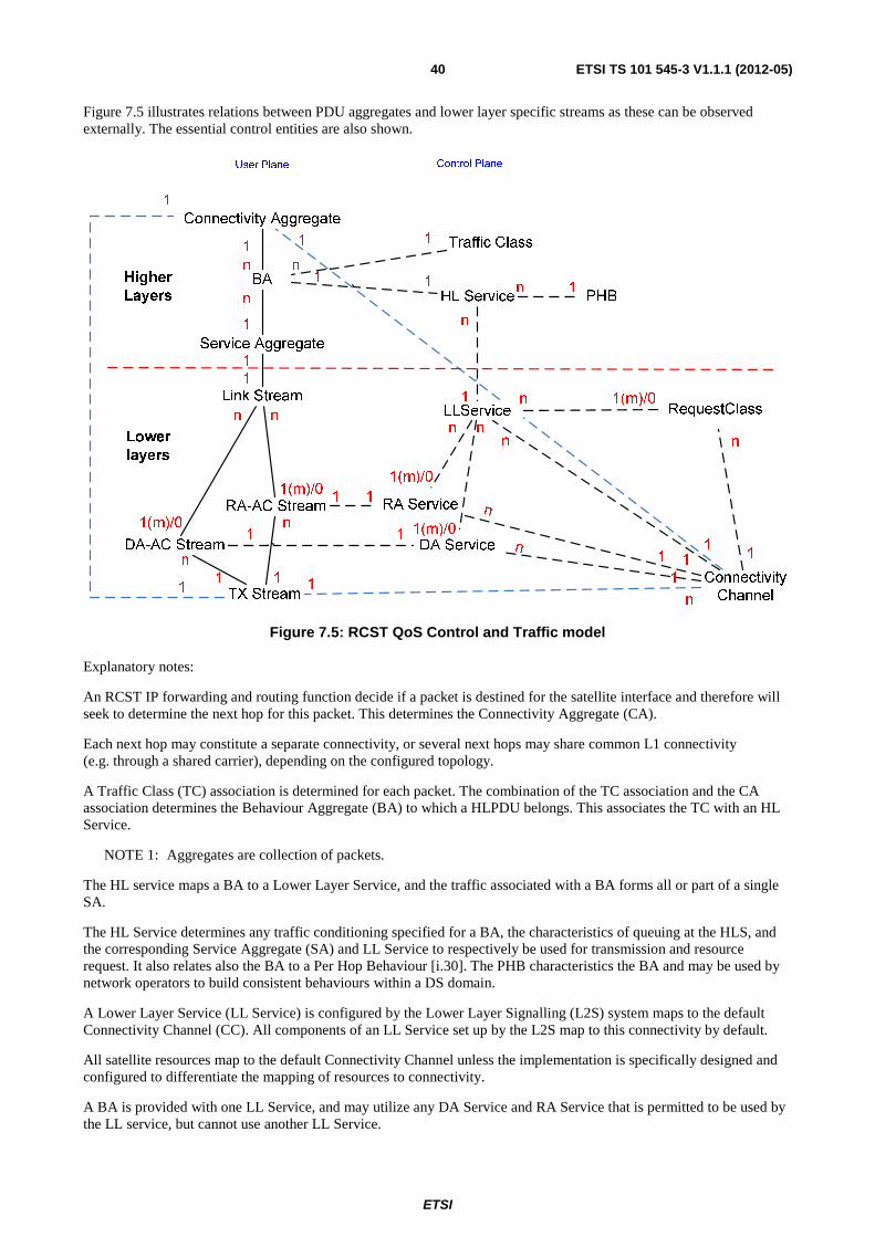
ETSI
ETSI TS 101 545-3 V1.1.1 (2012-05)40
Figure 7.5 illustrates relations between PDU aggregates and lower layer specific streams as these can be observed externally. The essential control entities are also shown.
Traffic Class
BA
LLService RequestClass
DA-AC Stream
RA-AC Stream
1(m)/0
1
1
n
1
1
n n
1(m)/0
n
1
n
User Plane Control Plane
Higher
Layers
Lower
layers
HL Service
Service Aggregate
1
1(m)/0
RA Service
DA Service
1(m)/0n
n
1(m)/0
Link Stream
1 1
1 1
n
1
PHBn 1
Connectivity
Channel
111
1
n
n
n
n
1
Connectivity Aggregate
n
1 1
TX Stream11
n
n
1
1n
1
Figure 7.5: RCST QoS Control and Traffic model
Explanatory notes:
An RCST IP forwarding and routing function decide if a packet is destined for the satellite interface and therefore will seek to determine the next hop for this packet. This determines the Connectivity Aggregate (CA).
Each next hop may constitute a separate connectivity, or several next hops may share common L1 connectivity (e.g. through a shared carrier), depending on the configured topology.
A Traffic Class (TC) association is determined for each packet. The combination of the TC association and the CA association determines the Behaviour Aggregate (BA) to which a HLPDU belongs. This associates the TC with an HL Service.
NOTE 1: Aggregates are collection of packets.
The HL service maps a BA to a Lower Layer Service, and the traffic associated with a BA forms all or part of a single SA.
The HL Service determines any traffic conditioning specified for a BA, the characteristics of queuing at the HLS, and the corresponding Service Aggregate (SA) and LL Service to respectively be used for transmission and resource request. It also relates also the BA to a Per Hop Behaviour [i.30]. The PHB characteristics the BA and may be used by network operators to build consistent behaviours within a DS domain.
A Lower Layer Service (LL Service) is configured by the Lower Layer Signalling (L2S) system maps to the default Connectivity Channel (CC). All components of an LL Service set up by the L2S map to this connectivity by default.
All satellite resources map to the default Connectivity Channel unless the implementation is specifically designed and configured to differentiate the mapping of resources to connectivity.
A BA is provided with one LL Service, and may utilize any DA Service and RA Service that is permitted to be used by the LL service, but cannot use another LL Service.
ETSI
ETSI TS 101 545-3 V1.1.1 (2012-05)41
The Service Aggregate (SA) is the sequence of Higher Layer PDUs (HLPDU) sent via a Link Stream (LS). The SA sequence is a multiplex of HLPDUs of the different BAs that map to the same SA.
The Link Stream (LS) is the sequence of Payload-adapted PDUs (PPDUs) hold the sequence of HLPDUs for the associated SA and may be associated to a logical flow of RLE/GSE traffic packets from the RCST or NCC/GW into the satellite network. All packets from one Link Stream have the same level of Precedence/Priority for layer 2 scheduling. The PPDUs in an LS may be multiplexed with PPDUs that belong to another LS. PPDUs are individually sized to fit within the available unoccupied Frame PDU (FPDU) payload.
The Link Stream (LS) may map to any combination of RA-AC Streams and DA-AC Streams as allowed by the associated LL service.
The SA sequence is a multiplex of HLPDUs of the different BAs that map to the same SA.
The aggregation to SA and LS for BAs that share an LL Service is implementation dependent. This freedom applies generally to BAs that share the set of DA Services and RA Services.
NOTE 2: Ordering is the key service that needs to be known when mapping PHBs (i.e. all flows within a PHB group should preserve packet order).
An LL Service allows use of either one or more DA Services or one or more RA services, or a combination of such service types.
An LL service may support two types of channels, depending on the capacity assignment:
• Dedicated Assignment (DA), the allocation channel is allocated via DAMA and dedicated capacity categories.
• Random Access (RA) assignment, the allocation channel is accessed via Random Access.
On the air interface, capacity is allocated to an Allocation Channel. The NCC may use one or more allocation channels to assign capacity to an RCST. An Allocation Channel represents a portion of the return link capacity that is assigned to one or more Streams.
NOTE 3: Signalling channels to the NCC are identified by the allowed content type of the channel.
Implementations may use Allocation Channels (AC) to indicate specific connectivity or for QoS differentiation:
• The mapping of an RC to an Allocation Channel is indirectly defined by the mapping between the nominal Dedicated Access Allocation Channel (DA-AC) and the nominal RC in the LL service.
• When allocation channels are used for differentiating connectivity, they may correspond to RL/UL physical partitions associated with different destination downlinks.
Each RA service is implemented on a dedicated RA allocation channel with an RCST specific and some generic load control. As seen from an RCST there is a 1 to 1 relation between an RA service and RA allocation channel.
A BA maps to an RA-AC if the allowed LL Service includes the corresponding RA service.
Each DA service is implemented on a dedicated DA-AC allocation channel given as part of the RCST QoS configuration. As seen from an RCST there is a 1 to 1 relation between an DA service and DA allocation channel.
A BA maps to an DA-AC if the allowed LL Service includes the corresponding DA service.
The Higher Layers interact with a Request Class via the concept of the LL Service.
When an RCST makes a capacity request it includes a reference to RC in the request sent to the NCC. The corresponding allocations made by the NCC in the TBTP2 are assigned to a specific DA-AC identified by an Assignment_ID.
An LL Service that allows use of a nominal DA Service is assumed to provide access to a nominal Request Class (RC). A nominal RC is not relevant if the DA service is solely FCA based.
An implementation must be capable of forwarding BA traffic by requesting with the nominal RC, and feed the BA traffic to the nominal DA-AC. It may be assumed that requesting with the nominal RC will make the NCC provision the nominal DA-AC with resources. Traffic for a DA Service appears as FPDUs in a DA-AC Stream.
ETSI
ETSI TS 101 545-3 V1.1.1 (2012-05)42
The DA service is established by the resource provisioning of the associated DA-AC, as controlled by the NCC.
An implementation may issue resource requests associated to other RCs than the nominal RC if allowed to do so by the LL Service associated to the BA with the corresponding traffic.
An implementation may forward BA traffic by other DA Services than the nominal if allowed in the LL Service configuration. Traffic may also be forwarded by other RA Services than the nominal if allowed in the LL Service configuration.
The RA Service is defined by the resources provided to the associated Random Access Allocation Channel (RA-AC) as controlled by the NCC, the RA Load Control parameters associated with this RA-AC and the current loading of the RA-AC by the RCST. Traffic for an RA Service appears as FPDUs in an RA-AC Stream.
An RCST shall assume that a nominal DA Service will/may be provisioned by the NCC as specified for the nominal RC associated the DA Service by an LL Service. The DA Service specification can then be inferred from the configuration of this RC.
An RCST is assumed capable of utilizing resources assigned by the NCC to a DA-AC in excess of the expectations inferred from capacity requests and indicated constant rate assignment.
An RCST supporting RA is assumed capable of utilizing resources dynamically and statically allocated to an RA-AC.
The DA-AC Streams and RA-AC Streams aggregate to a TX Stream that holds the whole SA, including all CAs, BAs and SAs.
The L2S Stream is not shown in the diagram. It relates to the DA-AC Stream, the RA-AC Stream and directly to the TX Stream. All lower layer control plane entities except the CC relate to the L2S Stream, as the CC is implicit from the L2S perspective.
An RCST may support multiple connectivity channels, but in the star transparent scenario the set of receivers is limited to only one, (the RCST and the gateway).
NOTE 4: The connectivity channel concept may allow future versions of the present document , to support dynamic creation of multiple connectivity channels. Future versions of the present document may also allow the NCC to assign a mesh connection to a connectivity channel or to assign multiple mesh destinations to a single connectivity channel.
7.4.2 RCST QoS Classification Functions
The RCST QoS classification function shall identify a microflow or an aggregate of microflows (traffic stream).
RCST QoS configuration shall be supported by:
• assignment of traffic to an HL Service (and hence associated with a PHB): a set of traffic filters linked to one HL service class;
• management of each HLS PDU Queue by the associated HL Service;
• separation of resource demand into the LL service (and hence the corresponding Request Class);
• assignment of traffic from a HLS PDU Queue to the corresponding LL service to meet the goals set by the HL Service.
The combination of connectivity and TC defines the mapping of traffic to an HL Service. A TC may be used in more than one connectivity, it may be related to the satellite interface. Each TC shall be mapped to one HL Service.
A BA is a collection of HLS PDUs sharing transmission policies. A BA may hold multiple link destinations when the Connectivity Channel supports this. Multiple BAs may share the same LL Service.
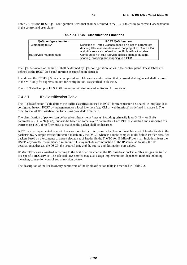
ETSI
ETSI TS 101 545-3 V1.1.1 (2012-05)43
Table 7.1 lists the RCST QoS configuration items that shall be required in the RCST to ensure to correct QoS behaviour in the control and user plane.
Table 7.1: RCST Classification Functions
QoS configuration Item RCST QoS function TC mapping to BA Definition of Traffic Classes based on a set of parameters
defining filter masks/criteria and mapping of a TC into a BA and HL service as defined in the IP classification table.
HL Service mapping table Configuration of HLS Service policies such as queuing, shaping, dropping and mapping to a PHB
The QoS behaviour of the RCST shall be defined by QoS configuration tables in the control plane. These tables are defined as the RCST QoS configuration as specified in clause 8.
In addition, the RCST QoS data is completed with LL services information that is provided at logon and shall be saved in the MIB only for supervision, not for configuration, as specified in clause 8.
The RCST shall support HLS PDU queues monitoring related to BA and HL services.
7.4.2.1 IP Classification Table
The IP Classification Table defines the traffic classification used in RCST for transmission on a satellite interface. It is configured in each RCST by management or a local interface (e.g. CLI or web interface) as defined in clause 8. The exact format of IP Classification Table is as provided in clause 8.
The classification of packets can be based on filter criteria / masks, including primarily layer 3 (IPv4 or IPv6) parameters (RFC 4594 [i.42], but also be based on some layer 2 parameters. Each PDU is classified and associated to a traffic class (TC). If no filter mask is matched the packet shall be discarded.
A TC may be implemented as a set of one or more traffic filter records. Each record matches a set of header fields in the packet/PDU. A simple traffic filter could match only the DSCP, whereas a more complex multi-field classifier classifies packets based on the contents of a pre-selected set of header fields. The TC for IP MicroFlows shall include at least the DSCP, anyhow the recommended minimum TC may include a combination of the IP source addresses, the IP destination addresses, the DSCP, the protocol type and the source and destination port values.
IP MicroFlows are classified according to the first filter matched in the IP Classification Table. This assigns the traffic to a specific HLS service. The selected HLS service may also assign implementation-dependent methods including metering, connection control and admission control.
The description of the IPClassEntry parameters of the IP classification table is described in Table 7.2.
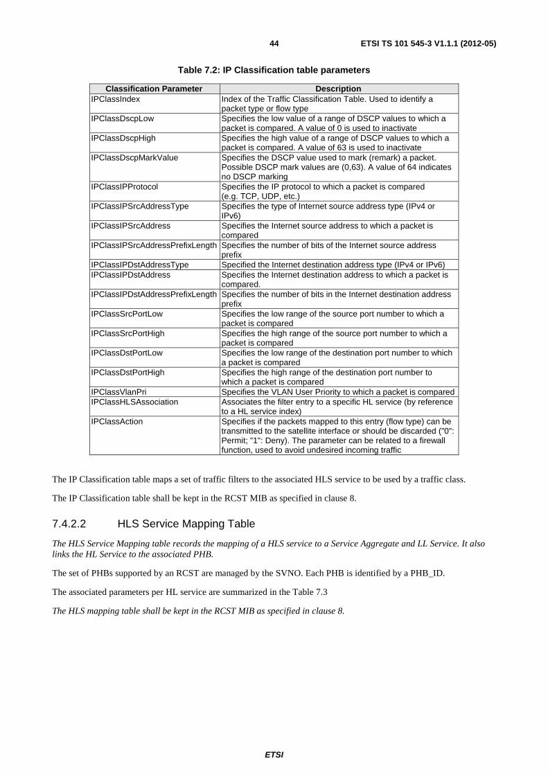
ETSI
ETSI TS 101 545-3 V1.1.1 (2012-05)44
Table 7.2: IP Classification table parameters
Classification Parameter Description IPClassIndex Index of the Traffic Classification Table. Used to identify a
packet type or flow type IPClassDscpLow Specifies the low value of a range of DSCP values to which a
packet is compared. A value of 0 is used to inactivate IPClassDscpHigh Specifies the high value of a range of DSCP values to which a
packet is compared. A value of 63 is used to inactivate IPClassDscpMarkValue Specifies the DSCP value used to mark (remark) a packet.
Possible DSCP mark values are (0,63). A value of 64 indicates no DSCP marking
IPClassIPProtocol Specifies the IP protocol to which a packet is compared (e.g. TCP, UDP, etc.)
IPClassIPSrcAddressType Specifies the type of Internet source address type (IPv4 or IPv6)
IPClassIPSrcAddress Specifies the Internet source address to which a packet is compared
IPClassIPSrcAddressPrefixLength Specifies the number of bits of the Internet source address prefix
IPClassIPDstAddressType Specified the Internet destination address type (IPv4 or IPv6) IPClassIPDstAddress Specifies the Internet destination address to which a packet is
compared. IPClassIPDstAddressPrefixLength Specifies the number of bits in the Internet destination address
prefix IPClassSrcPortLow Specifies the low range of the source port number to which a
packet is compared IPClassSrcPortHigh Specifies the high range of the source port number to which a
packet is compared IPClassDstPortLow Specifies the low range of the destination port number to which
a packet is compared IPClassDstPortHigh Specifies the high range of the destination port number to
which a packet is compared IPClassVlanPri Specifies the VLAN User Priority to which a packet is compared IPClassHLSAssociation Associates the filter entry to a specific HL service (by reference
to a HL service index) IPClassAction Specifies if the packets mapped to this entry (flow type) can be
transmitted to the satellite interface or should be discarded ("0": Permit; "1": Deny). The parameter can be related to a firewall function, used to avoid undesired incoming traffic
The IP Classification table maps a set of traffic filters to the associated HLS service to be used by a traffic class.
The IP Classification table shall be kept in the RCST MIB as specified in clause 8.
7.4.2.2 HLS Service Mapping Table
The HLS Service Mapping table records the mapping of a HLS service to a Service Aggregate and LL Service. It also links the HL Service to the associated PHB.
The set of PHBs supported by an RCST are managed by the SVNO. Each PHB is identified by a PHB_ID.
The associated parameters per HL service are summarized in the Table 7.3
The HLS mapping table shall be kept in the RCST MIB as specified in clause 8.
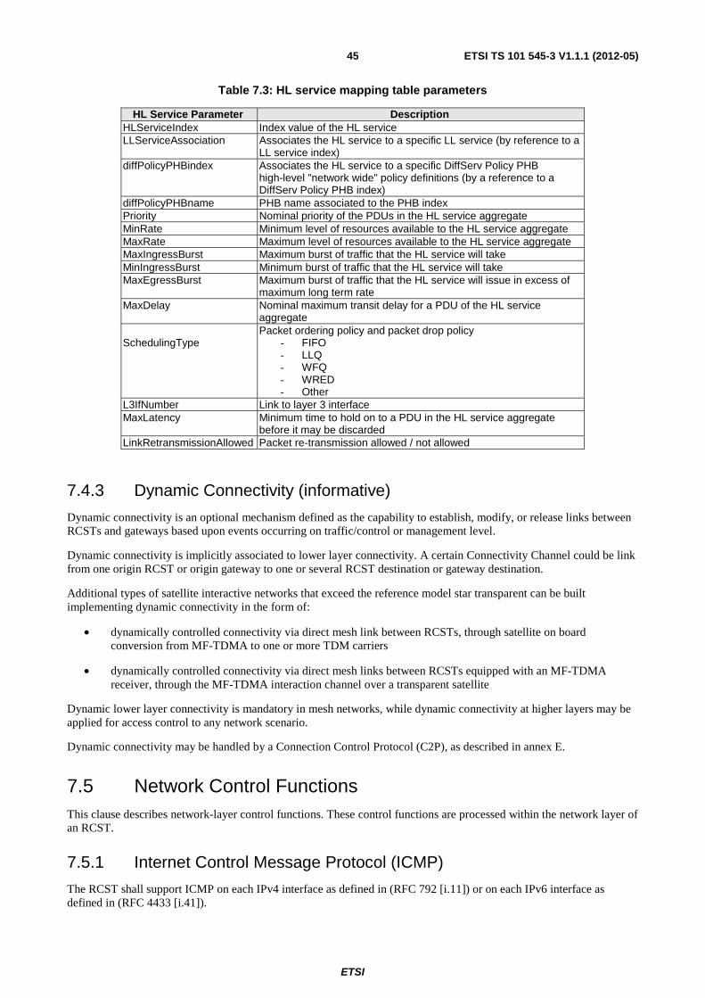
ETSI
ETSI TS 101 545-3 V1.1.1 (2012-05)45
Table 7.3: HL service mapping table parameters
HL Service Parameter Description HLServiceIndex Index value of the HL service LLServiceAssociation Associates the HL service to a specific LL service (by reference to a
LL service index) diffPolicyPHBindex Associates the HL service to a specific DiffServ Policy PHB
high-level "network wide" policy definitions (by a reference to a DiffServ Policy PHB index)
diffPolicyPHBname PHB name associated to the PHB index Priority Nominal priority of the PDUs in the HL service aggregate MinRate Minimum level of resources available to the HL service aggregate MaxRate Maximum level of resources available to the HL service aggregate MaxIngressBurst Maximum burst of traffic that the HL service will take MinIngressBurst Minimum burst of traffic that the HL service will take MaxEgressBurst Maximum burst of traffic that the HL service will issue in excess of
maximum long term rate MaxDelay Nominal maximum transit delay for a PDU of the HL service
aggregate SchedulingType
Packet ordering policy and packet drop policy - FIFO - LLQ - WFQ - WRED - Other
L3IfNumber Link to layer 3 interface MaxLatency Minimum time to hold on to a PDU in the HL service aggregate
before it may be discarded LinkRetransmissionAllowed Packet re-transmission allowed / not allowed
7.4.3 Dynamic Connectivity (informative)
Dynamic connectivity is an optional mechanism defined as the capability to establish, modify, or release links between RCSTs and gateways based upon events occurring on traffic/control or management level.
Dynamic connectivity is implicitly associated to lower layer connectivity. A certain Connectivity Channel could be link from one origin RCST or origin gateway to one or several RCST destination or gateway destination.
Additional types of satellite interactive networks that exceed the reference model star transparent can be built implementing dynamic connectivity in the form of:
• dynamically controlled connectivity via direct mesh link between RCSTs, through satellite on board conversion from MF-TDMA to one or more TDM carriers
• dynamically controlled connectivity via direct mesh links between RCSTs equipped with an MF-TDMA receiver, through the MF-TDMA interaction channel over a transparent satellite
Dynamic lower layer connectivity is mandatory in mesh networks, while dynamic connectivity at higher layers may be applied for access control to any network scenario.
Dynamic connectivity may be handled by a Connection Control Protocol (C2P), as described in annex E.
7.5 Network Control Functions This clause describes network-layer control functions. These control functions are processed within the network layer of an RCST.
7.5.1 Internet Control Message Protocol (ICMP)
The RCST shall support ICMP on each IPv4 interface as defined in (RFC 792 [i.11]) or on each IPv6 interface as defined in (RFC 4433 [i.41]).
ETSI
ETSI TS 101 545-3 V1.1.1 (2012-05)46
The RCST shall respond to an ICMP-Echo request received via the satellite interface to any of its configured IP Interfaces when sent using the SVN-MAC label for the IP Interface.
An RCST shall respond to an ICMP-Echo request received via the satellite interface to the broadcast subnet address of IP network for which it is configured, when this is received using the SVN-MAC identifier corresponding to the IP Interface.
An RCST shall not respond to an ICMP-Echo request sent to the management IP address via a LAN Interface (unless this VRF Group is explicitly made available on a dedicated LAN interface).
An RCST should respond to an ICMP-Echo request sent to any assigned traffic IP address via any LAN Interface.
An RCST shall not respond to any ICMP-Echo request sent with an IP multicast destination address.
7.5.2 Neighbour Discovery (ND)
An RCST that supports IPv6 shall support ND as a configurable option on each active LAN interface. Use of ND on the satellite air interface is not specified in the present document.
7.5.3 Dynamic Host Configuration
The Dynamic Host Configuration Protocol (DHCP) is defined in (RFC 2131 [i.15]). The DHCP automates network-parameter assignment to network devices connected to a LAN interface from one or more DHCP servers. DHCP makes it easy to add new network devices to a network.
An RCST may support DHCP as a configurable option on each LAN interface. This may be a DHCP client interface.
An RCST may support a DHCP server that provides dynamic, automatic or static leases of addresses using an active LAN interface. An RCST that provides an IPv4 DHCP server may support DHCP-Relay as a configurable option on each active LAN interface.
The extensions of DHCP for IPv6 (DHCPv6) are specified in (RFC 3315 [i.33]). An RCST that supports IPv6 shall support DHCPv6 as a configurable option on each active LAN interface. This may be a client interface, or may be a server providing dynamic, automatic or static leases of addresses.
An RCST that supports an IPv6 DHCP server may support DHCP-Relay as a configurable option on an active LAN interface.
7.6 Extensions for Adapting the PDU As introduced in the System specification [2], the RCST shall support a forward link using the Generic Stream Encapsulation (GSE) [4] protocol exclusively, including for transport of signalling, except for the migration scenarios already stated in the System specification [2]. The RCST shall also comply to GSE additional extensions defined in (RFC 4326 [i.40]) and (RFC 5163 [i.48]). The RCST Return Link shall support MF-TDMA link using the Return Link Encapsulation (RLE) [3].
An RCST may receive a GSE PDU that includes one or more extensions headers that are added by a remote HLS module to a PDU payload.
The PDU queued in the HLS PDU Queue may include one or more extensions headers that are added by an HLS module to a PDU payload. These extensions headers are identified at the HLS level by a 16 bit identifier encoded according to [4], and formatted as defined in section 5 of (RFC 4326 [i.40]). These extension headers are communicated along with the PDU payload to the remote HLS entity at the Gateway, NCC, or RCST. These headers shall be processed according to the reception rules for GSE.
ETSI
ETSI TS 101 545-3 V1.1.1 (2012-05)47
Extension headers correspond to one of two types:
• An Optional Extension Header has a pre-defined length that is encoded in the extension field. An Optional Extension Header does not modify the format or encoding of the enclosed PDU (i.e. it can only add a tag or additional information to a PDU). If the header codepoint is not recognised at the receiver, the optional information is silently discarded, and the remainder of the PDU is processed (including any remaining extension headers). Sender modules that introduce optional headers may also include a probing mechanism to ensure that the remote endpoint is able to process the header they provide.
• Each Mandatory Extension Header has a length that is not necessarily communicated in the extension field. No limit is placed on the maximum length of a Mandatory Extension Header. A Mandatory Extension Header can modify the format or encoding of the enclosed PDU (e.g. to perform encryption and/or compression). The term "mandatory" refers to the receiver processing action, and not to the required support for the option. If the header codepoint is not recognised at the receiver, the PDU is silently discarded. Sender modules that introduce mandatory headers are advised to include a probing mechanism to ensure that the remote endpoint is able to process the header they provide.
Using this method, several PDU extension headers can be chained in series. The sender at the RCS lower layers may also add extension headers that enhance the physical layer (such as headers to support packet FEC). These extension headers are also removed after processing by the corresponding lower layer receiver, before an encapsulated PDU is passed to the higher layers. (RFC 5163 [i.48]) provides guidance on the ordering of extension headers when multiple extension headers are used.
Reception of an encapsulated PDU with an unknown protocol feature shall result in discard of the enclosed PDU.
7.6.1 Header Compression
Operation of header compression is not specified in the current version of the present document.
7.6.2 Bulk Compression
While bulk compression is intended to be transparent, that is the output data stream is meant to be identical to the input data stream, there are also loosely compression methods that rely on transcoding to modify the data. This approach generally requires knowledge and is described further in the section on transcoding.
Operation of bulk compression is not specified in the current version of the present document.
8 Management signalling This clause and subclauses are in the present document provided as a recommendation for guiding in aligning implementations of M and C, aiming at a future evolution towards normative status.
The following recommendations are intended to be partly superseded and partly supplemented by an implementation dependent RCST MIB ASN.1 specification and an implementation dependent RCST configuration file specification. The combination of the present document and these specifications, assumed provided for an implementation, are intended to be the basis for bilateral interoperability in the management plane over the satellite interface.
8.1 Management reference architecture This clause describes the network management functionality associated with DVB-RCS2 network. The purpose is to establish the basic framework for RCS network to be seen as part of the TMN model of telecom network management to help the operators to configure and manage the RCS network in an easy way. For this reason, the main management interfaces, management protocols, information and syntax needs to be identified.
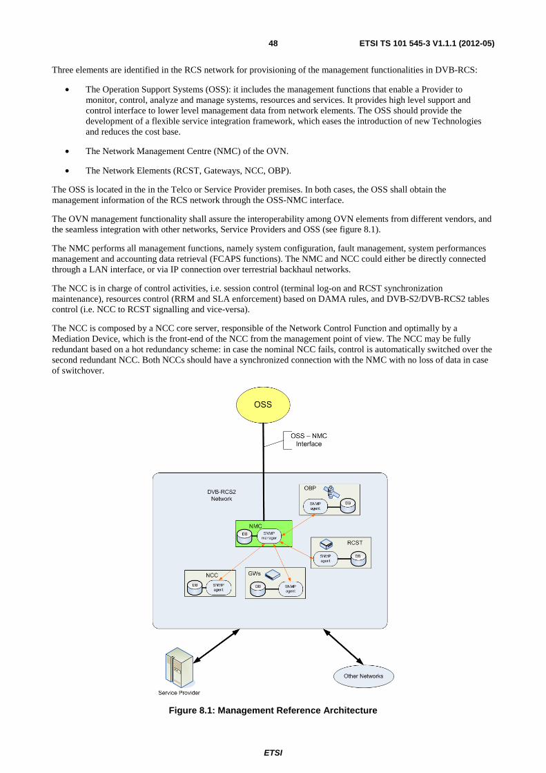
ETSI
ETSI TS 101 545-3 V1.1.1 (2012-05)48
Three elements are identified in the RCS network for provisioning of the management functionalities in DVB-RCS:
• The Operation Support Systems (OSS): it includes the management functions that enable a Provider to monitor, control, analyze and manage systems, resources and services. It provides high level support and control interface to lower level management data from network elements. The OSS should provide the development of a flexible service integration framework, which eases the introduction of new Technologies and reduces the cost base.
• The Network Management Centre (NMC) of the OVN.
• The Network Elements (RCST, Gateways, NCC, OBP).
The OSS is located in the in the Telco or Service Provider premises. In both cases, the OSS shall obtain the management information of the RCS network through the OSS-NMC interface.
The OVN management functionality shall assure the interoperability among OVN elements from different vendors, and the seamless integration with other networks, Service Providers and OSS (see figure 8.1).
The NMC performs all management functions, namely system configuration, fault management, system performances management and accounting data retrieval (FCAPS functions). The NMC and NCC could either be directly connected through a LAN interface, or via IP connection over terrestrial backhaul networks.
The NCC is in charge of control activities, i.e. session control (terminal log-on and RCST synchronization maintenance), resources control (RRM and SLA enforcement) based on DAMA rules, and DVB-S2/DVB-RCS2 tables control (i.e. NCC to RCST signalling and vice-versa).
The NCC is composed by a NCC core server, responsible of the Network Control Function and optimally by a Mediation Device, which is the front-end of the NCC from the management point of view. The NCC may be fully redundant based on a hot redundancy scheme: in case the nominal NCC fails, control is automatically switched over the second redundant NCC. Both NCCs should have a synchronized connection with the NMC with no loss of data in case of switchover.
Figure 8.1: Management Reference Architecture
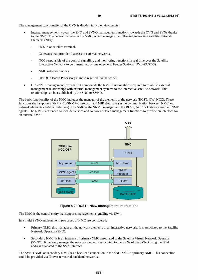
ETSI
ETSI TS 101 545-3 V1.1.1 (2012-05)49
The management functionality of the OVN is divided in two environments:
• Internal management: covers the SNO and SVNO management functions towards the OVN and SVNs thanks to the NMC. The central manager is the NMC, which manages the following interactive satellite Network Elements (NEs):
- RCSTs or satellite terminal.
- Gateways that provide IP access to external networks.
- NCC responsible of the control signalling and monitoring functions in real time over the Satellite Interactive Network to be transmitted by one or several Feeder Stations (DVB-RCS2-S).
- NMC network devices.
- OBP (On Board Processor) in mesh regenerative networks.
• OSS-NMC management (external): it compounds the NMC functionalities required to establish external management relationships with external management systems to the interactive satellite network. This relationship can be established by the SNO or SVNO.
The basic functionality of the NMC includes the manager of the elements of the network (RCST, GW, NCC). These functions shall support a SNMPv2c/SNMPv3 protocol and MIB data base (in the communication between NMC and network elements - Internal interface). The NMC is the SNMP manager and the RCST, NCC or Gateway are the SNMP agents. The NMC is extended to include Service and Network related management functions to provide an interface for an external OSS.
Figure 8.2: RCST - NMC management interactions
The NMC is the central entity that supports management signalling via IPv4.
In a multi SVNO environment, two types of NMC are considered:
• Primary NMC: this manages all the network elements of an interactive network. It is associated to the Satellite Network Operator (SNO).
• Secondary NMC: it is an instance of primary NMC associated to the Satellite Virtual Network Operator (SVNO). It can only manage the network elements associated to the SVNs of the SVNO using the IPv4 address allocated to the SVN interface.
The SVNO NMC or secondary NMC has a back-end connection to the SNO NMC or primary NMC. This connection could be provided via IP over terrestrial backhaul networks.
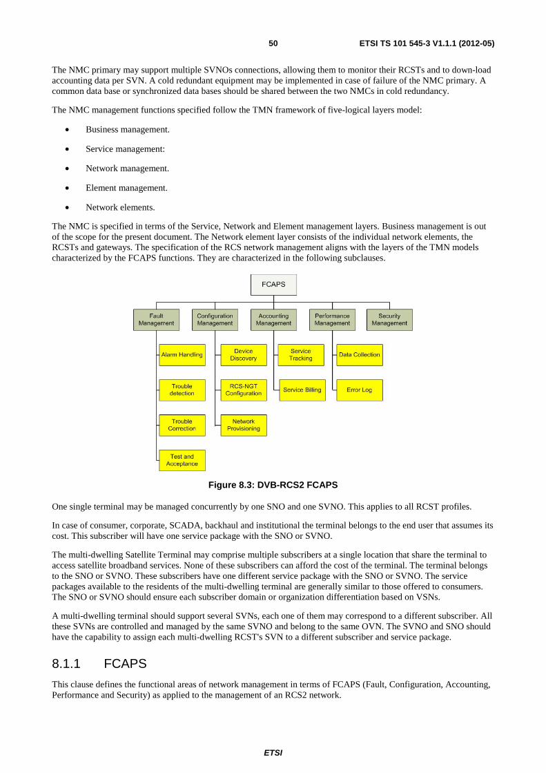
ETSI
ETSI TS 101 545-3 V1.1.1 (2012-05)50
The NMC primary may support multiple SVNOs connections, allowing them to monitor their RCSTs and to down-load accounting data per SVN. A cold redundant equipment may be implemented in case of failure of the NMC primary. A common data base or synchronized data bases should be shared between the two NMCs in cold redundancy.
The NMC management functions specified follow the TMN framework of five-logical layers model:
• Business management.
• Service management:
• Network management.
• Element management.
• Network elements.
The NMC is specified in terms of the Service, Network and Element management layers. Business management is out of the scope for the present document. The Network element layer consists of the individual network elements, the RCSTs and gateways. The specification of the RCS network management aligns with the layers of the TMN models characterized by the FCAPS functions. They are characterized in the following subclauses.
Figure 8.3: DVB-RCS2 FCAPS
One single terminal may be managed concurrently by one SNO and one SVNO. This applies to all RCST profiles.
In case of consumer, corporate, SCADA, backhaul and institutional the terminal belongs to the end user that assumes its cost. This subscriber will have one service package with the SNO or SVNO.
The multi-dwelling Satellite Terminal may comprise multiple subscribers at a single location that share the terminal to access satellite broadband services. None of these subscribers can afford the cost of the terminal. The terminal belongs to the SNO or SVNO. These subscribers have one different service package with the SNO or SVNO. The service packages available to the residents of the multi-dwelling terminal are generally similar to those offered to consumers. The SNO or SVNO should ensure each subscriber domain or organization differentiation based on VSNs.
A multi-dwelling terminal should support several SVNs, each one of them may correspond to a different subscriber. All these SVNs are controlled and managed by the same SVNO and belong to the same OVN. The SVNO and SNO should have the capability to assign each multi-dwelling RCST's SVN to a different subscriber and service package.
8.1.1 FCAPS
This clause defines the functional areas of network management in terms of FCAPS (Fault, Configuration, Accounting, Performance and Security) as applied to the management of an RCS2 network.
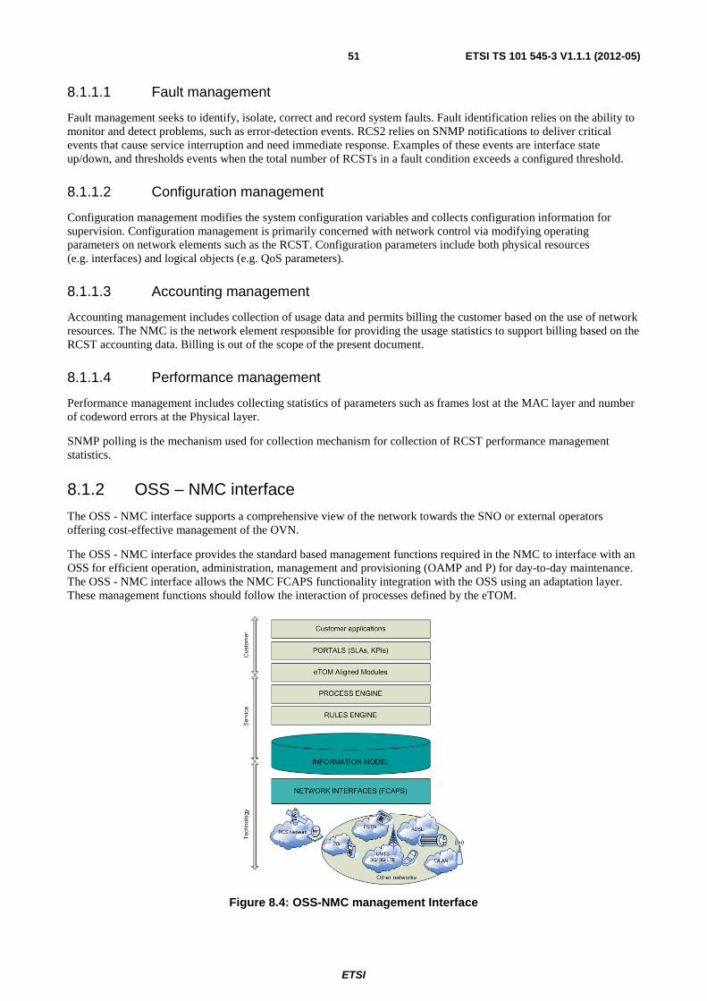
ETSI
ETSI TS 101 545-3 V1.1.1 (2012-05)51
8.1.1.1 Fault management
Fault management seeks to identify, isolate, correct and record system faults. Fault identification relies on the ability to monitor and detect problems, such as error-detection events. RCS2 relies on SNMP notifications to deliver critical events that cause service interruption and need immediate response. Examples of these events are interface state up/down, and thresholds events when the total number of RCSTs in a fault condition exceeds a configured threshold.
8.1.1.2 Configuration management
Configuration management modifies the system configuration variables and collects configuration information for supervision. Configuration management is primarily concerned with network control via modifying operating parameters on network elements such as the RCST. Configuration parameters include both physical resources (e.g. interfaces) and logical objects (e.g. QoS parameters).
8.1.1.3 Accounting management
Accounting management includes collection of usage data and permits billing the customer based on the use of network resources. The NMC is the network element responsible for providing the usage statistics to support billing based on the RCST accounting data. Billing is out of the scope of the present document.
8.1.1.4 Performance management
Performance management includes collecting statistics of parameters such as frames lost at the MAC layer and number of codeword errors at the Physical layer.
SNMP polling is the mechanism used for collection mechanism for collection of RCST performance management statistics.
8.1.2 OSS – NMC interface
The OSS - NMC interface supports a comprehensive view of the network towards the SNO or external operators offering cost-effective management of the OVN.
The OSS - NMC interface provides the standard based management functions required in the NMC to interface with an OSS for efficient operation, administration, management and provisioning (OAMP and P) for day-to-day maintenance. The OSS - NMC interface allows the NMC FCAPS functionality integration with the OSS using an adaptation layer. These management functions should follow the interaction of processes defined by the eTOM.
Figure 8.4: OSS-NMC management Interface
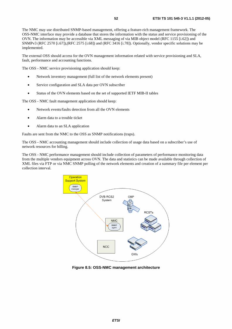
ETSI
ETSI TS 101 545-3 V1.1.1 (2012-05)52
The NMC may use distributed SNMP-based management, offering a feature-rich management framework. The OSS-NMC interface may provide a database that stores the information with the status and service provisioning of the OVN. The information may be accessible via XML messaging of via MIB object model (RFC 1155 [i.62]) and SNMPv3 (RFC 2570 [i.67]),(RFC 2575 [i.68]) and (RFC 3416 [i.78]). Optionally, vendor specific solutions may be implemented.
The external OSS should access for the OVN management information related with service provisioning and SLA, fault, performance and accounting functions.
The OSS - NMC service provisioning application should keep:
• Network inventory management (full list of the network elements present)
• Service configuration and SLA data per OVN subscriber
• Status of the OVN elements based on the set of supported IETF MIB-II tables
The OSS - NMC fault management application should keep:
• Network events/faults detection from all the OVN elements
• Alarm data to a trouble ticket
• Alarm data to an SLA application
Faults are sent from the NMC to the OSS as SNMP notifications (traps).
The OSS - NMC accounting management should include collection of usage data based on a subscriber’s use of network resources for billing.
The OSS - NMC performance management should include collection of parameters of performance monitoring data from the multiple vendors equipment across OVN. The data and statistics can be made available through collection of XML files via FTP or via NMC SNMP polling of the network elements and creation of a summary file per element per collection interval.
Figure 8.5: OSS-NMC management architecture
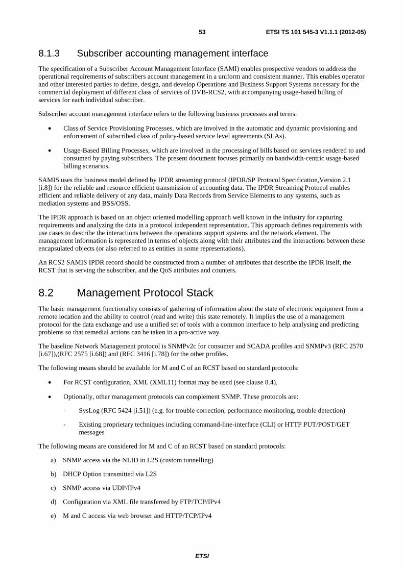
ETSI
ETSI TS 101 545-3 V1.1.1 (2012-05)53
8.1.3 Subscriber accounting management interface
The specification of a Subscriber Account Management Interface (SAMI) enables prospective vendors to address the operational requirements of subscribers account management in a uniform and consistent manner. This enables operator and other interested parties to define, design, and develop Operations and Business Support Systems necessary for the commercial deployment of different class of services of DVB-RCS2, with accompanying usage-based billing of services for each individual subscriber.
Subscriber account management interface refers to the following business processes and terms:
• Class of Service Provisioning Processes, which are involved in the automatic and dynamic provisioning and enforcement of subscribed class of policy-based service level agreements (SLAs).
• Usage-Based Billing Processes, which are involved in the processing of bills based on services rendered to and consumed by paying subscribers. The present document focuses primarily on bandwidth-centric usage-based billing scenarios.
SAMIS uses the business model defined by IPDR streaming protocol (IPDR/SP Protocol Specification,Version 2.1 [i.8]) for the reliable and resource efficient transmission of accounting data. The IPDR Streaming Protocol enables efficient and reliable delivery of any data, mainly Data Records from Service Elements to any systems, such as mediation systems and BSS/OSS.
The IPDR approach is based on an object oriented modelling approach well known in the industry for capturing requirements and analyzing the data in a protocol independent representation. This approach defines requirements with use cases to describe the interactions between the operations support systems and the network element. The management information is represented in terms of objects along with their attributes and the interactions between these encapsulated objects (or also referred to as entities in some representations).
An RCS2 SAMIS IPDR record should be constructed from a number of attributes that describe the IPDR itself, the RCST that is serving the subscriber, and the QoS attributes and counters.
8.2 Management Protocol Stack The basic management functionality consists of gathering of information about the state of electronic equipment from a remote location and the ability to control (read and write) this state remotely. It implies the use of a management protocol for the data exchange and use a unified set of tools with a common interface to help analysing and predicting problems so that remedial actions can be taken in a pro-active way.
The baseline Network Management protocol is SNMPv2c for consumer and SCADA profiles and SNMPv3 (RFC 2570 [i.67]),(RFC 2575 [i.68]) and (RFC 3416 [i.78]) for the other profiles.
The following means should be available for M and C of an RCST based on standard protocols:
• For RCST configuration, XML (XML11) format may be used (see clause 8.4).
• Optionally, other management protocols can complement SNMP. These protocols are:
- SysLog (RFC 5424 [i.51]) (e.g. for trouble correction, performance monitoring, trouble detection)
- Existing proprietary techniques including command-line-interface (CLI) or HTTP PUT/POST/GET messages
The following means are considered for M and C of an RCST based on standard protocols:
a) SNMP access via the NLID in L2S (custom tunnelling)
b) DHCP Option transmitted via L2S
c) SNMP access via UDP/IPv4
d) Configuration via XML file transferred by FTP/TCP/IPv4
e) M and C access via web browser and HTTP/TCP/IPv4
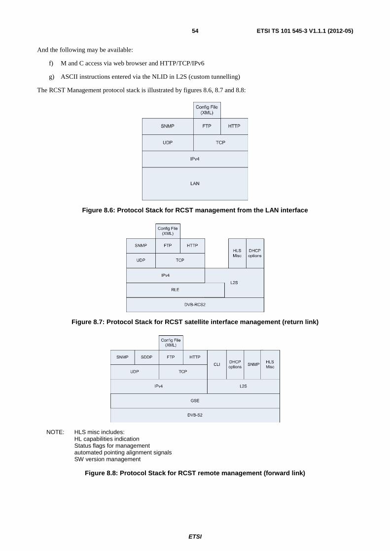
ETSI
ETSI TS 101 545-3 V1.1.1 (2012-05)54
And the following may be available:
f) M and C access via web browser and HTTP/TCP/IPv6
g) ASCII instructions entered via the NLID in L2S (custom tunnelling)
The RCST Management protocol stack is illustrated by figures 8.6, 8.7 and 8.8:
Figure 8.6: Protocol Stack for RCST management from the LAN interface
Figure 8.7: Protocol Stack for RCST satellite interface management (return link)
NOTE: HLS misc includes: HL capabilities indication Status flags for management automated pointing alignment signals SW version management
Figure 8.8: Protocol Stack for RCST remote management (forward link)
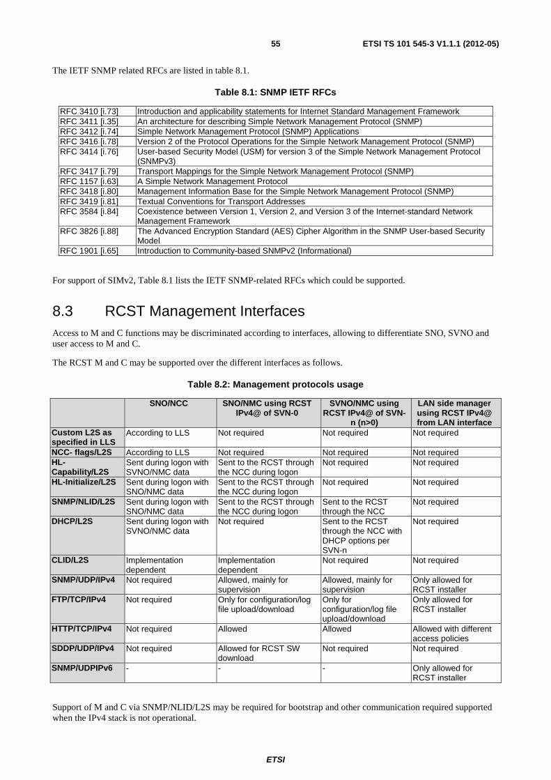
ETSI
ETSI TS 101 545-3 V1.1.1 (2012-05)55
The IETF SNMP related RFCs are listed in table 8.1.
Table 8.1: SNMP IETF RFCs
RFC 3410 [i.73] Introduction and applicability statements for Internet Standard Management Framework RFC 3411 [i.35] An architecture for describing Simple Network Management Protocol (SNMP) RFC 3412 [i.74] Simple Network Management Protocol (SNMP) Applications RFC 3416 [i.78] Version 2 of the Protocol Operations for the Simple Network Management Protocol (SNMP) RFC 3414 [i.76] User-based Security Model (USM) for version 3 of the Simple Network Management Protocol
(SNMPv3) RFC 3417 [i.79] Transport Mappings for the Simple Network Management Protocol (SNMP) RFC 1157 [i.63] A Simple Network Management Protocol RFC 3418 [i.80] Management Information Base for the Simple Network Management Protocol (SNMP) RFC 3419 [i.81] Textual Conventions for Transport Addresses RFC 3584 [i.84] Coexistence between Version 1, Version 2, and Version 3 of the Internet-standard Network
Management Framework RFC 3826 [i.88] The Advanced Encryption Standard (AES) Cipher Algorithm in the SNMP User-based Security
Model RFC 1901 [i.65] Introduction to Community-based SNMPv2 (Informational)
For support of SIMv2, Table 8.1 lists the IETF SNMP-related RFCs which could be supported.
8.3 RCST Management Interfaces Access to M and C functions may be discriminated according to interfaces, allowing to differentiate SNO, SVNO and user access to M and C.
The RCST M and C may be supported over the different interfaces as follows.
Table 8.2: Management protocols usage
SNO/NCC SNO/NMC using RCST IPv4@ of SVN-0
SVNO/NMC using RCST IPv4@ of SVN-
n (n>0)
LAN side manager using RCST IPv4@ from LAN interface
Custom L2S as specified in LLS
According to LLS Not required Not required Not required
NCC- flags/L2S According to LLS Not required Not required Not required HL-Capability/L2S
Sent during logon with SVNO/NMC data
Sent to the RCST through the NCC during logon
Not required Not required
HL-Initialize/L2S Sent during logon with SNO/NMC data
Sent to the RCST through the NCC during logon
Not required Not required
SNMP/NLID/L2S Sent during logon with SNO/NMC data
Sent to the RCST through the NCC during logon
Sent to the RCST through the NCC
Not required
DHCP/L2S Sent during logon with SVNO/NMC data
Not required Sent to the RCST through the NCC with DHCP options per SVN-n
Not required
CLID/L2S Implementation dependent
Implementation dependent
Not required Not required
SNMP/UDP/IPv4 Not required Allowed, mainly for supervision
Allowed, mainly for supervision
Only allowed for RCST installer
FTP/TCP/IPv4 Not required Only for configuration/log file upload/download
Only for configuration/log file upload/download
Only allowed for RCST installer
HTTP/TCP/IPv4 Not required Allowed Allowed Allowed with different access policies
SDDP/UDP/IPv4 Not required Allowed for RCST SW download
Not required Not required
SNMP/UDPIPv6 - - - Only allowed for RCST installer
Support of M and C via SNMP/NLID/L2S may be required for bootstrap and other communication required supported when the IPv4 stack is not operational.
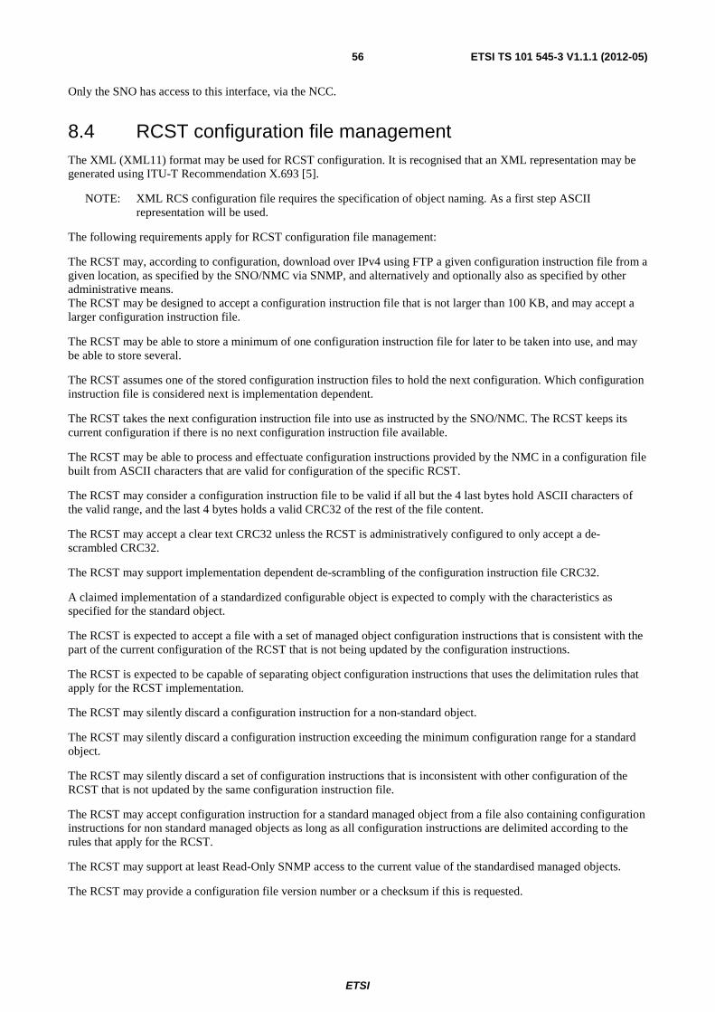
ETSI
ETSI TS 101 545-3 V1.1.1 (2012-05)56
Only the SNO has access to this interface, via the NCC.
8.4 RCST configuration file management The XML (XML11) format may be used for RCST configuration. It is recognised that an XML representation may be generated using ITU-T Recommendation X.693 [5].
NOTE: XML RCS configuration file requires the specification of object naming. As a first step ASCII representation will be used.
The following requirements apply for RCST configuration file management:
The RCST may, according to configuration, download over IPv4 using FTP a given configuration instruction file from a given location, as specified by the SNO/NMC via SNMP, and alternatively and optionally also as specified by other administrative means. The RCST may be designed to accept a configuration instruction file that is not larger than 100 KB, and may accept a larger configuration instruction file.
The RCST may be able to store a minimum of one configuration instruction file for later to be taken into use, and may be able to store several.
The RCST assumes one of the stored configuration instruction files to hold the next configuration. Which configuration instruction file is considered next is implementation dependent.
The RCST takes the next configuration instruction file into use as instructed by the SNO/NMC. The RCST keeps its current configuration if there is no next configuration instruction file available.
The RCST may be able to process and effectuate configuration instructions provided by the NMC in a configuration file built from ASCII characters that are valid for configuration of the specific RCST.
The RCST may consider a configuration instruction file to be valid if all but the 4 last bytes hold ASCII characters of the valid range, and the last 4 bytes holds a valid CRC32 of the rest of the file content.
The RCST may accept a clear text CRC32 unless the RCST is administratively configured to only accept a de-scrambled CRC32.
The RCST may support implementation dependent de-scrambling of the configuration instruction file CRC32.
A claimed implementation of a standardized configurable object is expected to comply with the characteristics as specified for the standard object.
The RCST is expected to accept a file with a set of managed object configuration instructions that is consistent with the part of the current configuration of the RCST that is not being updated by the configuration instructions.
The RCST is expected to be capable of separating object configuration instructions that uses the delimitation rules that apply for the RCST implementation.
The RCST may silently discard a configuration instruction for a non-standard object.
The RCST may silently discard a configuration instruction exceeding the minimum configuration range for a standard object.
The RCST may silently discard a set of configuration instructions that is inconsistent with other configuration of the RCST that is not updated by the same configuration instruction file.
The RCST may accept configuration instruction for a standard managed object from a file also containing configuration instructions for non standard managed objects as long as all configuration instructions are delimited according to the rules that apply for the RCST.
The RCST may support at least Read-Only SNMP access to the current value of the standardised managed objects.
The RCST may provide a configuration file version number or a checksum if this is requested.
ETSI
ETSI TS 101 545-3 V1.1.1 (2012-05)57
The version indicator of the configuration file is a Display String (RFC 1213 [i.64]). The file version will be contained in the file and its calculation is vendor specific. The following data objects may be used in the configuration update procedure:
• IP address of the TFTP/FTP server and path where the configuration file is located.
• Command to start the configuration download.
• Parameter to store the version of the downloaded configuration file.
• Command to activate the new configuration file.
• Parameter to store the version of the active configuration file.
The RCST configuration file parameters follow the same syntax as the parameters configured in the RCST MIB.
The configuration file remote download proceeds as follows:
1) Configuration update process may start anytime once the RCST has acquired the forward link and has performed a first log on.
2) The SNO will configure the FTP server IP address in the RCST.
3) The SNO will send a command for starting the download of the configuration file.
4) The RCST uses FTP and the above information to download the configuration file. Once downloaded, it validates the configuration file and checks the file version. Upon a successful validation and check, the RCST may update the parameter storing the last ‘downloaded’ configuration with the version of the file that was just downloaded.
5) The SNO will execute a command to activate the new configuration file at the desired time of activation (immediately following the download command or at a later time). In some RCST implementation, it may be required for the RCST to reboot in order to take into account the new configuration file (vendor specific). When the configuration file is activated, the RCST may update the object indicating the active configuration version of the activated configuration.
Full or delta configuration of common elements defined by the present document may be supported.
If there is a change done to the RCST configuration in advance of the activation of the file, this may superseded by the newly activated Configuration File.
8.5 RCST Software Delivery Download Management When the RCST boots, it will first verify that the installed SW image is appropriate and will only then join the OVN (see the definition of the protocol for software upgrade in annex C).
The transition between software download and joining the OVN is vendor specific (a vendor may choose to perform a re-boot to achieve this).
8.5.1 RCST Software Delivery Download parameters
The basic parameters to perform the RCST software update are:
• Minimum SW version to operate in the System. This information is obtained from TIM-b through the Lowest Software Version descriptor. Lowest Software versions to operate in the interactive system are classified according to vendor OUI.
• Current software version executing at the terminal. The version is indicated to the NCC in the Logon burst (see [3]).
• Alternate software version (not the default for execution) stored in the RCST.
ETSI
ETSI TS 101 545-3 V1.1.1 (2012-05)58
• Reboot command parameter. This variable may be used to force an RCST to reboot:
1) idle
2) normal = normal reboot (from current software load)
3) alternate = reboot from alternate load (swap to alternate load before reboot)
• The IP information for downloading a software version that is being broadcasted/multicasted. This consists of the multicast IPv4 address and the UDP port that can be used to perform the Software download.
• A flag parameter to indicate to the RCST whether or not to ignore or not the SW version notified in TIM-b.
The RCST software update parameters may be kept in the RCST MIB and accessed by the SNO.
8.5.2 RCST Software Delivery Download procedure
The IP information to perform the SW download is taken from the Lowest Software Version descriptor that can be included in both TIM-b and TIM-u tables. Once RCST has acquired the forward channel, the RCST decodes this descriptor when included in the TIM-b, to execute a Software Upgrade procedure if the SW version of the RCST is lower that the indicated lowest software version broadcasted/multicasted, unless it has been configured to ignore broadcasted/multicasted Software updates.
The RCST does not need to download a new Software in case the lowest SW version indicated or a later version is already available.
At any moment, the SNO may force a Software change procedure on the RCST, using the Lowest Software Version descriptor included in the TIM-u. This applies for an upgrade or a downgrade, upon SNO discretion. In this case, the RCST may interrupt an ongoing software download operation.
The RCST may calculate an implementation dependent checksum of the downloaded Software image.
The software version field of the Logon burst is of size 8-bits, this cannot therefore be used to represent the exact software version. The value assigned in the CSC for a given software image is a vendor-specific. Vendors must publish a mapping table that relates the value reported in the CSC burst to the actual software version. The NCC should use the MAC address (in the CSC) to differentiate the reported software version for a specific vendor. In this way it may discriminate between two reported values from different vendors.
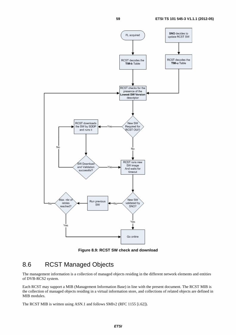
ETSI
ETSI TS 101 545-3 V1.1.1 (2012-05)59
Figure 8.9: RCST SW check and download
8.6 RCST Managed Objects The management information is a collection of managed objects residing in the different network elements and entities of DVB-RCS2 system.
Each RCST may support a MIB (Management Information Base) in line with the present document. The RCST MIB is the collection of managed objects residing in a virtual information store, and collections of related objects are defined in MIB modules.
The RCST MIB is written using ASN.1 and follows SMIv2 (RFC 1155 [i.62]).
ETSI
ETSI TS 101 545-3 V1.1.1 (2012-05)60
Each managed object is expected to be specified with:
• the function applicable for the managed object
• impact of the managed object with respect to the applicable function
• parameter value type
• minimum value range for configuration
• default value
• persistence of configured value across reboot
• persistence of configured value across change of SNO domain
• persistence of configured value across an ordered reset to system faults (if this is applicable)
• mandatory or optional support over SNMP for interfacing a standard SNMP/IP based manager
• mandatory or optional support via ASCII based configuration instructions provided on file via FTP
• differences between SVNO and SNO management
• mandatory or optional support via HTTP for interfacing a standard web browser
The managed objects for support of RCST management are identified in the following clauses. Several sources are used to collect existing managed objects:
• MIB objects from RFC 5728 [i.55] located under the iso.org.dod.internet.mgnt.mib-2 branch. IANA has assigned transmission number 239
• MIB objects from MIB-II, sysObjectID from the system group of the mib-2 is used to provide an OID pointer to the vendor-specific RCS2 MIB
• Additional MIB modules which includes RCS2 vendor specific management information
The configuration of managed objects in the RCST may be supported either by SNMPv2c / SNMPv3 protocol and by configuration file. For most objects the latter is applicable.
The RCST may use the following tables to provide the desired SNMP Access:
• snmpCommunityTable (RFC 3584 [i.84]) for SNMP community configuration
• snmpTargetAddrTable (RFC 3413 [i.75])
• vacmAccessTable (RFC 3415 [i.77]): view access table configuration
The RCST may implement the MIB requirements in accordance to the present document regardless of the status of the object in the referenced source (e.g. deprecated or optional).
If not required by the present document, additional objects are optional.
The SNMP messages supported by the RCST are given in table 8.1.
Table 8.3: SNMP messages
Messages Interface get-request [MIB variable] forward
get-next-request [MIB variable] forward get-response [MIB variable,value] return
set-request[ack flag] forward trap[MIB variable value, value] return
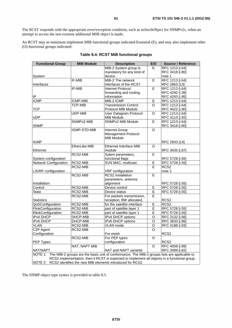
ETSI
ETSI TS 101 545-3 V1.1.1 (2012-05)61
The RCST responds with the appropriate error/exception condition, such as noSuchObject for SNMPv2c, when an attempt to access the non existent additional MIB object is made.
An RCST may as minimum implement MIB functional groups indicated Essential (E), and may also implement other (O) functional groups indicated:
Table 8.4: RCST MIB functional groups
Functional Group MIB Module Description E/O Source / Reference
System
MIB-2 System group is mandatory for any kind of device
E RFC 1213 [i.64] RFC 3418 [i.80] note 1
Interfaces IF-MIB MIB-2 The network
interfaces of the RCST E RFC 1213 [i.64]
RFC 2863 [13]
IP
IP-MIB Internet Protocol forwarding and routing information
E RFC 1213 [i.64] RFC 4292 [i.39] RFC 4293 [i.95]
ICMP ICMP-MIB MIB-2 ICMP E RFC 1213 [i.64]
TCP TCP-MIB Transmission Control
Protocol MIB Module O RFC 1213 [i.64]
RFC 4022 [i.90]
UDP UDP-MIB User Datagram Protocol
MIB Module O RFC 1213 [i.64]
RFC 4113 [i.92]
SNMP SNMPv2-MIB SNMPv2 MIB Module
E RFC 1213 [i.64]
RFC 3418 [i.80]
IGMP
IGMP-STD-MIB Internet Group Management Protocol MIB Module
O
RFC 2933 [14]
Ethernet EtherLike-MIB Ethernet Interface MIB
module O
RFC 3635 [i.87]
System configuration RCS2-MIB Sytem parameters,
functional flags E
RFC 5728 [i.55] Network Configuration RCS2-MIB SVN MAC, multicast E RFC 5728 [i.55]
L3VRF configuration RCS2-MIB
VRF configuration E RCS2
note 2
Installation
RCS2-MIB RCS2 installation parameters, antenna alignment
E
RFC 5728 [i.55] Control RCS2-MIB Device control E RFC 5728 [i.55] State RCS2-MIB Device status E RFC 5728 [i.55]
Statistics RCS2-MIB For packets transmission,
reception, BW allocated, E
RCS2 QoSConfiguration RCS2-MIB for the satellite interface E RCS2 FlinkConfiguration RCS2-MIB part of satellite layer 1 E RFC 5728 [i.55] RlinkConfiguration RCS2-MIB part of satellite layer 1 E RFC 5728 [i.55] IPv4 DHCP DHCP-MIB IPv4 DHCP options O RFC 2132 [i.66] IPv6 DHCP DHCP-MIB IPv6 DHCP options O RFC 3633 [i.86] VLAN RCS2-MIB VLAN mode O RFC 4188 [i.93] C2P Agent Configuration
RCS2-MIB For mesh
O RCS2
PEP Types RCS2-MIB For PEP types
configuration O
RCS2
NAT/NAPT NAT, NAPT MIB
NAT and NAPT variants O RFC 4008 [i.89]
RFC 3489 [i.82] NOTE 1: The MIB-2 groups are the basic unit of conformance. The MIB-2 groups lists are applicable to
RCS2 implementation, then it RCST is expected to implement all objects in a functional group. NOTE 2: RCS2 identifies the new MIB elements introduced for RCS2.
The SNMP object type syntax is provided in table 8.5.
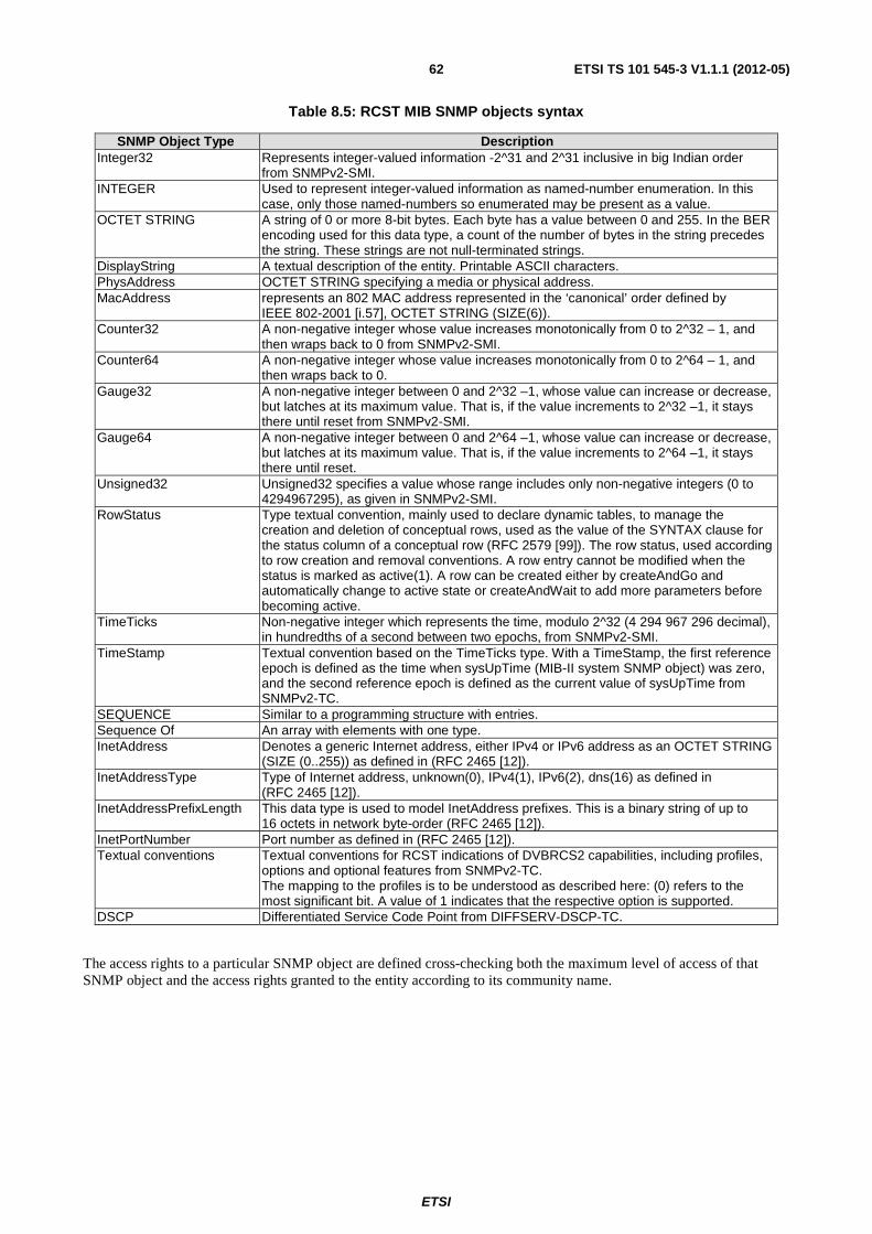
ETSI
ETSI TS 101 545-3 V1.1.1 (2012-05)62
Table 8.5: RCST MIB SNMP objects syntax
SNMP Object Type Description Integer32 Represents integer-valued information -2^31 and 2^31 inclusive in big Indian order
from SNMPv2-SMI. INTEGER Used to represent integer-valued information as named-number enumeration. In this
case, only those named-numbers so enumerated may be present as a value. OCTET STRING A string of 0 or more 8-bit bytes. Each byte has a value between 0 and 255. In the BER
encoding used for this data type, a count of the number of bytes in the string precedes the string. These strings are not null-terminated strings.
DisplayString A textual description of the entity. Printable ASCII characters. PhysAddress OCTET STRING specifying a media or physical address. MacAddress represents an 802 MAC address represented in the ‘canonical’ order defined by
IEEE 802-2001 [i.57], OCTET STRING (SIZE(6)). Counter32 A non-negative integer whose value increases monotonically from 0 to 2^32 – 1, and
then wraps back to 0 from SNMPv2-SMI. Counter64 A non-negative integer whose value increases monotonically from 0 to 2^64 – 1, and
then wraps back to 0. Gauge32 A non-negative integer between 0 and 2^32 –1, whose value can increase or decrease,
but latches at its maximum value. That is, if the value increments to 2^32 –1, it stays there until reset from SNMPv2-SMI.
Gauge64 A non-negative integer between 0 and 2^64 –1, whose value can increase or decrease, but latches at its maximum value. That is, if the value increments to 2^64 –1, it stays there until reset.
Unsigned32 Unsigned32 specifies a value whose range includes only non-negative integers (0 to 4294967295), as given in SNMPv2-SMI.
RowStatus Type textual convention, mainly used to declare dynamic tables, to manage the creation and deletion of conceptual rows, used as the value of the SYNTAX clause for the status column of a conceptual row (RFC 2579 [99]). The row status, used according to row creation and removal conventions. A row entry cannot be modified when the status is marked as active(1). A row can be created either by createAndGo and automatically change to active state or createAndWait to add more parameters before becoming active.
TimeTicks Non-negative integer which represents the time, modulo 2^32 (4 294 967 296 decimal), in hundredths of a second between two epochs, from SNMPv2-SMI.
TimeStamp Textual convention based on the TimeTicks type. With a TimeStamp, the first reference epoch is defined as the time when sysUpTime (MIB-II system SNMP object) was zero, and the second reference epoch is defined as the current value of sysUpTime from SNMPv2-TC.
SEQUENCE Similar to a programming structure with entries. Sequence Of An array with elements with one type. InetAddress Denotes a generic Internet address, either IPv4 or IPv6 address as an OCTET STRING
(SIZE (0..255)) as defined in (RFC 2465 [12]). InetAddressType Type of Internet address, unknown(0), IPv4(1), IPv6(2), dns(16) as defined in
(RFC 2465 [12]). InetAddressPrefixLength This data type is used to model InetAddress prefixes. This is a binary string of up to
16 octets in network byte-order (RFC 2465 [12]). InetPortNumber Port number as defined in (RFC 2465 [12]). Textual conventions Textual conventions for RCST indications of DVBRCS2 capabilities, including profiles,
options and optional features from SNMPv2-TC. The mapping to the profiles is to be understood as described here: (0) refers to the most significant bit. A value of 1 indicates that the respective option is supported.
DSCP Differentiated Service Code Point from DIFFSERV-DSCP-TC.
The access rights to a particular SNMP object are defined cross-checking both the maximum level of access of that SNMP object and the access rights granted to the entity according to its community name.
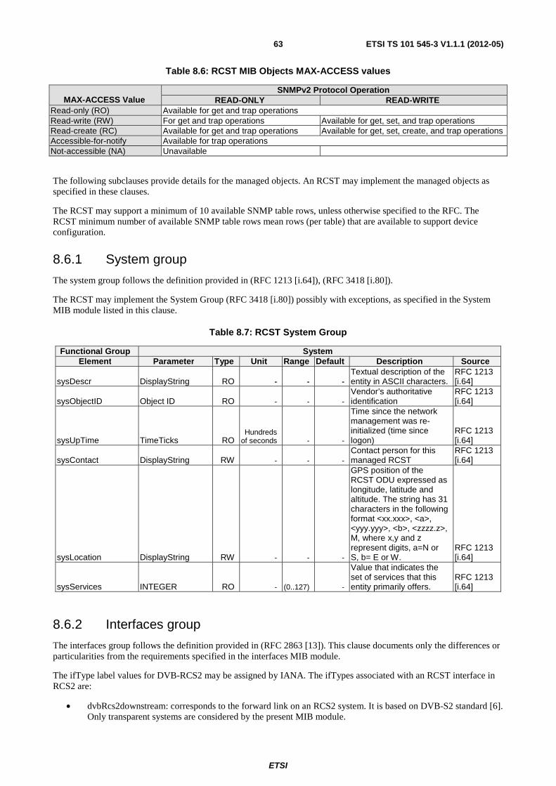
ETSI
ETSI TS 101 545-3 V1.1.1 (2012-05)63
Table 8.6: RCST MIB Objects MAX-ACCESS values
MAX-ACCESS Value
SNMPv2 Protocol Operation READ-ONLY READ-WRITE
Read-only (RO) Available for get and trap operations Read-write (RW) For get and trap operations Available for get, set, and trap operations Read-create (RC) Available for get and trap operations Available for get, set, create, and trap operations Accessible-for-notify Available for trap operations Not-accessible (NA) Unavailable
The following subclauses provide details for the managed objects. An RCST may implement the managed objects as specified in these clauses.
The RCST may support a minimum of 10 available SNMP table rows, unless otherwise specified to the RFC. The RCST minimum number of available SNMP table rows mean rows (per table) that are available to support device configuration.
8.6.1 System group
The system group follows the definition provided in (RFC 1213 [i.64]), (RFC 3418 [i.80]).
The RCST may implement the System Group (RFC 3418 [i.80]) possibly with exceptions, as specified in the System MIB module listed in this clause.
Table 8.7: RCST System Group
Functional Group System Element Parameter Type Unit Range Default Description Source
sysDescr DisplayString RO - - - Textual description of the entity in ASCII characters.
RFC 1213 [i.64]
sysObjectID Object ID RO - - - Vendor’s authoritative identification
RFC 1213 [i.64]
sysUpTime TimeTicks RO Hundreds
of seconds - -
Time since the network management was re-initialized (time since logon)
RFC 1213 [i.64]
sysContact DisplayString RW - - - Contact person for this managed RCST
RFC 1213 [i.64]
sysLocation DisplayString RW - - -
GPS position of the RCST ODU expressed as longitude, latitude and altitude. The string has 31 characters in the following format <xx.xxx>, <a>, <yyy.yyy>, <b>, <zzzz.z>, M, where x,y and z represent digits, a=N or S, b= E or W.
RFC 1213 [i.64]
sysServices INTEGER RO - (0..127) -
Value that indicates the set of services that this entity primarily offers.
RFC 1213 [i.64]
8.6.2 Interfaces group
The interfaces group follows the definition provided in (RFC 2863 [13]). This clause documents only the differences or particularities from the requirements specified in the interfaces MIB module.
The ifType label values for DVB-RCS2 may be assigned by IANA. The ifTypes associated with an RCST interface in RCS2 are:
• dvbRcs2downstream: corresponds to the forward link on an RCS2 system. It is based on DVB-S2 standard [6]. Only transparent systems are considered by the present MIB module.
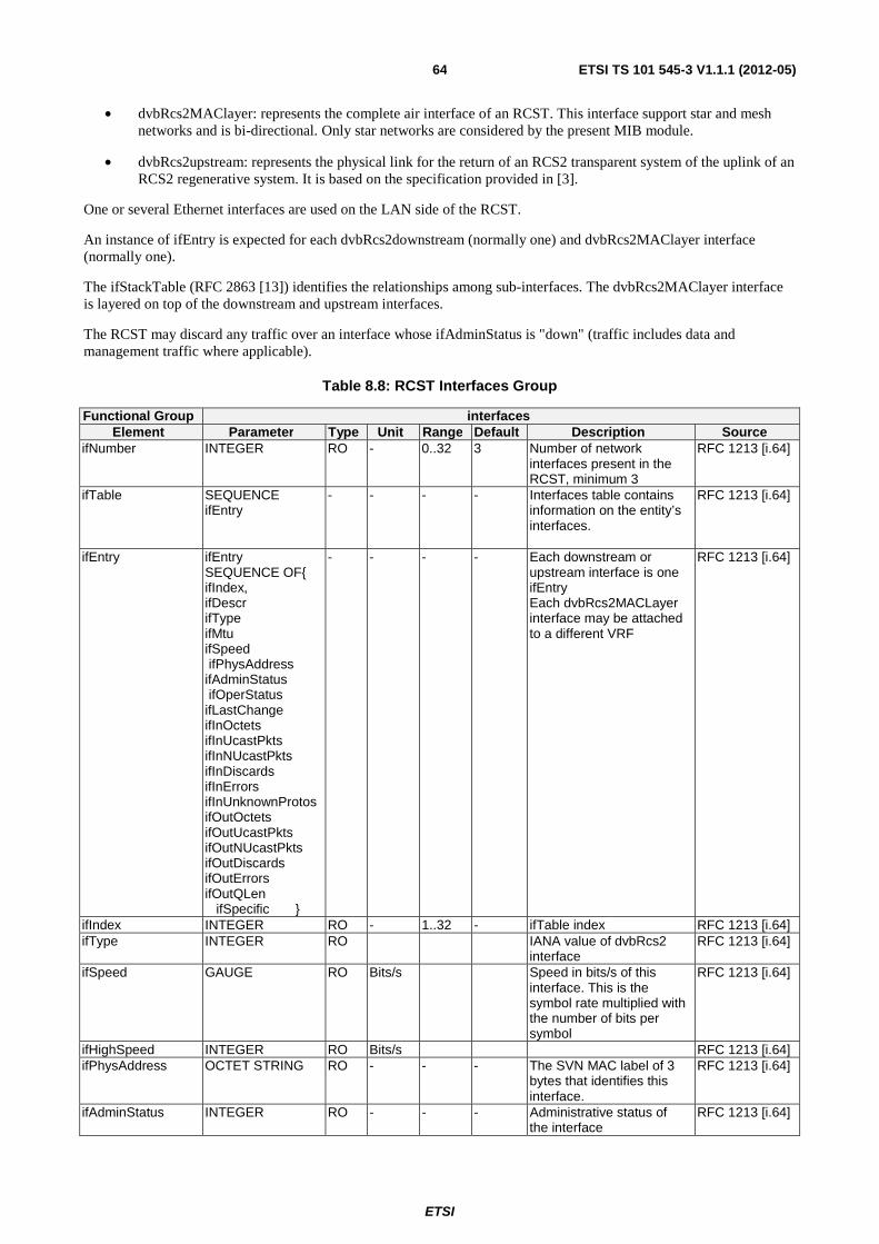
ETSI
ETSI TS 101 545-3 V1.1.1 (2012-05)64
• dvbRcs2MAClayer: represents the complete air interface of an RCST. This interface support star and mesh networks and is bi-directional. Only star networks are considered by the present MIB module.
• dvbRcs2upstream: represents the physical link for the return of an RCS2 transparent system of the uplink of an RCS2 regenerative system. It is based on the specification provided in [3].
One or several Ethernet interfaces are used on the LAN side of the RCST.
An instance of ifEntry is expected for each dvbRcs2downstream (normally one) and dvbRcs2MAClayer interface (normally one).
The ifStackTable (RFC 2863 [13]) identifies the relationships among sub-interfaces. The dvbRcs2MAClayer interface is layered on top of the downstream and upstream interfaces.
The RCST may discard any traffic over an interface whose ifAdminStatus is "down" (traffic includes data and management traffic where applicable).
Table 8.8: RCST Interfaces Group
Functional Group interfaces Element Parameter Type Unit Range Default Description Source
ifNumber INTEGER RO - 0..32 3 Number of network interfaces present in the RCST, minimum 3
RFC 1213 [i.64]
ifTable SEQUENCE ifEntry
- - - - Interfaces table contains information on the entity’s interfaces.
RFC 1213 [i.64]
ifEntry ifEntry SEQUENCE OF{ ifIndex, ifDescr ifType ifMtu ifSpeed ifPhysAddress ifAdminStatus ifOperStatus ifLastChange ifInOctets ifInUcastPkts ifInNUcastPkts ifInDiscards ifInErrors ifInUnknownProtos ifOutOctets ifOutUcastPkts ifOutNUcastPkts ifOutDiscards ifOutErrors ifOutQLen ifSpecific }
- - - - Each downstream or upstream interface is one ifEntry Each dvbRcs2MACLayer interface may be attached to a different VRF
RFC 1213 [i.64]
ifIndex INTEGER RO - 1..32 - ifTable index RFC 1213 [i.64] ifType INTEGER RO IANA value of dvbRcs2
interface RFC 1213 [i.64]
ifSpeed GAUGE RO Bits/s Speed in bits/s of this interface. This is the symbol rate multiplied with the number of bits per symbol
RFC 1213 [i.64]
ifHighSpeed INTEGER RO Bits/s RFC 1213 [i.64] ifPhysAddress OCTET STRING RO - - - The SVN MAC label of 3
bytes that identifies this interface.
RFC 1213 [i.64]
ifAdminStatus INTEGER RO - - - Administrative status of the interface
RFC 1213 [i.64]
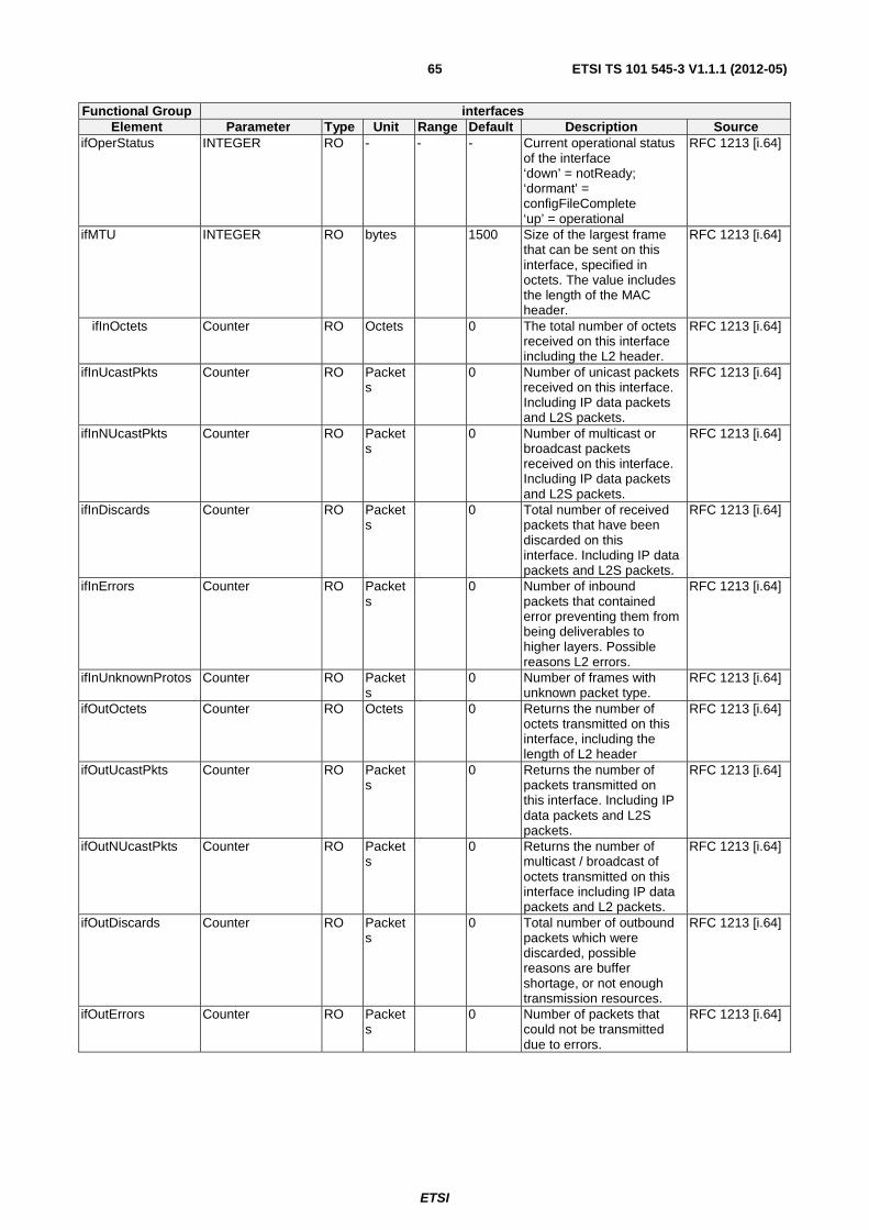
ETSI
ETSI TS 101 545-3 V1.1.1 (2012-05)65
Functional Group interfaces Element Parameter Type Unit Range Default Description Source
ifOperStatus INTEGER RO - - - Current operational status of the interface ‘down’ = notReady; ‘dormant’ = configFileComplete ‘up’ = operational
RFC 1213 [i.64]
ifMTU INTEGER RO bytes 1500 Size of the largest frame that can be sent on this interface, specified in octets. The value includes the length of the MAC header.
RFC 1213 [i.64]
ifInOctets Counter RO Octets 0 The total number of octets received on this interface including the L2 header.
RFC 1213 [i.64]
ifInUcastPkts Counter RO Packets
0 Number of unicast packets received on this interface. Including IP data packets and L2S packets.
RFC 1213 [i.64]
ifInNUcastPkts Counter RO Packets
0 Number of multicast or broadcast packets received on this interface. Including IP data packets and L2S packets.
RFC 1213 [i.64]
ifInDiscards Counter RO Packets
0 Total number of received packets that have been discarded on this interface. Including IP data packets and L2S packets.
RFC 1213 [i.64]
ifInErrors Counter RO Packets
0 Number of inbound packets that contained error preventing them from being deliverables to higher layers. Possible reasons L2 errors.
RFC 1213 [i.64]
ifInUnknownProtos Counter RO Packets
0 Number of frames with unknown packet type.
RFC 1213 [i.64]
ifOutOctets Counter RO Octets 0 Returns the number of octets transmitted on this interface, including the length of L2 header
RFC 1213 [i.64]
ifOutUcastPkts Counter RO Packets
0 Returns the number of packets transmitted on this interface. Including IP data packets and L2S packets.
RFC 1213 [i.64]
ifOutNUcastPkts Counter RO Packets
0 Returns the number of multicast / broadcast of octets transmitted on this interface including IP data packets and L2 packets.
RFC 1213 [i.64]
ifOutDiscards Counter RO Packets
0 Total number of outbound packets which were discarded, possible reasons are buffer shortage, or not enough transmission resources.
RFC 1213 [i.64]
ifOutErrors Counter RO Packets
0 Number of packets that could not be transmitted due to errors.
RFC 1213 [i.64]
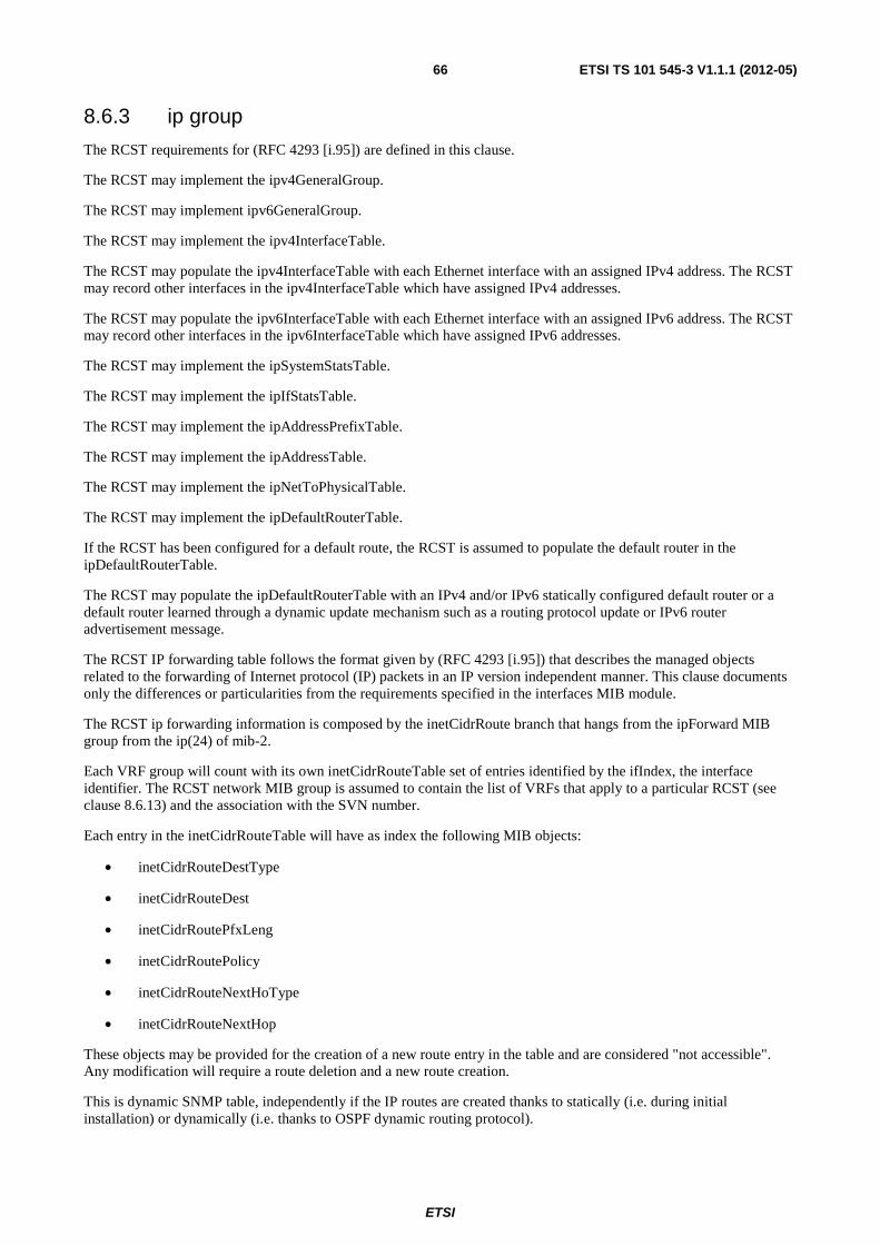
ETSI
ETSI TS 101 545-3 V1.1.1 (2012-05)66
8.6.3 ip group
The RCST requirements for (RFC 4293 [i.95]) are defined in this clause.
The RCST may implement the ipv4GeneralGroup.
The RCST may implement ipv6GeneralGroup.
The RCST may implement the ipv4InterfaceTable.
The RCST may populate the ipv4InterfaceTable with each Ethernet interface with an assigned IPv4 address. The RCST may record other interfaces in the ipv4InterfaceTable which have assigned IPv4 addresses.
The RCST may populate the ipv6InterfaceTable with each Ethernet interface with an assigned IPv6 address. The RCST may record other interfaces in the ipv6InterfaceTable which have assigned IPv6 addresses.
The RCST may implement the ipSystemStatsTable.
The RCST may implement the ipIfStatsTable.
The RCST may implement the ipAddressPrefixTable.
The RCST may implement the ipAddressTable.
The RCST may implement the ipNetToPhysicalTable.
The RCST may implement the ipDefaultRouterTable.
If the RCST has been configured for a default route, the RCST is assumed to populate the default router in the ipDefaultRouterTable.
The RCST may populate the ipDefaultRouterTable with an IPv4 and/or IPv6 statically configured default router or a default router learned through a dynamic update mechanism such as a routing protocol update or IPv6 router advertisement message.
The RCST IP forwarding table follows the format given by (RFC 4293 [i.95]) that describes the managed objects related to the forwarding of Internet protocol (IP) packets in an IP version independent manner. This clause documents only the differences or particularities from the requirements specified in the interfaces MIB module.
The RCST ip forwarding information is composed by the inetCidrRoute branch that hangs from the ipForward MIB group from the ip(24) of mib-2.
Each VRF group will count with its own inetCidrRouteTable set of entries identified by the ifIndex, the interface identifier. The RCST network MIB group is assumed to contain the list of VRFs that apply to a particular RCST (see clause 8.6.13) and the association with the SVN number.
Each entry in the inetCidrRouteTable will have as index the following MIB objects:
• inetCidrRouteDestType
• inetCidrRouteDest
• inetCidrRoutePfxLeng
• inetCidrRoutePolicy
• inetCidrRouteNextHoType
• inetCidrRouteNextHop
These objects may be provided for the creation of a new route entry in the table and are considered "not accessible". Any modification will require a route deletion and a new route creation.
This is dynamic SNMP table, independently if the IP routes are created thanks to statically (i.e. during initial installation) or dynamically (i.e. thanks to OSPF dynamic routing protocol).
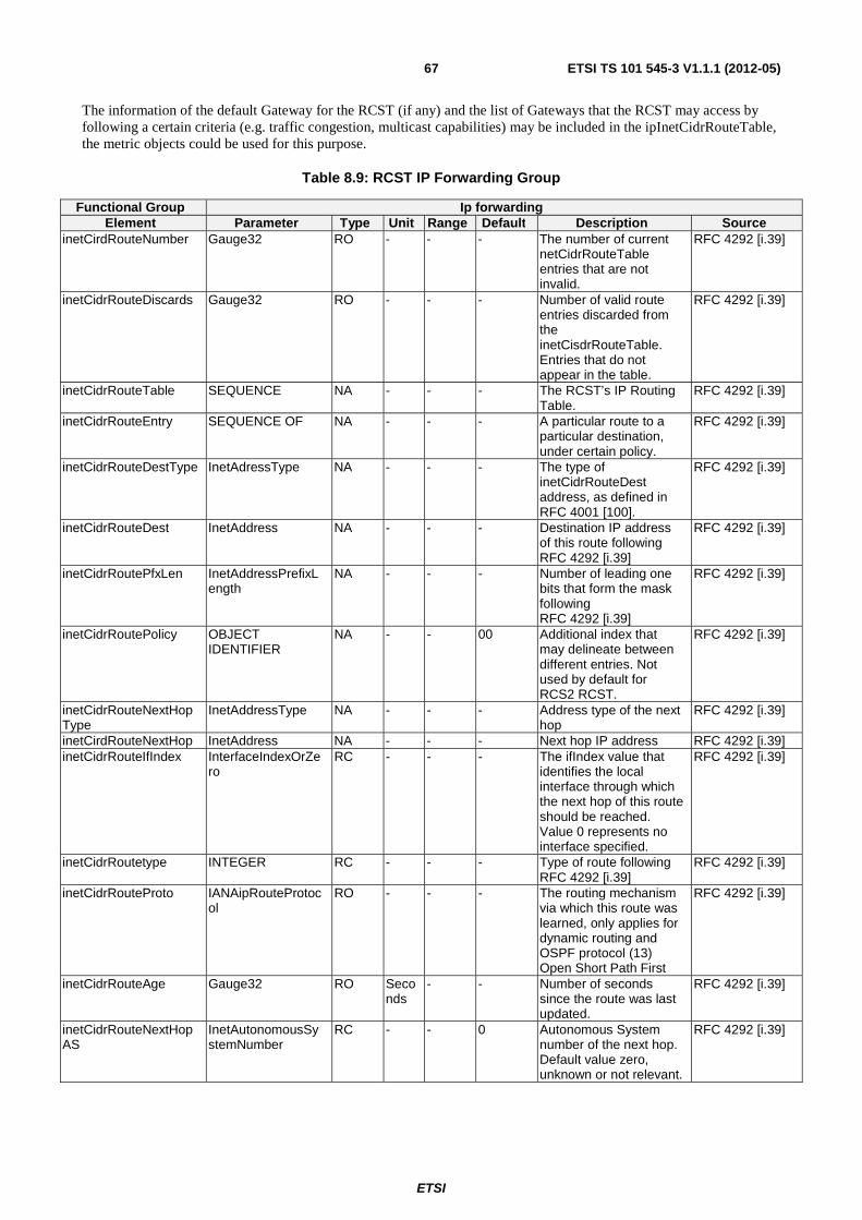
ETSI
ETSI TS 101 545-3 V1.1.1 (2012-05)67
The information of the default Gateway for the RCST (if any) and the list of Gateways that the RCST may access by following a certain criteria (e.g. traffic congestion, multicast capabilities) may be included in the ipInetCidrRouteTable, the metric objects could be used for this purpose.
Table 8.9: RCST IP Forwarding Group
Functional Group Ip forwarding Element Parameter Type Unit Range Default Description Source
inetCirdRouteNumber Gauge32 RO - - - The number of current netCidrRouteTable entries that are not invalid.
RFC 4292 [i.39]
inetCidrRouteDiscards Gauge32 RO - - - Number of valid route entries discarded from the inetCisdrRouteTable. Entries that do not appear in the table.
RFC 4292 [i.39]
inetCidrRouteTable SEQUENCE NA - - - The RCST’s IP Routing Table.
RFC 4292 [i.39]
inetCidrRouteEntry SEQUENCE OF NA - - - A particular route to a particular destination, under certain policy.
RFC 4292 [i.39]
inetCidrRouteDestType InetAdressType NA - - - The type of inetCidrRouteDest address, as defined in RFC 4001 [100].
RFC 4292 [i.39]
inetCidrRouteDest InetAddress NA - - - Destination IP address of this route following RFC 4292 [i.39]
RFC 4292 [i.39]
inetCidrRoutePfxLen InetAddressPrefixLength
NA - - - Number of leading one bits that form the mask following RFC 4292 [i.39]
RFC 4292 [i.39]
inetCidrRoutePolicy OBJECT IDENTIFIER
NA - - 00 Additional index that may delineate between different entries. Not used by default for RCS2 RCST.
RFC 4292 [i.39]
inetCidrRouteNextHopType
InetAddressType NA - - - Address type of the next hop
RFC 4292 [i.39]
inetCirdRouteNextHop InetAddress NA - - - Next hop IP address RFC 4292 [i.39] inetCidrRouteIfIndex InterfaceIndexOrZe
ro RC - - - The ifIndex value that
identifies the local interface through which the next hop of this route should be reached. Value 0 represents no interface specified.
RFC 4292 [i.39]
inetCidrRoutetype INTEGER RC - - - Type of route following RFC 4292 [i.39]
RFC 4292 [i.39]
inetCidrRouteProto IANAipRouteProtocol
RO - - - The routing mechanism via which this route was learned, only applies for dynamic routing and OSPF protocol (13) Open Short Path First
RFC 4292 [i.39]
inetCidrRouteAge Gauge32 RO Seconds
- - Number of seconds since the route was last updated.
RFC 4292 [i.39]
inetCidrRouteNextHopAS
InetAutonomousSystemNumber
RC - - 0 Autonomous System number of the next hop. Default value zero, unknown or not relevant.
RFC 4292 [i.39]
ETSI
ETSI TS 101 545-3 V1.1.1 (2012-05)68
Functional Group Ip forwarding Element Parameter Type Unit Range Default Description Source
inetCidrRouteMetric1 Integer32 RC - - -1 Primary metric for this route. The semantics of the metric are determined by OSPF. When not used, default value is -1
RFC 4292 [i.39]
inetCidrRouteMetric2 Integer32 RC - - -1 Alternative routing metric. Default not used, -1
RFC 4292 [i.39]
inetCidrRouteMetric3 Integer32 RC - - -1 Alternative routing metric. Default not used, -1
RFC 4292 [i.39]
inetCidrRouteMetric4 Integer32 RC - - -1 Alternative routing metric. Default not used, -1
RFC 4292 [i.39]
inetCidrRouteMetric5 Integer32 RC - - -1 Alternative routing metric. Default not used, -1
RFC 4292 [i.39]
inetCidrRouteStatus RowStatus RC - - - The row status, used according to row creation and removal conventions. A row entry cannot be modified when the status is marked as active(1)
RFC 4292 [i.39]
8.6.4 Ethernet Interface MIB group
The RCST may implement (RFC 3635 [i.87]) for each of its Ethernet interfaces.
8.6.5 icmp MIB group
The RCST may implement icmpStatsTable from (RFC 4293 [i.95]).
The RCST may implement icmpMsgStatsTable from (RFC 4293 [i.95]).
8.6.6 udp MIB group
The RCST may implement UDP-MIB (RFC 4113 [i.92]).
8.6.7 tcp MIB group
The RCST may implement TCP-MIB group (RFC 4022 [i.90]).
8.6.8 snmp MIB group
The RCST may implement the SNMP group from (RFC 3418 [i.80]). This group provides SNMP protocol statistics and protocol error counters.
The snmpCommunityTable is defined in the "SNMP Community MIB Module" section of (RFC 3584 [i.84]).
The snmpTargetAddrTable is defined in the "Definitions" section of (RFC 3413 [i.75]).
The RCST may create one row in snmpTargetAddrTable for each SNMPv2c Transport Address Access.
SNMP access is controlled and specified by the MIB objects in (RFC 3315 [i.35]) through (RFC 3415 [i.77]), and (RFC 3584 [i.84]). The RCST may have several interfaces. If SNMP access filters are applied to RCST IfIndex 1, the RCST may apply the same filters to the "Additional LAN interfaces".
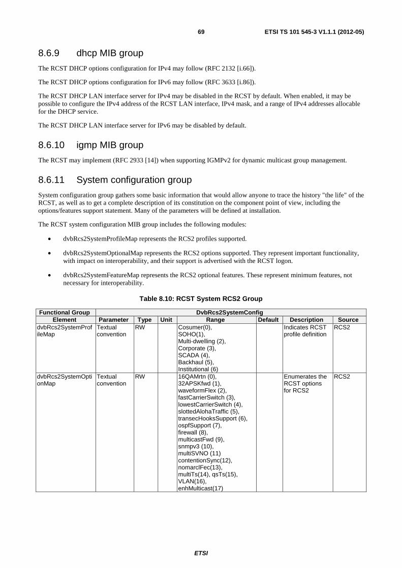
ETSI
ETSI TS 101 545-3 V1.1.1 (2012-05)69
8.6.9 dhcp MIB group
The RCST DHCP options configuration for IPv4 may follow (RFC 2132 [i.66]).
The RCST DHCP options configuration for IPv6 may follow (RFC 3633 [i.86]).
The RCST DHCP LAN interface server for IPv4 may be disabled in the RCST by default. When enabled, it may be possible to configure the IPv4 address of the RCST LAN interface, IPv4 mask, and a range of IPv4 addresses allocable for the DHCP service.
The RCST DHCP LAN interface server for IPv6 may be disabled by default.
8.6.10 igmp MIB group
The RCST may implement (RFC 2933 [14]) when supporting IGMPv2 for dynamic multicast group management.
8.6.11 System configuration group
System configuration group gathers some basic information that would allow anyone to trace the history "the life" of the RCST, as well as to get a complete description of its constitution on the component point of view, including the options/features support statement. Many of the parameters will be defined at installation.
The RCST system configuration MIB group includes the following modules:
• dvbRcs2SystemProfileMap represents the RCS2 profiles supported.
• dvbRcs2SystemOptionalMap represents the RCS2 options supported. They represent important functionality, with impact on interoperability, and their support is advertised with the RCST logon.
• dvbRcs2SystemFeatureMap represents the RCS2 optional features. These represent minimum features, not necessary for interoperability.
Table 8.10: RCST System RCS2 Group
Functional Group DvbRcs2SystemConfig Element Parameter Type Unit Range Default Description Source
dvbRcs2SystemProfileMap
Textual convention
RW Cosumer(0), SOHO(1), Multi-dwelling (2), Corporate (3), SCADA (4), Backhaul (5), Institutional (6)
Indicates RCST profile definition
RCS2
dvbRcs2SystemOptionMap
Textual convention
RW 16QAMrtn (0), 32APSKfwd (1), waveformFlex (2), fastCarrierSwitch (3), lowestCarrierSwitch (4), slottedAlohaTraffic (5), transecHooksSupport (6), ospfSupport (7), firewall (8), multicastFwd (9), snmpv3 (10), multiSVNO (11) contentionSync(12), nomarclFec(13), multiTs(14), qsTs(15), VLAN(16), enhMulticast(17)
Enumerates the RCST options for RCS2
RCS2
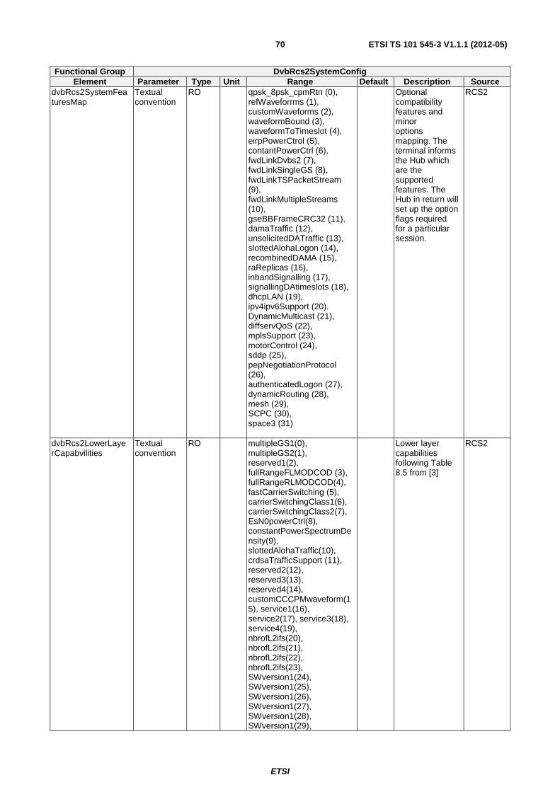
ETSI
ETSI TS 101 545-3 V1.1.1 (2012-05)70
Functional Group DvbRcs2SystemConfig Element Parameter Type Unit Range Default Description Source
dvbRcs2SystemFeaturesMap
Textual convention
RO qpsk_8psk_cpmRtn (0), refWaveforrms (1), customWaveforms (2), waveformBound (3), waveformToTimeslot (4), eirpPowerCtrol (5), contantPowerCtrl (6), fwdLinkDvbs2 (7), fwdLinkSingleGS (8), fwdLinkTSPacketStream (9), fwdLinkMultipleStreams (10), gseBBFrameCRC32 (11), damaTraffic (12), unsolicitedDATraffic (13), slottedAlohaLogon (14), recombinedDAMA (15), raReplicas (16), inbandSignalling (17), signallingDAtimeslots (18), dhcpLAN (19), ipv4ipv6Support (20). DynamicMulticast (21), diffservQoS (22), mplsSupport (23), motorControl (24), sddp (25), pepNegotiationProtocol (26), authenticatedLogon (27), dynamicRouting (28), mesh (29), SCPC (30), space3 (31)
Optional compatibility features and minor options mapping. The terminal informs the Hub which are the supported features. The Hub in return will set up the option flags required for a particular session.
RCS2
dvbRcs2LowerLayerCapabvilities
Textual convention
RO multipleGS1(0), multipleGS2(1), reserved1(2), fullRangeFLMODCOD (3), fullRangeRLMODCOD(4), fastCarrierSwitching (5), carrierSwitchingClass1(6), carrierSwitchingClass2(7), EsN0powerCtrl(8), constantPowerSpectrumDensity(9), slottedAlohaTraffic(10), crdsaTrafficSupport (11), reserved2(12), reserved3(13), reserved4(14), customCCCPMwaveform(15), service1(16), service2(17), service3(18), service4(19), nbrofL2ifs(20), nbrofL2ifs(21), nbrofL2ifs(22), nbrofL2ifs(23), SWversion1(24), SWversion1(25), SWversion1(26), SWversion1(27), SWversion1(28), SWversion1(29),
Lower layer capabilities following Table 8.5 from [3]
RCS2
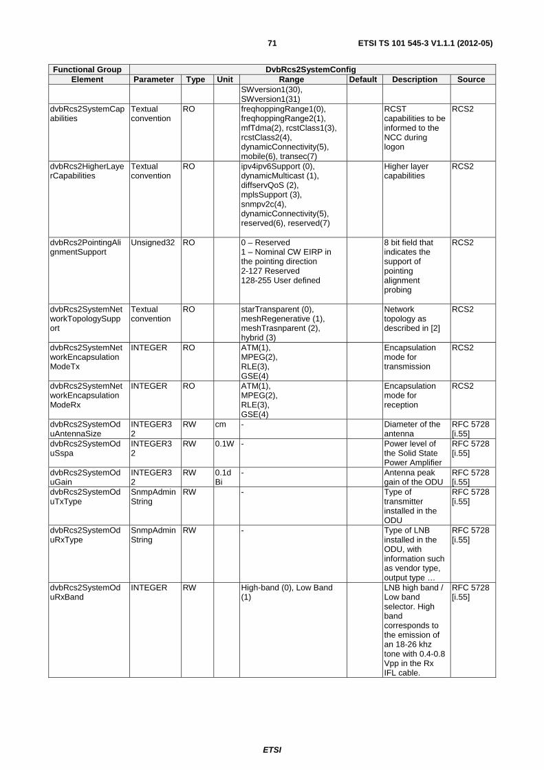
ETSI
ETSI TS 101 545-3 V1.1.1 (2012-05)71
Functional Group DvbRcs2SystemConfig Element Parameter Type Unit Range Default Description Source
SWversion1(30), SWversion1(31)
dvbRcs2SystemCapabilities
Textual convention
RO freqhoppingRange1(0), freqhoppingRange2(1), mfTdma(2), rcstClass1(3), rcstClass2(4), dynamicConnectivity(5), mobile(6), transec(7)
RCST capabilities to be informed to the NCC during logon
RCS2
dvbRcs2HigherLayerCapabilities
Textual convention
RO ipv4ipv6Support (0), dynamicMulticast (1), diffservQoS (2), mplsSupport (3), snmpv2c(4), dynamicConnectivity(5), reserved(6), reserved(7)
Higher layer capabilities
RCS2
dvbRcs2PointingAlignmentSupport
Unsigned32 RO 0 – Reserved 1 – Nominal CW EIRP in the pointing direction 2-127 Reserved 128-255 User defined
8 bit field that indicates the support of pointing alignment probing
RCS2
dvbRcs2SystemNetworkTopologySupport
Textual convention
RO starTransparent (0), meshRegenerative (1), meshTrasnparent (2), hybrid (3)
Network topology as described in [2]
RCS2
dvbRcs2SystemNetworkEncapsulationModeTx
INTEGER RO ATM(1), MPEG(2), RLE(3), GSE(4)
Encapsulation mode for transmission
RCS2
dvbRcs2SystemNetworkEncapsulationModeRx
INTEGER RO ATM(1), MPEG(2), RLE(3), GSE(4)
Encapsulation mode for reception
RCS2
dvbRcs2SystemOduAntennaSize
INTEGER32
RW cm - Diameter of the antenna
RFC 5728 [i.55]
dvbRcs2SystemOduSspa
INTEGER32
RW 0.1W - Power level of the Solid State Power Amplifier
RFC 5728 [i.55]
dvbRcs2SystemOduGain
INTEGER32
RW 0.1dBi
- Antenna peak gain of the ODU
RFC 5728 [i.55]
dvbRcs2SystemOduTxType
SnmpAdminString
RW - Type of transmitter installed in the ODU
RFC 5728 [i.55]
dvbRcs2SystemOduRxType
SnmpAdminString
RW - Type of LNB installed in the ODU, with information such as vendor type, output type …
RFC 5728 [i.55]
dvbRcs2SystemOduRxBand
INTEGER RW High-band (0), Low Band (1)
LNB high band / Low band selector. High band corresponds to the emission of an 18-26 khz tone with 0.4-0.8 Vpp in the Rx IFL cable.
RFC 5728 [i.55]
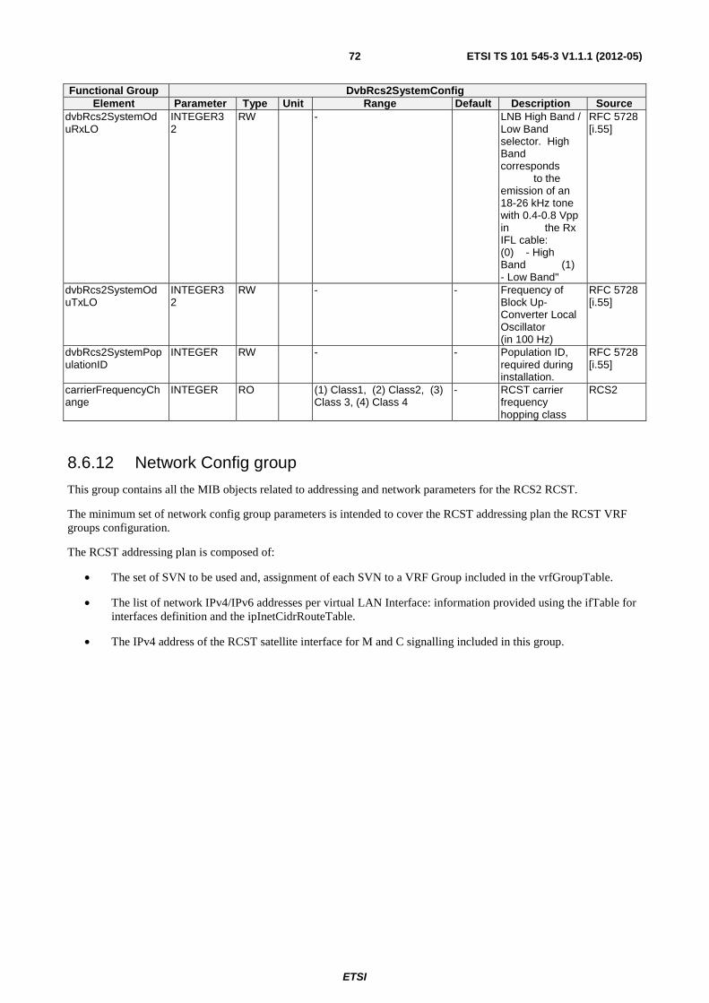
ETSI
ETSI TS 101 545-3 V1.1.1 (2012-05)72
Functional Group DvbRcs2SystemConfig Element Parameter Type Unit Range Default Description Source
dvbRcs2SystemOduRxLO
INTEGER32
RW - LNB High Band / Low Band selector. High Band corresponds to the emission of an 18-26 kHz tone with 0.4-0.8 Vpp in the Rx IFL cable: (0) - High Band (1) - Low Band"
RFC 5728 [i.55]
dvbRcs2SystemOduTxLO
INTEGER32
RW - - Frequency of Block Up-Converter Local Oscillator (in 100 Hz)
RFC 5728 [i.55]
dvbRcs2SystemPopulationID
INTEGER RW - - Population ID, required during installation.
RFC 5728 [i.55]
carrierFrequencyChange
INTEGER RO (1) Class1, (2) Class2, (3) Class 3, (4) Class 4
- RCST carrier frequency hopping class
RCS2
8.6.12 Network Config group
This group contains all the MIB objects related to addressing and network parameters for the RCS2 RCST.
The minimum set of network config group parameters is intended to cover the RCST addressing plan the RCST VRF groups configuration.
The RCST addressing plan is composed of:
• The set of SVN to be used and, assignment of each SVN to a VRF Group included in the vrfGroupTable.
• The list of network IPv4/IPv6 addresses per virtual LAN Interface: information provided using the ifTable for interfaces definition and the ipInetCidrRouteTable.
• The IPv4 address of the RCST satellite interface for M and C signalling included in this group.
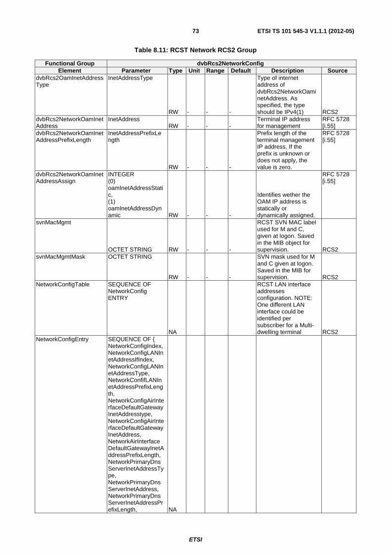
ETSI
ETSI TS 101 545-3 V1.1.1 (2012-05)73
Table 8.11: RCST Network RCS2 Group
Functional Group dvbRcs2NetworkConfig Element Parameter Type Unit Range Default Description Source
dvbRcs2OamInetAddressType
InetAddressType
RW - - -
Type of internet address of dvbRcs2NetworkOaminetAddress. As specified, the type should be IPv4(1) RCS2
dvbRcs2NetworkOamInetAddress
InetAddress RW - - -
Terminal IP address for management
RFC 5728 [i.55]
dvbRcs2NetworkOamInetAddressPrefixLength
InetAddressPrefixLength
RW - - -
Prefix length of the terminal management IP address. If the prefix is unknown or does not apply, the value is zero.
RFC 5728 [i.55]
dvbRcs2NetworkOamInetAddressAssign
INTEGER (0) oamInetAddressStatic, (1) oamInetAddressDynamic RW - - -
Identifies wether the OAM IP address is statically or dynamically assigned.
RFC 5728 [i.55]
svnMacMgmt
OCTET STRING RW - - -
RCST SVN MAC label used for M and C, given at logon. Saved in the MIB object for supervision. RCS2
svnMacMgmtMask OCTET STRING
RW - - -
SVN mask used for M and C given at logon. Saved in the MIB for supervision. RCS2
NetworkConfigTable SEQUENCE OF NetworkConfig ENTRY
NA
RCST LAN interface addresses configuration. NOTE: One different LAN interface could be identified per subscriber for a Multi-dwelling terminal RCS2
NetworkConfigEntry SEQUENCE OF { NetworkConfigIndex, NetworkConfigLANInetAddressIfIndex, NetworkConfigLANInetAddressType, NetworkConfifLANInetAddressPrefixLength, NetworkConfigAirInterfaceDefaultGatewayInetAddresstype, NetworkConfigAirInterfaceDefaultGatewayInetAddress, NetworkAirInterfaceDefaultGatewayInetAddressPrefixLength, NetworkPrimaryDnsServerInetAddressType, NetworkPrimaryDnsServerInetAddress, NetworkPrimaryDnsServerInetAddressPrefixLength, NA
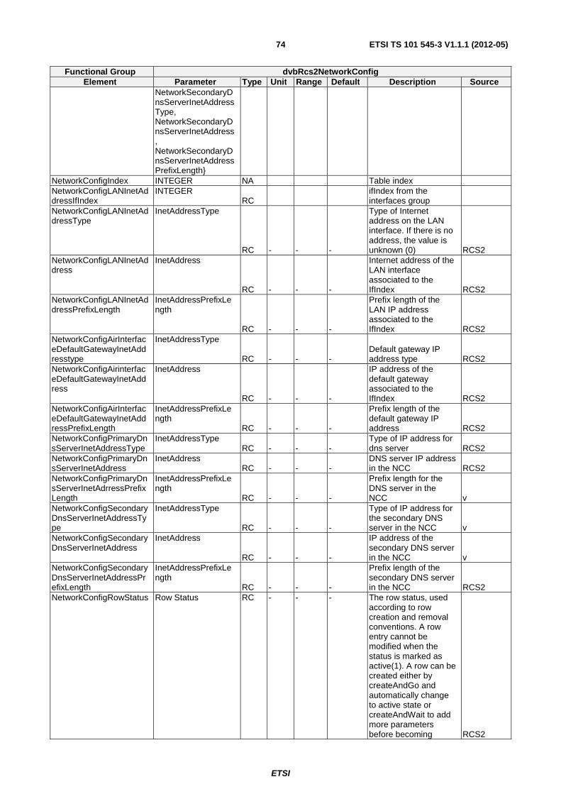
ETSI
ETSI TS 101 545-3 V1.1.1 (2012-05)74
Functional Group dvbRcs2NetworkConfig Element Parameter Type Unit Range Default Description Source
NetworkSecondaryDnsServerInetAddressType, NetworkSecondaryDnsServerInetAddress, NetworkSecondaryDnsServerInetAddressPrefixLength}
NetworkConfigIndex INTEGER NA Table index NetworkConfigLANInetAddressIfIndex
INTEGER RC
ifIndex from the interfaces group
NetworkConfigLANInetAddressType
InetAddressType
RC - - -
Type of Internet address on the LAN interface. If there is no address, the value is unknown (0) RCS2
NetworkConfigLANInetAddress
InetAddress
RC - - -
Internet address of the LAN interface associated to the IfIndex RCS2
NetworkConfigLANInetAddressPrefixLength
InetAddressPrefixLength
RC - - -
Prefix length of the LAN IP address associated to the IfIndex RCS2
NetworkConfigAirInterfaceDefaultGatewayInetAddresstype
InetAddressType
RC - - - Default gateway IP address type RCS2
NetworkConfigAirinterfaceDefaultGatewayInetAddress
InetAddress
RC - - -
IP address of the default gateway associated to the IfIndex RCS2
NetworkConfigAirInterfaceDefaultGatewayInetAddressPrefixLength
InetAddressPrefixLength
RC - - -
Prefix length of the default gateway IP address RCS2
NetworkConfigPrimaryDnsServerInetAddressType
InetAddressType RC - - -
Type of IP address for dns server RCS2
NetworkConfigPrimaryDnsServerInetAddress
InetAddress RC - - -
DNS server IP address in the NCC RCS2
NetworkConfigPrimaryDnsServerInetAdrressPrefixLength
InetAddressPrefixLength
RC - - -
Prefix length for the DNS server in the NCC v
NetworkConfigSecondaryDnsServerInetAddressType
InetAddressType
RC - - -
Type of IP address for the secondary DNS server in the NCC v
NetworkConfigSecondaryDnsServerInetAddress
InetAddress
RC - - -
IP address of the secondary DNS server in the NCC v
NetworkConfigSecondaryDnsServerInetAddressPrefixLength
InetAddressPrefixLength
RC - - -
Prefix length of the secondary DNS server in the NCC RCS2
NetworkConfigRowStatus Row Status RC - - - The row status, used according to row creation and removal conventions. A row entry cannot be modified when the status is marked as active(1). A row can be created either by createAndGo and automatically change to active state or createAndWait to add more parameters before becoming RCS2

ETSI
ETSI TS 101 545-3 V1.1.1 (2012-05)75
Functional Group dvbRcs2NetworkConfig Element Parameter Type Unit Range Default Description Source
active. dvbRcs2NetworkNmcMgtInetAddress
InetAddressType
RW - - -
Type of address of the management server in the NMC
RFC 5728 [i.55]
dvbRcs2NetworkNmcMgtInetAddress
InetAddress RW - - - NMC IP address
RFC 5728 [i.55]
dvbRcs2NetworkNmcMgtinetAddressPrefixLength
InetAddressPrefixLength RW - - -
NMC IP address prefix length
RFC 5728 [i.55]
dvbRcs2NetworkConfigFileDownloadUrl
Uri (SIZE(0..65535))
RW - - -
Fullpath name for the configuration file download.
RFC 5728 [i.55]
dvbRcs2NetworkInstallLogFileDownlaodUrl
Uri (SIZE(0..65535))
RW - - -
Full path name of the installation log file to download
RFC 5728 [i.55]
dvbRcs2NetworkConfigFileUploadUrl
Uri (SIZE(0..65535))
RW - - -
Fullpath name for the configuration file upload.
RFC 5728 [i.55]
dvbRcs2NetworklogFileUploadUrl
Uri (SIZE(0..65535)) RW - - -
Full path name for the event log file
RFC 5728 [i.55]
dvbRcs2NetworkInstallLogFileUploadUrl
Uri (SIZE(0..65535)) RW - - -
Full path name for the installation log file
RFC 5728 [i.55]
8.6.13 L3VirtualRoutingForwardingConfig group
These set of parameters determine L3 virtual routing forwarding configuration of the RCST.
Table 8.12: RCST VRF RCS2 Group
Functional Group dvbRcs2 L3VirtualRoutingForwardingConfig Element Parameter Type Unit Range Default Description Source
vrfGroupTable SEQUENCE OF vrfGroupEntry
NA - - VRF group table that contains the IP routing forwarding information of the RCST per interface
RCS2
vrfGroupEntry SEQUENCE { vrfGroupIndex, vrfGroupSVNnumber, vrfSVNMAClabel, vrfGroupIfInterface, vrfGroupSVNMask, vrfSVNmtu, vrfGroupIfInterface, vrfOSPFrouting, vrfMulticastMappingMethod vrfMulticastFwd vrfMulticastRtn vrfIgmpVersion vrfIgmpQuerierLAN vrfIgmpProxy vrfIgmpQuerierSAT vrfIgmpForward vrfPimSM vrfMldQuerierLAN vrfMldProxy vrfMldQuerierSAT vrfMldForward vrfGroupStatusRow}
NA - - VRF group table entry, each entry will identify a particular SVN association to one VRF group, and the corresponding interface ifIndex.
RCS2
vrfGroupIndex INTEGER NA - - VRF group table index or VRF group identified
RCS2
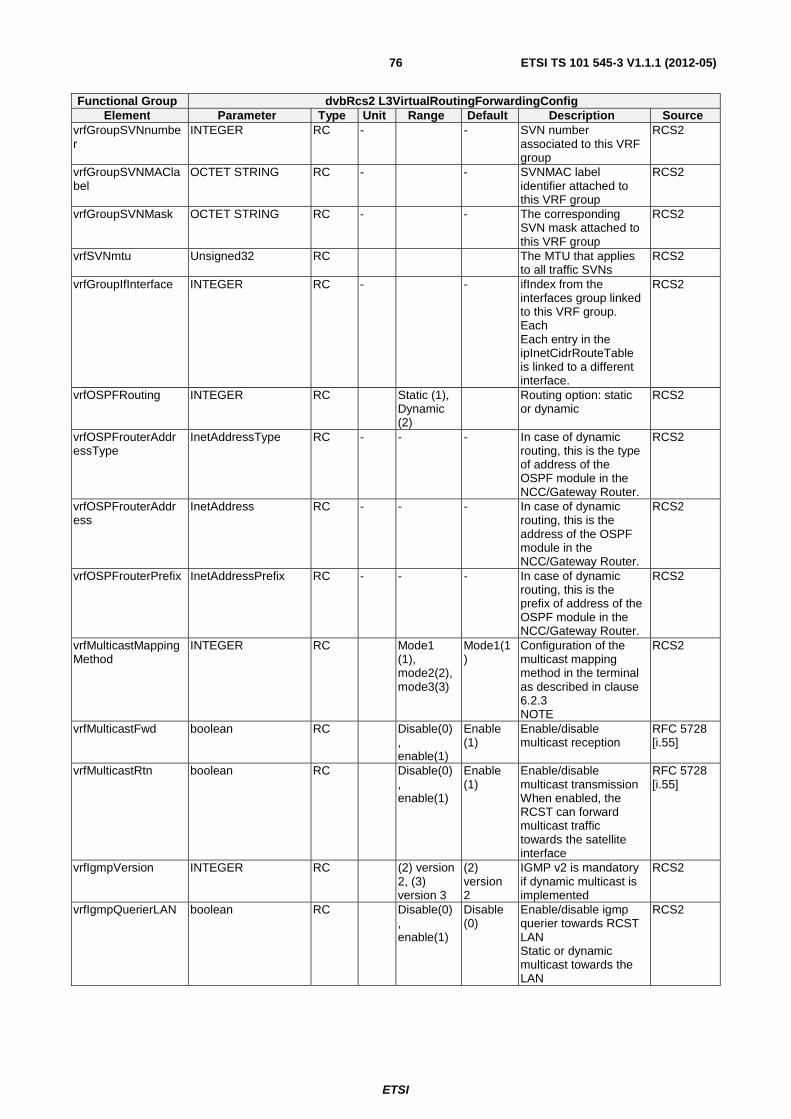
ETSI
ETSI TS 101 545-3 V1.1.1 (2012-05)76
Functional Group dvbRcs2 L3VirtualRoutingForwardingConfig Element Parameter Type Unit Range Default Description Source
vrfGroupSVNnumber
INTEGER RC - - SVN number associated to this VRF group
RCS2
vrfGroupSVNMAClabel
OCTET STRING RC - - SVNMAC label identifier attached to this VRF group
RCS2
vrfGroupSVNMask OCTET STRING RC - - The corresponding SVN mask attached to this VRF group
RCS2
vrfSVNmtu Unsigned32 RC The MTU that applies to all traffic SVNs
RCS2
vrfGroupIfInterface INTEGER RC - - ifIndex from the interfaces group linked to this VRF group. Each Each entry in the ipInetCidrRouteTable is linked to a different interface.
RCS2
vrfOSPFRouting INTEGER RC Static (1), Dynamic (2)
Routing option: static or dynamic
RCS2
vrfOSPFrouterAddressType
InetAddressType RC - - - In case of dynamic routing, this is the type of address of the OSPF module in the NCC/Gateway Router.
RCS2
vrfOSPFrouterAddress
InetAddress RC - - - In case of dynamic routing, this is the address of the OSPF module in the NCC/Gateway Router.
RCS2
vrfOSPFrouterPrefix InetAddressPrefix RC - - - In case of dynamic routing, this is the prefix of address of the OSPF module in the NCC/Gateway Router.
RCS2
vrfMulticastMappingMethod
INTEGER RC Mode1 (1), mode2(2), mode3(3)
Mode1(1)
Configuration of the multicast mapping method in the terminal as described in clause 6.2.3 NOTE
RCS2
vrfMulticastFwd boolean RC Disable(0), enable(1)
Enable (1)
Enable/disable multicast reception
RFC 5728 [i.55]
vrfMulticastRtn boolean RC Disable(0), enable(1)
Enable (1)
Enable/disable multicast transmission When enabled, the RCST can forward multicast traffic towards the satellite interface
RFC 5728 [i.55]
vrfIgmpVersion INTEGER RC (2) version 2, (3) version 3
(2) version 2
IGMP v2 is mandatory if dynamic multicast is implemented
RCS2
vrfIgmpQuerierLAN boolean RC Disable(0), enable(1)
Disable (0)
Enable/disable igmp querier towards RCST LAN Static or dynamic multicast towards the LAN
RCS2
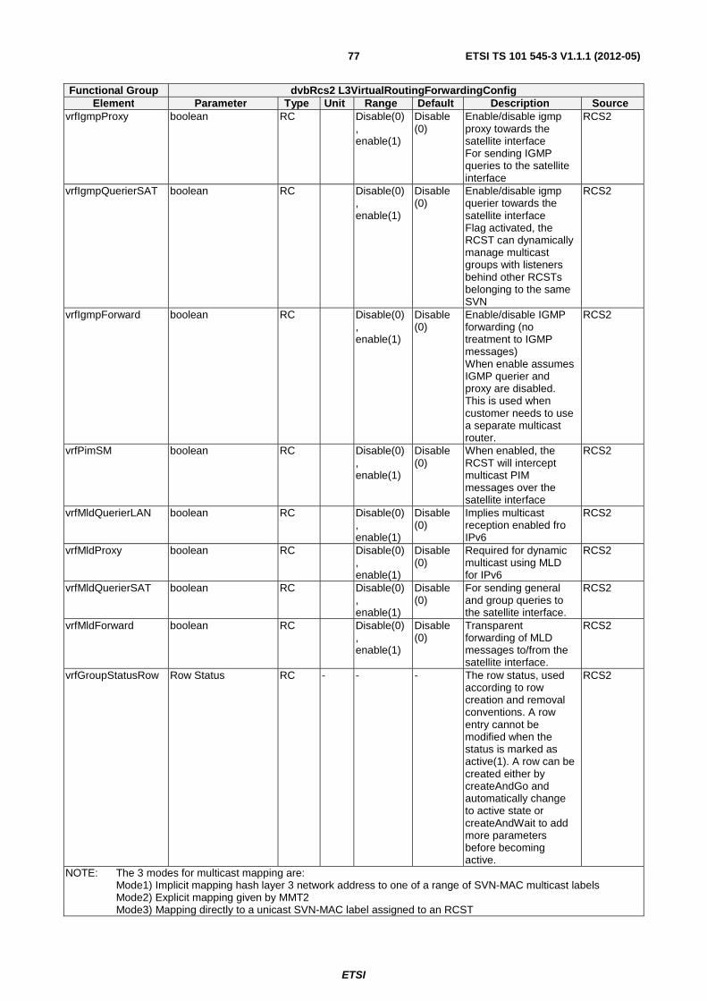
ETSI
ETSI TS 101 545-3 V1.1.1 (2012-05)77
Functional Group dvbRcs2 L3VirtualRoutingForwardingConfig Element Parameter Type Unit Range Default Description Source
vrfIgmpProxy boolean RC Disable(0), enable(1)
Disable (0)
Enable/disable igmp proxy towards the satellite interface For sending IGMP queries to the satellite interface
RCS2
vrfIgmpQuerierSAT boolean RC Disable(0), enable(1)
Disable (0)
Enable/disable igmp querier towards the satellite interface Flag activated, the RCST can dynamically manage multicast groups with listeners behind other RCSTs belonging to the same SVN
RCS2
vrfIgmpForward boolean RC Disable(0), enable(1)
Disable (0)
Enable/disable IGMP forwarding (no treatment to IGMP messages) When enable assumes IGMP querier and proxy are disabled. This is used when customer needs to use a separate multicast router.
RCS2
vrfPimSM boolean RC Disable(0), enable(1)
Disable (0)
When enabled, the RCST will intercept multicast PIM messages over the satellite interface
RCS2
vrfMldQuerierLAN boolean RC Disable(0), enable(1)
Disable (0)
Implies multicast reception enabled fro IPv6
RCS2
vrfMldProxy boolean RC Disable(0), enable(1)
Disable (0)
Required for dynamic multicast using MLD for IPv6
RCS2
vrfMldQuerierSAT boolean RC Disable(0), enable(1)
Disable (0)
For sending general and group queries to the satellite interface.
RCS2
vrfMldForward boolean RC Disable(0), enable(1)
Disable (0)
Transparent forwarding of MLD messages to/from the satellite interface.
RCS2
vrfGroupStatusRow Row Status RC - - - The row status, used according to row creation and removal conventions. A row entry cannot be modified when the status is marked as active(1). A row can be created either by createAndGo and automatically change to active state or createAndWait to add more parameters before becoming active.
RCS2
NOTE: The 3 modes for multicast mapping are: Mode1) Implicit mapping hash layer 3 network address to one of a range of SVN-MAC multicast labels Mode2) Explicit mapping given by MMT2 Mode3) Mapping directly to a unicast SVN-MAC label assigned to an RCST
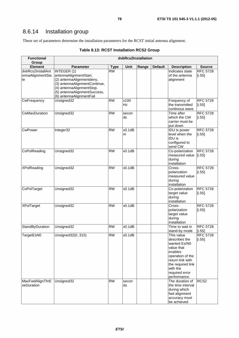
ETSI
ETSI TS 101 545-3 V1.1.1 (2012-05)78
8.6.14 Installation group
These set of parameters determine the installation parameters for the RCST initial antenna alignment.
Table 8.13: RCST Installation RCS2 Group
Functional Group
dvbRcs2Installation
Element Parameter Type Unit Range Default Description Source dvbRcs2InstallAntennaAlignmentState
INTEGER (1) antennaAlignmentStart, (2) antennaAlignmentdeny, (3) antennaAlignmentContinue, (4) antennaAlignmentStop, (5) antennaAlignmentSuccess, (6) antennaAlignmentFail
RW Indicates state of the antenna alignment
RFC 5728 [i.55]
CwFrequency Unsigned32 RW x100 Hz
Frequency of the transmitted continous wave
RFC 5728 [i.55]
CwMaxDuration Unsigned32 RW seconds
Time after which the CW carrier must be put down
RFC 5728 [i.55]
CwPower Integer32 RW x0.1dBm
IDU tx power level when the IDU is configured to send CW.
RFC 5728 [i.55]
CoPolReading Unsigned32 RW x0.1dB Co-polarization measured value during installation
RFC 5728 [i.55]
XPolReading Unsigned32 RW x0.1dB Cross-polarization measured value during installation
RFC 5728 [i.55]
CoPolTarget Unsigned32 RW x0.1dB Co-polarization target value during installation
RFC 5728 [i.55]
XPolTarget Unsigned32 RW x0.1dB Cross-polarization target value during installation
RFC 5728 [i.55]
StandByDuration Unsigned32 RW x0.1dB Time to wait in stand-by mode
RFC 5728 [i.55]
TargetEsN0 Unsigned32(0..315) RW x0.1dB This value describes the wanted Es/N0 value that enables operation of the return link with the required link with the required error performance.
RFC 5728 [i.55]
MaxFwdAlignThrExeDuration
Unsigned32 RW seconds
The duration of the time interval during which fwd alignment accuracy must be achieved
RCS2
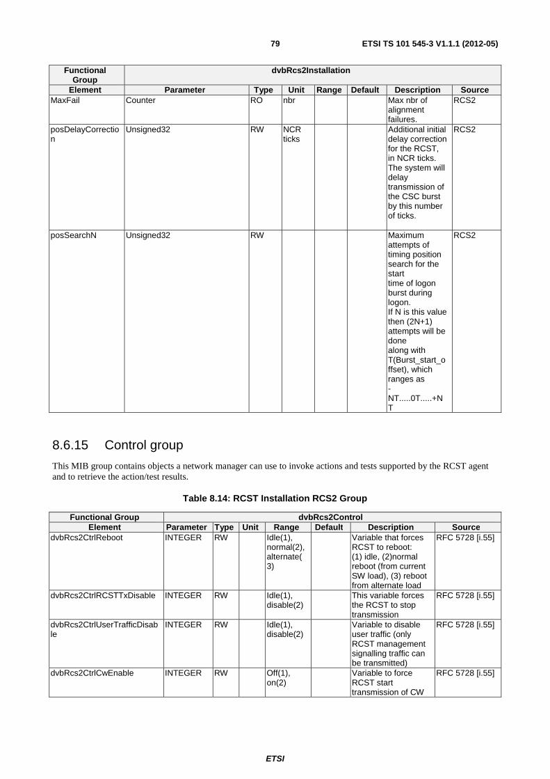
ETSI
ETSI TS 101 545-3 V1.1.1 (2012-05)79
Functional Group
dvbRcs2Installation
Element Parameter Type Unit Range Default Description Source MaxFail Counter RO nbr Max nbr of
alignment failures.
RCS2
posDelayCorrection
Unsigned32 RW NCR ticks
Additional initial delay correction for the RCST, in NCR ticks. The system will delay transmission of the CSC burst by this number of ticks.
RCS2
posSearchN Unsigned32 RW Maximum attempts of timing position search for the start time of logon burst during logon. If N is this value then (2N+1) attempts will be done along with T(Burst_start_offset), which ranges as -NT.....0T.....+NT
RCS2
8.6.15 Control group
This MIB group contains objects a network manager can use to invoke actions and tests supported by the RCST agent and to retrieve the action/test results.
Table 8.14: RCST Installation RCS2 Group
Functional Group dvbRcs2Control Element Parameter Type Unit Range Default Description Source
dvbRcs2CtrlReboot INTEGER RW Idle(1), normal(2), alternate(3)
Variable that forces RCST to reboot: (1) idle, (2)normal reboot (from current SW load), (3) reboot from alternate load
RFC 5728 [i.55]
dvbRcs2CtrlRCSTTxDisable INTEGER RW Idle(1), disable(2)
This variable forces the RCST to stop transmission
RFC 5728 [i.55]
dvbRcs2CtrlUserTrafficDisable
INTEGER RW Idle(1), disable(2)
Variable to disable user traffic (only RCST management signalling traffic can be transmitted)
RFC 5728 [i.55]
dvbRcs2CtrlCwEnable INTEGER RW Off(1), on(2)
Variable to force RCST start transmission of CW
RFC 5728 [i.55]
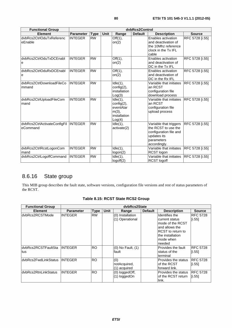
ETSI
ETSI TS 101 545-3 V1.1.1 (2012-05)80
Functional Group dvbRcs2Control Element Parameter Type Unit Range Default Description Source
dvbRcs2CtrlOduTxReferenceEnable
INTEGER RW Off(1), on(2)
Enables activation and deactivation of the 10Mhz reference clock in the Tx IFL cable
RFC 5728 [i.55]
dvbRcs2CtrlOduTxDCEnable
INTEGER RW Off(1), on(2)
Enables activation and deactivation of DC in the Tx IFL
RFC 5728 [i.55]
dvbRcs2CtrlOduRxDCEnable
INTEGER RW Off(1), on(2)
Enables activation and deactivation of DC in the Rx IFL
RFC 5728 [i.55]
dvbRcs2CtrlDownloadFileCommand
INTEGER RW Idle(1), config(2), installationLog(3)
Variable that initiates an RCST configuration file download process
RFC 5728 [i.55]
dvbRcs2CtrlUploadFileCommand
INTEGER RW Idle(1), config(2), eventAlarm(3), installationLog(4)
Variable that initiates an RCST configuration file upload process
RFC 5728 [i.55]
dvbRcs2CtrlActivateConfigFileCommand
INTEGER RW Idle(1), activate(2)
Variable that triggers the RCST to use the configuration file and updates its parameters accordingly.
RFC 5728 [i.55]
dvbRcs2CtrlRcstLogonCommand
INTEGER RW Idle(1), logon(2)
Variable that initiates RCST logon
RFC 5728 [i.55]
dvbRcs2CtrlLogoffCommand INTEGER RW Idle(1), logoff(2)
Variable that initiates RCST logoff
RFC 5728 [i.55]
8.6.16 State group
This MIB group describes the fault state, software versions, configuration file versions and rest of status parameters of the RCST.
Table 8.15: RCST State RCS2 Group
Functional Group dvbRcs2State Element Parameter Type Unit Range Default Description Source
dvbRcs2RCSTMode INTEGER RW (0) Installation (1) Operational
Identifies the current status mode of the RCST and allows the RCST to return to the installation mode when needed
RFC 5728 [i.55]
dvbRcs2RCSTFaultStatus
INTEGER RO (0) No Fault, (1) fault
Provides the fault status of the terminal
RFC 5728 [i.55]
dvbRcs2FwdLinkStatus INTEGER RO (0) notAcquired, (1) acquired
Provides the status of the RCST forward link.
RFC 5728 [i.55]
dvbRcs2RtnLinkStatus INTEGER RO (0) loggedOff, (1) loggedOn
Provides the status of the RCST return link.
RFC 5728 [i.55]
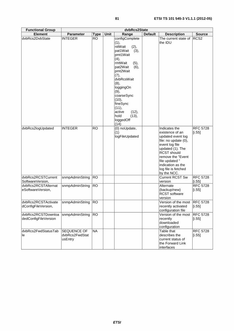
ETSI
ETSI TS 101 545-3 V1.1.1 (2012-05)81
Functional Group dvbRcs2State Element Parameter Type Unit Range Default Description Source
dvbRcs2DvbState INTEGER RO configComplete (1), nitWait (2), pat1Wait (3), pmt1Wait (4), rmtWait (5), pat2Wait (6), pmt2Wait (7), dvbRcsWait (8), loggingOn (9), coarseSync (10), fineSync (11), active (12), hold (13), loggedOff (14)
The current state of the IDU
RCS2
dvbRcs2logUpdated INTEGER RO (0) noUpdate, (1) logFileUpdated
Indicates the existence of an updated event log file: no update (0), event log file updated (1). The RCST should remove the "Event file updated " indication as the log file is fetched by the NCC.
RFC 5728 [i.55]
dvbRcs2RCSTCurrentSoftwareVersion,
snmpAdminString RO Current RCST Sw version
RFC 5728 [i.55]
dvbRcs2RCSTAlternateSoftwareVersion,
snmpAdminString RO Alternate (backup/new) RCST software version
RFC 5728 [i.55]
dvbRcs2RCSTActivatedConfigFileVersion,
snmpAdminString RO Version of the most recently activated configuration file
RFC 5728 [i.55]
dvbRcs2RCSTDownloadedConfigFileVersion
snmpAdminString RO Version of the most recently downloaded configuration
RFC 5728 [i.55]
dvbRcs2FwdStatusTable
SEQUENCE OF dvbRcs2FwdStatusEntry
NA Table that describes the current status of the Forward Link interfaces
RFC 5728 [i.55]
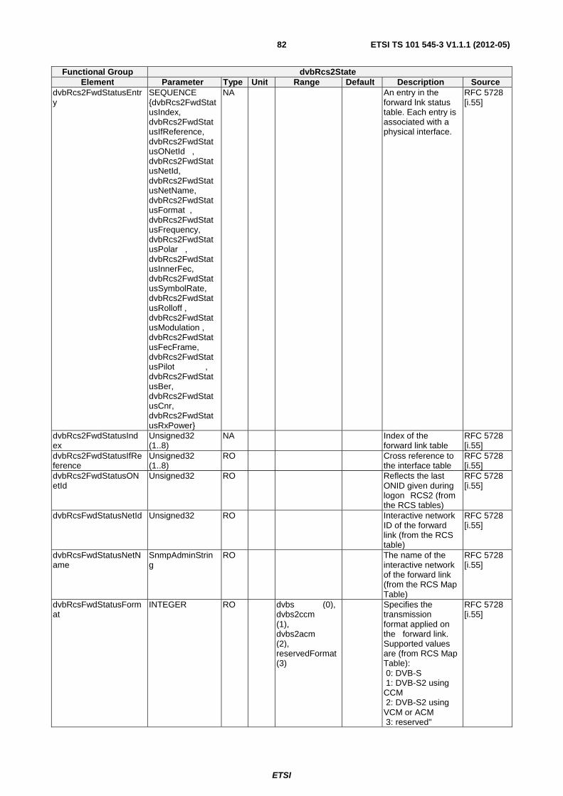
ETSI
ETSI TS 101 545-3 V1.1.1 (2012-05)82
Functional Group dvbRcs2State Element Parameter Type Unit Range Default Description Source
dvbRcs2FwdStatusEntry
SEQUENCE {dvbRcs2FwdStatusIndex, dvbRcs2FwdStatusIfReference, dvbRcs2FwdStatusONetId , dvbRcs2FwdStatusNetId, dvbRcs2FwdStatusNetName, dvbRcs2FwdStatusFormat , dvbRcs2FwdStatusFrequency, dvbRcs2FwdStatusPolar , dvbRcs2FwdStatusInnerFec, dvbRcs2FwdStatusSymbolRate, dvbRcs2FwdStatusRolloff , dvbRcs2FwdStatusModulation , dvbRcs2FwdStatusFecFrame, dvbRcs2FwdStatusPilot , dvbRcs2FwdStatusBer, dvbRcs2FwdStatusCnr, dvbRcs2FwdStatusRxPower}
NA An entry in the forward lnk status table. Each entry is associated with a physical interface.
RFC 5728 [i.55]
dvbRcs2FwdStatusIndex
Unsigned32 (1..8)
NA Index of the forward link table
RFC 5728 [i.55]
dvbRcs2FwdStatusIfReference
Unsigned32 (1..8)
RO Cross reference to the interface table
RFC 5728 [i.55]
dvbRcs2FwdStatusONetId
Unsigned32 RO Reflects the last ONID given during logon RCS2 (from the RCS tables)
RFC 5728 [i.55]
dvbRcsFwdStatusNetId Unsigned32 RO Interactive network ID of the forward link (from the RCS table)
RFC 5728 [i.55]
dvbRcsFwdStatusNetName
SnmpAdminString
RO The name of the interactive network of the forward link (from the RCS Map Table)
RFC 5728 [i.55]
dvbRcsFwdStatusFormat
INTEGER RO dvbs (0), dvbs2ccm (1), dvbs2acm (2), reservedFormat (3)
Specifies the transmission format applied on the forward link. Supported values are (from RCS Map Table): 0: DVB-S 1: DVB-S2 using CCM 2: DVB-S2 using VCM or ACM 3: reserved"
RFC 5728 [i.55]
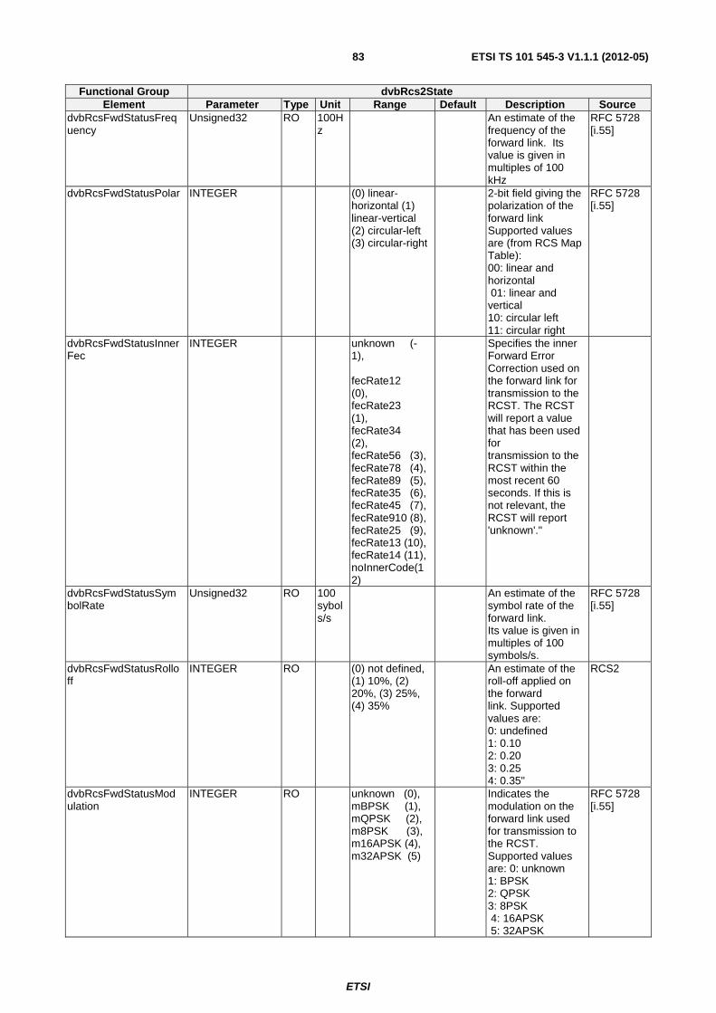
ETSI
ETSI TS 101 545-3 V1.1.1 (2012-05)83
Functional Group dvbRcs2State Element Parameter Type Unit Range Default Description Source
dvbRcsFwdStatusFrequency
Unsigned32 RO 100Hz
An estimate of the frequency of the forward link. Its value is given in multiples of 100 kHz
RFC 5728 [i.55]
dvbRcsFwdStatusPolar
INTEGER (0) linear-horizontal (1) linear-vertical (2) circular-left (3) circular-right
2-bit field giving the polarization of the forward link Supported values are (from RCS Map Table): 00: linear and horizontal 01: linear and vertical 10: circular left 11: circular right
RFC 5728 [i.55]
dvbRcsFwdStatusInnerFec
INTEGER unknown (-1), fecRate12 (0), fecRate23 (1), fecRate34 (2), fecRate56 (3), fecRate78 (4), fecRate89 (5), fecRate35 (6), fecRate45 (7), fecRate910 (8), fecRate25 (9), fecRate13 (10), fecRate14 (11), noInnerCode(12)
Specifies the inner Forward Error Correction used on the forward link for transmission to the RCST. The RCST will report a value that has been used for transmission to the RCST within the most recent 60 seconds. If this is not relevant, the RCST will report 'unknown'."
dvbRcsFwdStatusSymbolRate
Unsigned32 RO 100 sybols/s
An estimate of the symbol rate of the forward link. Its value is given in multiples of 100 symbols/s.
RFC 5728 [i.55]
dvbRcsFwdStatusRolloff
INTEGER RO (0) not defined, (1) 10%, (2) 20%, (3) 25%, (4) 35%
An estimate of the roll-off applied on the forward link. Supported values are: 0: undefined 1: 0.10 2: 0.20 3: 0.25 4: 0.35"
RCS2
dvbRcsFwdStatusModulation
INTEGER RO unknown (0), mBPSK (1), mQPSK (2), m8PSK (3), m16APSK (4), m32APSK (5)
Indicates the modulation on the forward link used for transmission to the RCST. Supported values are: 0: unknown 1: BPSK 2: QPSK 3: 8PSK 4: 16APSK 5: 32APSK
RFC 5728 [i.55]
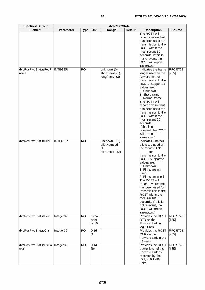
ETSI
ETSI TS 101 545-3 V1.1.1 (2012-05)84
Functional Group dvbRcs2State Element Parameter Type Unit Range Default Description Source
The RCST will report a value that has been used for transmission to the RCST within the most recent 60 seconds. If this is not relevant, the RCST will report 'unknown'."
dvbRcsFwdStatusFecFrame
INTEGER RO unknown (0), shortframe (1), longframe (2)
Indicates the frame length used on the forward link for transmission to the RCST. Supported values are: 0: Unknown 1: Short frame 2: Normal frame The RCST will report a value that has been used for transmission to the RCST within the most recent 60 seconds. If this is not relevant, the RCST will report 'unknown'."
RFC 5728 [i.55]
dvbRcsFwdStatusPilot INTEGER RO unknown (0), pilotNotused (1), pilotUsed (2)
Indicates whether pilots are used on the forward link for transmission to the RCST. Supported values are: 0: Unknown 1: Pilots are not used 2: Pilots are used The RCST will report a value that has been used for transmission to the RCST within the most recent 60 seconds. If this is not relevant, the RCST will report 'unknown'."
dvbRcsFwdStatusBer Integer32 RO Exponent of 10
Provides the RCST BER on the Forward Link in log10units
RFC 5728 [i.55]
dvbRcsFwdStatusCnr Integer32 RO 0.1dB
Provides the RCST CNR on the Forward Link in 0.1 dB units
RFC 5728 [i.55]
dvbRcsFwdStatusRxPower
Integer32 RO 0.1dBm
Provides the RCST power level of the Forward Link as received by the IDU, in 0.1 dBm units
RFC 5728 [i.55]
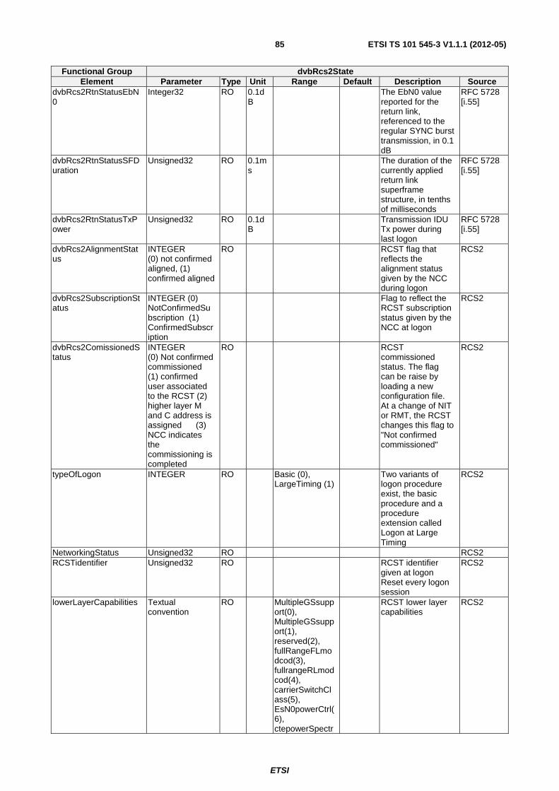
ETSI
ETSI TS 101 545-3 V1.1.1 (2012-05)85
Functional Group dvbRcs2State Element Parameter Type Unit Range Default Description Source
dvbRcs2RtnStatusEbN0
Integer32 RO 0.1dB
The EbN0 value reported for the return link, referenced to the regular SYNC burst transmission, in 0.1 dB
RFC 5728 [i.55]
dvbRcs2RtnStatusSFDuration
Unsigned32 RO 0.1ms
The duration of the currently applied return link superframe structure, in tenths of milliseconds
RFC 5728 [i.55]
dvbRcs2RtnStatusTxPower
Unsigned32 RO 0.1dB
Transmission IDU Tx power during last logon
RFC 5728 [i.55]
dvbRcs2AlignmentStatus
INTEGER (0) not confirmed aligned, (1) confirmed aligned
RO RCST flag that reflects the alignment status given by the NCC during logon
RCS2
dvbRcs2SubscriptionStatus
INTEGER (0) NotConfirmedSubscription (1) ConfirmedSubscription
Flag to reflect the RCST subscription status given by the NCC at logon
RCS2
dvbRcs2ComissionedStatus
INTEGER (0) Not confirmed commissioned (1) confirmed user associated to the RCST (2) higher layer M and C address is assigned (3) NCC indicates the commissioning is completed
RO RCST commissioned status. The flag can be raise by loading a new configuration file. At a change of NIT or RMT, the RCST changes this flag to "Not confirmed commissioned"
RCS2
typeOfLogon INTEGER RO Basic (0), LargeTiming (1)
Two variants of logon procedure exist, the basic procedure and a procedure extension called Logon at Large Timing
RCS2
NetworkingStatus Unsigned32 RO RCS2 RCSTidentifier Unsigned32 RO RCST identifier
given at logon Reset every logon session
RCS2
lowerLayerCapabilities Textual convention
RO MultipleGSsupport(0), MultipleGSsupport(1), reserved(2), fullRangeFLmodcod(3), fullrangeRLmodcod(4), carrierSwitchClass(5), EsN0powerCtrl(6), ctepowerSpectr
RCST lower layer capabilities
RCS2
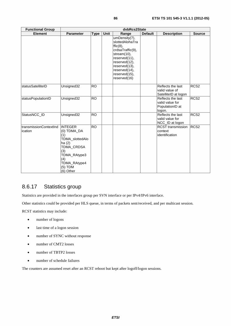
ETSI
ETSI TS 101 545-3 V1.1.1 (2012-05)86
Functional Group dvbRcs2State Element Parameter Type Unit Range Default Description Source
umDensity(7), slottedAlohaTraffic(8), crdsaTraffic(9), stream(10), reserved(11), reserved(12), reserved(13), reserved(14), reserved(15), reserved(16)
statusSatelliteID Unsigned32 RO Reflects the last valid value of SatelliteID at logon
RCS2
statusPopulationID Unsigned32 RO Reflects the last valid value for PopulationID at logon.
RCS2
StatusNCC_ID Unsigned32 RO Reflects the last valid value for NCC_ID at logon
RCS2
transmissionContextIndication
INTEGER (0) TDMA_DA (1) TDMA_slottedAloha (2) TDMA_CRDSA (3) TDMA_RAtype3 (4) TDMA_RAtype4 (5) TDM (6) Other
RO RCST transmission context identification
RCS2
8.6.17 Statistics group
Statistics are provided in the interfaces group per SVN interface or per IPv4/IPv6 interface.
Other statistics could be provided per HLS queue, in terms of packets sent/received, and per multicast session.
RCST statistics may include:
• number of logons
• last time of a logon session
• number of SYNC without response
• number of CMT2 losses
• number of TBTP2 losses
• number of schedule failures
The counters are assumed reset after an RCST reboot but kept after logoff/logon sessions.
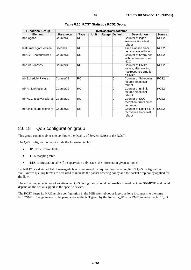
ETSI
ETSI TS 101 545-3 V1.1.1 (2012-05)87
Table 8.16: RCST Statistics RCS2 Group
Functional Group dvbRcs2RcstStatistics Element Parameter Type Unit Range Default Description Source
nbrLogons Counter32 RO 0 Counter of logon sessions since last reboot
RCS2
lastTimeLogonSession Seconds RO 0 Time elapsed since last successful logon
RCS2
nbrSYNCnotanswered Counter32 RO 0 Counter of SYNC sent with no answer from NCC
RCS2
nbrCMT2losses Counter32 RO 0 Counter of CMT2 losses, after waiting maxresponse time for a CMT2
RCS2
nbrSchedulerFailures Counter32 RO 0 Counter of Scheduler failures since last reboot
RCS2
nbrRtnLinkFailures Counter32 RO 0 Counter of rtn link failures since last reboot
RCS2
nbrNCCReceiveFailures Counter32 RO 0 Counter of NCC reception errors since last reboot
RCS2
nbrLinkFailureRecovery Counter32 RO 0 Counter of Link Failure recoveries since last reboot
RCS2
8.6.18 QoS configuration group
This group contains objects to configure the Quality of Service (QoS) of the RCST.
The QoS configuration may include the following tables:
• IP Classification table
• HLS mapping table
• LLS configuration table (for supervision only, saves the information given at logon)
Table 8.17 is a sketched list of managed objects that would be required for managing RCST QoS configuration. Well-known queuing terms are here used to indicate the packet ordering policy and the packet drop policy applied for the flow.
The actual implementation of an attempted QoS configuration could be possible to read back via SNMP/IP, and could depend on the actual support in the specific device.
The RCST keeps its MAC service configuration in the MIB after reboot or logon, as long it connects to the same NCC/NMC. Change in any of the parameters in the NIT given by the Network_ID or in RMT given by the NCC_ID.
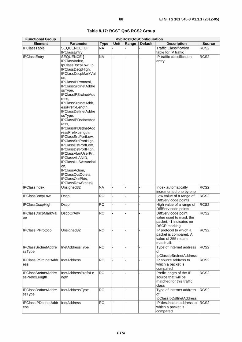
ETSI
ETSI TS 101 545-3 V1.1.1 (2012-05)88
Table 8.17: RCST QoS RCS2 Group
Functional Group dvbRcs2QoSConfiguration Element Parameter Type Unit Range Default Description Source
IPClassTable SEQUENCE OF IPClassEntry
NA - - - Traffic Classification table for IP traffic
RCS2
IPClassEntry SEQUENCE { IPClassIndex, IpClassDscpLow, Ip IPClassDscpHigh, IPClassDscpMarkValue, IPClassIPProtocol, IPClassSrcInetAddressType, IPClassIPSrcInetAddress, IPClassSrcInetAddr,essPrefixLength, IPClassDstInetAddressType, IPClassIPDstInetAddress, IPClassIPDstInetAddressPrefixLength, IPClassSrcPortLow, IPClassSrcPortHigh, IPClassDstPortLow, IPClassDstPortHigh, IPClassVlanUserPri, IPClassVLANID, IPClassHLSAssociation, IPClassAction, IPClassOutOctets, IPClassOutPkts, IPClassRowStatus}
NA - - - IP traffic classification entry
RCS2
IPClassIndex Unsigned32 NA - - - Index automatically incremented one by one
RCS2
IPClassDscpLow Dscp RC - - - Low value of a range of DiffServ code points
RCS2
IPClassDscpHigh Dscp RC - - - High value of a range of DiffServ code points
RCS2
IPClassDscpMarkValue
DscpOrAny RC - - - DiffServ code point value used to mask the packet; -1 indicates no DSCP marking
RCS2
IPClassIPProtocol Unsigned32 RC - - - IP protocol to which a packet is compared. A value of 255 means match all.
RCS2
IPClassSrcInetAddressType
InetAddressType RC - - - Type of Internet address of IpClassIpSrcInetAddress
RCS2
IPClassIPSrcInetAddress
InetAddress RC - - - IP source address to which a packet is compared
RCS2
IPClassSrcInetAddressPrefixLength
InetAddressPrefixLength
RC - - - Prefix length of the IP source that will be matched for this traffic class
RCS2
IPClassDstInetAddressType
InetAddressType RC - - - Type of Internet address of IpClassIpDstInetAddress
RCS2
IPClassIPDstInetAddress
InetAddress RC - - - IP destination address to which a packet is compared
RCS2
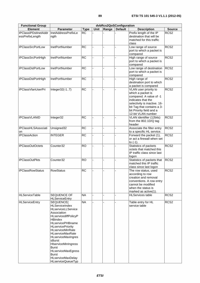
ETSI
ETSI TS 101 545-3 V1.1.1 (2012-05)89
Functional Group dvbRcs2QoSConfiguration Element Parameter Type Unit Range Default Description Source
IPClassIPDstInetAddressPrefixLength
InetAddressPrefixLength
RC - - - Prefix length of the IP destination that will be matched for this traffic class
RCS2
IPClassSrcPortLow InetPortNumber RC - - - Low range of source port to which a packet is compared
RCS2
IPClassSrcPortHigh InetPortNumber RC - - - High range of source port to which a packet is compared
RCS2
IPClassDstPortLow InetPortNumber RC - - - Low range of destination port to which a packet is compared
RCS2
IPClassDstPortHigh InetPortNumber RC - - - High range of destination port to which a packet is compared
RCS2
IPClassVlanUserPri Integer32(-1..7) RC - - - VLAN user priority to which a packet is compared. A value of -1 indicates that the selectivity is inactive. 16-bit Tag that contains a 3-bit Priority field and a 12-bit VLAN number
RCS2
IPClassVLANID Integer32 RC - - - VLAN identifier (12bits) from the 802.1D/Q tag header
RCS2
IPClassHLSAssociation
Unsigned32 RC - - - Associate the filter entry to a specific HL service.
RCS2
IPClassAction INTEGER RC - - - Forward the packet (1), or act a firewall when set to (-1).
RCS2
IPClassOutOctets Counter32 RO - - - Statistics of packets octets that matched this IP traffic class since last logon
RCS2
IPClassOutPkts Counter32 RO - - - Statistics of packets that matched this IP traffic class since last logon
RCS2
IPClassRowStatus RowStatus RC - - - The row status, used according to row creation and removal conventions. A row entry cannot be modified when the status is marked as active(1).
RCS2
HLServiceTable SEQUENCE OF HLServiceEntry
NA - - - HLServices table RCS2
HLServiceEntry SEQUENCE{ HLServiceIndex HLserviceLLServiceAssociation HLservicediffPolicyPHBindex HLservicePHBname HLservicePriority HLserviceMinRate HLserviceMaxRate HLserviceMaxIngressBurst HlserviceMinIngressBurst HLserviceMaxEgressBurst HLserviceMaxDelay HLserviceQueueTyp
NA - - - Table entry for HL service table
RCS2
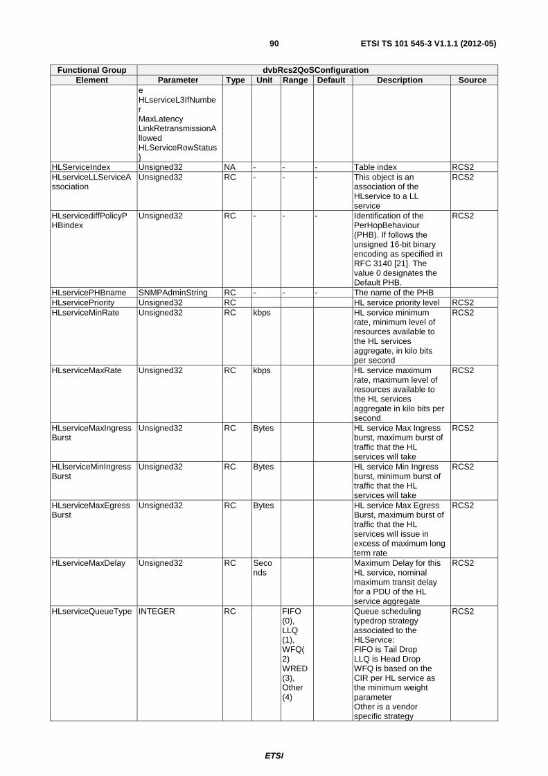
ETSI
ETSI TS 101 545-3 V1.1.1 (2012-05)90
Functional Group dvbRcs2QoSConfiguration Element Parameter Type Unit Range Default Description Source
e HLserviceL3IfNumber MaxLatency LinkRetransmissionAllowed HLServiceRowStatus}
HLServiceIndex Unsigned32 NA - - - Table index RCS2 HLserviceLLServiceAssociation
Unsigned32 RC - - - This object is an association of the HLservice to a LL service
RCS2
HLservicediffPolicyPHBindex
Unsigned32 RC - - - Identification of the PerHopBehaviour (PHB). If follows the unsigned 16-bit binary encoding as specified in RFC 3140 [21]. The value 0 designates the Default PHB.
RCS2
HLservicePHBname SNMPAdminString RC - - - The name of the PHB HLservicePriority Unsigned32 RC HL service priority level RCS2 HLserviceMinRate Unsigned32 RC kbps HL service minimum
rate, minimum level of resources available to the HL services aggregate, in kilo bits per second
RCS2
HLserviceMaxRate Unsigned32 RC kbps HL service maximum rate, maximum level of resources available to the HL services aggregate in kilo bits per second
RCS2
HLserviceMaxIngressBurst
Unsigned32 RC Bytes HL service Max Ingress burst, maximum burst of traffic that the HL services will take
RCS2
HLlserviceMinIngressBurst
Unsigned32 RC Bytes HL service Min Ingress burst, minimum burst of traffic that the HL services will take
RCS2
HLserviceMaxEgressBurst
Unsigned32 RC Bytes HL service Max Egress Burst, maximum burst of traffic that the HL services will issue in excess of maximum long term rate
RCS2
HLserviceMaxDelay Unsigned32 RC Seconds
Maximum Delay for this HL service, nominal maximum transit delay for a PDU of the HL service aggregate
RCS2
HLserviceQueueType INTEGER RC FIFO (0), LLQ (1), WFQ(2) WRED (3), Other (4)
Queue scheduling typedrop strategy associated to the HLService: FIFO is Tail Drop LLQ is Head Drop WFQ is based on the CIR per HL service as the minimum weight parameter Other is a vendor specific strategy
RCS2
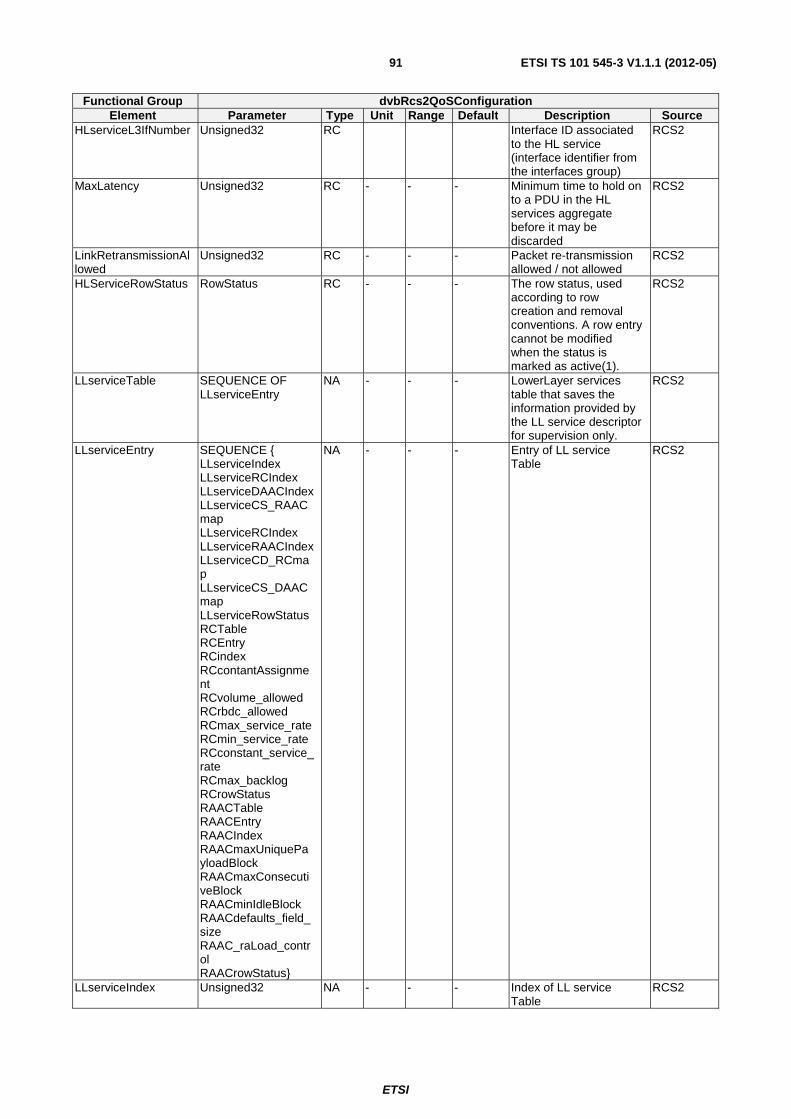
ETSI
ETSI TS 101 545-3 V1.1.1 (2012-05)91
Functional Group dvbRcs2QoSConfiguration Element Parameter Type Unit Range Default Description Source
HLserviceL3IfNumber Unsigned32 RC Interface ID associated to the HL service (interface identifier from the interfaces group)
RCS2
MaxLatency Unsigned32 RC - - - Minimum time to hold on to a PDU in the HL services aggregate before it may be discarded
RCS2
LinkRetransmissionAllowed
Unsigned32 RC - - - Packet re-transmission allowed / not allowed
RCS2
HLServiceRowStatus RowStatus RC - - - The row status, used according to row creation and removal conventions. A row entry cannot be modified when the status is marked as active(1).
RCS2
LLserviceTable SEQUENCE OF LLserviceEntry
NA - - - LowerLayer services table that saves the information provided by the LL service descriptor for supervision only.
RCS2
LLserviceEntry SEQUENCE { LLserviceIndex LLserviceRCIndex LLserviceDAACIndex LLserviceCS_RAACmap LLserviceRCIndex LLserviceRAACIndex LLserviceCD_RCmap LLserviceCS_DAACmap LLserviceRowStatus RCTable RCEntry RCindex RCcontantAssignment RCvolume_allowed RCrbdc_allowed RCmax_service_rate RCmin_service_rate RCconstant_service_rate RCmax_backlog RCrowStatus RAACTable RAACEntry RAACIndex RAACmaxUniquePayloadBlock RAACmaxConsecutiveBlock RAACminIdleBlock RAACdefaults_field_size RAAC_raLoad_control RAACrowStatus}
NA - - - Entry of LL service Table
RCS2
LLserviceIndex Unsigned32 NA - - - Index of LL service Table
RCS2
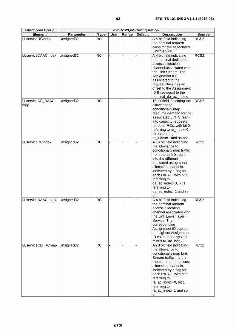
ETSI
ETSI TS 101 545-3 V1.1.1 (2012-05)92
Functional Group dvbRcs2QoSConfiguration Element Parameter Type Unit Range Default Description Source
LLserviceRCIndex Unsigned32 RC - - - A 4 bit field indicating the nominal request class for the associated Link Service.
RCS2
LLserviceDAACIndex Unsigned32 RC - - - A 4 bit field indicating the nominal dedicated access allocation channel associated with the Link Stream. The Assignment ID associated to the request class has an offset to the Assignment ID Base equal to the nominal_da_ac_index;
RCS2
LLserviceCS_RAACmap
Unsigned32 RC - - - 16 bit field indicating the allowance to conditionally map resource demand for the associated Link Stream into capacity requests for other RCs, with bit 0 referring to rc_index=0, bit 1 referring to rc_index=1 and so on;
RCS2
LLserviceRCIndex Unsigned32 RC - - - A 16 bit field indicating the allowance to conditionally map traffic from the Link Stream into the different dedicated assignment allocation channels, indicated by a flag for each DA-AC, with bit 0 referring to da_ac_index=0, bit 1 referring to da_ac_index=1 and so on.
RCS2
LLserviceRAACIndex Unsigned32 RC - - - A 4 bit field indicating the nominal random access allocation channel associated with the Link Lower layer Service. The corresponding Assignment ID equals the highest Assignment ID value in the system minus ra_ac_index
RCS2
LLserviceCD_RCmap Unsigned32 RC - - - An 8 bit field indicating the allowance to conditionally map Link Stream traffic into the different random access allocation channels, indicated by a flag for each RA-AC, with bit 0 referring to ra_ac_index=0, bit 1 referring to ra_ac_index=1 and so on.
RCS2
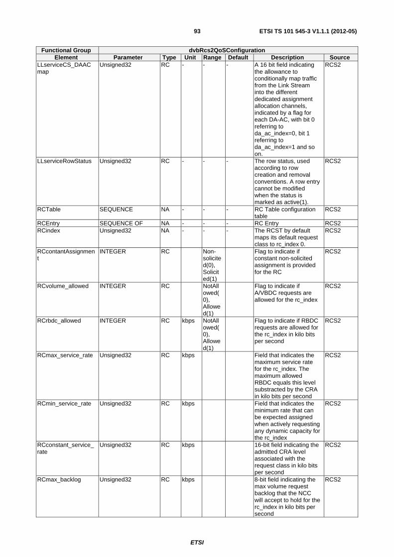
ETSI
ETSI TS 101 545-3 V1.1.1 (2012-05)93
Functional Group dvbRcs2QoSConfiguration Element Parameter Type Unit Range Default Description Source
LLserviceCS_DAACmap
Unsigned32 RC - - - A 16 bit field indicating the allowance to conditionally map traffic from the Link Stream into the different dedicated assignment allocation channels, indicated by a flag for each DA-AC, with bit 0 referring to da_ac_index=0, bit 1 referring to da_ac_index=1 and so on.
RCS2
LLserviceRowStatus Unsigned32 RC - - - The row status, used according to row creation and removal conventions. A row entry cannot be modified when the status is marked as active(1).
RCS2
RCTable SEQUENCE NA - - - RC Table configuration table
RCS2
RCEntry SEQUENCE OF NA - - - RC Entry RCS2 RCindex Unsigned32 NA - - - The RCST by default
maps its default request class to rc_index 0.
RCS2
RCcontantAssignment
INTEGER RC Non-solicited(0), Solicited(1)
Flag to indicate if constant non-solicited assignment is provided for the RC
RCS2
RCvolume_allowed INTEGER RC NotAllowed(0), Allowed(1)
Flag to indicate if A/VBDC requests are allowed for the rc_index
RCS2
RCrbdc_allowed INTEGER RC kbps NotAllowed(0), Allowed(1)
Flag to indicate if RBDC requests are allowed for the rc_index in kilo bits per second
RCS2
RCmax_service_rate Unsigned32 RC kbps Field that indicates the maximum service rate for the rc_index. The maximum allowed RBDC equals this level substracted by the CRA in kilo bits per second
RCS2
RCmin_service_rate Unsigned32 RC kbps Field that indicates the minimum rate that can be expected assigned when actively requesting any dynamic capacity for the rc_index
RCS2
RCconstant_service_rate
Unsigned32 RC kbps 16-bit field indicating the admitted CRA level associated with the request class in kilo bits per second
RCS2
RCmax_backlog Unsigned32 RC kbps 8-bit field indicating the max volume request backlog that the NCC will accept to hold for the rc_index in kilo bits per second
RCS2
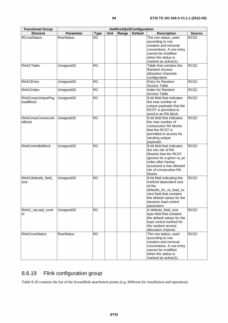
ETSI
ETSI TS 101 545-3 V1.1.1 (2012-05)94
Functional Group dvbRcs2QoSConfiguration Element Parameter Type Unit Range Default Description Source
RCrowStatus RowStatus RC The row status, used according to row creation and removal conventions. A row entry cannot be modified when the status is marked as active(1).
RCS2
RAACTable Unsigned32 RC Table that contains the Random Access allocation channels configuration
RCS2
RAACEntry Unsigned32 RC Entry for Random Access Table
RCS2
RAACIndex Unsigned32 RC Index for Random Access Table
RCS2
RAACmaxUniquePayloadBlock
Unsigned32 RC 8-bit field that indicates the max number of unique payloads that the RCST is permitted to send in an RA block
RCS2
RAACmaxConsecutiveBlock
Unsigned32 RC 8-bit field that indicates the max number of consecutive RA blocks that the RCST is permitted to access for sending unique payloads
RCS2
RAACminIdleBlock Unsigned32 RC 8-bit field that indicates the min nbr of RA bloacks that the RCST ignores for a given ra_ac index after having accessed a max allowed nbr of consecutive RA blocks
RCS2
RAACdefaults_field_size
Unsigned32 RC 8-bit field indicating the method dependent size of the defaults_for_ra_load_control field that contains the default values for the dynamic load control parameers
RCS2
RAAC_raLoad_control
Unsigned32 RC A defauts_field_size byte field that contains the default values for the load control method for the random access allocation channel.
RCS2
RAACrowStatus RowStatus RC The row status, used according to row creation and removal conventions. A row entry cannot be modified when the status is marked as active(1).
RCS2
8.6.19 Flink configuration group
Table 8.18 contains the list of the fowardlink attachment points (e.g. different for installation and operation).
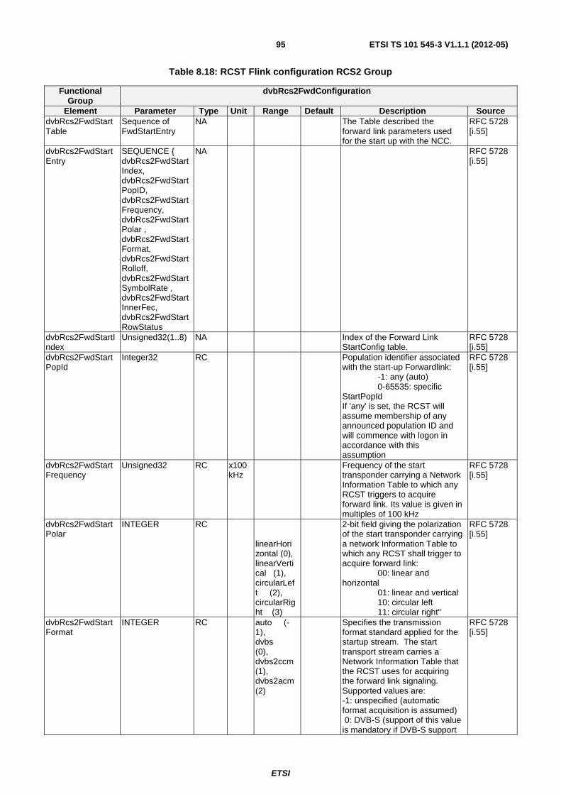
ETSI
ETSI TS 101 545-3 V1.1.1 (2012-05)95
Table 8.18: RCST Flink configuration RCS2 Group
Functional Group
dvbRcs2FwdConfiguration
Element Parameter Type Unit Range Default Description Source dvbRcs2FwdStartTable
Sequence of FwdStartEntry
NA The Table described the forward link parameters used for the start up with the NCC.
RFC 5728 [i.55]
dvbRcs2FwdStartEntry
SEQUENCE { dvbRcs2FwdStartIndex, dvbRcs2FwdStartPopID, dvbRcs2FwdStartFrequency, dvbRcs2FwdStartPolar , dvbRcs2FwdStartFormat, dvbRcs2FwdStartRolloff, dvbRcs2FwdStartSymbolRate , dvbRcs2FwdStartInnerFec, dvbRcs2FwdStartRowStatus
NA RFC 5728 [i.55]
dvbRcs2FwdStartIndex
Unsigned32(1..8) NA Index of the Forward Link StartConfig table.
RFC 5728 [i.55]
dvbRcs2FwdStartPopId
Integer32 RC Population identifier associated with the start-up Forwardlink: -1: any (auto) 0-65535: specific StartPopId If 'any' is set, the RCST will assume membership of any announced population ID and will commence with logon in accordance with this assumption
RFC 5728 [i.55]
dvbRcs2FwdStartFrequency
Unsigned32 RC x100 kHz
Frequency of the start transponder carrying a Network Information Table to which any RCST triggers to acquire forward link. Its value is given in multiples of 100 kHz
RFC 5728 [i.55]
dvbRcs2FwdStartPolar
INTEGER RC linearHorizontal (0), linearVertical (1), circularLeft (2), circularRight (3)
2-bit field giving the polarization of the start transponder carrying a network Information Table to which any RCST shall trigger to acquire forward link: 00: linear and horizontal 01: linear and vertical 10: circular left 11: circular right"
RFC 5728 [i.55]
dvbRcs2FwdStartFormat
INTEGER RC auto (-1), dvbs (0), dvbs2ccm (1), dvbs2acm (2)
Specifies the transmission format standard applied for the startup stream. The start transport stream carries a Network Information Table that the RCST uses for acquiring the forward link signaling. Supported values are: -1: unspecified (automatic format acquisition is assumed) 0: DVB-S (support of this value is mandatory if DVB-S support
RFC 5728 [i.55]
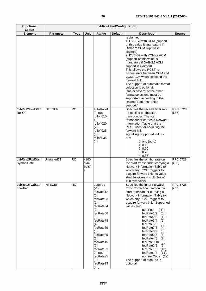
ETSI
ETSI TS 101 545-3 V1.1.1 (2012-05)96
Functional Group
dvbRcs2FwdConfiguration
Element Parameter Type Unit Range Default Description Source is claimed) 1: DVB-S2 with CCM (support of this value is mandatory if DVB-S2 CCM support is claimed) 2: DVB-S2 with VCM or ACM (support of this value is mandatory if DVB-S2 ACM support is claimed) This allows the RCST to discriminate between CCM and VCM/ACM when selecting the forward link. The support of automatic format selection is optional. One or several of the other format selections must be supported, according to the claimed SatLabs profile support."
dvbRcs2FwdStartRollOff
INTEGER RC autoRolloff (0), rolloff010,(1) rolloff020 (2), rolloff025 (3), rolloff035 (4)
Specifies the receive filter roll-off applied on the start transponder. The start transponder carries a Network Information Table that the RCST uses for acquiring the forward link signalling.Supported values are: 0: any (auto) 1: 0.10 2: 0.20 3: 0.25 4: 0.35"
RFC 5728 [i.55]
dvbRcs2FwdStartSymbolRate
Unsigned32 RC x100 symbols/s
Specifies the symbol rate on the start transponder carrying a Network Information Table to which any RCST triggers to acquire forward link. Its value shall be given in multiples of 100 symbols/s
RFC 5728 [i.55]
dvbRcs2FwdStartInnerFec
INTEGER RC autoFec (-1), fecRate12 (0), fecRate23 (1), fecRate34 (2), fecRate56 (3), fecRate78 (4), fecRate89 (5), fecRate35 (6), fecRate45 (7), fecRate910 (8), fecRate25 (9), fecRate13 (10),
Specifies the inner Forward Error Correction used on the start transponder carrying a Network Information Table to which any RCST triggers to acquire forward link. Supported values are: autoFec (-1), fecRate1/2 (0), fecRate2/3 (1), fecRate3/4 (2), fecRate5/6 (3), fecRate7/8 (4), fecRate8/9 (5), fecRate3/5 (6), fecRate4/5 (7), fecRate9/10 (8), fecRate2/5 (9), fecRate1/3 (10), fecRate1/4 (11), noInnerCode (12) The support of autoFec is optional
RFC 5728 [i.55]
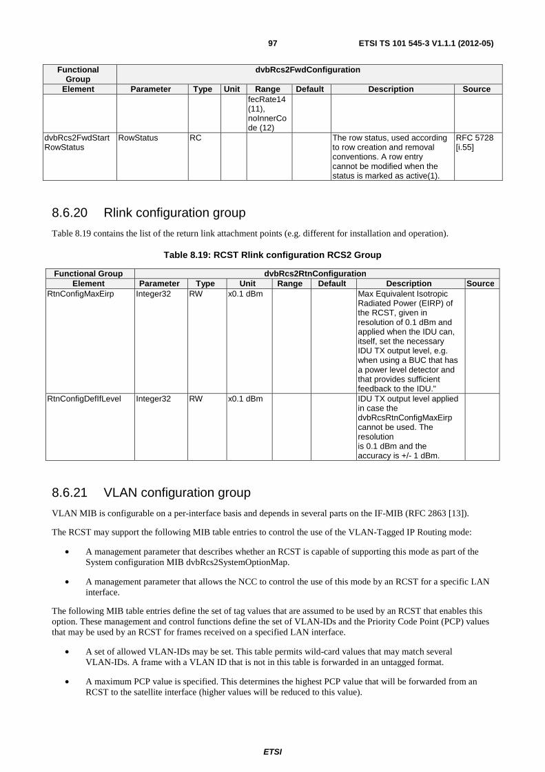
ETSI
ETSI TS 101 545-3 V1.1.1 (2012-05)97
Functional Group
dvbRcs2FwdConfiguration
Element Parameter Type Unit Range Default Description Source fecRate14 (11), noInnerCode (12)
dvbRcs2FwdStartRowStatus
RowStatus RC The row status, used according to row creation and removal conventions. A row entry cannot be modified when the status is marked as active(1).
RFC 5728 [i.55]
8.6.20 Rlink configuration group
Table 8.19 contains the list of the return link attachment points (e.g. different for installation and operation).
Table 8.19: RCST Rlink configuration RCS2 Group
Functional Group dvbRcs2RtnConfiguration Element Parameter Type Unit Range Default Description Source
RtnConfigMaxEirp Integer32 RW x0.1 dBm Max Equivalent Isotropic Radiated Power (EIRP) of the RCST, given in resolution of 0.1 dBm and applied when the IDU can, itself, set the necessary IDU TX output level, e.g. when using a BUC that has a power level detector and that provides sufficient feedback to the IDU."
RtnConfigDefIfLevel Integer32 RW x0.1 dBm IDU TX output level applied in case the dvbRcsRtnConfigMaxEirp cannot be used. The resolution is 0.1 dBm and the accuracy is +/- 1 dBm.
8.6.21 VLAN configuration group
VLAN MIB is configurable on a per-interface basis and depends in several parts on the IF-MIB (RFC 2863 [13]).
The RCST may support the following MIB table entries to control the use of the VLAN-Tagged IP Routing mode:
• A management parameter that describes whether an RCST is capable of supporting this mode as part of the System configuration MIB dvbRcs2SystemOptionMap.
• A management parameter that allows the NCC to control the use of this mode by an RCST for a specific LAN interface.
The following MIB table entries define the set of tag values that are assumed to be used by an RCST that enables this option. These management and control functions define the set of VLAN-IDs and the Priority Code Point (PCP) values that may be used by an RCST for frames received on a specified LAN interface.
• A set of allowed VLAN-IDs may be set. This table permits wild-card values that may match several VLAN-IDs. A frame with a VLAN ID that is not in this table is forwarded in an untagged format.
• A maximum PCP value is specified. This determines the highest PCP value that will be forwarded from an RCST to the satellite interface (higher values will be reduced to this value).
ETSI
ETSI TS 101 545-3 V1.1.1 (2012-05)98
8.6.22 NAT/NAPT configuration group
NAT MIB is configurable on a per-interface basis and depends in several parts on the IF-MIB (RFC 2863 [13]).
NAT MIB is defined in (RFC 4008 [i.89]) and NAPT variants in (RFC 3489 [i.82])
The RCST may implement the natInterfaceTable MIB module from (RFC 4008 [i.89]) to configure interface specific realm type and the NAT services enabled for the interface. natInterfaceTable is indexed by ifIndex and also includes interface specific NAT statistics.
The RCST may implement natAddrMapTable MIB module from (RFC 4008 [i.89]) to configure address maps on a per-interface basis.
The RCST may implement two Bind tables, natAddrBindTable and natAddrPortBindTable from (RFC 4008 [i.89]), defined to hold the bind entries. Entries are derived from the address map table and are not configurable.
The RCST may implement the natSessionTable defined to hold NAT session entries.
The RCST NAT/NAPT function may be configurable per enabled interface, including the following parameters:
• NAT enable/disable flag. By default NAT may be disabled.
• Global and Local addresses.
• Static NAPT UDP/TCP port translation range.
• Dynamic NAPT UDP/TCP port translation range.
8.6.23 PEP negotiation configuration
The PEP negotiation group compiles all the necessary information to perform PEP negotiation between the RCST and the NCC.
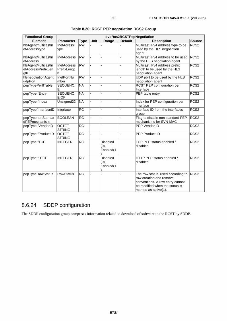
ETSI
ETSI TS 101 545-3 V1.1.1 (2012-05)99
Table 8.20: RCST PEP negotiation RCS2 Group
Functional Group dvbRcs2RCSTPepNegotiation Element Parameter Type Unit Range Default Description Source
hlsAgentmulticastInetAddresstype
InetAdressType
RW - - - Multicast IPv4 address type to be used by the HLS negotiation agent
RCS2
hlsAgentMulticastInetAddress
InetAddress RW - - - Multicast IPv4 address to be used by the HLS negotiation agent
RCS2
hlsAgentMulticastInetAddressPrefixLength
InetAddressPrefixLength
RW - - - Multicast IPv4 address prefix length to be used by the HLS negotiation agent
RCS2
hlsnegotiationAgentudpPort
InetPortNumber
RW - - - UDP port to be used by the HLS negotiation agent
RCS2
pepTypePerIfTable SEQUENCE
NA - - - RCST PEP configuration per Interface
RCS2
pepTypeIfEntry SEQUENCE OF
NA - - - PEP table entry RCS2
pepTypeIfIndex Unsigned32 NA - - - Index for PEP configuration per interface
RCS2
pepTypefInterfaceID Interface RC - - - Interface ID from the interfaces group
RCS2
pepTypenonStandardPEPmechanism
BOOLEAN RC - - - Flag to disable non standard PEP mechanisms for SVN-MAC
RCS2
pepTypeIfVendorID OCTET STRING
RC - - - PEP Vendor ID RCS2
pepTypeIfProductID OCTET STRING
RC - - - PEP Product ID RCS2
pepTypeIfTCP INTEGER RC Disabled (0), Enabled(1)
TCP PEP status enabled / disabled
RCS2
pepTypeIfHTTP INTEGER RC Disabled (0), Enabled(1)
HTTP PEP status enabled / disabled
RCS2
pepTypeRowStatus RowStatus RC - - - The row status, used according to row creation and removal conventions. A row entry cannot be modified when the status is marked as active(1).
RCS2
8.6.24 SDDP configuration
The SDDP configuration group comprises information related to download of software to the RCST by SDDP.
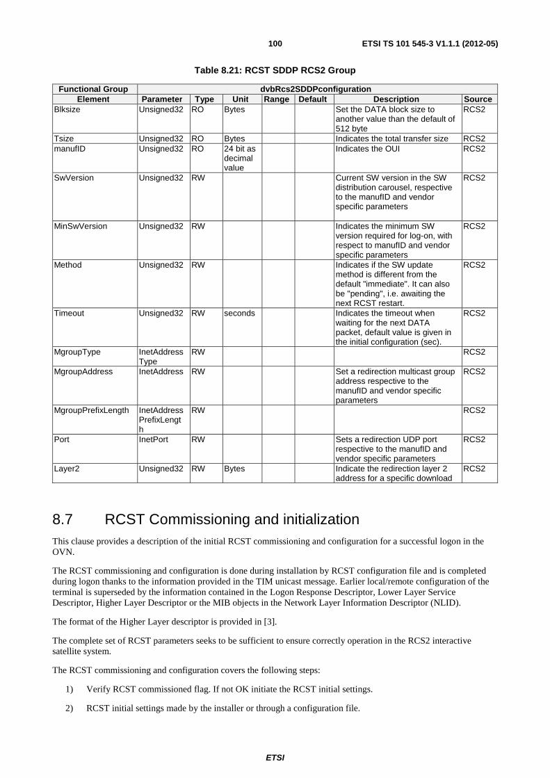
ETSI
ETSI TS 101 545-3 V1.1.1 (2012-05)100
Table 8.21: RCST SDDP RCS2 Group
Functional Group dvbRcs2SDDPconfiguration Element Parameter Type Unit Range Default Description Source
Blksize Unsigned32 RO Bytes Set the DATA block size to another value than the default of 512 byte
RCS2
Tsize Unsigned32 RO Bytes Indicates the total transfer size RCS2 manufID Unsigned32 RO 24 bit as
decimal value
Indicates the OUI RCS2
SwVersion Unsigned32 RW Current SW version in the SW distribution carousel, respective to the manufID and vendor specific parameters
RCS2
MinSwVersion Unsigned32 RW Indicates the minimum SW version required for log-on, with respect to manufID and vendor specific parameters
RCS2
Method Unsigned32 RW Indicates if the SW update method is different from the default "immediate". It can also be "pending", i.e. awaiting the next RCST restart.
RCS2
Timeout Unsigned32 RW seconds Indicates the timeout when waiting for the next DATA packet, default value is given in the initial configuration (sec).
RCS2
MgroupType InetAddressType
RW RCS2
MgroupAddress InetAddress RW Set a redirection multicast group address respective to the manufID and vendor specific parameters
RCS2
MgroupPrefixLength InetAddressPrefixLength
RW RCS2
Port InetPort RW Sets a redirection UDP port respective to the manufID and vendor specific parameters
RCS2
Layer2 Unsigned32 RW Bytes Indicate the redirection layer 2 address for a specific download
RCS2
8.7 RCST Commissioning and initialization This clause provides a description of the initial RCST commissioning and configuration for a successful logon in the OVN.
The RCST commissioning and configuration is done during installation by RCST configuration file and is completed during logon thanks to the information provided in the TIM unicast message. Earlier local/remote configuration of the terminal is superseded by the information contained in the Logon Response Descriptor, Lower Layer Service Descriptor, Higher Layer Descriptor or the MIB objects in the Network Layer Information Descriptor (NLID).
The format of the Higher Layer descriptor is provided in [3].
The complete set of RCST parameters seeks to be sufficient to ensure correctly operation in the RCS2 interactive satellite system.
The RCST commissioning and configuration covers the following steps:
1) Verify RCST commissioned flag. If not OK initiate the RCST initial settings.
2) RCST initial settings made by the installer or through a configuration file.
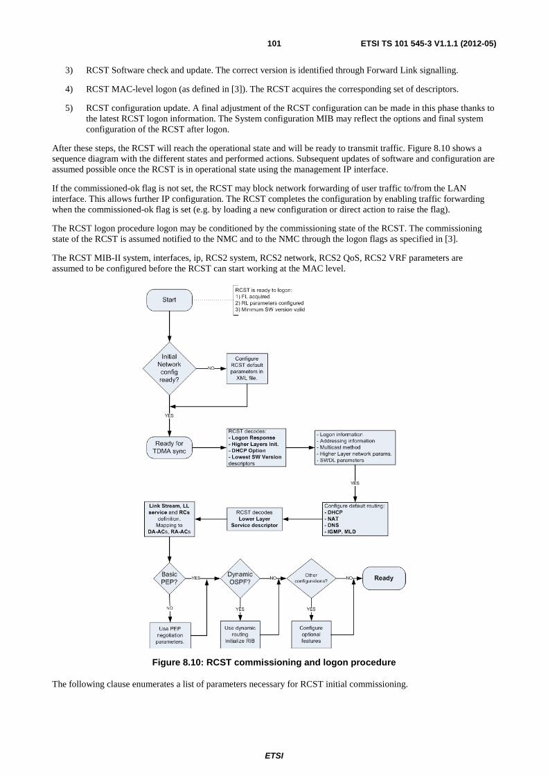
ETSI
ETSI TS 101 545-3 V1.1.1 (2012-05)101
3) RCST Software check and update. The correct version is identified through Forward Link signalling.
4) RCST MAC-level logon (as defined in [3]). The RCST acquires the corresponding set of descriptors.
5) RCST configuration update. A final adjustment of the RCST configuration can be made in this phase thanks to the latest RCST logon information. The System configuration MIB may reflect the options and final system configuration of the RCST after logon.
After these steps, the RCST will reach the operational state and will be ready to transmit traffic. Figure 8.10 shows a sequence diagram with the different states and performed actions. Subsequent updates of software and configuration are assumed possible once the RCST is in operational state using the management IP interface.
If the commissioned-ok flag is not set, the RCST may block network forwarding of user traffic to/from the LAN interface. This allows further IP configuration. The RCST completes the configuration by enabling traffic forwarding when the commissioned-ok flag is set (e.g. by loading a new configuration or direct action to raise the flag).
The RCST logon procedure logon may be conditioned by the commissioning state of the RCST. The commissioning state of the RCST is assumed notified to the NMC and to the NMC through the logon flags as specified in [3].
The RCST MIB-II system, interfaces, ip, RCS2 system, RCS2 network, RCS2 QoS, RCS2 VRF parameters are assumed to be configured before the RCST can start working at the MAC level.
Figure 8.10: RCST commissioning and logon procedure
The following clause enumerates a list of parameters necessary for RCST initial commissioning.
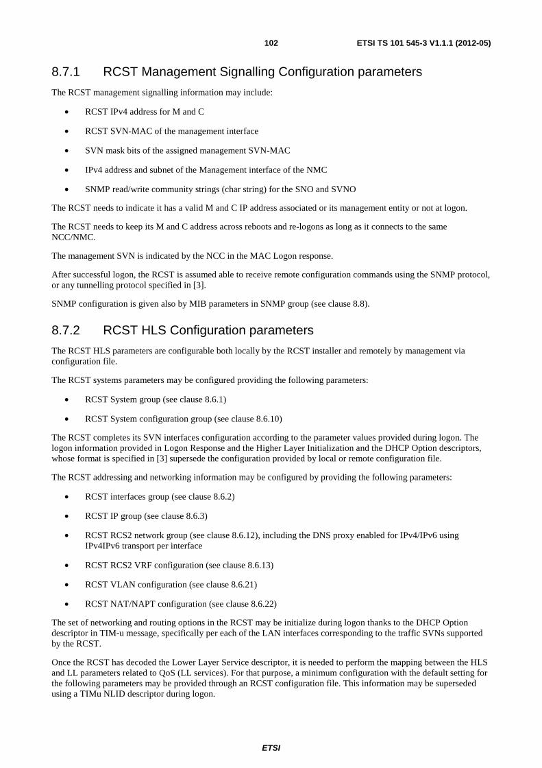
ETSI
ETSI TS 101 545-3 V1.1.1 (2012-05)102
8.7.1 RCST Management Signalling Configuration parameters
The RCST management signalling information may include:
• RCST IPv4 address for M and C
• RCST SVN-MAC of the management interface
• SVN mask bits of the assigned management SVN-MAC
• IPv4 address and subnet of the Management interface of the NMC
• SNMP read/write community strings (char string) for the SNO and SVNO
The RCST needs to indicate it has a valid M and C IP address associated or its management entity or not at logon.
The RCST needs to keep its M and C address across reboots and re-logons as long as it connects to the same NCC/NMC.
The management SVN is indicated by the NCC in the MAC Logon response.
After successful logon, the RCST is assumed able to receive remote configuration commands using the SNMP protocol, or any tunnelling protocol specified in [3].
SNMP configuration is given also by MIB parameters in SNMP group (see clause 8.8).
8.7.2 RCST HLS Configuration parameters
The RCST HLS parameters are configurable both locally by the RCST installer and remotely by management via configuration file.
The RCST systems parameters may be configured providing the following parameters:
• RCST System group (see clause 8.6.1)
• RCST System configuration group (see clause 8.6.10)
The RCST completes its SVN interfaces configuration according to the parameter values provided during logon. The logon information provided in Logon Response and the Higher Layer Initialization and the DHCP Option descriptors, whose format is specified in [3] supersede the configuration provided by local or remote configuration file.
The RCST addressing and networking information may be configured by providing the following parameters:
• RCST interfaces group (see clause 8.6.2)
• RCST IP group (see clause 8.6.3)
• RCST RCS2 network group (see clause 8.6.12), including the DNS proxy enabled for IPv4/IPv6 using IPv4IPv6 transport per interface
• RCST RCS2 VRF configuration (see clause 8.6.13)
• RCST VLAN configuration (see clause 8.6.21)
• RCST NAT/NAPT configuration (see clause 8.6.22)
The set of networking and routing options in the RCST may be initialize during logon thanks to the DHCP Option descriptor in TIM-u message, specifically per each of the LAN interfaces corresponding to the traffic SVNs supported by the RCST.
Once the RCST has decoded the Lower Layer Service descriptor, it is needed to perform the mapping between the HLS and LL parameters related to QoS (LL services). For that purpose, a minimum configuration with the default setting for the following parameters may be provided through an RCST configuration file. This information may be superseded using a TIMu NLID descriptor during logon.
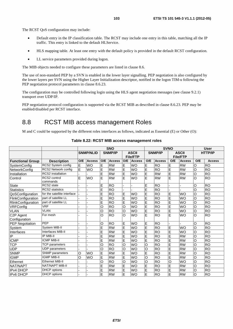
ETSI
ETSI TS 101 545-3 V1.1.1 (2012-05)103
The RCST QoS configuration may include:
• Default entry in the IP classification table. The RCST may include one entry in this table, matching all the IP traffic. This entry is linked to the default HLService.
• HLS mapping table. At least one entry with the default policy is provided in the default RCST configuration.
• LL service parameters provided during logon.
The MIB objects needed to configure these parameters are listed in clause 8.6.
The use of non-standard PEP by a SVN is enabled in the lower layer signalling. PEP negotiation is also configured by the lower layers per SVN using the Higher Layer Initialization descriptor, notified in the logon TIM-u following the PEP negotiation protocol parameters in clause 8.6.23.
The configuration may be controlled following login using the HLS agent negotiation messages (see clause 9.2.1) transport over UDP/IP.
PEP negotiation protocol configuration is supported via the RCST MIB as described in clause 8.6.23. PEP may be enabled/disabled per RCST interface.
8.8 RCST MIB access management Roles M and C could be supported by the different roles interfaces as follows, indicated as Essential (E) or Other (O):
Table 8.22: RCST MIB access management roles
SNO SVNO User SNMP/NLID SNMP/IP ASCII
File/FTP SNMP/IP ASCII
File/FTP HTTP/IP
Functional Group Description O/E Access O/E Access O/E Access O/E Access O/E Access O/E Access
SystemConfig RCS2 System config E WO E RW E WO E RO E RW O RO NetworkConfig RCS2 Network config E WO E RW E WO E RO E RW O RO Installation RCS2 installation - - E RW E WO E RW E RW O RO Control RCS2 control
commands E WO E RW E WO E RW E RW O RO
State RCS2 state - - E RO - - E RO - - O RO Statistics RCS2 statistics - - E RO - - E RO - - O RO QoSConfiguration for the satellite interface - - E RO E WO E RO E WO O RO FlinkConfiguration part of satellite LL - - E RO E WO E RO E WO O RO RlinkConfiguration part of satellite LL - - E RO E WO E RO E WO O RO VRFConfig VRF - - O RO O WO E RO E WO O RO VLAN VLAN - - O RO O WO E RO E WO O RO C2P Agent Configuration
For mesh - - O RO O WO E RO E WO O RO
PEP Negotiation PEP - - O RO E WO E RO - - O RO System System MIB-II - - E RW E WO E RO E WO O RO Interfaces Interfaces MIB-II - - E RW E WO E RO E WO O RO IP IP MIB-II - - E RW E WO E RO E RW O RO ICMP ICMP MIB-II - - E RW E WO E RO E RW O RO TCP TCP parameters - - O RO O WO O RO E RW O RO UDP UDP parameters - - O RO O WO O RO E RW O RO SNMP SNMP parameters O WO E RW E WO E RO E RW O RO IGMP IGMP MIB-II O WO E RW E WO O RO E RW O RO Ethernet Ethernet MIB-II - - O RO O WO O RO O WO O RO NAT/NAPT NAT/NAPT MIB-II - - E RW E WO E RO E RW O RO IPv4 DHCP DHCP options - - E RW E WO E RO E RW O RO IPv6 DHCP DHCP options - - E RW E WO E RO E RW O RO
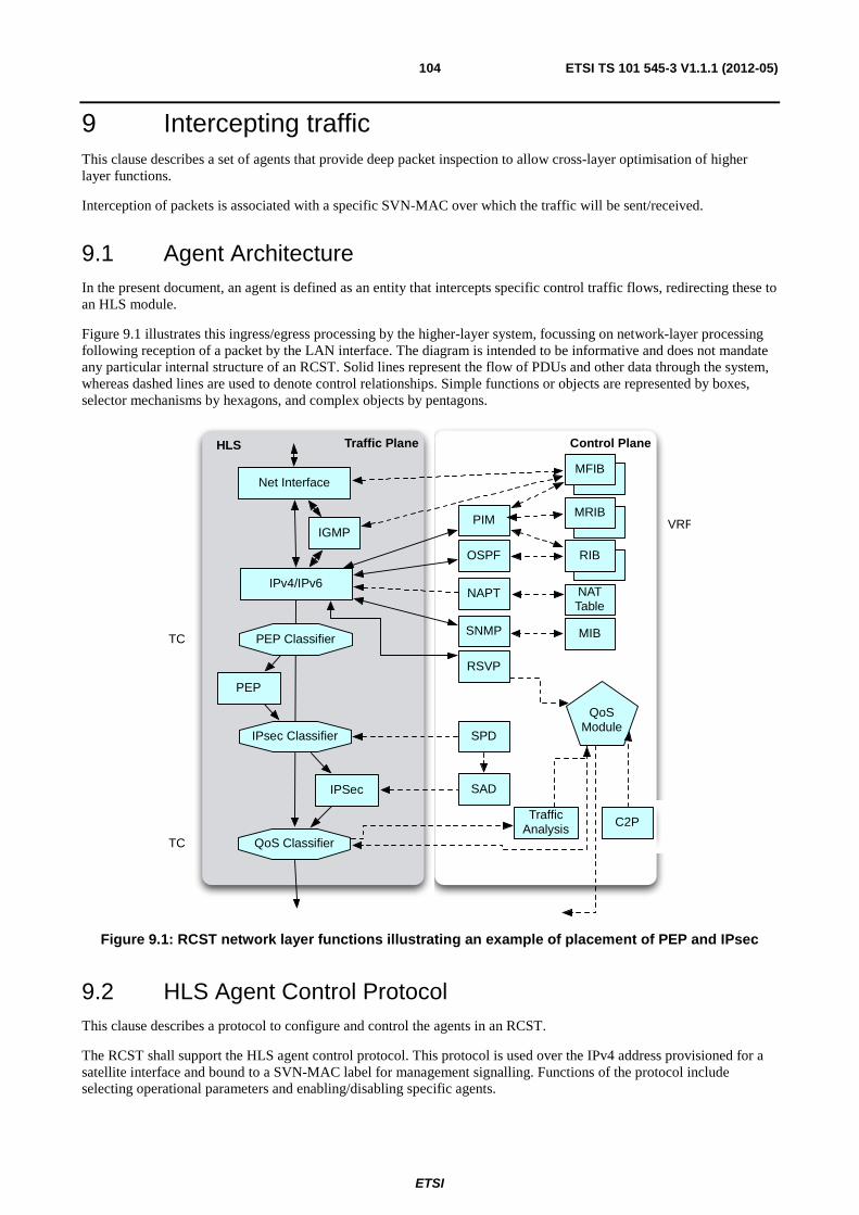
ETSI
ETSI TS 101 545-3 V1.1.1 (2012-05)104
9 Intercepting traffic This clause describes a set of agents that provide deep packet inspection to allow cross-layer optimisation of higher layer functions.
Interception of packets is associated with a specific SVN-MAC over which the traffic will be sent/received.
9.1 Agent Architecture In the present document, an agent is defined as an entity that intercepts specific control traffic flows, redirecting these to an HLS module.
Figure 9.1 illustrates this ingress/egress processing by the higher-layer system, focussing on network-layer processing following reception of a packet by the LAN interface. The diagram is intended to be informative and does not mandate any particular internal structure of an RCST. Solid lines represent the flow of PDUs and other data through the system, whereas dashed lines are used to denote control relationships. Simple functions or objects are represented by boxes, selector mechanisms by hexagons, and complex objects by pentagons.
MFIB
RIB
MRIB
IPv4/IPv6
QoS Classifier
IGMP
QoSModule
TrafficAnalysis
RSVP
HLS Control PlaneTraffic Plane
PEP Classifier
PEP
Net Interface
NAPT
OSPF
PIM
IPsec Classifier
IPSec
SPD
SAD
MFIB
RIB
MRIB
SNMP MIB
VRF
TC
TC
C2P
NAT Table
Figure 9.1: RCST network layer functions illustrating an example of placement of PEP and IPsec
9.2 HLS Agent Control Protocol This clause describes a protocol to configure and control the agents in an RCST.
The RCST shall support the HLS agent control protocol. This protocol is used over the IPv4 address provisioned for a satellite interface and bound to a SVN-MAC label for management signalling. Functions of the protocol include selecting operational parameters and enabling/disabling specific agents.
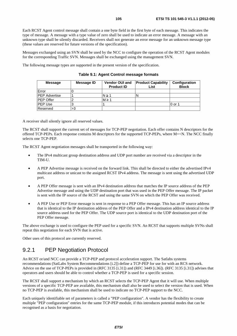
ETSI
ETSI TS 101 545-3 V1.1.1 (2012-05)105
Each RCST Agent control message shall contain a one byte field in the first byte of each message. This indicates the type of message. A message with a type value of zero shall be used to indicate an error message. A message with an unknown type shall be silently discarded. Receivers shall not generate an error message for an unknown message type (these values are reserved for future versions of the specification).
Messages exchanged using an SVN shall be used by the NCC to configure the operation of the RCST Agent modules for the corresponding Traffic SVN. Messages shall be exchanged using the management SVN.
The following message types are supported in the present version of the specification.
Table 9.1: Agent Control message formats
Message Message ID Vendor OUI and Product ID
Product Capability List
Configuration Block
Error 0 PEP Advertise 1 N ≥ 1 N PEP Offer 2 M ≥ 1 PEP Use 3 1 0 or 1 Reserved >3
A receiver shall silently ignore all reserved values.
The RCST shall support the current set of messages for TCP-PEP negotiation. Each offer contains N descriptors for the offered TCP-PEPs. Each response contains M descriptors for the supported TCP-PEPs, where M=<N. The NCC finally selects one TCP-PEP.
The RCST Agent negotiation messages shall be transported in the following way:
• The IPv4 multicast group destination address and UDP port number are received via a descriptor in the TIM-U.
• A PEP Advertise message is received on the forward link. This shall be directed to either the advertised IPv4 multicast address or unicast to the assigned RCST IPv4 address. The message is sent using the advertised UDP port.
• A PEP Offer message is sent with an IPv4 destination address that matches the IP source address of the PEP Advertise message and using the UDP destination port that was used in the PEP Offer message. The IP packet is sent with the IP source of the RCST and using the same SVN on which the PEP Offer was received.
• A PEP Use or PEP Error message is sent in response to a PEP Offer message. This has an IP source address that is identical to the IP destination address of the PEP Offer and a IPv4 destination address identical to the IP source address used for the PEP Offer. The UDP source port is identical to the UDP destination port of the PEP Offer message.
The above exchange is used to configure the PEP used for a specific SVN. An RCST that supports multiple SVNs shall repeat this negotiation for each SVN that is active.
Other uses of this protocol are currently reserved.
9.2.1 PEP Negotiation Protocol
An RCST or/and NCC can provide a TCP-PEP and protocol acceleration support. The Satlabs systems recommendations (SatLabs System Recommendations [i.2]) define a TCP-PEP for use for with an RCS network. Advice on the use of TCP-PEPs is provided in (RFC 3135 [i.31]) and (RFC 3449 [i.36]). (RFC 3135 [i.31]) advises that operators and users should be able to control whether a TCP-PEP is used for a specific session.
The RCST shall support a mechanism by which an RCST selects the TCP-PEP Agent that it will use. When multiple versions of a specific TCP-PEP are available, this mechanism shall also be used to select the version that is used. When no TCP-PEP is available, this mechanism shall be used to indicate no TCP-PEP support to the NCC.
Each uniquely identifiable set of parameters is called a "PEP configuration". A vendor has the flexibility to create multiple "PEP configuration" entries for the same TCP-PEP module, if this introduces potential modes that can be recognised as a basis for negotiation.
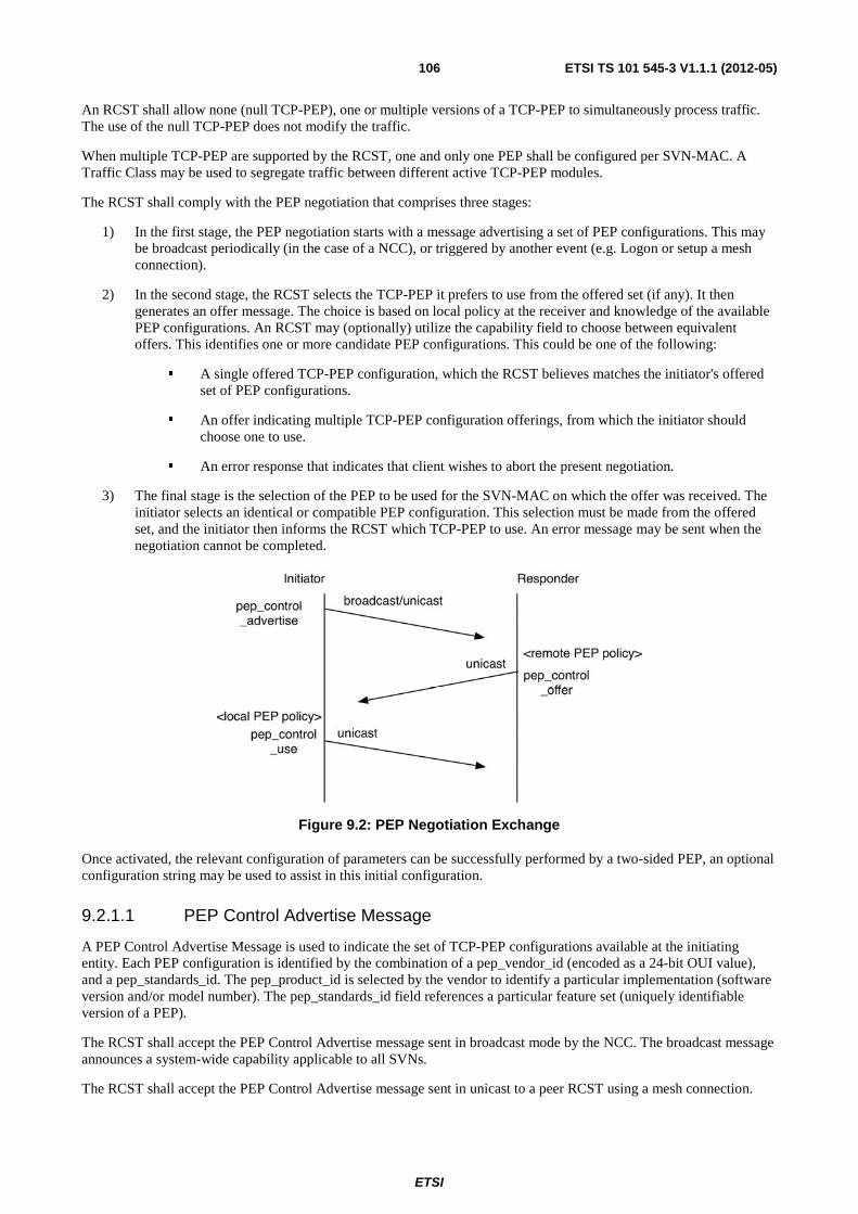
ETSI
ETSI TS 101 545-3 V1.1.1 (2012-05)106
An RCST shall allow none (null TCP-PEP), one or multiple versions of a TCP-PEP to simultaneously process traffic. The use of the null TCP-PEP does not modify the traffic.
When multiple TCP-PEP are supported by the RCST, one and only one PEP shall be configured per SVN-MAC. A Traffic Class may be used to segregate traffic between different active TCP-PEP modules.
The RCST shall comply with the PEP negotiation that comprises three stages:
1) In the first stage, the PEP negotiation starts with a message advertising a set of PEP configurations. This may be broadcast periodically (in the case of a NCC), or triggered by another event (e.g. Logon or setup a mesh connection).
2) In the second stage, the RCST selects the TCP-PEP it prefers to use from the offered set (if any). It then generates an offer message. The choice is based on local policy at the receiver and knowledge of the available PEP configurations. An RCST may (optionally) utilize the capability field to choose between equivalent offers. This identifies one or more candidate PEP configurations. This could be one of the following:
� A single offered TCP-PEP configuration, which the RCST believes matches the initiator's offered set of PEP configurations.
� An offer indicating multiple TCP-PEP configuration offerings, from which the initiator should choose one to use.
� An error response that indicates that client wishes to abort the present negotiation.
3) The final stage is the selection of the PEP to be used for the SVN-MAC on which the offer was received. The initiator selects an identical or compatible PEP configuration. This selection must be made from the offered set, and the initiator then informs the RCST which TCP-PEP to use. An error message may be sent when the negotiation cannot be completed.
Figure 9.2: PEP Negotiation Exchange
Once activated, the relevant configuration of parameters can be successfully performed by a two-sided PEP, an optional configuration string may be used to assist in this initial configuration.
9.2.1.1 PEP Control Advertise Message
A PEP Control Advertise Message is used to indicate the set of TCP-PEP configurations available at the initiating entity. Each PEP configuration is identified by the combination of a pep_vendor_id (encoded as a 24-bit OUI value), and a pep_standards_id. The pep_product_id is selected by the vendor to identify a particular implementation (software version and/or model number). The pep_standards_id field references a particular feature set (uniquely identifiable version of a PEP).
The RCST shall accept the PEP Control Advertise message sent in broadcast mode by the NCC. The broadcast message announces a system-wide capability applicable to all SVNs.
The RCST shall accept the PEP Control Advertise message sent in unicast to a peer RCST using a mesh connection.
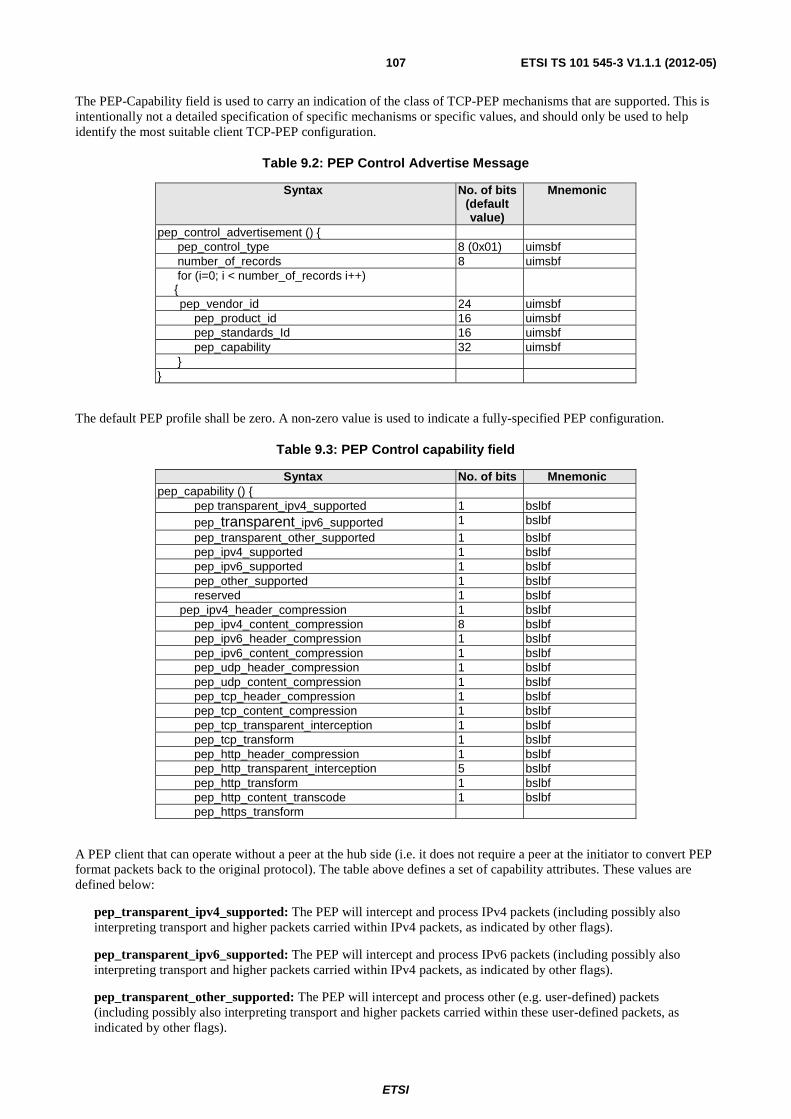
ETSI
ETSI TS 101 545-3 V1.1.1 (2012-05)107
The PEP-Capability field is used to carry an indication of the class of TCP-PEP mechanisms that are supported. This is intentionally not a detailed specification of specific mechanisms or specific values, and should only be used to help identify the most suitable client TCP-PEP configuration.
Table 9.2: PEP Control Advertise Message
Syntax No. of bits (default value)
Mnemonic
pep_control_advertisement () { pep_control_type 8 (0x01) uimsbf number_of_records 8 uimsbf for (i=0; i < number_of_records i++) {
pep_vendor_id 24 uimsbf pep_product_id 16 uimsbf pep_standards_Id 16 uimsbf pep_capability 32 uimsbf } }
The default PEP profile shall be zero. A non-zero value is used to indicate a fully-specified PEP configuration.
Table 9.3: PEP Control capability field
Syntax No. of bits Mnemonic pep_capability () { pep transparent_ipv4_supported 1 bslbf pep_transparent_ipv6_supported 1 bslbf
pep_transparent_other_supported 1 bslbf pep_ipv4_supported 1 bslbf pep_ipv6_supported 1 bslbf pep_other_supported 1 bslbf reserved 1 bslbf pep_ipv4_header_compression 1 bslbf pep_ipv4_content_compression 8 bslbf pep_ipv6_header_compression 1 bslbf pep_ipv6_content_compression 1 bslbf pep_udp_header_compression 1 bslbf pep_udp_content_compression 1 bslbf pep_tcp_header_compression 1 bslbf pep_tcp_content_compression 1 bslbf pep_tcp_transparent_interception 1 bslbf pep_tcp_transform 1 bslbf pep_http_header_compression 1 bslbf pep_http_transparent_interception 5 bslbf pep_http_transform 1 bslbf pep_http_content_transcode 1 bslbf pep_https_transform
A PEP client that can operate without a peer at the hub side (i.e. it does not require a peer at the initiator to convert PEP format packets back to the original protocol). The table above defines a set of capability attributes. These values are defined below:
pep_transparent_ipv4_supported: The PEP will intercept and process IPv4 packets (including possibly also interpreting transport and higher packets carried within IPv4 packets, as indicated by other flags).
pep_transparent_ipv6_supported: The PEP will intercept and process IPv6 packets (including possibly also interpreting transport and higher packets carried within IPv4 packets, as indicated by other flags).
pep_transparent_other_supported: The PEP will intercept and process other (e.g. user-defined) packets (including possibly also interpreting transport and higher packets carried within these user-defined packets, as indicated by other flags).
ETSI
ETSI TS 101 545-3 V1.1.1 (2012-05)108
pep_ipv4_content_compression: The PEP will perform lossless compression of IPv4 content.
pep_ipv6_content_compression: The PEP will perform lossless compression of IPv6 content.
pep_udp_content_compression: The PEP will perform lossless compression of UDP content.
pep_tcp_content_compression: The PEP will perform lossless compression of TCP content.
pep_other_compression: The PEP will perform lossless compression of custom content.
pep_tcp_transparent_interception: The PEP will intercept TCP connections (e.g. split TCP) by preserving TCP compatibility.
pep_http_transparent_interception: The PEP will intercept HTTP by preserving HTTP compatibility (e.g. pre-fetching).
pep_rtp_transparent_interception: The PEP will intercept RTP by preserving RTP compatibility.
pep_http_transcode: The PEP will perform HTTP content transcoding (e.g. image/voice codec transcoding).
pep_rtp_transcode: The PEP will perform RTP content transcoding.
pep_other_transcode: The PEP will perform transcoding of custom content.
One-sided operation use only a PEP at the advertising end, and no enhancement at the remote end. Remote sides may therefore reasonably expect that one-sided enhancements will be able to provide some form of acceleration.
The following capability attributes resemble those defined for one-way operation, but require a corresponding PEP entity at the remote end. The specifics of the PEP method depend on the specific implementation as defined by the combination of (pep_vendor_id, pep_product_id, pep_standards) fields.
pep_ipv4_supported: The PEP will intercept and process IPv4 packets (including possibly also interpreting transport and higher packets carried within IPv4 packets, as indicated by other flags). If this field is ‘0’, the PEP will not perform any of the functions listed below for IPv4 traffic.
pep_ipv6_supported: The PEP will intercept and process IPv6 packets (including possibly also interpreting transport and higher packets carried within IPv6 packets, as indicated by other flags). If this field is ‘0’, the PEP will not perform any of the functions listed below for IPv6 traffic.
pep_other_supported: The PEP will intercept and process other (e.g. user-defined) packets (including possibly also interpreting transport and higher packets carried within these user-defined packets, as indicated by other flags). If this field is ‘0’, the PEP will not perform any of the functions listed below for these user-defined packets.
pep_ipv4_header_compression: The PEP will perform IPv4 header compression.
pep_ipv6_header_compression: The PEP will perform IPv6 header compression.
pep_udp_header_compression: The PEP will perform compression of UDP/IP headers.
pep_tcp_header_compression: The PEP will perform compression of TCP/IP headers.
pep_http_header_compression: The PEP will perform compression of HTTP headers.
pep_rtp_header_compression: The PEP will perform compression of RTP/UDP/IP headers.
pep_tcp_transform: The PEP will intercept TCP/IP connections (e.g. split TCP) through provisioning the remote peer to do the appropriate inverse transform.
pep_http_transform: The PEP will intercept HTTP/TCP/IP through provisioning the remote peer to do the appropriate inverse transform, according to the default method for the implementation.
pep_https_transform: The PEP will intercept HTTPS/TCP/IP through provisioning the remote peer to do the appropriate inverse transform.
pep_rtp_transform: The PEP will intercept RTP through provisioning the remote peer to do the appropriate inverse transform.
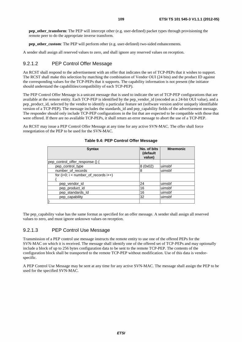
ETSI
ETSI TS 101 545-3 V1.1.1 (2012-05)109
pep_other_transform: The PEP will intercept other (e.g. user-defined) packet types through provisioning the remote peer to do the appropriate inverse transform.
pep_other_custom: The PEP will perform other (e.g. user-defined) two-sided enhancements.
A sender shall assign all reserved values to zero, and shall ignore any reserved values on reception.
9.2.1.2 PEP Control Offer Message
An RCST shall respond to the advertisement with an offer that indicates the set of TCP-PEPs that it wishes to support. The RCST shall make this selection by matching the combination of Vendor OUI (24 bits) and the product ID against the corresponding values for the TCP-PEPs that it supports. The capability information is not present (the initiator should understand the capabilities/compatibility of each TCP-PEP).
The PEP Control Offer Message is a unicast message that is used to indicate the set of TCP-PEP configurations that are available at the remote entity. Each TCP-PEP is identified by the pep_vendor_id (encoded as a 24-bit OUI value), and a pep_product_id, selected by the vendor to identify a particular feature set (software version and/or uniquely identifiable version of a TCP-PEP). The message includes the standards_id and pep_capability fields of the advertisement message. The responder should only include TCP-PEP configurations in the list that are expected to be compatible with those that were offered. If there are no available TCP-PEPs, it shall return an error message to abort the use of a TCP-PEP.
An RCST may issue a PEP Control Offer Message at any time for any active SVN-MAC. The offer shall force renegotiation of the PEP to be used for the SVN-MAC.
Table 9.4: PEP Control Offer Message
Syntax No. of bits (default value)
Mnemonic
pep_control_offer_response () { pep_control_type 8 (0x02) uimsbf number_of_records 8 uimsbf for (i=0; i < number_of_records i++) {
pep_vendor_id 24 uimsbf pep_product_id 16 uimsbf pep_standards_Id 16 uimsbf pep_capability 32 uimsbf }
The pep_capability value has the same format as specified for an offer message. A sender shall assign all reserved values to zero, and must ignore unknown values on reception.
9.2.1.3 PEP Control Use Message
Transmission of a PEP control use message instructs the remote entity to use one of the offered PEPs for the SVN-MAC on which it is received. The message shall identify one of the offered set of TCP-PEPs and may optionally include a block of up to 256 bytes configuration data to be sent to the remote TCP-PEP. The contents of the configuration block shall be transported to the remote TCP-PEP without modification. Use of this data is vendor-specific.
A PEP Control Use Message may be sent at any time for any active SVN-MAC. The message shall assign the PEP to be used for the specified SVN-MAC.
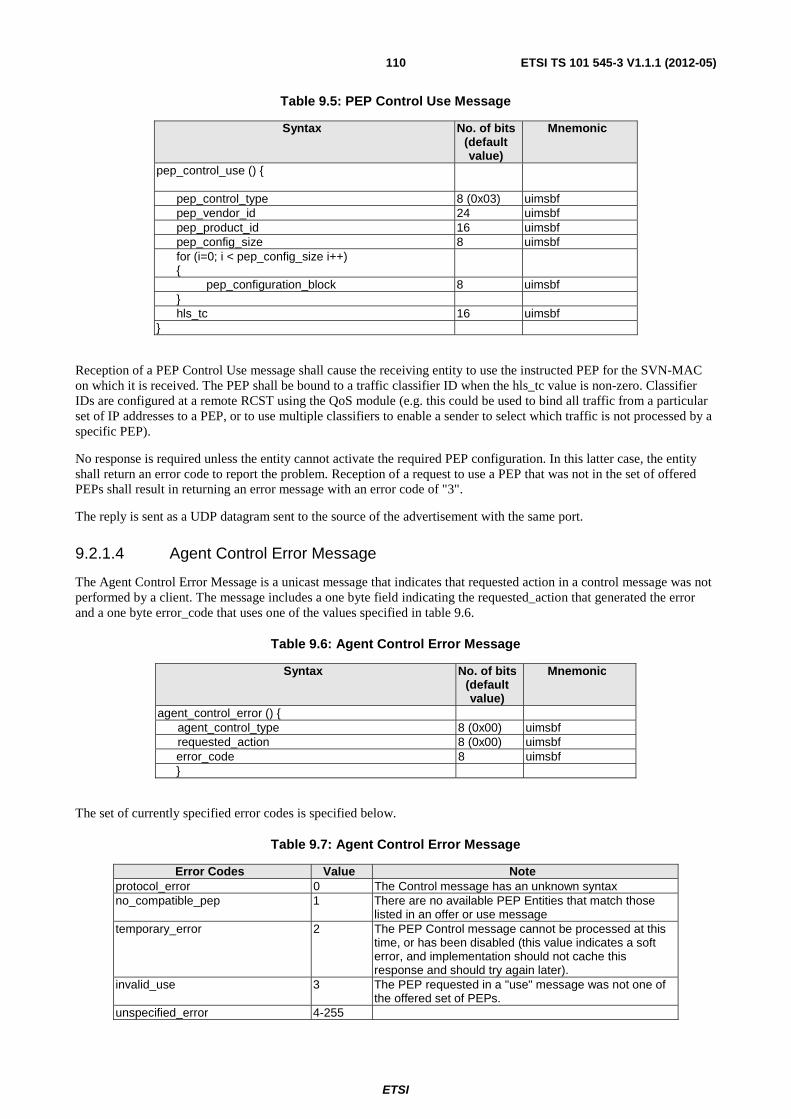
ETSI
ETSI TS 101 545-3 V1.1.1 (2012-05)110
Table 9.5: PEP Control Use Message
Syntax No. of bits (default value)
Mnemonic
pep_control_use () {
pep_control_type 8 (0x03) uimsbf pep_vendor_id 24 uimsbf pep_product_id 16 uimsbf pep_config_size 8 uimsbf for (i=0; i < pep_config_size i++) {
pep_configuration_block 8 uimsbf } hls_tc 16 uimsbf }
Reception of a PEP Control Use message shall cause the receiving entity to use the instructed PEP for the SVN-MAC on which it is received. The PEP shall be bound to a traffic classifier ID when the hls_tc value is non-zero. Classifier IDs are configured at a remote RCST using the QoS module (e.g. this could be used to bind all traffic from a particular set of IP addresses to a PEP, or to use multiple classifiers to enable a sender to select which traffic is not processed by a specific PEP).
No response is required unless the entity cannot activate the required PEP configuration. In this latter case, the entity shall return an error code to report the problem. Reception of a request to use a PEP that was not in the set of offered PEPs shall result in returning an error message with an error code of "3".
The reply is sent as a UDP datagram sent to the source of the advertisement with the same port.
9.2.1.4 Agent Control Error Message
The Agent Control Error Message is a unicast message that indicates that requested action in a control message was not performed by a client. The message includes a one byte field indicating the requested_action that generated the error and a one byte error_code that uses one of the values specified in table 9.6.
Table 9.6: Agent Control Error Message
Syntax No. of bits (default value)
Mnemonic
agent_control_error () { agent_control_type 8 (0x00) uimsbf requested_action 8 (0x00) uimsbf error_code 8 uimsbf }
The set of currently specified error codes is specified below.
Table 9.7: Agent Control Error Message
Error Codes Value Note protocol_error 0 The Control message has an unknown syntax no_compatible_pep 1 There are no available PEP Entities that match those
listed in an offer or use message temporary_error 2 The PEP Control message cannot be processed at this
time, or has been disabled (this value indicates a soft error, and implementation should not cache this response and should try again later).
invalid_use 3 The PEP requested in a "use" message was not one of the offered set of PEPs.
unspecified_error 4-255
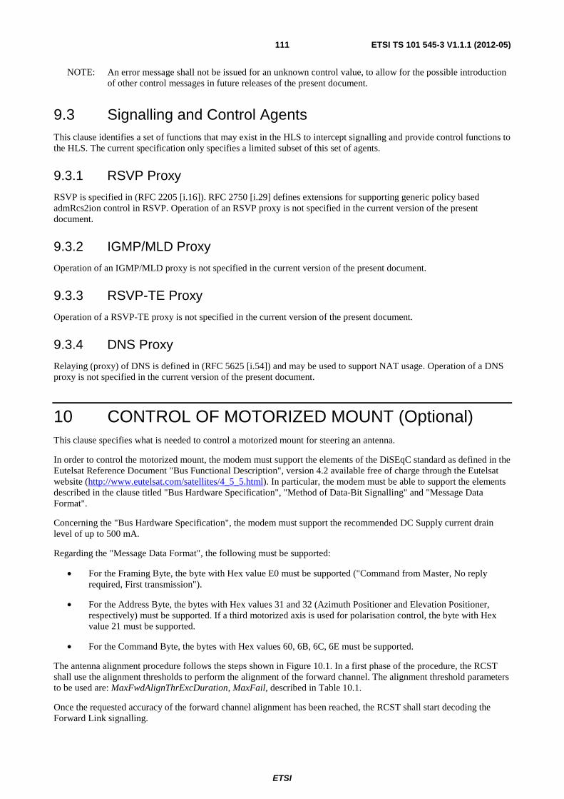
ETSI
ETSI TS 101 545-3 V1.1.1 (2012-05)111
NOTE: An error message shall not be issued for an unknown control value, to allow for the possible introduction of other control messages in future releases of the present document.
9.3 Signalling and Control Agents This clause identifies a set of functions that may exist in the HLS to intercept signalling and provide control functions to the HLS. The current specification only specifies a limited subset of this set of agents.
9.3.1 RSVP Proxy
RSVP is specified in (RFC 2205 [i.16]). RFC 2750 [i.29] defines extensions for supporting generic policy based admRcs2ion control in RSVP. Operation of an RSVP proxy is not specified in the current version of the present document.
9.3.2 IGMP/MLD Proxy
Operation of an IGMP/MLD proxy is not specified in the current version of the present document.
9.3.3 RSVP-TE Proxy
Operation of a RSVP-TE proxy is not specified in the current version of the present document.
9.3.4 DNS Proxy
Relaying (proxy) of DNS is defined in (RFC 5625 [i.54]) and may be used to support NAT usage. Operation of a DNS proxy is not specified in the current version of the present document.
10 CONTROL OF MOTORIZED MOUNT (Optional) This clause specifies what is needed to control a motorized mount for steering an antenna.
In order to control the motorized mount, the modem must support the elements of the DiSEqC standard as defined in the Eutelsat Reference Document "Bus Functional Description", version 4.2 available free of charge through the Eutelsat website (http://www.eutelsat.com/satellites/4_5_5.html). In particular, the modem must be able to support the elements described in the clause titled "Bus Hardware Specification", "Method of Data-Bit Signalling" and "Message Data Format".
Concerning the "Bus Hardware Specification", the modem must support the recommended DC Supply current drain level of up to 500 mA.
Regarding the "Message Data Format", the following must be supported:
• For the Framing Byte, the byte with Hex value E0 must be supported ("Command from Master, No reply required, First transmission").
• For the Address Byte, the bytes with Hex values 31 and 32 (Azimuth Positioner and Elevation Positioner, respectively) must be supported. If a third motorized axis is used for polarisation control, the byte with Hex value 21 must be supported.
• For the Command Byte, the bytes with Hex values 60, 6B, 6C, 6E must be supported.
The antenna alignment procedure follows the steps shown in Figure 10.1. In a first phase of the procedure, the RCST shall use the alignment thresholds to perform the alignment of the forward channel. The alignment threshold parameters to be used are: MaxFwdAlignThrExcDuration, MaxFail, described in Table 10.1.
Once the requested accuracy of the forward channel alignment has been reached, the RCST shall start decoding the Forward Link signalling.

ETSI
ETSI TS 101 545-3 V1.1.1 (2012-05)112
Figure 10.1: RCST antenna alignment and logon
Table 10.1: Alignment parameters in the initial configuration
Parameter Description
MaxFwdAlignThrExcDuration The duration of the time interval during which fwd alignment accuracy must be achieved.
MaxFail Maximum number of alignment failures. The corresponding counter is incremented every time the state machine re-visits the FwdAligment state.

ETSI
ETSI TS 101 545-3 V1.1.1 (2012-05)113
Annex A (informative): RCST MIB Clause intentionally left blank.
This informative annex will include the new RCST MIB following the MIB objects requirements in clause 8, in a revised version of the present document.
The RCST MIB recommended syntax is ASN.1.

ETSI
ETSI TS 101 545-3 V1.1.1 (2012-05)114
Annex B (informative): RCST Configuration file Clause intentionally left blank.
This informative annex will include the configuration file in XML format following the MIB definition, in a revised version of the present document.
ETSI
ETSI TS 101 545-3 V1.1.1 (2012-05)115
Annex C (informative): Specification of the Software Download Delivery Protocol (SDDP)
C.1 Introduction The present annex defines a unidirectional multicast protocol, from hub to terminals allowing to update the Software run by Terminals. This is denoted SDDP (Software and Data Download Protocol) and allows sending Software files in a data carousel fashion (the same file transmission being sent successively in loops) In particular:
• This annex defines how to locate the forward link stream containing SDDP in a network.
• This annex defines the signalling information used to locate SDDP.
• This annex defines the transmission of SDDP as a standardized IP multicast.
• SDDP is based on the OUI (Organization Unique Identifier) identifying a terminal manufacturer.
• This annex defines components that can be used to enhance the SDDP functionality in an upward-compatible way. This provides a standard mechanism for carrying additional information, e.g. update scheduling information, extensive selection and targeting information, action notification, filtering descriptors.
C.2 Scope DVB-RCS2 terminal software is complex. To guarantee the functionality of a terminal, as well as increasing its functionality once deployed in the field, a software update service is required. The present annex specifies a mechanism for signalling a software update service and the means to carry the data for this software update service.
The SDDP protocol takes advantage of the IP capabilities present in a DVB-RCS2 terminal to keep the lower layer implementation simple and unchanged from the DVB-RCS2 specification (DVB-RCS2). It also takes advantage of the multicast capabilities of DVB-S and DVB-S2.
C.3 Overview of the Basic Protocol A file transfer begins with a request send from the Hub to write a file (WRQ message) or an information (INFO message) indicating where the file is located. The transmission of the file content on the forward link then proceeds. The file is sent in fixed length blocks, specified by the block size parameter (see clause C.7), typically 512 bytes. Each data packet contains one block of data (DATA message). A data packet of less than the block size terminates the transfer.
Most errors cause termination of the transfer. Errors are caused by three types of events: not being able to satisfy the request (e.g. access violation), receiving a packet that cannot be explained by a delay in time or by duplication in the network (e.g. an incorrectly formed packet), and loss of access to a necessary resource (e.g. memory resources exhausted or access denied during a transfer).
SDDP recognizes only one error condition that does not cause termination, the source port of a received packet being incorrect.
This protocol is very restrictive, in order to simplify implementation. For example, the fixed length blocks makes allocation straightforward.
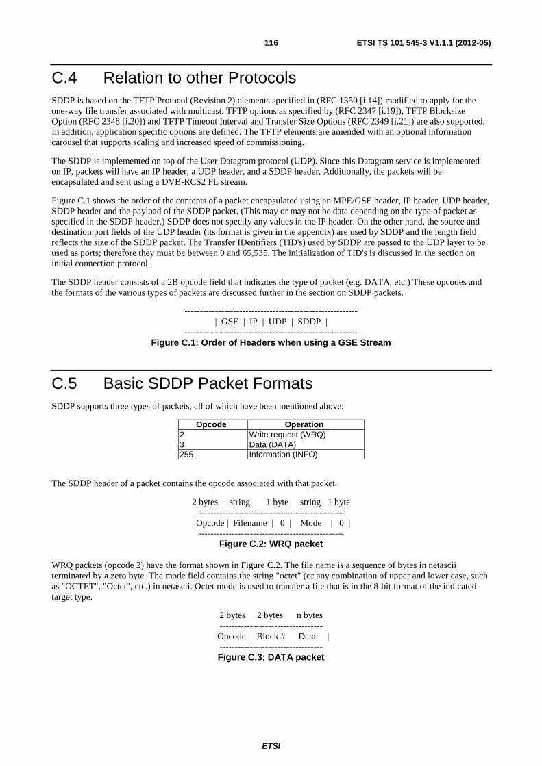
ETSI
ETSI TS 101 545-3 V1.1.1 (2012-05)116
C.4 Relation to other Protocols SDDP is based on the TFTP Protocol (Revision 2) elements specified in (RFC 1350 [i.14]) modified to apply for the one-way file transfer associated with multicast. TFTP options as specified by (RFC 2347 [i.19]), TFTP Blocksize Option (RFC 2348 [i.20]) and TFTP Timeout Interval and Transfer Size Options (RFC 2349 [i.21]) are also supported. In addition, application specific options are defined. The TFTP elements are amended with an optional information carousel that supports scaling and increased speed of commissioning.
The SDDP is implemented on top of the User Datagram protocol (UDP). Since this Datagram service is implemented on IP, packets will have an IP header, a UDP header, and a SDDP header. Additionally, the packets will be encapsulated and sent using a DVB-RCS2 FL stream.
Figure C.1 shows the order of the contents of a packet encapsulated using an MPE/GSE header, IP header, UDP header, SDDP header and the payload of the SDDP packet. (This may or may not be data depending on the type of packet as specified in the SDDP header.) SDDP does not specify any values in the IP header. On the other hand, the source and destination port fields of the UDP header (its format is given in the appendix) are used by SDDP and the length field reflects the size of the SDDP packet. The Transfer IDentifiers (TID's) used by SDDP are passed to the UDP layer to be used as ports; therefore they must be between 0 and 65,535. The initialization of TID's is discussed in the section on initial connection protocol.
The SDDP header consists of a 2B opcode field that indicates the type of packet (e.g. DATA, etc.) These opcodes and the formats of the various types of packets are discussed further in the section on SDDP packets.
--------------------------------------------------------- | GSE | IP | UDP | SDDP |
--------------------------------------------------------- Figure C.1: Order of Headers when using a GSE Stream
C.5 Basic SDDP Packet Formats SDDP supports three types of packets, all of which have been mentioned above:
Opcode Operation 2 Write request (WRQ) 3 Data (DATA) 255 Information (INFO)
The SDDP header of a packet contains the opcode associated with that packet.
2 bytes string 1 byte string 1 byte ------------------------------------------------
| Opcode | Filename | 0 | Mode | 0 | ------------------------------------------------
Figure C.2: WRQ packet
WRQ packets (opcode 2) have the format shown in Figure C.2. The file name is a sequence of bytes in netascii terminated by a zero byte. The mode field contains the string "octet" (or any combination of upper and lower case, such as "OCTET", "Octet", etc.) in netascii. Octet mode is used to transfer a file that is in the 8-bit format of the indicated target type.
2 bytes 2 bytes n bytes ----------------------------------
| Opcode | Block # | Data | ---------------------------------- Figure C.3: DATA packet
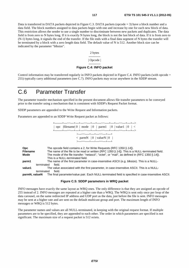
ETSI
ETSI TS 101 545-3 V1.1.1 (2012-05)117
Data is transferred in DATA packets depicted in Figure C.3. DATA packets (opcode = 3) have a block number and a data field. The block numbers assigned to data packets begin with one and increase by one for each new block of data. This restriction allows the sender to use a single number to discriminate between new packets and duplicates. The data field is from zero to N bytes long. If it is exactly N bytes long, the block is not the last block of data. If it is from zero to (N-1) bytes long, it signals the end of the transfer. If the file ends with a final data segment of N bytes the transfer will be terminated by a block with a zero length data field. The default value of N is 512. Another block size can be indicated by the parameter "blksize".
2 bytes ----------- | Opcode | -----------
Figure C.4: INFO packet
Control information may be transferred regularly in INFO packets depicted in Figure C.4. INFO packets (with opcode = 255) typically carry additional parameters (see C.7). INFO packets may occur anywhere in the SDDP stream.
C.6 Parameter Transfer The parameter transfer mechanism specified in the present document allows file transfer parameters to be conveyed prior to the transfer using a mechanism that is consistent with SDDP's Request Packet format.
SDDP parameters are appended to the Write Request and Information packets.
Parameters are appended to an SDDP Write Request packet as follows:
+-------+---~~---+---+---~~---+---+----~~----+---+---~~---+---+--> | opc |filename| 0 | mode | 0 | parm1 | 0 | value1 | 0 | < +-------+---~~---+---+---~~---+---+----~~----+---+---~~---+---+-->
>---~~----+---+---~~---+---+ < parmN | 0 | valueN | 0 | >---~~----+---+---~~---+---+
Opc The opcode field contains a 2, for Write Requests (RFC 1350 [i.14]). Filename The name of the file to be read or written (RFC 1350 [i.14]). This is a NULL-terminated field. Mode The mode of the file transfer: "netascii", "octet", or "mail", as defined in (RFC 1350 [i.14]). This is a NULL-terminated field. parm1 The name of the first parameter in case-insensitive ASCII (e.g. blksize). This is a NULL-
terminated field. value1 The value associated with the first parameter, in case-insensitive ASCII. This is a NULL-
terminated field. parmN, valueN The final parameter/value pair. Each NULL-terminated field is specified in case-insensitive ASCII.
Figure C.5: SDDP parameters in WRQ packet
INFO messages have exactly the same layout as WRQ ones. The only difference is that they are assigned an opcode of 255 instead of 2. INFO messages are repeated at a higher rate than a WRQ. The WRQ is sent only once per loop of the data carousel, on the same redirected IP address and UDP port as the data, just before the file is sent. INFO messages may be sent at a higher rate and are sent on the default multicast group and port. The maximum length of INFO messages or WRQ is 512 bytes.
The parameter names and values are all NULL-terminated, in keeping with the original request format. If multiple parameters are to be specified, they are appended to each other. The order in which parameters are specified is not significant. The maximum size of a request packet is 512 octets.
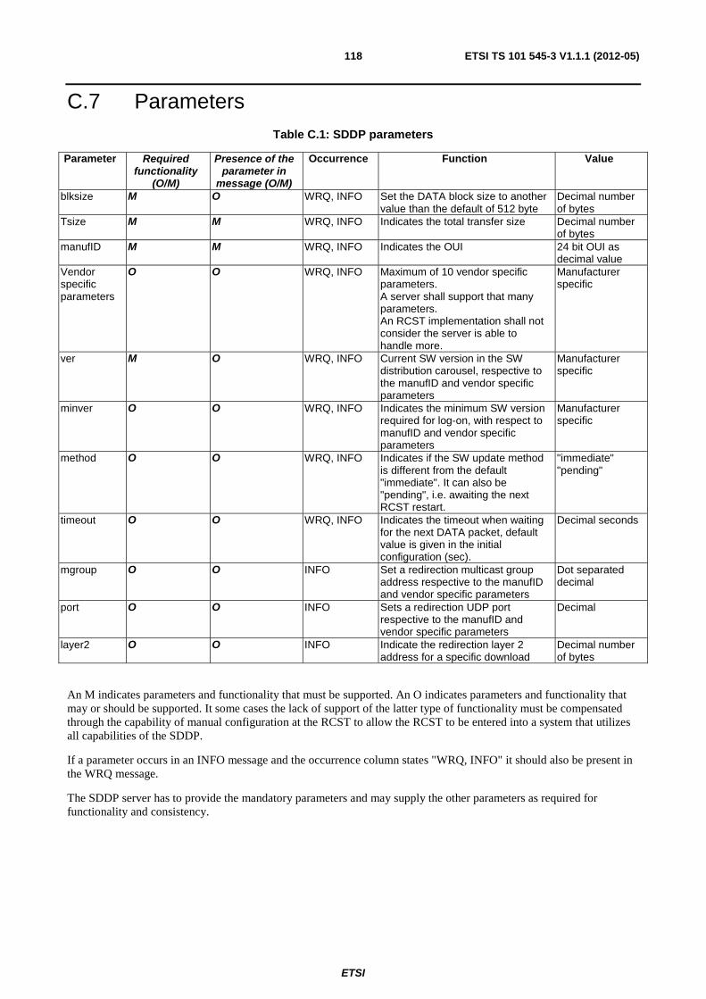
ETSI
ETSI TS 101 545-3 V1.1.1 (2012-05)118
C.7 Parameters Table C.1: SDDP parameters
Parameter Required functionality
(O/M)
Presence of the parameter in
message (O/M)
Occurrence Function Value
blksize M O WRQ, INFO Set the DATA block size to another value than the default of 512 byte
Decimal number of bytes
Tsize M M WRQ, INFO Indicates the total transfer size Decimal number of bytes
manufID M M WRQ, INFO Indicates the OUI 24 bit OUI as decimal value
Vendor specific parameters
O O WRQ, INFO Maximum of 10 vendor specific parameters. A server shall support that many parameters. An RCST implementation shall not consider the server is able to handle more.
Manufacturer specific
ver M O WRQ, INFO Current SW version in the SW distribution carousel, respective to the manufID and vendor specific parameters
Manufacturer specific
minver O O WRQ, INFO Indicates the minimum SW version required for log-on, with respect to manufID and vendor specific parameters
Manufacturer specific
method O O WRQ, INFO Indicates if the SW update method is different from the default "immediate". It can also be "pending", i.e. awaiting the next RCST restart.
"immediate" "pending"
timeout O O WRQ, INFO Indicates the timeout when waiting for the next DATA packet, default value is given in the initial configuration (sec).
Decimal seconds
mgroup O O INFO Set a redirection multicast group address respective to the manufID and vendor specific parameters
Dot separated decimal
port O O INFO Sets a redirection UDP port respective to the manufID and vendor specific parameters
Decimal
layer2 O O INFO Indicate the redirection layer 2 address for a specific download
Decimal number of bytes
An M indicates parameters and functionality that must be supported. An O indicates parameters and functionality that may or should be supported. It some cases the lack of support of the latter type of functionality must be compensated through the capability of manual configuration at the RCST to allow the RCST to be entered into a system that utilizes all capabilities of the SDDP.
If a parameter occurs in an INFO message and the occurrence column states "WRQ, INFO" it should also be present in the WRQ message.
The SDDP server has to provide the mandatory parameters and may supply the other parameters as required for functionality and consistency.
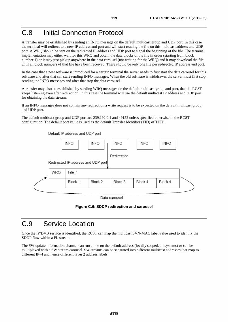
ETSI
ETSI TS 101 545-3 V1.1.1 (2012-05)119
C.8 Initial Connection Protocol A transfer may be established by sending an INFO message on the default multicast group and UDP port. In this case the terminal will redirect to a new IP address and port and will start reading the file on this multicast address and UDP port. A WRQ should be sent on the redirected IP address and UDP port to signal the beginning of the file. The terminal implementation may either wait for this WRQ and obtain the data blocks of the file in order (starting from block number 1) or it may just pickup anywhere in the data carousel (not waiting for the WRQ) and it may download the file until all block numbers of that file have been received. There should be only one file per redirected IP address and port.
In the case that a new software is introduced for a certain terminal the server needs to first start the data carousel for this software and after that can start sending INFO messages. When the old software is withdrawn, the server must first stop sending the INFO messages and after that stop the data carousel.
A transfer may also be established by sending WRQ messages on the default multicast group and port, that the RCST keeps listening even after redirection. In this case the terminal will use the default multicast IP address and UDP port for obtaining the data stream.
If an INFO messages does not contain any redirection a write request is to be expected on the default multicast group and UDP port.
The default multicast group and UDP port are 239.192.0.1 and 49152 unless specified otherwise in the RCST configuration. The default port value is used as the default Transfer Identifier (TID) of TFTP.
Figure C.6: SDDP redirection and carousel
C.9 Service Location Once the IP/DVB service is identified, the RCST can map the multicast SVN-MAC label value used to identify the SDDP flow within a FL stream.
The SW update information channel can run alone on the default address (locally scoped, all systems) or can be multiplexed with a SW stream/carousel. SW streams can be separated into different multicast addresses that map to different IPv4 and hence different layer 2 address labels.
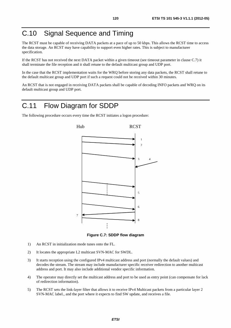
ETSI
ETSI TS 101 545-3 V1.1.1 (2012-05)120
C.10 Signal Sequence and Timing The RCST must be capable of receiving DATA packets at a pace of up to 50 kbps. This allows the RCST time to access the data storage. An RCST may have capability to support even higher rates. This is subject to manufacturer specification.
If the RCST has not received the next DATA packet within a given timeout (see timeout parameter in clause C.7) it shall terminate the file reception and it shall retune to the default multicast group and UDP port.
In the case that the RCST implementation waits for the WRQ before storing any data packets, the RCST shall retune to the default multicast group and UDP port if such a request could not be received within 30 minutes.
An RCST that is not engaged in receiving DATA packets shall be capable of decoding INFO packets and WRQ on its default multicast group and UDP port.
C.11 Flow Diagram for SDDP The following procedure occurs every time the RCST initiates a logon procedure:
RCST Hub
1
2
3 4
5
7
6
8
Figure C.7: SDDP flow diagram
1) An RCST in initialization mode tunes onto the FL.
2) It locates the appropriate L2 multicast SVN-MAC for SWDL.
3) It starts reception using the configured IPv4 multicast address and port (normally the default values) and decodes the stream. The stream may include manufacturer specific receiver redirection to another multicast address and port. It may also include additional vendor specific information.
4) The operator may directly set the multicast address and port to be used as entry point (can compensate for lack of redirection information).
5) The RCST sets the link-layer filter that allows it to receive IPv4 Multicast packets from a particular layer 2 SVN-MAC label., and the port where it expects to find SW update, and receives a file.
ETSI
ETSI TS 101 545-3 V1.1.1 (2012-05)121
As SW update download is completed, the RCST replaces the alternate SW load with the new downloaded SW and updates the dvbRcs2RCSTAlternateSoftwareVersion MIB parameter (RFC 5728 [i.55]).
6) In parallel the RCST will acquire the TBTP/TBTP2.
7) The RCST can send logon request in CSC slot.
8) The hub will respond with TIM-U.
Vendor specific configuration can prevent an RCST from logon until a given SW version has been downloaded. SW version can indeed be checked in the RCST capability field of the CSC burst (see DVB-RCS2). Otherwise the RCST logon will proceed in parallel with the SW download.
As an RCST continuously listens to the Forward Link Signalling, the SW download can be triggered at any time when multicast address and port are found.
C.12 Definition of multicast IP address The SW information channel should be located on the default multicast address. Vendor specific redirection information should be located in this channel. Alternatively the target multicast address and port can be configured manually at the RCST.
The default multicast address should be under control by the network operator and should not be used for user traffic. It is within the local network control block address range. Note that if IGMP is in use on the FL general IGMP queries can also occur addressed to this address. These will not interfere with SDDP that uses UDP.
The hub should block user traffic on the multicast addresses assigned to SW update to avoid any possibility of conflict. It is e.g. possible to select custom SW update multicast addresses from the Organization Local Scope multicast addresses. Another possibility is to use non-conflicting addresses from the Local Network Control Block, but note that packets with these addresses will not be forwarded by IP routers.
Administratively Scoped IP Multicast (RFC 2365 [i.22]) specifies:
239.192.0.0/14 is defined to be the IPv4 Organization Local Scope, and is the space from which an organization should allocate sub-ranges when defining scopes for private use.
C.13 Transfer Error Handling The RCST should discard duplicate packets and should also detect missing packets through the consecutive block numbering. The SW acceptance process of the RCST should include vendor specific consistency control of the received data.
C.14 Vendor-Specific Methods Additional vendor specific parameters may be included as required as in TFTP.
An RCST must ignore any unknown parameters.

ETSI
ETSI TS 101 545-3 V1.1.1 (2012-05)122
C.15 Location of the Assigned Layer 2 Address This clause specifies actions when operating in a transition mode, An RCST using a FL in the MPEG-TS mode will detect the PID on which it will listen for the SW update information stream in the following manner:
Before logon:
• directly on a layer with an address identified by MMT lookup
After logon:
• through a direct address mapping to a multicast SVN-MAC label
• through the Forward Interaction Path descriptor [3] received as logon response
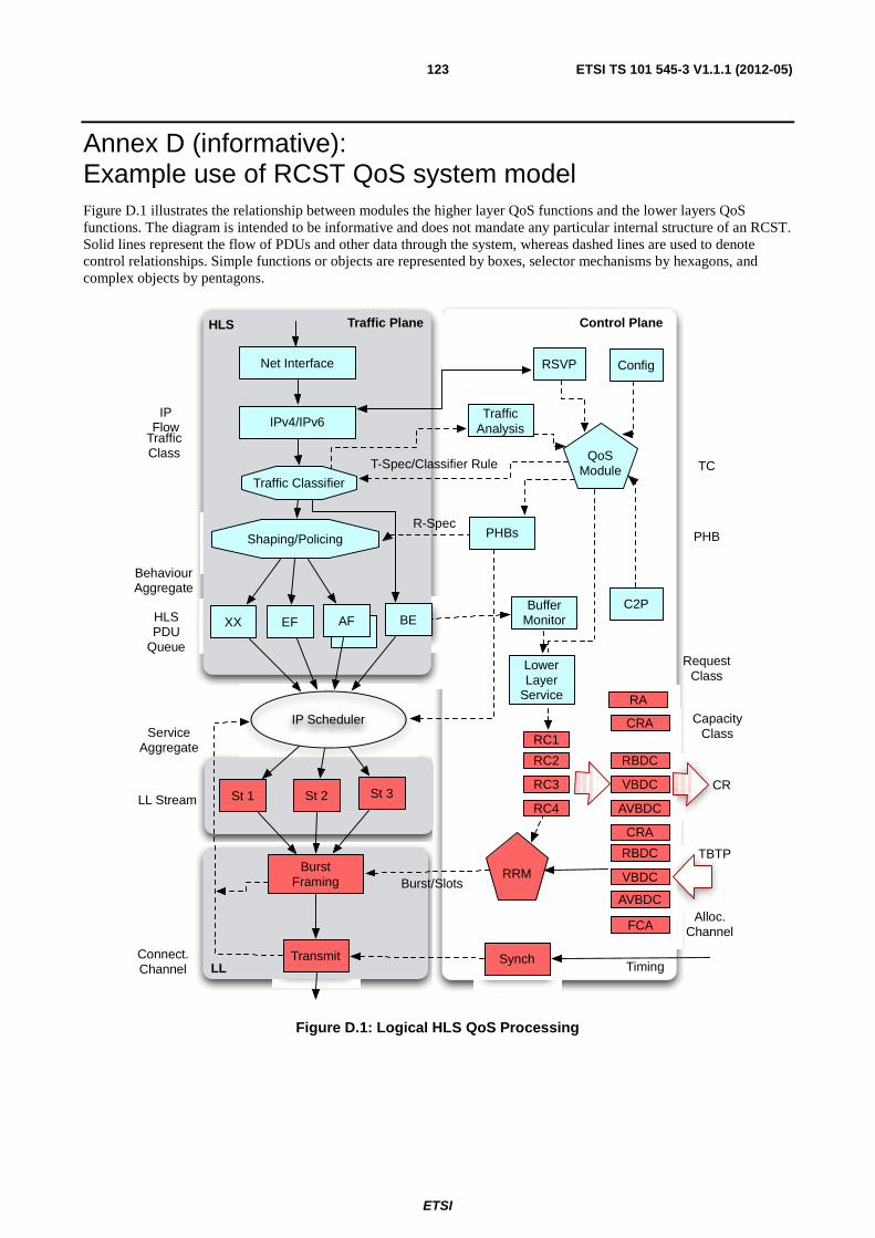
ETSI
ETSI TS 101 545-3 V1.1.1 (2012-05)123
Annex D (informative): Example use of RCST QoS system model Figure D.1 illustrates the relationship between modules the higher layer QoS functions and the lower layers QoS functions. The diagram is intended to be informative and does not mandate any particular internal structure of an RCST. Solid lines represent the flow of PDUs and other data through the system, whereas dashed lines are used to denote control relationships. Simple functions or objects are represented by boxes, selector mechanisms by hexagons, and complex objects by pentagons.
TrafficClass
AF
IPv4/IPv6
Traffic Classifier
Shaping/Policing
XX EF AF
IP Scheduler
Net Interface
LL
QoSModule
TrafficAnalysis
RSVP
BE
St 1 St 2 St 3
Burst Framing
RRM
Synch
TBTP
TransmitTiming
T-Spec/Classifier Rule
BufferMonitor
HLS
PHBsR-Spec
RC2
RC1
RC3
RC4
RBDC
CRA
VBDC
AVBDC
RBDC
CRA
VBDC
AVBDC
CR
FCA
LowerLayer
Service
Control PlaneTraffic Plane
IPFlow
HLSPDU
Queue
LL Stream
Connect.Channel
PHB
TC
RequestClass
CapacityClass
Alloc.Channel
RA
Burst/Slots
C2P
Config
ServiceAggregate
BehaviourAggregate
Figure D.1: Logical HLS QoS Processing

ETSI
ETSI TS 101 545-3 V1.1.1 (2012-05)124
In the diagram, the data paths are represented by dashed lines and control paths by dashed lines. Traffic arriving at the LAN network interface of an RCST has been divided into several Traffic Classes (TCs). These classes are mapped to 5 per-hop behaviours (PHBs). These traffic classes may for instance reflect a best effort Diffserv Code Point (TC1), and unknown service category (TC2) – in this case mapped to the Best Effort (BE) PHB, an Assured Forwarding codepoint mapped to one of the two AF PHBs, and an Expedited Forwarding class mapped to the EF PHB. The final traffic class maps to be a special-purpose class, the XX PHB. Each HLS PDU queue (behaviour aggregate) is in turn mapped to a Link Stream (service aggregate) for transmission (ST1-ST3). The Radio Resource Management (RRM) object is responsible for requesting capacity from the NCC.
The outputs of the HLS PDU Queues hold the data to be sent over the lower layer service. This implies the action of an IP scheduler (represented by a white oval). This may be understood to be activated each transmission opportunity (notified by the TBTP) to select the PDUs that are segmented into the stream. The selection is based on the PHBs (which indicate the lower service), and link-layer information. This ensures that PDUs or segmented PDUs are sent using the corresponding allocation channel. When required, PDUs pass through a segmentation function, so that any unsent data is postponed to a later scheduling opportunity. Each segment is then encapsulated into one of the configured streams (ST1-ST3 in the diagram) and is then placed in the burst for transmission. The scheduler could use a strict priority scheduler or a weighted priority scheduler, but is not specified in the present document. Since in this example there are three Link Streams, ST1 can preempt ST2 or ST3.
ETSI
ETSI TS 101 545-3 V1.1.1 (2012-05)125
Annex E (informative): The Connection Control Protocol (C2P) Dynamic connectivity may be supported thanks to the Connection Control Protocol (C2P). C2P is a control signalling protocol between the NCC and the RCST. C2P allows the mapping of IP parameters and policies to L2 parameters, and to dynamically set connectivity channels to an RCST according to set of values configured by management.
E.1 C2P Functions The current C2P [i.3] [i.4] is seen as a complement to the functionality of the interfaces already defined in the DVB-RCS2 and DVB-S/S2 standards. The functions added by the C2P protocol to the control plane of DVB-RCS2 can be summarized as:
• Establishment/modification/release of connectivity channels between sets of communicating parties (network elements) in a DVB-RCS2 system (RCSTs, Gateway, NCC).
• QoS-driven dynamic allocation of bandwidth resources connectivity channels, following the execution of a Connection Admission Control (CAC) function.
• Dynamic control of the communicating parties in the DVB-RCS2 system, via configuration parameters and policies.
• Dynamic allocation/assignment of logical resources to allocation channels.
• Address resolution for the purpose of RLE/GSE encapsulation.
• Definition of isolated and independent satellite sub-networks within the global interactive network (i.e. each subnetwork is characterized by its own terminal population, bandwidth resources, addressing space/plan).
C2P functions implementation may also perform address resolution functions and IP routing functions.
E.2 C2P Procedures The C2P protocol performs unicast/multicast address resolution routing function, specifically for meshed systems. If the next hop IP address of an outgoing packet is not found in the AR database, a C2P connection establishment request is triggered by the RCST to find the L2 address of the next hop. In case that the system does not support the dynamic routing function (e.g. OSPF), the C2P protocol can assist the RCST with IP routing information.
The NCC allows establishment of C2P connections only between RCSTs belonging to the same OVN and located in a common VRF domain, otherwise rejecting the connection requests.
The complete C2P specification is to be completed together with the full specification of the mesh scenario profile for RCS2.
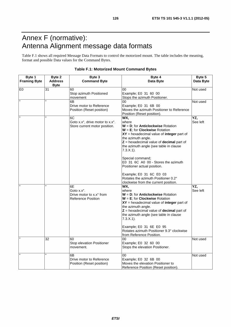
ETSI
ETSI TS 101 545-3 V1.1.1 (2012-05)126
Annex F (normative): Antenna Alignment message data formats Table F.1 shows all required Message Data Formats to control the motorized mount. The table includes the meaning, format and possible Data values for the Command Bytes.
Table F.1: Motorized Mount Command Bytes
Byte 1 Framing Byte
Byte 2 Address
Byte
Byte 3 Command Byte
Byte 4 Data Byte
Byte 5 Data Byte
E0 31
60 Stop azimuth Positioned movement
00 Example; E0 31 60 00 Stops the azimuth Positioner.
Not used
" " 6B Drive motor to Reference Position (Reset position)
00 Example; E0 31 6B 00 Moves the azimuth Positioner to Reference Position (Reset position).
Not used
" " 6C Goto x.x°, drive motor to x.x°. Store current motor position.
WX, where W = D; for Anticlockwise Rotation W = E; for Clockwise Rotation XY = hexadecimal value of integer part of the azimuth angle. Z = hexadecimal value of decimal part of the azimuth angle (see table in clause 7.3.X.1). Special command; E0 31 6C A0 00 - Stores the azimuth Positioner actual position. Example; E0 31 6C E0 03 Rotates the azimuth Positioner 0.2° clockwise from the current position.
YZ, See left
" " 6E Goto x.x°. Drive motor to x.x° from Reference Position
WX, where W = D; for Anticlockwise Rotation W = E; for Clockwise Rotation XY = hexadecimal value of integer part of the azimuth angle. Z = hexadecimal value of decimal part of the azimuth angle (see table in clause 7.3.X.1). Example; E0 31 6E E0 95 Rotates azimuth Positioner 9.3° clockwise from Reference Position.
YZ, See left
" 32
60 Stop elevation Positioner movement.
00 Example; E0 32 60 00 Stops the elevation Positioner.
Not used
" " 6B Drive motor to Reference Position (Reset position)
00 Example; E0 32 6B 00 Moves the elevation Positioner to Reference Position (Reset position).
Not used
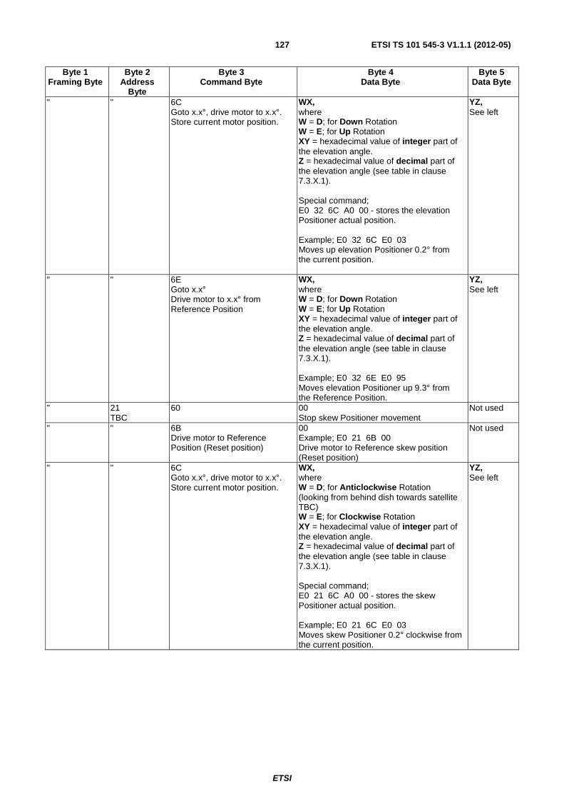
ETSI
ETSI TS 101 545-3 V1.1.1 (2012-05)127
Byte 1 Framing Byte
Byte 2 Address
Byte
Byte 3 Command Byte
Byte 4 Data Byte
Byte 5 Data Byte
" " 6C Goto x.x°, drive motor to x.x°. Store current motor position.
WX, where W = D; for Down Rotation W = E; for Up Rotation XY = hexadecimal value of integer part of the elevation angle. Z = hexadecimal value of decimal part of the elevation angle (see table in clause 7.3.X.1). Special command; E0 32 6C A0 00 - stores the elevation Positioner actual position. Example; E0 32 6C E0 03 Moves up elevation Positioner 0.2° from the current position.
YZ, See left
" " 6E Goto x.x° Drive motor to x.x° from Reference Position
WX, where W = D; for Down Rotation W = E; for Up Rotation XY = hexadecimal value of integer part of the elevation angle. Z = hexadecimal value of decimal part of the elevation angle (see table in clause 7.3.X.1). Example; E0 32 6E E0 95 Moves elevation Positioner up 9.3° from the Reference Position.
YZ, See left
" 21 TBC
60 00 Stop skew Positioner movement
Not used
" " 6B Drive motor to Reference Position (Reset position)
00 Example; E0 21 6B 00 Drive motor to Reference skew position (Reset position)
Not used
" " 6C Goto x.x°, drive motor to x.x°. Store current motor position.
WX, where W = D; for Anticlockwise Rotation (looking from behind dish towards satellite TBC) W = E; for Clockwise Rotation XY = hexadecimal value of integer part of the elevation angle. Z = hexadecimal value of decimal part of the elevation angle (see table in clause 7.3.X.1). Special command; E0 21 6C A0 00 - stores the skew Positioner actual position. Example; E0 21 6C E0 03 Moves skew Positioner 0.2° clockwise from the current position.
YZ, See left

ETSI
ETSI TS 101 545-3 V1.1.1 (2012-05)128
Byte 1 Framing Byte
Byte 2 Address
Byte
Byte 3 Command Byte
Byte 4 Data Byte
Byte 5 Data Byte
" " 6E Goto x.x° Drive Motor to x.x° from Reference Position
WX, where W = D; for Anticlockwise Rotation (looking from behind dish towards satellite TBC) W = E; for Clockwise Rotation XY = hexadecimal value of integer part of the azimuth angle. Z = hexadecimal value of decimal part of the azimuth angle (see table in clause 7.3.X.1). Example; E0 21 6E E0 95 Rotates skew Positioner 9.3° clockwise from Reference Position.
YZ, See left
F.1 Hexadecimal value for the decimal part Table F.2: Hexadecimal value
Decimal Hex Decimal Hex 0.0° 0 0.5° 8 0.1° 2 0.6° A 0.2° 3 0.7° B 0.3° 5 0.8° D 0.4° 6 0.9° E
The hexadecimal value for the decimal part of the azimuth, elevation or skew angle (=Z) is in accordance with the following table.
F.2 Stored position The command to store the position of the azimuth Positioner is E0316CA000, for elevation Positioner it is E0326CA000 and for skew Positioner it is E0216CA000 (TBC). At the moment of sending these commands the motorized mount stores internally the actual positions.
To move the Positioners into these stored positions the commands are E0316CD000 for azimuth Positioner, E0326CD000 for elevation Positioner and E0216CD000 for skew Positioner.
F.3 Reference position (reset position) The motorized mount Reference Positions (Reset Positions) are fixed, factory set positions for the elevation, azimuth and skew Positioners.
The Azimuth Reference Position is the midpoint of the movement range of the azimuth axis. For a terminal pointed correctly it would correspond to pointing directly South/North (depending on installation being on Northern/Southern hemisphere).
The Elevation Reference Position is defined as the tangent line on the Earth surface of the place of installation. For a motorised mount perfectly on a vertical pole it would correspond to pointing directly towards the horizon.
The Skew Reference Position is the position when the skew is aligned with the vertical polarisation being exactly normal to the horizon (TBC).

ETSI
ETSI TS 101 545-3 V1.1.1 (2012-05)129
Annex G (informative): Bibliography ETSI EN 300 468: "Digital Video Broadcasting (DVB); Specification for Service Information (SI) in DVB Systems".
ETSI EN 301 192: "Digital Video Broadcasting (DVB); DVB specification for data broadcasting".
ETSI TS 102 294: "Satellite Earth Stations and Systems (SES); Broadband Satellite Multimedia (BSM) services and architectures; IP interworking via satellite; Multicast functional architecture".
ETSI TR 101 984: "Satellite Earth Stations and Systems (SES); Broadband Satellite Multimedia (BSM); Services and architectures".
ETSI TS 102 357: "Satellite Earth Stations and Systems (SES); Broadband Satellite Multimedia (BSM); Common Air interface specification; Satellite Independent Service Access Point SI-SAP".
IETF RFC 1633: "Integrated Services in the Internet Architecture: an Overview", Braden, R., Clark, D., and S. Shenker, June 1994.
IETF RFC 2210: "The Use of RSVP with IETF Integrated Services",Wroclawski, J., September 1997.
IETF RFC 2211: "Specification of the Controlled-Load Network Element Service",Wroclawski, J., September 1997.
IETF RFC 2212: "Specification of Guaranteed Quality of Service", Shenker, S., Partridge, C., and R. Guerin, September 1997.
IETF RFC 2578: "Structure of Management Information, Version 2 (SMIv2)", McCloghrie, K., Ed., Perkins, D., Ed., and J. Schoenwaelder, Ed., STD 58, April 1999.
IETF RFC 2597: "Assured Forwarding PHB Group", Heinanen, J., Baker, F., WeRcs2, W., and J. Wroclawski, June 1999.
IETF RFC 2697: "A Single Rate Three Color Marker", Heinanen, J. and R. Guerin, September 1999.
IETF RFC 2858: "Multiprotocol Extensions for BGP-4", Bates, T., Rekhter, Y., Chandra, R., and D. Katz, June 2000.
IETF RFC 2996: "Format of the RSVP DCLASS Object", Bernet, Y., November 2000.
IETF RFC 3164: "The BSD Syslog Protocol", Lonvick, C., August 2001.
IETF RFC 3181: "Signaled Preemption Priority Policy Element", Herzog, S., October 2001.
IETF RFC 3246: "An Expedited Forwarding PHB (Per-Hop Behavior)", Davie, B., Charny, A., Bennet, J.C., Benson, K., Le Boudec, J., Courtney, W., Davari, S., Firoiu, V., and D. Stiliadis, March 2002.
IETF RFC 3247: "Supplemental Information for the New Definition of the EF PHB (Expedited Forwarding Per-Hop Behavior)", Charny, A., Bennet, J., Benson, K., Boudec, J., Chiu, A., Courtney, W., Davari, S., Firoiu, V., Kalmanek, C., and K. Ramakrishnan, March 2002.
IETF RFC 3261: "SIP: Session Initiation Protocol", Rosenberg, J., Schulzrinne, H., Camarillo, G., Johnston, A., Peterson, J., Sparks, R., Handley, M., and E.,Schooler, June 2002.
IETF RFC 3290: "An Informal Management Model for Diffserv Routers", Bernet, Y., Blake, S., Grossman, D., and A. Smith, May 2002.
IETF RFC 3312: "Integration of Resource Management and Session Initiation Protocol (SIP)",Camarillo, G., Marshall, W., and J. Rosenberg, October 2002.
IETF RFC 4259: "A Framework for transmission of IP Datagrams over MPEG-2 Networks", Montpetit, M.-J., Fairhurst, G., Clausen, H., Collini-Nocker, B., and H. Linder, November 2005.
IETF RFC 4760: "Multiprotocol Extensions for BGP-4", Bates, T., Chandra, R., Katz, D., and Y. Rekhter, January 2007.

ETSI
ETSI TS 101 545-3 V1.1.1 (2012-05)130
"Internet Assigned Numbers Authority", Internet Assigned Numbers Authority, June 2008.
NOTE: available at http://www.iana.org.

ETSI
ETSI TS 101 545-3 V1.1.1 (2012-05)131
History
Document history
V1.1.1 May 2012 Publication