TRUNNION BALL VALVEWarning: Metallic materials selected using ANSI/NACE MR0175/ ISO 15156 are...
24
CAST TRUNNION BALL VALVE ATLAS SERIES
Transcript of TRUNNION BALL VALVEWarning: Metallic materials selected using ANSI/NACE MR0175/ ISO 15156 are...

CAST TRUNNIONBALL VALVE
ATLAS SERIES

2
BEHIND THE NAMEWith a renewed focus on product leadership through
innovation and quality, C&C is your world class provider
of flow solutions.
Atlas, a Titan known for his orientation and durability,
was tasked with shouldering the weight of the heavens.
Like enduring Atlas, the Atlas Series can take whatever
you throw at it. No matter the application or medium,
the Atlas will perform.

3
FLOW CONTROL SOLUTIONS FOR THE PETROLEUM & NATURAL GAS INDUSTRIES
Industry Specific SolutionsProduction, transportation, storage and processing
of oil and gas require the highest quality piping
components. This is our world.
In conjunction with our sister companies we supply
customers with valves, hammer unions, couplings,
connectors, actuators and other valve accessories
for high pressure process and piping at oil and gas
facilities, both above ground and offshore.
World Class & Worldwide Service We are dedicated to providing our customers with the
best — the best brands, the best service and the best
quality. Whether you require an automated valve for
a highly engineered project or a replacement valve
delivered same day, we are here to help. Our industry
experience, product selection and access to a global
network of partners enable us to tailor a solution to
solve your most difficult problem.
Expanding Our Product PortfolioWhile others are collapsing their portfolios and
cutting costs, we have an aggressive strategy to
supply complimentary products to served markets
and increase service levels to establish ourselves as
your single source provider for valve and flow control
solutions.
STANDARDS• Design/Materials: API 6D 24th Edition,
ASME B16.34
• Fire Safe: API 6FA/API 607 7th Edition
• End to End: ASME B16.10
• Flanged End: ASME B16.5
• Mounting: ISO 5211
• Testing: API 598/API 6D, CSA Z245.15-17
• API 6D Monogrammed
• PED 2014/68/EU Annex III, Module H
SPECIFICATIONS• Sizes 2” – 16”
• ANSI Class 150 – 1500
• Full Material Traceability
• ISO 5211 Actuator Adaptation
• Large Material Selection
• Low Operating Torques
• Anti-Static Blowout Proof Stem
• 100% Factory Testing
• Conforms to NACE MR0175/ISO 15156-1
APPLICATIONS• Transmission Pipelines
• Metering Skids
• Gas Gathering
• Terminals & Storage
• Natural Gas Plants
• Compression Stations

4
BLOWOUT PROOF STEM Positive stem retention is achieved within the
valve body.
ANTI-STATIC DESIGN Positive anti-static grounding between the ball,
stem and trunnion is a standard feature on the
Atlas Series.
BODY SEALINGThe double sealing design of the O-Rings and fire
safe graphite gaskets ensure zero leakage at the
body and closure connections.
EMERGENCY SEALANT INJECTIONValves are equipped with sealant injection
fittings at the stem and seat area. The seat
injection fittings have an integral buried check
valve to provide backup sealing. Should leakage
occur at either the seat or gland packing area,
leakage can temporarily be stopped by injecting
sealant into the secondary sealing system.
6
5
4
3
2
1 FIRE SAFE CERTIFIEDFire safe construction is standard on all trunnion
mounted ball valves. In the event of a fire,
secondary graphite seals and gaskets prevent
leakage to atmosphere and seat ring to ball
contact minimizes through leakage.
SINGLE PISTON EFFECT SEATSIn very low line pressure applications, sealing
between the seats and ball is achieved by seat
springs forcing the seat into the ball, resulting in
a seal. In high line pressure applications, the line
pressure, in conjunction with the spring load,
forces the upstream seat ring against the ball
resulting in tighter sealing.
The self-relieving seat, a standard design feature,
prevents excessive pressure buildup within the
valve by automatically relieving when body
cavity pressure exceeds the spring and line seat
pressure.
DESIGN HIGHLIGHTS
STANDARD
Self-Relieving Seats
5
56
4
4
4
32
1
Excess Body
Pressure

5
HOW TO ORDEREXAMPLE: A 6”, Class 600, 2 Piece Full Port Trunnion Ball Valve with Raised Face End Connections, Carbon Steel Body and 3mil Ball and
Stem with Single Piston Effect Devlon® Seats, HNBR 90 Durometer Seals and Lockable Worm Gear Operated is written as
606T2FRC3DHG.
A B C D E F G H I J
6 06 T2 F R C 3 D H G
E End Connection
R RF Flange
J RTJ Flange
W Buttweld - Sch 40
X Buttweld - Sch 80
Y Buttweld - Sch 160
B Pressure Class
01 Class 150
03 Class 300
06 Class 600
09 Class 900
15 Class 1500
C Valve Type
T2 2 Piece Trunnion Ball Valve
D Port
F Full
R Reduced
ASize
Inches DN
2 2" 50
3 3" 80
4 4" 100
6 6" 150
8 8" 200
10 10" 250
12 12" 300
14 14" 350
16 16" 400
F Body Material
C Carbon Steel ASTM A216 WCB
L Low Temperature Carbon Steel ASTM A352 LCC
S Stainless Steel ASTM A351 CF8M
G Trim Material
3 Carbon Steel See Trim Table (pg 19)
4 Low Temperature Carbon Steel See Trim Table (pg 19)
5 Stainless Steel See Trim Table (pg 19)
H Seat Material
D Devlon®
P PEEK
T TFM 1600
I Seal Material
H HNBR 90
V Viton® GLT 90
J Operator
B Bare Shaft
L Lockable Wrench
G Lockable Worm Gear
Warning: Metallic materials selected using ANSI/NACE MR0175/
ISO 15156 are resistant to cracking in defined H2S containing
environments in oil and gas production but not necessarily
immune to cracking under all service conditions. It is the
equipment user’s responsibility to select materials suitable for the
intended service.
Devlon® is a registered trademark of Devol Engineering, Ltd.
Viton® is a registered trademark of DuPont Dow Elastomers.
6
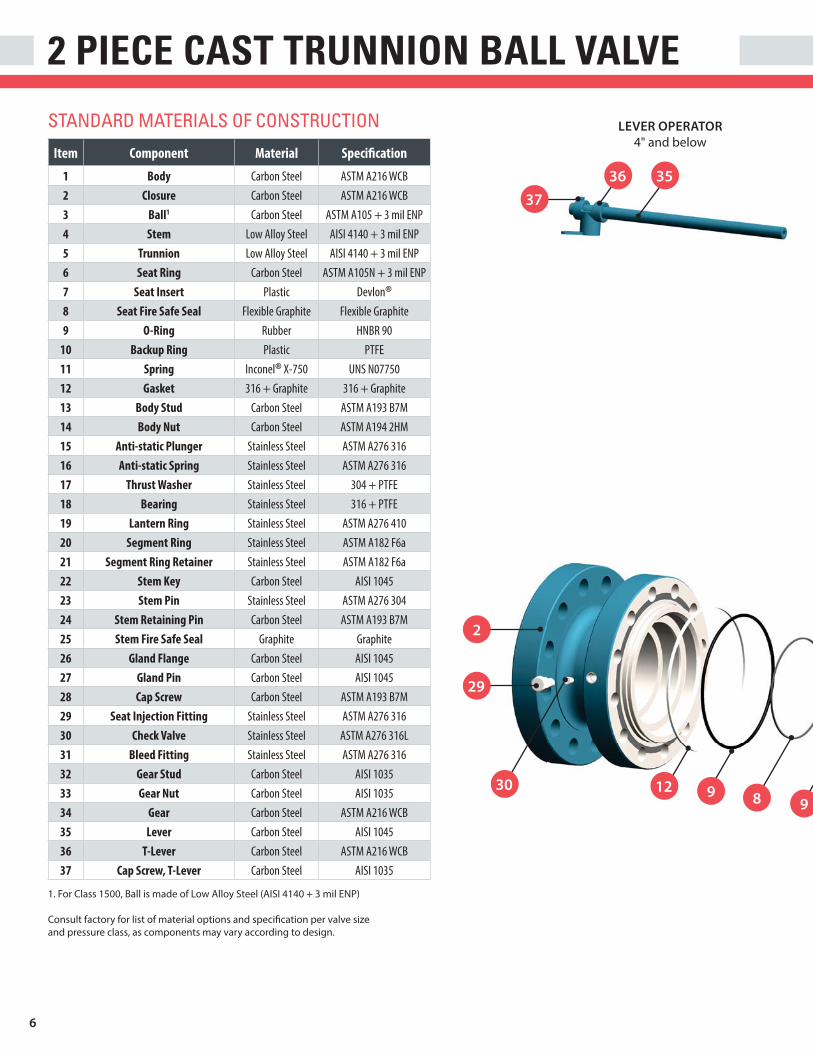
2 PIECE CAST TRUNNION BALL VALVE
STANDARD MATERIALS OF CONSTRUCTION LEVER OPERATOR
4" and below
35
37
36
128
2
29
30
99
1. For Class 1500, Ball is made of Low Alloy Steel (AISI 4140 + 3 mil ENP)
Consult factory for list of material options and specification per valve size
and pressure class, as components may vary according to design.
Item Component Material Specification
1 Body Carbon Steel ASTM A216 WCB
2 Closure Carbon Steel ASTM A216 WCB
3 Ball1 Carbon Steel ASTM A105 + 3 mil ENP
4 Stem Low Alloy Steel AISI 4140 + 3 mil ENP
5 Trunnion Low Alloy Steel AISI 4140 + 3 mil ENP
6 Seat Ring Carbon Steel ASTM A105N + 3 mil ENP
7 Seat Insert Plastic Devlon®
8 Seat Fire Safe Seal Flexible Graphite Flexible Graphite
9 O-Ring Rubber HNBR 90
10 Backup Ring Plastic PTFE
11 Spring Inconel® X-750 UNS N07750
12 Gasket 316 + Graphite 316 + Graphite
13 Body Stud Carbon Steel ASTM A193 B7M
14 Body Nut Carbon Steel ASTM A194 2HM
15 Anti-static Plunger Stainless Steel ASTM A276 316
16 Anti-static Spring Stainless Steel ASTM A276 316
17 Thrust Washer Stainless Steel 304 + PTFE
18 Bearing Stainless Steel 316 + PTFE
19 Lantern Ring Stainless Steel ASTM A276 410
20 Segment Ring Stainless Steel ASTM A182 F6a
21 Segment Ring Retainer Stainless Steel ASTM A182 F6a
22 Stem Key Carbon Steel AISI 1045
23 Stem Pin Stainless Steel ASTM A276 304
24 Stem Retaining Pin Carbon Steel ASTM A193 B7M
25 Stem Fire Safe Seal Graphite Graphite
26 Gland Flange Carbon Steel AISI 1045
27 Gland Pin Carbon Steel AISI 1045
28 Cap Screw Carbon Steel ASTM A193 B7M
29 Seat Injection Fitting Stainless Steel ASTM A276 316
30 Check Valve Stainless Steel ASTM A276 316L
31 Bleed Fitting Stainless Steel ASTM A276 316
32 Gear Stud Carbon Steel AISI 1035
33 Gear Nut Carbon Steel AISI 1035
34 Gear Carbon Steel ASTM A216 WCB
35 Lever Carbon Steel AISI 1045
36 T-Lever Carbon Steel ASTM A216 WCB
37 Cap Screw, T-Lever Carbon Steel AISI 1035

7
19
28
20
17
22
18
16
24
27
23
GEAR OPERATOR
4" and above
28
32
33
26
21
10
10
9
4
1
29
17
9
18
12
5
7610
14 13 31
9
11
3
3425
1615

8
FULL PORT DIMENSIONSIMPERIAL UNITS
ØB
E
F
ØD
A
ØC
g x ØH
L
J
ØK
I
M
Sizes 2” - 4”
Sizes 6” - 16”
Full Port Valve - Dimensions in Inches (in)
Size A ØB ØC ØD E F g x ØH I J ØK L MWeight
(lb)2" 7.00 6.00 1.94 1.94 4.29 0.71 4 x 3/4 3.23 - - - 19.69 363" 8.00 7.50 2.94 2.94 5.20 0.94 4 x 3/4 4.39 - - - 19.69 634" 9.00 9.00 3.94 3.94 6.22 1.38 8 x 3/4 5.20 7.64 13.78 8.72 19.69 1216" 15.50 11.00 5.94 5.94 8.94 2.17 8 x 7/8 7.24 10.51 13.78 9.43 - 2768" 18.00 13.50 7.94 7.94 10.39 2.56 8 x 7/8 8.90 12.80 23.62 14.27 - 432
10" 21.00 16.00 9.94 9.94 11.97 2.80 12 x 1 10.47 14.63 23.62 15.51 - 78312" 24.00 19.00 11.94 11.94 13.82 2.95 12 x 1 11.93 16.48 23.62 15.51 - 110714" 27.00 21.00 13.19 13.19 16.14 3.35 12 x 1-1/8 13.98 16.14 23.62 20.10 - 180816” 30.00 23.50 15.19 15.19 17.76 3.54 16 x 1-1/8 15.12 20.28 23.62 20.10 - 2061
CLASS 150
Full Port Valve - Dimensions in Inches (in)
Size A ØB ØC ØD E F g x ØH I J ØK L MWeight
(lb)2" 8.50 6.50 1.94 1.94 4.29 0.71 8 x 3/4 3.23 - - - 19.69 413" 11.12 8.25 2.94 2.94 5.20 0.94 8 x 7/8 4.39 - - - 19.69 804" 12.00 10.00 3.94 3.94 6.22 1.38 8 x 7/8 5.20 7.64 13.78 8.72 19.69 1596" 15.88 12.50 5.94 5.94 8.94 2.17 12 x 7/8 7.24 10.51 13.78 9.43 - 3338" 19.75 15.00 7.94 7.94 10.41 2.54 12 x 1 8.90 12.81 23.62 14.27 - 551
10" 22.38 17.50 9.94 9.94 12.40 2.80 16 x 1-1/8 10.47 15.06 23.62 15.51 - 93012" 25.50 20.50 11.94 11.94 14.33 2.95 16 x 1-1/4 12.72 16.99 23.62 15.51 - 132314" 30.00 23.00 13.19 13.19 16.54 3.35 20 x 1-1/4 14.76 16.54 23.62 20.10 - 200616" 33.00 25.50 15.19 15.19 18.31 4.33 20 x 1-3/8 15.51 20.83 23.62 20.10 - 2332
CLASS 300

9
Full Port Valve - Dimensions in Inches (in)
Size A ØB ØC ØD E F g x ØH I J ØK L MWeight
(lb)2" 11.50 6.50 1.94 1.94 5.51 1.38 8 x 3/4 4.25 - - - 19.69 753" 14.00 8.25 2.94 2.94 6.46 1.61 8 x 7/8 4.92 - - - 27.56 1214" 17.00 10.75 3.94 3.94 7.68 1.77 8 x 1 6.06 9.25 13.78 9.43 43.31 2946" 22.00 14.00 5.94 5.94 9.76 2.36 12 x 1-1/8 7.87 11.34 23.62 14.27 - 4928" 26.00 16.50 7.94 7.94 11.10 2.80 12 x 1-1/4 9.41 13.76 23.62 15.51 - 825
10" 31.00 20.00 9.94 9.94 12.87 2.95 16 x 1-3/8 11.54 15.04 18.31 14.17 - 131012" 33.00 22.00 11.94 11.94 15.35 4.33 20 x 1-3/8 13.62 17.87 23.62 20.10 - 1870
CLASS 600
Full Port Valve - Dimensions in Inches (in)
Size A ØB ØC ØD E F g x ØH I J ØK L MWeight
(lb)2" 14.50 8.50 1.94 1.94 5.51 1.38 8 x 1 4.45 - - - 27.56 1213" 15.00 9.50 2.94 2.94 6.46 1.61 8 x 1 5.12 - - - 43.31 1674" 18.00 11.50 3.94 3.94 7.68 1.77 8 x 1-1/4 6.26 9.25 13.78 9.43 55.12 3206" 24.00 15.00 5.94 5.94 9.76 2.64 12 x 1-1/4 8.74 12.42 23.62 15.51 - 649
CLASS 900
Full Port Valve - Dimensions in Inches (in)
Size A ØB ØC ØD E F g x ØH I J ØK L MWeight
(lb)2" 14.50 8.50 1.94 1.94 5.51 1.38 8 x 1 4.45 - - - 27.56 1213" 18.50 10.50 2.94 2.94 6.89 1.77 8 x 1-1/4 5.71 - - - 47.24 2514" 21.50 12.25 3.94 3.94 7.87 2.28 8 x 1-3/8 6.99 10.28 23.62 14.27 - 4166" 27.75 15.50 5.69 5.69 11.46 2.95 12 x 1-1/2 10.96 13.62 18.31 14.17 - 1179
CLASS 1500
NaNatutuuuuraral l GaGaaaas ss ss DiDiststtttriririririribububububub tititiononon CCCenene tetet rr
All weights listed are estimated.

10
REDUCED PORT DIMENSIONSIMPERIAL UNITS
Reduced Port Valve - Dimensions in Inches (in)
Size A ØB ØC ØD E F g x ØH I J ØK L MWeight
(lb)3 x 2 8.00 7.50 2.94 1.94 4.29 0.71 4 x 3/4 3.23 - - - 19.69 664 x 3 9.00 9.00 3.94 2.94 5.20 0.94 8 x 3/4 4.39 - - - 19.69 1046 x 4 15.50 11.00 5.94 3.94 6.22 1.38 8 x 7/8 5.20 7.64 13.78 8.72 19.69 1508 x 6 18.00 13.50 7.94 5.94 8.94 2.17 8 x 7/8 7.24 10.51 13.78 9.43 - 298
10 x 8 21.00 16.00 9.94 7.94 10.39 2.56 12 x 1 8.90 12.80 23.62 14.27 - 59112 x 10 24.00 19.00 11.94 9.94 11.97 2.80 12 x 1 10.47 14.63 23.62 15.51 - 1030
CLASS 150
Reduced Port Valve - Dimensions in Inches (in)
Size A ØB ØC ØD E F g x ØH I J ØK L MWeight
(lb)3 x 2 11.12 8.25 2.94 1.94 4.29 0.71 8 x 7/8 3.23 - - - 19.69 844 x 3 12.00 10.00 3.94 2.94 5.20 0.94 8 x 7/8 4.39 - - - 19.69 1326 x 4 15.88 12.50 5.94 3.94 6.22 1.38 12 x 7/8 5.20 7.64 13.78 8.72 19.69 2058 x 6 19.75 15.00 7.94 5.94 8.94 2.17 12 x 1 7.24 10.51 13.78 9.43 - 392
10 x 8 22.38 17.50 9.94 7.94 10.41 2.54 16 x 1-1/8 8.90 12.81 23.62 14.27 - 65012 x 10 25.50 20.50 11.94 9.94 12.40 2.80 16 x 1-1/4 10.47 15.06 23.62 15.51 - 1076
CLASS 300
ØB
E
F
ØD
A
ØC
M
Sizes 2” - 4”
g x ØH
L
J
ØK
I
Sizes 6” - 16”

11
Reduced Port Valve - Dimensions in Inches (in)
Size A ØB ØC ØD E F g x ØH I J ØK L MWeight
(lb)3 x 2 14.00 8.25 2.94 1.94 5.51 1.38 8 x 7/8 4.25 - - - 19.69 904 x 3 17.00 10.75 3.94 2.94 6.46 1.61 8 x 1 4.92 - - - 27.56 1546 x 4 22.00 14.00 5.94 3.94 7.68 1.77 12 x 1-1/8 6.06 9.25 13.78 9.43 43.31 3048 x 6 26.00 16.50 7.94 5.94 9.76 2.36 12 x 1-1/4 7.87 11.34 23.62 14.27 - 562
10 x 8 31.00 20.00 9.94 7.94 11.10 2.80 16 x 1-3/8 9.41 13.76 23.62 15.51 - 97012 x 10 33.00 22.00 11.94 9.94 12.87 2.95 20 x 1-3/8 11.54 15.04 18.31 14.17 - 1367
CLASS 600
Reduced Port Valve - Dimensions in Inches (in)
Size A ØB ØC ØD E F g x ØH I J ØK L MWeight
(lb)3 x 2 15.00 9.50 2.94 1.94 5.51 1.38 8 x 1 4.45 - - - 27.56 1834 x 3 18.00 11.50 3.94 2.94 6.46 1.61 8 x 1-1/4 5.12 - - - 43.31 2276 x 4 24.00 15.00 5.94 3.94 7.68 1.77 12 x 1-1/4 6.26 9.25 13.78 9.43 55.12 443
CLASS 900
Reduced Port Valve - Dimensions in Inches (in)
Size A ØB ØC ØD E F g x ØH I J ØK L MWeight
(lb)3 x 2 18.50 10.50 2.94 1.94 5.51 1.38 8 x 1-1/4 4.45 - - - 27.56 2164 x 3 21.50 12.25 3.94 2.94 6.89 1.77 8 x 1-3/8 5.71 - - - 47.24 3156 x 4 27.75 15.50 5.69 3.94 7.87 2.28 12 x 1-1/2 6.99 10.28 23.62 14.27 - 628
CLASS 1500
NaNatuturarararaaaal l lll GaGaGGGG s s ssss CoCoCoCoCoCoCompmpmpmpmpmpmpmpmpmprerrerereressssssssssioiioioion nn n StSStStatatatttttioiioii nn
All weights listed are estimated.

12
FULL PORT DIMENSIONSMETRIC UNITS
Full Port Valve - Dimensions in Millimeters (mm)
Size
(DN)A ØB ØC ØD E F g x ØH I J ØK L M
Weight
(kg)50 178 150 49 49 109 18 4 x 19 82 - - - 500 1680 203 190 74 74 132 24 4 x 19 111.5 - - - 500 28
100 229 230 100 100 158 35 8 x 19 132 194 350 221.5 500 55150 394 280 150 150 227 55 8 x 22 184 267 350 239.5 - 125200 457 345 201 201 264 65 8 x 22 226 325 600 362.5 - 196250 533 405 252 252 304 71 12 x 25 266 371.5 600 394 - 355300 610 485 303 303 351 75 12 x 25 303 418.5 600 394 - 502350 686 535 334 334 410 85 12 x 29 355 410 600 510.5 - 820400 762 595 385 385 451 90 16 x 29 384 515 600 510.5 - 935
CLASS 150
Full Port Valve - Dimensions in Millimeters (mm)
Size
(DN)A ØB ØC ØD E F g x ØH I J ØK L M
Weight
(kg)50 216 165 49 49 109 18 8 x 19 82 - - - 500 1880 283 210 74 74 132 24 8 x 22 111.5 - - - 500 36
100 305 255 100 100 158 35 8 x 22 132 194 350 221.5 500 72150 403 320 150 150 227 55 12 x 22 184 267 350 239.5 - 151200 502 380 201 201 264.5 64.5 12 x 25 226 325.5 600 362.5 - 250250 568 445 252 252 315 71 16 x 29 266 382.5 600 394 - 422300 648 520 303 303 364 75 16 x 32 323 431.5 600 394 - 600350 762 585 334 334 420 85 20 x 32 375 420 600 510.5 - 910400 838 650 385 385 465 110 20 x 35 394 529 600 510.5 - 1058
CLASS 300
ØB
E
F
ØD
A
ØC
g x ØH
L
J
ØK
I
M
Sizes 2” - 4”
Sizes 6” - 16”

13
Full Port Valve - Dimensions in Millimeters (mm)
Size
(DN)A ØB ØC ØD E F g x ØH I J ØK L M
Weight
(kg)50 292 165 49 49 140 35 8 x 19 108 - - - 500 3480 356 210 74 74 164 41 8 x 22 125 - - - 700 55
100 432 275 100 100 195 45 8 x 25 154 235 350 239.5 1100 133150 559 355 150 150 248 60 12 x 29 200 288 600 362.5 - 223200 660 420 201 201 282 71 12 x 32 239 349.5 600 394 - 374250 787 510 252 252 327 75 16 x 35 293 382 465 360 - 594300 838 560 303 303 390 110 20 x 35 346 454 600 510.5 - 848
CLASS 600
Full Port Valve - Dimensions in Millimeters (mm)
Size
(DN)A ØB ØC ØD E F g x ØH I J ØK L M
Weight
(kg)50 368 215 49 49 140 35 8 x 25 113 - - - 700 5580 381 240 74 74 164 41 8 x 25 130 - - - 1100 76
100 457 290 100 100 195 45 8 x 32 159 235 350 239.5 1400 145150 610 380 150 150 248 67 12 x 32 222 315.5 600 394 - 295
CLASS 900
Full Port Valve - Dimensions in Millimeters (mm)
Size
(DN)A ØB ØC ØD E F g x ØH I J ØK L M
Weight
(kg)50 368 215 49 49 140 35 8 x 25 113 - - - 700 5580 470 265 74 74 175 45 8 x 32 145 - - - 1200 114
100 546 310 100 100 200 58 8 x 35 177.5 261 600 362.5 - 189150 705 395 144 144 291 75 12 x 38 278.5 346 465 360 - 535
CLASS 1500
PiPiPiiiPipepppppeeeep lilil nenenes ss nenen arar RRefiefineneryryry
All weights listed are estimated.

14
REDUCED PORT DIMENSIONSMETRIC UNITS
Reduced Port Valve - Dimensions in Millimeters (mm)
Size
(DN)A ØB ØC ØD E F g x ØH I J ØK L M
Weight
(kg)80 x 50 203 190 74 49 109 18 4 x 19 82 - - - 500 30
100 x 80 229 230 100 74 132 24 8 x 19 111.5 - - - 500 47150 x 100 394 280 150 100 158 35 8 x 22 132 194 350 221.5 500 68200 x 150 457 345 201 150 227 55 8 x 22 184 267 350 239.5 - 135250 x 200 533 405 252 201 264 65 12 x 25 226 325 600 362.5 - 268300 x 250 610 485 303 252 304 71 12 x 25 266 371.5 600 394 - 467
CLASS 150
Reduced Port Valve - Dimensions in Millimeters (mm)
Size
(DN)A ØB ØC ØD E F g x ØH I J ØK L M
Weight
(kg)80 x 50 283 210 74 49 109 18 8 x 22 82 - - - 500 38
100 x 80 305 255 100 74 132 24 8 x 22 111.5 - - - 500 60150 x 100 403 320 150 100 158 35 12 x 22 132 194 350 221.5 500 93200 x 150 502 380 201 150 227 55 12 x 25 184 267 350 239.5 - 178250 x 200 568 445 252 201 264.5 64.5 16 x 29 226 325.5 600 362.5 - 295300 x 250 648 520 303 252 315 71 16 x 32 266 382.5 600 394 - 488
CLASS 300
ØB
E
F
ØD
A
ØC
M
Sizes 2” - 4”
g x ØH
L
J
ØK
I
Sizes 6” - 16”

15
Reduced Port Valve - Dimensions in Millimeters (mm)
Size
(DN)A ØB ØC ØD E F g x ØH I J ØK L M
Weight
(kg)80 x 50 356 210 74 49 140 35 8 x 22 108 - - - 500 41
100 x 80 432 275 100 74 164 41 8 x 25 125 - - - 700 70150 x 100 559 355 150 100 195 45 12 x 29 154 235 350 239.5 1100 138200 x 150 660 420 201 150 248 60 12 x 32 200 288 600 362.5 - 255250 x 200 787 510 252 201 282 71 16 x 35 239 349.5 600 394 - 440300 x 250 838 560 303 252 327 75 20 x 35 293 382 465 360 - 620
CLASS 600
Reduced Port Valve - Dimensions in Millimeters (mm)
Size
(DN)A ØB ØC ØD E F g x ØH I J ØK L M
Weight
(kg)80 x 50 381 240 74 49 140 35 8 x 25.4 113 - - - 700 83
100 x 80 457 290 100 74 164 41 8 x 32 130 - - - 1100 103150 x 100 610 380 150 100 195 45 12 x 32 159 235 350 239.5 1400 201
CLASS 900
Reduced Port Valve - Dimensions in Millimeters (mm)
Size
(DN)A ØB ØC ØD E F g x ØH I J ØK L M
Weight
(kg)80 x 50 470 265 74 49 140 35 8 x 32 113 - - - 700 98
100 x 80 546 310 100 74 175 45 8 x 35 145 - - - 1200 143150 x 100 705 395 144 100 200 58 12 x 38 177.5 261 600 362.5 - 285
CLASS 1500
StStStttStStStSSSttorororororrorrrorrororooragagagagagagagagagagagagaaaagagggage e ee e e eeeeeee eee e TaTaTaaTaTaTaTaTaTaTaTaTaT nknknknkkkkkkkknknknknkknknknknnkk FFFFFFFFFFFFFFFFFFFFacacacacacacacacaccccililllililililililiiiililitititititititititititititiityyyyyyyyyyyyyyyyyy
All weights listed are estimated.

16
ACTUATOR MOUNTING DIMENSIONSIMPERIAL UNITS
n x ØP
ØR
Q
T
ØSW
n = Number of Bolts
ØP = Hole Diameter
Q = Min. Flange Thickness
ØR = Bolt Circle Diameter
ØS = Stem Diameter
T = Stem Diameter Over Keys
W = Key Width
ISO 5211 Flange in Inches (in)
Size ISO n ØP Q ØR ØS T W2" F10 4 0.47 0.47 4.02 0.79 0.98 0.243" F10 4 0.47 0.47 4.02 0.94 1.18 0.314" F12 4 0.55 0.59 4.92 1.26 1.50 0.396" F16 4 0.87 0.98 6.50 1.57 1.81 0.478" F16 4 0.87 0.98 6.50 1.97 2.24 0.55
10" F25 8 0.71 0.98 10.00 2.36 2.68 0.7112" F25 8 0.71 0.98 10.00 2.76 3.11 0.7914" F25 8 0.71 0.98 10.00 2.87 3.23 0.7916" F25 8 0.71 0.98 10.00 2.87 3.23 0.79
CLASS 150
ISO 5211 Flange in Inches (in)
Size ISO n ØP Q ØR ØS T W2" F10 4 0.47 0.47 4.02 0.79 0.98 0.243" F10 4 0.47 0.47 4.02 0.94 1.18 0.314" F12 4 0.55 0.59 4.92 1.26 1.50 0.396" F16 4 0.87 0.98 6.50 1.57 1.81 0.478" F16 4 0.87 0.98 6.50 1.97 2.24 0.55
10" F25 8 0.71 0.98 10.00 2.36 2.68 0.7112" F25 8 0.71 0.98 10.00 2.76 3.11 0.7914" F25 8 0.71 0.98 10.00 2.87 3.23 0.7916" F25 8 0.71 0.98 10.00 3.15 3.54 0.87
CLASS 300
ISO 5211 Flange in Inches (in)
Size ISO n ØP Q ØR ØS T W2" F12 4 0.55 0.59 4.92 1.18 1.42 0.313" F14 4 0.71 0.79 5.51 1.42 1.65 0.394" F16 4 0.87 0.98 6.50 1.69 1.93 0.476" F16 4 0.87 0.98 6.50 1.97 2.24 0.558" F25 8 0.71 0.98 10.00 2.36 2.68 0.71
10" F25 8 0.71 0.98 10.00 2.76 3.11 0.7912" F25 8 0.71 0.98 10.00 3.15 3.54 0.87
CLASS 600
ISO 5211 Flange in Inches (in)
Size ISO n ØP Q ØR ØS T W2" F12 4 0.55 0.59 4.92 1.18 1.42 0.313" F14 4 0.71 0.79 5.51 1.42 1.65 0.394" F16 4 0.87 0.98 6.50 1.69 1.93 0.476" F16 4 0.87 0.98 6.50 2.09 2.40 0.63
CLASS 900
ISO 5211 Flange in Inches (in)
Size ISO n ØP Q ØR ØS T W2" F12 4 0.55 0.59 4.92 1.18 1.42 0.313" F16 4 0.87 0.98 6.50 1.69 1.93 0.474" F16 4 0.87 0.98 6.50 1.97 2.24 0.556" F25 8 0.71 0.98 10.00 2.44 2.76 0.71
CLASS 1500
Data contained above based on ball bore size and not end flange bore size.

17
ACTUATOR MOUNTING DIMENSIONSMETRIC UNITS
ISO 5211 Flange in Millimeters (mm)
Size
(DN)ISO n ØP Q ØR ØS T W
50 F10 4 12 12 102 20 25 680 F10 4 12 12 102 24 30 8
100 F12 4 14 15 125 32 38 10150 F16 4 22 25 165 40 46 12200 F16 4 22 25 165 50 57 14250 F25 8 18 25 254 60 68 18300 F25 8 18 25 254 70 79 20350 F25 8 18 25 254 73 82 20400 F25 8 18 25 254 73 82 20
CLASS 150
ISO 5211 Flange in Millimeters (mm)
Size
(DN)ISO n ØP Q ØR ØS T W
50 F10 4 12 12 102 20 25 680 F10 4 12 12 102 24 30 8
100 F12 4 14 15 125 32 38 10150 F16 4 22 25 165 40 46 12200 F16 4 22 25 165 50 57 14250 F25 8 18 25 254 60 68 18300 F25 8 18 25 254 70 79 20350 F25 8 18 25 254 73 82 20400 F25 8 18 25 254 80 90 22
CLASS 300
ISO 5211 Flange in Millimeters (mm)
Size
(DN)ISO n ØP Q ØR ØS T W
50 F12 4 14 15 125 30 36 880 F14 4 18 20 140 36 42 10
100 F16 4 22 25 165 43 49 12150 F16 4 22 25 165 50 57 14200 F25 8 18 25 254 60 68 18250 F25 8 18 25 254 70 79 20300 F25 8 18 25 254 80 90 22
CLASS 600
ISO 5211 Flange in Millimeters (mm)
Size
(DN)ISO n ØP Q ØR ØS T W
50 F12 4 14 15 125 30 36 880 F14 4 18 20 140 36 42 10
100 F16 4 22 25 165 43 49 12150 F16 4 22 25 165 53 61 16
CLASS 900
ISO 5211 Flange in Millimeters (mm)
Size
(DN)ISO n ØP Q ØR ØS T W
50 F12 4 14 15 125 30 36 880 F16 4 22 25 165 43 49 12
100 F16 4 22 25 165 50 57 14150 F25 8 18 25 254 62 70 18
CLASS 1500
n x ØP
ØR
Q
T
ØSW
Data contained above based on ball bore size and not end flange bore size.
n = Number of Bolts
ØP = Hole Diameter
Q = Min. Flange Thickness
ØR = Bolt Circle Diameter
ØS = Stem Diameter
T = Stem Diameter Over Keys
W = Key Width

18
TECHNICAL DATA
PRESSURE RATINGSMaterial Maximum Pressure Rating by Class
ClassCarbon Steel Low Temp Carbon Steel Stainless Steel
psig bar psig bar psig bar150 285 20 290 20 275 19300 740 51 750 52 720 50600 1480 102 1500 103 1440 99900 2220 153 2250 155 2160 149
1500 3705 255 3750 259 3600 248
Temperature Range -20 to 100oF (-29 to 38oC)
Break Torque in Inch Pounds (in-lb)
Size CL 150 CL 300 CL 600 CL 900 CL 15002" 354 620 1018 2655 26553" 797 1062 1593 3983 57534" 1239 2478 3098 6196 97366" 3585 5133 8408 14161 247828" 6638 9736 15046 - -
10" 11506 15931 26552 - -12" 15931 23012 39828 - -14" 19472 30978 - - -16" 30978 39828 - - -
OPERATING TORQUEBreak Torque in Newton Meters (Nm)
Size (DN) CL 150 CL 300 CL 600 CL 900 CL 150050 40 70 115 300 30080 90 120 180 450 650
100 140 280 350 700 1100150 405 580 950 1600 2800200 750 1100 1700 - -250 1300 1800 3000 - -300 1800 2600 4500 - -350 2200 3500 - - -400 3500 4500 - - -
Devlon seat material used in calculating operating torque values.
The above values are new valve torque values, at maximum differential pressure.
The run (operating) torque is 45% of break torque. Closing torque is 75% of break torque.
The above torque values do not contain service factors.
When selecting an actuator, add 25% safety factor to the required torque as a minimum.
For sizes not listed, contact factory.
Actuator selection should be made on customer experience and appropriate service factors.
CV FOR FULL PORT BALLCv Value of Full Port Ball Valve
SizeCL 150 CL 300 CL 600 CL 900 CL 1500
in DN2" 50 420 420 420 330 3303" 80 1200 1200 1200 910 8204" 100 2200 2200 2200 1800 17006" 150 5150 5150 4400 4380 38008" 200 9500 9500 8450 - -
10" 250 15000 15000 14700 - -12" 300 23000 23000 22550 - -14" 350 28000 28000 - - -16" 400 37200 37200 - - -
Cv Value of Reduced Port Ball Valve
SizeCL 150 CL 300 CL 600 CL 900 CL 1500
in DN3 x 2 80 x 50 200 200 200 190 1804 x 3 100 x 80 600 600 600 590 5506 x 4 150 x 100 800 800 790 790 7808 x 6 200 x 150 2150 2150 2150 - -
10 x 8 250 x 200 4300 4300 4300 - -12 x 10 300 x 250 7550 7550 7550 - -
CV FOR REDUCED PORT BALL

19
TECHNICAL DATASEAT PERFORMANCE CAPABILITIES
4000
3500
3000
2500
276
241
207
172
2000
1500
1000
500
0
138
103
69
34
0
-148 0 50 100 150 200 250 300 350 400 450
(-100) (-18) (10) (38) (66) (121) (149) (177) (204) (232) (260) (288)
500 550 600°F
(93) (316°C)
Class 1500 CS Body
Class 900 CS Body
Class 600 CS Body
Class 300 CS Body
Class 150 CS Body
Devlon® PEEK
Pre
ssu
re (
ba
r)
Pre
ssu
re (p
sig
)
Temperature °F (°C)
TFM 1600
Material Temperature Limits
Material SpecificationFahrenheit (°F) Celsius (°C)
Min. Max. Min. Max.
Body
Carbon Steel ASTM A216 WCB -20 800 -29 427Low Temp Carbon Steel ASTM A352 LCC -50 650 -46 343
Stainless Steel ASTM A351 CF8M -425 1500 -254 816
Seat TFM 1600 TFM 1600 -148 450 -100 232
Devlon® Devlon® -50 350 -46 177PEEK PEEK -148 500 -100 260
Seal HNBR 90 HNBR 90 -50 302 -46 150
Viton® GLT 90 Viton® GLT 90 -50 392 -46 200
TEMPERATURE LIMITS
Standard valve configurations use seals compatible with temperatures down to -40°F (-40°C).
Trim Options & Materials
ComponentCarbon Steel Low Temp Carbon Steel Stainless Steel
Trim 3 Trim 4 Trim 5Ball ASTM A105 /AISI 4140 + 3 mil ENP1 ASTM A350 LF2/AISI 4140 + 3 mil ENP1 ASTM A182 F316/F512
Stem AISI 4140 + 3 mil ENP AISI 4140 + 3 mil ENP ASTM A182 F51Trunnion AISI 4140 + 3 mil ENP AISI 4140 + 3 mil ENP ASTM A182 F51Seat Ring ASTM A105 + 3 mil ENP ASTM A350 LF2 + 3 mil ENP ASTM A182 F316
TRIM OPTIONS
1 For Class 1500, Ball is made of Low Alloy Steel (AISI 4140 + 3mil ENP)
2 For Class 1500, Ball is made of Duplex Stainless Steel (ASTM A182 F51)

20
Place and date: For the issuing office: Katy, TX, 12, November, 2015 DNV GL – Business Assurance
1400 Ravello Drive, Katy, TX, 77449-5164, USA
John C Stefan Management Representative
Lack of fulfilment of conditions as set out in the Certification Agreement may render this Certificate invalid. ACCREDITED UNIT: DNV GL Business Assurance USA, Inc., 1400 Ravello Drive, Katy, TX 77449 USA. TEL:281-396-1000. dnvglcert.com
Certificate No: 189874-2015-AQ-USA-ANAB
Initial certification date: 12, November, 2015
Valid: 12, November, 2015 - 11, March, 2017
This is to certify that the management system of
C & C Industries 10350 Clay Road #300, Houston, TX, 77041, USA
has been found to conform to the Quality Management System standard: ISO 9001:2008
This certificate is valid for the following scope: The Purchase and Distribution of Valves and Fittings for the Pipe, Valve and Fittings Industries
OUR SERVICE CAPABILITIES
WHAT YOU NEED. WHEN YOU NEED IT. Our extensive product and application expertise allows us to be
more than just a supplier. Our customers view us as the people
they trust to integrate flow controls with their equipment and
ensure the successful achievement of their project goals. Our
increased involvement with a diverse range of projects, spanning
an array of industries provides us with a multitude of references
for successful integration.
People• Product and Application Know-How
• Technically Trained Sales Staff
• Exceptional Customer Service
Products• Ball, Butterfly, Check, Gate, Needle and Plug Valves
• Adapters, Fittings, Gaskets, Joints, Manifolds, Seals and
Unions
• Product Leadership — Quality, Reliable and Innovative
Products
• Replacement and Spare Parts
• ISO 9001:2008 Certified Organization
Services• Distribution Network Located throughout North, Central and
South America
• Customer Specific Labeling and Packaging
• Strategic Account Partnerships
• Express Delivery
• Quality and Materials Assurance
• Valve Customization and Automation
VALVE QUALITY DEVELOPMENT TEAMBefore the decision is made to brand a product C&C, our
Valve Quality Development Team conducts comprehensive
manufacturers audits and inspections on both the product and
the manufacturer’s production process. These stringent audits
and inspections ensure the manufacturer’s ability to produce
and provide products of consistent quality demanded by our
customers and in accordance with documented procedures. Once
manufacturers are qualified, the VQDT performs onsite witnessing
and inspections of the product prior to releasing it for shipment.
This added capability and oversight differentiates us from other
suppliers.
Reports providing proof of quality and testing are available to our
customers. Additional tests can be provided upon request.
• Positive Material Identification
• Material Test Reports
• Dye Penetrant Testing
• Quality and Technical Documentation
• Supplementary Testing per Customer RequirementsProof of Product Quality and Compliance
API 6D Pressure Test Capability

21
COMPLETE AUTOMATION SOLUTIONS Our company is partnered with many of the largest and
most successful valve and actuator manufacturers in the
world. These relationships allow us to competently and
competitively provide the valve/actuator/accessory packages
that you require. Taking it one step further, we are able to
marry products we represent with those we don’t and, as a
result, provide you with a complete, fully customized flow
control solution.
In order to best serve our customers, we have partnered
with the industries’ top manufacturers to provide a complete
range of valve automation services to keep your process up
and running.
• Actuators
• Limit Switches
• Solenoid Valves
• Position Monitors and Transmitters
• Mounting Kits
ADDITIONAL API 6D OFFERINGSPiston Check Valve - Guardian SeriesThe C&C Cast Piston Check Valve provides system protection through back flow control. It is used in applications where there
is a need to reduce excessive wear associated with reciprocating service, such as with compressors and pumps. The Piston
Check is outfitted with a top entry flange, allowing for ease of maintenance and repair of internal parts, ultimately reducing
downtime.
• Sizes 2” to 12”, ASME Class 150 through 1500
• Suitable for Liquid or Gaseous Applications
• NACE MR0175/ISO 15156-1
• API 6D Monogrammed, ISO 14313, CSA Z245.15-17
• PED 2014/68/EU Annex III, Module H
• Material Traceability to ASME B31.1
3 Piece Forged Trunnion Ball Valve - Trident SeriesThe C&C 3 piece Forged Trunnion Mounted Ball Valve is ideally suited for pipeline and other applications within the global
energy infrastructure where zero leakage positive shutoff is critical. API Monogrammed and compliant with all relevant
industry specifications, C&C trunnion ball valves should be an integral component of your piping network.
• Sizes 2” to 36”, ASME Class 150 through 2500
• API 6D Monogrammed, ISO 14313, CSA Z245.15-17
• NACE MR0175/ISO 15156-1
• PED 2014/68/EU Annex III, Module H
• Compliant with ASME B16.5, B16.10 and ISO 5211
• Material Traceability to ASME B31.1
• Fire Safe: API6FA/API 607 7th Edition
Dual Expanding Plug ValveThe VE® Dual Expanding plug valve was developed to replace the practice of using two inline valves with a drain and/or bleed
valve. Traditional gate valves and other valve combinations degrade over time and result in loss of product and frequent
maintenance. The special design of the dual expanding plug valve’s sealing mechanism minimizes wear, providing long lasting
and safe, zero leakage flow control solution. Available in several different bleed system configurations in conjunction with a
pressure relief device, this all in one valve not only meets API 6D requirements, but also provides a space saving, reliable and
economical solution.
• Sizes 2” to 36”, ASME Class 150 through 600
• Fugitive Emissions (ISO 15848-1), Fire Safe (API 607), PED
(PED 97/23/EC) and ATEX (ATEX 94/23/EC CAT II 3 G/D T1
to T4) Certified
• All Wetted Parts - ENP Protection
• Permanent Integral Thermal Relief and Bleed Function
• Ease of Inline Maintenance in Case of Seal Replacement
• Double Isolation Function According to API 6D/ISO14313
In House Valve Modifications

22
NOTES

23

The contents of this publication are presented for
informational purposes only, and while every effort
has been made to ensure their accuracy, they are
not to be construed as warranties or guarantees,
expressed or implied, regarding the products or
services described herein or their use or applicability.
© 2018 CNC Flow Control
_CAT_API6D_ PTRUNBV_022018
local distributor/agent
WORLDWIDE P R O V I D E R O F INNOVATIVE, HIGH QUALITY VALVES
10350 Clay Road, Suite 250 Houston, TX 77041Toll Free: (844) 398-6449
Calgary Place – Bldg 1850-330 5 Ave SWCalgary, AB T2P 0L4Phone: (403) 930-1930