TRUE UNION DIAPHRAGM VALVE TYPE14 BALL … Recently along with the increasingly high integration of...
11
149 Asahi AV HIGH PURITY SERIES TRUE UNION DIAPHRAGM VALVE TYPE14 ( LF ) 152 BALL VALVE TYPE21 ( LF ) 154 LAB COCK ( LF ) 158 HP-PVC PIPE & FITTINGS 160 HP-PVC FITTINGS 160 AV PREFAB JOINT<UNION> 165 AV FLANGE<HP-PVC> 165 MULTI-JOINT 166 AV GASKET 167 ASAHI AV HIGH PURITY SERIES ( HP-PVC ) The specifications in this brochure are subject to change without prior notice due to improvements and modifications. *LF : Lubricant Free TRUE UNION DIAPHRAGM VALVE TYPE14 BALL VALVE TYPE21 PANEL MOUNTING LAB COCK HP-PVC PIPES & FITTINGS HP-PVC FITTINGS AV PREFAB JOINT AV FLANGE MULTI-JOINT AV GASKET 149
Transcript of TRUE UNION DIAPHRAGM VALVE TYPE14 BALL … Recently along with the increasingly high integration of...

149
Asahi AV HIGH PURITY SERIESTRUE UNION DIAPHRAGM VALVE TYPE14 (LF) 152BALL VALVE TYPE21 (LF) 154LAB COCK (LF) 158HP-PVC PIPE & FITTINGS 160HP-PVC FITTINGS 160AV PREFAB JOINT<UNION> 165AV FLANGE<HP-PVC> 165MULTI-JOINT 166AV GASKET 167
ASAHI AV HIGH PURITY SERIES(HP-PVC)
The specifications in this brochure are subject to change without prior notice due to improvements and modifications.
*LF : Lubricant Free
TRUE
UNION
DIAP
HRAG
MVA
LVE T
YPE1
4BA
LL V
ALVE
TYP
E21
PANE
L MO
UNTI
NGLA
B CO
CKHP
-PVC
PIP
ES&
FITT
INGS
HP-P
VC F
ITTI
NGS
AV P
REFA
B JO
INT
AV F
LANG
EMU
LTI-J
OINT
AV G
ASKE
T
149

Recently along with the increasingly high integration of semiconductors, stricter cleanliness is required of wafer surfaces from the viewpoint of product yield. Consequently, the role of cleaning processes is becoming more and more important.
Since the final washing of wafers of waters uses ultrapure water the cleanliness of wafers depends heavily on the quality of the ultrapure water. There fore, it is essential to improve the process lines used for the production of ultrapure water. We have an assortment of plastic piping materials that elute fewer metal ions and TOC and have finer inner surfaces. They fully accommodate the requirements of semicon-ductor manufacture, such as for 1MD-RAM, 4MD-RAM, and 16MD-RAM.
Ultrapure Water
High Purity SeriesHigh Purity Series
FEATURESFEATURESFEATURES• Minimized Leachable.• Mirror-smooth inner surfaces.• Dead space minimized to prevent residence of liquid.• Purified articles controlled under strict rules: degreasing and washing,
forced drying with nitrogen, assembly, and packaging are carried out in a clean room.
• Easy, dependable installation and removal. Easy to maintain and clean.
• Unrivaled mechanical strength and reliabillity.
Range of Nominal Size and Materials
Type TRUE UNION DIAPHRAGM VALVE TYPE 14Body Materials PVC C-PVC PP PVDFEnd Connectors
Threaded Socket Threaded Socket(welded) Threaded Socket Threaded Socket
(welded) Spigot
Nom
inal
Siz
e mm inch15 1/2 ○ ○ ○ ○ ○ ○ ○ ○ ○20 3/4 ○ ○ ○ ○ ○ ○ ○ ○ ○25 1 ○ ○ ○ ○ ○ ○ ○ ○ ○32 1 1/4 ○ ○ ○ ○ ○ ※○ ○ ○ ○40 1 1/2 ○ ○ ○ ○ ○ ○ ○ ○ ○50 2 ○ ○ ○ ○ ○ ○ ○ ○ ○Page 152 - 153
Type BALL VALVE TYPE 21Body Materials PVC C-PVC PP PVDFEnd Connectors Flanged Threaded Socket Flanged Threaded Socket
(welded) Flanged Threaded Socket Flanged Threaded Socket(welded) Spigot
Nom
inal
Siz
e
mm inch15 1/2 ○ ○ ○ ○ ○ ○ ○ ○ ○ ○ ○ ○ ○20 3/4 ○ ○ ○ ○ ○ ○ ○ ○ ○ ○ ○ ○ ○25 1 ○ ○ ○ ○ ○ ○ ○ ○ ○ ○ ○ ○ ○32 1 1/4 ○ ○ ○ ○ ○ ○ ○ ○ ○※ ○ ○ ○ ○40 1 1/2 ○ ○ ○ ○ ○ ○ ○ ○ ○ ○ ○ ○ ○50 2 ○ ○ ○ ○ ○ ○ ○ ○ ○ ○ ○ ○ ○65 2 1/2 ○ ○ ○ ○ ○ ○ ○ ○ ○ ○ ○ ○ ○80 3 ○ ○ ○ ○ ○ ○ ○ ○ ○ ○ ○ ○ ○
100 4 ○ ○ ○ ○ ○ ○ ○ ○ ○ ○ ○ ○ ○Page 154 - 157
Type LAB COCKBody
Materials PVC
End Connectors
Male Thread, Female Thread, Hose
Nominal Size
Male Thread1/4 1/2
Female Thread1/4 3/8
Page 158 - 159
Nom
inal
Siz
e
mm inch Pipe Elbow(L)
90°AV Bend
45°Elbow (45L)
45°AV Bend
Socket(S) Tee(T) Faucet
Elbow(FL)Valve
Socket(VS)Faucet
Socket(FS)Cap(C)
13 1 1/2 ○ ○ ○ - - - - ○ ○ ○ -16 2 ○ ○ ○ - - - - ○ ○ ○ ○20 2 1/2 ○ ○ ○ - - - - ○ ○ ○ -25 3 ○ ○ ○ - - - - ○ ○ ○ ○30 4 ○ ○ ○ - - - - ○ ○ ○ ○40 5 ○ ○ ○ - - - - ○ ○ ○ ○50 6 ○ ○ ○ - - - - ○ ○ ○ ○65 8 ○ ○ ○ - - - - ○ ○ ○ ○75 10 ○ ○ ○ - - - - ○ ○ ○ ○
100 12 ○ ○ ○ - - - - ○ ○ ○ -125 14 ○ ○ ○ - - - - ○ ○ ○ -150 16 - - - ○ ○ - - - ○ ○ -200 18 - - - - - ○ ○ - ○ ○ -250 20 - - - - - ○ ○ - ○ ○ -
Page 160 161 162-163 164
※Except for JIS standard.
※ ※
※ ※※
●AV Valves
●Pipe & Fittings
Nom
inal
Siz
e
mm ReducingSocket(RS)
ReducingTee(RT)
16×13 ○20×13 ○ ○20×16 ○ ○25×13 ○ ○25×16 ○ ○25×20 ○ ○30×16 ○30×25 ○ ○40×13 ○40×20 ○ ○40×25 ○ ○40×30 ○ ○50×13 ○50×20 ○ ○50×25 ○ ○50×40 ○ ○65×40 ○65×50 ○ ○75×25 ○75×40 ○75×50 ○ ○75×65 ○
100×75 ○ ○125×75 ○
125×100 ○ ○150×75 ○
150×100 ○150×125 ○ ○200×75 ○
200×100 ○200×150 ○ ○250×75 ○
250×100 ○250×100 ○ ○Page 162 163
151150

152
HIGH PURITY SERIES
153
HIGH PURITY SERIES
TRUE UNION DIAPHRAGM VALVE TYPE 14 15mm - 50mm(1/2inch - 2inch)
(For details, refer to 〈CHEMICAL RESISTANCE ON ASAHI AV VALVE〉T-001
MATERIAL AND WORKING TEMPERATURE
Body material Nominal sizemm(inch)
WorkingTemperature ℃(˚F)
Max. Working Pressure at 20℃(70 F゚)
MPa{kgf/cm2}[PSI]End Connectors
Unplasticized Polyvinyl Chloride(PVC) 15 - 50(1/2 - 2) 0 - 50(30 - 120) 1.0{10.2}[150] Socket End. Threaded End Chlorinated Polyvinyl Chloride(C-PVC) 15 - 50(1/2 - 2) 0 - 90(30 - 195) 1.0{10.2}[150] Socket End. Threaded End Polypropylene(PP) 15 - 50(1/2 - 2) -20 - 80(-5 - 175) 1.0{10.2}[150] Socket End. Threaded End Polyvinylidene Fluoride(PVDF) 15 - 50(1/2 - 2) -20 - 100(-5 - 210) 1.0{10.2}[150] Socket End. Threaded End. Spiqot End
■ Easy MaintenanceThe valve body can be removed from the pipe line by loosening the union nuts at both its ends.
FEATURES
PARTS & MATERIALS
*With PTFE Diaphragm
No. DESCRIPTION Pcs. MATERIAL No. DESCRIPTION Pcs. MATERIAL
① BODY1
BODY/BONNET PVC/PVC C-PVC/PP PP/PP PVDF/PPG PVDF/PVDF
⑪ GAUGE COVER 1 PC⑫ NAME PLATE 1 PVC
② BONNET⑬ RETAINING RING-C TYPE 1 STAINLESS STEEL304⑭ O-RING(A) 1 EPDM
③ DIAPHRAGM 1
EPDM IIR NBR,CSM CPE,FKM VIFLON C(FKM-C) VIFLON F(FKM-F) PTFE
⑮ O-RING(B) 1 EPDM⑯ THRUST RING(A) 1 UHMWPE⑰ THRUST RING(B) 1 UHMWPE⑱ BOLT・NUT 4 STAINLESS STEEL304
○3a INSERTED METAL OF DIAPHRAGM 1 STAINLESS STEEL304
⑳ STOPPER 1 COPPER ALLOY(C3604)○21 SCREW 1 STAINLESS STEEL304
④ CUSHION 1 EPDM*○25 ENDCONNECTOR 2
PVC C-PVC PP PVDF
⑥ COMPRESSOR 1 PVDF⑦ JOINT 1 STAINLESS STEEL304 ○26 UNION NUT 2⑧ STEM 1 COPPER ALLOY(C3604)
○27 O-RING(C) 2 EPDM FKM Others
⑨ SLEEVE 1 COPPER ALLOY(C3604)⑩ HAND WHEEL 1 PP
DIMENTIONS TABLEJIS Unit:mm
Nominal Size d
Socket End Threaded End Spigot End
D D1 D2C(LIFT)
H H1 H2 S S1 S2PVC, C-PVC PP PVDF JIS B 0203 L PVDF
mm inch d1 ℓ 1/T L d1 d2 ℓ L d1 d2 ℓ L d1 ℓ PVC, C-PVC PP, PVDF d1 t ℓ L
15 1/2 16 22.11 20 1/34 134 21.2 20.2 20 134 21.50 21.30 20 134 Rc 1/2 15 128 128 22 1.9 20 173 48 54×66 100 10 104 86 19.5 25 7 13
20 3/4 20 26.13 24 1/34 156 26.2 25.2 23 154 25.50 25.30 22 152 Rc 3/4 17 148 148 26 1.9 20 193 60 54×66 100 10 106 88 17.5 25 7 13
25 1 25 32.16 27 1/34 186 33.0 32.0 25 182 31.50 31.30 24 180 Rc 1 20 172 172 32 2.4 20 218 70 67×80 100 12 111 93 18.5 25 7 13
32 11/4 32 38.19 30 1/34 200 - - - - 37.45 37.20 25 190 Rc 11/4 22 188 188 38 2.4 20 229 82 67×80 100 12 116 97 22.5 25 7 13
40 11/2 40 48.21 37 1/37 271 47.0 46.0 28 253 47.45 47.20 28 253 Rc 11/2 25 245 245 48 3 20 286100 108×108 156 21 177144 27.5 45 9 15
50 2 52 60.25 42 1/37 303 59.0 58.0 28 275 59.45 59.10 30 279 Rc 2 28 281 278 60 3 20 311106 123×123 156 25 191158 36 45 9 15
DIN Unit:mm
Nominal Size d
Socket End Threaded End Spigot End
D D1 D2C(LIFT)
H H1 H2 S S1 S2PVC, C-PVC PP, PVDF
DIN 2999 LPVC PP, PVDF
DIN 8063LDIN 16962(PP)
LDIN 3441
LDIN 3442 PP PVDF
Lmm inch d1 ℓ d1 d2 ℓ d1 ℓ PVC, C-PVC PP, PVDF d1 ℓ d1 ℓ t t15 1/2 16 20 16 128 19.5 19.3 14.5 125 Rp 1/2 15 128 128 20 18.5 150 20 18.5 2.5 1.9 150 48 54×66 100 10 104 86 19.5 25 7 13
20 3/4 20 25 19 147 24.5 24.3 16 141 Rp 3/4 17 148 148 25 24 172 25 22 2.7 1.9 172 60 54×66 100 10 106 88 17.5 25 7 13
25 1 25 32 22 172 31.5 31.3 18 164 Rp 1 20 172 172 32 24.5 195 32 22.5 3.0 2.4 195 70 67×80 100 12 111 93 18.5 25 7 13
32 11/4 32 40 26 188 39.45 39.2 20.5 177 Rp 11/4 22 188 188 40 28 212 40 26 3.7 2.4 212 82 67×80 100 12 116 97 22.5 25 7 13
40 11/2 40 50 31 246 49.45 49.2 23.5 231 Rp 11/2 25 245 245 50 34 276 50 32 4.6 3.0 276100 108×108 156 21 177144 27.5 45 9 15
50 2 52 63 38 294 62.5 62.1 27.5 274 Rp 2 28 281 278 63 38.5 308 63 36 5.8 3.0 307106 123×123 156 25 191158 36 45 9 15
Note : 1. The shape and appearance of the valve differ a little with nominal size compared to the drawing.
ANSI Unit:inch
Nominal Size d
Socket End Threaded End
D D1 D2C(LIFT)
H H1 H2 S S1 S2
PVC, C-PVC PP, PVDF(IPS)ANSI/ASMEB1・20・1
LASTM SCH80
L d1 ℓ L
inch mm d1 d2 ℓ d1 ℓ PVC, C-PVC PP, PVDF1/2 15 0.63 0.848 0.836 0.875 5.47 0.83 0.87 5.43 1/2-14NPT 0.59 5.04 5.04 1.89 2.13×2.60 3.94 0.39 4.09 3.39 0.77 0.98 0.28 0.513/4 20 0.79 1.058 1.046 1.000 6.18 1.03 1.00 6.09 3/4-14NPT 0.67 5.83 5.83 2.36 2.13×2.60 3.94 0.39 4.17 3.46 0.69 0.98 0.28 0.51
1 25 0.98 1.325 1.310 1.125 7.32 1.30 1.13 7.24 1-111/2NPT 0.79 6.77 6.77 2.76 2.64×3.15 3.94 0.47 4.37 3.66 0.73 0.98 0.28 0.51
11/4 32 1.26 1.670 1.655 1.250 7.95 1.65 1.25 7.80 11/4-111/2NPT 0.87 7.40 7.40 3.23 2.64×3.15 3.94 0.47 4.57 3.82 0.89 0.98 0.28 0.51
11/2 40 1.57 1.912 1.894 1.375 10.47 1.89 1.37 10.28 11/2-111/2NPT 0.98 9.65 9.65 3.94 4.25×4.25 6.14 0.83 6.97 5.67 1.08 1.77 0.35 0.59
2 50 2.05 2.387 2.369 1.500 11.54 2.36 1.50 11.54 2-111/2NPT 1.10 11.06 10.95 4.17 4.84×4.84 6.14 0.98 7.52 6.22 1.42 1.77 0.35 0.59
■ Bottom Stand for Easy SupportHaving a new bottom stand with an insert hole, DIAPHRAGM VALVE TYPE 14 helps support the piping. The valve is also provided with a flange stand to increase installation safety.
SOCKET END
φD2
D1
H1
H2 φd1φd2
φD
φd
H
L
Bottom Stand
ℓ
C Taper/1 T
φd1φD
φd1φD
t
φd
φd
L L
ℓ
ℓ
S
2-φS1 Deptj S2
89
67
3
2112131416
15
176
2011
10
18
3
1
4
26 27 25
3a
[150]
[70]
{10.2}1.0
0.5
0.0
{5.1}
PVDF PV
CC-PVC
PP PVC
PVDF
PP
C-PVC
12060 80 1000 20-40 -20 40(250)(140) (175) (210)(30) (90)(-40) (-5) (105)
Max Working Pressure MPa{kgf/cm2 }[PSI]
Temperature℃( F゚)
15mm(1/2inch) - 50mm(2inch)
True Union Type14
DIMENSION
WORKING PRESSURE VS. TEMPERATURE
TRUE
UNION
DIAP
HRAG
MVA
LVE T
YPE1
4BA
LL V
ALVE
TYP
E21
PANE
L MO
UNTI
NGLA
B CO
CKHP
-PVC
PIP
ES&
FITT
INGS
HP-P
VC F
ITTI
NGS
AV P
REFA
B JO
INT
AV F
LANG
EMU
LTI-J
OINT
AV G
ASKE
T
TRUE
UNION
DIAP
HRAG
MVA
LVE T
YPE1
4BA
LL V
ALVE
TYP
E21
PANE
L MO
UNTI
NGLA
B CO
CKHP
-PVC
PIP
ES&
FITT
INGS
HP-P
VC F
ITTI
NGS
AV P
REFA
B JO
INT
AV F
LANG
EMU
LTI-J
OINT
AV G
ASKE
T
154
HIGH PURITY SERIES
155
HIGH PURITY SERIES
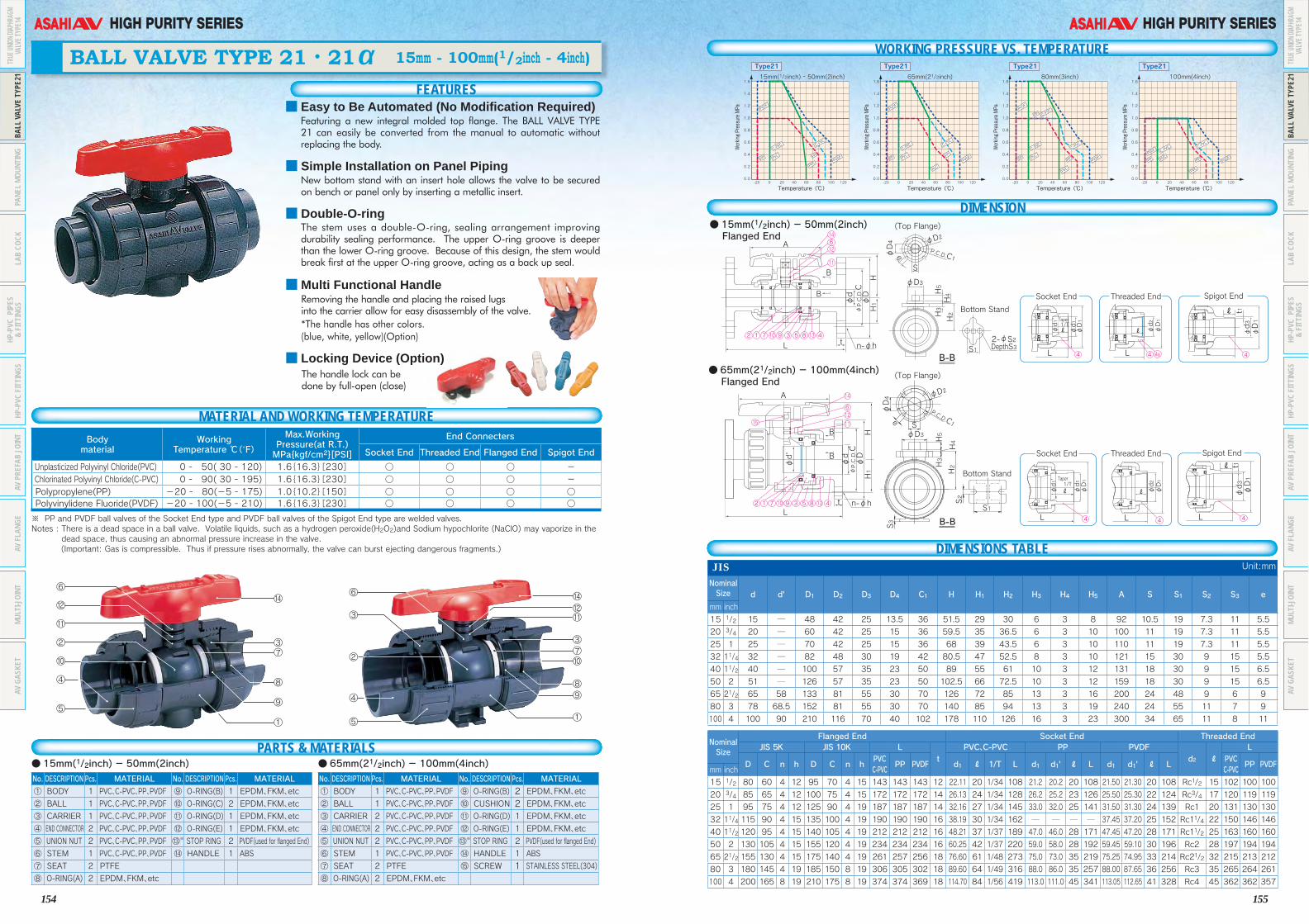
※ PP and PVDF ball valves of the Socket End type and PVDF ball valves of the Spigot End type are welded valves.Notes : There is a dead space in a ball valve. Volatile liquids, such as a hydrogen peroxide(H2O2)and Sodium hypochlorite (NaClO) may vaporize in the
dead space, thus causing an abnormal pressure increase in the valve. (Important: Gas is compressible. Thus if pressure rises abnormally, the valve can burst ejecting dangerous fragments.)
⑬※ See drawings on page 16 (only for flanged end type)
FEATURES
BALL VALVE TYPE 21・21α 15mm - 100mm(1/2inch - 4inch)
MATERIAL AND WORKING TEMPERATUREBody material
WorkingTemperature ℃(˚F)
Max.WorkingPressure(at R.T.)MPa{kgf/cm2}[PSI]
End Connecters
Socket End Threaded End Flanged End Spigot End
Unplasticized Polyvinyl Chloride(PVC) 0 - 50( 30 - 120) 1.6{16.3}[230] ○ ○ ○ - Chlorinated Polyvinyl Chloride(C-PVC) 0 - 90( 30 - 195) 1.6{16.3}[230] ○ ○ ○ - Polypropylene(PP) -20 - 80(-5 - 175) 1.0{10.2}[150] ○ ○ ○ ○ Polyvinylidene Fluoride(PVDF) -20 - 100(-5 - 210) 1.6{16.3}[230] ○ ○ ○ ○
No. DESCRIPTION Pcs. MATERIAL No. DESCRIPTION Pcs. MATERIAL
① BODY 1 PVC、C-PVC、PP、PVDF ⑨ O-RING(B) 1 EPDM、FKM、etc
② BALL 1 PVC、C-PVC、PP、PVDF ⑩ O-RING(C) 2 EPDM、FKM、etc
③ CARRIER 1 PVC、C-PVC、PP、PVDF ⑪ O-RING(D) 1 EPDM、FKM、etc
④ END CONNECTOR 2 PVC、C-PVC、PP、PVDF ⑫ O-RING(E) 1 EPDM、FKM、etc
⑤ UNION NUT 2 PVC、C-PVC、PP、PVDF ⑬※ STOP RING 2 PVDF(used for flanged End)
⑥ STEM 1 PVC、C-PVC、PP、PVDF ⑭ HANDLE 1 ABS
⑦ SEAT 2 PTFE
⑧ O-RING(A) 2 EPDM、FKM、etc
No. DESCRIPTION Pcs. MATERIAL No. DESCRIPTION Pcs. MATERIAL
① BODY 1 PVC、C-PVC、PP、PVDF ⑨ O-RING(B) 2 EPDM、FKM、etc② BALL 1 PVC、C-PVC、PP、PVDF ⑩ CUSHION 2 EPDM、FKM、etc③ CARRIER 2 PVC、C-PVC、PP、PVDF ⑪ O-RING(D) 1 EPDM、FKM、etc
④ END CONNECTOR 2 PVC、C-PVC、PP、PVDF ⑫ O-RING(E) 1 EPDM、FKM、etc
⑤ UNION NUT 2 PVC、C-PVC、PP、PVDF ⑬※ STOP RING 2 PVDF(used for flanged End)
⑥ STEM 1 PVC、C-PVC、PP、PVDF ⑭ HANDLE 1 ABS
⑦ SEAT 2 PTFE ⑮ SCREW 1 STAINLESS STEEL(304)⑧ O-RING(A) 2 EPDM、FKM、etc
●15mm(1/2inch) - 50mm(2inch) ● 65mm(21/2inch) - 100mm(4inch)
WORKING PRESSURE VS. TEMPERATURE
●15mm(1/2inch) - 50mm(2inch) Flanged End
● 65mm(21/2inch) - 100mm(4inch) Flanged End
DIMENSIONS TABLEJIS Unit:mm
Nominal Size d d' D1 D2 D3 D4 C1 H H1 H2 H3 H4 H5 A S S1 S2 S3 e
mm inch
15 1/2 15 ─ 48 42 25 13.5 36 51.5 29 30 6 3 8 92 10.5 19 7.3 11 5.5
20 3/4 20 ─ 60 42 25 15 36 59.5 35 36.5 6 3 10 100 11 19 7.3 11 5.5
25 1 25 ─ 70 42 25 15 36 68 39 43.5 6 3 10 110 11 19 7.3 11 5.5
32 11/4 32 ─ 82 48 30 19 42 80.5 47 52.5 8 3 10 121 15 30 9 15 5.5
40 11/2 40 ─ 100 57 35 23 50 89 55 61 10 3 12 131 18 30 9 15 6.5
50 2 51 ─ 126 57 35 23 50 102.5 66 72.5 10 3 12 159 18 30 9 15 6.5
65 21/2 65 58 133 81 55 30 70 126 72 85 13 3 16 200 24 48 9 6 9
80 3 78 68.5 152 81 55 30 70 140 85 94 13 3 19 240 24 55 11 7 9
100 4 100 90 210 116 70 40 102 178 110 126 16 3 23 300 34 65 11 8 11
Nominal Size
Flanged End Socket End Threaded EndJIS 5K JIS 10K L
tPVC、C-PVC PP PVDF
d2 ℓL
D C n h D C n hPVCC-PVC
PP PVDF d1 ℓ 1/T L d1 d1' ℓ L d1 d1' ℓ LPVCC-PVC
PP PVDFmm inch
15 1/2 80 60 4 12 95 70 4 15 143 143 143 12 22.11 20 1/34 108 21.2 20.2 20 108 21.50 21.30 20 108 Rc1/2 15 102 100 100
20 3/4 85 65 4 12 100 75 4 15 172 172 172 14 26.13 24 1/34 128 26.2 25.2 23 126 25.50 25.30 22 124 Rc3/4 17 120 119 119
25 1 95 75 4 12 125 90 4 19 187 187 187 14 32.16 27 1/34 145 33.0 32.0 25 141 31.50 31.30 24 139 Rc1 20 131 130 130
32 11/4 115 90 4 15 135 100 4 19 190 190 190 16 38.19 30 1/34 162 ─ ─ ─ ─ 37.45 37.20 25 152 Rc11/4 22 150 146 146
40 11/2 120 95 4 15 140 105 4 19 212 212 212 16 48.21 37 1/37 189 47.0 46.0 28 171 47.45 47.20 28 171 Rc11/2 25 163 160 160
50 2 130 105 4 15 155 120 4 19 234 234 234 16 60.25 42 1/37 220 59.0 58.0 28 192 59.45 59.10 30 196 Rc2 28 197 194 194
65 21/2 155 130 4 15 175 140 4 19 261 257 256 18 76.60 61 1/48 273 75.0 73.0 35 219 75.25 74.95 33 214 Rc21/2 32 215 213 212
80 3 180 145 4 19 185 150 8 19 306 305 302 18 89.60 64 1/49 316 88.0 86.0 35 257 88.00 87.65 36 256 Rc3 35 265 264 261
100 4 200 165 8 19 210 175 8 19 374 374 369 18 114.70 84 1/56 419 113.0 111.0 45 341 113.05 112.65 41 328 Rc4 45 362 362 357
A
BS
S12-φS2DepthS3
φd
φD
HH1
H4
φD1
φd3
φD1
φd1
φd1'
t1
LL
1/TTaper
ℓ
ℓ φD1
φd2
L
ℓ
φD1
φd3
φD1
φd1
φd1'
t1
LL
1/TTaper
ℓ
ℓ φD1
φd2
L
ℓ
H2
H5
H3
φD4
φD3
φD2
P.C.D.C1e
φP.C.D.C
B
B-B
B-B
L t n-φh
A
B
φd
φd'
φD
HH1φP.C.D.C
B
Lt n-φh
(Top Flange)
(Top Flange)
Bottom Stand
Bottom Stand
Socket End Spigot EndThreaded End
Socket End Spigot EndThreaded End
S1
S2
H2H3
H5
H4
S3
φD3S
φD4 φD2
P.C.D.C1e
614
4a
12
2 9 3 5 8 4
4 4 4
4 44
1 7 10 13
11
6
14
1512
2 9 3 5 8 41 7 10 13
11
1.0
1.2
1.4
1.6
0.6
0.8
0.2
0.4
0.012060 80 1000 20-20 40
Temperature(℃)
1.0
1.2
1.4
1.6
0.6
0.8
0.2
0.4
0.012060 80 1000 20-20 40
Temperature(℃)
1.0
1.2
1.4
1.6
0.6
0.8
0.2
0.4
0.012060 80 1000 20-20 40
Temperature(℃)
1.0
1.2
1.4
1.6
0.6
0.8
0.2
0.4
0.012060 80 1000 20-20 40
Temperature(℃)
PVDF
PVDF
PVDF
PVDF
PVDF
PVDF
PVDF
PVDFPP
PPPP
PPPP PP
PP
PP PP
C-PVC
C-PVC C-P
VC
C-PVC
C-PVC
C-PVC
C-PVC
C-PVC
C-PVC
PVC
PVC
PVC
PVC
PVC
PVC
PVC
PVC
15mm(1/2inch) - 50mm(2inch)
Type21
Working Pressure MPa
65mm(21/2inch)
Type21
Working Pressure MPa
80mm(3inch)
Type21
Working Pressure MPa
100mm(4inch)
Type21
Working Pressure MPa
DIMENSION
■ Easy to Be Automated (No Modification Required)Featuring a new integral molded top flange. The BALL VALVE TYPE 21 can easily be converted from the manual to automatic without replacing the body.
■ Simple Installation on Panel PipingNew bottom stand with an insert hole allows the valve to be secured on bench or panel only by inserting a metallic insert.
■ Double-O-ringThe stem uses a double-O-ring, sealing arrangement improving durability sealing performance. The upper O-ring groove is deeper than the lower O-ring groove. Because of this design, the stem would break first at the upper O-ring groove, acting as a back up seal.
■ Multi Functional HandleRemoving the handle and placing the raised lugsinto the carrier allow for easy disassembly of the valve.
*The handle has other colors.(blue, white, yellow)(Option)
■ Locking Device (Option)The handle lock can be done by full-open (close)
PARTS & MATERIALS
TRUE
UNION
DIAP
HRAG
MVA
LVE T
YPE1
4BA
LL V
ALVE
TYP
E21
PANE
L MO
UNTI
NGLA
B CO
CKHP
-PVC
PIP
ES&
FITT
INGS
HP-P
VC F
ITTI
NGS
AV P
REFA
B JO
INT
AV F
LANG
EMU
LTI-J
OINT
AV G
ASKE
T
TRUE
UNION
DIAP
HRAG
MVA
LVE T
YPE1
4BA
LL V
ALVE
TYP
E21
PANE
L MO
UNTI
NGLA
B CO
CKHP
-PVC
PIP
ES&
FITT
INGS
HP-P
VC F
ITTI
NGS
AV P
REFA
B JO
INT
AV F
LANG
EMU
LTI-J
OINT
AV G
ASKE
T
156
HIGH PURITY SERIES
157
HIGH PURITY SERIES
Note : Pay attention that the follwing chemicals such as Hydrgen Peroxide (H2O2)and Sodium hypochlorite (NaClO) are adapt to be occured the abnormal pressure rising due to their vaporization nature.
ANSI Unit:inch
Nominal Size d d' D1 D2 D3 D4 C1 H H1 H2 H3 H4 H5 A S S1 S2 S3 e
inch mm1/2 15 0.59 ─ 1.89 1.65 0.98 0.53 1.42 2.03 1.14 1.18 0.24 0.12 0.31 3.62 0.41 0.75 0.29 0.43 0.223/4 20 0.79 ─ 2.36 1.65 0.98 0.59 1.42 2.34 1.38 1.44 0.24 0.12 0.39 3.94 0.43 0.75 0.29 0.43 0.22
1 25 0.98 ─ 2.76 1.65 0.98 0.59 1.42 2.68 1.54 1.71 0.24 0.12 0.39 4.33 0.43 0.75 0.29 0.43 0.22
11/4 32 1.26 ─ 3.23 1.89 1.18 0.75 1.65 3.17 1.85 2.07 0.31 0.12 0.39 4.76 0.59 1.18 0.35 0.59 0.22
11/2 40 1.57 ─ 3.94 2.24 1.38 0.91 1.97 3.50 2.17 2.40 0.39 0.12 0.47 5.16 0.71 1.18 0.35 0.59 0.26
2 50 2.01 ─ 4.96 2.24 1.38 0.91 1.97 4.04 2.60 2.85 0.39 0.12 0.47 6.26 0.71 1.18 0.35 0.59 0.26
21/2 65 2.56 2.28 5.24 3.19 2.17 1.18 2.76 4.96 2.83 3.35 0.51 0.12 0.63 7.87 0.94 1.89 0.35 0.24 0.35
3 80 3.07 2.70 5.98 3.19 2.17 1.18 2.76 5.51 3.35 3.70 0.51 0.12 0.75 9.45 0.94 2.17 0.43 0.28 0.35
4 100 3.94 3.54 8.27 4.57 2.76 1.57 4.02 7.01 4.33 4.96 0.63 0.12 0.91 11.81 1.34 2.56 0.43 0.31 0.43
Nominal Size
Flanged End Socket End (IPS) Threaded End
ANSI CLASS 150 L
t
PVC, C-PVC PP, PVDF
d2 ℓ
L
D C n hPVC, C-PVC
PP PVDFASTM SCH40
LASTM SCH80
L d1 ℓL PVC,
C-PVCPP PVDF
inch mm d1 d1' ℓ d1 d1' ℓ PP PVDF1/2 15 3.50 2.38 4 0.62 5.63 5.63 5.63 0.47 ─ ─ ─ ─ 0.848 0.836 0.875 4.45 0.83 0.87 4.45 4.45 1/2-14 NPT 0.59 4.02 4.02 4.023/4 20 3.88 2.75 4 0.62 6.77 6.77 6.77 0.55 ─ ─ ─ ─ 1.058 1.046 1.000 5.08 1.03 1.00 5.08 5.08 3/4-14 NPT 0.67 4.72 4.72 4.72
1 25 4.25 3.12 4 0.62 7.36 7.36 7.36 0.55 ─ ─ ─ ─ 1.325 1.310 1.125 5.75 1.30 1.13 5.75 5.75 1-111/2NPT 0.79 5.16 5.16 5.16
11/4 32 4.62 3.50 4 0.62 7.48 7.48 7.48 0.63 ─ ─ ─ ─ 1.670 1.655 1.250 6.46 1.65 1.25 6.46 6.46 11/4-111/2NPT 0.87 5.91 5.91 5.91
11/2 40 5.00 3.88 4 0.62 8.35 8.35 8.35 0.63 ─ ─ ─ ─ 1.912 1.894 1.375 7.24 1.89 1.37 7.24 7.24 11/2-111/2NPT 0.98 6.42 6.42 6.42
2 50 6.00 4.75 4 0.75 9.21 9.21 9.21 0.63 ─ ─ ─ ─ 2.387 2.369 1.500 8.23 2.36 1.50 8.23 8.23 2-111/2NPT 1.10 7.76 7.76 7.76
21/2 65 7.00 5.50 4 0.75 10.20 10.12 10.08 0.71 ─ ─ ─ ─ 2.889 2.868 1.750 9.45 2.880 1.752 9.37 9.33 1/2-8 NPT 1.26 8.46 8.39 8.35
3 80 7.50 6.00 4 0.75 12.05 12.01 11.89 0.71 ─ ─ ─ ─ 3.516 3.492 1.875 11.14 3.480 1.874 11.10 10.98 3-8 NPT 1.38 10.43 10.39 10.28
4 100 9.00 7.50 8 0.75 14.72 14.72 14.53 0.71 4.518 4.491 2.000 13.86 ─ ─ ─ ─ 4.480 2.252 14.37 14.13 4-8 NPT 1.77 14.25 14.25 14.06
DIN Unit:mm
Nominal Size d d' D1 D2 D3 D4 C1 H H1 H2 H3 H4 H5 A S S1 S2 S3 e
mm inch
10 3/8 13 ─ 46 ─ ─ ─ ─ 43.5 ─ ─ ─ ─ ─ 80 ─ ─ ─ ─ ─
15 1/2 15 ─ 48 42 25 13.5 36 51.5 29 30 6 3 8 92 10.5 19 7.3 11 5.5
20 3/4 20 ─ 60 42 25 15 36 59.5 35 36.5 6 3 10 100 11 19 7.3 11 5.5
25 1 25 ─ 70 42 25 15 36 68 39 43.5 6 3 10 110 11 19 7.3 11 5.5
32 11/4 32 ─ 82 48 30 19 42 80.5 47 52.5 8 3 10 121 15 30 9 15 5.5
40 11/2 40 ─ 100 57 35 23 50 89 55 61 10 3 12 131 18 30 9 15 6.5
50 2 51 ─ 126 57 35 23 50 102.5 66 72.5 10 3 12 159 18 30 9 15 6.5
65 21/2 65 58 133 81 55 30 70 126 72 85 13 3 16 200 24 48 9 6 9
80 3 78 68.5 152 81 55 30 70 140 85 94 13 3 19 240 24 55 11 7 9
100 4 100 90 210 116 70 40 102 178 110 126 16 3 23 300 34 65 11 8 11
Nominal Size
Flanged End Socket End Threaded End Spigot EndDIN PN10
t
PVC、C-PVC PP、PVDF
d2 ℓ
L PVC PP、PVDFL
D C n hL
d1 ℓ L d1 d1' ℓL PVC
C-PVC PP PVDF d3 d3' ℓ d3 lt
mm inch PVCC-PVC PP PVDF PP PVDF PP PVDF PP PVDF
10 3/8 90 60 4 14 120 119 119 12 16 14 99 15.5 15.4 13 96 96 Rp3/8 15 99 98 98 16 13 16 ─ ─ ─ ─ 114 114
15 1/2 95 65 4 14 130 130 130 12 20 16 102 19.5 19.3 14.5 99 99 Rp1/2 15 102 100 100 20 15 18.5 20 18.5 2.5 1.9 124 124
20 3/4 105 75 4 14 150 150 150 14 25 19 120 24.5 24.3 16 113 113 Rp3/4 17 120 119 119 25 20 24 25 22 2.7 1.9 144 144
25 1 115 85 4 14 160 160 160 14 32 22 131 31.5 31.3 18 123 123 Rp1 20 131 130 130 32 25 24.5 32 22.5 3.0 2.4 154 154
32 11/4 140 100 4 18 180 180 180 16 40 26 150 39.45 39.2 20.5 139 139 Rp11/4 22 150 146 146 40 31 28 40 26 3.7 2.4 174 174
40 11/2 150 110 4 18 200200200 16 50 31 163 49.45 49.2 23.5149 149 Rp11/2 25 163 160 160 50 40 34 50 32 4.6 3.0 194 194
50 2 165 125 4 18 230230230 16 63 38 197 62.5 62.1 27.5 176 176 Rp2 28 197 194 194 63 51 38 63 36 5.8 3.0 224 224
65 21/2 185 145 4 18 290288287 18 75 44 233 74.25 73.95 31 205 204 Rp21/2 32 215 213 212 75 65 44 75 38 6.9 3.6 245 244
80 3 200 160 8 18 312 311 308 21 90 51 284 89.2 88.85 35.5252 249 Rp3 35 265 264 261 90 80 51 90 38 8.2 4.3 296 293
100 4 220 180 8 18 352 352347 18 110 61 351 109.05 108.65 41.5 312 307 Rp4 45 340 340335 110 93.6 46 110 44.5 10.0 5.3 355 350
Note : The shape and appearance of the valve differ a little with nominal size compared to the drawing.
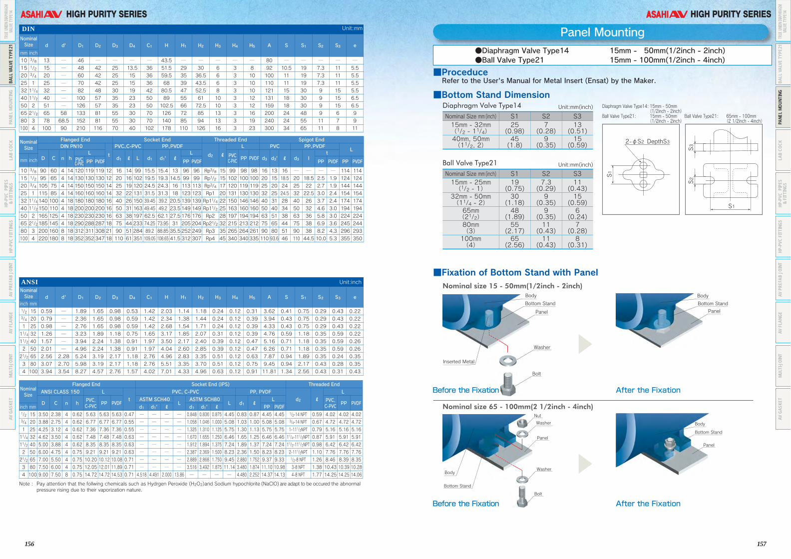
Panel Mounting
Nominal Size mm(inch) S1 S2 S315mm - 32mm(1/2 - 11/4)
25(0.98)
7(0.28)
13(0.51)
40mm, 50mm(11/2, 2)
45(1.8)
9(0.35)
15(0.59)
■Fixation of Bottom Stand with PanelNominal size 15 - 50mm(1/2inch - 2inch)
Washer
Bolt
Panel
Bottom Stand
Body
Inserted Metal
Panel
Bottom Stand
Body
Bolt
Washer
Panel
Washer
Nut
Bottom Stand
Body
Panel
Bottom Stand
Body
Before the Fixation
●Diaphragm Valve Type14 15mm - 050mm(1/2inch - 2inch)●Ball Valve Type21 15mm - 100mm(1/2inch - 4inch)
Before the Fixation
After the Fixation
After the Fixation
Nominal size 65 - 100mm(2 1/2inch - 4inch)
▲▲
■Proceduce Refer to the User's Manual for Metal Insert (Ensat) by the Maker.
■Bottom Stand DimensionDiaphragm Valve Type14
Nominal Size mm(inch) S1 S2 S315mm - 25mm(1/2 - 1)
19(0.75)
7.3(0.29)
11(0.43)
32mm - 50mm(11/4 - 2)
30(1.18)
9(0.35)
15(0.59)
65mm(21/2)
48(1.89)
9(0.35)
6(0.24)
80mm(3)
55(2.17)
11(0.43)
7(0.28)
100mm(4)
65(2.56)
11(0.43)
8(0.31)
Ball Valve Type21
Unit:mm(inch)
Unit:mm(inch)
S1
S2
2-φS2 DepthS3
S3
S1
Diaphragm Valve Type14: 15mm - 50mm (1/2inch - 2inch)Ball Valve Type21: 15mm - 50mm (1/2inch - 2inch)
Ball Valve Type21: 65mm - 100mm (2 1/2inch - 4inch)
TRUE
UNION
DIAP
HRAG
MVA
LVE T
YPE1
4BA
LL V
ALVE
TYP
E21
PANE
L MO
UNTI
NGLA
B CO
CKHP
-PVC
PIP
ES&
FITT
INGS
HP-P
VC F
ITTI
NGS
AV P
REFA
B JO
INT
AV F
LANG
EMU
LTI-J
OINT
AV G
ASKE
T
TRUE
UNION
DIAP
HRAG
MVA
LVE T
YPE1
4BA
LL V
ALVE
TYP
E21
PANE
L MO
UNTI
NGLA
B CO
CKHP
-PVC
PIP
ES&
FITT
INGS
HP-P
VC F
ITTI
NGS
AV P
REFA
B JO
INT
AV F
LANG
EMU
LTI-J
OINT
AV G
ASKE
T
158
HIGH PURITY SERIES
159
HIGH PURITY SERIES
15
φ23
32
35
φ16
φ6
R1/2
35.5 57.5
93
41
7
4
6
3b 3c1 2 5 8
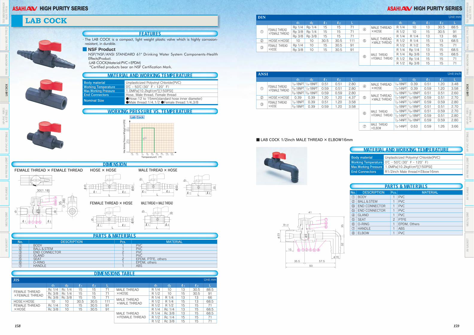
■ LAB COCK 1/2inch MALE THREAD× ELBOW16mm
Body material Unplasticized Polyvinyl Chloride(PVC)
Working Temperature 0℃ - 50℃(30゜F - 120゜F) Max.Working Pressure 1.0MPa{10.2kgf/cm2}[150PSI]
End Connectors R1/2inch Male thread×Elbow16mm
MATERIAL AND WORKING TEMPERATURE
PARTS & MATERIALSNo. DESCRIPTION Pcs. MATERIAL① BODY 1 PVC② BALL&STEM 1 PVC3b END CONNECTOR 1 PVC3c END CONNECTOR 1 PVC④ GLAND 1 PVC⑤ SEAT 2 PTFE⑥ O-RING 1 EPDM, Others⑦ HANDLE 1 ABS⑧ ELBOW 1 PVC
DIN Unit:mm
d1 d2 ℓ1 ℓ2 L d1 d2 ℓ1 ℓ2 L
① FEMALE THREAD ×FEMALE THREAD
Rp 1/4 Rp 1/4 15 15 71④ MALE THREAD
×HOSER 1/4 10 13 30.5 88.5
Rp 3/8 Rp 1/4 15 15 71 R 1/2 10 15 30.5 91Rp 3/8 Rp 3/8 15 15 71
⑤ MALE THREAD ×MALE THREAD
R 1/4 R 1/4 13 13 66② HOSE×HOSE 10 10 30.5 30.5 111 R 1/2 R 1/4 15 13 68.5
③ FEMALE THREAD ×HOSE
Rp 1/4 10 15 30.5 91 R 1/2 R 1/2 15 15 71Rp 3/8 10 15 30.5 91
⑥ MALE THREAD ×FEMALE THREAD
R 1/4 Rp 1/4 13 15 68.5R 1/4 Rp 3/8 13 15 68.5R 1/2 Rp 1/4 15 15 71R 1/2 Rp 3/8 15 15 71
ANSI Unit:inch
d1 d2 ℓ1 ℓ2 L d1 d2 ℓ1 ℓ2 L
① FEMALE THREAD ×FEMALE THREAD
1/4-18NPT 1/4-18NPT 0.51 0.51 2.80④ MALE THREAD
×HOSE
1/4-18NPT 0.39 0.51 1.20 3.483/8-18NPT 1/4-18NPT 0.59 0.51 2.80 1/2-14NPT 0.39 0.59 1.20 3.583/8-18NPT 3/8-18NPT 0.59 0.59 2.80
⑤ MALE THREAD ×MALE THREAD
1/4-18NPT 1/4-18NPT 0.51 0.51 2.60② HOSE×HOSE 0.39 0.39 1.20 1.20 4.37 1/2-14NPT 1/4-18NPT 0.59 0.51 2.70
③ FEMALE THREAD ×HOSE
1/4-18NPT 0.39 0.51 1.20 3.58 1/2-14NPT 1/2-14NPT 0.59 0.59 2.803/8-18NPT 0.39 0.59 1.20 3.58
⑥ MALE THREAD ×FEMALE THREAD
1/4-18NPT 1/4-18NPT 0.51 0.51 2.701/4-18NPT 3/8-18NPT 0.51 0.59 2.701/2-14NPT 1/4-18NPT 0.59 0.51 2.801/2-14NPT 3/8-18NPT 0.59 0.59 2.80
⑦ MALE THREAD ×ELBOW
1/2-14NPT 0.63 0.59 1.26 3.66
FEATURES
LAB COCK
MATERIAL AND WORKING TEMPERATURE
WORKING PRESSURE VS. TEMPERATURE
DIMENSION
DIMENSIONS TABLE
35
L
L L
L
L
L
ℓ1
ℓ1 ℓ1
ℓ1 ℓ2
ℓ1 ℓ2ℓ2ℓ2
ℓ1 ℓ2ℓ2
d1
φd1
d1
d1
d1
d1
d2
φd2
φd2
φd2
d2
d2φ6
φ6
30(1.18)
(1.38)7
46
3 1 2 5
FEMALE THREAD× FEMALE THREAD HOSE× HOSE
FEMALE THREAD× HOSE
MALE THREAD× HOSE
MALE THREAD×MALE THREAD
・ The LAB COCK is a compact, light weight plastic valve which is highly corrosion-resistant, in durable.
Body material Unplasticized Polyvinyl Chloride(PVC) Working Temperature 0℃ - 50℃(30゜F - 120゜F) Max.Working Pressure 1.0MPa{10.2kgf/cm2}[150PSI] End Connectors Hose, Male thread, Female thread
Nominal Size ●Hose:12 to 15mm(standard hose inner diameter) ●Male thread:1/4,1/2 ●Female thread:1/4,3/8
No. DESCRIPTION Pcs. MATERIAL① BODY 1 PVC② BALL&STEM 1 PVC③ END CONNECTOR 2 PVC④ GLAND 1 PVC⑤ SEAT 2 EPDM, PTFE, others⑥ O-RING 1 EPDM, others⑦ HANDLE 1 ABS
JIS Unit:mm
d1 d2 ℓ1 ℓ2 L d1 d2 ℓ1 ℓ2 L
FEMALE THREAD ×FEMALE THREAD
Rc 1/4 Rc 1/4 15 15 71 MALE THREAD ×HOSE
R 1/4 10 13 30.5 88.5Rc 3/8 Rc 1/4 15 15 71 R 1/2 10 15 30.5 91Rc 3/8 Rc 3/8 15 15 71
MALE THREAD ×MALE THREAD
R 1/4 R 1/4 13 13 66 HOSE×HOSE 10 10 30.5 30.5 111 R 1/2 R 1/4 15 13 68.5 FEMALE THREAD ×HOSE
Rc 1/4 10 15 30.5 91 R 1/2 R 1/2 15 15 71Rc 3/8 10 15 30.5 91
MALE THREAD ×FEMALE THREAD
R 1/4 Rc 1/4 13 15 68.5R 1/4 Rc 3/8 13 15 68.5R 1/2 Rc 1/4 15 15 71R 1/2 Rc 3/8 15 15 71
■ NSF ProductNSF("NSF/ANSI STANDARD 61" Drinking Water System Components-Health Effects)Product.:LAB COCK(Material:PVC+EPDM) *Certified products bear an NSF Certification Mark.
{10.2}1.0
0.5
0.0
{5.1}
12060 80 100
[150]
[70]
0 20-40 -20 40(250)(140) (175) (210)(30) (90)(-40) (-5) (105)
Temperature℃( F゚)
PVC
Max Working Pressure MPa{kgf/cm2 }[PSI]
Lab Cock
PARTS & MATERIALS
TRUE
UNION
DIAP
HRAG
MVA
LVE T
YPE1
4BA
LL V
ALVE
TYP
E21
PANE
L MO
UNTI
NGLA
B CO
CKHP
-PVC
PIP
ES&
FITT
INGS
HP-P
VC F
ITTI
NGS
AV P
REFA
B JO
INT
AV F
LANG
EMU
LTI-J
OINT
AV G
ASKE
T
TRUE
UNION
DIAP
HRAG
MVA
LVE T
YPE1
4BA
LL V
ALVE
TYP
E21
PANE
L MO
UNTI
NGLA
B CO
CKHP
-PVC
PIP
ES&
FITT
INGS
HP-P
VC F
ITTI
NGS
AV P
REFA
B JO
INT
AV F
LANG
EMU
LTI-J
OINT
AV G
ASKE
T

160
HIGH PURITY SERIES
161
HIGH PURITY SERIES
HP-PVC PIPE & FITTINGS HP-PVC PIPE & FITTINGS
●Elbow(L) Unit:mm
Nominal Size (mm) D t H
13 24 3.0 3616 29 3.5 4320 33 3.5 5025 40 4.0 5830 46 4.0 6540 57 4.5 8250 70 5.0 96
※ 65 87 6.6 110※ 75 102 8.0 120※ 100 130 10.0 153※ 125 157 11.0 188※ 150 186 13.0 230
□ 200 240 15.0 265□ 250 295 16.0 310
300 347 18.0 350(Note)1.The tolerances on H are +5/-1mm.2.The Nominal Size marked with ※ conform to the JPPFA standard.3.The Nominal Size marked with □ conform to the AV standard.
●HP-PVC Pipe <CLASS VP:JIS K6741> Unit:mm
Nominal Size(mm)
D t d LOuter diameter Wall Thickness
ApproximateI.D.
(for reference)LengthBasic
Dimension(mm)
Maximum and Minimumtolerances
Averagetolerances Minimum Tolerance
13 18 ±0.2 ±0.2 2.2 +0.6 13 4,000±1016 22 ±0.2 ±0.2 2.7 +0.6 16 4,000±1020 26 ±0.2 ±0.2 2.7 +0.6 20 4,000±1025 32 ±0.2 ±0.2 3.1 +0.8 25 4,000±1030 38 ±0.3 ±0.2 3.1 +0.8 31 4,000±1040 48 ±0.3 ±0.2 3.0 +0.8 40 4,000±1050 60 ±0.4 ±0.2 4.1 +0.8 51 4,000±1065 76 ±0.5 ±0.3 4.1 +0.8 67 4,000±1075 89 ±0.5 ±0.3 5.5 +0.8 77 4,000±10100 114 ±0.6 ±0.4 6.6 +1.0 100 4,000±10125 140 ±0.8 ±0.5 7.0 +1.0 125 4,000±10150 165 ±1.0 ±0.5 8.9 +1.4 146 4,000±10200 216 ±1.3 ±0.7 10.3 +1.4 194 4,000±10250 267 ±1.6 ±0.9 12.7 +1.8 240 4,000±10300 318 ±1.9 ±1.0 15.1 ±2.2 286 4,000±10
(Note)1.The tolerances of lengths are ± 10mm.2. The maximum and minimum tolerances on outside diameters are the tolerances on O.D. measurements taken at randomly selected spots.
3. The average tolerances on outside diameters are the tolerances on the arithmetical mean of O.D. measurements taken at randomly selected spots in two directions at a right angle to each other.
HP-PVC Pipe <CLASS VP:JIS K6741>
●Dimensions Commom All of AV TS Socket. JIS K6743 Unit:mmNominal Size(mm)
d1Toleranceon d1
d2 ℓ 1/T D DTToleranceon
D&DT
d(minimumvalue)
Pipe O.D.
13 18.40 ±0.20 - 26 1/30 24 24.0 -0.6 13 1816 22.40 ±0.20 - 30 1/34 29 29.0 -0.7 16 2220 26.45 ±0.20 - 35 1/34 33 33.0 -0.8 20 2625 32.55 ±0.25 - 40 1/34 40 40.0 -1.0 25 3230 38.60 ±0.25 - 44 1/34 46 46.0 -1.0 31 3840 48.70 ±0.30 - 55 1/37 57 57.0 -1.2 40 4850 60.80 ±0.30 - 63 1/37 70 70.0 -1.5 51 60
※ 65 76.60 ±0.30 - 61 1/48 87 88.5 -1.5 67 7675 89.60 ±0.30 - 64 1/49 102 104.5 -1.5 77 89100 114.70 ±0.30 - 84 1/56 130 133.5 -1.8 100 114※125 140.85 ±0.35 - 104 1/58 157 161.0 -1.8 125 140150 166.00 ±0.40 - 132 1/63 186 190.0 -2.0 146 165※200 217.00 - 214.10 145 - 240 - - 194 216※250 268.20 - 265.00 155 - 295 - - 247 267※300 319.6 - 315.50 175 - 347 - - 298 318(Note)1.The tolerances on l are +4/-0.5mm.2.The Nominal Size marked with ※ conform to the AV standard and the JPPFA standard.
Fittings in size 200, 250mm are available on request by FRP reinforcement. Max working pressure 200mm : 1.0MPa{10.2kgf/cm2} at 20℃ 250mm : 1.0MPa{10.2kgf/cm2} at 20℃
ℓ ℓ
Taper 1/T φd1
φd
φD
φd1φD
φDT
φd2
φd
H
D
H
t
H
H
D
t
▼13mm - 50mm
▼65mm - 300mm
t
L
φd
φD
▼13mm - 150mm ▼200mm - 300mm
Working Pressure with Temperature
Temp.Nom. Size 20℃ 30℃ 40℃ 50℃
13mm - 300mm 1.0{10.2}0.9{9.2} 0.7{7.1} 0.3{3.1}
MPa{kgf/cm2}
Note:This data is applicable for ultrapure water.
Working Pressure with Temperature
Temp.Nom. Size 20℃ 30℃ 40℃ 50℃
13mm - 150mm 1.0{10.2}0.9{9.2} 0.7{7.1} 0.3 {3.1}200mm 0.75{7.7}0.6{6.1} 0.5{5.1}0.25{2.6}250mm 0.6{6.1} 0.5{5.1} 0.4{4.1} 0.2{2.0}
300mm Elbow, Reducing Socket, Socket 0.6{6.1} 0.5{5.1} 0.4{4.1} 0.2{2.1}300mm Other Fitting 0.4{4.1} 0.4{4.1} 0.3{3.1} 0.1{1.1}
MPa{kgf/cm2}
Note:This data is applicable for ultrapure water.
Dimensions Common All of AV TS Socket. JIS K6743
Elbow(L)
●90゜AV Bend Unit:mm
Nominal Size(mm) D t H
□ 200 240 15 341
□ 250 293 16 402
300 337 10 395(Note)1.The Nominal Size marked with □ conform to the AV standard.
●45゜Elbow(45L) Unit:mm
Nominal Size(mm) D t H
20 33 3.5 44
25 40 4.0 51
●45゜AV Bend Unit:mm
Nominal Size(mm) D t H
40 57 4.5 69
50 70 5.0 80
65 87 6.0 81
□ 75 101 6.6 97
□ 100 129 7.3 122
□ 125 156 7.7 149
□ 150 185 10.0 184
□ 200 240 15.0 193
□ 250 293 16.0 213
300 337 10.0 225(Note)1.The Nominal Size marked with □ conform to the AV standard.
t
HφD
H
D
t
H
45°
H
H
t
φD
90˚ AV Bend
45˚ Elbow(45L)
45˚ AV Bend
TRUE
UNION
DIAP
HRAG
MVA
LVE T
YPE1
4BA
LL V
ALVE
TYP
E21
PANE
L MO
UNTI
NGLA
B CO
CKHP
-PVC
PIP
ES&
FITT
INGS
HP-P
VC F
ITTI
NGS
AV P
REFA
B JO
INT
AV F
LANG
EMU
LTI-J
OINT
AV G
ASKE
T
TRUE
UNION
DIAP
HRAG
MVA
LVE T
YPE1
4BA
LL V
ALVE
TYP
E21
PANE
L MO
UNTI
NGLA
B CO
CKHP
-PVC
PIP
ES&
FITT
INGS
HP-P
VC F
ITTI
NGS
AV P
REFA
B JO
INT
AV F
LANG
EMU
LTI-J
OINT
AV G
ASKE
T

162
HIGH PURITY SERIES
163
HIGH PURITY SERIES
●Socket(S) Unit:mm
Nominal Size (mm) D L
13 24 57
16 29 67
20 33 77
25 40 87
30 46 95
40 57 117
50 70 133
※ 65 87 145
75 102 155
100 130 200
※ 125 157 240
150 186 300
□ 200 238 305
□ 250 295 352
300 336 360(Note)1.The tolerances on L are ±4mm.2.The Nominal Size marked with ※ conform to the JPPFA standard.3.The Nominal Size marked with □ conform to the AV standard.
●Reducing Socket(RS) Unit:mm
Nominal Size (mm) D D1 L
20×13 33 24 68
20×16 33 29 71
25×13 40 24 86
25×16 40 29 85
25×20 40 33 84
○ 30×13 48.2 28.2 73.2
○ 30×20 48.2 36.2 83
30×25 46 40 93
※ 40×20 57 33 113
40×25 57 40 114
40×30 57 46 114
※ 50×20 70 33 116
※ 50×25 70 40 140
50×40 70 57 136
※ 65×50 87 70 149
75×50 102 70 165
※ 75×65 102 87 159
100×75 130 102 190
※ 125×100 157 130 229
※ 150×125 186 157 272
□ 200×150 240 188 356
□ 250×200 293 240 380
300×250 347 295 405(Note)1.The tolerances on L are ±4.0mm.2.The Nominal Size marked with ※ conform to the JPPFA standard.3.The Nominal Size marked with □ conform to the AV standard.4.○ There sizes are not in accordance with JISK 6743 and therefore welding arrangement is not available.
L
DD
L
▼13mm~50mm
▼65mm~300mm
D D1
L
D 1D
L
▼13mm - 50mm
▼65mm - 300mm
HP-PVC FITTINGS HP-PVC FITTINGSSocket(S) Tee(T)
Reducing Socket(RS)
●Tee(T) Unit:mm
Nominal Size (mm) D t H H1
13 24 3.0 36 36
16 29 3.5 43 43
20 33 3.5 50 50
25 40 4.0 58 58
30 46 4.0 65 65
40 57 4.5 82 82
50 70 5.0 96 96
※ 65 87 6.6 110 110
75 102 8.0 120 120
100 130 10.0 152 152
※ 125 157 11.0 187 187
150 186 13.0 230 230
□ 200 240 15.0 266 266
□ 250 295 16.0 331 331
300 337 10.0 340 340(Note)1.The tolerances on H are +5/-1mm.2.The Nominal Size marked with ※ conform to the JPPFA standard.3.The Nominal Size marked with □ conform to the AV standard.
●Reducing Tee(RT) Unit:mm
Nominal Size (mm) D t H D1 H1
16× 13 29 3.5 41 24 38
20× 13 33 3.5 46 24 40
20× 16 33 3.5 48 29 45
25× 13 40 4.0 51 24 43
25× 16 40 4.0 53 29 48
25× 20 40 4.0 55 33 53
○30× 13 48.2 6.5 54.7 28.2 44
30× 16 46 4.0 57 29 51
30× 20 46 4.0 59 33 56
30× 25 46 4.0 62 40 61
40× 13 57 4.5 66 24 52
○40× 16 58.4 5.2 62.4 30.9 52.5
40× 20 57 4.5 70 33 62
40× 25 57 4.5 73 40 67
40× 30 57 4.5 76 46 71
50× 13 70 5.0 74 24 58
50× 16 70 5.0 76 29 63
50× 20 70 5.0 78 33 68
50× 25 70 5.0 81 40 73
50× 30 70 5.0 84 46 77
50× 40 70 5.0 90 57 88
※ 65× 40 87 6.6 100 57 95
※ 65× 50 87 6.6 101 70 104
75× 25 102 8.0 93 40 88
75× 40 102 8.0 100 57 102
75× 50 102 8.0 105 70 110
100× 50 130 10.0 125 75 122
100× 75 130 10.0 140 102 132
※ 125× 75 157 11.0 160 102 147
※ 125×100 157 11.0 173 130 167
150× 75 186 13.0 195 102 158
150×100 186 13.0 208 130 182
※ 150×125 186 13.0 217 157 201
□ 200× 75 240 15.0 201 102 180
□ 200×100 240 15.0 215 130 200
□ 200×150 240 15.0 238 188 253
□ 250× 75 295 16.0 226 108 210
□ 250×100 295 16.0 246 136 225
□ 250×200 295 16.0 304 245 310
□ 300× 75 343 17.0 361 102 236
▼13mm - 50mm
D
1H
D
H H
t
▼65mm - 300mm
D
H
t
H1
D
H
▼13mm - 50mm
1D
1H
D
H H
t
▼65mm - 300mm
D
H
t
H1
D1
H
Reducing Tee(RT)
(Note)1.The tolerances on H are +5/-1mm.2.The Nominal Size marked with ※ conform to the JPPFA standard.3.The Nominal Size marked with □ conform to the AV standard.4.○ There sizes are not in accordance with JISK 6743 and therefore welding arrangement is not available.
TRUE
UNION
DIAP
HRAG
MVA
LVE T
YPE1
4BA
LL V
ALVE
TYP
E21
PANE
L MO
UNTI
NGLA
B CO
CKHP
-PVC
PIP
ES&
FITT
INGS
HP-P
VC F
ITTI
NGS
AV P
REFA
B JO
INT
AV F
LANG
EMU
LTI-J
OINT
AV G
ASKE
T
TRUE
UNION
DIAP
HRAG
MVA
LVE T
YPE1
4BA
LL V
ALVE
TYP
E21
PANE
L MO
UNTI
NGLA
B CO
CKHP
-PVC
PIP
ES&
FITT
INGS
HP-P
VC F
ITTI
NGS
AV P
REFA
B JO
INT
AV F
LANG
EMU
LTI-J
OINT
AV G
ASKE
T

164
HIGH PURITY SERIES
165
HIGH PURITY SERIES
●Faucet Elbow(FL) Unit:mm
Nominal Size (mm) D t D1 D2 ℓ1 ℓ2 T H
H1 Nominal size of female threadsS形
□ 13 24 3.0 30 34 17 14 4 38 29 Rp1/2□ 16 29 3.5 30 34 17 14 4 43 32 Rp1/2□ 20 33 3.5 37 42 19 16 4 51 36 Rp3/4□ 25 40 4.0 46 52 21 18 5 59 40 Rp1
(Note)1. The threaded portions employ parallel female threads specified in JIS B 0203(Taper Pipe Threads).
2.The tolerances on H are +5/-2mm.3.The tolerances on H1 are +5/-2mm.4.The Nominal Size marked with □ conform to the AV standard.5.The tolerances on ℓ2 are ±1mm.
●Valve Socket(VS) Unit:mm
Nominal Size (mm) D d
O.D. of basic form D1
Number of threads per inch
Location of basic diameterℓ1
ℓ2(Minimun)
T L B
13×1/2 24 13 20.955 14 8.16 13.16 6 50 24
16×1/2 29 13 20.955 14 8.20 15 6 54 29
20×3/4 33 18 26.441 14 9.53 14.53 8 64 33
25×1 40 23 33.249 11 10.39 16.79 8 71 40
30×11/4 46 31 41.910 11 12.70 19.10 10 80 46
40×11/2 57 37 47.803 11 12.70 19.10 10 92 57
50×2 70 48 59.614 11 15.88 23.38 12 106 70
□ 65×21/2 87 62 75.184 11 17.46 26 14 118 87
□ 75×3 102 72 87.884 11 20.64 30 16 128 102
□ 100×4 130 96 113.030 11 25.40 36 18 157 130(Note)1. The threaded portions employ parallel female threads specified in JIS B 0203(Taper Pipe Threads).
2.The tolerances on L are +5/-2mm.3.The Nominal Size marked with ※ conform to the JPPFA standard.4.The Nominal Size marked with □ conform to the AV standard.
●Faucet Socket(FS) Unit:mm
Nominal Size (mm) D D1 D2 ℓ1 ℓ2 T L
Nominal size of female threads
□ 13 24 30 34 17 14 4 47 Rp1/2□ 16 29 30 34 17 24 4 52 Rp1/2□ 20 33 37 42 19 16 4 59 Rp3/4□ 25 40 46 52 21 18 5 68 Rp1
(Note)1. The threaded portions employ parallel female threads specified in JIS B 0203(Taper Pipe Threads).
2.The tolerances on L are +5/-1mm.3.The tolerances on ℓ2 are ±1mm.4.The Nominal Size marked with □ conform to the AV standard.
●Cap(C) Unit:mm
Nominal Size (mm) D t L
13 24 3.0 29.0
16 29 3.5 33.5
20 33 3.5 38.5
25 40 4.0 44.0
40 57 4.5 59.5
50 70 5.0 68.0
※ 65 87 6.6 96.0
75 102 8.0 105.0
100 130 10.0 138.0 (Note)1.The tolerances on L are +5/-20mm.2.The Nominal Size marked with ※ conform to the JPPFA standard.3.R is 1 to 5mm
Precautions in use・when connecting threaded portions, use both sealing tape and gaskets jointly.・Do not use HP-PVC Faucet Elbows to connect steel pipes and PVC pipes.・Secure the elbows with fixtures.
ℓℓ12
1H
H
φD
φD1
φD2
T
t
T
L
φD1
φD φd
Bℓ2ℓ1
L
T
φD
φD1
φD2
ℓ1ℓ2
L
D
t
R
L
t
D
R
▼13mm - 50mm
▼65mm - 100mm
HP-PVC FITTINGS AV PREFAB JOINT <UNION>Faucet Elbow(FL)
AV TS FLANGE(JIS 10K 13mm - 300mm)
Valve Socket(VS)
Precautions in use・Do not repeat screw-in and removal.・when connecting threaded portions, use sealing tape.
Faucet Socket(FS)
Precautions in use・when connecting threaded portions, use both sealing tape and gaskets jointly.・Do not use HP-PVC Faucet Elbows to connect steel pipes and PVC pipes.・Secure the elbows with fixtures.
Cap(C)
AV FLANGE <HP-PVC>AV Q FLANGE(JIS 10K 15mm - 150mm)
Unit:mm
Nominal Size d
Socket End Threaded EndDU‐PVC、C‐PVC U‐PVC
mm inch d1 ℓ 1/T L d1 ℓ L13 3/8 13 18.13 18 1/34 46.0 RC3/8 15 43 48
16 1/2 15 22.11 20 1/34 46.0 Rc1/2 15 43 48
20 3/4 20 26.13 24 1/34 61.0 RC3/4 17 57 60
25 1 25 32.16 27 1/34 70.0 Rc1 20 63 70
30 11/4 31 38.19 30 1/34 77.0 Rc11/4 22 71 82
40 11/2 40 48.21 37 1/37 95.0 Rc11/2 25 82 100
50 2 51 60.25 42 1/37 107.0 Rc2 28 96 106
65 21/2 65 76.60 61 1/48 164.0 ― ― ― 133
75 3 77 89.60 64 1/49 189.5 ― ― ― 152
100 4 100 114.70 84 1/56 245.0 ― ― ― 210
Unit:mm
Nominal Size d
JIS 10Kd1 Taper
1/T D1 t T ℓ+4.0-0.5 L
mm inch D C n h13 3/8 15 90 65 4 15 18.40±0.20 1/30 25.5 14 - 26 30.0 15 1/2 18 95 70 4 15 22.40±0.20 1/34 31.0 14 12 30 35.0 20 3/4 22 100 75 4 15 26.45±0.20 1/34 35.0 15 14 35 40.0 25 1 25 125 90 4 19 32.55±0.25 1/34 42.5 15 14 40 46.0 32 11/4 30 135 100 4 19 38.60±0.25 1/34 48.5 16 16 44 50.5 40 11/2 41 140 105 4 19 48.70±0.30 1/37 60.5 16 16 55 61.5 50 2 52 155 120 4 19 60.80±0.30 1/37 73.0 20 16 63 71.0 65 21/2 67 175 140 4 19 76.60±0.30 1/48 90.0 22 18 61 70.0
80(75) 3 78 185 150 8 19 89.60±0.30 1/49 105.0 22 18 64 73.0 100 4 100 210 175 8 19 114.70±0.30 1/56 131.0 22 18 84 93.0 125 5 125 250 210 8 23 140.85±0.35 1/58 158.0 24 20 104 114.0 150 6 146 280 240 8 23 166.00±0.40 1/63 185.0 26 22 132 142.0 200 8 196 330 290 12 23 217.00±1.00 1/50 238.0 28 - 145 156.0 250 10 247 400 355 12 25 268.00±1.50 1/55 300.0 30 - 155 167.0 300 12 298 445 400 16 25 318.70±1.80 1/55 341.0 30 - 155 167.0 (Note)1.For detaols of AV Flanges, refer to the individual catalogs of appropriate AV Flanges.2.Products compliant with the clean water standard or ANSI standard are also avaliable.
(Note)For pressure limits by working temperature ranges and materials, see "WORKING PRESSURE VS. TEMPERATURE" in this catalog.
※ The figure described by broken (dashed) line shows shape of Q-flange applied for dead end service of piping.
2 3 4 12 3 4 1Socket End Threaded End
L
φD
φD
L
φd φd1
φd2
ℓ ℓ ℓ ℓ
φdφd1
φd2
Taper1/T
Taper1/T
φD1
P.C.D.Cn~φh
φD
φd
φd1
L ℓ
TaperT1
t
P.C.D.CφD
T
n~φh
SPECIFICATIONSMaterial Working
temperatureWorking pressureMPa{kgf/cm2}
Nominal Size (mm) Connection
Unplasticized Polyvinyl Chloride (U-PVC)
O℃~50℃ 1.0{10.2}13~100 Socket End
13~50 Threaded End
Chlorinated Polyvinyl Chloride (C-PVC)
O℃~90℃ 1.0{10.2} 13~100 Socket End
No. DESCRIPTION Pcs. MATERIAL① BODY 1 U-PVC, C‐PVC② END CONNECTOR 1 U-PVC, C‐PVC③ UNION NUT 1 U-PVC, C‐PVC④ O-RING 1 EPDM, FKM, others
PARTS & MATERIALS
TRUE
UNION
DIAP
HRAG
MVA
LVE T
YPE1
4BA
LL V
ALVE
TYP
E21
PANE
L MO
UNTI
NGLA
B CO
CKHP
-PVC
PIP
ES&
FITT
INGS
HP-P
VC F
ITTI
NGS
AV P
REFA
B JO
INT
AV F
LANG
EMU
LTI-J
OINT
AV G
ASKE
T
TRUE
UNION
DIAP
HRAG
MVA
LVE T
YPE1
4BA
LL V
ALVE
TYP
E21
PANE
L MO
UNTI
NGLA
B CO
CKHP
-PVC
PIP
ES&
FITT
INGS
HP-P
VC F
ITTI
NGS
AV P
REFA
B JO
INT
AV F
LANG
EMU
LTI-J
OINT
AV G
ASKE
T

166
HIGH PURITY SERIES
167
HIGH PURITY SERIES
■ High Safety Factor By A Molding(Multi-Joint Type "L" with Female connection 40mm - 150mm) They are produced by "Injection molding" which provides customers with complete reliability and durability.
■ SpecificationsTypes : Type "L", Type"T"Sizes : 20mm - 200mm (JIS standard)Connection : Both types are classified by female and socket connection respectively, which enable users to have multiple selections in connection with sensors, sampling valves, etc.
■ Designed By CAE AnalysisMulti-Joint is designed in a way to optimize many factors relating to piping stress by "CAE Hydromechanical Analysis".
MULTI-JOINTFEATURES
SPECIFICATIONS Body material High purity polyvinyl chloride
End Connectors Threaded, Socket Nominal Size 20mm - 200mm Working Temperature 50℃
Max. Working Pressure 1.0MPa
■ High PerformanceSuch unique design as above gives customers not only high pressure resistance in short term but also resistance against periodic pressure change in long term.And the Multi-Joint made by machining are all passed through tough tests in our factory and then delivered to our customers.
■ Chemical Resistance & High PuritySince the material is "High Purity PVC", the "Joint" has excellent chemical resistance and extremely low leaching performance.And almost all the processes are controlled in our clean room to keep their performance as perfect as possible.
THREADED Type LNominal Size(mm)
Rc NPT
1/4 3/8 1/2 3/4 1/4 3/8 1/2 3/420× 20 ○ ○ - - ○ ○ - -25× 25 ○ ○ - - ○ ○ - -30× 30 ○ ○ - - ○ ○ - -40× 40 ○ ○ ○ ○ ○ ○ ○ ○50× 50 ○ ○ ○ ○ ○ ○ ○ ○65× 65 ○ ○ ○ ○ ○ ○ ○ ○75× 75 ○ ○ ○ ○ ○ ○ ○ ○100× 100 ○ ○ ○ ○ ○ ○ ○ ○125× 125 ○ ○ ○ ○ ○ ○ ○ ○150× 150 ○ ○ ○ ○ ○ ○ ○ ○200× 200 ○ ○ ○ ○ ○ ○ ○ ○
THREADED Type TNominal Size(mm)
Rc NPT
1/4 3/8 1/2 3/4 1/4 3/8 1/2 3/420× 20 ○ ○ - - ○ ○ - -25× 25 ○ ○ - - ○ ○ - -30× 30 ○ ○ - - ○ ○ - -40× 40 ○ ○ ○ ○ ○ ○ ○ ○50× 40 ○ ○ ○ ○ ○ ○ ○ ○65× 40 ○ ○ ○ ○ ○ ○ ○ ○75× 40 ○ ○ ○ ○ ○ ○ ○ ○100× 75 ○ ○ ○ ○ ○ ○ ○ ○125× 75 ○ ○ ○ ○ ○ ○ ○ ○150× 75 ○ ○ ○ ○ ○ ○ ○ ○200× 75 ○ ○ ○ ○ ○ ○ ○ ○
SOCKET Type L . TNominal Size(mm) 16 20 25 40 50 65 75 100 125
Type
40L ○ ○ ○T ○ ● ●
50L ○ ○ ○T ● ● ●
65L ○ ○ ○ ○T ○ ○ ○ ●
75L ○ ○ ○ ○ ○T ○ ○ ● ● ●
100L ○ ○ ○ ○ ○ ○T ○ ○ ○ ○ ● ○
125L ○ ○ ○ ○ ○ ○ ○T ○ ○ ○ ○ ○ ○ ●
150L ○ ○ ○ ○ ○ ○ ○ ○T ○ ○ ○ ○ ○ ○ ● ●
200L ○ ○ ○ ○ ○ ○ ○ ○ ○T ○ ○ ○ ○ ○ ○ ● ● ○
THREADED TYPE L THREADED TYPE T SOCKET TYPE L SOCKET TYPE T
AV GASKET
※ ● This product can correspomd with ASAHI AV TS FITTINGS.
Full face Type Rubber Gasket
PTFE coated PVDF coated
・AV GASKETS offer Similar sealing performance with 1/3 bolt tightening torque, compared to flat or envelope style gaskets.
・Uniform dimension, fine surface, suitable hardness.・Long service life.・Unique Convex Design.
●MATERIAL:EPDM, PTFE, PVDF, CSM, FKM, IIR, Viflon F, C
FEATURES
Working temperature is different depending on type of fluid.Voflon-F has superior resistance to inorganic acids such as HNO3, HF and HCl.Voflon-C has superior resistance to chlorine containing media such as Chlorine Water, NaCl and ClO2.
SPECIFICATIONSMaterial Working
TemperatureSIZE AVAILABILITY BY STANDARD
JIS ANSI DINEPDM -40℃ - 90℃ (-40°F - 195°F) 15mm - 350mm 1/2inch - 14inch 15mm - 350mmPTFE -40℃ - 120℃ (-40°F - 250°F) 15mm - 300mm 1/2inch - 12inch 15mm - 400mmPVDF -40℃ - 120℃ (-40°F - 250°F) 15mm - 300mm 1/2inch - 10inch 15mm - 300mm
VIFLON -5℃ - 150℃ (-5°F - 280°F) 15mm - 200mm - -
DIMENSIONS
Type Nominal Size Thickness
PTFE 15mm(1/2inch) to 400mm(16inch) 0.3-0.4mm(0.012-0.016inch)
PVDF15mm(1/2inch) to 65mm(21/2inch)80mm(3inch) to 300mm(12inch)
0.4-0.5mm(0.016-0.020inch)
*1 Except for 11/4inch and 21/2inc
*1
φd2φd1
P.C.D.D2
φD3
φD1
Prodact NamePart“A” Part“A”
Part“C”
Part“C”
Part“D”
Part“D”
Part“B” Part“B”Material
Standard
Lot No.<Year & Month>
Nominal Size
AV Mark
Part“E”
Part“E”
20
2510
t
13
1
25
20
10
25
20
R2.5EPDM
PTFE COATED 0.3~0.4t
10
25
20
10
Front Back
n-φe
3mm
φD2
φD1φd1φd2
TRUE
UNION
DIAP
HRAG
MVA
LVE T
YPE1
4BA
LL V
ALVE
TYP
E21
PANE
L MO
UNTI
NGLA
B CO
CKHP
-PVC
PIP
ES&
FITT
INGS
HP-P
VC F
ITTI
NGS
AV P
REFA
B JO
INT
AV F
LANG
EMU
LTI-J
OINT
AV G
ASKE
T
TRUE
UNION
DIAP
HRAG
MVA
LVE T
YPE1
4BA
LL V
ALVE
TYP
E21
PANE
L MO
UNTI
NGLA
B CO
CKHP
-PVC
PIP
ES&
FITT
INGS
HP-P
VC F
ITTI
NGS
AV P
REFA
B JO
INT
AV F
LANG
EMU
LTI-J
OINT
AV G
ASKE
T

168
HIGH PURITY SERIESDIMENSIONS TABLE
Full-Face Type (JIS 10K) Unit:mm
Nominal SizeD1 D2 D3 n e d1 d2
mm inch13 3/8 15 65 88 4 15 22 37
15 1/2 18 70 93 4 15 26 41
20 3/4 22 75 98 4 15 32 47
25 1 30 90 123 4 19 38 53
32 11/4 37 100 133 4 19 50 65
40 11/2 43 105 138 4 19 54 69
50 2 54 120 153 4 19 68 83
65 21/2 69 140 173 4 19 86 101
80(75) 3 80 150 183 8 19 98 112
100 4 102 175 208 8 19 120 138
125 5 127 210 248 8 23 145 166
150 6 150 240 278 8 23 168 190
200 8 198 290 328 12 23 216 247
250 10 249 355 398 12 25 270 306
300 12 300 400 443 16 25 324 352
350 14 350 445 488 16 25 370 390
mm(inch) N・m FT-LB mm(inch) N・m FT-LB mm(inch) N・m FT-LB
15 (1/2) 17.5 13 65 (21/2) 22.5 16 200 (8) 55 40
20 (3/4) 17.5 13 80 (3) 30 22 250(10) 55 40
25 (1) 20 14 100(4) 30 22 300(12) 60 43
40 (11/2) 20 14 125(5) 40 29 350(14) 60 43
50 (2) 22.5 16 150(6) 45 32 400(16) 80 58
RECOMMENDED TIGHTENING TORQUE with Flat Face Flange and regular sus Bolt〈ALL MATERIALS / FULL FACE TYPE〉
TRUE
UNION
DIAP
HRAG
MVA
LVE T
YPE1
4BA
LL V
ALVE
TYP
E21
PANE
L MO
UNTI
NGLA
B CO
CKHP
-PVC
PIP
ES&
FITT
INGS
HP-P
VC F
ITTI
NGS
AV P
REFA
B JO
INT
AV F
LANG
EMU
LTI-J
OINT
AV G
ASKE
T