Trough Valves - Philmac€¦ · TROUGH VALVES TECHNICAL MANUAL 1 Look, No Arms! Your stock can't...
12
TECHNICAL MANUAL Trough Valves
Transcript of Trough Valves - Philmac€¦ · TROUGH VALVES TECHNICAL MANUAL 1 Look, No Arms! Your stock can't...

T E C H N I C A L M A N U A L
Trough Valves
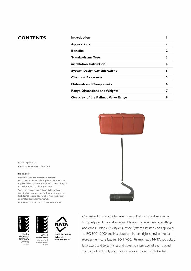
Committed to sustainable development, Philmac is well renowned
for quality products and services. Philmac manufactures pipe fittings
and valves under a Quality Assurance System assessed and approved
to ISO 9001-2000 and has obtained the prestigious environmental
management certification ISO 14000. Philmac has a NATA accredited
laboratory and tests fittings and valves to international and national
standards. Third party accreditation is carried out by SAI Global.
NATA AccreditedLaboratoryNumber: 14673
Disclaimer
Please note that the information, opinions, recommendations and advice given in this manual are supplied only to provide an improved understanding of the technical aspects of fitting systems.
So far as the law allows, Philmac Pty Ltd will not accept liability in respect of any loss or damage of any kind claimed to arise as a result of reliance upon any information claimed in this manual.
Please refer to our Terms and Conditions of sale.
Published June 2008
Reference Number: TMTV001-0608
Introduction 1
Applications 2
Benefits 2
Standards and Tests 3
installation Instructions 4
System Design Considerations 5
Chemical Resistance 5
Materials and Components 6
Range Dimensions and Weights 7
Overview of the Philmac Valve Range 8
CONTENTS

TROUGH VALVES TECHNICAL MANUAL 1
Look, No Arms!Your stock can't knock the Philmac trough valve.
One valve suits different tank arrangements
Side Entry Bottom Entry Overhead Entry
With no lever arm, Philmac's submersed trough valve has virtually eliminating the risk of damage by stock.
The float is UV stabilised and easily adjusted from abover the water line.
And because the float is bright orange, you'll be able to see from a distance that it's in the right place and at the right level.
The trough valve is designed to handle high and low water pressure and works
effectively when installed at any angle.
The unit is available in various sizes to suit most popular drinking troughs and comes in high impact polypropylene or
corrosion-resistant quality brass.

2 TROUGH VALVES TECHNICAL MANUAL
TROUGH VALVES
Philmac’s unique and compact trough valve is essentially a float valve but has been
designed specifically for stock troughs. The valve hugs the trough wall and has no long
lever arm, virtually eliminating the risk of damage caused by stock. By using a cord/float
attachment, stock are no longer able to damage levers or manipulate flow.
The extensive range includes quality brass valves and high impact, UV resistant
polypropylene valves. The brass version comes with a stainless steel seat ensuring
longevity of the product.
This Australia made product is not only robust but versatile as it can be installed in a
horizontal or vertical position within the trough.
Fast and Easy Installation•Multi-positionInstallation:The valves
have been designed to work in either a
vertical or horizontal position for flexible
installation.
• BSPInletThreads: The Rural, Irrigation
and Plumbing sectors use British
Standard Pipe (BSP) threads as a
standard. Philmac also uses these thread
types across the valve range to ensure
compatibility with other threaded fittings
and make installation easy.
•NPTInletThreads: Philmac offers
a complete set of valves with NPT
threads.
•CordAttachment: The cord is easily
attached to the float and therefore
adjustment of the cord is a quick and
simple process.
Complete Security• ReliableOperation: Consistent high
quality injection moulded plastic bodies
or machined brass plus a stainless
steel lever arm and stainless steel seat
(brass version) means years of reliable
operation.
•CorrosionResistant:Manufactured
with plastic, stainless steel and brass
components which all have a high
degree of corrosion resistance ensuring
the longevity of the valve in harsh
agricultural conditions.
• LeverDamage: Stock can no longer
stampede/damage lever or force
unnecessary water out of valve, as the
float operates independently of the
small lever on the valve.
High Performance•Manufacturedfromadvancedthermoplasticmaterials:Philmac
plastic trough valves are manufactured
from lightweight high performance
thermoplastic materials, which have
excellent impact, UV and corrosion
resistance.
• Lowpressureshutoff:Trough valves
are designed to seal off with very low
pressure providing there is water in the
tank to provide upthrust on the float.
Complete Coverage•Widerange:The range of trough valves
is comprehensive and includes sizes
¾", 1" and 1¼" (DN20, 25 and 32).
BENEFITS
Agriculture:Stock troughs and tanks.
APPLICATIONS

TROUGH VALVES TECHNICAL MANUAL 3
Philmac’s range of trough valves are
designed to comply with the following
standards and undertake a range of
tests to ensure they comply with these
standards.
TestsShutOffTest:Valves are tested for shut
off against a hydrostatic water pressure of
300 kPa (43 psi) or 3 bar.
StandardsAS/ISO7.1, Pipe threads where pressure
joints are made on the threads. Part 1
Dimensions, tolerances and designations.
(BSP threads)
AS1722.1: Pipe threads of Whitworth
form part 1: sealing pipe threads.
(BSP threads)
ANSI/ASMEB1.20.1,Pipe threads,
General purpose (inch). (NPT threads)
ASTMF1498, Standard specification for
tapered pipe threads 60° for thermoplastic
pipe and fittings. (NPT threads)
STANDARDS & TESTS
TR
OU
GH
VA
LVE
S

4 TROUGH VALVES TECHNICAL MANUAL
TROUGH VALVES OPERATION & INSTALLATION INSTRUCTIONS
The Philmac trough valves operate by opening and closing a plunger against a seat through the action of a lever attached to a float. As
the water level drops, the float and lever move in a downward direction and the plunger moves away from the seat opening the valve.
When the water level rises, the float and lever move in an upwards direction and the plunger moves towards the seat until it sits firmly
against the seat and shuts the valve off.
1. Apply PTFE tape or approved sealant to the thread ensuring sufficient is applied to ensure a watertight seal.
1. For overhead installation the lever needs to be relocated by unscrewing the pin from the body.
1. Insert the cord through bottom hole of the float, ensure the top of the float is BELOW the rim of the trough then place the cord around the right hand lug. Make a loop.
2. Twist the loop. 3. Place it over the left hand lug and pull tight.
2. Screw into female thread by hand until firm.
2. Rotate the lever by 180° and reinsert the pin through the lower hole (upper hole is for the standard installation). (Refer page 6 for pin locations).
3. Using a pipe wrench or multigrips on the body of the valve screw it into the female thread until tight. Where necessary ensure the female thread is held stationary to avoid it from moving.
3. Installation position.
Setting the Float
Conversion for Overhead Entry

TROUGH VALVES TECHNICAL MANUAL 5
SYSTEM DESIGN CONSIDERATIONS
MaximumOperatingPressure:
400 kPa or 58 psi (¾” brass only); and
300 kPa or 43 psi (all other valves) at 200C.
Threads: Available in either BSP
(Whitworth form), or NPT
Sealingthreads: Philmac recommends
sealing threads with PTFE tape. Other
approved sealants for plastic or brass
materials can be used providing the
sealant does not enter the valve where it
may cause damage.
Operatingtemperature:Connection is
cold water (less than 200C) rated.
Weathering: All plastic materials used
contain pigments to provide excellent
protection against degradation from
ultra-violet (UV) radiation. However long-
term continuous exposure to UV is not
recommended and plastic components
should ideally be protected.
Flow Rates (Litres/min)
Inlet Pressure
(kPa)
Inlet Size
¾” Brass (DN20)
¾” Plastic (DN20)
1” Brass(DN25)
1” Plastic(DN25)
1 ¼” Brass (DN32)
1 ¼” Plastic (DN32)
25 32 33 37 33 57 60
50 38 42 48 42 70 76
75 46 49 58 49 85 92
100 53 57 67 57 99 108
150 64 70 83 70 121 132
200 74 82 96 82 140 154
250 83 91 106 91 157 172
300 91 100 114 100 175 187
400 106 - - - - -
CHEMICAL RESISTANCE
Philmac’s trough valves are primarily designed
to convey water. However there may
be occasions where the water contains
chemicals and/or alternative fluids need to
be controlled. The following table is provided
as a guide only for the compatibility of
various chemicals and/or alternative fluids to
Philmac trough valves. The mixing together
of chemicals may affect the compatibility.
Chemical
CompatibilityTroughValve
- Plastic
TroughValve
- BrassAcetic acid (10%) R NAcetic acid (50%) N NAlcohol (ethanol) N NAmmonium nitrate R NAntifreeze R RBrine R NCalcium carbonate RCalcium chloride N NCalcium nitrate NCalcium sulphate NChlorine water N NCitric Acid N NCopper Sulphate >5% N NDiesel (fuel) R REthyl alcohol (ethanol) N NHydrochloric acid (10%) N NHydrochloric acid (30%) N NKerosene R RLubricating oils (not synthetic) R RMagnesium nitrate RMagnesium sulphate R RMineral oils R RNitric acid (10%) N NNitric acid (40%) N NOlive oil NOrange juice RPetrol RPhosphoric acid (85%) N NDrinking water R RPotassium chloride R RPotassium nitrate R RPotassium sulphate RSodium bicarbonate RSodium hypochlorite (<10%) N NSulphuric acid (10%) N NSulphuric acid (30%) N NUrea R RZinc nitrate NZinc sulphate N
N = Consult Philmac R = ResistantEmpty Cell = No data available
Note recommendations based on fluids at 200 C or less
TR
OU
GH
VA
LVE
S
Flow Rates (US Gallons/min)
Inlet Pressure
(psi)
Inlet Size
¾” Brass (DN20)
¾” Plastic (DN20)
1” Brass(DN25)
1” Plastic(DN25)
1 ¼” Brass (DN32)
1 ¼” Plastic (DN32)
5 9.3 9.6 10.9 9.6 16.6 17.6
10 11.7 12.6 14.6 12.6 21.6 23.4
15 13.9 15.3 18.0 15.3 26.3 28.7
20 16.0 17.7 21.0 17.7 30.7 33.5
25 18.0 19.9 23.6 19.9 34.8 37.8
30 19.9 21.8 25.8 21.8 38.5 41.6
35 21.6 23.5 27.7 23.5 42.0 44.9
40 23.2 25.0 29.2 25.0 45.1 47.7
50 26.0 - - - - -
55 27.0 - - - - -
6 TROUGH VALVES TECHNICAL MANUAL
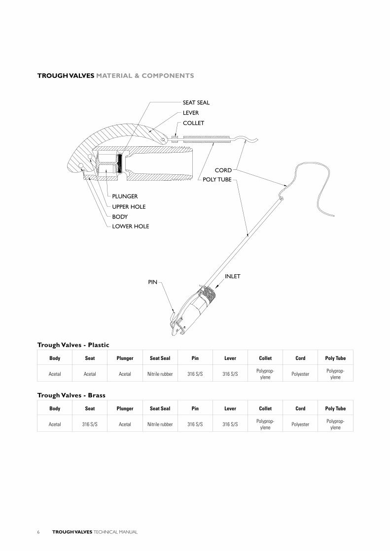
TROUGH VALVES MATERIAL & COMPONENTS
Trough Valves - Plastic
Body Seat Plunger Seat Seal Pin Lever Collet Cord Poly Tube
Acetal Acetal Acetal Nitrile rubber 316 S/S 316 S/S Polyprop-ylene Polyester Polyprop-
ylene
Trough Valves - Brass
Body Seat Plunger Seat Seal Pin Lever Collet Cord Poly Tube
Acetal 316 S/S Acetal Nitrile rubber 316 S/S 316 S/S Polyprop-ylene Polyester Polyprop-
ylene
SEAT SEAL
CORD
PLUNGER
UPPER HOLE
LOWER HOLE
PIN
BODY
POLY TUBE
LEVER
COLLET
INLET

TROUGH VALVES TECHNICAL MANUAL 7
TROUGH VALVES RANGE & DIMENSIONS
B
C
A
TR
OU
GH
VA
LVE
S
Thread Size(A)
Nominal Size
Part Number B C
BSP Threads NPT Threads
¾” DN20 AQ400P AQ400P-NPT 47 127
1” DN25 AQ500P AQ500P-NPT 55 148
1 ¼” DN32 AQ600P AQ600P-NPT 62 166
Trough Valve - PLASTIC Body
Thread Size(A)
Nominal Size
Part Number B C
BSP Threads NPT Threads
¾” DN20 AQ100B AQ100B-NPT 47 127
1” DN25 AQ200B AQ200B-NPT 55 148
1 ¼” DN32 AQ300B AQ300B-NPT 62 166
All dimensions in millimetres unless otherwise stated
Trough Valve - BRASS Body

8 TROUGH VALVES TECHNICAL MANUAL
Valves play an integral part in the performance, management and control of water quality,
flow and pressure within a pipe system. Philmac manufacture a broad range of valves.
Each valve is designed to cater for an array of applications. Whether you want high flow,
high shut-off, high pressure, compact size, plastic or metal, tapered or parallel threads,
solid levers or chain/rope levers (with a choice in lever length).
Philmac has the right valve for you!
OVERVIEW OF THE PHILMAC VALVE RANGE
Sleeve Horizontal Float Servo Tank Cistern Ball Foot/Non-Return Trough High Flow Float Air Release Ratio Floats
Primary Application
Stock Water
Mains Water Connection
Commercial/Industrial
Pump
Trough
Tanks
Pipes
Features
Hot Water Application (95°C) Max.)
Potable Water Approval (4020)
Underwater installation With Cord Attachment
Lever length options
Recycled Water Identification Option
Technical
Maximum Flow Rate (L/min) 238 496 2820 10.4 1680 900 187 330 2260C & 46000D
Maximum Pressure Rating (kPa) 1000 1400 2000 3500 1400 1400 300A 620B 1400 3500
Connection Type (Inlet) BSP BSP BSP BSP BSP BSP BSP BSP BSP BSP or Flanged BSW
Connection Type (Outlet) BSP BSP BSP BSP BSP BSP or Flanged
Sizes ¾” & 1” (DN20 & 25) ½” to 2” (DN15 to 50) 1 ½” to 3” (DN40 to 80) ½” (DN15) ½” to 2” (DN15 to 50) ½” to 2” (DN15 to 50) ¾” to 1 ¼” (DN20 to 32) 1” – 2” (DN25 to 50) 1” (DN25) ½” to 6” 3” to 10”
VALVE RANGE QUICK REFERENCE GUIDE
A 400 kPa for ¾” BrassB Shutoff pressure varies with valve sizeC ScrewedD Flanged

TROUGH VALVES TECHNICAL MANUAL 9
Sleeve Horizontal Float Servo Tank Cistern Ball Foot/Non-Return Trough High Flow Float Air Release Ratio Floats
Primary Application
Stock Water
Mains Water Connection
Commercial/Industrial
Pump
Trough
Tanks
Pipes
Features
Hot Water Application (95°C) Max.)
Potable Water Approval (4020)
Underwater installation With Cord Attachment
Lever length options
Recycled Water Identification Option
Technical
Maximum Flow Rate (L/min) 238 496 2820 10.4 1680 900 187 330 2260C & 46000D
Maximum Pressure Rating (kPa) 1000 1400 2000 3500 1400 1400 300A 620B 1400 3500
Connection Type (Inlet) BSP BSP BSP BSP BSP BSP BSP BSP BSP BSP or Flanged BSW
Connection Type (Outlet) BSP BSP BSP BSP BSP BSP or Flanged
Sizes ¾” & 1” (DN20 & 25) ½” to 2” (DN15 to 50) 1 ½” to 3” (DN40 to 80) ½” (DN15) ½” to 2” (DN15 to 50) ½” to 2” (DN15 to 50) ¾” to 1 ¼” (DN20 to 32) 1” – 2” (DN25 to 50) 1” (DN25) ½” to 6” 3” to 10”

www.philmac.com.au
Philmac Sales
AUSTRALIA
53-59DeedsRoadNorthPlymptonSouthAustralia AUSTRALIA5037
Telephone 1800755899(withinAustralia)Facsimile 1800244688(withinAustralia)Email [email protected] www.philmac.com.au
NEWZEALAND,ASIAPACIFIC,SEASIA, JAPAN,SOUTHAMERICA&OTHERAREAS
53-59DeedsRoadNorthPlymptonSouthAustralia AUSTRALIA5037Telephone +61883009217
Facsimile +61883009390Email [email protected] www.philmac.com.au
PhilmacUKisatradenameof GlynwedPipeSystemsLtd. Companynumber1698059.
RegisteredOffice: WalsallRoad NortonCanes Cannock Staffodshire WS119NS UNITEDKINGDOM
UNITEDKINGDOM,IRELAND, EUROPE,MIDDLEEAST&AFRICA
DiplocksWayHailshamEastSussexUNITEDKINGDOMBN273JF
Telephone +441323847323Facsimile +441323844775Email [email protected] www.philmac.co.uk
NORTH&CENTRALAMERICA
POBox290995PhelanCaliforniaUSA92329
Cell +1(760)2174075Facsimile +1(760)8680470Email [email protected] www.philmacinc.com