
Troubleshooting Lightweight Access...
14
CHAPTER 4-1 Cisco Aironet 1130AG Series Access Point Hardware Installation Guide OL-8369-05 4 Troubleshooting Lightweight Access Points This chapter provides troubleshooting procedures for basic problems with the 1130AG series lightweight access point (model: AIR-LAP1131AG or AIR-LAP1131G). For the most up-to-date, detailed troubleshooting information, refer to the Cisco Technical Support and Documentation website at the following URL: http://www.cisco.com/en/US/products/hw/wireless/tsd_products_support_category_home.html Sections in this chapter include: • Guidelines for Using 1130AG Series Lightweight Access Points, page 4-2 • Checking the Lightweight Access Point LEDs, page 4-2 • Low Power Condition for Lightweight Access Points, page 4-6 • Manually Configuring Controller Information Using the Access Point CLI, page 4-8 • Returning the Access Point to Autonomous Mode, page 4-9 • Obtaining the Autonomous Access Point Image File, page 4-11 • Connecting to the Access Point Console Port, page 4-12 • Obtaining the TFTP Server Software, page 4-13
Transcript of Troubleshooting Lightweight Access...
Cisco Aironet 1130AOL-8369-05
C H A P T E R 4
bsite
Troubleshooting Lightweight Access Points
This chapter provides troubleshooting procedures for basic problems with the 1130AG serieslightweight access point (model: AIR-LAP1131AG or AIR-LAP1131G). For the most up-to-date,detailed troubleshooting information, refer to the Cisco Technical Support and Documentation weat the following URL:
http://www.cisco.com/en/US/products/hw/wireless/tsd_products_support_category_home.html
Sections in this chapter include:
• Guidelines for Using 1130AG Series Lightweight Access Points, page 4-2
• Checking the Lightweight Access Point LEDs, page 4-2
• Low Power Condition for Lightweight Access Points, page 4-6
• Manually Configuring Controller Information Using the Access Point CLI, page 4-8
• Returning the Access Point to Autonomous Mode, page 4-9
• Obtaining the Autonomous Access Point Image File, page 4-11
• Connecting to the Access Point Console Port, page 4-12
• Obtaining the TFTP Server Software, page 4-13
4-1G Series Access Point Hardware Installation Guide
Chapter 4 Troubleshooting Lightweight Access PointsGuidelines for Using 1130AG Series Lightweight Access Points
notisco
withess
esss 1
r the
n
bling
t andtatus.
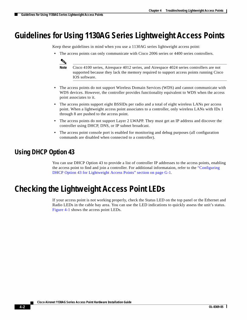
Guidelines for Using 1130AG Series Lightweight Access PointsKeep these guidelines in mind when you use a 1130AG series lightweight access point:
• The access points can only communicate with Cisco 2006 series or 4400 series controllers.
Note Cisco 4100 series, Airespace 4012 series, and Airespace 4024 series controllers are supported because they lack the memory required to support access points running CIOS software.
• The access points do not support Wireless Domain Services (WDS) and cannot communicateWDS devices. However, the controller provides functionality equivalent to WDS when the accpoint associates to it.
• The access points support eight BSSIDs per radio and a total of eight wireless LANs per accpoint. When a lightweight access point associates to a controller, only wireless LANs with IDthrough 8 are pushed to the access point.
• The access points do not support Layer 2 LWAPP. They must get an IP address and discovecontroller using DHCP, DNS, or IP subnet broadcast.
• The access point console port is enabled for monitoring and debug purposes (all configuratiocommands are disabled when connected to a controller).
Using DHCP Option 43You can use DHCP Option 43 to provide a list of controller IP addresses to the access points, enathe access point to find and join a controller. For additional informataion, refer to the“ConfiguringDHCP Option 43 for Lightweight Access Points” section on page G-1.
Checking the Lightweight Access Point LEDsIf your access point is not working properly, check the Status LED on the top panel or the EtherneRadio LEDs in the cable bay area. You can use the LED indications to quickly assess the unit’s sFigure 4-1 shows the access point LEDs.
4-2Cisco Aironet 1130AG Series Access Point Hardware Installation Guide
OL-8369-05

Chapter 4 Troubleshooting Lightweight Access PointsChecking the Lightweight Access Point LEDs
Figure 4-1 Access Point LEDs
Note To view the Ethernet and Radio LEDs you must open the access point cover (refer to the“Opening theAccess Point Cover” section on page 2-11).
Note When the access point cover is opened, the Status LED colors are not visible.
Note There can be slight color variations in the Status LED of each access point.
1 Status LED 3 Ethernet LED
2 Access point cover 4 Radio LED
1218
02
4
3
2
1
4-3Cisco Aironet 1130AG Series Access Point Hardware Installation Guide
OL-8369-05
Chapter 4 Troubleshooting Lightweight Access PointsChecking the Lightweight Access Point LEDs
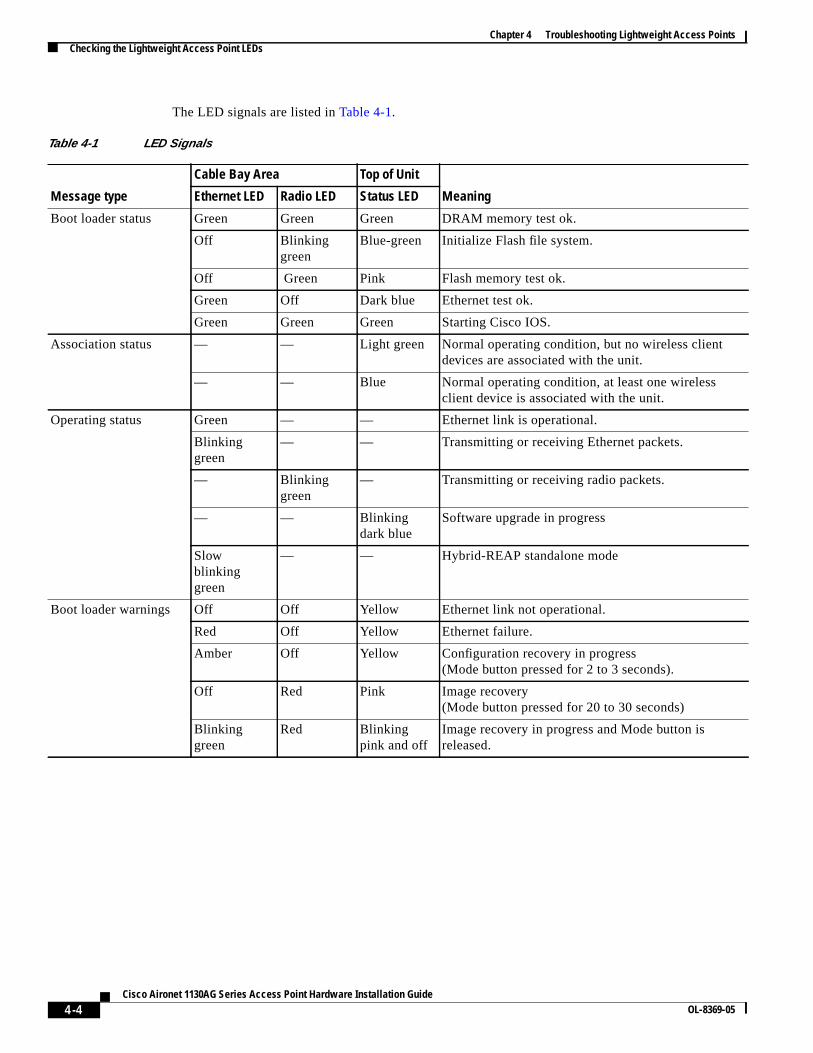
The LED signals are listed inTable 4-1.
Table 4-1 LED Signals
Message type
Cable Bay Area Top of Unit
MeaningEthernet LED Radio LED Status LED
Boot loader status Green Green Green DRAM memory test ok.
Off Blinkinggreen
Blue-green Initialize Flash file system.
Off Green Pink Flash memory test ok.
Green Off Dark blue Ethernet test ok.
Green Green Green Starting Cisco IOS.
Association status — — Light green Normal operating condition, but no wireless clientdevices are associated with the unit.
— — Blue Normal operating condition, at least one wirelessclient device is associated with the unit.
Operating status Green — — Ethernet link is operational.
Blinkinggreen
— — Transmitting or receiving Ethernet packets.
— Blinkinggreen
— Transmitting or receiving radio packets.
— — Blinkingdark blue
Software upgrade in progress
Slowblinkinggreen
— — Hybrid-REAP standalone mode
Boot loader warnings Off Off Yellow Ethernet link not operational.
Red Off Yellow Ethernet failure.
Amber Off Yellow Configuration recovery in progress(Mode button pressed for 2 to 3 seconds).
Off Red Pink Image recovery(Mode button pressed for 20 to 30 seconds)
Blinkinggreen
Red Blinkingpink and off
Image recovery in progress and Mode button isreleased.
4-4Cisco Aironet 1130AG Series Access Point Hardware Installation Guide
OL-8369-05

Chapter 4 Troubleshooting Lightweight Access PointsChecking the Lightweight Access Point LEDs
g
.
Boot loader errors Red Red Red DRAM memory test failure.
Off Red Blinking redand blue
Flash file system failure.
Off Amber Blinking redandblue-green
Environment variable (ENVAR) failure.
Amber Off Blinking redand yellow
Bad MAC address.
Red Off Blinking redand off
Ethernet failure during image recovery.
Amber Amber Blinking redand off
Boot environment error.
Red Amber Blinking redand off
No Cisco IOS image file.
Amber Amber Blinking redand off
Boot failure.
Cisco IOS errors Blinkingamber
— — Transmit or receive Ethernet errors.
— Blinkingamber
— Maximum retries or buffer full occurred on the radio.
Red Red Amber Software failure; try disconnecting and reconnectinunit power.
— — Amber General warning, insufficient inline power (see the“Low Power Condition for Lightweight AccessPoints” section).
Controller status — — Alternatinggreen, red ,and amber1
Connecting to the controller.
Note If the access point remains in this mode formore than five minutes, the access point isunable to find the controller. Ensure a DHCPserver is available or that controllerinformation is configured on the access point
— — Blinkingdark blue
Loading the access point image file.
1. This status indication has the highest priority and overrides other status indications.
Table 4-1 LED Signals (continued)
Message type
Cable Bay Area Top of Unit
MeaningEthernet LED Radio LED Status LED
4-5Cisco Aironet 1130AG Series Access Point Hardware Installation Guide
OL-8369-05
Chapter 4 Troubleshooting Lightweight Access PointsLow Power Condition for Lightweight Access Points
werrotocol,
netwerht not
point.ct
isgle
OSe ismode, the
eds
isco
r.
s, theos
ationreport
Low Power Condition for Lightweight Access Points
Warning This product must be connected to a Power over Ethernet (PoE) IEEE 802.3af compliant power sourceor an IEC60950 compliant limited power source. Statement 353
The lightweight access point can be powered from the 48-VDC power module or from an in-line posource. The access point supports the IEEE 802.3af power standard, Cisco Pre-Standard PoE pand Cisco Intelligent Power Management for in-line power sources.
For full operation, the access point requires 12.95 W of power. The power module and Cisco Airopower injectors are capable of supplying the required power for full operation, but some inline posources are not capable of supplying 12.95 W. Also, some high-power inline power sources, migbe able to provide 12.95 W of power to all ports at the same time.
Note An 802.3af compliant switch (Cisco or non-Cisco) is capable of supplying sufficient power for fulloperation.
Note If your access point is connected to in-line power, do not connect the power module to the accessUsing two power sources on the access point might cause the access point to shut down to proteinternal components and might cause the switch to shut down the port to which the access pointconnected. If your access point shuts down, you must remove all power and reconnect only a sinpower source.
On power up, the access point is placed into low power mode (both radios are disabled), Cisco Isoftware loads and runs, and power negotiation determines if sufficient power is available. If thersufficient power then both radios are turned on; otherwise, the access point remains in low powerwith one or both radios disabled to prevent a possible over-current condition. In low power modeaccess point activates the Status LED low power error indication (see the“Checking the LightweightAccess Point LEDs” section on page 4-2).
Intelligent Power ManagementThe access point requires 12.95 W of power for full power operation with both radios, but only ne6.3 W of power when operating in low power mode with both radios disabled. To help avoid anover-current condition with low power sources and to optimize power usage on Cisco switches, Cdeveloped Intelligent Power Management, which uses Cisco Discovery Protocol (CDP) to allowpowered devices (such as your access point) to negotiate with a Cisco switch for sufficient powe
The access point supports Intelligent Power Management and as a result of the power negotiationaccess point will either enter full power mode or remain in low power mode with one or both radidisabled.
Note Independent of the power negotiations, the access point hardware also uses the 802.3af classificscheme to indicate the power required from the power source. However, the power source cannotthe power available to the access point unless the power source also supports Intelligent PowerManagement.
4-6Cisco Aironet 1130AG Series Access Point Hardware Installation Guide
OL-8369-05
Chapter 4 Troubleshooting Lightweight Access PointsLow Power Condition for Lightweight Access Points
o thers full
ne or
tee
der
iscoportgure
ly
ort
ent0950
Some Cisco switches that are capable of supplying sufficient power require a software upgrade tsupport Intelligent Power Management. If the software upgrade is not desired, you can configureaccess point to operate in pre-standard compatibility mode and the access point automatically entepower mode if these Cisco switches are detected in the received CDP ID field.
When the access point determines that sufficient power is not available for full-power operation, oboth readios are deactivated and the Status LED turns amber to indicate low power mode (seeTable 4-1).
If your Cisco switch is capable of supplying sufficient power for full operation but the access poinremains in low-power mode, your access point or your switch (or both) might be misconfigured (sTable 4-2.
If your inline power source is not able to supply sufficient power for full operation, you should consithese options (seeTable 4-2):
• Upgrade to a higher-powered switch
• Use a Cisco Aironet power injector on the switch port
• Use the 48-VDC power module to locally power the access point
Configuring Power Using Controller CLI CommandsIntelligent Power Management support is dependent on the version of software resident in the Cswitch that is providing power to the access point. Each Cisco switch should be upgraded to supIntelligent Power Management. Until the software is upgraded, you can use your controller to confithe access point to operate with older switch software using these controller CLI commands:
1) config ap power pre-standard enable <ap>where < ap> is the access point name on the controller
2) config ap power injector enable < ap> <switch port MAC address>(where < ap> is the access point name on the controller
and <switch port MAC address> is the MAC address of the switch port to which theaccess point is connected)
Note Refer to your controller documentation for instructions on using these commands.
You can use these controller CLI commands to inform the access point of the following:
• The Cisco switch does not support Intelligent Power Management but should be able to suppsufficient power.
• A power injector is being used to supply sufficient power and the Cisco switch does not suppIntelligent Power Management.
Caution If the access point receives power through PoE, the output current of the power sourcing equipm(PSE) cannot exceed 400 mA per port. The power source must comply with IEEE 802.3af or IEC6for limited power sources.
4-7Cisco Aironet 1130AG Series Access Point Hardware Installation Guide
OL-8369-05
Chapter 4 Troubleshooting Lightweight Access PointsManually Configuring Controller Information Using the Access Point CLI
lynect
a
withnewot
t. Support
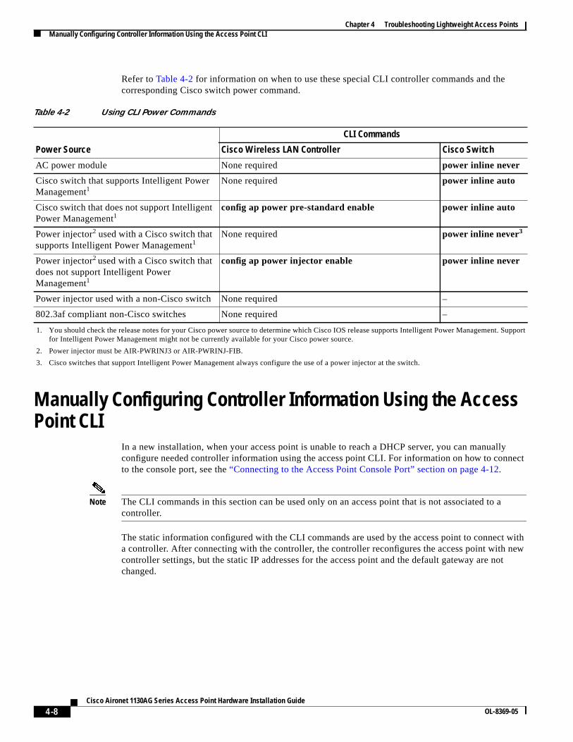
Refer toTable 4-2 for information on when to use these special CLI controller commands and thecorresponding Cisco switch power command.
Manually Configuring Controller Information Using the AccessPoint CLI
In a new installation, when your access point is unable to reach a DHCP server, you can manualconfigure needed controller information using the access point CLI. For information on how to conto the console port, see the“Connecting to the Access Point Console Port” section on page 4-12.
Note The CLI commands in this section can be used only on an access point that is not associated tocontroller.
The static information configured with the CLI commands are used by the access point to connecta controller. After connecting with the controller, the controller reconfigures the access point withcontroller settings, but the static IP addresses for the access point and the default gateway are nchanged.
Table 4-2 Using CLI Power Commands
Power Source
CLI Commands
Cisco Wireless LAN Controller Cisco Switch
AC power module None required power inline never
Cisco switch that supports Intelligent PowerManagement1
1. You should check the release notes for your Cisco power source to determine which Cisco IOS release supports Intelligent Power Managemenfor Intelligent Power Management might not be currently available for your Cisco power source.
None required power inline auto
Cisco switch that does not support IntelligentPower Management1
config ap power pre-standard enable power inline auto
Power injector2 used with a Cisco switch thatsupports Intelligent Power Management1
2. Power injector must be AIR-PWRINJ3 or AIR-PWRINJ-FIB.
None required power inline never3
3. Cisco switches that support Intelligent Power Management always configure the use of a power injector at the switch.
Power injector2 used with a Cisco switch thatdoes not support Intelligent PowerManagement1
config ap power injector enable power inline never
Power injector used with a non-Cisco switch None required –
802.3af compliant non-Cisco switches None required –
4-8Cisco Aironet 1130AG Series Access Point Hardware Installation Guide
OL-8369-05

Chapter 4 Troubleshooting Lightweight Access PointsReturning the Access Point to Autonomous Mode
cess
ally
LI
d:
hatt isoint is
Configuring Controller InformationTo manually configure controller information on a new (out-of -the-box) access point using the acpoint CLI interface, you can use these EXEC mode CLI commands:
AP# lwapp ap ip address < IP address > < subnet mask >AP# lwapp ip default-gateway IP-addressAP# lwapp controller ip address IP-addressAP# lwapp ap hostname name
Where name is the access point name on the controller.
Note The default (out-of-box) Enable password isCisco.
Clearing Manually Entered Controller InformationWhen you move your access point to a different location in your network, you must clear the manuentered controller information to allow your access point to associate with a different controller.
Note This command requires the controller configured Enable password to enter the CLI EXEC mode.
To clear or remove the manually entered controller information, you can use these EXEC mode Ccommands:
clear lwapp ap ip addressclear lwapp ip default-gatewayclear lwapp controller ip addressclear lwapp ap hostname
Manually Resetting the Access Point to DefaultsYou can manually reset your access point to default settings using this EXEC mode CLI comman
Note This command requires the controller configured Enable password to enter the CLI EXEC mode.
clear lwapp private-config
Returning the Access Point to Autonomous ModeYou can return a lightweight access point to autonomous mode by loading a Cisco IOS release tsupports autonomous mode (such as Cisco IOS Release 12.3(7)JA or earlier). If the access poinassociated to a controller, you can use the controller to load the Cisco IOS release. If the access pnot associated to a controller, you can load the Cisco IOS release using TFTP.
4-9Cisco Aironet 1130AG Series Access Point Hardware Installation Guide
OL-8369-05

Chapter 4 Troubleshooting Lightweight Access PointsReturning the Access Point to Autonomous Mode
d:
LED
ODE
n is
een
LED
Using a WLAN Controller to Return the Access Point to Autonomous ModeFollow these steps to revert from lightweight mode to autonomous mode using a controller:
Step 1 Log into the CLI on the controller to which the access point is associated and enter this comman
config ap tftp-downgrade tftp-server-ip-address filename access-point-name(where:
a) tftp-server-ip-address is the IP address of the TFTP serverb) filename is the full path and filname of the access point image file, such asD:/Images/ c1130-k9w7-tar.123-7.JA.ta rc) access-point-name is the name that identifies the access point on theocntroller.)
Step 2 Wait until the access point reboots, as indicated by all LEDs turning green followed by the Statusblinking green.
Step 3 After the access point reboots, reconfigure it using the access point GUI or the CLI.
Using the MODE Button to Return the Access Point to Autonomous ModeFollow these steps to return a lightweight access point to autonomous mode using the access point Mbutton and a TFTP server:
Note The access point MODE button is enabled by default, but you need to verify that the MODE buttoenabled (see the“MODE Button Setting” section on page 4-11.
Step 1 Set the static IP address of the PC on which your TFTP server software runs to an address betw10.0.0.2 and 10.0.0.30.
Step 2 Make sure that the PC contains the access point image file (such asc1130-k9w7-tar.123-7.JA.tar for an1130 series access point) in the TFTP server folder and that the TFTP server is activated.
Step 3 Rename the access point image file in the TFTP server folder toc1130-k9w7-tar.default.
Step 4 Connect the PC to the access point using a Category 5 (CAT5) Ethernet cable.
Step 5 Disconnect power from the access point.
Step 6 Press and hold theMODE button while you reconnect power to the access point.
Step 7 Hold theMODE button until the Radio LED turns red (approximately 20 to 30 seconds) and thenrelease.
Step 8 Wait until the access point reboots, as indicated by all LEDs turning green followed by the Statusblinking green.
Step 9 After the access point reboots, reconfigure it using the access point GUI or the CLI.
4-10Cisco Aironet 1130AG Series Access Point Hardware Installation Guide
OL-8369-05

Chapter 4 Troubleshooting Lightweight Access PointsObtaining the Autonomous Access Point Image File
se
these
an
k
k
k
MODE Button SettingThe lightweight access point MODE button is configured from your Cisco Wireless LAN Controller. Uthese controller CLI commands to view and configure the MODE button:
1) config ap rst-button enable <access-point-name>/all2) config ap rst-button disable <access-point-name>/all3) show ap config general <access-point-name>
(Where access-point-name is the name that identifies the access point on theocntroller.)
Obtaining the Autonomous Access Point Image FileThe autonomous access point image file can be obtained from the Cisco.com software center usingsteps:
Note To download software from the Cisco.com software center, you must be a registered user. You cregister from the main Cisco.com web page at this URL:http://cisco.com.
Step 1 Use your Internet browser to access the Cisco Software Center at the following URL:
http://tools.cisco.com/support/downloads/pub/MDFTree.x?butype=wireless
Step 2 Click Access Points > Cisco Aironet 1130 AG Series.
Step 3 Click Cisco Aironet 1130AG Access Point.
Step 4 On the Enter Network Password window, enter your Cisco.com username and password and clicOK .
Step 5 Click IOS.
Step 6 Choose the Cisco IOS release desired, such as 12.3.8.JA.
Step 7 Click WIRELESS LAN for an access point image file, such asc1130-k9w7-tar.123-8.JA.tar.
Step 8 On the Enter Network Password window, enter your Cisco.com username and password and clicOK .
Step 9 On the Security Information window, clickYes to display non-secure items.
Step 10 On the Encryption Software Export Authorization page, read the information and checkYesor No to thequestion asking if the image is for use by you or your organization. Click Submit..
Step 11 If you checked No, enter the requested information and clickSubmit.
Step 12 Click Yes to continue.
Step 13 Click DOWNLOAD .
Step 14 Read and accept the terms and conditions of the Software Download Rules.
Step 15 On the Enter Network Password window, enter your Cisco.com username and password and clicOK .
Step 16 Click Save to download your image file to your hard disk.
Step 17 Select the desired download location on your hard disk and clickSave.
4-11Cisco Aironet 1130AG Series Access Point Hardware Installation Guide
OL-8369-05

Chapter 4 Troubleshooting Lightweight Access PointsConnecting to the Access Point Console Port
t bee port
ort:
nt and
tingsntrol.
point.
Connecting to the Access Point Console PortThe console port is enabled during power up for diagnostic and monitoring purposes, which mighhelpful if the access point is unable to associate to a controller. You can connect a PC to the consolusing a DB-9 to RJ-45 serial cable.
Caution Be careful when handling the access point, the bottom plate might be hot.
Note The Cisco part number for the DB-9 to RJ-45 serial cable is AIR-CONCAB1200. Browse tohttp://www.cisco.com/en/US/ordering/index.shtml to order a serial cable.
Follow these steps to view the power up sequences by connecting to the access point console p
Step 1 Open the access point cover (refer to the“Opening the Access Point Cover” section on page 2-11).
Step 2 Connect a nine-pin, female DB-9 to RJ-45 serial cable to the RJ-45 console port on the access poito the COM port on a computer. The location of the access point console port is shown inFigure 4-2.
Figure 4-2 Console Port Location
Step 3 Set up a terminal emulator on your PC to communicate with the access point. Use the following setfor the terminal emulator connection: 9600 baud, 8 data bits, no parity, 1 stop bit, and no flow co
When you have finished using the console port, you must remove the serial cable from the access
1 Console port
1218
01
1
4-12Cisco Aironet 1130AG Series Access Point Hardware Installation Guide
OL-8369-05

Chapter 4 Troubleshooting Lightweight Access PointsObtaining the TFTP Server Software
TFTP
Obtaining the TFTP Server SoftwareYou can download TFTP server software from several web sites. Cisco recommends the sharewareutility available at this URL:
http://tftpd32.jounin.net
Follow the instructions on the website for installing and using the utility.
4-13Cisco Aironet 1130AG Series Access Point Hardware Installation Guide
OL-8369-05

Chapter 4 Troubleshooting Lightweight Access PointsObtaining the TFTP Server Software
4-14Cisco Aironet 1130AG Series Access Point Hardware Installation Guide
OL-8369-05