TROUBLESHOOTING GUIDE C7000/C7000P/C6000/C70hc/ C6000L
154
TROUBLESHOOTING GUIDE C7000/C7000P/C6000/C70hc/ C6000L 2012.6 Ver.2.0 CS Headqurters
-
Upload
bernardo-hernandez -
Category
Documents
-
view
634 -
download
161
description
TROUBLESHOOTING GUIDE C7000/C7000P/C6000/C70hc/ C6000L
Transcript of TROUBLESHOOTING GUIDE C7000/C7000P/C6000/C70hc/ C6000L

TROUBLESHOOTING GUIDE
C7000/C7000P/C6000/C70hc/ C6000L
2012.6 Ver.2.0
CS Headqurters
Table of contents To prevent trouble I. Adjustment procedure
a. Colors 1. Color calibration procedure ------------------------------------------------------------------------------- 3 2. Maximum density Adjustment ---------------------------------------------------------------------------- 7 3. Density balance adjustment -----------------------------------------------------------------------------21 4. Register paper category ----------------------------------------------------------------------------------23 5. Printer controller calibration -----------------------------------------------------------------------------26
b. Paper 1. Both sides position adjustment -------------------------------------------------------------------------33
To correct trouble II. Image quality
a. Spot 1. Cyclic white spot/black spot -----------------------------------------------------------------------------45
b. Line/Band 1. Line and uneven density countermeasure flow -----------------------------------------------------46 2. White lines (to sub-scan direction) ---------------------------------------------------------------------49 3. Drum humidity memory -----------------------------------------------------------------------------------51 4. Gloss line caused by fusing paper exit roller --------------------------------------------------------52 5. Banding in the main scan direction on halftone image printed on thick paper
(Jitter problem) ---------------------------------------------------------------------------------------------53 6. Line like ripple on image ---------------------------------------------------------------------------------55 7. Banding on Halftone --------------------------------------------------------------------------------------56 8. Waste toner packin---------------------------------------------------------------------------------------- 57 9. Transfer shifts with halftone on thick paper under high humidity -------------------------------58 10. 8mm pitch line on thick paper at low speed printing -----------------------------------------------59 11. Darker image up to 53mm from leading edge or after 53mm from white area
(Developing memory) -------------------------------------------------------------------------------------61 12. Image after white part becomes darker (Developing ghost) -------------------------------------63 13. Image soilage at machine rear side -------------------------------------------------------------------65
c. Soilage 1. Toner spilling ------------------------------------------------------------------------------------------------66 2. Smear on mat-coated paper with half-tone image -------------------------------------------------69
d. Others 1. Darker at the trailing edge of image -------------------------------------------------------------------70 2. Depletion of developer after continuous printing ---------------------------------------------------71 3. Image skew (CD skew : bottom down direction) ---------------------------------------------------72 4. How to maintain consistent color during continuous printing ------------------------------------82
III. Paper conveyance failure
a. Paper conveyance 1. PFU centering error (image suddenly shifts by 5mm) ---------------------------------------------83 2. 2nd side image position adjustment -------------------------------------------------------------------86
b. Others 1. Paper waving -----------------------------------------------------------------------------------------------87 2. Curl or backling at fusing unit ---------------------------------------------------------------------------92
IV. Machine Troubles a. Control 1. Printer gamma offset automatic adjustment does not complete normally after trying
several times ------------------------------------------------------------------------------------------------94 2. Print job is not accepted while machine indicates dehumidifying ------------------------------95 3. Developer spill ----------------------------------------------------------------------------------------------96 4. Either error code 246 or 247 is indicated on the display with ISW -----------------------------97 5. ISW does not complete -----------------------------------------------------------------------------------98
b. Error code 1. C-2451, C-2452, C-2453 and C-2454 occur --------------------------------------------------------99
- 1 -
KONICA MINOLTA Confidential
2. C-2721, Intermediate transfer belt wrapping jam due to separation failure ----------------101 3. C-C101 occurs right after turning ON the power source ---------------------------------------103 4. C-3102 fusing motor abnormality --------------------------------------------------------------------105 5. C-0213 paper ejection abnormality ------------------------------------------------------------------106
c. Others 1. Options cannot be recognized. System configuration display without options ------------107 2. Caution for charging developer to developing unit -----------------------------------------------108 3. Weekly timer setting –Select time for power save does not work normally ----------------109 4. Intermediate transfer belt cleaning blade flipping ------------------------------------------------ 111
V. Options
a. RU-509 /HM-102 1. J-7551 or J-7552 occurs if the guide plate under the entrance of RU-508/509 is
not fully locked -------------------------------------------------------------------------------------------- 113 2. Correction to the RU-509 User's Guide: The curl adjustment reference table ------------ 114 3. Water leakage of HM-101/102 ------------------------------------------------------------------------ 115 4. J-7550 occurs due to mis-detection of the entrance sensor of RU-508/509 -------------- 116 5. Adjustment for scratch on thick paper -------------------------------------------------------------- 118
b. FS-531/612
1. When using the FS-531/FS-612 and binding 2 sheets with 2 stapling positions, a shift in the stapling positions occurs in the direction of the paper feed ------------------139
2. FS-612 board damage due to the wrong description of installation manual ---------------140
c. FS-521 1. FS-521 Staple Jam procedure ------------------------------------------------------------------------141 2. FS-521 When stapling papers, mis-alignment occurs ------------------------------------------145
d. SD-506
1. SD-506 tri-fold adjustment procedure ---------------------------------------------------------------146
e. LS-505 1. LS-505 Mis-alignment in the LS stacke -------------------------------------------------------------147 2. LS-505 The door opens with its rebound -----------------------------------------------------------148 3. LS-505 BELT 216L(15AV76530) Replacement procedure ------------------------------------149
To reduce visit time VI. Image quality
a. Service Tool 1. Developer Ejection Jig ----------------------------------------------------------------------------------157
- 2 -
KONICA MINOLTA Confidential
I-a-1. Color calibration procedure <FLOW>
1. Simple flow (Use IDC sensor only: Default) 2. Standard flow (Using Color density control sensor) *KM recommendation 3. High accuracy flow (in addition to standard flow, use Paper category)
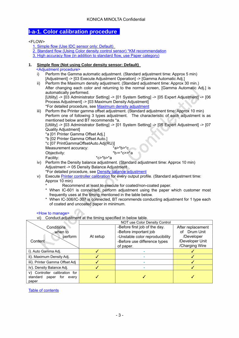
1. Simple flow (Not using Color density sensor: Default)
<Adjustment procedure> i) Perform the Gamma automatic adjustment. (Standard adjustment time: Approx 5 min)
[Adjustment] -> [03 Execute Adjustment Operation] -> [Gamma Automatic Adj.] ii) Perform the Maximum density adjustment. (Standard adjustment time: Approx 30 min.)
After changing each color and returning to the normal screen, [Gamma Automatic Adj.] is automatically performed. [Utility] -> [03 Administrator Setting] -> [01 System Setting] -> [05 Expert Adjustment] -> [06 Process Adjustment] -> [03 Maximum Density Adjustment] *For detailed procedure, see Maximum density adjustment
iii) Perform the Printer gamma offset adjustment. (Standard adjustment time: Approx 10 min) Perform one of following 3 types adjustment. The characteristic of each adjustment is as mentioned below and BT recommends *a. [Utility] -> [03 Administrator Setting] -> [01 System Setting] -> [05 Expert Adjustment] -> [07 Quality Adjustment] *a [01 Printer Gamma Offset Adj.] *b [02 Printer Gamma Offset Auto.] *c [07 PrintGammaOffsetAuto.Adj(RU)] Measurement accuracy: *a>*b>*c Objectivity: *b=*c>>*a Facility: *c>*b>*a
iv) Perform the Density balance adjustment. (Standard adjustment time: Approx 10 min) Adjustment -> 05 Density Balance Adjustment *For detailed procedure, see Density balance adjustment
v) Execute Printer controller calibration for every output profile. (Standard adjustment time: Approx 10 min) * Recommend at least to execute for coated/non-coated paper. * When IC-601 is connected, perform adjustment using the paper which customer most
frequently uses at the timing mentioned in the table below. * When IC-306/IC-307 is connected, BT recommends conducting adjustment for 1 type each
of coated and uncoated paper in minimum.
<How to manage> vi) Conduct adjustment at the timing specified in below table.
NOT use Color Density Control -Before first job of the day. -Before important job -Unstable color reproducibility
Conditions when to
perform Content
At setup -Before use difference types of paper.
After replacement of Drum Unit
/Developer /Developer Unit /Charging Wire
i). Auto Gamma Adj. ✓ - ✓ ii). Maximum Density Adj. ✓ - ✓ iii). Printer Gamma Offset Adj ✓ - ✓ iv). Density Balance Adj. ✓ - ✓ v) Controller calibration for standard paper for every paper
✓ ✓ ✓
Table of contents
- 3 -
KONICA MINOLTA Confidential
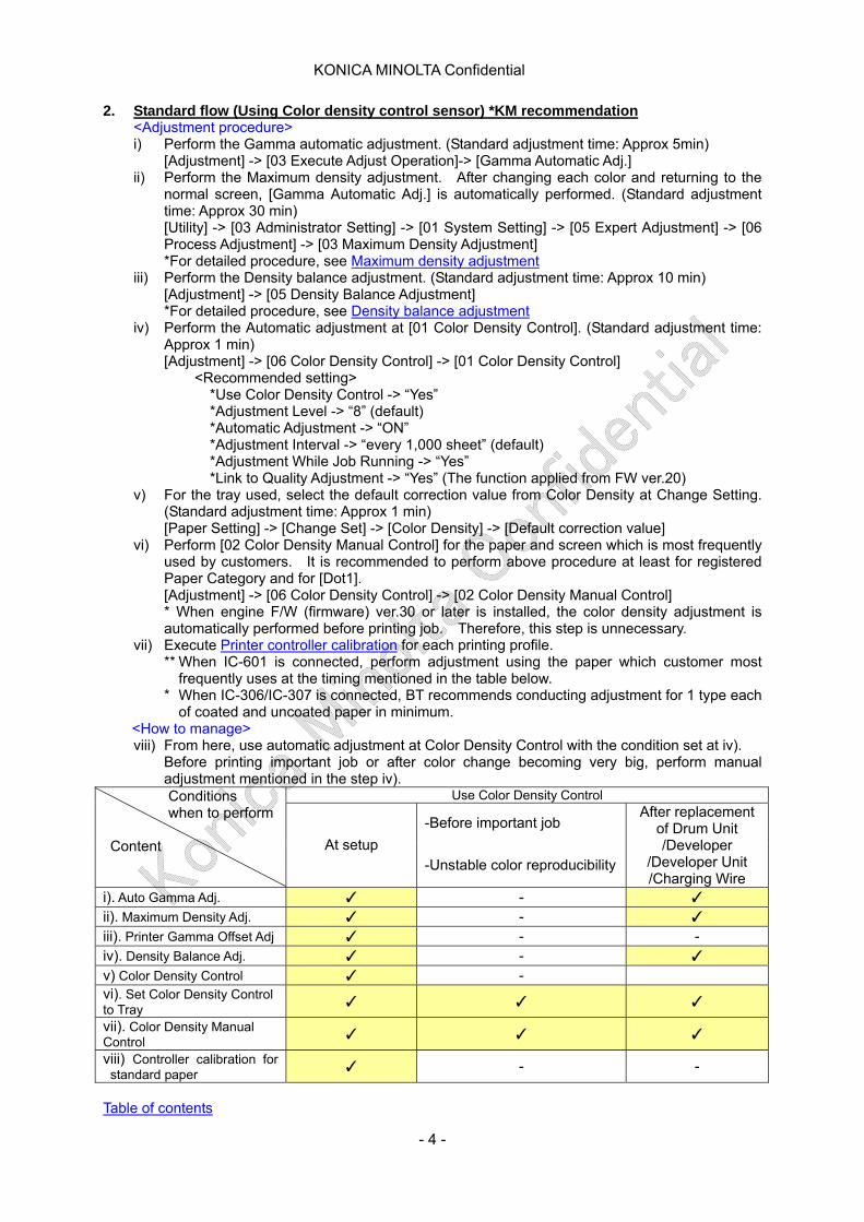
2. Standard flow (Using Color density control sensor) *KM recommendation <Adjustment procedure> i) Perform the Gamma automatic adjustment. (Standard adjustment time: Approx 5min)
[Adjustment] -> [03 Execute Adjust Operation]-> [Gamma Automatic Adj.] ii) Perform the Maximum density adjustment. After changing each color and returning to the
normal screen, [Gamma Automatic Adj.] is automatically performed. (Standard adjustment time: Approx 30 min) [Utility] -> [03 Administrator Setting] -> [01 System Setting] -> [05 Expert Adjustment] -> [06 Process Adjustment] -> [03 Maximum Density Adjustment] *For detailed procedure, see Maximum density adjustment
iii) Perform the Density balance adjustment. (Standard adjustment time: Approx 10 min) [Adjustment] -> [05 Density Balance Adjustment] *For detailed procedure, see Density balance adjustment
iv) Perform the Automatic adjustment at [01 Color Density Control]. (Standard adjustment time: Approx 1 min) [Adjustment] -> [06 Color Density Control] -> [01 Color Density Control]
<Recommended setting> *Use Color Density Control -> “Yes” *Adjustment Level -> “8” (default) *Automatic Adjustment -> “ON” *Adjustment Interval -> “every 1,000 sheet” (default) *Adjustment While Job Running -> “Yes” *Link to Quality Adjustment -> “Yes” (The function applied from FW ver.20)
v) For the tray used, select the default correction value from Color Density at Change Setting. (Standard adjustment time: Approx 1 min) [Paper Setting] -> [Change Set] -> [Color Density] -> [Default correction value]
vi) Perform [02 Color Density Manual Control] for the paper and screen which is most frequently used by customers. It is recommended to perform above procedure at least for registered Paper Category and for [Dot1]. [Adjustment] -> [06 Color Density Control] -> [02 Color Density Manual Control] * When engine F/W (firmware) ver.30 or later is installed, the color density adjustment is automatically performed before printing job. Therefore, this step is unnecessary.
vii) Execute Printer controller calibration for each printing profile. ** When IC-601 is connected, perform adjustment using the paper which customer most
frequently uses at the timing mentioned in the table below. * When IC-306/IC-307 is connected, BT recommends conducting adjustment for 1 type each
of coated and uncoated paper in minimum. <How to manage>
viii) From here, use automatic adjustment at Color Density Control with the condition set at iv). Before printing important job or after color change becoming very big, perform manual adjustment mentioned in the step iv).
Use Color Density Control
-Before important job
Conditions when to perform Content
At setup -Unstable color reproducibility
After replacement of Drum Unit /Developer
/Developer Unit /Charging Wire
i). Auto Gamma Adj. ✓ - ✓ ii). Maximum Density Adj. ✓ - ✓ iii). Printer Gamma Offset Adj ✓ - - iv). Density Balance Adj. ✓ - ✓ v) Color Density Control ✓ - vi). Set Color Density Control to Tray ✓ ✓ ✓
vii). Color Density Manual Control ✓ ✓ ✓
viii) Controller calibration for standard paper ✓ - -
Table of contents
- 4 -
KONICA MINOLTA Confidential
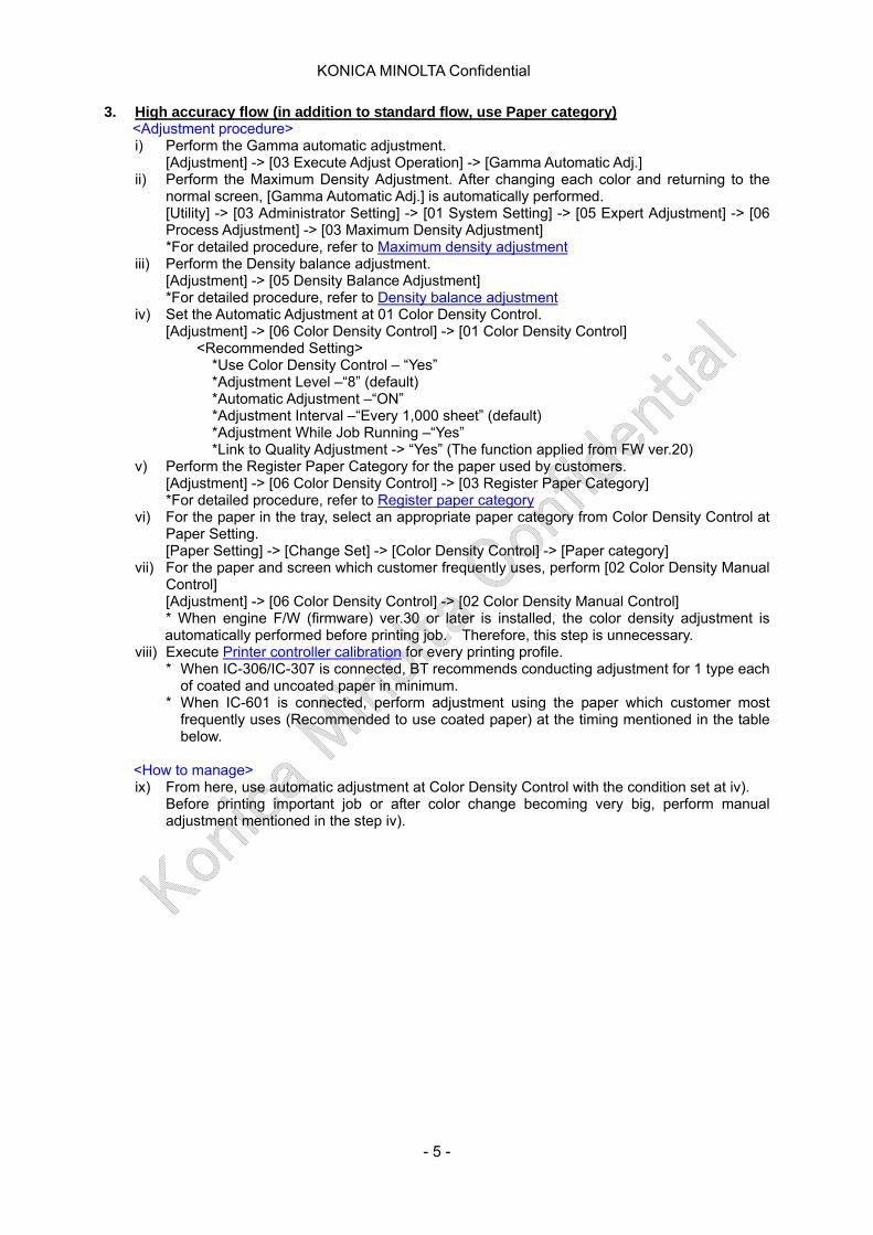
3. High accuracy flow (in addition to standard flow, use Paper category) <Adjustment procedure> i) Perform the Gamma automatic adjustment.
[Adjustment] -> [03 Execute Adjust Operation] -> [Gamma Automatic Adj.] ii) Perform the Maximum Density Adjustment. After changing each color and returning to the
normal screen, [Gamma Automatic Adj.] is automatically performed. [Utility] -> [03 Administrator Setting] -> [01 System Setting] -> [05 Expert Adjustment] -> [06 Process Adjustment] -> [03 Maximum Density Adjustment] *For detailed procedure, refer to Maximum density adjustment
iii) Perform the Density balance adjustment. [Adjustment] -> [05 Density Balance Adjustment] *For detailed procedure, refer to Density balance adjustment
iv) Set the Automatic Adjustment at 01 Color Density Control. [Adjustment] -> [06 Color Density Control] -> [01 Color Density Control]
<Recommended Setting> *Use Color Density Control – “Yes” *Adjustment Level –“8” (default) *Automatic Adjustment –“ON” *Adjustment Interval –“Every 1,000 sheet” (default) *Adjustment While Job Running –“Yes” *Link to Quality Adjustment -> “Yes” (The function applied from FW ver.20)
v) Perform the Register Paper Category for the paper used by customers. [Adjustment] -> [06 Color Density Control] -> [03 Register Paper Category] *For detailed procedure, refer to Register paper category
vi) For the paper in the tray, select an appropriate paper category from Color Density Control at Paper Setting. [Paper Setting] -> [Change Set] -> [Color Density Control] -> [Paper category]
vii) For the paper and screen which customer frequently uses, perform [02 Color Density Manual Control] [Adjustment] -> [06 Color Density Control] -> [02 Color Density Manual Control] * When engine F/W (firmware) ver.30 or later is installed, the color density adjustment is automatically performed before printing job. Therefore, this step is unnecessary.
viii) Execute Printer controller calibration for every printing profile. * When IC-306/IC-307 is connected, BT recommends conducting adjustment for 1 type each
of coated and uncoated paper in minimum. * When IC-601 is connected, perform adjustment using the paper which customer most
frequently uses (Recommended to use coated paper) at the timing mentioned in the table below.
<How to manage> ix) From here, use automatic adjustment at Color Density Control with the condition set at iv).
Before printing important job or after color change becoming very big, perform manual adjustment mentioned in the step iv).
- 5 -
KONICA MINOLTA Confidential
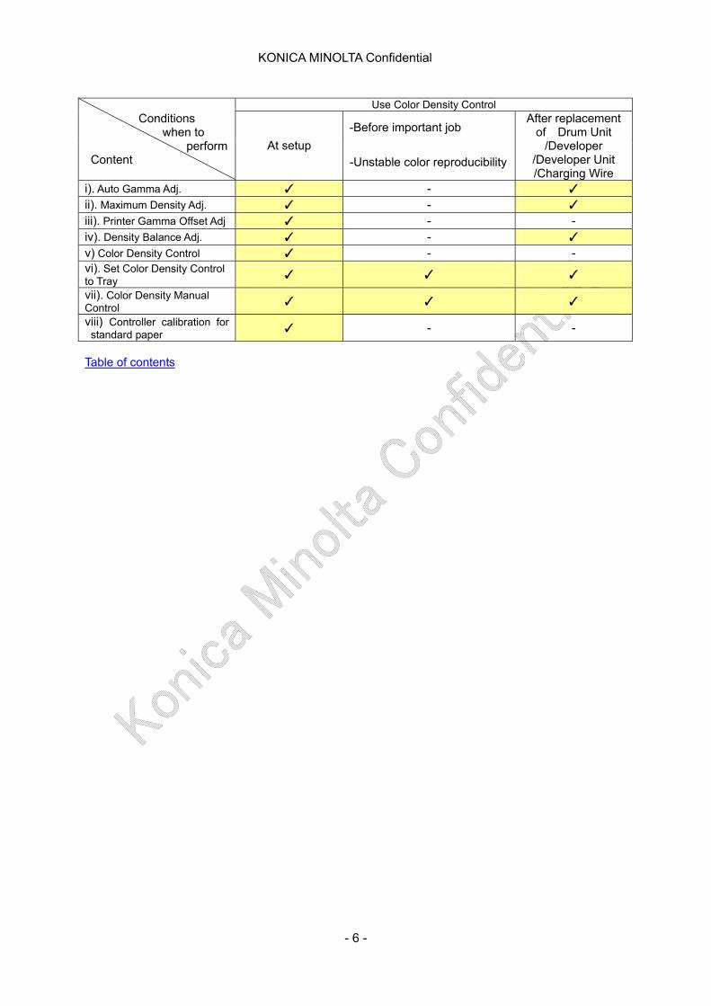
Use Color Density Control
-Before important job Conditions when to
perform Content
At setup -Unstable color reproducibility
After replacement of Drum Unit
/Developer /Developer Unit /Charging Wire
i). Auto Gamma Adj. ✓ - ✓ ii). Maximum Density Adj. ✓ - ✓ iii). Printer Gamma Offset Adj ✓ - - iv). Density Balance Adj. ✓ - ✓ v) Color Density Control ✓ - - vi). Set Color Density Control to Tray ✓ ✓ ✓
vii). Color Density Manual Control ✓ ✓ ✓
viii) Controller calibration for standard paper ✓ - -
Table of contents
- 6 -

KONICA MINOLTA Confidential
I-a-2 Maximum density adjustment 1. Preparation
① Measurement instrument ・ USB memory ・ For IC-601, Color Centro installed PC ・ For IC-306, Command Workstation installed PC ・ For IC-307, use printer server
2. Adjustment procedure
For the adjustment, color spectrometer for controller calibration is used. Therefore, the procedure depends on the connected controller
・ IC-601 connected machine ・ IC-306 connected machine ・ IC-307 connected machine
<IC-601 connected machine>
i) Start [Color Centro]. Input the Destination as follows at Login window. Destination: [Controller IP Address] + [:30081]
ii) Select Calibration of Color Centro window.
- In case of i1Pro: Go to iii) - In case of i1isis: Go to ix)
iii) In case of i1Pro
Remove the check of the box for [Use “Color Density Control” (RU)]. Select i1Pro for 1.Instrument and click Output button for 2. Chart Output.
iv) Set up as follows at Print Chart window and click [Print] button.
- 7 -
KONICA MINOLTA Confidential
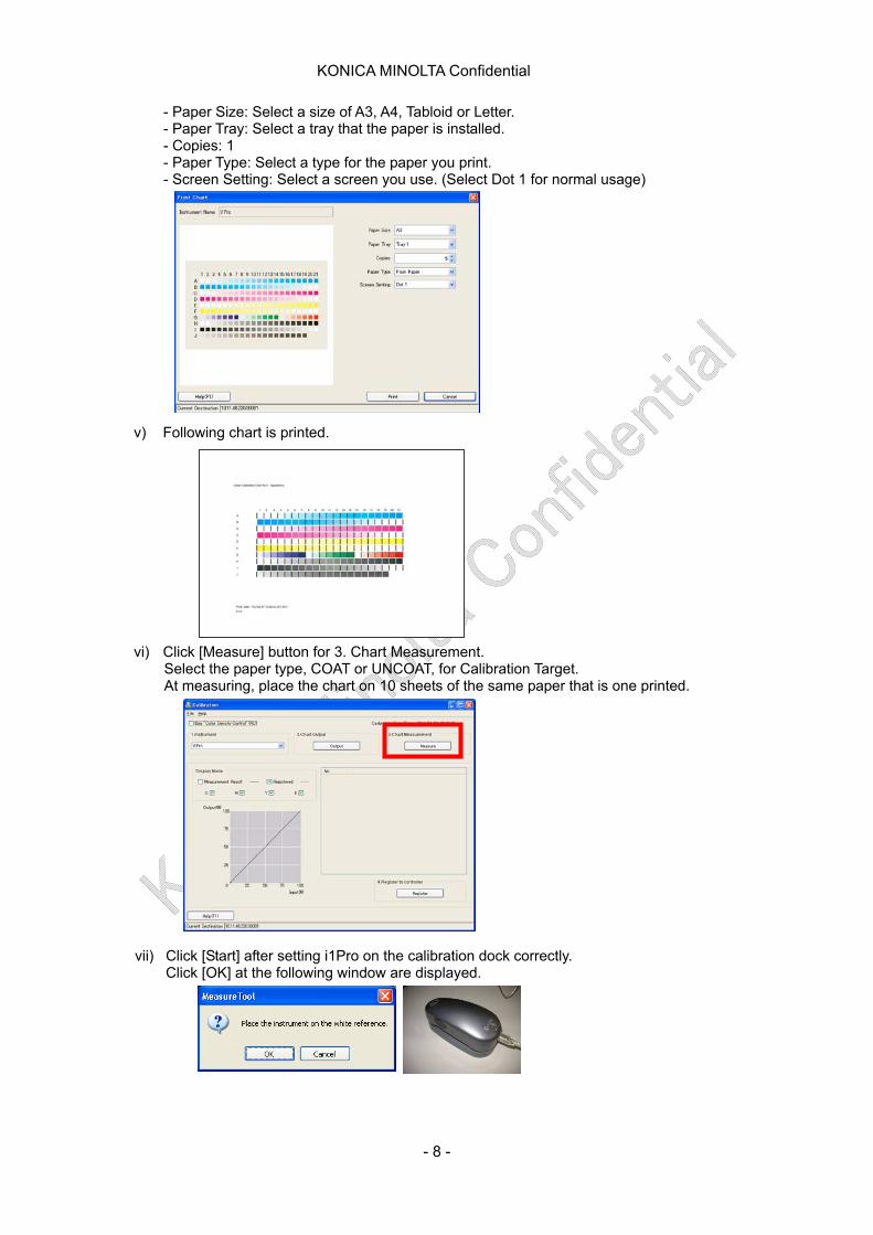
- Paper Size: Select a size of A3, A4, Tabloid or Letter. - Paper Tray: Select a tray that the paper is installed. - Copies: 1 - Paper Type: Select a type for the paper you print. - Screen Setting: Select a screen you use. (Select Dot 1 for normal usage)
v) Following chart is printed.
vi) Click [Measure] button for 3. Chart Measurement. Select the paper type, COAT or UNCOAT, for Calibration Target. At measuring, place the chart on 10 sheets of the same paper that is one printed.
vii) Click [Start] after setting i1Pro on the calibration dock correctly. Click [OK] at the following window are displayed.
- 8 -
KONICA MINOLTA Confidential
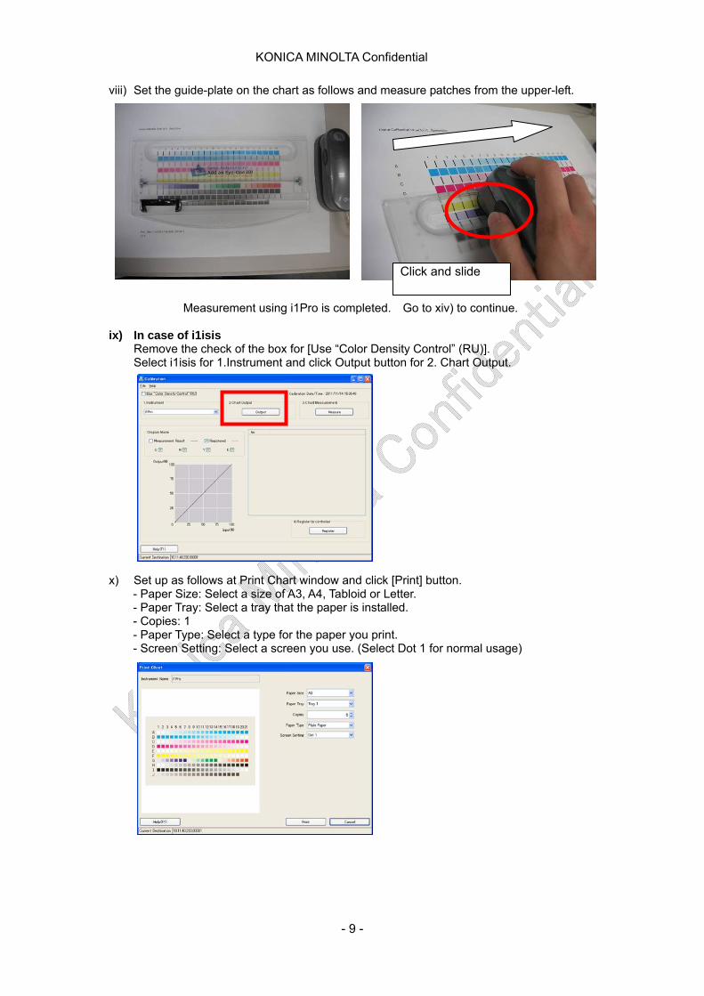
viii) Set the guide-plate on the chart as follows and measure patches from the upper-left. Measurement using i1Pro is completed. Go to xiv) to continue.
ix) In case of i1isis Remove the check of the box for [Use “Color Density Control” (RU)]. Select i1isis for 1.Instrument and click Output button for 2. Chart Output.
Click and slide
x) Set up as follows at Print Chart window and click [Print] button. - Paper Size: Select a size of A3, A4, Tabloid or Letter. - Paper Tray: Select a tray that the paper is installed. - Copies: 1 - Paper Type: Select a type for the paper you print. - Screen Setting: Select a screen you use. (Select Dot 1 for normal usage)
- 9 -

KONICA MINOLTA Confidential
xi) Following chart is printed xii) Click [Measure] button for 3. Chart Measurement.
Use scissors to cut a chart on dotted line.
xiii) Insert the chart in the direction of an arrow.
Measurement using i1iSis is completed. Go to xiv) to continue.
- 10 -
KONICA MINOLTA Confidential
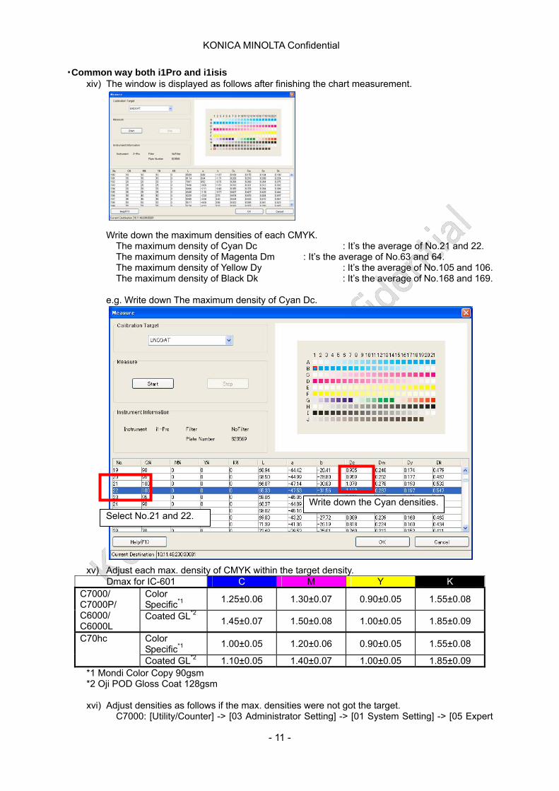
・Common way both i1Pro and i1isis xiv) The window is displayed as follows after finishing the chart measurement.
Write down the maximum densities of each CMYK. The maximum density of Cyan Dc : It’s the average of No.21 and 22. The maximum density of Magenta Dm : It’s the average of No.63 and 64. The maximum density of Yellow Dy : It’s the average of No.105 and 106. The maximum density of Black Dk : It’s the average of No.168 and 169.
e.g. Write down The maximum density of Cyan Dc.
Select No.21 and 22.
Write down the Cyan densities.
xv) Adjust each max. density of CMYK within the target density. Dmax for IC-601 C M Y K
Color Specific*1
1.25±0.06 1.30±0.07 0.90±0.05 1.55±0.08 C7000/ C7000P/ C6000/ C6000L
Coated GL*2 1.45±0.07 1.50±0.08 1.00±0.05 1.85±0.09
Color Specific*1
1.00±0.05 1.20±0.06 0.90±0.05 1.55±0.08 C70hc
Coated GL*2 1.10±0.05 1.40±0.07 1.00±0.05 1.85±0.09 *1 Mondi Color Copy 90gsm *2 Oji POD Gloss Coat 128gsm
xvi) Adjust densities as follows if the max. densities were not got the target.
C7000: [Utility/Counter] -> [03 Administrator Setting] -> [01 System Setting] -> [05 Expert
- 11 -
KONICA MINOLTA Confidential
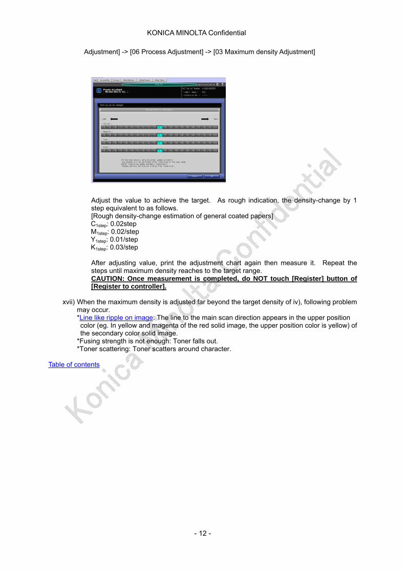
Adjustment] -> [06 Process Adjustment] -> [03 Maximum density Adjustment]
Adjust the value to achieve the target. As rough indication, the density-change by 1 step equivalent to as follows. [Rough density-change estimation of general coated papers] C1step: 0.02step M1step: 0.02/step Y1step: 0.01/step K1step: 0.03/step
After adjusting value, print the adjustment chart again then measure it. Repeat the steps until maximum density reaches to the target range. CAUTION: Once measurement is completed, do NOT touch [Register] button of [Register to controller].
xvii) When the maximum density is adjusted far beyond the target density of iv), following problem
may occur. *Line like ripple on image: The line to the main scan direction appears in the upper position color (eg. In yellow and magenta of the red solid image, the upper position color is yellow) of the secondary color solid image.
*Fusing strength is not enough: Toner falls out. *Toner scattering: Toner scatters around character.
Table of contents
- 12 -

KONICA MINOLTA Confidential
<IC-306 connected machine > i) In case of Fiery Command Work Station 5 (CWS5):
Start CWS5 and login to a Fiery controller.
ii) Click [Calibrate] button.
iii) Select [Expert].
iv) Click [Print…] button of [3.Generate Measurement Page] after selecting [1.Select Measurement Method] and [2. Check Print Settings]
- 13 -
KONICA MINOLTA Confidential
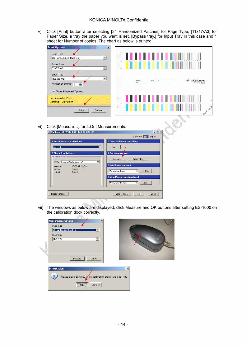
v) Click [Print] button after selecting [34 Randomized Patches] for Page Type, [11x17/A3] for Paper Size, a tray the paper you want is set, [Bypass tray.] for Input Tray in this case and 1 sheet for Number of copies. The chart as below is printed.
vi) Click [Measure…] for 4.Get Measurements.
vii) The windows as below are displayed, click Measure and OK buttons after setting ES-1000 on the calibration dock correctly.
- 14 -
KONICA MINOLTA Confidential
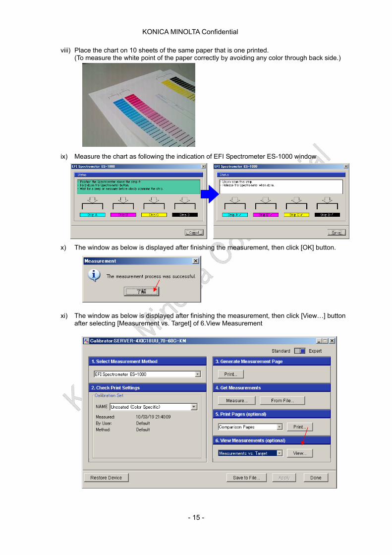
viii) Place the chart on 10 sheets of the same paper that is one printed. (To measure the white point of the paper correctly by avoiding any color through back side.)
ix) Measure the chart as following the indication of EFI Spectrometer ES-1000 window
x) The window as below is displayed after finishing the measurement, then click [OK] button.
xi) The window as below is displayed after finishing the measurement, then click [View…] button after selecting [Measurement vs. Target] of 6.View Measurement
- 15 -
KONICA MINOLTA Confidential
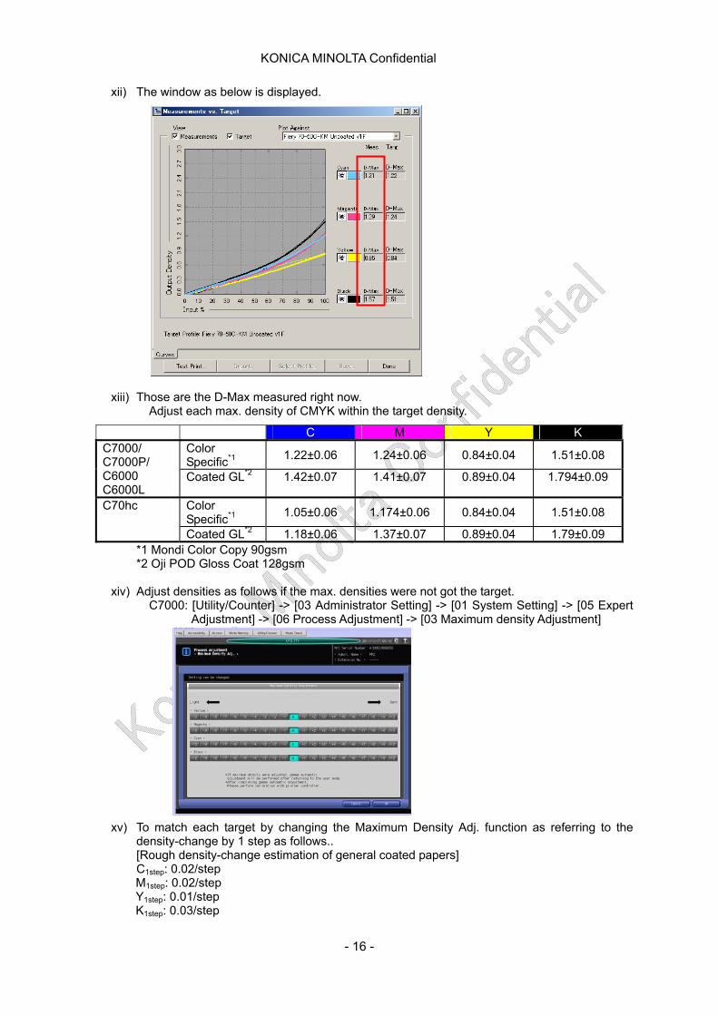
xii) The window as below is displayed.
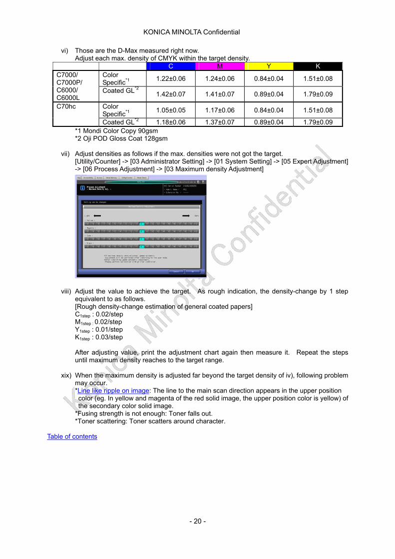
xiii) Those are the D-Max measured right now. Adjust each max. density of CMYK within the target density.
*1 Mondi Color Copy 90gsm
C M Y K Color Specific*1
1.22±0.06 1.24±0.06 0.84±0.04 1.51±0.08 C7000/ C7000P/ C6000 C6000L
Coated GL*2 1.42±0.07 1.41±0.07 0.89±0.04 1.794±0.09
Color Specific*1
1.05±0.06 1.174±0.06 0.84±0.04 1.51±0.08 C70hc
Coated GL*2 1.18±0.06 1.37±0.07 0.89±0.04 1.79±0.09
*2 Oji POD Gloss Coat 128gsm
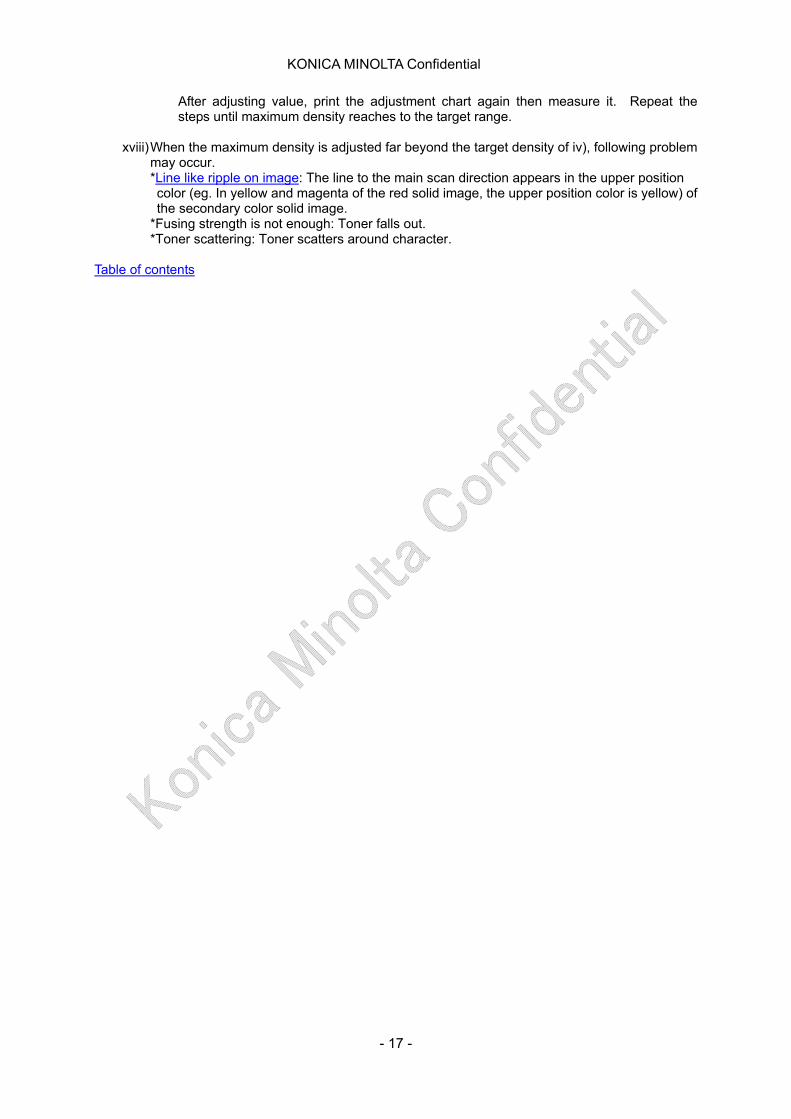
xiv) Adjust densities as follows if the max. densities were not got the target. C7000: [Utility/Counter] -> [03 Administrator Setting] -> [01 System Setting] -> [05 Expert
Adjustment] -> [06 Process Adjustment] -> [03 Maximum density Adjustment]
xv) To match each target by changing the Maximum Density Adj. function as referring to the density-change by 1 step as follows.. [Rough density-change estimation of general coated papers] C1step: 0.02/step M1step: 0.02/step Y1step: 0.01/step K1step: 0.03/step
- 16 -
KONICA MINOLTA Confidential
After adjusting value, print the adjustment chart again then measure it. Repeat the steps until maximum density reaches to the target range.
xviii) When the maximum density is adjusted far beyond the target density of iv), following problem
may occur. *Line like ripple on image: The line to the main scan direction appears in the upper position color (eg. In yellow and magenta of the red solid image, the upper position color is yellow) of the secondary color solid image.
*Fusing strength is not enough: Toner falls out. *Toner scattering: Toner scatters around character.
Table of contents
- 17 -
KONICA MINOLTA Confidential
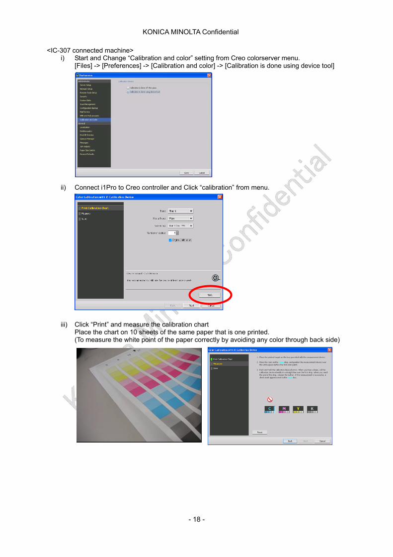
<IC-307 connected machine> i) Start and Change “Calibration and color” setting from Creo colorserver menu.
[Files] -> [Preferences] -> [Calibration and color] -> [Calibration is done using device tool]
ii) Connect i1Pro to Creo controller and Click “calibration” from menu.
iii) Click “Print” and measure the calibration chart Place the chart on 10 sheets of the same paper that is one printed. (To measure the white point of the paper correctly by avoiding any color through back side)
- 18 -
KONICA MINOLTA Confidential
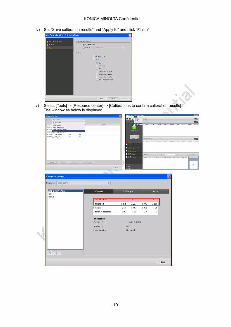
iv) Set “Save calibration results” and “Apply to” and click “Finish”
v) Select [Tools] -> [Resource center] -> [Calibrations to confirm calibration results] The window as below is displayed.
- 19 -
KONICA MINOLTA Confidential
vi) Those are the D-Max measured right now. Adjust each max. density of CMYK within the target density.
C M Y K Color Specific*1
1.22±0.06 1.24±0.06 0.84±0.04 1.51±0.08 C7000/ C7000P/ C6000/ C6000L
Coated GL*2 1.42±0.07 1.41±0.07 0.89±0.04 1.79±0.09
Color Specific*1
1.05±0.05 1.17±0.06 0.84±0.04 1.51±0.08 C70hc
Coated GL*2 1.18±0.06 1.37±0.07 0.89±0.04 1.79±0.09 *1 Mondi Color Copy 90gsm *2 Oji POD Gloss Coat 128gsm
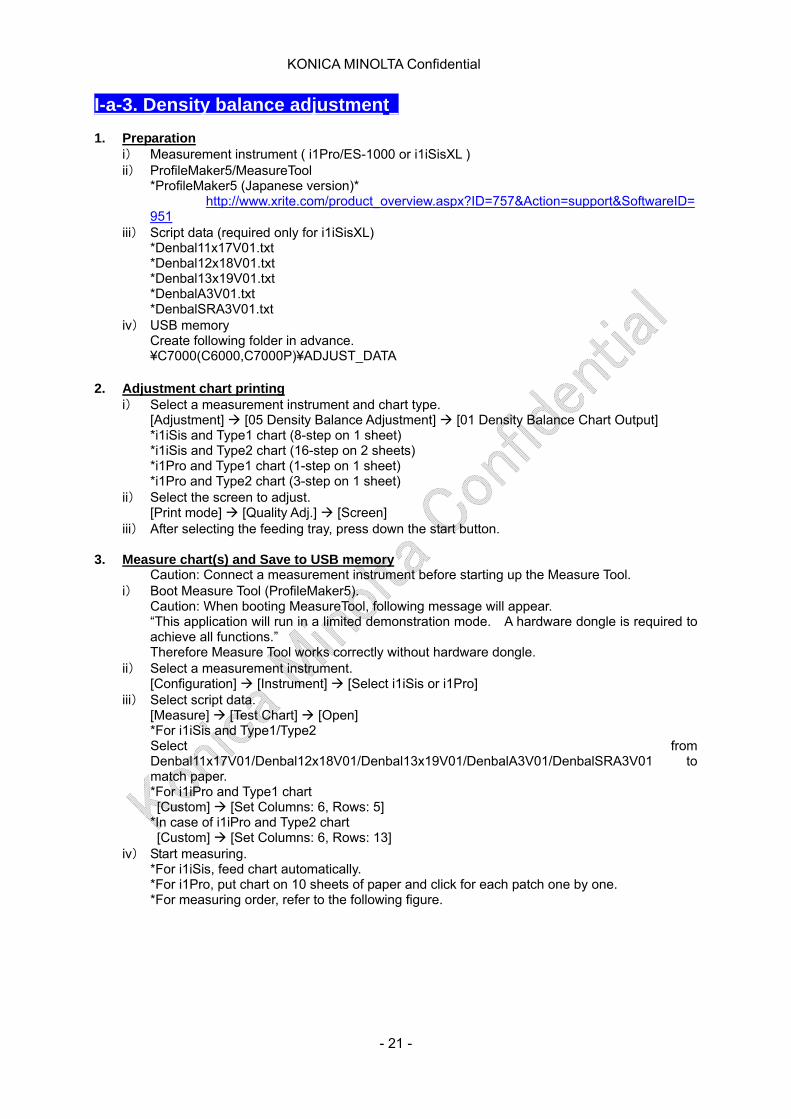
vii) Adjust densities as follows if the max. densities were not got the target.
[Utility/Counter] -> [03 Administrator Setting] -> [01 System Setting] -> [05 Expert Adjustment] -> [06 Process Adjustment] -> [03 Maximum density Adjustment]
viii) Adjust the value to achieve the target. As rough indication, the density-change by 1 step equivalent to as follows. [Rough density-change estimation of general coated papers] C1step : 0.02/step M1step : 0.02/step Y1step : 0.01/step K1step : 0.03/step After adjusting value, print the adjustment chart again then measure it. Repeat the steps until maximum density reaches to the target range.
xix) When the maximum density is adjusted far beyond the target density of iv), following problem
may occur. *Line like ripple on image: The line to the main scan direction appears in the upper position color (eg. In yellow and magenta of the red solid image, the upper position color is yellow) of the secondary color solid image.
*Fusing strength is not enough: Toner falls out. *Toner scattering: Toner scatters around character.
Table of contents
- 20 -
KONICA MINOLTA Confidential
I-a-3. Density balance adjustment 1. Preparation
i) Measurement instrument ( i1Pro/ES-1000 or i1iSisXL ) ii) ProfileMaker5/MeasureTool
*ProfileMaker5 (Japanese version)* http://www.xrite.com/product_overview.aspx?ID=757&Action=support&SoftwareID=951
iii) Script data (required only for i1iSisXL) *Denbal11x17V01.txt *Denbal12x18V01.txt *Denbal13x19V01.txt *DenbalA3V01.txt *DenbalSRA3V01.txt
iv) USB memory Create following folder in advance. ¥C7000(C6000,C7000P)¥ADJUST_DATA
2. Adjustment chart printing
i) Select a measurement instrument and chart type. [Adjustment] [05 Density Balance Adjustment] [01 Density Balance Chart Output] *i1iSis and Type1 chart (8-step on 1 sheet) *i1iSis and Type2 chart (16-step on 2 sheets) *i1Pro and Type1 chart (1-step on 1 sheet) *i1Pro and Type2 chart (3-step on 1 sheet)
ii) Select the screen to adjust. [Print mode] [Quality Adj.] [Screen]
iii) After selecting the feeding tray, press down the start button. 3. Measure chart(s) and Save to USB memory
Caution: Connect a measurement instrument before starting up the Measure Tool. i) Boot Measure Tool (ProfileMaker5).
Caution: When booting MeasureTool, following message will appear. “This application will run in a limited demonstration mode. A hardware dongle is required to achieve all functions.” Therefore Measure Tool works correctly without hardware dongle.
ii) Select a measurement instrument. [Configuration] [Instrument] [Select i1iSis or i1Pro]
iii) Select script data. [Measure] [Test Chart] [Open] *For i1iSis and Type1/Type2 Select from Denbal11x17V01/Denbal12x18V01/Denbal13x19V01/DenbalA3V01/DenbalSRA3V01 to match paper. *For i1iPro and Type1 chart [Custom] [Set Columns: 6, Rows: 5] *In case of i1iPro and Type2 chart [Custom] [Set Columns: 6, Rows: 13]
iv) Start measuring. *For i1iSis, feed chart automatically. *For i1Pro, put chart on 10 sheets of paper and click for each patch one by one. *For measuring order, refer to the following figure.
- 21 -

KONICA MINOLTA Confidential
<i1Pro/Type 1> <i1Pro/Type 2>
v) Finish measuring.
[Close] [Export Lab] vi) Based on the following naming rule [A] [B], save the data at
¥C7000(C6000/C7000P)¥ADJUST_DATA in USB memory. *Naming rule [A]: (14 characters of identifying information printed on the chart)_(up to 21 characters of arbitrary information) Example: 0051015011A573_i1iSisT1_2010_0628.txt *Naming rule [B]: Characters of user-customized information must be the same for both charts when i1iSis and Type 2 chart is used. Example: 0051015011A573_i1iSisT2_2010_0628.txt
10510150219D8E_i1iSisT2_2010_0628.txt 4. Register colorimetric data to printing engine
Caution: Don’t connect USB memory before indicated. i) Register the colorimetric data.
[Adjustment] [05 Density Balance Adjustment] [02 Density Balance Data Reg/Del] ii) Select the desired number of row from the 10 on the list. iii) Press [Measured data load] iv) Connect USB memory and Press [OK]. v) Select the file name of the data to be registered and Press [OK]. vi) *When replacing data, press [Overwrite].
*When combining selected data, press [Combination]. *When stopping overwrite or combination, press [Cancel]. *When small adjustment is necessary, start from [Manual Setting].
Table of contents
- 22 -
KONICA MINOLTA Confidential
I-a-4. Register paper category 1. Preparation
i) Measurement instrument ( i1Pro/ES-1000 or i1iSisXL ) ii) ProfileMaker5/MeasureTool
*ProfileMaker5 (Japanese version)* http://www.xrite.com/product_overview.aspx?ID=757&Action=support&SoftwareID=951
iii) Script data (required only for i1iSisXL) *OutdensenA3V01_S1Cut.txt *OutdensenA4V01_S1Cut.txt *OutdensenB5V01_S1Cut.txt
iv) USB memory Create following folder in advance. ¥C7000(C6000/C7000P)¥ADJUST_DATA
2. Adjustment chart printing i) Select a measurement instrument and chart type.
[Adjustment] [06 Color Density Control] [03 Register Paper Category] ii) Select the category name No. on the Paper Category List. iii) Press [Print mode”] and enter the desired name. iv) Select the screen type.
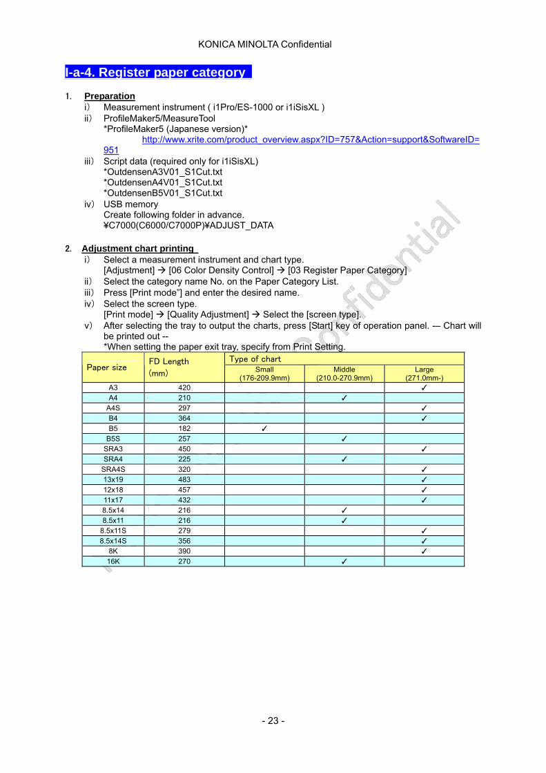
[Print mode] [Quality Adjustment] Select the [screen type]. v) After selecting the tray to output the charts, press [Start] key of operation panel. -– Chart will
be printed out -- *When setting the paper exit tray, specify from Print Setting.
Type of chart Paper size
FD Length
(mm) Small (176-209.9mm)
Middle (210.0-270.9mm)
Large (271.0mm-)
A3 420 ✓ A4 210 ✓
A4S 297 ✓ B4 364 ✓ B5 182 ✓
B5S 257 ✓ SRA3 450 ✓ SRA4 225 ✓
SRA4S 320 ✓ 13x19 483 ✓ 12x18 457 ✓ 11x17 432 ✓ 8.5x14 216 ✓ 8.5x11 216 ✓
8.5x11S 279 ✓ 8.5x14S 356 ✓
8K 390 ✓ 16K 270 ✓
- 23 -

KONICA MINOLTA Confidential
3. Measure chart(s) and Save to USB memory Caution: Connect a measurement instrument before starting up the Measure Tool.
i) Boot Measure Tool (ProfileMaker5). Caution: When booting MeasureTool, following message will appear. "This application will run in a limited demonstration mode. A hardware dongle is required to achieve all functions." However Measure Tool works correctly without hardware dongle.
ii) Select a measurement instrument. [Configuration] [Instrument] Select [i1iSis] or [i1Pro]
iii) Select script data. [Measure] [Testchart] [Open]
*For i1iSis and Large chart (3 sheets), select OutdensenA3V01_S1Cut.txt *For i1iPro and Middle chart (4 sheets), select OutdensenA4V01_S1Cut.txt *For i1iPro and Small chart (6 sheets), select OutdensenB5V01_S1Cut.txt
*For i1Pro and Large chart (3 sheets) Custom set Columns: 4 and Rows: 11 *For i1Pro and Middle chart (4 sheets) Custom set Columns: 4 and Rows: 8 *For i1Pro and Small chart (6 sheets) Custom set Columns: 4 and Rows: 6 iv) Start measuring.
*For i1iSis, cut off the left edge of the chart (10mm from black diamond mark), then scan chart automatically and measure chart read one by one. For details, refer to the figure below. Caution: When finishing each measurement, close and save the colorimetric data one by one, even a message will appear to prompt you to load nex chart. *For i1Pro, put chart on the 10 sheets of paper used for the chart and click on each patche one by one. *For measuring order, refer to the following figure.
<Large chart> <Middle chart> <Small chart>
v) inish measuring
[Close] [Export Lab] vi) Name as 4 characters of identifying information printed on the chart at
¥C7000(C6000/C7000P)¥ADJUST_DATA in USB memory. *Example: 0231.txt, 0232.txt, 0233.txt
- 24 -
KONICA MINOLTA Confidential
4. Register colorimetric data to printing engine Caution: Don’t connect USB memory before indicated. i) Register the colorimetric data.
[Adjustment] [05 Color Density Control] [03 Register Paper Category] ii) Select corresponding row on Paper Category List to the printed chart. iii) Press [Mesured data load]. iv) Connect USB memory with main body and press [OK]. v) Select the file name of the data to be registered and press [OK].
Table of contents
- 25 -
KONICA MINOLTA Confidential
I-a-5. Printer controller calibration <Printer controller>
IC-601 IC-306 IC-307
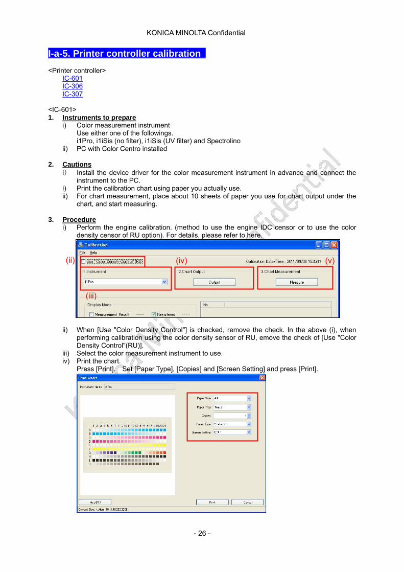
<IC-601> 1. Instruments to prepare
i) Color measurement instrument Use either one of the followings. i1Pro, i1iSis (no filter), i1iSis (UV filter) and Spectrolino
ii) PC with Color Centro installed 2. Cautions
i) Install the device driver for the color measurement instrument in advance and connect the instrument to the PC.
i) Print the calibration chart using paper you actually use. ii) For chart measurement, place about 10 sheets of paper you use for chart output under the
chart, and start measuring. 3. Procedure
i) Perform the engine calibration. (method to use the engine IDC censor or to use the color density censor of RU option). For details, please refer to here.
(ii) (v) (iv)
(iii)
ii) When [Use "Color Density Control"] is checked, remove the check. In the above (i), when performing calibration using the color density sensor of RU, emove the check of [Use "Color Density Control"(RU)].
iii) Select the color measurement instrument to use. iv) Print the chart.
Press [Print]. Set [Paper Type], [Copies] and [Screen Setting] and press [Print].
- 26 -

KONICA MINOLTA Confidential
v) Measure the chart. Click [Measure] and select the calibration target. vi) Click [Start] and measure as following the screen instruction. When the measurement is
completed, the measurement result is displayed in a list and the patch is also displayed in color on the preview window.
vii) Press [OK].
viii) The measurement data is displayed on a list of the calibration screen. ix) Using the same chart, measure again (from Step (v) to (vii)).
Considering the instrument and its measurement fluctuation, it is recommended to measure several times.
x) Multiple measurement results is recorded on the list of the calibration screen. (Up to 10)
(xiii)
(xi) (x)
xi) Input the check mark to the [Measurement Result] of Display Mode and check the selected measurement result. By inputting the check mark to [Registered], the registered contents also can be viewed.
xii) Comparing the multiple measurement results on a list, select the most standard measurement result as calibration data.
xiii) Select the selected measurement result and register to the controller. xiv) Press [OK].
Table of contents
- 27 -
KONICA MINOLTA Confidential
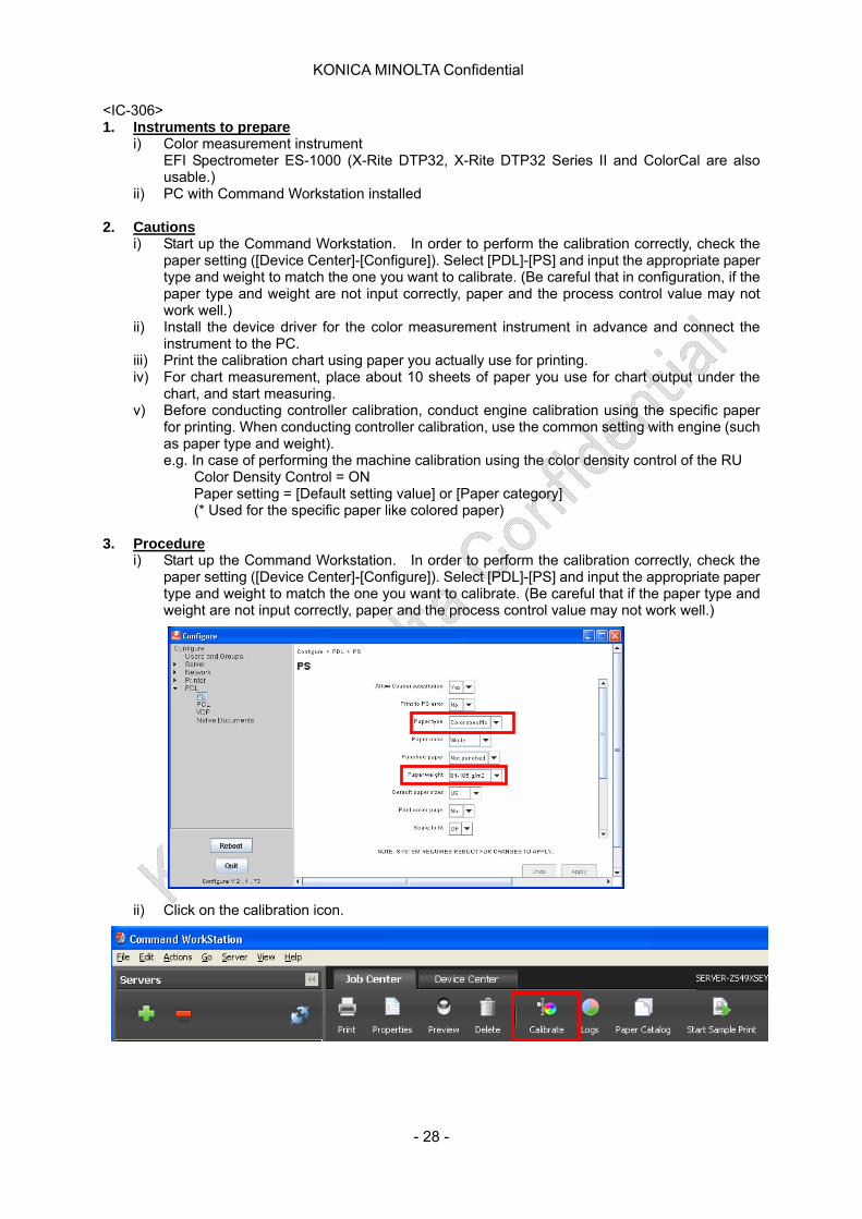
<IC-306> 1. Instruments to prepare
i) Color measurement instrument EFI Spectrometer ES-1000 (X-Rite DTP32, X-Rite DTP32 Series II and ColorCal are also usable.)
ii) PC with Command Workstation installed 2. Cautions
i) Start up the Command Workstation. In order to perform the calibration correctly, check the paper setting ([Device Center]-[Configure]). Select [PDL]-[PS] and input the appropriate paper type and weight to match the one you want to calibrate. (Be careful that in configuration, if the paper type and weight are not input correctly, paper and the process control value may not work well.)
ii) Install the device driver for the color measurement instrument in advance and connect the instrument to the PC.
iii) Print the calibration chart using paper you actually use for printing. iv) For chart measurement, place about 10 sheets of paper you use for chart output under the
chart, and start measuring. v) Before conducting controller calibration, conduct engine calibration using the specific paper
for printing. When conducting controller calibration, use the common setting with engine (such as paper type and weight). e.g. In case of performing the machine calibration using the color density control of the RU
Color Density Control = ON Paper setting = [Default setting value] or [Paper category] (* Used for the specific paper like colored paper)
3. Procedure
i) Start up the Command Workstation. In order to perform the calibration correctly, check the paper setting ([Device Center]-[Configure]). Select [PDL]-[PS] and input the appropriate paper type and weight to match the one you want to calibrate. (Be careful that if the paper type and weight are not input correctly, paper and the process control value may not work well.)
ii) Click on the calibration icon.
- 28 -
KONICA MINOLTA Confidential
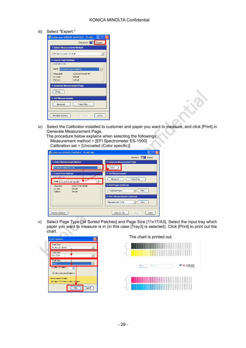
iii) Select "Expert."
iv) Select the Calibrator installed to customer and paper you want to measure, and click [Print] in
Generate Measurement Page. The procedure below explains when selecting the followings.
Measurement method = [EFI Spectrometer ES-1000] Calibration set = [Uncoated (Color specific)]
v) Select Page Type [34 Sorted Patches] and Page Size [11x17/A3]. Select the input tray which paper you want to measure is in (in this case [Tray3] is selected). Click [Print] to print out the chart.
The chart is printed out.
- 29 -

KONICA MINOLTA Confidential
vi) Click [Measure] from [4. Get Measurements].
vii) * From here, ES1000 operation starts. Following the screen instruction, measure the chart printed in Step 5 for each CMYK using ES1000.
Here is the button described in screen instruction.
ES-1000
viii) Click on [Apply]. (The measurement result can be checked by clicking the [View] button in [6.
View Measurements (optional)]. Table of contents
- 30 -
KONICA MINOLTA Confidential
<IC-307> 1. Instruments to prepare
i) When using Off-the-grass calibration Engine with scanner
ii) When performing calibration with spectrophotometer i1Pro or i1iSis
2. Cautions
i) Print the calibration chart on paper usually using for print job. If using the different paper, the correct result does not come out.
3. Procedure <How to perform the Off-the-Glass calibration>
i) Select [System Setting] from [File] menu and select [Calibration is done off-the-glass] under [Calibration Device].
ii) Select [Calibration] from [Tool] menu. iii) Select the object tray from [Tray] list. The default is [Tray1].
Calibration chart can be printed on the arbitrary paper whose size is equal to or bigger than A4 or letter.
iv) Select the paper type (like Coated) in the [Media Type] list. Job is printed on the paper type that is defined by printer.
v) Select the screen method in the [Screening] list. In order to get the best result, set the screening type to the one used for print job.
vi) Input the number of copy in the [Number of copies] box. vii) Click [Print]. Calibration chart is printed. viii) Click [Next]. ix) Place the printer chart and scanner chart on the platen side by side, and follow the instruction
of the calibration wizard. x) When the last chart is measured correctly, click [Next] and apply calibration to the target
paper type. xi) Select the [All Media Types] check box and apply calibration to all the papers, or select
[Select] check box and select the target paper type. xii) Click [Finish].
<How to perform calibration with spectrophotometer>
i) Select [System Setting] from [File] menu and select [Calibration is done using device tool] under [Calibration Device].
ii) Connect the cable for Eye-One spectrophotometer to the IC-304 print controller USB port, and connect the other end to the Eye-One spectrometer.
iii) Place the spectrophotometer on the plate and calibrate the Eye-One spectrophotometer. iv) Set paper which is used for print job. v) Select [Calibration] from the [Tools] menu. vi) Select the object tray from [Tray] list. The default is [Tray1]. Calibration chart can be printed
on the arbitrary paper whose size is equal to or bigger than A4 or letter. vii) Select the paper type (like Coated) in the [Media Type] list. Job is printed on the paper type
that is defined by printer. viii) Select the screen method in the [Screening] list. In order to get the best result, set the
screening type to the one used for print job. ix) Input the number of copy in the [Number of copies] box. x) Click [Print]. Calibration chart is printed. xi) Click [Next]. xii) Place the calibration chart on the flat surface and scan by Eye-One spectrophotometer as
follows. ※ Keep pushing the button at the side of the spectrophotometer and align the head to
the Cyan's allow tip. ※ The allow is located at the Cyan colum in the calibration chart and its edge
intersects with the dot-line. ※ Slide the spectrophotometer along the Cyan colum and wait until it beeps. ※ Check mark is displayed on the Cyan icon in the color calibration window.
- 31 -
KONICA MINOLTA Confidential
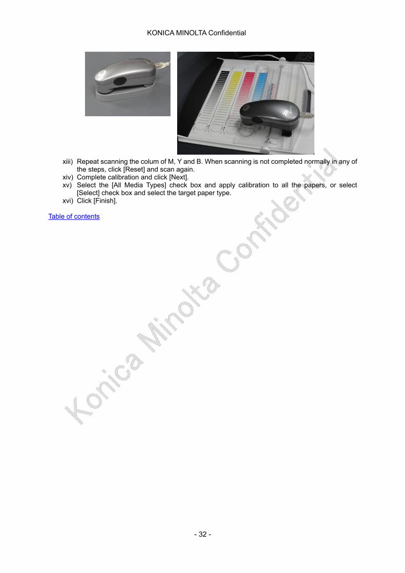
xiii) Repeat scanning the colum of M, Y and B. When scanning is not completed normally in any of the steps, click [Reset] and scan again.
xiv) Complete calibration and click [Next]. xv) Select the [All Media Types] check box and apply calibration to all the papers, or select
[Select] check box and select the target paper type. xvi) Click [Finish].
Table of contents
- 32 -
KONICA MINOLTA Confidential
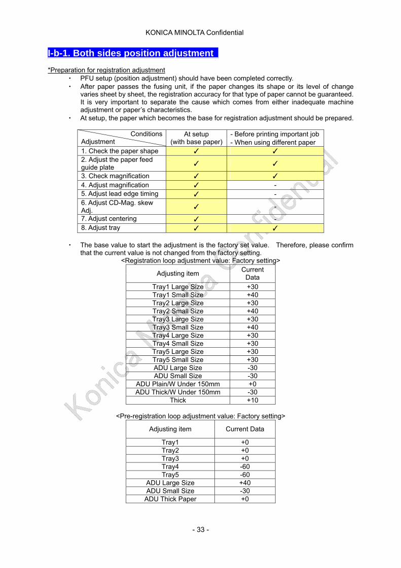
I-b-1. Both sides position adjustment *Preparation for registration adjustment
・ PFU setup (position adjustment) should have been completed correctly. ・ After paper passes the fusing unit, if the paper changes its shape or its level of change
varies sheet by sheet, the registration accuracy for that type of paper cannot be guaranteed. It is very important to separate the cause which comes from either inadequate machine adjustment or paper’s characteristics.
・ At setup, the paper which becomes the base for registration adjustment should be prepared.
- Before printing important job Conditions Adjustment
At setup (with base paper) - When using different paper
1. Check the paper shape ✓ ✓ 2. Adjust the paper feed guide plate
✓ ✓
3. Check magnification ✓ ✓ 4. Adjust magnification ✓ - 5. Adjust lead edge timing ✓ - 6. Adjust CD-Mag. skew Adj.
✓ -
7. Adjust centering ✓ - 8. Adjust tray ✓ ✓
・ The base value to start the adjustment is the factory set value. Therefore, please confirm
that the current value is not changed from the factory setting. <Registration loop adjustment value: Factory setting>
Adjusting item Current
Data
Tray1 Large Size +30 Tray1 Small Size +40 Tray2 Large Size +30 Tray2 Small Size +40 Tray3 Large Size +30 Tray3 Small Size +40 Tray4 Large Size +30 Tray4 Small Size +30 Tray5 Large Size +30 Tray5 Small Size +30 ADU Large Size -30 ADU Small Size -30
ADU Plain/W Under 150mm +0 ADU Thick/W Under 150mm -30
Thick +10
<Pre-registration loop adjustment value: Factory setting>
Adjusting item Current Data
Tray1 +0 Tray2 +0 Tray3 +0 Tray4 -60 Tray5 -60
ADU Large Size +40 ADU Small Size -30
ADU Thick Paper +0
- 33 -
KONICA MINOLTA Confidential
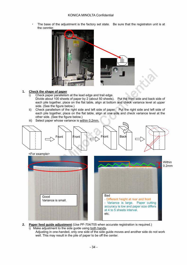
・ The base of the adjustment is the factory set state. Be sure that the registraton unit is at the cennter.
1. Check the shape of paper
i) Check paper parallelism at the lead edge and trail edge. Divide about 100 sheets of paper by 2 (about 50 sheets). Put the front side and back side of each pile together, place on the flat table, align at bottom and check variance level at upper side. (See the figure below.)
ii) Check parallelism of the right side and left side of paper. Put the right side and left side of each pile together, place on the flat table, align at one side and check variance level at the other side. (See the figure below.)
iii) Select paper whose variance is within 0.2mm.
Front Back Front Front
<For example>
Good Variance is small.
Within 0.2mm
Bad - Different height at rear and front - Variance is large. Paper cutting accuracy is low and paper size differs at 4 to 5 sheets interval. etc.
2. Paper feed guide adjustment (Use PF-704/705 when ai) M
ccurate registration is required.) ake adjustment to the side guide using both hands. Adjusting in one-handed, only one side of the side guide moves and another side do not work
ell. This may result in the pile of paper to be off the center. w
- 34 -
KONICA MINOLTA Confidential
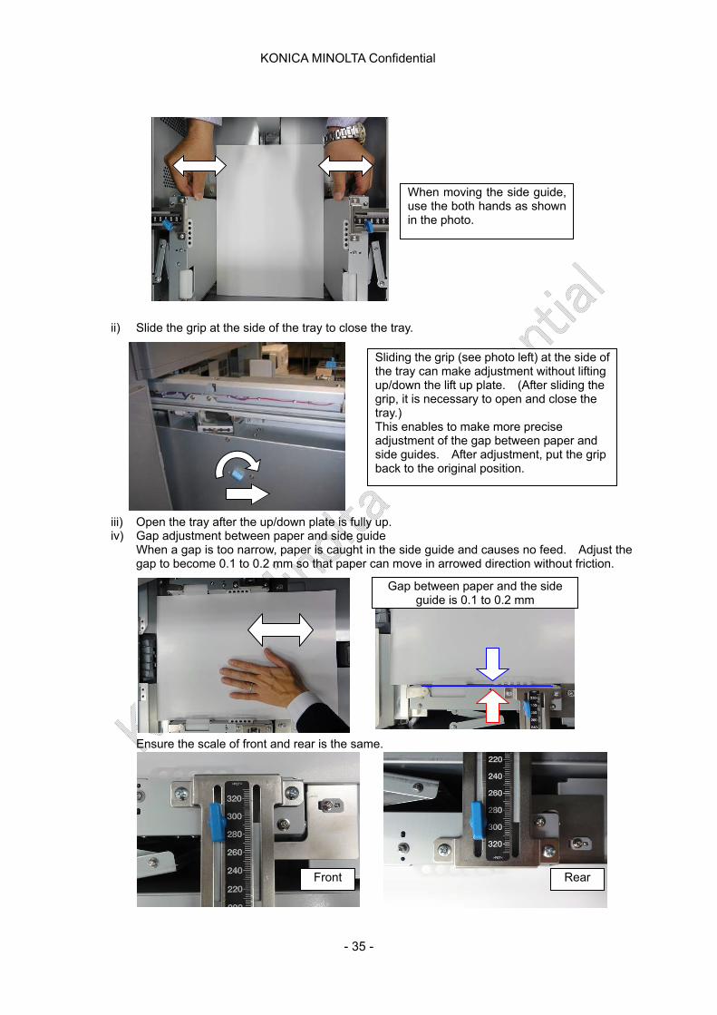
When moving the side guide, use the both hands as shown in the photo.
ii) se the tray.
iv)
e gap to become 0.1 to 0.2 mm so that paper can friction.
Ensure the scale of front and rear is the same.
Slide the grip at the side of the tray to clo
Sliding the grip (see photo left) at the side of the tray can make adjustment without lifting up/down the lift up plate. (After sliding thegrip, it
is necessary to open and close the
t, put the grip back to the original position.
tray.) This enables to make more precise adjustment of the gap between paper and side guides. After adjustmen
iii) Open the tray after the up/down plate is fully up.
Gap adjustment between paper and side guide When a gap is too narrow, paper is caught in the side guide and causes no feed. Adjust th
move in arrowed direction without
Gap side guide is 0.1 to 0.2 mm between paper and the
Front Rear
- 35 -
KONICA MINOLTA Confidential
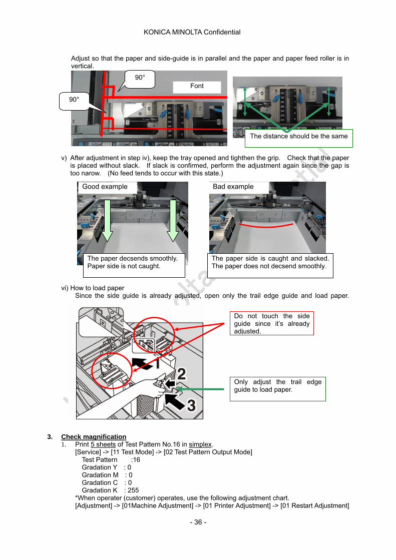
hat the paper and side-guide is in parallel and the paper and paper feed roller is in
the adjustment again since the gap is too naro ds to occur with this state.
vi) HSince the side guide is already adjusted, open only the trail edge guide and load paper.
Adjust so tvertical.
Font 90°
90°
v) After adjustment in step iv), keep the tray opened and tighthen the grip. Check that the paper is placed without slack. If slack is confirmed, perform
The distance should be the same
w. (No feed ten )
ow to load paper
3. Check magnification
1. Print 5 sheets of Test Pattern No.16 in simplex. [S Test Mode] -> [02 Test Pattern Output Mode]
6
[Adjustment] -> [01Machine Adjustment] -> [01 Printer Adjustment] -> [01 Restart Adjustment]
ervice] -> [11 Test Pattern :1Gradation Y : 0 Gradation M : 0 Gradation C : 0 Gradation K : 255
*When operater (customer) operates, use the following adjustment chart.
Do not touch the side guide since it’s already adjusted.
Only adjust the trail edge guide to load paper.
The paper decsends smoothly. Paper side is not caught.
Good example Bad example
The paper side is caught and slacked. The paper does not decsend smoothly.
- 36 -
KONICA MINOLTA Confidential
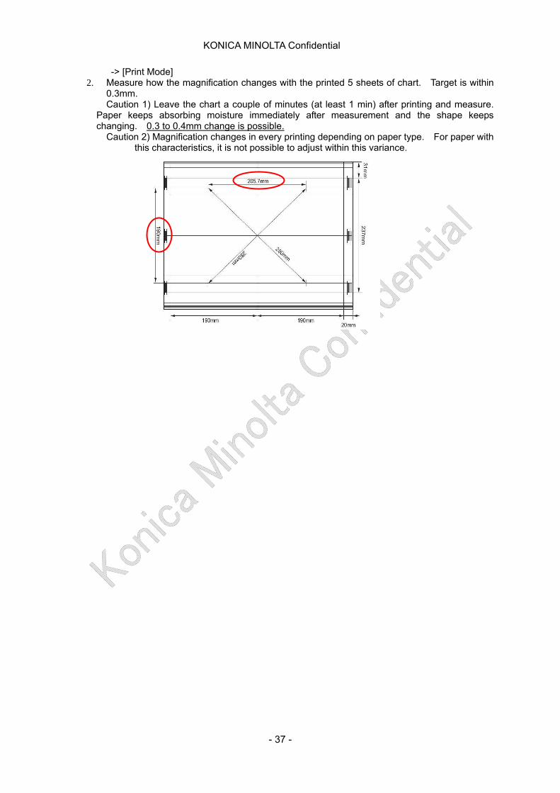
-> [Print Mode] 2. Measure how the magnification changes with the printed 5 sheets of chart. Target is within
ly after measurement and the shape keeps ch
0.3mm. Caution 1) Leave the chart a couple of minutes (at least 1 min) after printing and measure.
Paper keeps absorbing moisture immediateanging. 0.3 to 0.4mm change is possible.
n 2) Magnification changes in every printing depending on paper typCautio e. For paper with this characteristics, it is not possible to adjust within this variance.
- 37 -
KONICA MINOLTA Confidential
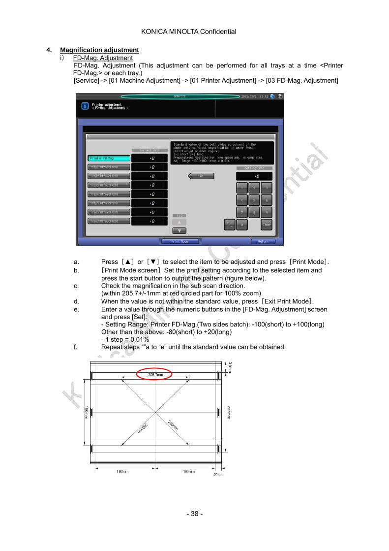
4. Magnification adjustment i) FD-Mag. Adjustment
FD-Mag. Adjustment (This adjustment can be performed for all trays at a time <Printer FD-Mag.> or each tray.) [Service] -> [01 Machine Adjustment] -> [01 Printer Adjustment] -> [03 FD-Mag. Adjustment] a. Press [▲] or [▼] to select the item to be adjusted and press [Print Mode]. b. [Print Mode screen] Set the print setting according to the selected item and
press the start button to output the pattern (figure below). c. Check the magnification in the sub scan direction.
(within 205.7+/-1mm at red circled part for 100% zoom) d. When the value is not within the standard value, press [Exit Print Mode]. e. Enter a value through the numeric buttons in the [FD-Mag. Adjustment] screen
and press [Set]. - Setting Range: Printer FD-Mag.(Two sides batch): -100(short) to +100(long) Other than the above: -80(short) to +20(long) - 1 step = 0.01%
f. Repeat steps “”a to “e” until the standard value can be obtained.
- 38 -
KONICA MINOLTA Confidential
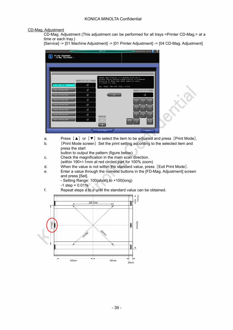
CD-Mag. Adjustment CD-Mag. Adjustment (This adjustment can be performed for all trays <Printer CD-Mag.> at a time or each tray.) [Service] -> [01 Machine Adjustment] -> [01 Printer Adjustment] -> [04 CD-Mag. Adjustment] a. Press [▲] or [▼] to select the item to be adjusted and press [Print Mode]. b. [Print Mode screen] Set the print setting according to the selected item and
press the start button to output the pattern (figure below).
c. Check the magnification in the main scan direction. (within 190+/-1mm at red circled part for 100% zoom)
d. When the value is not within the standard value, press [Exit Print Mode]. e. Enter a value through the numeric buttons in the [FD-Mag. Adjustment] screen
and press [Set]. - Setting Range: 100(short) to +100(long) -1 step = 0.01%
f. Repeat steps a to e until the standard value can be obtained.
- 39 -
KONICA MINOLTA Confidential
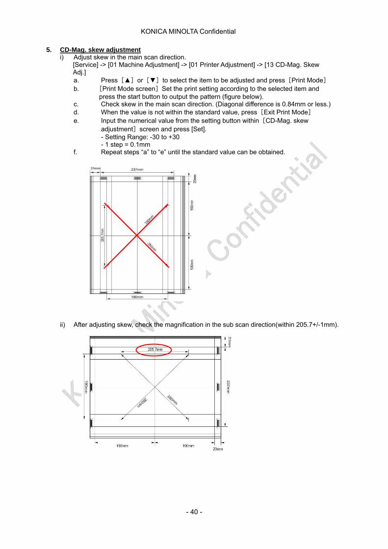
5. CD-Mag. skew adjustment i) Adjust skew in the main scan direction.
[Service] -> [01 Machine Adjustment] -> [01 Printer Adjustment] -> [13 CD-Mag. Skew Adj.] a. Press [▲] or [▼] to select the item to be adjusted and press [Print Mode] b. [Print Mode screen] Set the print setting according to the selected item and
press the start button to output the pattern (figure below). c. Check skew in the main scan direction. (Diagonal difference is 0.84mm or less.) d. When the value is not within the standard value, press [Exit Print Mode] e. Input the numerical value from the setting button within [CD-Mag. skew
adjustment] screen and press [Set]. - Setting Range: -30 to +30 - 1 step = 0.1mm
f. Repeat steps “a” to “e” until the standard value can be obtained.
ii) After adjusting skew, check the magnification in the sub scan direction(within 205.7+/-1mm).
- 40 -
KONICA MINOLTA Confidential
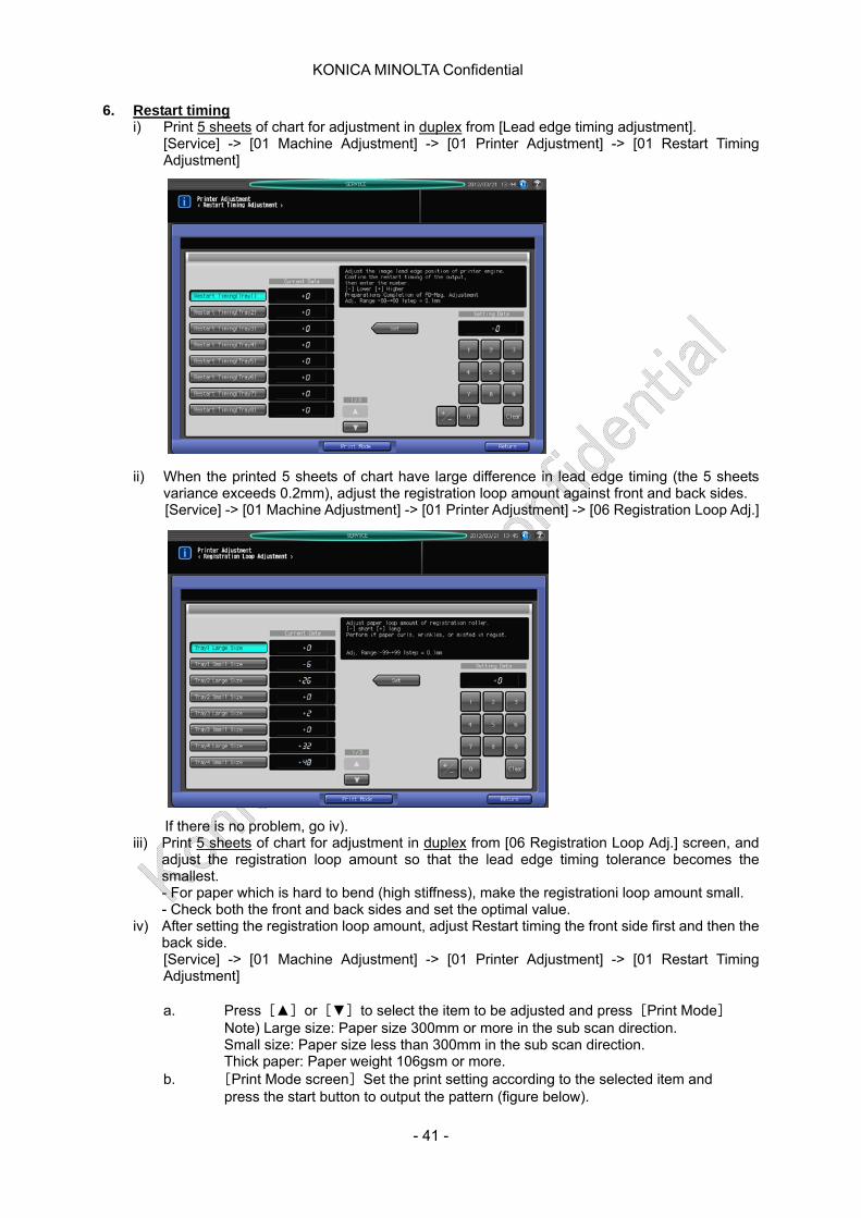
6. Restart timing i) Print 5 sheets of chart for adjustment in duplex from [Lead edge timing adjustment].
[Service] -> [01 Machine Adjustment] -> [01 Printer Adjustment] -> [01 Restart Timing Adjustment]
ii) When the printed 5 sheets of chart have large difference in lead edge timing (the 5 sheets variance exceeds 0.2mm), adjust the registration loop amount against front and back sides. [Service] -> [01 Machine Adjustment] -> [01 Printer Adjustment] -> [06 Registration Loop Adj.] If there is no problem, go iv).
iii) Print 5 sheets of chart for adjustment in duplex from [06 Registration Loop Adj.] screen, and adjust the registration loop amount so that the lead edge timing tolerance becomes the smallest. - For paper which is hard to bend (high stiffness), make the registrationi loop amount small. - Check both the front and back sides and set the optimal value.
iv) After setting the registration loop amount, adjust Restart timing the front side first and then the back side. [Service] -> [01 Machine Adjustment] -> [01 Printer Adjustment] -> [01 Restart Timing Adjustment] a. Press [▲] or [▼] to select the item to be adjusted and press [Print Mode]
Note) Large size: Paper size 300mm or more in the sub scan direction. Small size: Paper size less than 300mm in the sub scan direction. Thick paper: Paper weight 106gsm or more.
b. [Print Mode screen] Set the print setting according to the selected item and press the start button to output the pattern (figure below).
- 41 -
KONICA MINOLTA Confidential
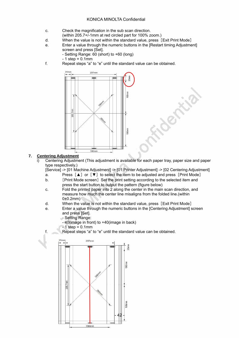
c. Check the magnification in the sub scan direction. (within 205.7+/-1mm at red circled part for 100% zoom.)
d. When the value is not within the standard value, press [Exit Print Mode] e. Enter a value through the numeric buttons in the [Restart timing Adjustment]
screen and press [Set]. - Setting Range: 60 (short) to +60 (long) - 1 step = 0.1mm
f. Repeat steps “a” to “e” until the standard value can be obtained.
7. Centering Adjustment
i) Centering Adjustment (This adjustment is available for each paper tray, paper size and paper type respectively.) [Service] -> [01 Machine Adjustment] -> [01 Printer Adjustment] -> [02 Centering Adjustment] a. Press [▲] or [▼] to select the item to be adjusted and press [Print Mode] b. [Print Mode screen] Set the print setting according to the selected item and
press the start button to output the pattern (figure below) c. Fold the printed paper into 2 along the center in the main scan direction, and
measure how much the center line misaligns from the folded line.(within 0±0.2mm)
d. When the value is not within the standard value, press [Exit Print Mode] e. Enter a value through the numeric buttons in the [Centering Adjustment] screen
and press [Set]. - Setting Range: - 40(image in front) to +40(image in back) - 1 step = 0.1mm
f. Repeat steps “a” to “e” until the standard value can be obtained.
- 42 -
KONICA MINOLTA Confidential
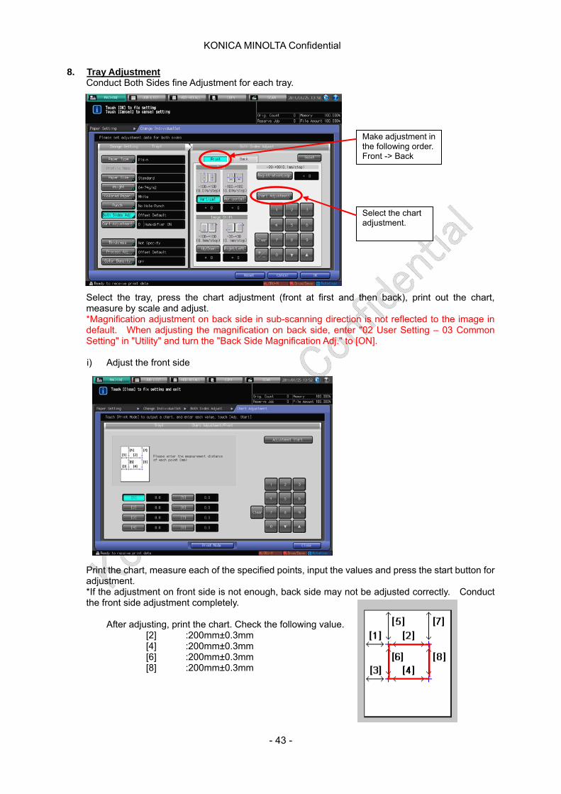
8. Tray Adjustment Conduct Both Sides fine Adjustment for each tray.
Select the tray, press the chart adjustment (front at first and then back), print out the chart, measure by scale and adjust. *Magnification adjustment on back side in sub-scanning direction is not reflected to the image in default. When adjusting the magnification on back side, enter "02 User Setting – 03 Common Setting" in "Utility" and turn the "Back Side Magnification Adj." to [ON].
Select the chart adjustment.
Make adjustment in the following order. Front -> Back
i) Adjust the front side
Print the chart, measure each of the specified points, input the values and press the start button for adjustment. *If the adjustment on front side is not enough, back side may not be adjusted correctly. Conduct the front side adjustment completely.
After adjusting, print the chart. Check the following value. [2] :200mm±0.3mm [4] :200mm±0.3mm [6] :200mm±0.3mm [8] :200mm±0.3mm
- 43 -
KONICA MINOLTA Confidential
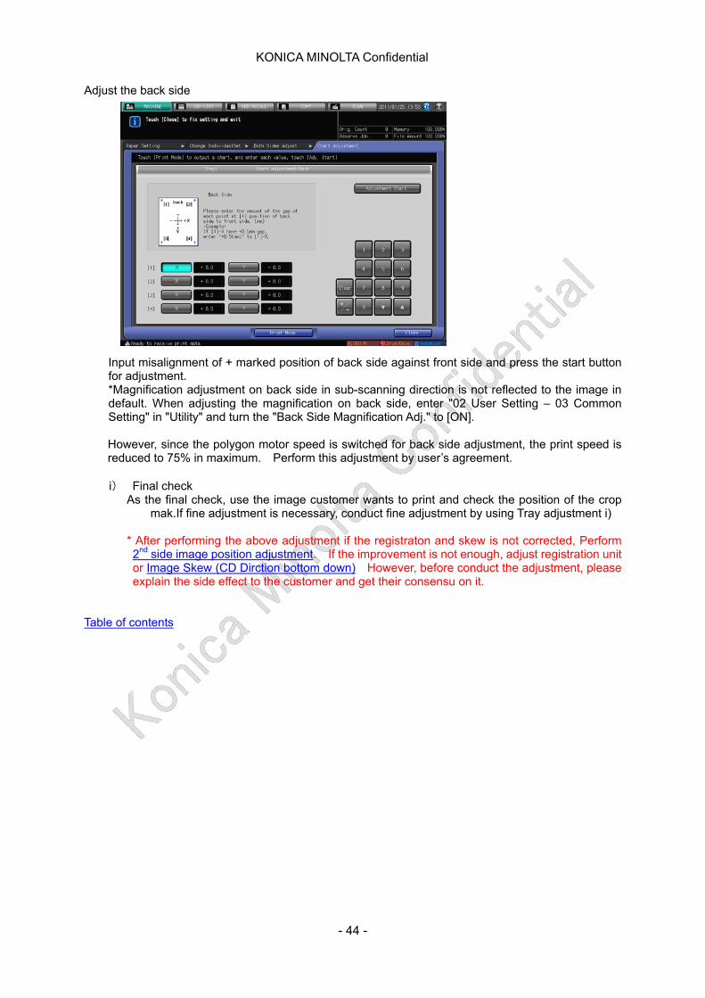
Adjust the back side
Input misalignment of + marked position of back side against front side and press the start button for adjustment. *Magnification adjustment on back side in sub-scanning direction is not reflected to the image in default. When adjusting the magnification on back side, enter "02 User Setting – 03 Common Setting" in "Utility" and turn the "Back Side Magnification Adj." to [ON].
However, since the polygon motor speed is switched for back side adjustment, the print speed is reduced to 75% in maximum. Perform this adjustment by user’s agreement.
i) Final check
As the final check, use the image customer wants to print and check the position of the crop mak.If fine adjustment is necessary, conduct fine adjustment by using Tray adjustment i)
* After performing the above adjustment if the registraton and skew is not corrected, Perform 2nd side image position adjustment. If the improvement is not enough, adjust registration unit or Image Skew (CD Dirction bottom down) However, before conduct the adjustment, please explain the side effect to the customer and get their consensu on it.
Table of contents
- 44 -

KONICA MINOLTA Confidential
II-a-1. Cyclic white spot/black spot
1. Symptom White spot/black spot repeatedly occurs at a certain cycle.
2. Cause
a) Drum unit
Approx. 188mm cycle in a single color
b) Developing unit
Approx. 53mm cycle in a single color
c) Intermediate transfer belt Approx. 861mm interval.
d) 2nd transfer roller
Approx. 95mm interval.
e) Fusing belt
Approx. 251mm interval. On simplex printing, the symptom occurs on 2nd side.
3. Solution After specifying the problem parts, clean and replace the subject parts.
Table of contents
- 45 -
KONICA MINOLTA Confidential
II-b-1. Line and uneven density countermeasure flow 1. How to distinguish the line problem and uneven density problem (1) Conduct the gamma auto adjustment
- [Service Mode]-[02 Process Adjustment]-[02 Drum Peculiarity Adj.]-[02 Auto gamma adjustment]- [Adjustment]-[03 Execute Adjustment Operation]-[Auto Gamma Adj.]
* Which method you take, there is no difference in operation.
(2) Print the following test pattern using paper bigger than A3 size. - No.53: Print each of YMCK in single color and in density 120 and 255. Set the density to 0 for all the colors other than you print. Use the Dot1 screen. - Select No.53, set the density of YMCK to 120 and print the 4 color gray. - Select No.58 and set the density of MCK to 120. Use the Dot1 screen.
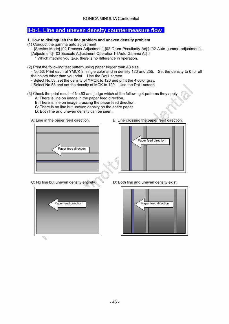
(3) Check the print result of No.53 and judge which of the following 4 patterns they apply. A: There is line on image in the paper feed direction. B: There is line on image crossing the paper feed direction. C: There is no line but uneven density on the entire paper. D: Both line and uneven density can be seen.
A: Line in the paper feed direction. B: Line crossing the paper feed direction.
Paper feed direction
Paper feed direction
C: No line but uneven density entirely. D: Both line and uneven density exist.
Paper feed direction Paper feed direction
- 46 -
KONICA MINOLTA Confidential
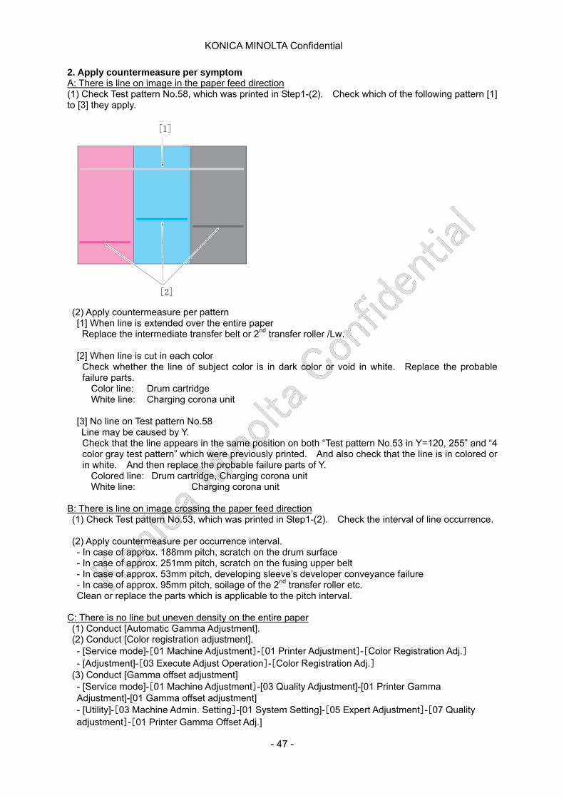
2. Apply countermeasure per symptom A: There is line on image in the paper feed direction (1) Check Test pattern No.58, which was printed in Step1-(2). Check which of the following pattern [1] to [3] they apply.
[2]
[1] (2) Apply countermeasure per pattern
[1] When line is extended over the entire paper Replace the intermediate transfer belt or 2nd transfer roller /Lw.
[2] When line is cut in each color Check whether the line of subject color is in dark color or void in white. Replace the probable failure parts.
Color line: Drum cartridge White line: Charging corona unit
[3] No line on Test pattern No.58 Line may be caused by Y.
Check that the line appears in the same position on both “Test pattern No.53 in Y=120, 255” and “4 color gray test pattern” which were previously printed. And also check that the line is in colored or in white. And then replace the probable failure parts of Y.
Colored line: Drum cartridge, Charging corona unit White line: Charging corona unit
B: There is line on image crossing the paper feed direction (1) Check Test pattern No.53, which was printed in Step1-(2). Check the interval of line occurrence. (2) Apply countermeasure per occurrence interval.
- In case of approx. 188mm pitch, scratch on the drum surface - In case of approx. 251mm pitch, scratch on the fusing upper belt - In case of approx. 53mm pitch, developing sleeve’s developer conveyance failure - In case of approx. 95mm pitch, soilage of the 2nd transfer roller etc. Clean or replace the parts which is applicable to the pitch interval.
C: There is no line but uneven density on the entire paper (1) Conduct [Automatic Gamma Adjustment]. (2) Conduct [Color registration adjustment]. - [Service mode]-[01 Machine Adjustment]-[01 Printer Adjustment]-[Color Registration Adj.] - [Adjustment]-[03 Execute Adjust Operation]-[Color Registration Adj.]
(3) Conduct [Gamma offset adjustment] - [Service mode]-[01 Machine Adjustment]-[03 Quality Adjustment]-[01 Printer Gamma Adjustment]-[01 Gamma offset adjustment] - [Utility]-[03 Machine Admin. Setting]-[01 System Setting]-[05 Expert Adjustment]-[07 Quality adjustment]-[01 Printer Gamma Offset Adj.]
- 47 -
KONICA MINOLTA Confidential
(4) Conduct [Density Balance Adjustment].
- [Adjustment]-[05 Density Balance Adjustment] Refer to [Density Balance Adjustment].
D: Both line and uneven density can be seen (1) Remove the causes of line by conducting the countermeasure for case A and B. (2) Line became less visible, conduct the countermeasure for case C. Caution ) When replacing the failure parts, do not jump to replace with the brand new parts but try using the old parts attached to used machines. Upon knowing how the symptom is improved with the replacement, replace with the prepared new parts. If there is no improvement by replacing parts, consider other causes. Table of contents
- 48 -
KONICA MINOLTA Confidential
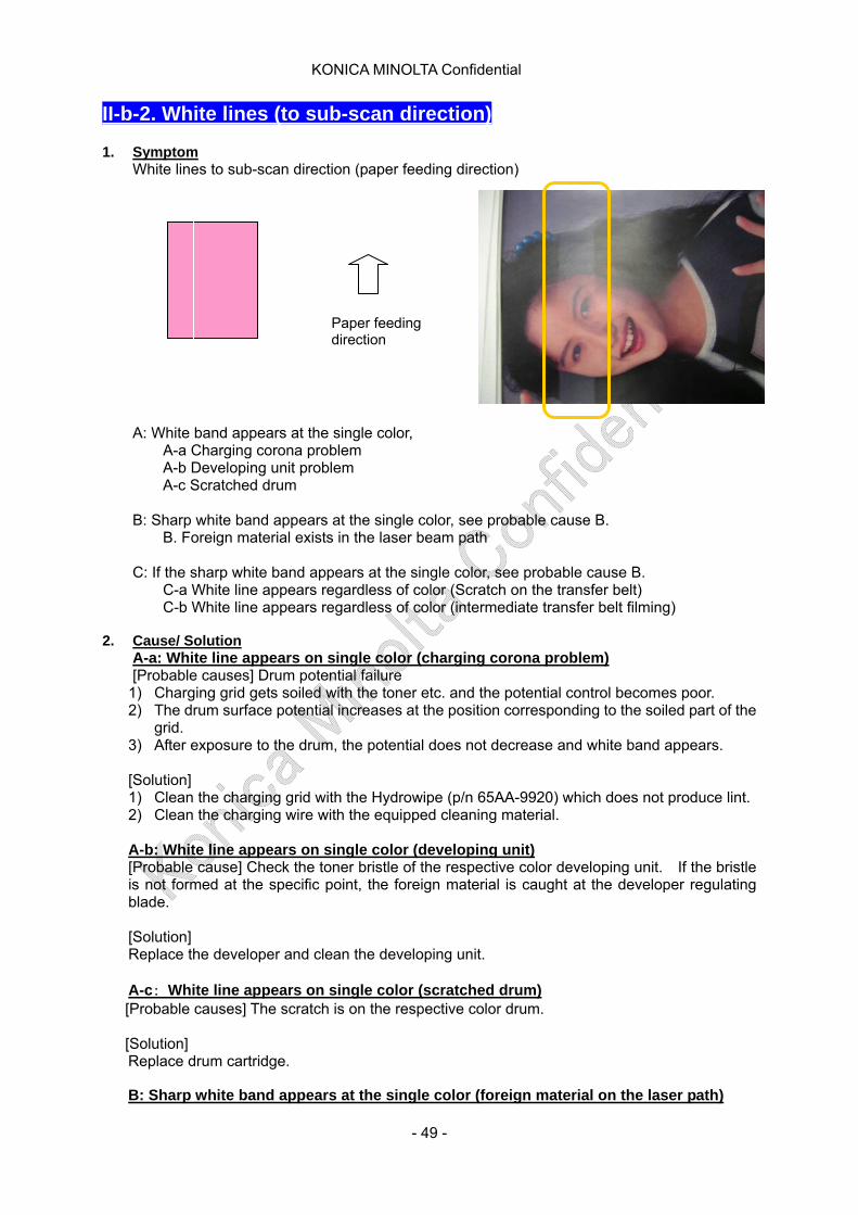
II-b-2. White lines (to sub-scan direction) 1. Symptom
White lines to sub-scan direction (paper feeding direction)
A: White band appears at the single color,
Paper feeding direction
A-a Charging corona problem A-b Developing unit problem A-c Scratched drum
B: Sharp white band appears at the single color, see probable cause B.
B. Foreign material exists in the laser beam path
C: If the sharp white band appears at the single color, see probable cause B. C-a White line appears regardless of color (Scratch on the transfer belt) C-b White line appears regardless of color (intermediate transfer belt filming)
2. Cause/ Solution
A-a: White line appears on single color (charging corona problem) [Probable causes] Drum potential failure
1) Charging grid gets soiled with the toner etc. and the potential control becomes poor. 2) The drum surface potential increases at the position corresponding to the soiled part of the
grid. 3) After exposure to the drum, the potential does not decrease and white band appears.
[Solution] 1) Clean the charging grid with the Hydrowipe (p/n 65AA-9920) which does not produce lint. 2) Clean the charging wire with the equipped cleaning material.
A-b: White line appears on single color (developing unit) [Probable cause] Check the toner bristle of the respective color developing unit. If the bristle is not formed at the specific point, the foreign material is caught at the developer regulating blade.
[Solution] Replace the developer and clean the developing unit.
A-c: White line appears on single color (scratched drum) [Probable causes] The scratch is on the respective color drum.
[Solution] Replace drum cartridge.
B: Sharp white band appears at the single color (foreign material on the laser path)
- 49 -
KONICA MINOLTA Confidential
[Probable cause] Dust, toner and so son attaches to the light path for the image wiring and locks the laser beam, causing white band to appear.
[Solution] Clean the soil and dust which block the light path with the Hydrowipe. (Specifically, the lower part of the developing casing.)
C-a: White line appears at the single color (intermediate transfer belt filming) [Probable cause] Filming of intermediate transfer belt sometimes occurs and the belt resistance changes. As the result, poor transfer occurs and white band appears.
[Solution] Adjustment => [03 Execute Adjustment] => Perform [Belt refresh mode] Only one time as the maximum. Toner consumption per one time adjustment is: C and M toner A3 solid 5 sheets equivalent
Filming tends to occur with the frequent print of low coverage or B5 or 5”1/2×8”1/2 or less size.
CAUTION: Do not perform belt refresh or toner refresh more than specified maximum times. Otherwise, toner cleaning failure and other problem may occurs. During the BT developing process, belt refresh or toner refresh is rarely used and BT presumed refresh mode is basically not needed.
Table of contents
- 50 -
KONICA MINOLTA Confidential
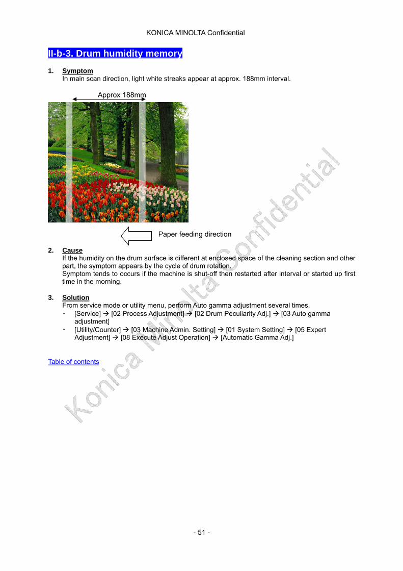
II-b-3. Drum humidity memory 1. Symptom
In main scan direction, light white streaks appear at approx. 188mm interval.
Approx 188mm
Paper feeding direction 2. Cause
If the humidity on the drum surface is different at enclosed space of the cleaning section and other part, the symptom appears by the cycle of drum rotation. Symptom tends to occurs if the machine is shut-off then restarted after interval or started up first time in the morning.
3. Solution
From service mode or utility menu, perform Auto gamma adjustment several times. ・ [Service] [02 Process Adjustment] [02 Drum Peculiarity Adj.] [03 Auto gamma
adjustment] ・ [Utility/Counter] [03 Machine Admin. Setting] [01 System Setting] [05 Expert
Adjustment] [08 Execute Adjust Operation] [Automatic Gamma Adj.] Table of contents
- 51 -

KONICA MINOLTA Confidential
II-b-4. Gloss line caused by fusing paper exit roller 1. Symptom
When printing the high coverage original, gloss line may occur on image.
2. Cause a) Fusing paper exit roller
When paper passes through the fusing unit, the fusing paper exit roller and the paper surface contact each other, which lowers the temperature of contacting area. The difference of gloss level between contacting area and non-contacting area causes gloss lines.
3. Solution a) Change pressure of the fusing paper exit roller
Change pressure of the fusing paper exit roller to release position.
<Limitation> When releasing the fusing paper exit roller, if the length of conveyance direction (FD) is shorter than A4, paper cannot feed. However, 4 imposing postal card can feed.
Default
Pressure Release
b) Change of fusing temperature If the symptom is not improved enough by performing a), lower the fusing temperature as follows. i) Change DipSW 1-0 to 1 (to display process adjustment screen to user screen).
[Service mode] [03 System setting] [01 Software DIPSW setting] i) Lower the temperature by 10 degrees Celsius for each of followings.
[Paper Setting] [Change Setting] [Process Adj.]
Table of contents
- 52 -
KONICA MINOLTA Confidential
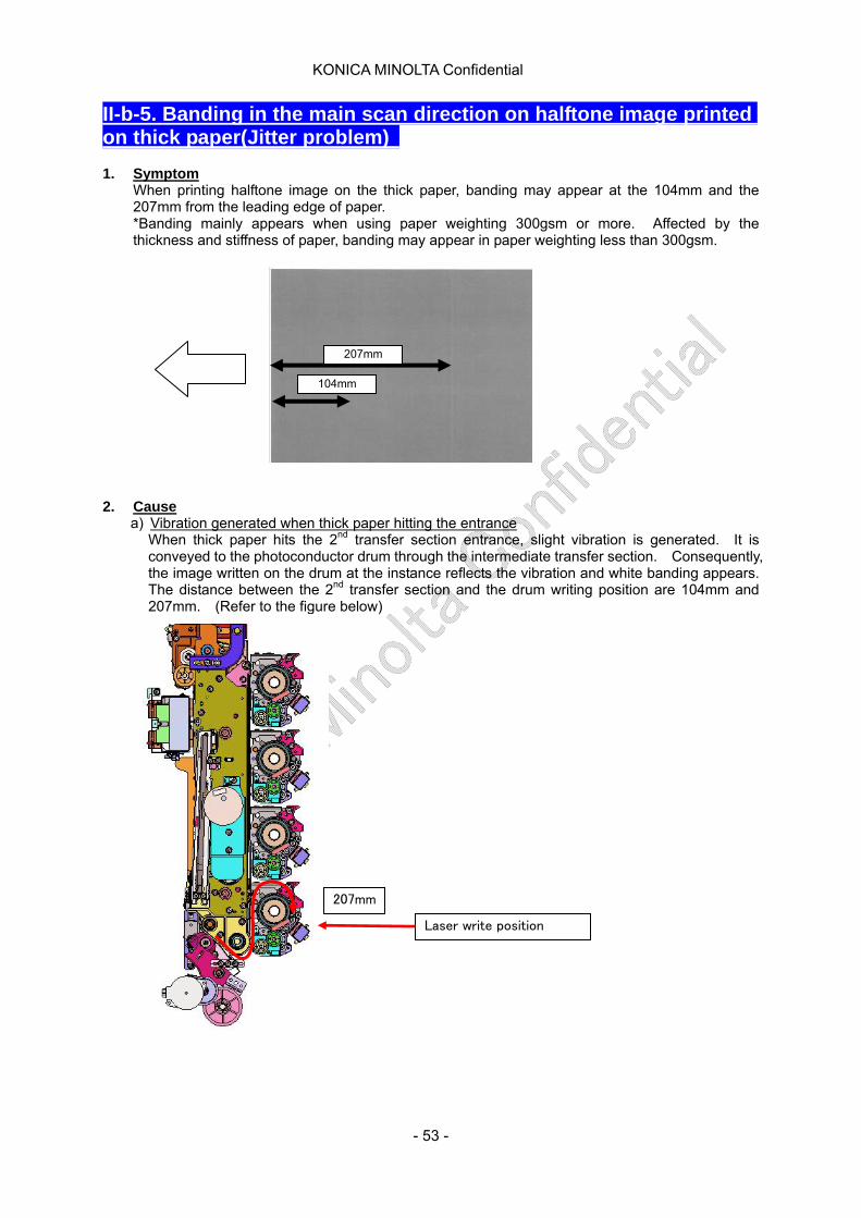
II-b-5. Banding in the main scan direction on halftone image printed on thick paper(Jitter problem) 1. Symptom
When printing halftone image on the thick paper, banding may appear at the 104mm and the 207mm from the leading edge of paper. *Banding mainly appears when using paper weighting 300gsm or more. Affected by the thickness and stiffness of paper, banding may appear in paper weighting less than 300gsm.
104mm
207mm
2. Cause
a) Vibration generated when thick paper hitting the entrance When thick paper hits the 2nd transfer section entrance, slight vibration is generated. It is conveyed to the photoconductor drum through the intermediate transfer section. Consequently, the image written on the drum at the instance reflects the vibration and white banding appears. The distance between the 2nd transfer section and the drum writing position are 104mm and 207mm. (Refer to the figure below)
207mm
Laser write position
- 53 -
KONICA MINOLTA Confidential
3. Solution a) Noticeable banding on black halftone
i) Changing the screen type. [Utility] [03 Machine Admin. Setting] [01 System Setting] [05 Expert adjustment]
[07 Quality Adjustment] [05 Custom Screen] *Dot130(Dot2 at default) is recommended. *After changing the screen type, perform [Gamma offset adjustment].
If the symptom is not improved enough by performing i), try following procedure. ii) Change DIPSW11-5(Thick paper Bk mode) to 1(ON).
Service mode 03 System Setting 01 Software DIPSW Setting iii) By changing [Thick paper BK mode] to ON, even for single black printing, YMC first transfer
rollers are pressed to reduce the vibration. [Utility] [02 User Setting] [03 Common Setting] [Thick paper BK mode] *If above setting is selected, color process related parts (charging corona, drum, developing unit, developer, 1st transfer roller) are consumed even in Bk printing. Also, when [Thick paper BK mode] is enabled, toner scattering may occur. It is recommended to disable [Thick paper BK mode] when the function is not needed.
If the symptom is not improved enough by performing ii) and iii), try following procedure. iv) Change DipSW 1-0 to 1 (to display process adjustment screen to user screen).
[Service mode] [03 System Setting] [01 Software DIPSW Setting] v) At the [Weight], select the lighter weight than actually used paper and increase line speed.
[Paper Setting] [Change Setting] [Weight] *At first, try from 3/4 speed. (3/4 speed for 209gsm or less, 1/1 speed for 135gsm or less)
vi) If v) is performed, fusing time is reduced and fusing failure may occur. In that case, change the value of following 5 settings. [Paper Setting] [Change Setting] [Process Adj.] [Next]
[Fusing Roller Center Tem.(Print)] [Fusing Roller Edge Temp.(Print)] [Fusing Under Belt Center Temp.(Print)] [Fus. Out Heat Center Temp.(Print)] [Fus. Out Heat Edge Temp. (Print)]
*At first, enter ”+5” for trial. If the improvement level is not enough, enter “+10.” vii) Additionally, depending on paper, banding cannot be solved completely. If the improvement
level is not enough, please request your customer to try another kind of paper.
Table of contents
- 54 -

KONICA MINOLTA Confidential
II-b-6. Line like ripple on image 1. Symptom
Unevenness in the main scan direction (CD) occurs on solid image with 2 (or more) colors.
2. Cause
a) Low toner charge under the humidity environment When toner charge is increased under the low humidity environment, the leak occurs at the 1st transfer section.
b) Excessive toner amount at the 1st transfer section When the density is high at the solid 2 color section, the leak occurs at the 1st transfer section.
3. Solution
a) Low toner charge under the humidity environment i) Perform the gamma automatic adjustment.
[Service] [02 Process Adjustment] [02 Drum Peculiarity Adjustment] [02 Gamma Automatic Adjustment]
ii) If the first transfer current is decreased too much, the white spot may appear. Please mind
it and check the image carefully when performing the adjustment. Excessive toner amount at the 1st transfer section
ii) After performing i) to iv) and still the symptom is not improved, lower the max-density to decrease the fusing toner amount. [03 Administrator Setting] [01 System Setting] [05 Expert Adjustment] [06 Process Adjustment] [03 Maximum Density Adjustment] Set the transfer out setting, which is changed in the iii), back to 0. Based on the color produced, decrease the maximum density of single color by -2 steps and check if the symptom is improved.
Table of contents
- 55 -
KONICA MINOLTA Confidential
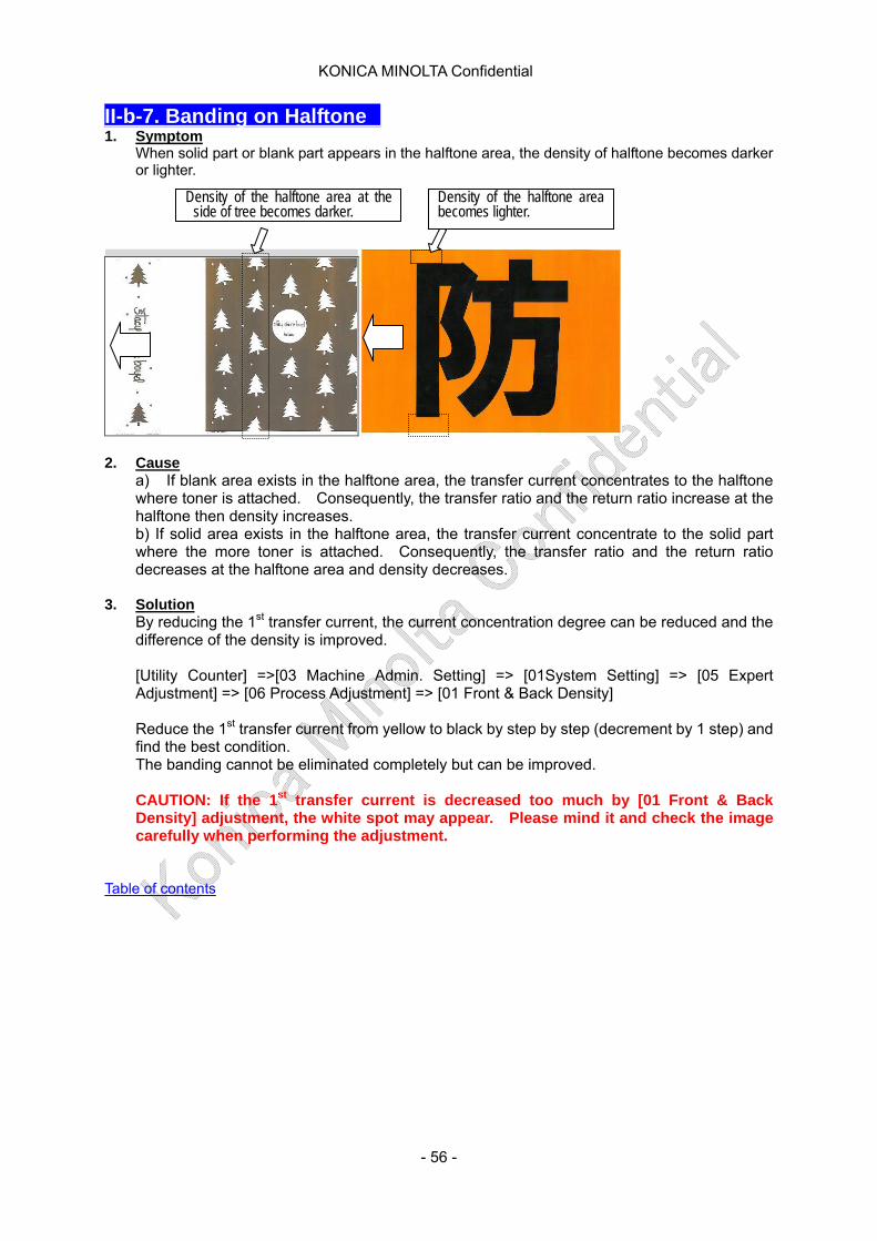
II-b-7. Banding on Halftone 1. Symptom
When solid part or blank part appears in the halftone area, the density of halftone becomes darker or lighter.
Density of the halftone area at the side of tree becomes darker.
Density of the halftone area becomes lighter.
2. Cause
a) If blank area exists in the halftone area, the transfer current concentrates to the halftone where toner is attached. Consequently, the transfer ratio and the return ratio increase at the halftone then density increases. b) If solid area exists in the halftone area, the transfer current concentrate to the solid part where the more toner is attached. Consequently, the transfer ratio and the return ratio decreases at the halftone area and density decreases.
3. Solution
By reducing the 1st transfer current, the current concentration degree can be reduced and the difference of the density is improved.
[Utility Counter] =>[03 Machine Admin. Setting] => [01System Setting] => [05 Expert Adjustment] => [06 Process Adjustment] => [01 Front & Back Density]
Reduce the 1st transfer current from yellow to black by step by step (decrement by 1 step) and find the best condition. The banding cannot be eliminated completely but can be improved.
CAUTION: If the 1st transfer current is decreased too much by [01 Front & Back Density] adjustment, the white spot may appear. Please mind it and check the image carefully when performing the adjustment.
Table of contents
- 56 -
KONICA MINOLTA Confidential
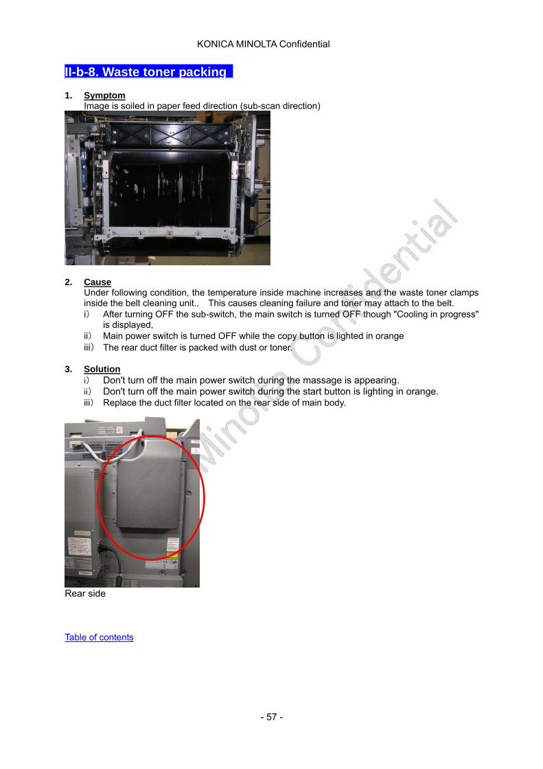
II-b-8. Waste toner packing 1. Symptom
Image is soiled in paper feed direction (sub-scan direction)
2. Cause
Under following condition, the temperature inside machine increases and the waste toner clamps inside the belt cleaning unit.. This causes cleaning failure and toner may attach to the belt. i) After turning OFF the sub-switch, the main switch is turned OFF though "Cooling in progress"
is displayed, ii) Main power switch is turned OFF while the copy button is lighted in orange iii) The rear duct filter is packed with dust or toner.
3. Solution
i) Don't turn off the main power switch during the massage is appearing. ii) Don't turn off the main power switch during the start button is lighting in orange. iii) Replace the duct filter located on the rear side of main body.
Rear side Table of contents
- 57 -
KONICA MINOLTA Confidential
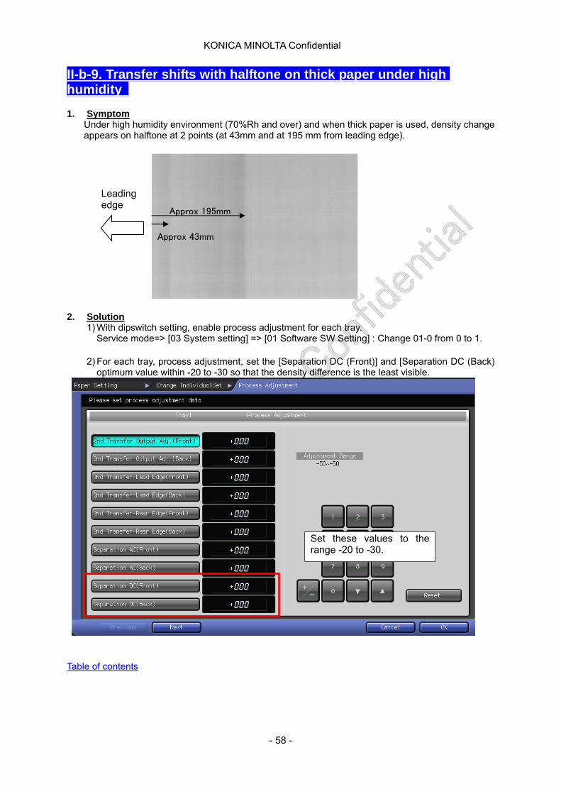
II-b-9. Transfer shifts with halftone on thick paper under high humidity 1. Symptom
Under high humidity environment (70%Rh and over) and when thick paper is used, density change appears on halftone at 2 points (at 43mm and at 195 mm from leading edge).
Leading edge
Approx 195mm
Approx 43mm
2. Solution
1) With dipswitch setting, enable process adjustment for each tray. Service mode=> [03 System setting] => [01 Software SW Setting] : Change 01-0 from 0 to 1.
2) For each tray, process adjustment, set the [Separation DC (Front)] and [Separation DC (Back)
optimum value within -20 to -30 so that the density difference is the least visible.
Set these values to the range -20 to -30.
Table of contents
- 58 -
KONICA MINOLTA Confidential
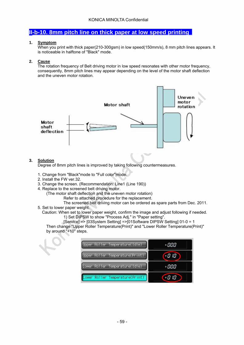
II-b-10. 8mm pitch line on thick paper at low speed printing 1. Symptom
When you print with thick paper(210-300gsm) in low speed(150mm/s), 8 mm pitch lines appears. It is noticeable in halftone of "Black" mode.
2. Cause The rotation frequency of Belt driving motor in low speed resonates with other motor frequency, consequently, 8mm pitch lines may appear depending on the level of the motor shaft deflection and the uneven motor rotation.
3. Solution Degree of 8mm pitch lines is improved by taking following countermeasures.
1. Change from "Black"mode to "Full color"mode. 2. Install the FW ver.32. 3. Change the screen. (Recommendation: Line1 (Line 190)) 4. Replace to the screened belt driving motor.
(The motor shaft deflection and the uneven motor rotation) Refer to attached procedure for the replacement. The screened belt driving motor can be ordered as spare parts from Dec. 2011.
5. Set to lower paper weight. Caution: When set to lower paper weight, confirm the image and adjust following if needed.
1) Set DIPSW to show "Process Adj." in "Paper setting". [Service] => [03System Setting] =>[01Software DIPSW Setting] 01-0 = 1
Then change "Upper Roller Temperature(Print)" and "Lower Roller Temperature(Print)" by around "+10" steps.
- 59 -
KONICA MINOLTA Confidential
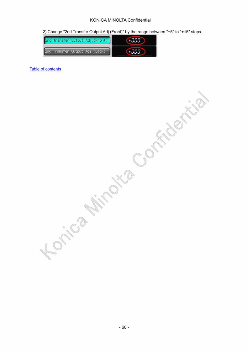
2) Change "2nd Transfer Output Adj.(Front)" by the range between "+5" to "+15" steps.
Table of contents
- 60 -
KONICA MINOLTA Confidential
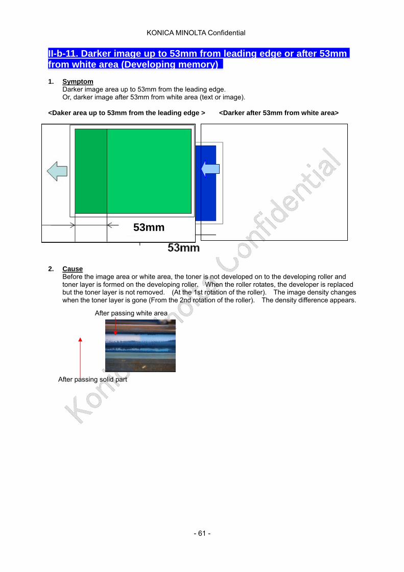
II-b-11. Darker image up to 53mm from leading edge or after 53mm from white area (Developing memory) 1. Symptom
Darker image area up to 53mm from the leading edge. Or, darker image after 53mm from white area (text or image).
<Daker area up to 53mm from the leading edge > <Darker after 53mm from white area>
53mm
2. Cause
Before the image area or white area, the toner is not developed on to the developing roller and toner layer is formed on the developing roller. When the roller rotates, the developer is replaced but the toner layer is not removed. (At the 1st rotation of the roller). The image density changes when the toner layer is gone (From the 2nd rotation of the roller). The density difference appears.
After passing white area
After passing solid part
- 61 -
KONICA MINOLTA Confidential
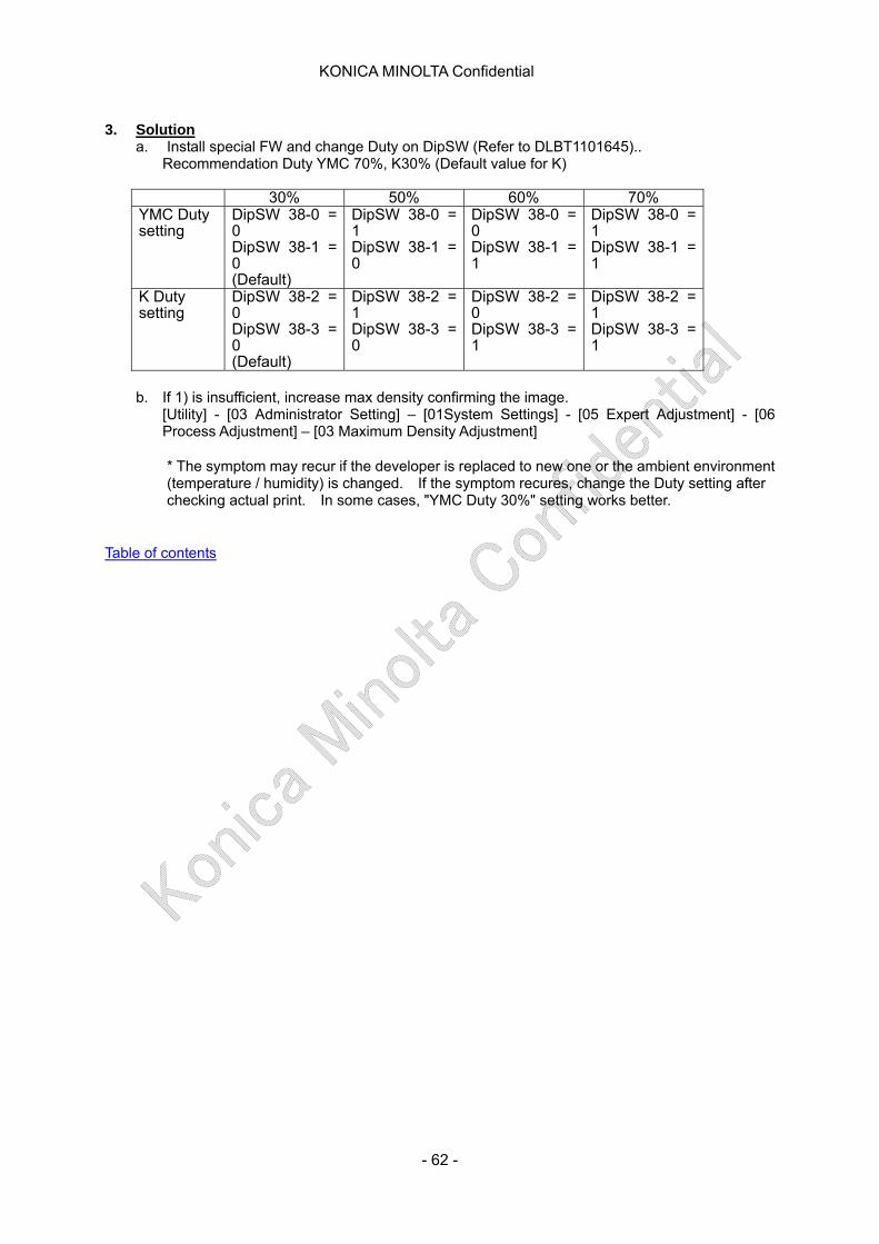
3. Solution
a. Install special FW and change Duty on DipSW (Refer to DLBT1101645).. Recommendation Duty YMC 70%, K30% (Default value for K)
30% 50% 60% 70% YMC Duty setting
DipSW 38-0 = 0 DipSW 38-1 = 0 (Default)
DipSW 38-0 = 1 DipSW 38-1 = 0
DipSW 38-0 = 0 DipSW 38-1 = 1
DipSW 38-0 = 1 DipSW 38-1 = 1
K Duty setting
DipSW 38-2 = 0 DipSW 38-3 = 0 (Default)
DipSW 38-2 = 1 DipSW 38-3 = 0
DipSW 38-2 = 0 DipSW 38-3 = 1
DipSW 38-2 = 1 DipSW 38-3 = 1
b. If 1) is insufficient, increase max density confirming the image.
[Utility] - [03 Administrator Setting] – [01System Settings] - [05 Expert Adjustment] - [06 Process Adjustment] – [03 Maximum Density Adjustment]
* The symptom may recur if the developer is replaced to new one or the ambient environment (temperature / humidity) is changed. If the symptom recures, change the Duty setting after checking actual print. In some cases, "YMC Duty 30%" setting works better.
Table of contents
- 62 -
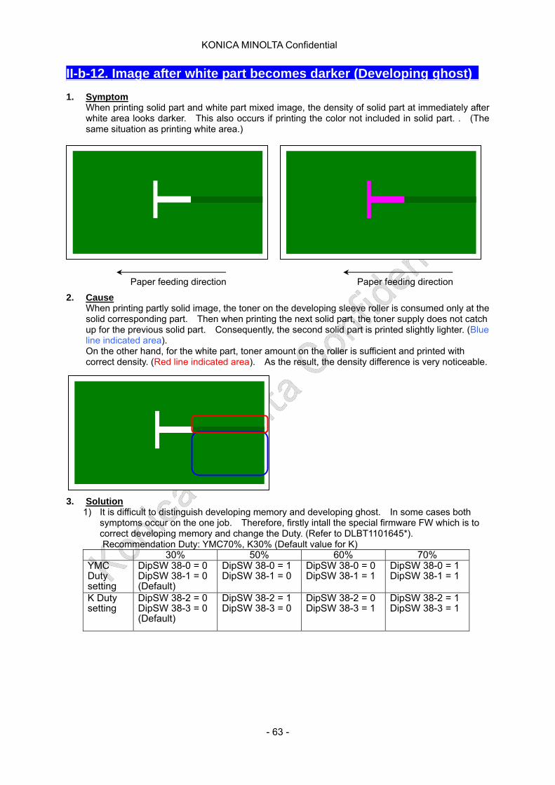
KONICA MINOLTA Confidential
II-b-12. Image after white part becomes darker (Developing ghost) 1. Symptom
When printing solid part and white part mixed image, the density of solid part at immediately after white area looks darker. This also occurs if printing the color not included in solid part. . (The same situation as printing white area.)
Paper feeding direction Paper feeding direction 2. Cause
When printing partly solid image, the toner on the developing sleeve roller is consumed only at the solid corresponding part. Then when printing the next solid part, the toner supply does not catch up for the previous solid part. Consequently, the second solid part is printed slightly lighter. (Blue line indicated area). On the other hand, for the white part, toner amount on the roller is sufficient and printed with correct density. (Red line indicated area). As the result, the density difference is very noticeable.
3. Solution
1) It is difficult to distinguish developing memory and developing ghost. In some cases both symptoms occur on the one job. Therefore, firstly intall the special firmware FW which is to correct developing memory and change the Duty. (Refer to DLBT1101645*). Recommendation Duty: YMC70%, K30% (Default value for K)
30% 50% 60% 70% YMC Duty setting
DipSW 38-0 = 0 DipSW 38-1 = 0 (Default)
DipSW 38-0 = 1 DipSW 38-1 = 0
DipSW 38-0 = 0 DipSW 38-1 = 1
DipSW 38-0 = 1 DipSW 38-1 = 1
K Duty setting
DipSW 38-2 = 0 DipSW 38-3 = 0 (Default)
DipSW 38-2 = 1 DipSW 38-3 = 0
DipSW 38-2 = 0 DipSW 38-3 = 1
DipSW 38-2 = 1 DipSW 38-3 = 1
- 63 -
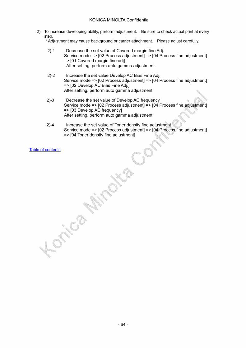
KONICA MINOLTA Confidential
2) To increase developing ability, perform adjustment. Be sure to check actual print at every step. * Adjustment may cause background or carrier attachment. Please adjust carefully. 2)-1 Decrease the set value of Covered margin fine Adj.
Service mode => [02 Process adjustment] => [04 Process fine adjustment] => [01 Covered margin fine adj]
After setting, perform auto gamma adjustment.
2)-2 Increase the set value Develop AC Bias Fine Adj. Service mode => [02 Process adjustment] => [04 Process fine adjustment]
=> [02 Develop AC Bias Fine Adj.] After setting, perform auto gamma adjustment.
2)-3 Decrease the set value of Develop AC frequency
Service mode => [02 Process adjustment] => [04 Process fine adjustment] => [03 Develop AC frequency]
After setting, perform auto gamma adjustment. 2)-4 Increase the set value of Toner density fine adjustment
Service mode => [02 Process adjustment] => [04 Process fine adjustment] => [04 Toner density fine adjustment]
Table of contents
- 64 -
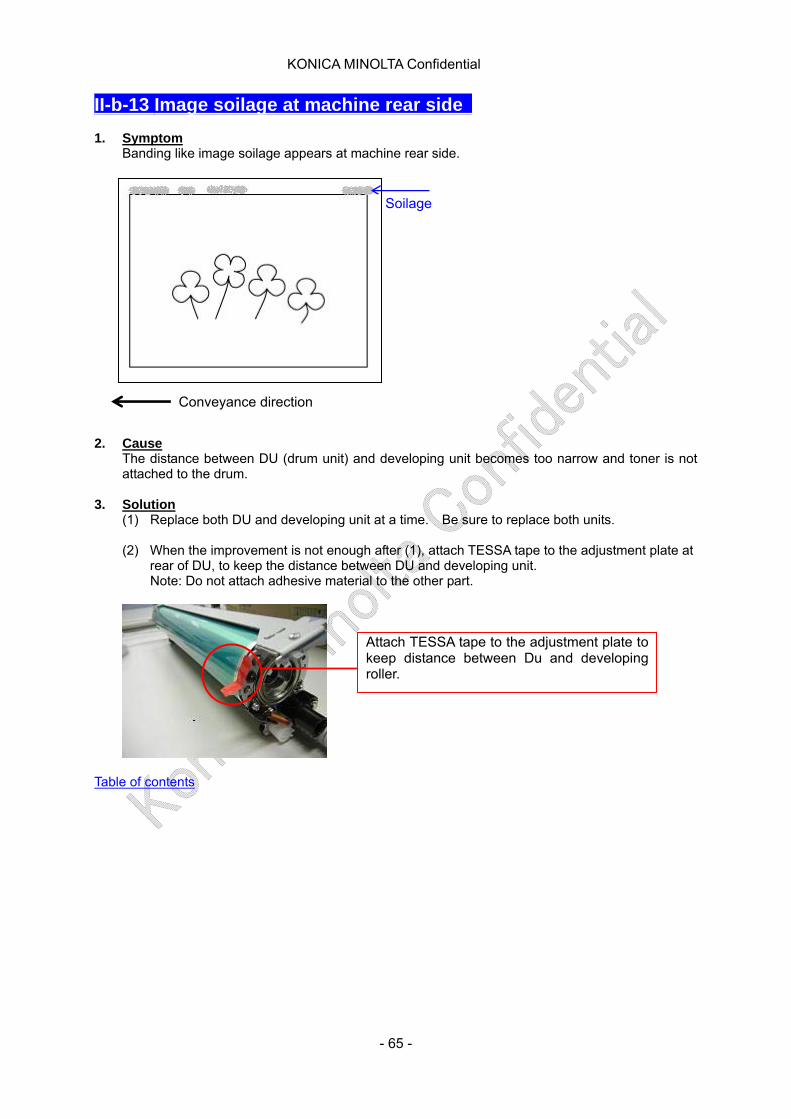
KONICA MINOLTA Confidential
II-b-13 Image soilage at machine rear side 1. Symptom
Banding like image soilage appears at machine rear side.
Soilage
Conveyance direction 2. Cause
The distance between DU (drum unit) and developing unit becomes too narrow and toner is not attached to the drum.
3. Solution
(1) Replace both DU and developing unit at a time. Be sure to replace both units. (2) When the improvement is not enough after (1), attach TESSA tape to the adjustment plate at
rear of DU, to keep the distance between DU and developing unit. Note: Do not attach adhesive material to the other part.
Attach TESSA tape to the adjustment plate to keep distance between Du and developing roller.
Table of contents
- 65 -

KONICA MINOLTA Confidential
II-c-1. Toner spilling 1. Symptom
Toner spills and attaches on the output irregularly. 2. Cause
Due to the toner scattering or background, the inside of the machine is soiled then toner falls on the paper path from the separation claws etc, causing the soil.
3. Solution 1) Check the status of dust proof filter/1 assembly (A1DUR703) t the right side of main body. If
too much toner scattering is confirmed, replace the filter, clean the developing unit upper cover (Fig.1) and process carriage (Fig 2) on which the developing unit is installed. Also, clean the drum cartridge stay (Fig.3)
Right side Filter/1 assembly
Clean developing unit upper cover
Fig. 1: Developing unit upper cover
Fig 2: Where should be cleaned on Process carriage
- 66 -
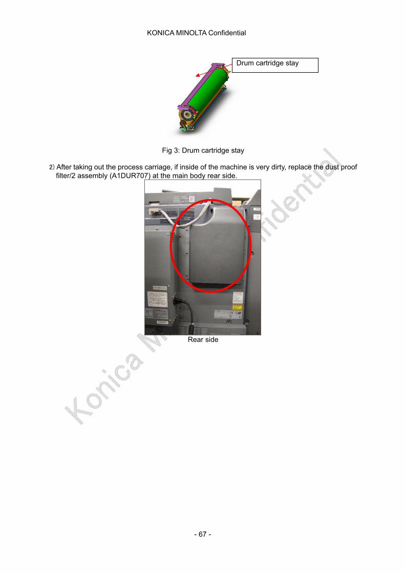
KONICA MINOLTA Confidential
Fig 3: Drum cartridge stay
2) After taking out the process carriage, if inside of the machine is very dirty, replace the dust proof
filter/2 assembly (A1DUR707) at the main body rear side.
Drum cartridge stay
Rear side
- 67 -
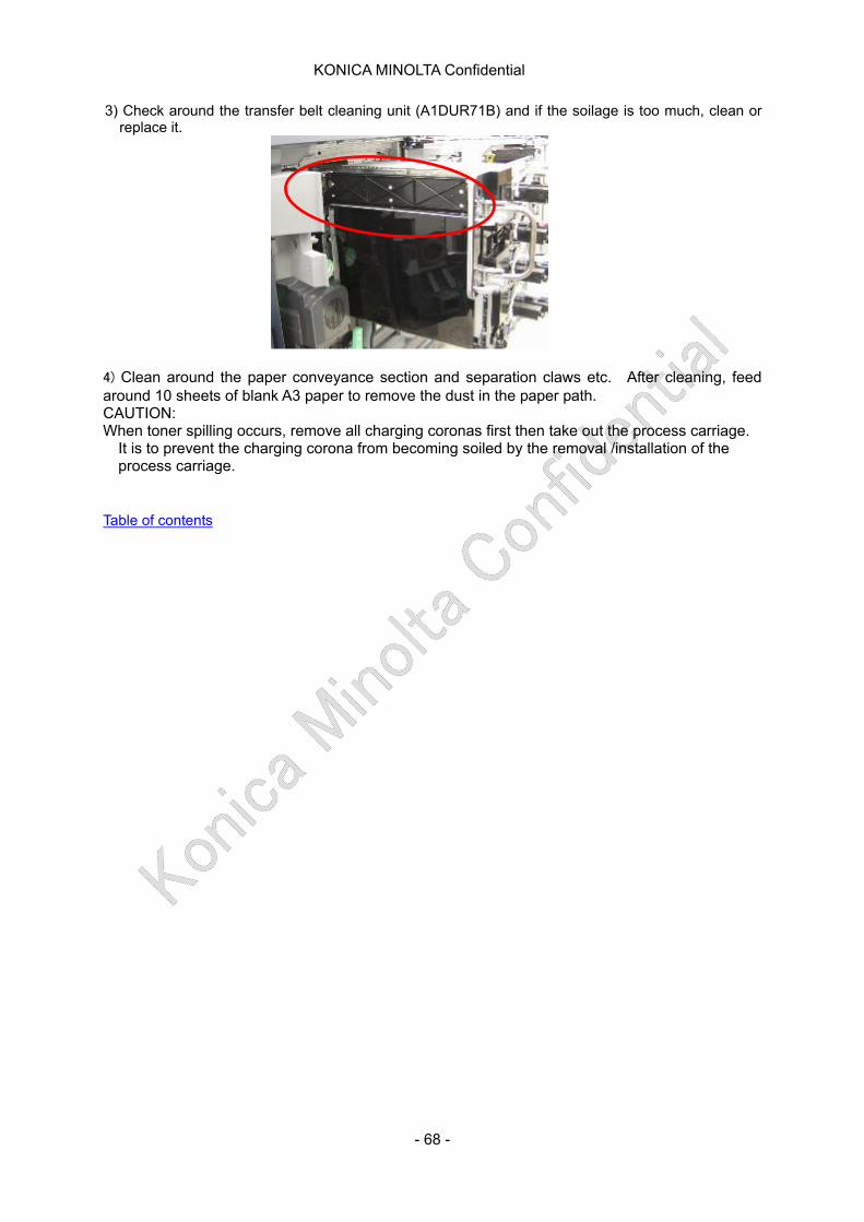
KONICA MINOLTA Confidential
3) Check around the transfer belt cleaning unit (A1DUR71B) and if the soilage is too much, clean or replace it.
4) Clean around the paper conveyance section and separation claws etc. After cleaning, feed around 10 sheets of blank A3 paper to remove the dust in the paper path. CAUTION: When toner spilling occurs, remove all charging coronas first then take out the process carriage.
It is to prevent the charging corona from becoming soiled by the removal /installation of the process carriage.
Table of contents
- 68 -
KONICA MINOLTA Confidential
II-c-2. Smear on mat-coated paper with half-tone image 1. Symptom
When printing half-tone image on mat-coated paper, toner is re-transfered to anotehr paper. The rear of the printed paper which is stacked on top gets soiled during continuous printing.
2. Cause
The gloss of mat-coated paper is controled by the surface processing which is to make the coated surface rough. The stacked paper rub the transfered toner, causing smear.
3. Solution
(1) Increase fusing temperature. (Check the image quality and fusing ability at every step of adjustment.)
(1)-1 [Paper setting] => [Change Set] => [Process Adj.] => [Upper Roller emperature(Idle)]/ [Upper Roller Temparature(Print)] => Set each to +10 (1)-2 [Paper setting] => [Change Set] => [Process Adj.] => [Lower Roller Temperature(Idle)]/ [Lower Roller Temperature(Print)] => Set each to +20 (1)-3 Set DIP SW [Service] => [System Setting] => [Software DIPSW Setting] => 19-1=0,19-2=0,19-3=1(Upper Roller+10)
(2) Decrease process speed
[Paper setting] => [Change Set] => 「Process Adj.」 => [Speed Down] =>OFF
(3) Change type of paper Change paper type to high quality paper which has similar texture of mat-coated paper
Table of contents
- 69 -
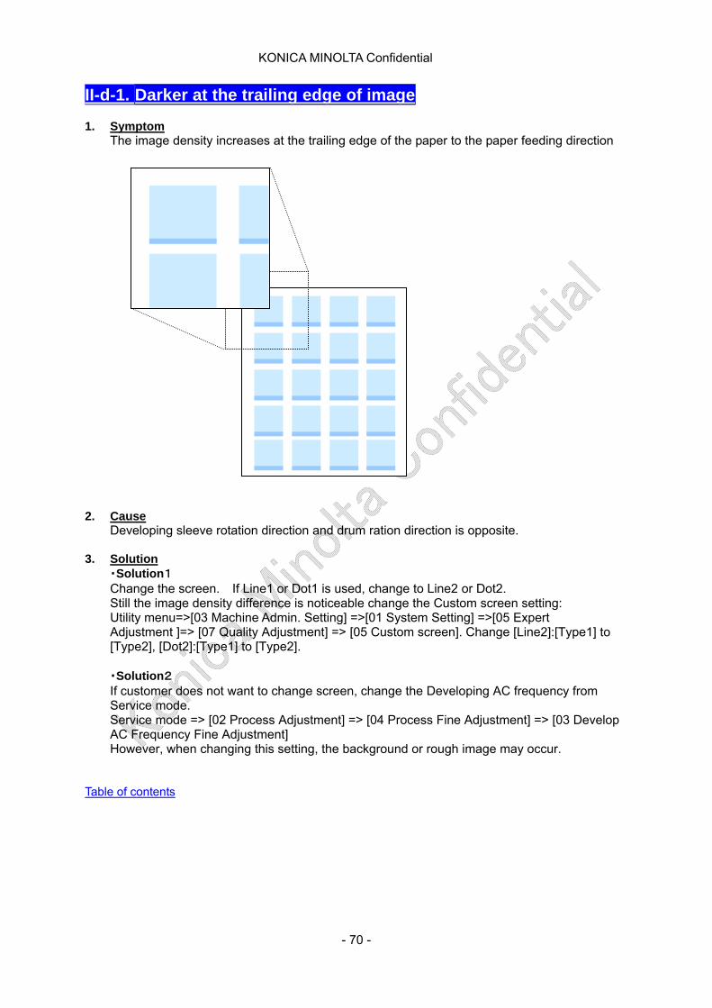
KONICA MINOLTA Confidential
II-d-1. Darker at the trailing edge of image 1. Symptom
The image density increases at the trailing edge of the paper to the paper feeding direction 2. Cause
Developing sleeve rotation direction and drum ration direction is opposite. 3. Solution
・Solution1 Change the screen. If Line1 or Dot1 is used, change to Line2 or Dot2. Still the image density difference is noticeable change the Custom screen setting: Utility menu=>[03 Machine Admin. Setting] =>[01 System Setting] =>[05 Expert Adjustment ]=> [07 Quality Adjustment] => [05 Custom screen]. Change [Line2]:[Type1] to [Type2], [Dot2]:[Type1] to [Type2].
・Solution2 If customer does not want to change screen, change the Developing AC frequency from Service mode. Service mode => [02 Process Adjustment] => [04 Process Fine Adjustment] => [03 Develop AC Frequency Fine Adjustment] However, when changing this setting, the background or rough image may occur.
Table of contents
- 70 -
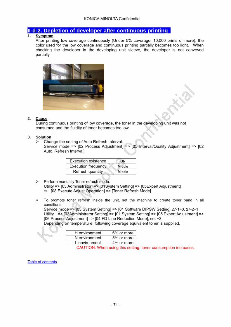
KONICA MINOLTA Confidential
II-d-2. Depletion of developer after continuous printing 1. Symptom
After printing low coverage continuously (Under 5% coverage, 10,000 prints or more), the color used for the low coverage and continuous printing partially becomes too light. When checking the developer in the developing unit sleeve, the developer is not conveyed partially.
2. Cause
During continuous printing of low coverage, the toner in the developing unit was not consumed and the fluidity of toner becomes too low.
3. Solution
Change the setting of Auto Refresh Interval. Service mode => [02 Process Adjustment] => [05 Interval/Quality Adjustment] => [02 Auto. Refresh Interval]
Execution existence ON
Execution frequency Middle
Refresh quantity Middle
Perform manually Toner refresh mode.
Utility => [03 Administrator] => [01System Setting] => [05Expert Adjustment] [08 Execute Adjust Operation] => [Toner Refresh Mode]
To promote toner refresh inside the unit, set the machine to create toner band in all
conditions. Service mode => [03 System Setting] => [01 Software DIPSW Setting] 27-1=0, 27-2=1 Utility => [03Administrator Setting] => [01 System Setting] => [05 Expert Adjustment] => [06 Process Adjustment] => [04 FD Line Reduction Mode], set +3. Depending on temperature, following coverage equivalent toner is supplied.
H environment 6% or more N environment 5% or moreL environment 4% or more
CAUTION: When using this setting, toner consumption increases. Table of contents
- 71 -

KONICA MINOLTA Confidential
II-d-3. Image skew (CD skew : bottom down direction) 1. Symptom
On C7000/C6000/C7000P/C70hc/+6000/+7000, the image skew has occurred. The image skew to the right side down direction against conveyance direction occurs to CD and FD. (Common for PFU, LU and main body tray)
2. Cause The cause of the skew is specified as the distortion of the standard board for the machine rear. The standard board rear got distorted while assmbling the main frame. BT already improved manufacturing process and assmbling jig has been modified and
the control item has been increased to prevent the distortion.
3. Solution Install the countermeasure parts and adjust the skew. Intermediate transfer positioning shaft (lower) installation procedure (Skew countermeasure in the field)
Countermeasure parts set (A1DUR90100): Following 3 parts. 1. Positioning shaft: 1.0mm eccentric 2. Spacer 3. M4x10 TP screw
Permanent Countermeasure Serial number cut in: (From February 2011 production)
Permanent Countermeasurehe (Frame of main body is corrected) has already installed for above S/N machines.
- 72 -
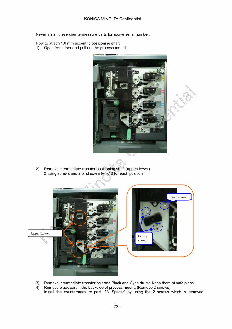
KONICA MINOLTA Confidential
Never install these countermeasure parts for above serial number. How to attach 1.0 mm eccentric positioning shaft 1) Open front door and pull out the process mount.
2) Remove intermediate transfer positioning shaft (upper/ lower) 2 fixing screws and a bind screw M4x10 for each position
Bind screw
Fixing screw
Upper/Lower
3) Remove intermediate transfer belt and Black and Cyan drums.Keep them at safe place. 4) Remove black part in the backside of process mount. (Remove 2 screws)
Install the countermeasure part "3. Spacer" by using the 2 screws which is removed.
- 73 -
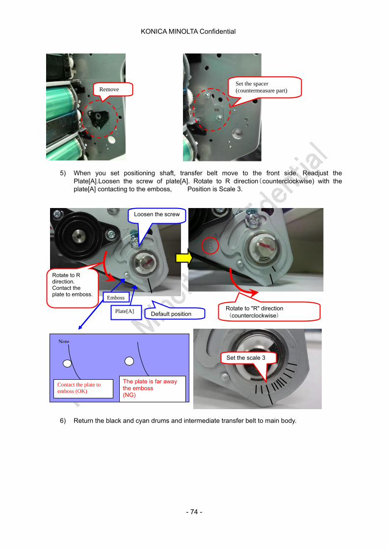
KONICA MINOLTA Confidential
5) When you set positioning shaft, transfer belt move to the front side. Readjust the Plate[A].Loosen the screw of plate[A]. Rotate to R direction(counterclockwise) with the plate[A] contacting to the emboss, Position is Scale 3.
Remove Set the spacer (countermeasure part)
Plate[A] Default position
R
Rotate to R direction. Contact the plate to emboss.
Emboss
Rotate to "R" direction (counterclockwise)
Contact the plate to emboss (OK)
Note
Set the scale 3
The plate is far away the emboss (NG)
Loosen the screw
6) Return the black and cyan drums and intermediate transfer belt to main body.
- 74 -
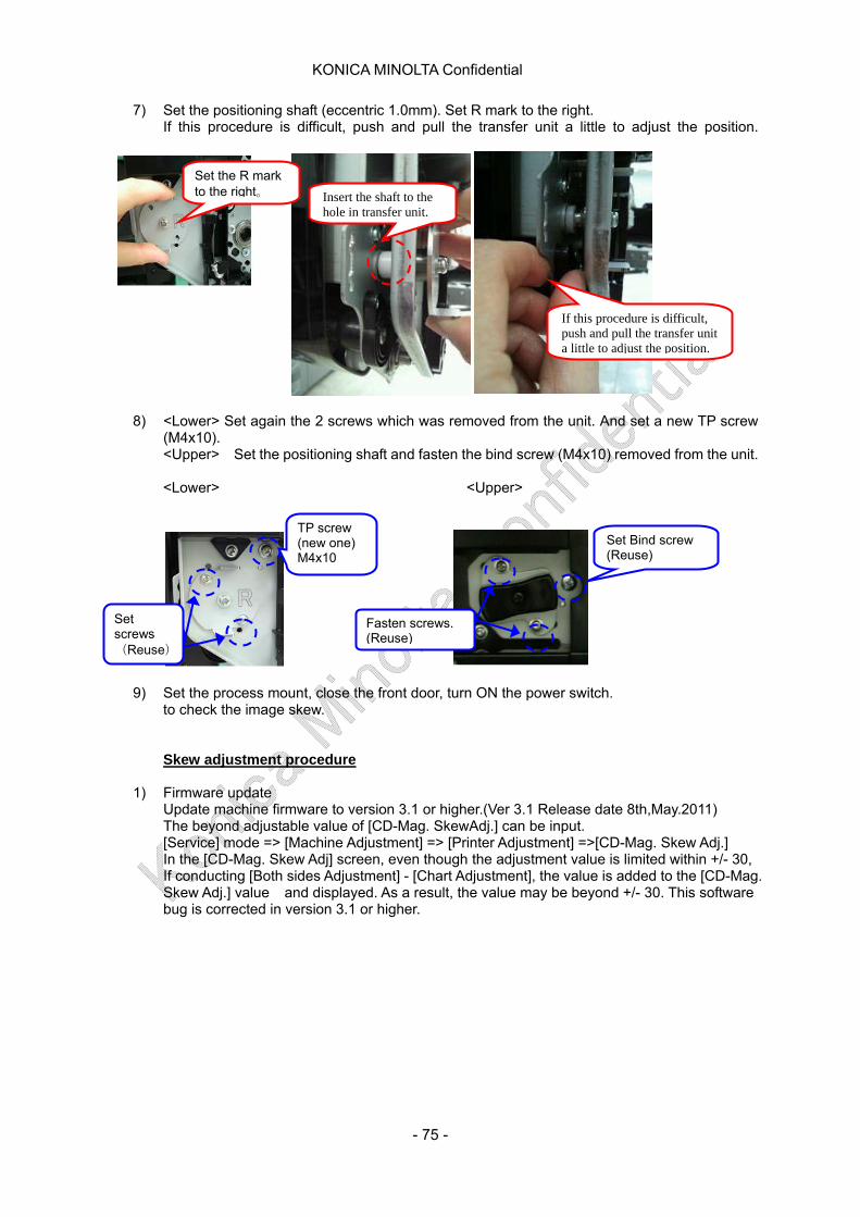
KONICA MINOLTA Confidential
7) Set the positioning shaft (eccentric 1.0mm). Set R mark to the right. If this procedure is difficult, push and pull the transfer unit a little to adjust the position.
Insert the shaft to the hole in transfer unit.
Set the R mark to the right。
If this procedure is difficult, push and pull the transfer unit a little to adjust the position.
8) <Lower> Set again the 2 screws which was removed from the unit. And set a new TP screw (M4x10). <Upper> Set the positioning shaft and fasten the bind screw (M4x10) removed from the unit.
<Lower> <Upper>
TP screw (new one) M4x10
Fasten screws. (Reuse)
Set Bind screw (Reuse)
Set screws (Reuse)
9) Set the process mount, close the front door, turn ON the power switch. to check the image skew.
Skew adjustment procedure
1) Firmware update Update machine firmware to version 3.1 or higher.(Ver 3.1 Release date 8th,May.2011)
The beyond adjustable value of [CD-Mag. SkewAdj.] can be input. [Service] mode => [Machine Adjustment] => [Printer Adjustment] =>[CD-Mag. Skew Adj.]
In the [CD-Mag. Skew Adj] screen, even though the adjustment value is limited within +/- 30, If conducting [Both sides Adjustment] - [Chart Adjustment], the value is added to the [CD-Mag. Skew Adj.] value and displayed. As a result, the value may be beyond +/- 30. This software bug is corrected in version 3.1 or higher.
- 75 -

KONICA MINOLTA Confidential
2) BT recommend the value of registration loop value as follows.(This value is set when shipping)
3) Print Test Pattern #16 and measure the paper skew in single mode. Use the paper which is cut accurately. (4 squares of the paper are 90 degree.) =>The accuracy of the paper is related to the skew. Use fine paper, A3 size and 106 - 136 g/m². (11X17 in BUS) Use PFU trays.(The performance of paper skew quality is guaranteed only in PFU tray.) Load the paper in the trays. Adjust the space between paper and side guide(0.1 to 0.2). => Refer to " 26. Centering error, skew (how to set paper in PFU)" in paper setting in PFU.pdf.
Feed direction
Image
if you use countermeasure positioning shaft and FD skew remains, =>Perform " 4. FD skew adjustment procedure"
If FD skew doesn't remain,
FD skew
CD skew
Feed direction
Image
skip to "5. CD skew adjustment procedure"
- 76 -

KONICA MINOLTA Confidential
4) FD skew adjustment procedure a. Modify the mechanical axial adjustment of the Paper Registration Assy.
b. Move line A of the registration plate in the direction of the arrows. Recommended value : 1 or 2 lines.
5) CD skew adjustment procedure Print Test Pattern #16 and measure the paper skew in single mode.Check CD Skewing.
If the distance between A and B is not the same distance, perform CD-Skew Adjustment as for following steps.
a. [Service Mode] => [01.Machine Adjustment] => [01.Printer Adjustment]
Rear side
12
3
4
Registration unit
Feed direction
Image
Paper
X Y
If X > Y, rotate the registration unit toward the right direction
If X < Y, rotate the registration unit toward the left direction
A
Feed direction
Image
Paper
X Y
A
B
Feed direction
Image
Paper
13.CD-Mag. Skew Adj.]. Adjust the value. Consider that the adjusting range is +/-,3mm.
b. Select "print mode". Every time the CD-Skew adjustment value is changed, sending a test print to
execute color registration.
- 77 -
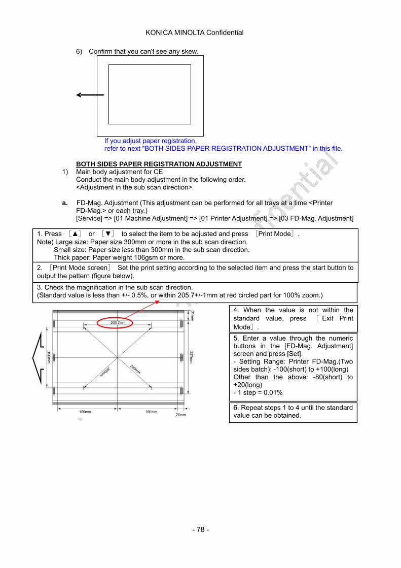
KONICA MINOLTA Confidential
6) Confirm that you can't see any skew.
If you adjust paper registration, refer to next "BOTH SIDES PAPER REGISTRATION ADJUSTMENT" in this file. BOTH SIDES PAPER REGISTRATION ADJUSTMENT
1) Main body adjustment for CE Conduct the main body adjustment in the following order. <Adjustment in the sub scan direction>
a. FD-Mag. Adjustment (This adjustment can be performed for all trays at a time <Printer FD-Mag.> or each tray.)
[Service] => [01 Machine Adjustment] => [01 Printer Adjustment] => [03 FD-Mag. Adjustment]
1. Press [▲] or [▼] to select the item to be adjusted and press [Print Mode]. Note) Large size: Paper size 300mm or more in the sub scan direction. Small size: Paper size less than 300mm in the sub scan direction. Thick paper: Paper weight 106gsm or more.
2. [Print Mode screen] Set the print setting according to the selected item and press the start button to output the pattern (figure below).
3. Check the magnification in the sub scan direction. (Standard value is less than +/- 0.5%, or within 205.7+/-1mm at red circled part for 100% zoom.)
4. When the value is not within the standard value, press [ Exit Print Mode].
5. Enter a value through the numeric buttons in the [FD-Mag. Adjustment] screen and press [Set]. - Setting Range: Printer FD-Mag.(Two sides batch): -100(short) to +100(long) Other than the above: -80(short) to +20(long) - 1 step = 0.01%
6. Repeat steps 1 to 4 until the standard value can be obtained.
- 78 -

KONICA MINOLTA Confidential
b. Restart Timing Adjustment (This adjustment is available for each paper tray, paper size and paper type respectively.) [Service] => [01 Machine Adjustment] => [01 Printer Adjustment] => [01 Restart Timing Adjustment]
6. Repeat steps 1 to 5 until the standard value can be obtained.
5. Enter a value through the numeric buttons in the [Restart timing Adjustment] screen and press [Set].
4. When the value is not within the standard value, press [Exit Print Mode].
3. Check the restart timing. (Standard value: Red circled part is 20+/-0.5mm)
1. ”01 Print out the pattern (figure below) referring the step 1 to 2 in the i) FD-Mag. Adjustment.
- Setting Range: 60 (short) to +60 (long) - 1 step = 0.1mm
<Adjustment in the main scan direction>
c. CD-Mag. Adjustment (This adjustment can be performed for all trays <Printer CD-Mag.> at a time or each tray.) [Service] => [01 Machine Adjustment] => [01 Printer Adjustment] => [03 CD-Mag. Adjustment]
2. Check the magnification in the main scan direction. ( Standard value is less than +/- 0.5%, or within 190+/-1mm at red circled part for 100% zoom.)
3. When the value is not within the standard value, press [Exit Print Mode].
1. ”01 Print out the pattern (figure below) referring the step 1 to 2 in the i) FD-Mag. Adjustment.
4. Enter a value through the numeric buttons in the [FD-Mag. Adjustment] screen and press [Set]. - Setting Range: 100(short) to +100(long) -1 step = 0.01% 5. Repeat steps 1 to 4 until the standard value can be obtained.
- 79 -
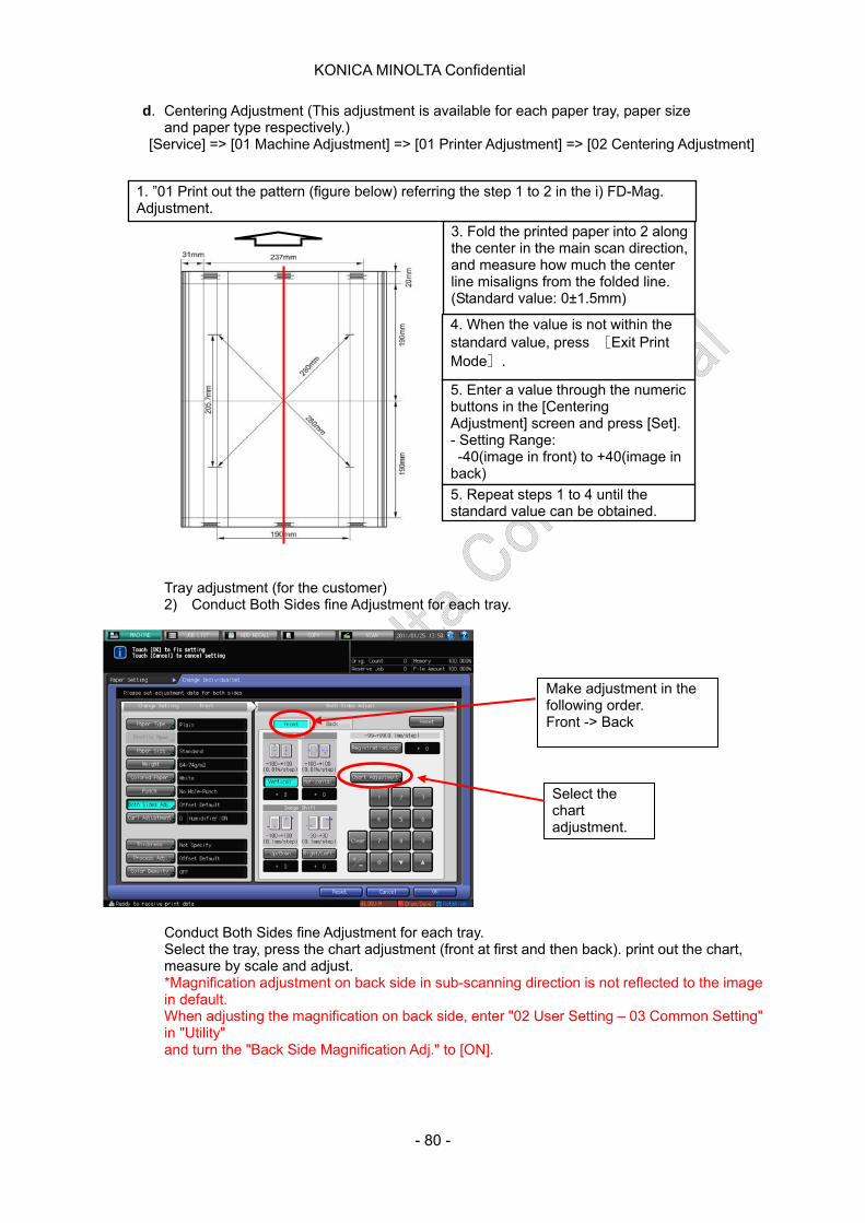
KONICA MINOLTA Confidential
d. Centering Adjustment (This adjustment is available for each paper tray, paper size and paper type respectively.)
[Service] => [01 Machine Adjustment] => [01 Printer Adjustment] => [02 Centering Adjustment]
Tray adjustment (for the customer) 2) Conduct Both Sides fine Adjustment for each tray.
5. Enter a value through the numeric buttons in the [Centering Adjustment] screen and press [Set]. - Setting Range: -40(image in front) to +40(image in back)
4. When the value is not within the standard value, press [Exit Print Mode].
3. Fold the printed paper into 2 along the center in the main scan direction, and measure how much the center line misaligns from the folded line.
1. ”01 Print out the pattern (figure below) referring the step 1 to 2 in the i) FD-Mag. Adjustment.
(Standard value: 0±1.5mm)
5. Repeat steps 1 to 4 until the standard value can be obtained.
Select the chart adjustment.
Make adjustment in the following order. Front -> Back
Conduct Both Sides fine Adjustment for each tray. Select the tray, press the chart adjustment (front at first and then back). print out the chart, measure by scale and adjust. *Magnification adjustment on back side in sub-scanning direction is not reflected to the image in default. When adjusting the magnification on back side, enter "02 User Setting – 03 Common Setting" in "Utility" and turn the "Back Side Magnification Adj." to [ON].
- 80 -
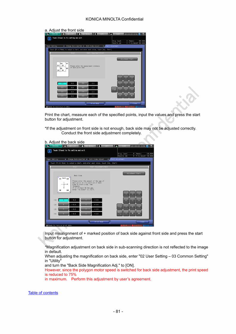
KONICA MINOLTA Confidential
a. Adjust the front side
Print the chart, measure each of the specified points, input the values and press the start button for adjustment.
*If the adjustment on front side is not enough, back side may not be adjusted correctly. Conduct the front side adjustment completely. b. Adjust the back side
Input misalignment of + marked position of back side against front side and press the start button for adjustment. *Magnification adjustment on back side in sub-scanning direction is not reflected to the image in default. When adjusting the magnification on back side, enter "02 User Setting – 03 Common Setting" in "Utility"
and turn the "Back Side Magnification Adj." to [ON]. However, since the polygon motor speed is switched for back side adjustment, the print speed
is reduced to 75% in maximum. Perform this adjustment by user’s agreement.
Table of contents
- 81 -
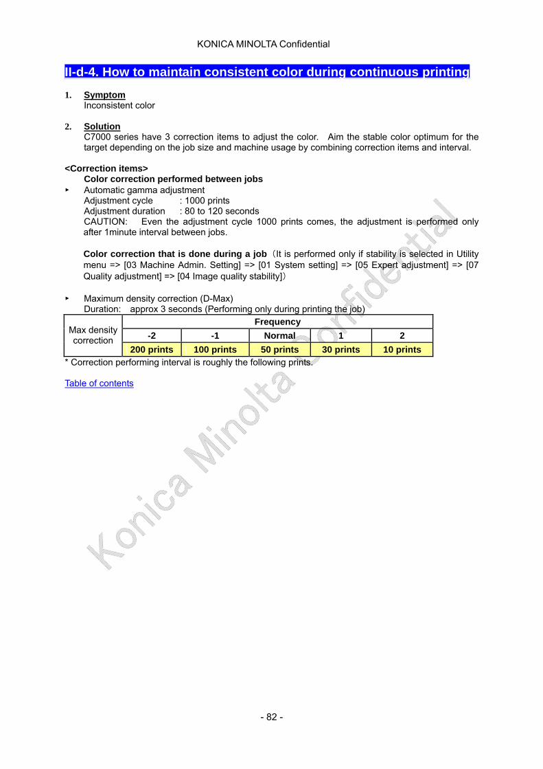
KONICA MINOLTA Confidential
II-d-4. How to maintain consistent color during continuous printing 1. Symptom
Inconsistent color 2. Solution
C7000 series have 3 correction items to adjust the color. Aim the stable color optimum for the target depending on the job size and machine usage by combining correction items and interval.
<Correction items>
Color correction performed between jobs ► Automatic gamma adjustment
Adjustment cycle : 1000 prints Adjustment duration : 80 to 120 seconds CAUTION: Even the adjustment cycle 1000 prints comes, the adjustment is performed only after 1minute interval between jobs.
Color correction that is done during a job (It is performed only if stability is selected in Utility menu => [03 Machine Admin. Setting] => [01 System setting] => [05 Expert adjustment] => [07 Quality adjustment] => [04 Image quality stability])
► Maximum density correction (D-Max)
Duration: approx 3 seconds (Performing only during printing the job) Frequency
-2 -1 Normal 1 2 Max density correction
200 prints 100 prints 50 prints 30 prints 10 prints * Correction performing interval is roughly the following prints. Table of contents
- 82 -

KONICA MINOLTA Confidential
III-a-1. PFU centering error (image suddenly shifts by 5mm) 1. Symptom
During continuous printing using Tray 4 and Tray 5, the image on the paper suddenly shifts by around 5 mm.
2. Cause
The centering sensor located at the PFU exit detects paper edge and calculates the off-center amount. For the correction, the image writing position is shifted according to the detected off-center amount to achieve high accuracy of the registration between side 1 and side 2. The off-center detection range is +/-5mm and if off-center amount exceeds the detection range, the centering correction mechanism cannot work. Consequently, the image suddenly shifts by around 5mm. The presumed causes are following 3. The cause differs by the problem occurrence paper side (side 1 or side2)
[CAUTION FOR THE CAUSE ANALYSIS]
・ Breakage of the sensor is cause in a few cases. Therefore please check if the sensor functions correctly.
・ For the 5mm shifts, the causes may be all of the 1, 2 and 3 or combination of two of them.
(If both side 1 and side 2 shift, all of them may affect)
i) Side guide is not set properly. Side guide is not set symmetrical from the center. There is a space between paper edge and side guide. To correct it refer to Both sides position adjustment/Paperfeedquideadjustment
ii) Main body and PFU connection was not adjusted properly at the installation.
The main body and PFU connection was not adjusted properly at the installation and the main body and PFU height is not correctly adjusted. To correct it, check the position of main body and PFU. If the adjustment is not enough, perform the adjustment as stated in next page.
ⅲ)Centering adjustment value (for Tray 4 and/or Tray 5) is wrong
Service mode => [01 Machine Adjustment] => [01 Printer Adjustment] => [02 Centering Adjustment]
- 83 -

KONICA MINOLTA Confidential
3. Solution i)Refer to “Centering error, skew (how to set paper in PFU)” ii) How to check the PFU and main body connection position
Check point 1
Positioning pin at front side
Positioning pin at rear side
Check point 2
Check point3
C
D B
A
The center of the holes on the front side panel and inner side panel should be concentric and the pin can be moved smoothly.
If the hole center position is different, adjust the caster height with the lever.
The center of the holes on the front side panel and inner side panel should be concentric and the pin can be moved smoothly.
If the hole center position is different, adjust the caster height with the lever.
Adjust until this gap becomes 3mm (optimum value)
The gap is less than 3mm => Lift up B The gap is larger than 3mm => Lift up A
*Height of C and D should be decided with the pin.
- 84 -

KONICA MINOLTA Confidential
iii) Centering adjustment value (for Tray 4 and/or Tray 5) is wrong To correct it, readjust the centering adjustment of “Tray 4” and “Tray 5”.
Service mode => [01 Machine Adjustment] => [01 Printer Adjustment] => [02 Centering Adjustment]: Print the pattern and measure the off-center amount with the sale.
[CAUTION FOR THE WORK] * For the “Tray 4”, “Tray 5” and “ADU” adjustment value, 50 and larger value cannot be entered. * During this adjustment, PFU centering sensor should be ON (default).
DipSW 26-4 (Printer auto centering correction PF ON: 0, OFF: 1) When the Printer auto centering correction sensor is set to OFF, sudden shift with 5mm will not occur but centering correction itself is not performed. Consequently, the registration accuracy between side 1 and side 2 may becomes poor. (Use this setting to check if the centering error is caused by sensor)
* Even if the main body and PF are connected properly, there may be the slight difference. Centering adjustment for Tray 4 and Tray 5 are to correct this difference.
After re-adjusting the centering error, exit service mode and perform side1/2 adjustment for each tray with the specific paper customer want to use. For details, refer to Both sides position adjustment/Tray adjustment.
Table of contents
- 85 -
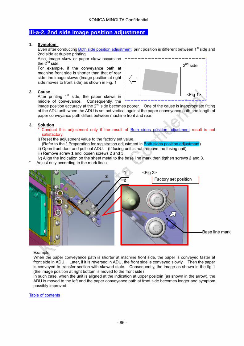
KONICA MINOLTA Confidential
2nd side
<Fig 1>
III-a-2. 2nd side image position adjustment 1. Symptom
Even after conducting Both side position adjustment, print position is different between 1st side and 2nd side at duplex printing. Also, image skew or paper skew occurs on the 2nd side. For example, if the conveyance path at machine front side is shorter than that of rear side, the image skews (Image position at right side moves to front side) as shown in Fig. 1
2. Cause
After printing 1st side, the paper skews in middle of conveyance. Consequently, the image position accuracy at the 2nd side becomes poorer. One of the cause is inappropriate fitting of the ADU unit: when the ADU is set not vertical against the paper conveyance path, the length of paper conveyance path differs between machine front and rear.
3. Solution
* Conduct this adjustment only if the result of Both sides position adjustment result is not satisfactory.
i) Reset the adjustment value to the factory set value. (Refer to the * Preparation for registration adjustment in Both sides position adjustment)
ii) Open front door and pull out ADU. (If fusing unit is hot, remove the fusing unit) iii) Remove screw 1 and loosen screws 2 and 3. iv) Align the indication on the sheet metal to the base line mark then tigthen screws 2 and 3.
* Adjust only according to the mark lines.
Factory set position 2
Base line mark
1 3
<Fig 2>
Example: When the paper conveyance path is shorter at machine front side, the paper is conveyed faster at front side in ADU. Later, if it is reversed in ADU, the front side is conveyed slowly. Then the paper is conveyed to transfer section with skewed state. Consequently, the image as shown in the fig 1 (the image position at right bottom is moved to the front side) In such case, when the unit is aligned at the indication at upper positoin (as shown in the arrow), the ADU is moved to the left and the paper conveyance path at front side becomes longer and symptom possibly improved.
Table of contents
- 86 -
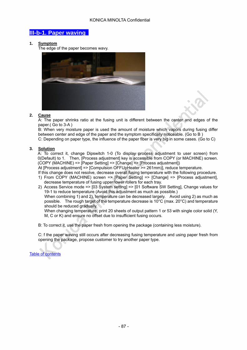
KONICA MINOLTA Confidential
III-b-1. Paper waving 1. Symptom
The edge of the paper becomes wavy.
2. Cause
A: The paper shrinks ratio at the fusing unit is different between the center and edges of the paper.( Go to 3-A ) B: When very moisture paper is used the amount of moisture which vapors during fusing differ between center and edge of the paper and the symptom specifically noticeable. (Go to B ) C: Depending on paper type, the influence of the paper fiber is very big in some cases. (Go to C)
3. Solution
A: To correct it, change Dipswitch 1-0 (To display process adjustment to user screen) from 0(Default) to 1. Then, [Process adjustment] key is accessible from COPY (or MACHINE) screen. (COPY (MACHINE) => [Paper Setting] => [Change] => [Process adjustment]) At [Process adjustment] => [Compulsion OFFUpHeater >= 261mm)], reduce temperature. If this change does not resolve, decrease overall fusing temperature with the following procedure. 1) From COPY (MACHINE) screen => [Paper Setting] => [Change] => [Process adjustment],
decrease temperature of fusing upper/lower rollers for each tray. 2) Access Service mode => [03 System setting] => [01 Software SW Setting], Change values for
19-1 to reduce temperature (Avoid this adjustment as much as possible.) When combining 1) and 2), temperature can be decreased largely. Avoid using 2) as much as possible. The rough target of the temperature decrease is 10°C (max. 20°C) and temperature should be reduced gradually. When changing temperature, print 20 sheets of output pattern 1 or 53 with single color solid (Y, M, C or K) and ensure no offset due to insufficient fusing occurs.
B: To correct it, use the paper fresh from opening the package (containing less moisture). C: f the paper waving still occurs after decreasing fusing temperature and using paper fresh from opening the package, propose customer to try another paper type.
Table of contents
- 87 -

KONICA MINOLTA Confidential
III-b-2. Curl or backling at fusing unit 1. Symptom
A curl like pressing mark by the roller or buckling occurs in fusing unit. (See following photo). The curl/buckling occurs irregularly and sometimes more than once in a sheet. The symptom tends to occur more when using thin sheet.
2. Cause
When the Teflon tape which is attached to fusing separation plate and the paper rubs with each other, the edge of the Teflon tape gets worn and the steel plate of the separation plate or adhesive side of the tape is exposed. When the above occurs, the friction between paper and the separation plate increases and the paper feed is fed rather unstably. Consequently, the paper warps during conveyance and concave curl/buckling occurs.
(Adhesive tape face exposed at the exit side of the Teflon tape)
3. Solution Replace fusing separation plate assembly. If the similar symptom occurs on C6500 series / C5500 series, be sure to use the C7000 parts. Part name: Fusing separation assembly Part number: A1DUR74H00
b) How to replace fusing separation plate ii) Remove fusing unit cover iii) Remove fusing cover /Rr
Note: When re-installing the plate, rotate the knob to the counterclockwise direction to release the pressure.
iv) Open fusing paper exit plate Assy and rotate the knob to counterclockwise direction. Press the fusing roller
- 88 -

KONICA MINOLTA Confidential
v) Loosen screw [1] (See the photo at right)
vi) Remove spring [1] at 2 positions, then remove the fusing sepratio plate Assy [2] to arrowed direction. (See photo at bottom left) Caution: When fitting the spring, be sure to use the spring hook tool. Note: When installing fusing separation plate Assy [3], confirm that it contact with plate [4]
(right figure).
vii) Re-install the unit in the reverse course of removal procedure. viii) After fusing separation plate Assy replacement, clear the fixed parts counter No. 136 (For
C7000/C6000 series only)
Table of contents
- 89 -
KONICA MINOLTA Confidential
IV-a-1. Printer gamma offset automatic adjustment does not complete normally after trying several times. 1. Symptom
Though performing Printer gamma offset automatic adjustment, it does not success: Service mode [01. Machine Adjustment] => [03 Quality Adjustment] => [01 Printer Gamma Adjustment] => [02 Printer Gamma Offset Auto].
2. Cause Some of image cannot be adjusted with printer gamma offset automatic adjustment if it is outside of adjustment range.
3. Solution The maximum number to repeat Printer gamma offset auto adjustment should be 5 times. If the adjustment does not complete normally, perform Printer gamma offset adjustment instead. Perform [Printer Gamma Offset Adjustment] only for the screen failed to adjust with the automatic adjustment in 5 screens.
Table of contents
- 90 -
KONICA MINOLTA Confidential
IV-a-2. Print job is not accepted while machine indicates dehumidifying
1. Symptom
The machine indicates dehumidifying and print job is not accepted for a while. Optional HT-50X is equipped.
2. Cause
When dehumidifier heater is installed to the tray to enhance coated paper feeding ability under high humidity environment (humidity is 56% or over), printing is not accepted until the sensor in the tray detects certain temperature with the default setting. For example, even dehumidifying completes once then the tray is pulled out, “dehumidifying” is displayed.
3. Solution
Change the setting of DipSW18-4 Print during temperature control by dehumidifier heater from 0: Prohibited => Allowed The machine receive print job even during the warming up of dehumidifier heater.
CAUTION
* Since dehumidifying operation does not complete, no feed jam of the coated paper under high humidity tends to occur.
* Even under high humidity environment, no feed occurs mostly on coated paper. Therefore, dehumifying is performed only for coated paper.
Table of contents
- 91 -
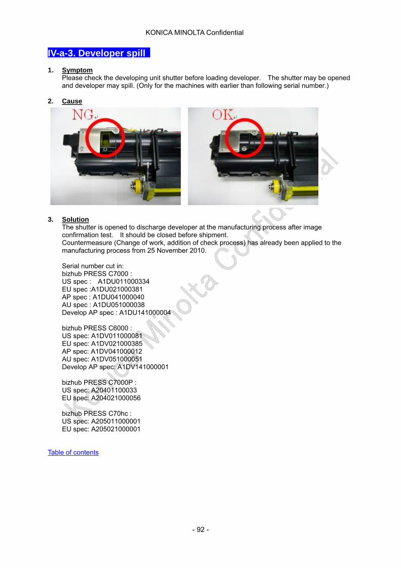
KONICA MINOLTA Confidential
IV-a-3. Developer spill 1. Symptom
Please check the developing unit shutter before loading developer. The shutter may be opened and developer may spill. (Only for the machines with earlier than following serial number.)
2. Cause
3. Solution
The shutter is opened to discharge developer at the manufacturing process after image confirmation test. It should be closed before shipment. Countermeasure (Change of work, addition of check process) has already been applied to the manufacturing process from 25 November 2010.
Serial number cut in: bizhub PRESS C7000 : US spec : A1DU011000334 EU spec :A1DU021000381 AP spec : A1DU041000040 AU spec : A1DU051000038 Develop AP spec : A1DU141000004
bizhub PRESS C6000 : US spec: A1DV011000081 EU spec: A1DV021000385 AP spec: A1DV041000012 AU spec: A1DV051000051 Develop AP spec: A1DV141000001
bizhub PRESS C7000P : US spec: A20401100033 EU spec: A204021000056
bizhub PRESS C70hc : US spec: A205011000001 EU spec: A205021000001
Table of contents
- 92 -

KONICA MINOLTA Confidential
IV-a-4. Either error code 246 or 247 is indicated on the display with ISW 1. Symptom
Either error code 246 or 247 is indicated on the display with ISW When rewriting C-ROM with ISW, Either error code 246 or 247 is indicated on the display.
2. Cause Firmware version may not be correct.
3. Solution Turn OFF/ON the sub-switch. Check the C-ROM version [ Service mode -> 08 Firmware version ]. Please reload the correct firmware version.
If the firmware is not pre-installed, check the serial number of Printer control board. Please refer this TNI TNBT1100104EN*
The correct combination of firmware version and file name is as follows.
Version name [A1DU0Y0-00C1-G00-] -> File name [A1DU0Y0-00C1-G00-] Version name [A1DU0Y0-00C1-G80-] -> File name [A1DU0Y0-00C1-G80-] Version name [A1DU0Y0-00C1-G81-] -> File name [A1DU0Y0-00C1-G81-]
Table of contents
- 93 -

KONICA MINOLTA Confidential
IV-a-5. ISW does not complete 1. Symptom
When rewriting C-ROM with ISW, the machine's downloading is maintained more than 2 minutes.
2. Cause Firmware version may not be correct.
3. Solution Turn OFF/ON the sub-switch. Check the C-ROM version [ Service mode -> 08 Firmware version ]. Please reload the correct firmware version. If the firmware is not pre-installed, check the serial number of Printer control board. Please refer this TNI TNBT1100104EN* The correct combination of firmware version and file name is as follows. Version name [A1DU0Y0-00C1-G00-] -> File name [A1DU0Y0-00C1-G00-] Version name [A1DU0Y0-00C1-G80-] -> File name [A1DU0Y0-00C1-G80-] Version name [A1DU0Y0-00C1-G81-] -> File name [A1DU0Y0-00C1-G81-]
Table of contents
- 94 -
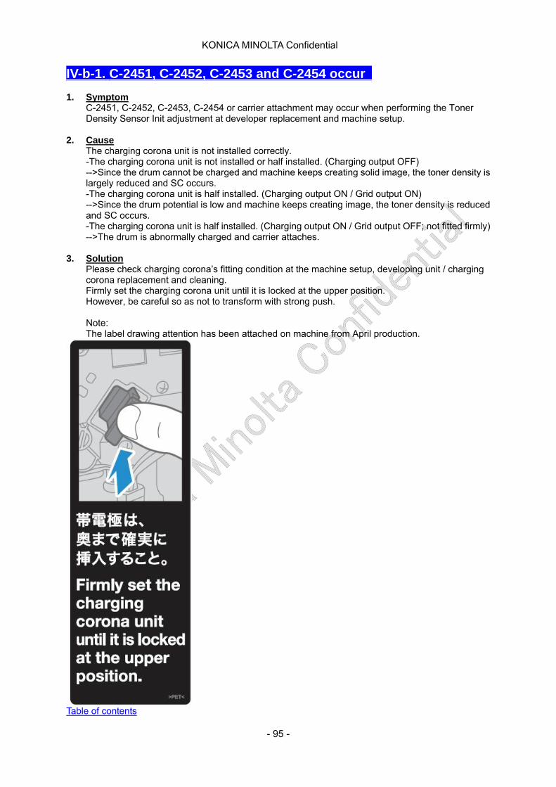
KONICA MINOLTA Confidential
IV-b-1. C-2451, C-2452, C-2453 and C-2454 occur 1. Symptom
C-2451, C-2452, C-2453, C-2454 or carrier attachment may occur when performing the Toner Density Sensor Init adjustment at developer replacement and machine setup.
2. Cause The charging corona unit is not installed correctly. -The charging corona unit is not installed or half installed. (Charging output OFF) -->Since the drum cannot be charged and machine keeps creating solid image, the toner density is largely reduced and SC occurs. -The charging corona unit is half installed. (Charging output ON / Grid output ON) -->Since the drum potential is low and machine keeps creating image, the toner density is reduced and SC occurs. -The charging corona unit is half installed. (Charging output ON / Grid output OFF; not fitted firmly) -->The drum is abnormally charged and carrier attaches.
3. Solution
Please check charging corona’s fitting condition at the machine setup, developing unit / charging corona replacement and cleaning. Firmly set the charging corona unit until it is locked at the upper position. However, be careful so as not to transform with strong push.
Note: The label drawing attention has been attached on machine from April production.
Table of contents
- 95 -
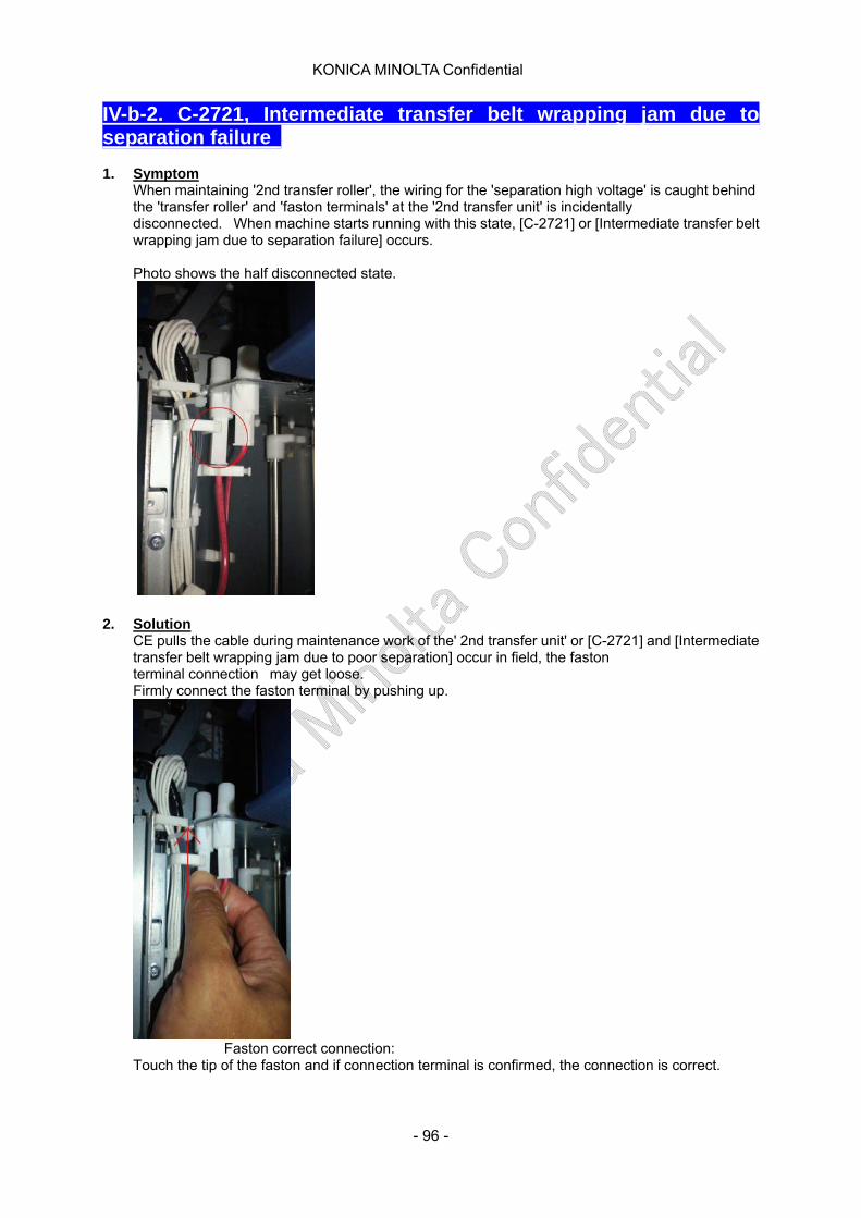
KONICA MINOLTA Confidential
IV-b-2. C-2721, Intermediate transfer belt wrapping jam due to separation failure 1. Symptom
When maintaining '2nd transfer roller', the wiring for the 'separation high voltage' is caught behind the 'transfer roller' and 'faston terminals' at the '2nd transfer unit' is incidentally disconnected. When machine starts running with this state, [C-2721] or [Intermediate transfer belt wrapping jam due to separation failure] occurs.
Photo shows the half disconnected state.
2. Solution CE pulls the cable during maintenance work of the' 2nd transfer unit' or [C-2721] and [Intermediate transfer belt wrapping jam due to poor separation] occur in field, the faston terminal connection may get loose. Firmly connect the faston terminal by pushing up.
Faston correct connection:
Touch the tip of the faston and if connection terminal is confirmed, the connection is correct.
- 96 -

KONICA MINOLTA Confidential
Table of contents
- 97 -

KONICA MINOLTA Confidential
IV-b-3. C-C101 occurs right after turning ON the power source 1. Symptom
C-C101 occurs right after turning ON the power source
2. Cause As opening/closing the door, the wiring at the vertical conveyance section was separated and contacted to the metal edge, which broke the wiring's cover and caused earth fault, and then ICP23 of the printer control board was brown.
3. Solution Wind the wiring with the tape so that the wiring is not separated. See the figure below.
- 98 -
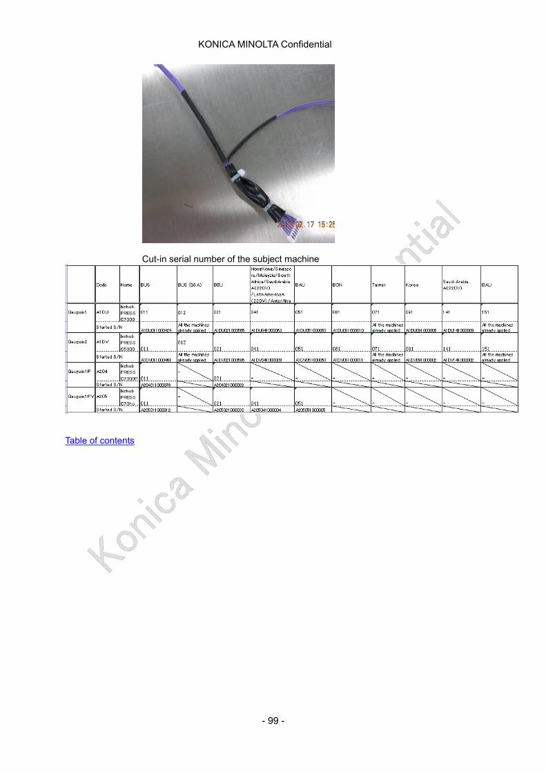
KONICA MINOLTA Confidential
Cut-in serial number of the subject machine
Table of contents
- 99 -
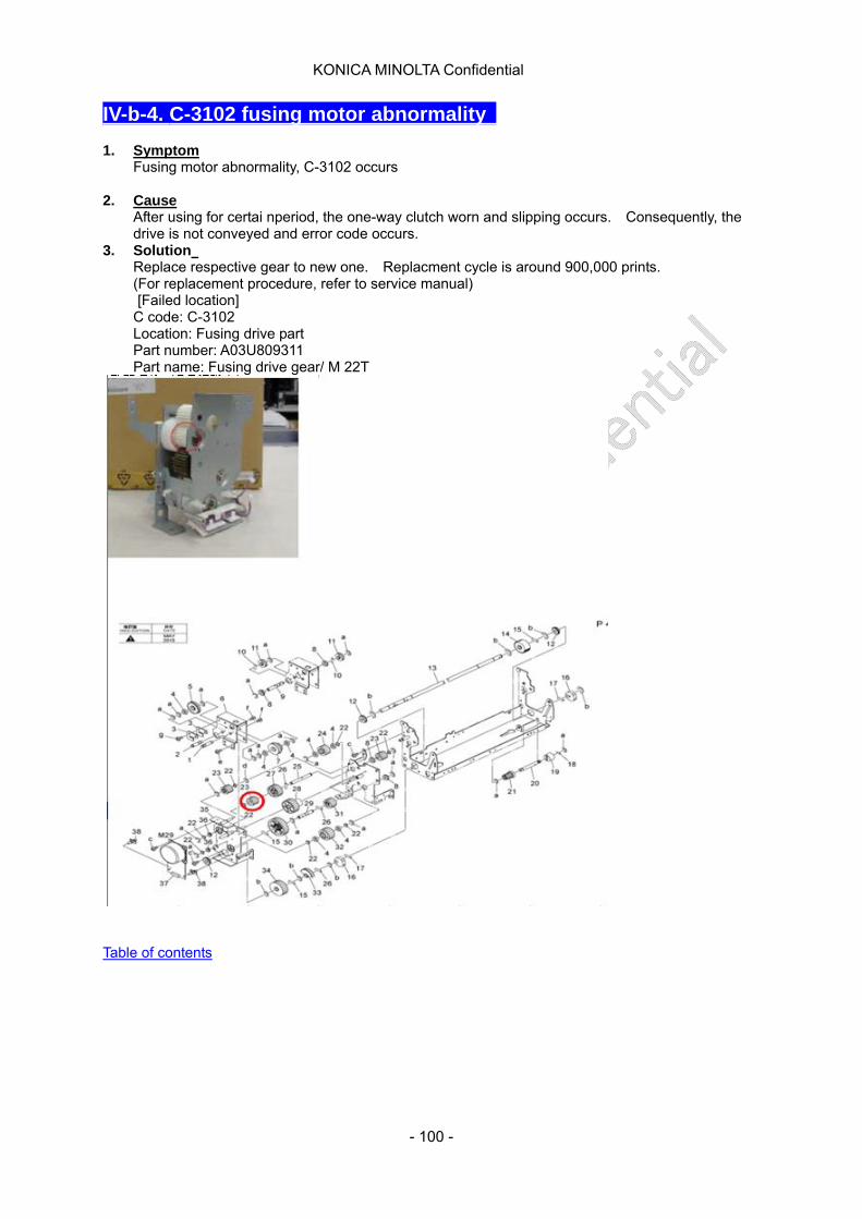
KONICA MINOLTA Confidential
IV-b-4. C-3102 fusing motor abnormality 1. Symptom
Fusing motor abnormality, C-3102 occurs 2. Cause
After using for certai nperiod, the one-way clutch worn and slipping occurs. Consequently, the drive is not conveyed and error code occurs.
3. Solution Replace respective gear to new one. Replacment cycle is around 900,000 prints. (For replacement procedure, refer to service manual) [Failed location]
C code: C-3102 Location: Fusing drive part Part number: A03U809311 Part name: Fusing drive gear/ M 22T
Table of contents
- 100 -
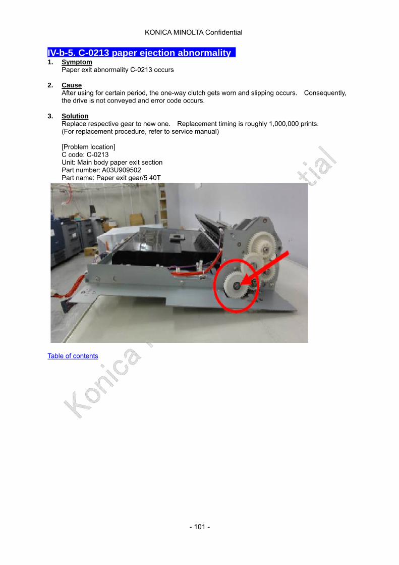
KONICA MINOLTA Confidential
IV-b-5. C-0213 paper ejection abnormality 1. Symptom
Paper exit abnormality C-0213 occurs 2. Cause
After using for certain period, the one-way clutch gets worn and slipping occurs. Consequently, the drive is not conveyed and error code occurs.
3. Solution
Replace respective gear to new one. Replacement timing is roughly 1,000,000 prints. (For replacement procedure, refer to service manual) [Problem location] C code: C-0213 Unit: Main body paper exit section Part number: A03U909502 Part name: Paper exit gear/5 40T
Table of contents
- 101 -
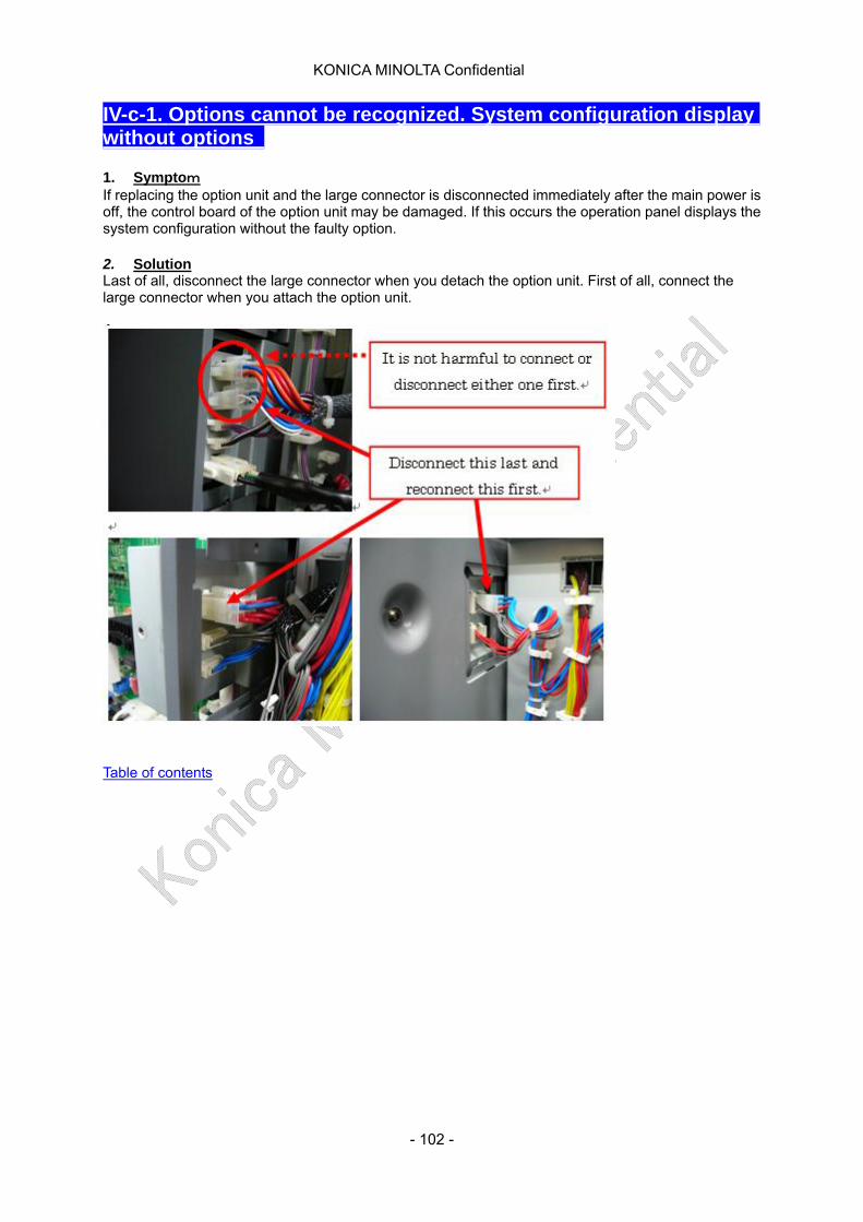
KONICA MINOLTA Confidential
IV-c-1. Options cannot be recognized. System configuration display without options
1. Symptom If replacing the option unit and the large connector is disconnected immediately after the main power is off, the control board of the option unit may be damaged. If this occurs the operation panel displays the system configuration without the faulty option. 2. Solution Last of all, disconnect the large connector when you detach the option unit. First of all, connect the large connector when you attach the option unit.
Table of contents
- 102 -
KONICA MINOLTA Confidential
IV-c-2. Caution for charging developer to developing unit 1. Symptom
Please check if there is any foreign material on the developer charging funnel before loading developer
2. Solution Foreign material (the burr of plastic, glue trash, etc.) may stick to Developer Charging funnel. If the foreign material stick on Developer Charging funnel mixes in the developer, abnormal image (white streaks) may appear.
Before charging developer, please check the Developer Charging funnel and remove the foreign material if any.
Table of contents
- 103 -
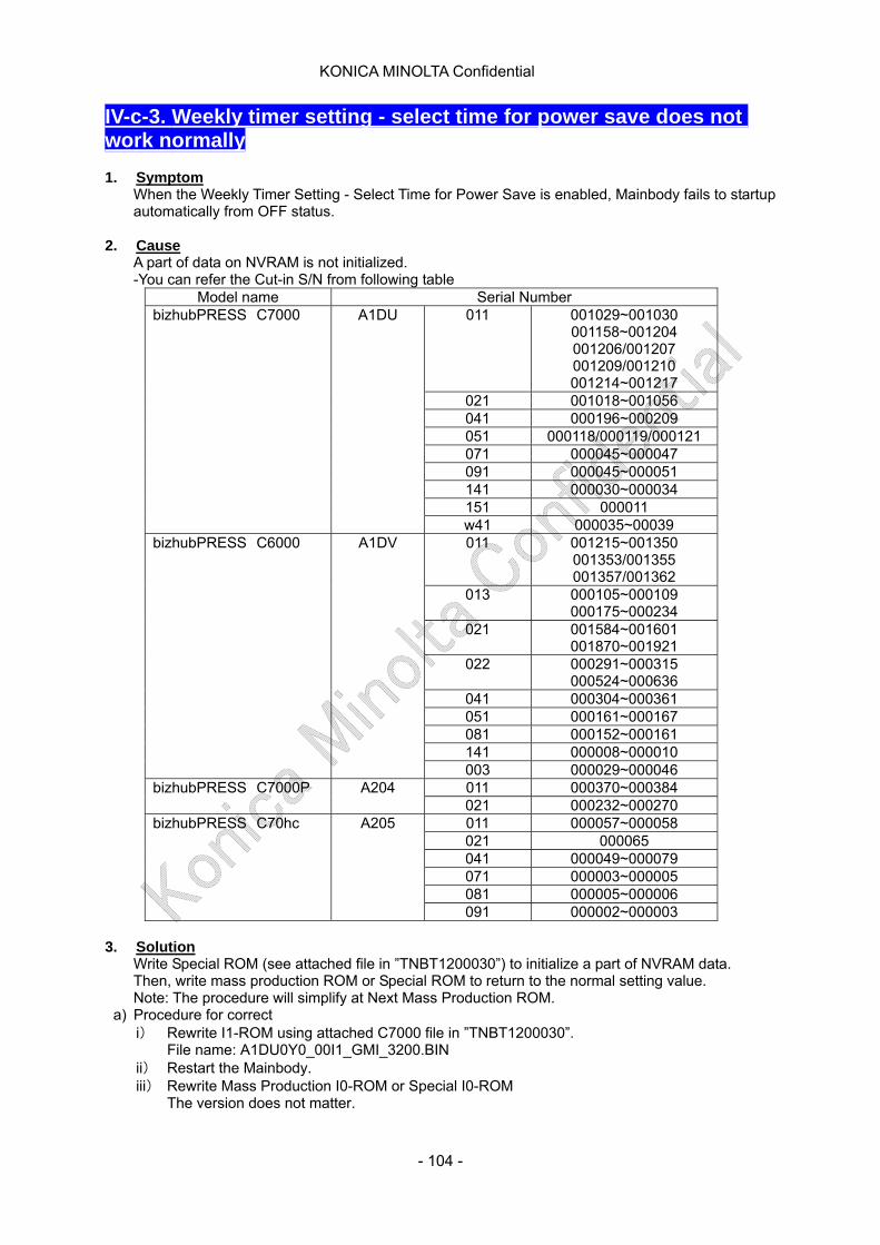
KONICA MINOLTA Confidential
IV-c-3. Weekly timer setting - select time for power save does not work normally 1. Symptom
When the Weekly Timer Setting - Select Time for Power Save is enabled, Mainbody fails to startup automatically from OFF status.
2. Cause A part of data on NVRAM is not initialized. -You can refer the Cut-in S/N from following table
Model name Serial Number 011 001029~001030
001158~001204 001206/001207 001209/001210 001214~001217
021 001018~001056 041 000196~000209 051 000118/000119/000121 071 000045~000047 091 000045~000051 141 000030~000034 151 000011
bizhubPRESS C7000 A1DU
w41 000035~00039 011 001215~001350
001353/001355 001357/001362
013 000105~000109 000175~000234
021 001584~001601 001870~001921
022 000291~000315 000524~000636
041 000304~000361 051 000161~000167 081 000152~000161 141 000008~000010
bizhubPRESS C6000 A1DV
003 000029~000046 011 000370~000384 bizhubPRESS C7000P A204 021 000232~000270 011 000057~000058 021 000065 041 000049~000079 071 000003~000005 081 000005~000006
bizhubPRESS C70hc A205
091 000002~000003
3. Solution Write Special ROM (see attached file in ”TNBT1200030”) to initialize a part of NVRAM data. Then, write mass production ROM or Special ROM to return to the normal setting value. Note: The procedure will simplify at Next Mass Production ROM.
a) Procedure for correct i) Rewrite I1-ROM using attached C7000 file in ”TNBT1200030”.
File name: A1DU0Y0_00I1_GMI_3200.BIN ii) Restart the Mainbody. iii) Rewrite Mass Production I0-ROM or Special I0-ROM
The version does not matter.
- 104 -
KONICA MINOLTA Confidential
The latest ROM and its DL (As of Mar 23, 2012) Mass production I0-ROM DLBT1101604
b) The procedure for system checking i) Press [Utility]->[Administrator Setting]->[System Setting]->[Weekly Timer Setting]->[01
Weekly Timer ON/OFF Setting]. Select [Weekly Timer ON].
ii) In [02 Time Setting], [03 Date Setting], set Timer to the date of system checking. iii) Setting "OFF", "Restart" in [04 Select Time for Power Save]
"OFF", "Restart" needs to be set between time of timer ON and time of timer OFF. iv) If the mainbody starts automatically at the time of "Restart", It would be success.
If not automatically started up, try the correction procedure all over again. v) Select [Weekly Timer OFF] in [01 Weekly Timer ON/OFF Setting] after system checking.
Table of contents
- 105 -
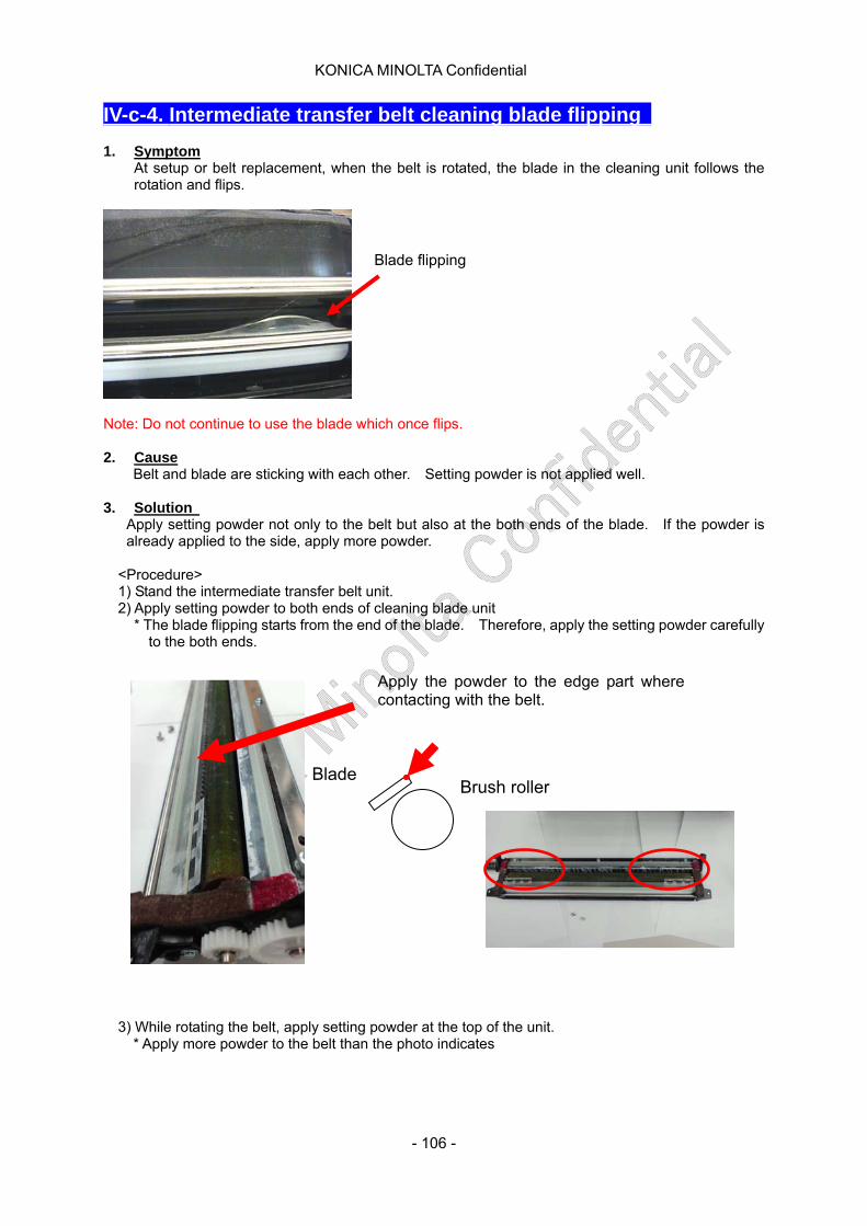
KONICA MINOLTA Confidential
IV-c-4. Intermediate transfer belt cleaning blade flipping 1. Symptom
At setup or belt replacement, when the belt is rotated, the blade in the cleaning unit follows the rotation and flips.
Blade flipping
Note: Do not continue to use the blade which once flips. 2. Cause
Belt and blade are sticking with each other. Setting powder is not applied well. 3. Solution
Apply setting powder not only to the belt but also at the both ends of the blade. If the powder is already applied to the side, apply more powder.
<Procedure> 1) Stand the intermediate transfer belt unit. 2) Apply setting powder to both ends of cleaning blade unit
* The blade flipping starts from the end of the blade. Therefore, apply the setting powder carefully to the both ends.
3) While rotating the belt, apply setting powder at the top of the unit.
* Apply more powder to the belt than the photo indicates
Blade
Apply the powder to the edge part where contacting with the belt.
Brush roller
- 106 -

KONICA MINOLTA Confidential
4) After applying powder to the half area of the whole belt, rotate belt until the powder applied part
reaches to the cleaner attaching part. 5) Attach cleaner unit to the intermediate transfer belt unit. 6) Rotate the belt until powder applied part disappear. 6) Install intermediate transfer belt unit to the machine. * Note: Do not continue to use the blade which once flips.
Table of contents
- 107 -
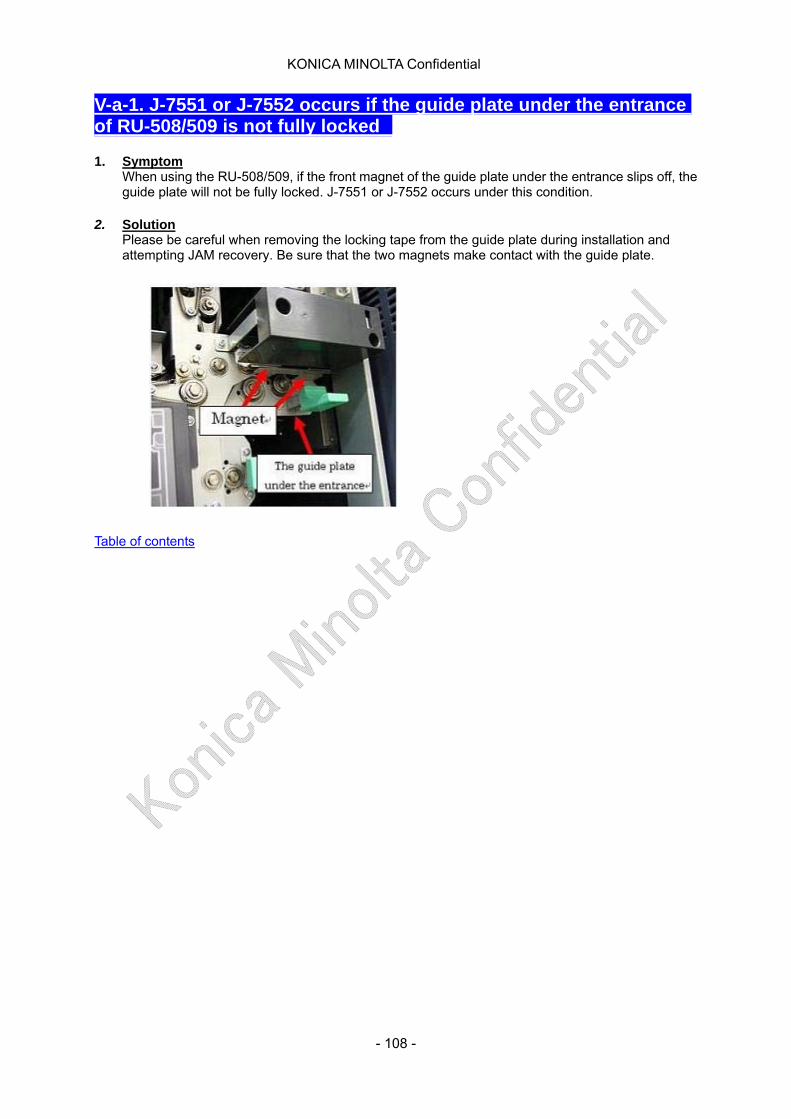
KONICA MINOLTA Confidential
V-a-1. J-7551 or J-7552 occurs if the guide plate under the entrance of RU-508/509 is not fully locked 1. Symptom
When using the RU-508/509, if the front magnet of the guide plate under the entrance slips off, the guide plate will not be fully locked. J-7551 or J-7552 occurs under this condition.
2. Solution
Please be careful when removing the locking tape from the guide plate during installation and attempting JAM recovery. Be sure that the two magnets make contact with the guide plate.
Table of contents
- 108 -
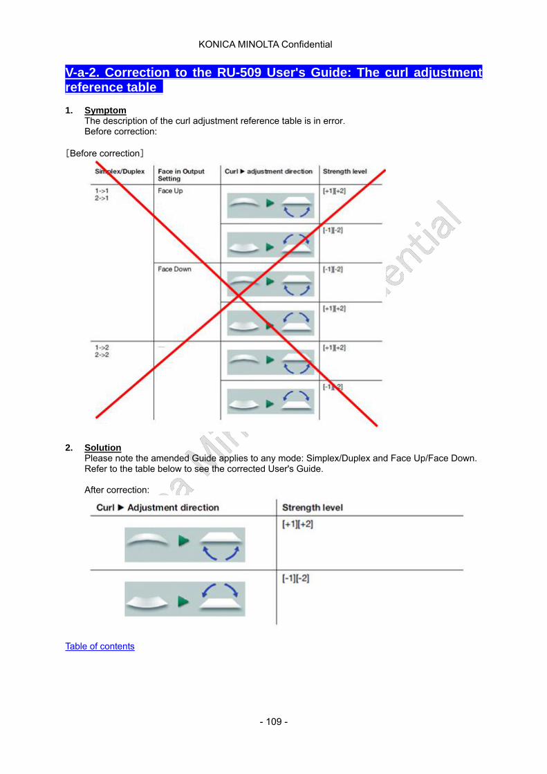
KONICA MINOLTA Confidential
V-a-2. Correction to the RU-509 User's Guide: The curl adjustment reference table 1. Symptom
The description of the curl adjustment reference table is in error. Before correction:
[Before correction]
2. Solution
Please note the amended Guide applies to any mode: Simplex/Duplex and Face Up/Face Down. Refer to the table below to see the corrected User's Guide.
After correction:
Table of contents
- 109 -

KONICA MINOLTA Confidential
V-a-3. Water leakage of HM-101/102 1. Symptom
If you overfill the water tank, leakage might occur. 2. Solution
Please fill to the limit line shown on the seal on the front of the tank.
Table of contents
- 110 -
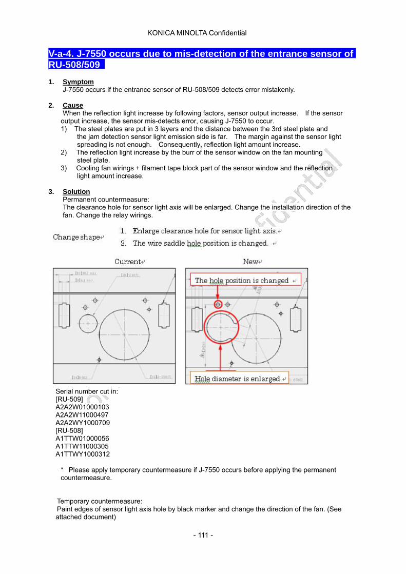
KONICA MINOLTA Confidential
V-a-4. J-7550 occurs due to mis-detection of the entrance sensor of RU-508/509 1. Symptom
J-7550 occurs if the entrance sensor of RU-508/509 detects error mistakenly.
2. Cause When the reflection light increase by following factors, sensor output increase. If the sensor
output increase, the sensor mis-detects error, causing J-7550 to occur. 1) The steel plates are put in 3 layers and the distance between the 3rd steel plate and the jam detection sensor light emission side is far. The margin against the sensor light spreading is not enough. Consequently, reflection light amount increase. 2) The reflection light increase by the burr of the sensor window on the fan mounting steel plate.
3) Cooling fan wirings + filament tape block part of the sensor window and the reflection light amount increase.
3. Solution
Permanent countermeasure: The clearance hole for sensor light axis will be enlarged. Change the installation direction of the fan. Change the relay wirings.
Serial number cut in: [RU-509] A2A2W01000103 A2A2W11000497 A2A2WY1000709 [RU-508] A1TTW01000056 A1TTW11000305 A1TTWY1000312
* Please apply temporary countermeasure if J-7550 occurs before applying the permanent
countermeasure.
Temporary countermeasure: Paint edges of sensor light axis hole by black marker and change the direction of the fan. (See attached document)
- 111 -
KONICA MINOLTA Confidential
Serial number cut in: [RU-509] A2A2W01000055 A2A2W11000314 A2A2WY1000429 [RU-508] A1TTW01000041 A1TTW11000163 A1TTWY1000149
Table of contents
- 112 -

KONICA MINOLTA Confidential
V-a-5. Adjustment for scratch on thick paper 1. Symptom
Scratch occurs parallel against the paper feed direction (sub scan direction).
2. Cause a) RU-509
- Scratch occurs at 50 to 65 mm from paper center caused by the guide plate/11 (No:A1TT703512). - During conveying paper, image surface is scratched (Location of problem part cannot be specified.) Image scratch occurs frequently for various parts during paper feed. (where to occur is hard to specify.) The countermeasure has not been applied to the machine with S/N earlier than the list below. It is necessary to apply the countermeasure appropriately.
Countermeasure Contents of measure Old parts New parts Parts name
A1TT7035-01B A1TT7035-12C Guide plate /11
A1TT7148-00A Abolish Guide sheet /O
A1TT7149-00A Abolish Guide sheet /P Go to No. I Abolish the PET for B6S JAM
countermeasure
A1TT7151-00A Abolish Auxiliary
Go to No. II Change the width of the winding prevention PET (12 -> 8mm)
A1TT7137-00A A1TT7153-00A Guide Sheet /R
A1TT5013-00A A1TT5013-11B Conveyance board /3
A1TT5112-00A A1TT5112-11B Mount board /Ft
A1TT5113-00A A1TT5113-11B Mount board /Rr Go to No. III
Strengthen the lower conveyance open close guide plate. (widen the space of conveying path)
New 04864526-0DA Stopper rubber
Go to No. IV
Lower the backup roller at the color sensor section by 0.25mm. (widen the space of conveying path)
New A1TT7154-00A Spacer/2
- 113 -
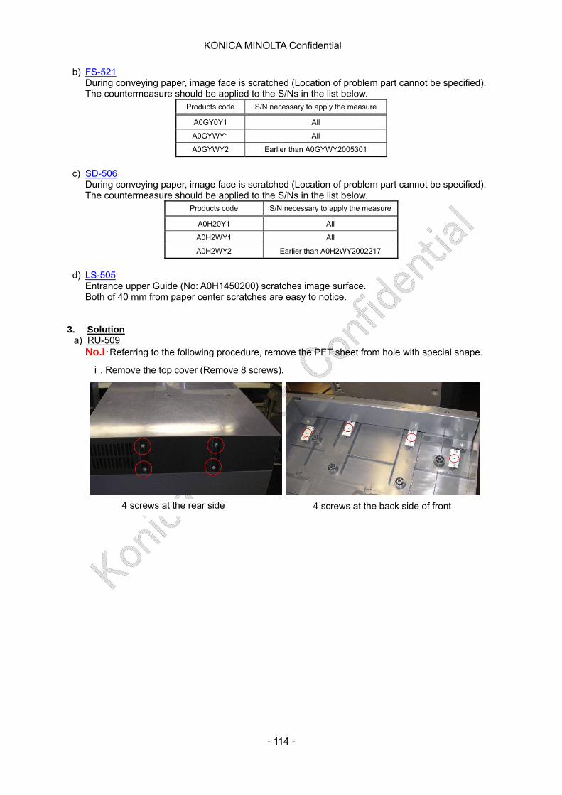
KONICA MINOLTA Confidential
b) FS-521 During conveying paper, image face is scratched (Location of problem part cannot be specified). The countermeasure should be applied to the S/Ns in the list below.
Products code S/N necessary to apply the measure
A0GY0Y1 All
A0GYWY1 All
A0GYWY2 Earlier than A0GYWY2005301
c) SD-506
During conveying paper, image face is scratched (Location of problem part cannot be specified). The countermeasure should be applied to the S/Ns in the list below.
Products code S/N necessary to apply the measure
A0H20Y1 All
A0H2WY1 All
A0H2WY2 Earlier than A0H2WY2002217
d) LS-505
Entrance upper Guide (No: A0H1450200) scratches image surface. Both of 40 mm from paper center scratches are easy to notice.
3. Solution
a) RU-509 No.I:Referring to the following procedure, remove the PET sheet from hole with special shape.
ⅰ. Remove the top cover (Remove 8 screws).
4 screws at the back side of front 4 screws at the rear side
- 114 -
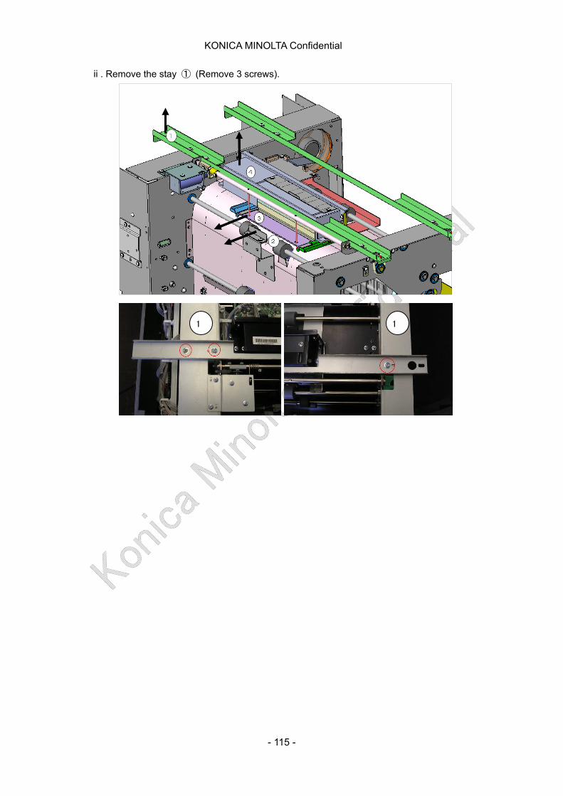
KONICA MINOLTA Confidential
ⅱ. Remove the stay ① (Remove 3 screws).
1 1
- 115 -
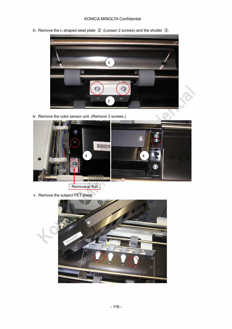
KONICA MINOLTA Confidential
ⅲ. Remove the L-shaped steel plate ② (Loosen 2 screws) and the shutter ③.
3
2
ⅳ. Remove the color sensor unit. (Remove 3 screws.)
Remove at first
4 4
ⅴ. Remove the subject PET sheet.
- 116 -

KONICA MINOLTA Confidential
No.II:Referring to the following procedure, remove the existing PET sheet (No:A1TT7137) and attach new PET sheet (No:A1TTP703).
ⅶ. Remove the two springs at HM entrance guide plate.
ⅵ.Remove the door stopper.
Tension Spring
HM entrance guide plate
ⅷ. Remove the HM entrance guide plate. ・Remove the fulcrum shaft plate by 1 screw. ・Remove the HM entrance guide plate.
HM entrance guide plate
Fulcrum shaft plate
- 117 -

KONICA MINOLTA Confidential
ⅸ. Replace the PET ・Remove the old one (12mm). ・Attach new one (8mm). Datum line: Gap between Roller is less than 1mm. DO NOT TOUCH TO ROLLER.
A1TT7155 (Guide Sheet /T)
Remove the old one (12mm) and attach new one (8mm)
- 118 -
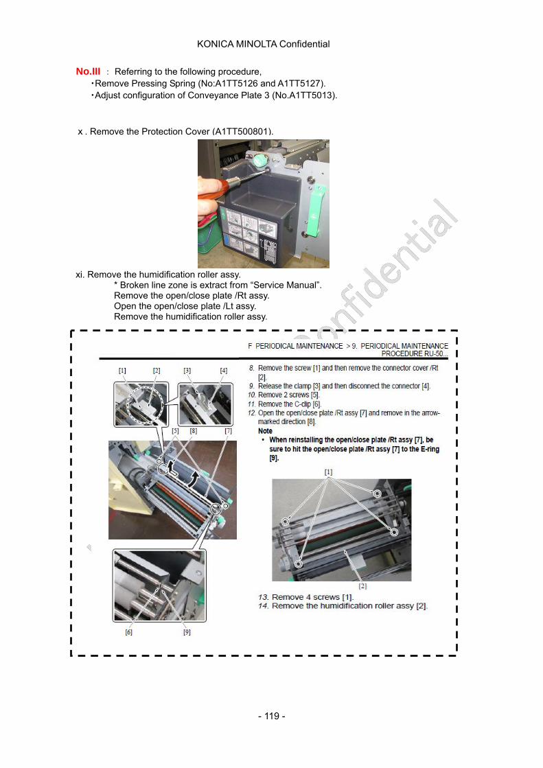
KONICA MINOLTA Confidential
No.III : Referring to the following procedure, ・Remove Pressing Spring (No:A1TT5126 and A1TT5127). ・Adjust configuration of Conveyance Plate 3 (No.A1TT5013).
ⅹ. Remove the Protection Cover (A1TT500801).
xi. Remove the humidification roller assy. * Broken line zone is extract from “Service Manual”. Remove the open/close plate /Rt assy. Open the open/close plate /Lt assy. Remove the humidification roller assy.
- 119 -
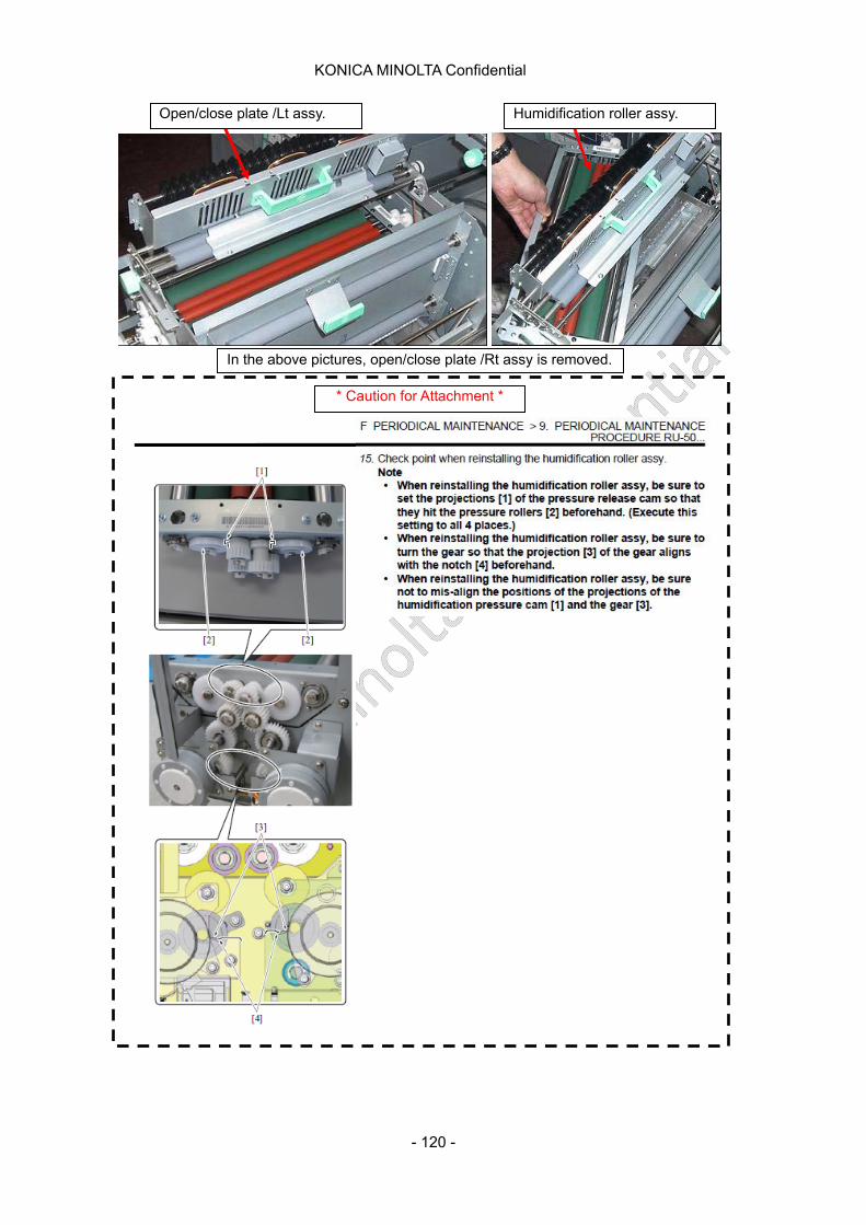
KONICA MINOLTA Confidential
In the above pictures, open/close plate /Rt assy is removed.
Open/close plate /Lt assy. Humidification roller assy.
* Caution for Attachment *
- 120 -
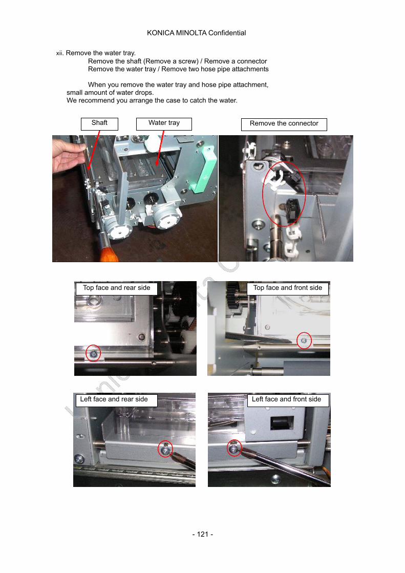
KONICA MINOLTA Confidential
xii. Remove the water tray. Remove the shaft (Remove a screw) / Remove a connector Remove the water tray / Remove two hose pipe attachments When you remove the water tray and hose pipe attachment,
small amount of water drops. We recommend you arrange the case to catch the water.
Shaft Water tray Remove the connector
Top face and rear side Top face and front side
Left face and front side Left face and rear side
- 121 -
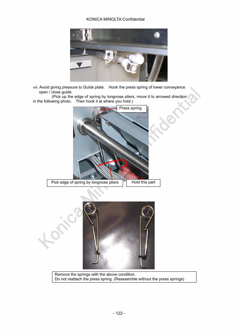
KONICA MINOLTA Confidential
xiii. Avoid giving pressure to Guide plate. Hook the press spring of lower conveyance open / close guide (Pick up the edge of spring by longnose pliers, move it to arrowed direction in the following photo. Then hook it at where you hold.)
Pick edge of spring by longnose pliers Hold this part
Remove the springs with the above condition. Do not reattach the press spring. (Reassemble without the press springs)
Press spring
- 122 -
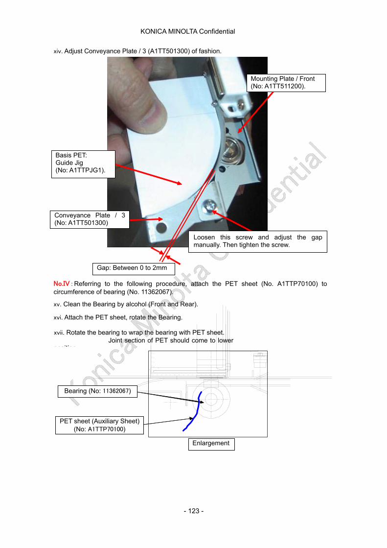
KONICA MINOLTA Confidential
Mounting Plate / Front (No: A1TT511200).
Basis PET: Guide Jig (No: A1TTPJG1).
Conveyance Plate / 3 (No: A1TT501300)
Gap: Between 0 to 2mm
Loosen this screw and adjust the gap manually. Then tighten the screw.
xiv. Adjust Conveyance Plate / 3 (A1TT501300) of fashion.
No.IV:Referring to the following procedure, attach the PET sheet (No. A1TTP70100) to circumference of bearing (No. 11362067).
xv. Clean the Bearing by alcohol (Front and Rear).
xvi. Attach the PET sheet, rotate the Bearing.
xvii. Rotate the bearing to wrap the bearing with PET sheet. Joint section of PET should come to lower position
Enlargement
PET sheet (Auxiliary Sheet) (No: A1TTP70100)
Bearing (No: 11362067)
- 123 -

KONICA MINOLTA Confidential
- 124 -
Bearing (Front and Rear)
Rear side
Front side
Enlargemen
Plastic block
Bearing (No: 11362067)
PET sheet Auxiliary Sheet) (No: A1TTP70100)
Joint line of PET sheet
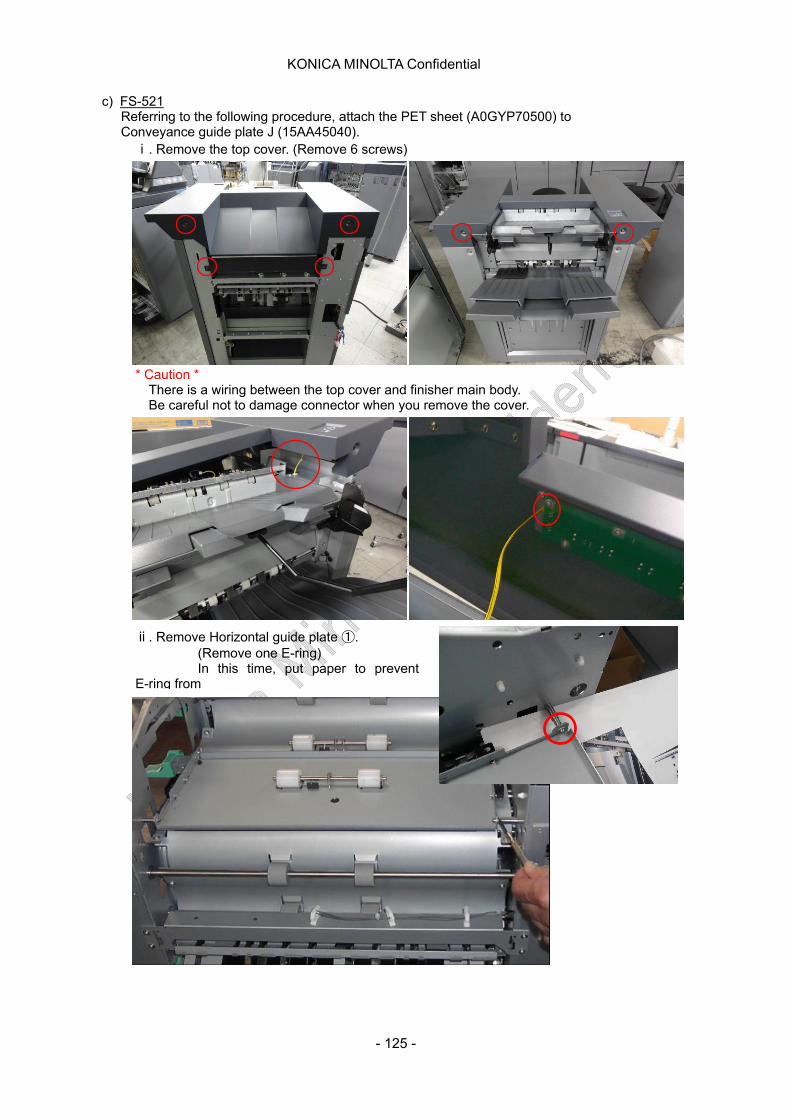
KONICA MINOLTA Confidential
c) FS-521 Referring to the following procedure, attach the PET sheet (A0GYP70500) to Conveyance guide plate J (15AA45040).
ⅰ. Remove the top cover. (Remove 6 screws)
* Caution * There is a wiring between the top cover and finisher main body. Be careful not to damage connector when you remove the cover.
1
ⅱ. Remove Horizontal guide plate ①. (Remove one E-ring) In this time, put paper to prevent E-ring from
- 125 -
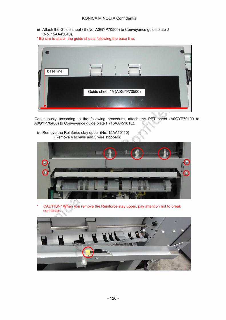
KONICA MINOLTA Confidential
ⅲ. Attach the Guide sheet / 5 (No. A0GYP70500) to Conveyance guide plate J (No. 15AA45040).
* Be sire to attach the guide sheets following the base line.
Continuously according to the following procedure, attach the PET sheet (A0GYP70100 to A0GYP70400) to Conveyance guide plate F (15AA45101E).
base line
Guide sheet / 5 (A0GYP70500)
ⅳ. Remove the Reinforce stay upper (No. 15AA10110) (Remove 4 screws and 3 wire stoppers)
* CAUTION* When you remove the Reinforce stay upper, pay attention not to break connector.
- 126 -

KONICA MINOLTA Confidential
ⅴ. Remove the Conveyance guide plate C (No. 15AA10110). (Remove 6 screws)
ⅵ. Remove the Conveyance guide plate E (No. 15AA45090). (Remove 2 screws)
ⅶ. Remove the E-ring and Bearing of two places Conveyance Roller. (Only front side)
- 127 -
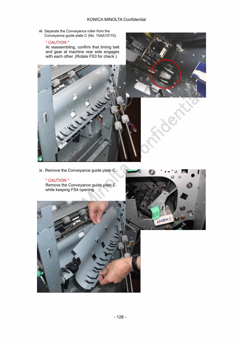
KONICA MINOLTA Confidential
ⅷ. Separate the Conveyance roller from the Conveyance guide plate C (No. 15AA10110).
* CAUTION * At reassembling, confirm that timing belt and gear at machine rear side engages with each other. (Rotate FS3 for check.)
* CAUTION * Remove the Conveyance guide plate C while keeping FS4 opening.
ⅸ. Remove the Conveyance guide plate C.
- 128 -

KONICA MINOLTA Confidential
ⅹ. Attach the Guide sheet / 1 to 4 to Conveyance guide plate C. * Be sure to attach the guide sheets, following the base line.
a) SD-506 Referring to the following procedure, attach the guide sheet (A0H2P701 / A0H2P702) to Entrance guide plate D (15AN45670).
ⅰ. Remove the left cover when you see from back side. (Remove 6 screws and loosen 2 screws)
Guide sheet / 1 (A0GYP70100)
Guide sheet / 4 (A0GYP70400)
Guide sheet / 3 (A0GYP70300)
Guide sheet / 2 (A0GYP70200)
Base line
- 129 -
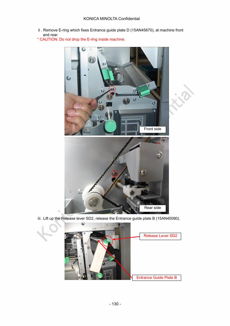
KONICA MINOLTA Confidential
ⅱ. Remove E-ring which fixes Entrance guide plate D (15AN45670), at machine front and rear. * CAUTION: Do not drop the E-ring inside machine.
Front side
Rear side
ⅲ. Lift up the Release lever SD2, release the Entrance guide plate B (15AN45090).
Entrance Guide Plate B
Release Lever SD2
- 130 -
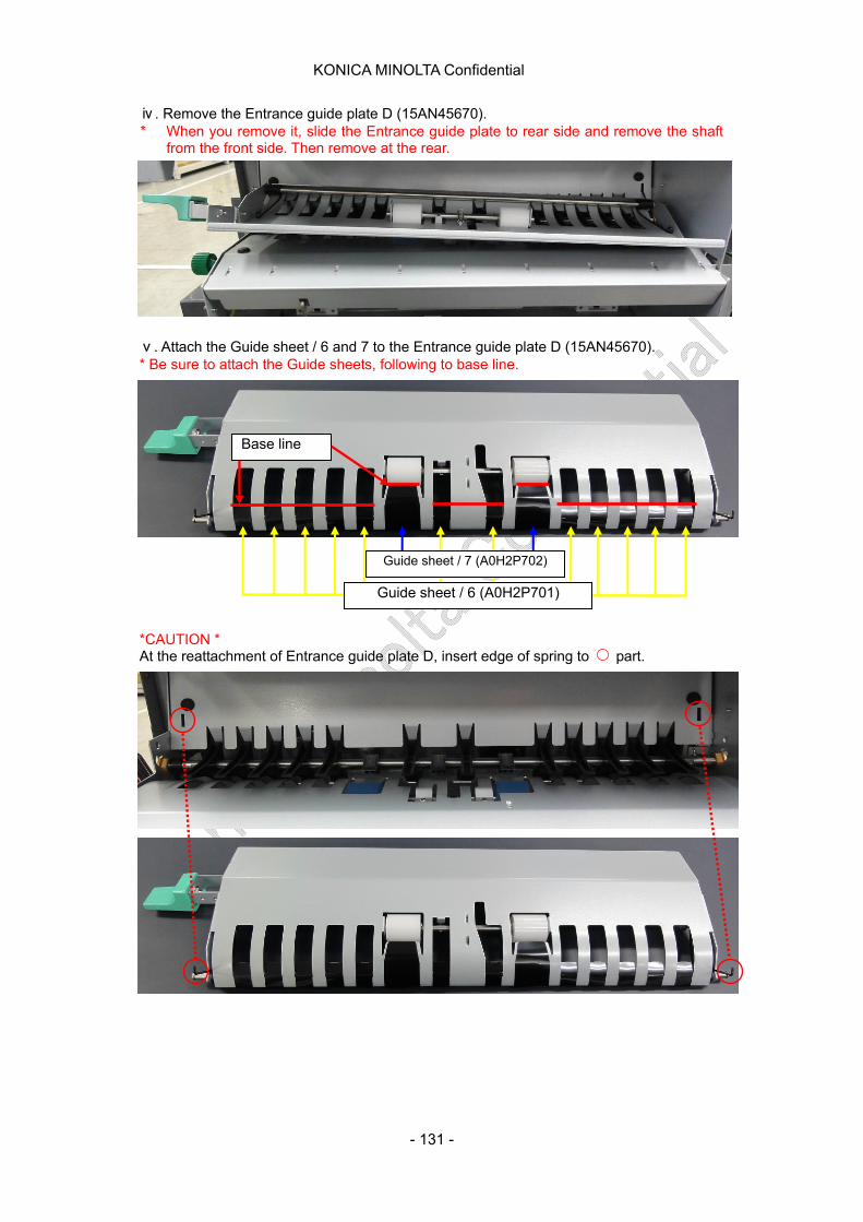
KONICA MINOLTA Confidential
ⅳ. Remove the Entrance guide plate D (15AN45670). * When you remove it, slide the Entrance guide plate to rear side and remove the shaft
from the front side. Then remove at the rear.
*CAUTION * At the reattachment of Entrance guide plate D, insert edge of spring to part.
Base line
Guide sheet / 7 (A0H2P702)
Guide sheet / 6 (A0H2P701)
ⅴ. Attach the Guide sheet / 6 and 7 to the Entrance guide plate D (15AN45670). * Be sure to attach the Guide sheets, following to base line.
- 131 -
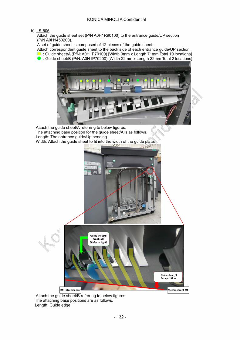
KONICA MINOLTA Confidential
b) LS-505 Attach the guide sheet set (P/N A0H1R90100) to the entrance guide/UP section (P/N A0H1450200). A set of guide sheet is composed of 12 pieces of the guide sheet. Attach correspondent guide sheet to the back side of each entrance guide/UP section.
: Guide sheet/A (P/N: A0H1P70100) [Width 9mm x Length 71mm Total 10 locations] : Guide sheet/B (P/N: A0H1P70200) [Width 22mm x Length 22mm Total 2 locations]
Attach the guide sheet/A referring to below figures. The attaching base position for the guide sheet/A is as follows. Length: The entrance guide/Up bending Width: Attach the guide sheet to fit into the width of the guide plate.
Attach the guide sheet/B referring to below figures. The attaching base positions are as follows. Length: Guide edge
- 132 -
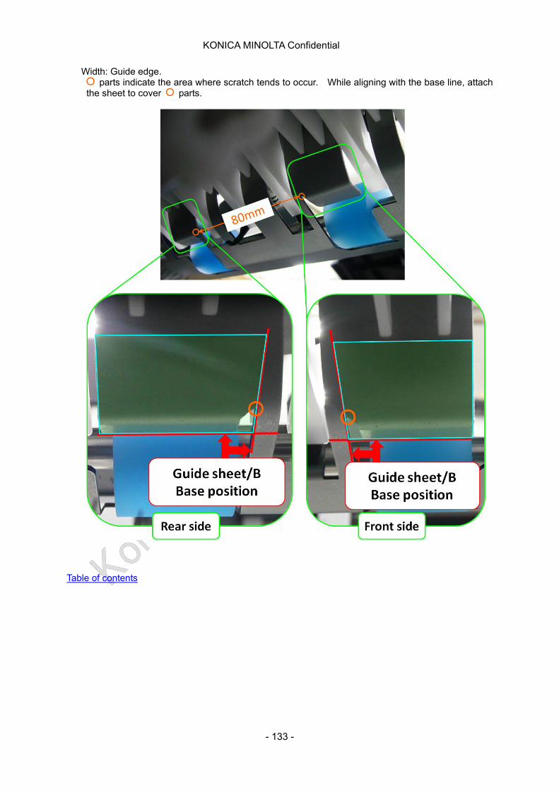
KONICA MINOLTA Confidential
Width: Guide edge. parts indicate the area where scratch tends to occur. While aligning with the base line, attach
the sheet to cover parts.
Table of contents
- 133 -
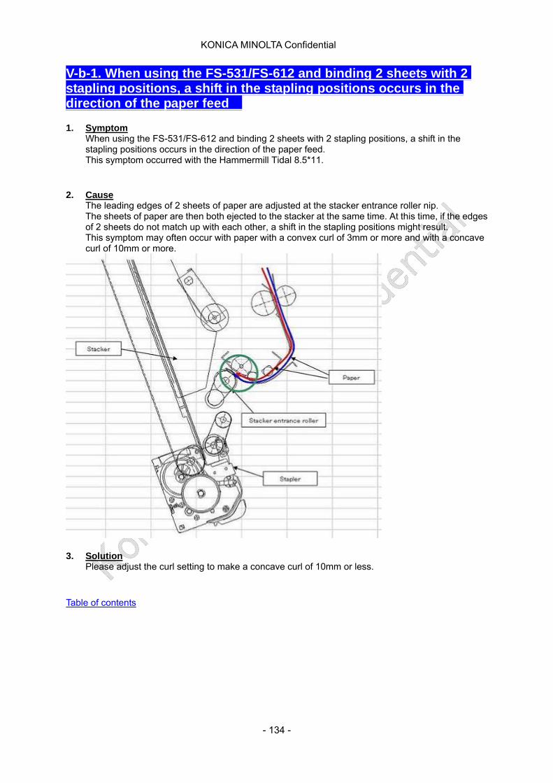
KONICA MINOLTA Confidential
V-b-1. When using the FS-531/FS-612 and binding 2 sheets with 2 stapling positions, a shift in the stapling positions occurs in the direction of the paper feed
1. Symptom
When using the FS-531/FS-612 and binding 2 sheets with 2 stapling positions, a shift in the stapling positions occurs in the direction of the paper feed. This symptom occurred with the Hammermill Tidal 8.5*11.
2. Cause
The leading edges of 2 sheets of paper are adjusted at the stacker entrance roller nip. The sheets of paper are then both ejected to the stacker at the same time. At this time, if the edges of 2 sheets do not match up with each other, a shift in the stapling positions might result. This symptom may often occur with paper with a convex curl of 3mm or more and with a concave curl of 10mm or more.
3. Solution
Please adjust the curl setting to make a concave curl of 10mm or less.
Table of contents
- 134 -
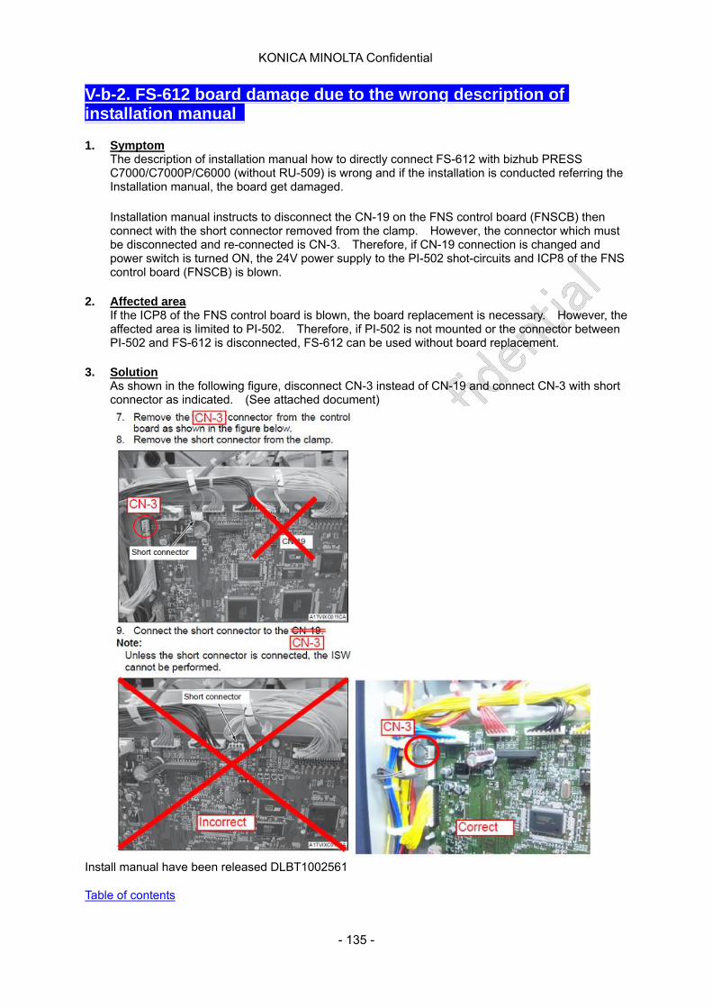
KONICA MINOLTA Confidential
V-b-2. FS-612 board damage due to the wrong description of installation manual 1. Symptom
The description of installation manual how to directly connect FS-612 with bizhub PRESS C7000/C7000P/C6000 (without RU-509) is wrong and if the installation is conducted referring the Installation manual, the board get damaged.
Installation manual instructs to disconnect the CN-19 on the FNS control board (FNSCB) then connect with the short connector removed from the clamp. However, the connector which must be disconnected and re-connected is CN-3. Therefore, if CN-19 connection is changed and power switch is turned ON, the 24V power supply to the PI-502 shot-circuits and ICP8 of the FNS control board (FNSCB) is blown.
2. Affected area
If the ICP8 of the FNS control board is blown, the board replacement is necessary. However, the affected area is limited to PI-502. Therefore, if PI-502 is not mounted or the connector between PI-502 and FS-612 is disconnected, FS-612 can be used without board replacement.
3. Solution
As shown in the following figure, disconnect CN-3 instead of CN-19 and connect CN-3 with short connector as indicated. (See attached document)
Install manual have been released DLBT1002561 Table of contents
- 135 -
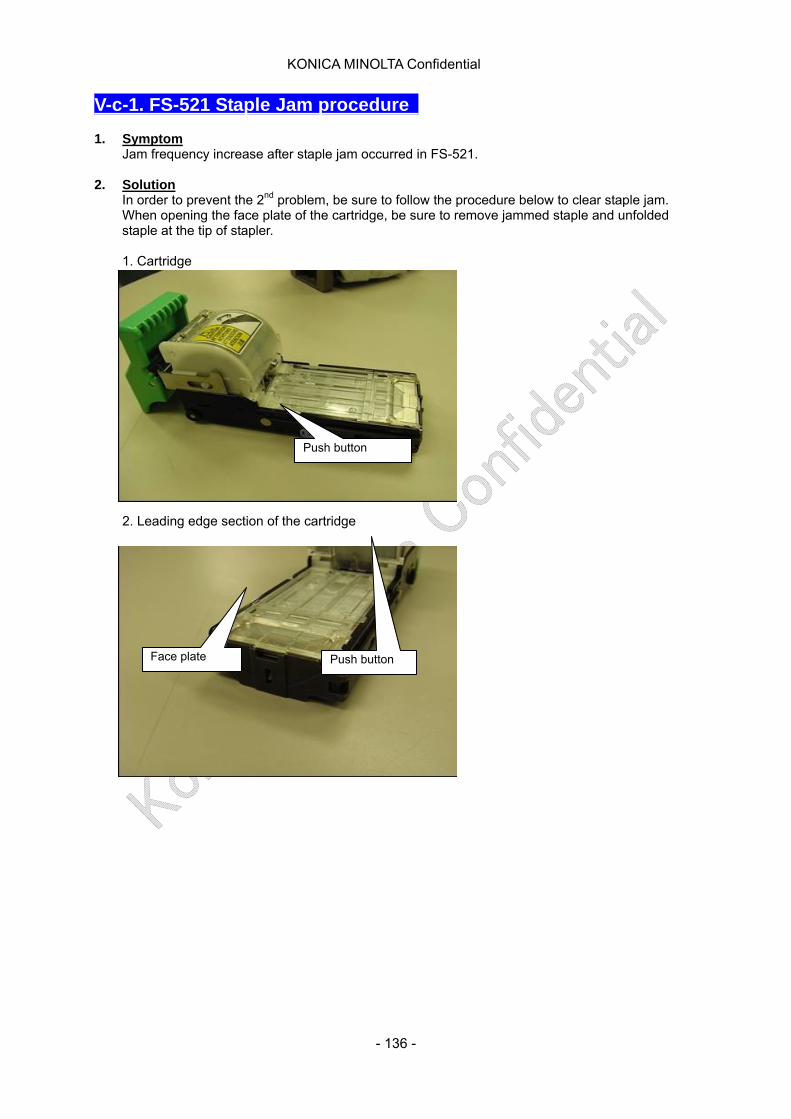
KONICA MINOLTA Confidential
V-c-1. FS-521 Staple Jam procedure 1. Symptom
Jam frequency increase after staple jam occurred in FS-521. 2. Solution
In order to prevent the 2nd problem, be sure to follow the procedure below to clear staple jam. When opening the face plate of the cartridge, be sure to remove jammed staple and unfolded staple at the tip of stapler.
1. Cartridge
Push button
2. Leading edge section of the cartridge
Face plate Push button
- 136 -

KONICA MINOLTA Confidential
3. When pressing the push button on both side of the cartridge, the face plate is unlocked and opens.
4. The condition of the face plate opened.
2
1
2
1
5. Remove the jam staple. Remove the jammed (malformed staple) and being folded staples.
Malformed staple and shaped staple (being folded staple)
- 137 -
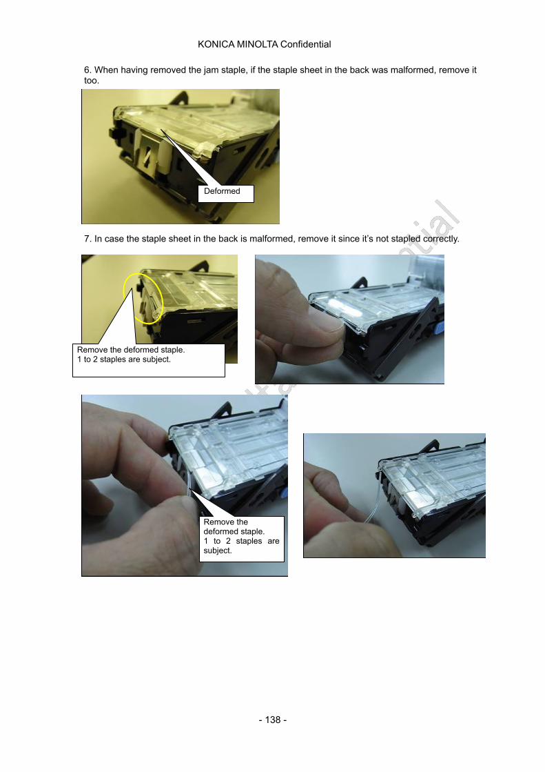
KONICA MINOLTA Confidential
6. When having removed the jam staple, if the staple sheet in the back was malformed, remove it too.
Deformed
7. In case the staple sheet in the back is malformed, remove it since it’s not stapled correctly.
Remove the deformed staple. 1 to 2 staples are subject.
Remove the deformed staple. 1 to 2 staples are subject.
- 138 -
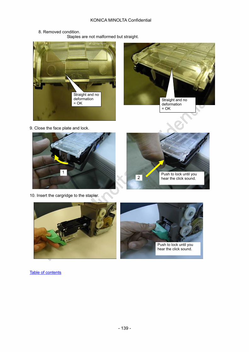
KONICA MINOLTA Confidential
8. Removed condition. Staples are not malformed but straight.
Straight and no deformation = OK
Straight and no deformation = OK
9. Close the face plate and lock.
1 Push to lock until you hear the click sound. 2
10. Insert the cargridge to the stapler.
Push to lock until you hear the click sound.
Table of contents
- 139 -
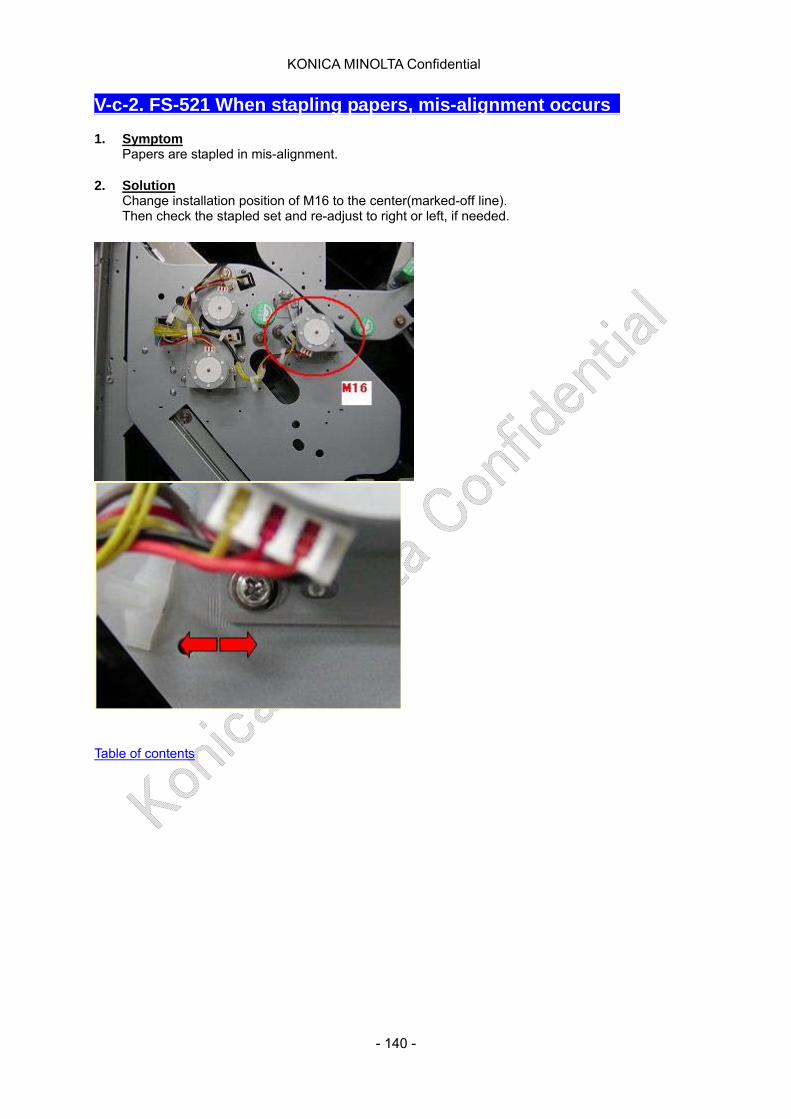
KONICA MINOLTA Confidential
V-c-2. FS-521 When stapling papers, mis-alignment occurs 1. Symptom
Papers are stapled in mis-alignment. 2. Solution
Change installation position of M16 to the center(marked-off line). Then check the stapled set and re-adjust to right or left, if needed.
Table of contents
- 140 -
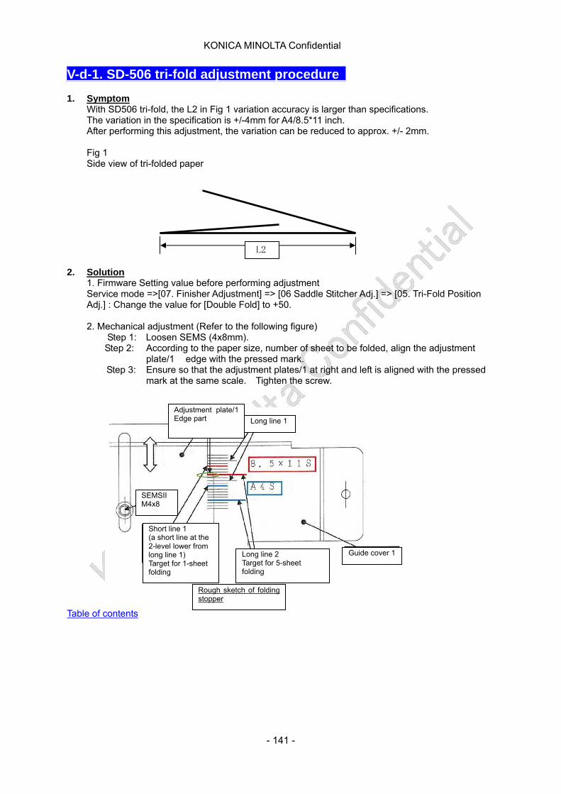
KONICA MINOLTA Confidential
V-d-1. SD-506 tri-fold adjustment procedure 1. Symptom
With SD506 tri-fold, the L2 in Fig 1 variation accuracy is larger than specifications. The variation in the specification is +/-4mm for A4/8.5*11 inch. After performing this adjustment, the variation can be reduced to approx. +/- 2mm.
Fig 1 Side view of tri-folded paper
L2
2. Solution
1. Firmware Setting value before performing adjustment Service mode =>[07. Finisher Adjustment] => [06 Saddle Stitcher Adj.] => [05. Tri-Fold Position Adj.] : Change the value for [Double Fold] to +50.
2. Mechanical adjustment (Refer to the following figure)
Step 1: Loosen SEMS (4x8mm). Step 2: According to the paper size, number of sheet to be folded, align the adjustment
plate/1 edge with the pressed mark. Step 3: Ensure so that the adjustment plates/1 at right and left is aligned with the pressed
mark at the same scale. Tighten the screw.
Long line 1
Adjustment plate/1 Edge part
SEMSII M4x8
Long line 2 Target for 5-sheet folding
Guide cover 1
Short line 1 (a short line at the 2-level lower from long line 1) Target for 1-sheet folding
Rough sketch of folding stopper
Table of contents
- 141 -
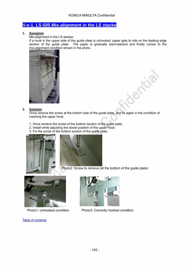
KONICA MINOLTA Confidential
V-e-1. LS-505 Mis-alignment in the LS stacke 1. Symptom
Mis-alignment in the LS stacker If a hook in the upper side of the guide plate is unhooked, paper gets to ride on the leading edge section of the guide plate. The paper is gradually slant-stacked and finally comes to the mis-alignment condition shown in the photo.
2. Solution
Once remove the screw at the bottom side of the guide plate, and fix again in the condition of inserting the upper hook.
1. Once remeve the screw of the bottom section of the guide plate. 2. Install while adjusting the dowel position of the upper hook. 3. Fix the screw of the bottom section of the guide plate.
Photo2: Screw to remove (at the bottom of the guide plate)
Photo1: Unhooked condition Photo3: Correctly hooked condition
Table of contents
- 142 -

KONICA MINOLTA Confidential
V-e-2. LS-505 The door opens with its rebound 1. Symptom
When shut the LS front door, the door opens with its rebound. It is prefered to strengthen the LS front door lock. Caution: Front door’s magnet catch holding power is optimized at present considering the pressure on the door when it opens.
2. Solution
Modification 1. Magnet catch’s contact mark being centered, draw the frame (approx. 20mm) by pencil and mask its outside. (It may be good to use the masking tape or packaging tape.)
2. Using rough sand paper (#800), first rub the painted surface roughly and then polish the iron surface with finer sand paper (#800) carefully. 3. Apply lacquer.
-Be noted when the lacquer painting gets thicker, the magnetic force gets weaker. -When lacquer is not available, use grease temporally to prevent rusting. Then, apply lacquer later. (When painting lacquer, remove the grease completely)
4. Remove the masking tape and the modification is completed.
Table of contents
- 143 -
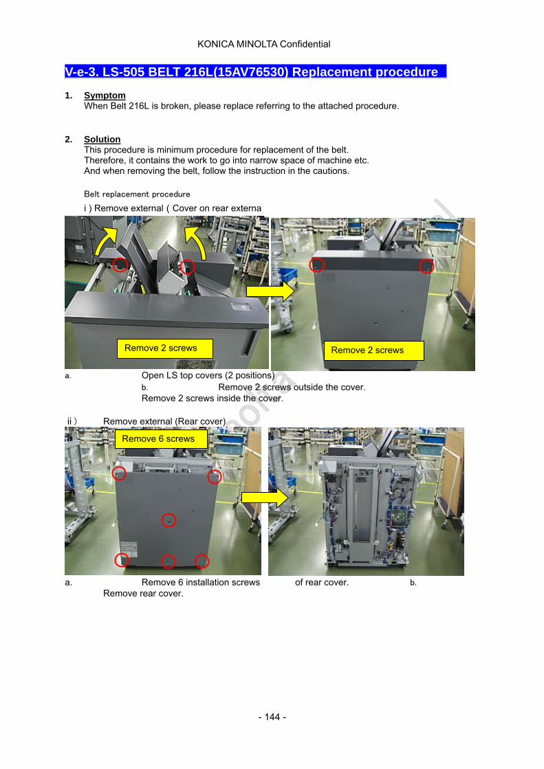
KONICA MINOLTA Confidential
V-e-3. LS-505 BELT 216L(15AV76530) Replacement procedure 1. Symptom
When Belt 216L is broken, please replace referring to the attached procedure.
2. Solution
This procedure is minimum procedure for replacement of the belt. Therefore, it contains the work to go into narrow space of machine etc. And when removing the belt, follow the instruction in the cautions.
Belt replacement procedure
i ) Remove external(Cover on rear externa
a. Open LS top covers (2 positions) b. Remove 2 screws outside the cover.
Remove 2 screws Remove 2 screws
Remove 2 screws inside the cover.
ⅱ) Remove external (Rear cover)
a. Remove 6 installation screws of rear cover. b. Remove rear cover.
Remove 6 screws
- 144 -

KONICA MINOLTA Confidential
ⅲ) Remove external (Cover on front external)
a.Remove 3 installation screws inside cover. b.Remove 2 screws at right top and left top.
c.Disconnect connectors. d.Remove a top front cover.
ⅳ) Remove external(Front inner Cove)
Remove 3 screws Remove 2 screws
Disconnect the connector
Remove 4 screws
a.Loosen screw of JAM release knob and remove. b.Remove 4 cover installation screws. the knob (JAM release knobs are at 3 positions)
- 145 -

KONICA MINOLTA Confidential
c.Disconnect connectors. d.Remove inner cover at front.
ⅴ) Remove tension brack (Front side)
a.Remove 2 screws for tension bracket (front) b.Remove tension spring from bracket.
c.Remove tension bracket and bearings.
Remove the connector
Remove 2 screws Remove the tension
Remove the tension braket and the bearin
- 146 -
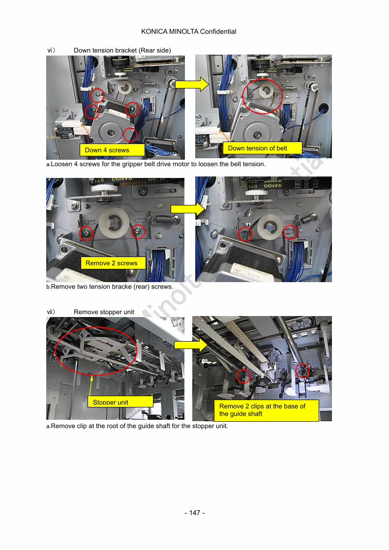
KONICA MINOLTA Confidential
ⅵ) Down tension bracket (Rear side)
a.Loosen 4 screws for the gripper belt drive motor to loosen the belt tension.
b.Remove two tension bracke (rear) screws.
Remove 2 screws
Down 4 screws Down tension of belt
ⅶ) Remove stopper unit
a.Remove clip at the root of the guide shaft for the stopper unit.
Stopper unit Remove 2 clips at the base of the guide shaft
す
- 147 -
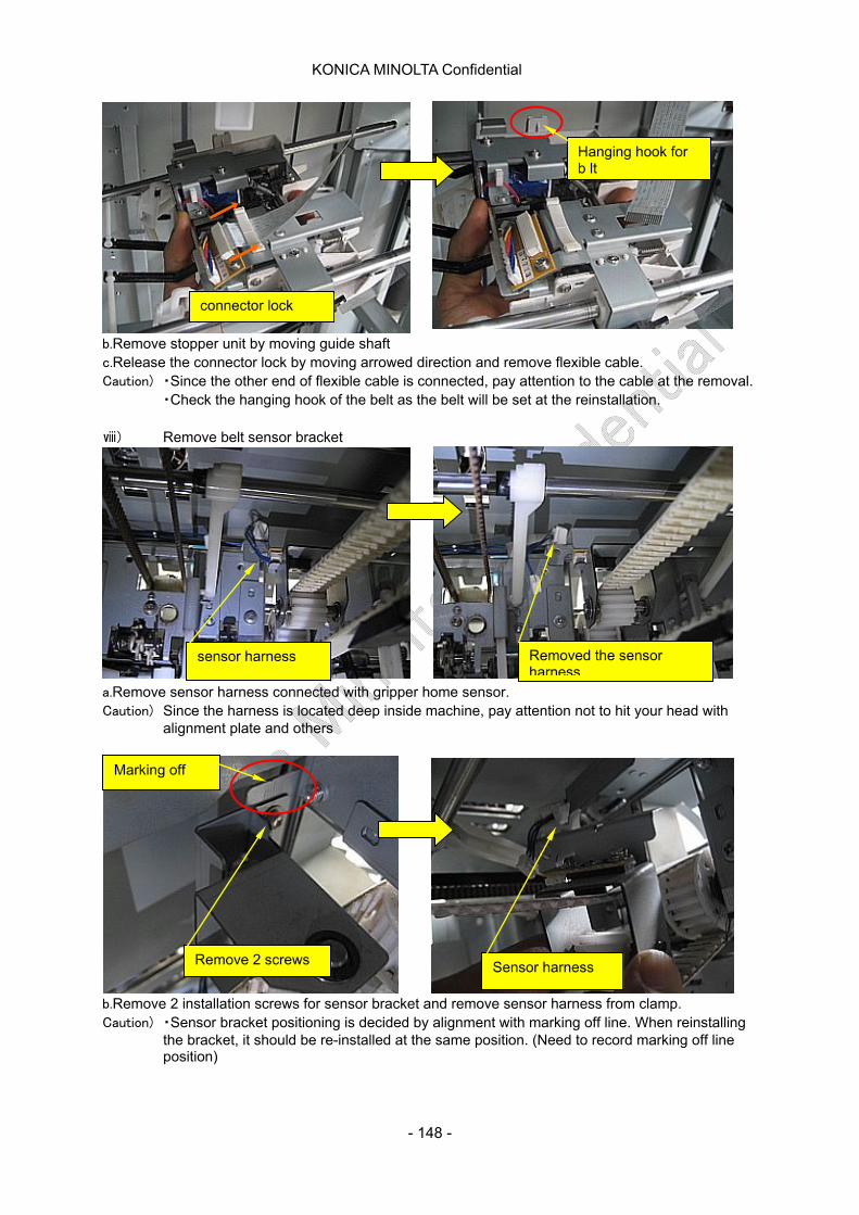
KONICA MINOLTA Confidential
b.Remove stopper unit by moving guide shaft c.Release the connector lock by moving arrowed direction and remove flexible cable. Caution) ・Since the other end of flexible cable is connected, pay attention to the cable at the removal. ・Check the hanging hook of the belt as the belt will be set at the reinstallation.
ⅷ) Remove belt sensor bracket
a.Remove sensor harness connected with gripper home sensor. Caution) Since the harness is located deep inside machine, pay attention not to hit your head with
alignment plate and others
b.Remove 2 installation screws for sensor bracket and remove sensor harness from clamp.
connector lock
Hanging hook for b lt
sensor harness Removed the sensor harness
Remove 2 screws Sensor harness
Marking off
Caution) ・Sensor bracket positioning is decided by alignment with marking off line. When reinstalling the bracket, it should be re-installed at the same position. (Need to record marking off line position)
- 148 -
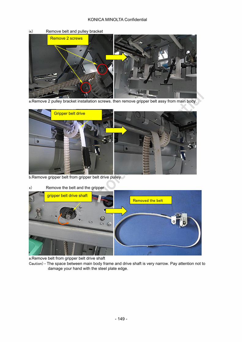
KONICA MINOLTA Confidential
ix) Remove belt and pulley bracket
Remove 2 screws
a.Remove 2 pulley bracket installation screws. then remove gripper belt assy from main body.
Gripper belt drive
b.Remove gripper belt from gripper belt drive pulley
x) Remove the belt and the gripper
Removed the belt gripper belt drive shaft
a.Remove belt from gripper belt drive shaft Caution) - The space between main body frame and drive shaft is very narrow. Pay attention not to
damage your hand with the steel plate edge.
- 149 -
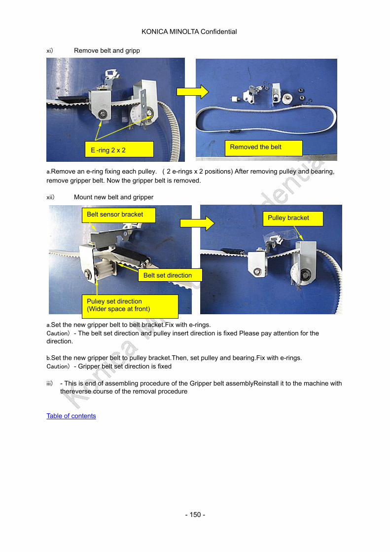
KONICA MINOLTA Confidential
xi) Remove belt and gripp
E-ring 2 x 2 Removed the belt
a.Remove an e-ring fixing each pulley. (2 e-rings x 2 positions) After removing pulley and bearing, remove gripper belt. Now the gripper belt is removed.
xii) Mount new belt and gripper
Pulley bracket
Belt set direction
Pulley set direction (Wider space at front)
Belt sensor bracket
a.Set the new gripper belt to belt bracket.Fix with e-rings. Caution) - The belt set direction and pulley insert direction is fixed Please pay attention for the direction.
b.Set the new gripper belt to pulley bracket.Then, set pulley and bearing.Fix with e-rings. Caution) - Gripper belt set direction is fixed
iii) - This is end of assembling procedure of the Gripper belt assemblyReinstall it to the machine with thereverse course of the removal procedure
Table of contents
- 150 -
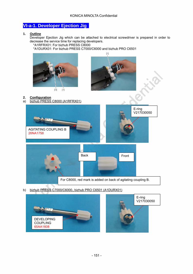
KONICA MINOLTA Confidential
VI-a-1. Developer Ejection Jig 1. Outline
Developer Ejection Jig which can be attached to electrical screwdriver is prepared in order to decrease the service time for replacing developers.
*A1RFRX01: For bizhub PRESS C8000 *A1DURX01: For bizhub PRESS C7000/C6000 and bizhub PRO C6501
2. Configuration a) bizhub PRESS C8000 (A1RFRX01)
E-ring V217030050
AGITATING COUPLING B 26NA1758
Back Front
For C8000, red mark is added on back of agitating coupling B.
b) bizhub PRESS C7000/C6000、bizhub PRO C6501 (A1DURX01)
E-ring V217030050
DEVELOPING COUPLING 65AA1608
- 151 -
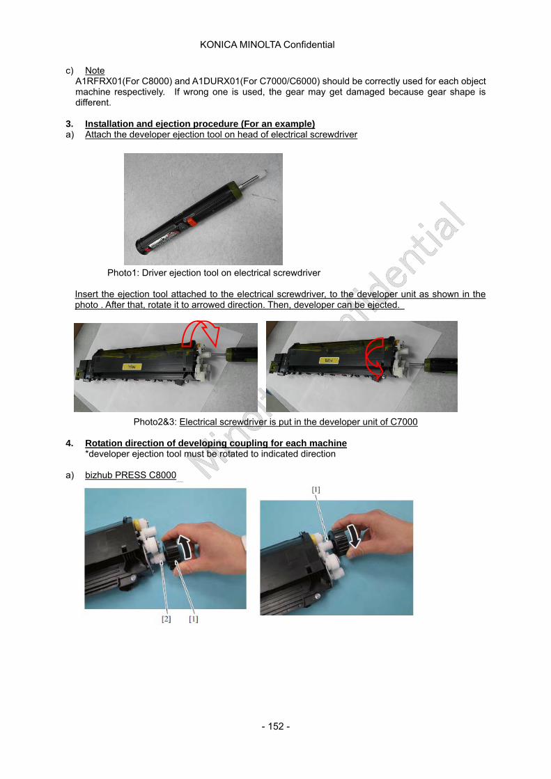
KONICA MINOLTA Confidential
c) Note A1RFRX01(For C8000) and A1DURX01(For C7000/C6000) should be correctly used for each object machine respectively. If wrong one is used, the gear may get damaged because gear shape is different.
3. Installation and ejection procedure (For an example) a) Attach the developer ejection tool on head of electrical screwdriver Photo1: Driver ejection tool on electrical screwdriver
Insert the ejection tool attached to the electrical screwdriver, to the developer unit as shown in the photo . After that, rotate it to arrowed direction. Then, developer can be ejected.
Photo2&3: Electrical screwdriver is put in the developer unit of C7000 4. Rotation direction of developing coupling for each machine
*developer ejection tool must be rotated to indicated direction
a) bizhub PRESS C8000
- 152 -
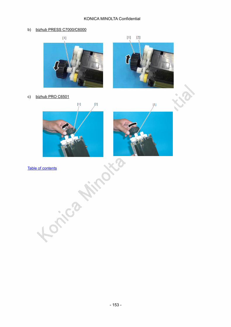
KONICA MINOLTA Confidential
- 153 -
b) bizhub PRESS C7000/C6000 c) bizhub PRO C6501 Table of contents