Troubleshooting electrical problems in high-end...
3
Application Note Troubleshooting electrical problems in high-end TVs Using logging and TrendCapture in the Fluke 289 DMM From the Fluke Digital Library @ www.fluke.com/library These troubleshooting steps feature the Fluke 289 DMM because of its onscreen trending capabilities. TrendCapture helps troubleshooters spot anomalies faster by showing results on-screen as soon as recording sessions are complete. Follow correct safety procedures for testing live circuits. Use a safety- rated, fused digital multimeter (DMM) and test a known voltage source first to make sure your meter is operating properly. 1. Testing over voltage or supply overload shut- down in televisions: Most televisions sets that use CRT’s have shut- down circuits that turn off the TV when the high voltage goes too high. These same sets also have circuits that detect excessive supply voltage or load currents for several low voltage supplies. It is often a real challenge to find an intermittent shutdown problem because most TV’s do not have built in circuits that indicate which supply is intermittently overloaded or has intermittent excessive voltage. You can use the Fluke 289 Digital Multimeter (DMM) to find the power supply that is caus- ing the shutdown problem. Connect the meter across the HV/deflection supply, monitor the voltage level, and record the voltage level over a period of time. You can also set the meter in MIN-MAX mode, wait for the shutdown to occur, and observe the maximum voltage. If you don’t see an over voltage problem, test another supply. For some supplies, you may be able to access the current sense shunt, and then you can easily connect the meter across the resistor to monitor the current in MIN-MAX mode. 2. Testing for cause of repeated failure of con- vergence amplifiers in projection televisions. Projection television sets that use three projec- tion CRT’s have circuits that dynamically modify the deflection of the electron beams in the three tubes to converge the three colors displayed on the screen. The convergence is done by driving secondary deflection yokes with hybrid power amplifiers. These amplifiers are usually pack- aged two or three in a hybrid assembly. The amplifiers are fairly reliable, but occasion- ally there may be a set where the amplifiers fail in less than a year, and the replacement amplifier fails in six to nine months. Using a 289 DMM and a temperature probe, you can conduct a simple extra check to determine if a repair is really complete and the TV will not have a repeating failure. After a hybrid amplifier assembly has been replaced, connect the temperature probe to the amplifier assembly and heat sink (at the junc- tion of the body of the amplifier assembly and
Transcript of Troubleshooting electrical problems in high-end...
Application Note
Troubleshooting electrical problems in high-end TVs
Using logging and TrendCapture in the Fluke 289 DMM
F r o m t h e F l u k e D i g i t a l L i b r a r y @ w w w. f l u k e . c o m / l i b r a r y
These troubleshooting steps feature the Fluke 289 DMM because of its onscreen trending capabilities. TrendCapture helps troubleshooters spot anomalies faster by showing results on-screen as soon as recording sessions are complete. Follow correct safety procedures for testing live circuits. Use a safety-rated, fused digital multimeter (DMM) and test a known voltage source first to make sure your meter is operating properly.
1. Testing over voltage or supply overload shut-down in televisions:
Most televisions sets that use CRT’s have shut-down circuits that turn off the TV when the high voltage goes too high. These same sets also have circuits that detect excessive supply voltage or load currents for several low voltage supplies. It is often a real challenge to find an intermittent shutdown problem because most TV’s do not have built in circuits that indicate which supply is intermittently overloaded or has intermittent excessive voltage.
You can use the Fluke 289 Digital Multimeter (DMM) to find the power supply that is caus-ing the shutdown problem. Connect the meter across the HV/deflection supply, monitor the voltage level, and record the voltage level over a period of time. You can also set the meter in MIN-MAX mode, wait for the shutdown to occur, and observe the maximum voltage. If you don’t see an over voltage problem, test another supply. For some supplies, you may be able to access the current sense shunt, and then you can easily connect the meter across the resistor to monitor the current in MIN-MAX mode.
2. Testing for cause of repeated failure of con-vergence amplifiers in projection televisions.
Projection television sets that use three projec-tion CRT’s have circuits that dynamically modify the deflection of the electron beams in the three tubes to converge the three colors displayed on the screen. The convergence is done by driving secondary deflection yokes with hybrid power amplifiers. These amplifiers are usually pack-aged two or three in a hybrid assembly.
The amplifiers are fairly reliable, but occasion-ally there may be a set where the amplifiers fail in less than a year, and the replacement amplifier fails in six to nine months. Using a 289 DMM and a temperature probe, you can conduct a simple extra check to determine if a repair is really complete and the TV will not have a repeating failure.
After a hybrid amplifier assembly has been replaced, connect the temperature probe to the amplifier assembly and heat sink (at the junc-tion of the body of the amplifier assembly and

2 Fluke Corporation Troubleshooting electrical problems in high-end TVs
the heat sink). Set up the 289 DMM to record the temperature at ten second intervals and start recording. Turn on the TV and allow the set to warm up to its normal operating temperature, about 20 to 30 minutes. After about 15 minutes, the temperature should be around 45 °C to 55 °C. Figure 1 shows the screen shots of the temperature recordings for a normal amplifier and an amplifier that is running too hot.
3. Troubleshooting intermittent turn-on problem in projection television.
An older projection TV had a problem where it intermittently would turn on and have sound, but no picture. If you turned off the set, waited about two minutes, then turned the set back on, you could get a picture about one time in three tries. The problem was that one of the switching power supplies did not start up every time the set was turned on.
Using the 289 DMM, the problem was traced to the startup circuit where there was a defective electrolytic capacitor. The DMM was connected across the supply for the controller IC. When the controller IC was enabled, the supply would drop below the minimum supply voltage needed for the controller to operate. Figure 2 is a screen shot of the supply voltage for the controller IC with the TV turned on. The screen shot is a recording made after the capacitor was replaced. Before the capacitor was replaced, the volt-age dropped below 12 V, below the low supply threshold, shutting the IC down. The Zoom fea-ture enables the technician to examine the volt-age levels as the supply is being enabled and turned on.
4. Verification of power supply input over voltage shutdown:
On some projection television sets, the power supply is designed to shut down if the line volt-age in above a certain level. It is important to verify that the power supply does shutdown if the line voltage goes above this set level. Using the recording function, of the 289 DMM, the test can easily be done.
The TV connects to the power line through a Variac (variable auto-transformer). Set the 289 DMM up to record in ac volts at one second intervals. Turn the TV on with the line voltage set to approximately 120 V. Connect the 289 DMM across the line and start the recording. Slowly increase the line voltage until the TV turns itself off or shuts down. Do not exceed 140 V if the TV does not shut down; there is something wrong with the shutdown circuit in the TV.
Figure 1. Left Screen Shot shows an amplifier that is running too hot. Right Screen Shot shows an amplifier running at normal temperature.
Figure 2. Screen shot showing the controller IC supply voltage as the supply is being turned on. Before the supply is enabled, the voltage is about 24.75 V and drops to approximately 17 V.
3 Fluke Corporation Troubleshooting electrical problems in high-end TVs
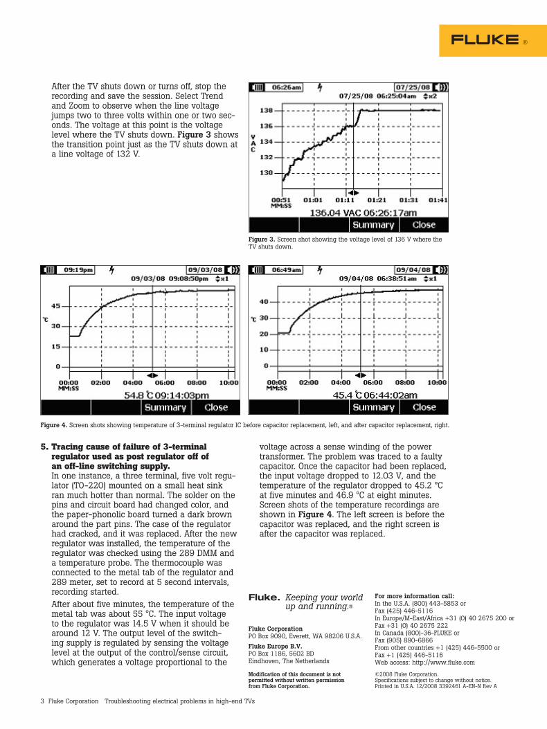
After the TV shuts down or turns off, stop the recording and save the session. Select Trend and Zoom to observe when the line voltage jumps two to three volts within one or two sec-onds. The voltage at this point is the voltage level where the TV shuts down. Figure 3 shows the transition point just as the TV shuts down at a line voltage of 132 V.
5. Tracing cause of failure of 3-terminal regulator used as post regulator off of an off-line switching supply.
In one instance, a three terminal, five volt regu-lator (TO-220) mounted on a small heat sink ran much hotter than normal. The solder on the pins and circuit board had changed color, and the paper-phonolic board turned a dark brown around the part pins. The case of the regulator had cracked, and it was replaced. After the new regulator was installed, the temperature of the regulator was checked using the 289 DMM and a temperature probe. The thermocouple was connected to the metal tab of the regulator and 289 meter, set to record at 5 second intervals, recording started.
After about five minutes, the temperature of the metal tab was about 55 °C. The input voltage to the regulator was 14.5 V when it should be around 12 V. The output level of the switch-ing supply is regulated by sensing the voltage level at the output of the control/sense circuit, which generates a voltage proportional to the
Figure 4. Screen shots showing temperature of 3-terminal regulator IC before capacitor replacement, left, and after capacitor replacement, right.
Figure 3. Screen shot showing the voltage level of 136 V where the TV shuts down.
voltage across a sense winding of the power transformer. The problem was traced to a faulty capacitor. Once the capacitor had been replaced, the input voltage dropped to 12.03 V, and the temperature of the regulator dropped to 45.2 °C at five minutes and 46.9 °C at eight minutes. Screen shots of the temperature recordings are shown in Figure 4. The left screen is before the capacitor was replaced, and the right screen is after the capacitor was replaced.
Fluke Corporation PO Box 9090, Everett, WA 98206 U.S.A.
Fluke Europe B.V. PO Box 1186, 5602 BD Eindhoven, The Netherlands
Fluke. Keeping your world up and running.®
For more information call: In the U.S.A. (800) 443-5853 or Fax (425) 446-5116 In Europe/M-East/Africa +31 (0) 40 2675 200 or Fax +31 (0) 40 2675 222 In Canada (800)-36-FLUKE or Fax (905) 890-6866 From other countries +1 (425) 446-5500 or Fax +1 (425) 446-5116 Web access: http://www.fluke.com
©2008 Fluke Corporation. Specifications subject to change without notice. Printed in U.S.A. 12/2008 3392461 A-EN-N Rev A
Modification of this document is not permitted without written permission from Fluke Corporation.