Trouble Shooting Guide, Standard - Телефоны, обзоры,...
26
Trouble Shooting Guide, Standard 4/00021-2/FEA 209 544/21 B Approved according to 1776-2/FEA 209 544 Trouble Shooting Guide, Standard Applicable for R320s and R320sc Contents 1 Explanations .................................................................................................................... 2 2 Network Problems........................................................................................................... 5 3 On/Off Problems ............................................................................................................. 9 4 Audio Problems ............................................................................................................. 12 5 Display/Illumination Problems .................................................................................... 15 6 Capacity/Charging Problems ....................................................................................... 17 7 SIM Problems ................................................................................................................ 18 8 Key Problems................................................................................................................. 19 9 Alert Problems............................................................................................................... 20 10 Data Communication Problems ................................................................................... 23 11 Other Problems ............................................................................................................. 24 12 Software Problems ........................................................................................................ 25 13 Revision History ............................................................................................................ 26
Transcript of Trouble Shooting Guide, Standard - Телефоны, обзоры,...

Trouble Shooting Guide, Standard
4/00021-2/FEA 209 544/21 B Approved according to 1776-2/FEA 209 544
Trouble Shooting Guide, StandardApplicable for R320s and R320sc
Contents
1 Explanations ....................................................................................................................2
2 Network Problems...........................................................................................................5
3 On/Off Problems .............................................................................................................9
4 Audio Problems.............................................................................................................12
5 Display/Illumination Problems ....................................................................................15
6 Capacity/Charging Problems.......................................................................................17
7 SIM Problems................................................................................................................18
8 Key Problems.................................................................................................................19
9 Alert Problems...............................................................................................................20
10 Data Communication Problems...................................................................................23
11 Other Problems .............................................................................................................24
12 Software Problems ........................................................................................................25
13 Revision History ............................................................................................................26
Trouble Shooting Guide, Standard
4/00021-2/FEA 209 544/21 B 2(26)
1 Explanations
For component placing see document 1078-2/FEA 209 544/21
1.1 Pin Placing
Single diode (PIN diode). Electrolytic capacitor.
Double diode or singletransistor.
Five pin circuit (usuallyvoltage regulator).
Double transistor.
Eight pin circuit. Ten pin circuit. Sixteen pin circuit
Crystal N200 N234

Trouble Shooting Guide, Standard
4/00021-2/FEA 209 544/21 B 3(26)
1.2 Abbreviations
B: Crystal.
C: Capacitor.
D: Digital circuit.
F: Overvoltage protection.
H: Buzzer, LED, pads for display.
J: Connector.
L: Coil.
N: Analogue circuit.
R: Resistor.
S: Keyboard pads.
U: BALUN Component that converts a balanced signal to an unbalanced or the other wayaround.
V: Transistor, diode.
X: Contact surface on the circuit board.
Z: Filter.
DCIO: DC voltage through the system connector for charging.
GND: Ground.
EL_HIGH: Logical signal that activates the background illumination.
EL_LOW: Logical signal that activates the background illumination.
ONSWAn: Voltage from the On/Off key that starts the phone.
RTC: Real Time Clock. The clock that keeps track of time.
SIMCLK: Signal from the processor used for communication to SIM, clock signal.
SIMDAT: Signal from the processor used for communication to SIM, data signal.
SIMRST: Signal from the processor used for communication to SIM, reset signal.
SIMVCC: Feed voltage for SIM.
VBATT: Battery voltage.
VCORE: DC voltage for the processor and memory at, for instance, stand by mode.Lower than VDIG.
VDIG: DC voltage for the processor and memory.
VDSPC: DC voltage for the DSP (Digital Signal Processor).
VLCD: DC voltage for the display that controls the contrast.
VRAD: DC voltage for the radio part except the synthesizer.
V380B: DC voltage for the radio part.
VRTC: DC voltage for the real time clock.
VVCO: DC voltage for the synthesizer.

Trouble Shooting Guide, Standard
4/00021-2/FEA 209 544/21 B 4(26)
I2C: Communications standard for two-way communication using only 2 wires,clock and data.

Trouble Shooting Guide, Standard
4/00021-2/FEA 209 544/21 B 5(26)
2 Network Problems
2.1 Find out if the problem is Rx- or Tx-related
Connect the phone (with signalling program) to a GSM test instrument and try to get SERV atan input signal strength of -68.5dBm.
If the phone does not get SERV, go to section 2.2.If the phone gets SERV, go to section 2.3.
2.2 The phone does not get SERV
Open the phone and check for liquid damage.
Make sure that the antenna connector (W100,Fig. 2.1) is correctly soldered, and notmechanically damaged, dirty or oxidised. Clean, resolder or replace if needed.
Fig. 2.1
Check the soldering of N234, N200, Z200 and Z201.
Measure the resistance of R220, R221, R222 and R223, (all 0 ohm).Replace if incorrect.
Check C312 for bad soldering, resolder carefully if necessary.
Retry to get SERV again with the settings mentioned above.
If the phone gets SERV, go to section 2.3.If the phone still does not get SERV it is probably within the LO part that the fault lies or thelosses in the signal path are too large. It is also possible that the feed voltages are incorrect.
Open the phone.
Power up the board and start it by pressing the On/Off key.

Trouble Shooting Guide, Standard
4/00021-2/FEA 209 544/21 B 6(26)
Measure the VRAD voltage at C501, at the side close to N700 (3.80 V).If the voltage is incorrect, send the unit on according to the local company directives
Measure the V380B voltage at C500, at the side close to C421 (3.80 V).If the voltage is incorrect, send the unit on according to the local company directives
Measure the VVCO voltage at pin 5 of N502 (3.80 V).If the VVCO voltage is correct, go to section 2.2.1.
If the voltage is incorrect, measure the voltage at L500 (3.70 V), at the side close to C503.If the voltage at L500 is correct, measure the voltage at V500, at the side close to N700. Itshall be more than 4.10 V.If the voltage at V500 is correct, measure the voltage at pin 1 of N502, it shall be more than4.10 V.If the voltage at pin 1 of N502 is incorrect send the unit on according to the local companydirectives.
If the voltage at pin 1 of N502 is correct, measure the voltage at pin 3 of N502 (3.80 V).If the voltage at pin 3 of N502 is correct, replace N502.
If the voltage at pin 3 of N502 is incorrect send the unit on according to the local companydirectives
If the voltage at V500 (at the side close to L500) is 3.70 V, replace V500, otherwise send theunit on according to the local company directives.
If the voltage at L500, at the side close to C503, is incorrect, measure the resistance of L500(0 ohm).If the resistance is correct, send the unit on according to the local company directives
If the resistance is too high, replace L500.
2.2.1 Check the feed voltages
The VRAD voltage for N234:
Measure the voltage at pin 5 of N234 (3.80 V).If the voltage is incorrect, measure the resistance of L211 (0 ohm).If the resistance is incorrect, replace L211.
If the resistance is correct, measure the resistance from one the sides of L211 to ground (2Mohms).If the resistance from L211 to ground is incorrect, replace C214, C211 and C212.
Measure the voltage at pin 47 of N234 (3.80 V).If the voltage is incorrect, measure the resistance of R345 (18 ohms).If the resistance is incorrect, replace R345.
If the resistance is correct, measure the resistance from pin 47 of N234 to ground (2Mohms).If the resistance from pin 47 of N234 to ground is incorrect, replace C345 and R345.
Trouble Shooting Guide, Standard
4/00021-2/FEA 209 544/21 B 7(26)
Measure the voltage at pin 62 of N234 (3.80 V).If the voltage is incorrect, measure the resistance of L370 (0 ohm).If the resistance is incorrect, replace L370.
If the resistance is correct, measure the resistance from one of the sides of L370 to ground (>1Mohm).If the resistance from L370 to ground is incorrect, replace C373 and R362.
The VVCO voltage for D300:
Measure the voltage at R303 (3.80 V), at the side close to R346.If the voltage is incorrect, measure the resistance of R303 (18 ohms).If the resistance is incorrect, replace R303.
If the resistance is correct, measure the resistance at R303, (at the side close to R346), toground (130 kohms).If the resistance at R303 is incorrect, replace C303.
Measure the voltage at the marked side of R334 (3.80 V).If the voltage is incorrect, measure the resistance of R334 (10 ohms).If the resistance is incorrect, replace R334.
If the fault remains, send the unit on according to the local company directives.
2.3 Connect a call at –68.5dBm input signal andpowerlevel 5
If you are able to connect a call, continue at 2.4.If you are not able to connect a call, open the phone and check for liquid damage.
Make sure that the antenna connector (W100,fig. 2.1) is not incorrectly soldered,mechanically damaged, dirty or oxidised. Clean, resolder or replace if needed.
Check the soldering of N351, R400 and R422.
Try to connect a call again.
If you were able to connect a call, go to section 2.4.If you still are not able to connect a call, send the unit on according to the local companydirectives
2.4 Read the Rx-level while call is connected
Make sure that the output power is 31-35 dBm and the Rx-level value is 43±3 steps.If that is correct there is probably nothing wrong with the phone.
Decrease the input signal to –102 dBm and make sure that the Rx-level value is 6-12 stepsand the Rx-quality value is 0-2 steps.
Try running the phone through the test again.
If the phone passes the test but you are not able to connect a call towards the “real” net, makesure that the phone has not beenlocked out of the system due to theft.

Trouble Shooting Guide, Standard
4/00021-2/FEA 209 544/21 B 8(26)
If the Rx-level value is too high the phone needs to be calibrated, send the unit on accordingto the local company directives.
If the Rx-level value isless than 38 steps at an input signal of –68.5dBm or less than 5steps at an input signal of –102dBmthen the fault is Rx-related.
Open the phone and check for liquid damage.
Make sure that the antenna connector (W100,fig. 2.1) is not incorrectly soldered,mechanically damaged, dirty or oxidised. Clean, resolder or replace if needed.
Check the soldering of N200, Z200 and Z201.
Remove L204 and measure the resistance from pin 2 of Z200 to ground (>100 kohms). Theresistance usually becomes only a few ohms when Z200 is faulty.
If the resistance is incorrect, replace Z200 and mount L204.
If the fault remains the unit may have to be calibrated, send the unit on according to the localcompany directives.

Trouble Shooting Guide, Standard
4/00021-2/FEA 209 544/21 B 9(26)
3 On/Off Problems
3.1 Type of problem
Make an external visual check of the phone:
Make sure that the battery connectors are intact, clean and fully functional.
Make sure that there is no liquid damage at the system connector and that the systemconnector pins are correctly soldered.
Replace if needed.
Insert a fully charged battery and press the On/Off key:
If the phone starts without the On/Off key being pressed, go to section 3.2.
If the phone starts, check the charging function by connecting a charger to the systemconnector.If the charging function is faulty, go to chapter 6 (“Charging”-fault).
If the phone starts (lights the background illumination, asks for SIM/Pin, seeks net…) there isprobably nothing wrong with the phone or the fault is intermittent.
If the phone does not start, insert a dummy battery and keep the On/Off key pressed.If the phone consumes more than 50mA, go to section 3.3.If the phone consumes 15-30mA, go to section 3.4.If the phone consumes less than 15 mA, go to section 3.5.
3.2 Starts immediately after inserting a battery
Open the phone and check for liquid damage.
Replace the dome foil.
If the fault remains, send the unit on according to the local company directive.
3.3 Consumes more than 50 mA
Open the phone and check for liquid damage.
Power up the board and press the On/Off key.
Measure the voltage at V500, at the side close to N700. It should be more than 4.1 V.If the voltage is 3.70 V replace V500.
If the fault remains, send the unit on according to the local company directive.
Trouble Shooting Guide, Standard
4/00021-2/FEA 209 544/21 B 10(26)
3.4 Consumes 15-30mA
Open the phone and check for liquid damage.
Try to program the phone in the flash programmer.
If programming the phone is impossible measure the resistance over R648 and R649 (0 ohm).
If the resistance is incorrect, replace R648.If it is correct, replace V607.
If the fault still remains send the unit on according to the local company directives.
Hint. Check the soldering on N762, resold if necessary. If that does not help, replace N762.
3.5 Consumes less than 15 mA
3.5.1 Consumes no current
Open the phone and check for liquid damage.
Make sure that W100 is not dirty, damaged or incorrectly soldered.
Replace the dome foil.
Power up the board.
Measure the VBATT voltage at C400 (3.70 V), at the side close to C401.If the VBATT voltage is incorrect, replace W100.
If the VBATT voltage is correct, measure the voltage at pin 2 of V610 (3.70 V).If the voltage is correct, replace V610.
If the voltage is incorrect, send the unit on according to the local company directives
If the fault remains, send the unit on according to the local company directives.

Trouble Shooting Guide, Standard
4/00021-2/FEA 209 544/21 B 11(26)
3.5.2 Consumes less than 15 mA
Open the phone and check for liquid damage.
Power up the board and start it by pressing On/Off key.
Measure the VDIG voltage (2.70 V) at C703, at the side close to R703.If the voltage is incorrect, measure the resistance from the marked side of C703 to ground. Itshould be more than 150 kohms.If the resistance is correct, send the unit on according to the local company directives
If the resistance is incorrect, replace C703.
Measure the VCORE voltage (2.40 V) at C702, at the side close to C706.If the voltages are incorrect measure the resistance at C702, from the side close to C706, toground. It should be more than 200 kohms.If the resistance is correct, send the unit on according to the local company directives
If the resistance is incorrect, replace C702.
If VDIG and VCORE are correct measure the VDSPC voltage (1.80 V) at N740 pin 5.If the VDSPC voltage is incorrect, replace N740 and measure again.If VDSPC still is incorrect after the replacement measure the resistance of R705 (0 ohm) andC740 (>20 kohms).Replace if incorrect.
If the fault remains, send the unit on according to the local company directives.
Trouble Shooting Guide, Standard
4/00021-2/FEA 209 544/21 B 12(26)
4 Audio Problems
4.1 Type of problem
Connect a call from the phone that is to be tested (later referred to asthe phone) to a fullyfunctional phone (later referred to asthe reference phone).
Check that the microphone and the earphone of the phone works correctly.
If the phone sounds strange (there is noise, distortion or the sound is “chopped”), send theunit on according to the local company directives
Connect a handsfree unit to the system connector of the phone.
Check the functionality of the handsfree by first speaking into the reference phone whilelistening to the handsfree speaker and then speaking into the handsfree microphone whilelistening to the earphone of the reference phone.
If it is only the earphone, of the phone, that has little or no sound, go to section 4.2.
If both the handsfree speaker and the earphone of the phone are out of order, send the unit onaccording to the local company directives
If the sensitivity of the microphone is low (no or poor sound in the reference phone), go tosection 4.3.
If both the handsfree microphone and the microphone of the phone are out of order, send theunit on according to the local company directives
If both the earphone and the microphone of the examined phone are out of order, send the uniton according to the local company directives
If the handsfree microphone does not work, go to section 4.4.
If the handsfree speaker is out of order, go to section 4.5.
If both the speaker and the microphone, of the handsfree, are out of order, go to section 4.6.
4.2 Earphone out of order
Open the phone and check for liquid damage.
Replace the earphone. Test the phone again.
If the fault remains, make sure that the X831 and X832 connectors are not mechanicallydamaged or incorrectly soldered.
If the fault remains, send the unit on according to the local company directives.
Trouble Shooting Guide, Standard
4/00021-2/FEA 209 544/21 B 13(26)
4.3 Microphone out of order
Open the phone and check for liquid damage.
Remove the microphone rubber and microphone, check the microphone contacts and replacethe complete system connector if necessary. Replace the microphone rubber and microphone.
Assemble the phone and test the microphone again.If the fault remains open the phone and check for liquid damage.
Measure the resistances of R814 (0 ohms), R812, R817, R819 (1 kohm) and R818 (22kohms).If all the resistances are correct, replace C818 and C819.
If the fault remains, send the unit on according to the local company directives.
4.4 Handsfree microphone out of order
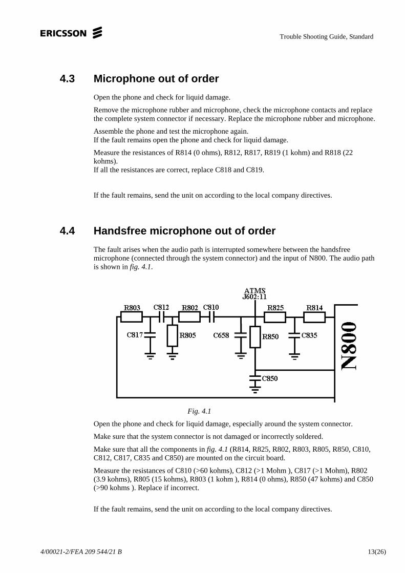
The fault arises when the audio path is interrupted somewhere between the handsfreemicrophone (connected through the system connector) and the input of N800. The audio pathis shown infig. 4.1.
Fig. 4.1
Open the phone and check for liquid damage, especially around the system connector.
Make sure that the system connector is not damaged or incorrectly soldered.
Make sure that all the components infig. 4.1(R814, R825, R802, R803, R805, R850, C810,C812, C817, C835 and C850) are mounted on the circuit board.
Measure the resistances of C810 (>60 kohms), C812 (>1 Mohm ), C817 (>1 Mohm), R802(3.9 kohms), R805 (15 kohms), R803 (1 kohm ), R814 (0 ohms), R850 (47 kohms) and C850(>90 kohms ). Replace if incorrect.
If the fault remains, send the unit on according to the local company directives.

Trouble Shooting Guide, Standard
4/00021-2/FEA 209 544/21 B 14(26)
4.5 Handsfree speaker out of order
The fault arises when the audio path is interrupted somewhere between the output of N800and the handsfree microphone (connected through the system connector). The audio path isshown infig. 4.2.
Fig. 4.2
Open the phone and check for liquid damage, especially around the system connector.
Make sure that the system connector is not damaged or incorrectly soldered.
Measure the resistances of R804 (100 kohms), R640 (82 ohms) and C813 (>1 Mohm).Replace if incorrect.
Measure the resistance at C813, from the side close to V807, to pin 10 if J602 (200 kohms).If the resistance is incorrect, replace R640.
If that does not help there is a foil damage, send the unit on according to the local companydirectives
If the fault remains, send the unit on according to the local company directives.
4.6 The handsfree microphone and speaker out of order
Replace J602.
If the fault remains, send the unit on according to the local company directives.
Trouble Shooting Guide, Standard
4/00021-2/FEA 209 544/21 B 15(26)
5 Display/Illumination Problems
5.1 Type of problem
Insert a fully charged battery into the phone and start it up by pressing the On/Off key.
If the phone does not start, go to chapter 3 (“On/Off ”-problems).
If the display is missing one or more segments, go to section 5.2.
If nothing shows on the display, go to section 5.3.
5.2 Segments are missing.
Change the display unit and adjust the contrast according toSTANDARD REPAIR PACKAGETEST DESCRIPTION R320 and try again.
5.3 Nothing shows on the display
Open the phone and check for liquid damage.
Power up the board and start it up without the display mounted.
Measure the voltages at the display pads (H623).
Pad 1: RES.B 2.75 V
Pad 2: VDD 2.75 V
Pad 3: SDA 2.75 V
Pad 4: SCL 2.75 V
Pad 5: VSS 0 V
Pad 6: VLCD 0 V
If SDA or SCL voltage is missing, check the VDIG voltage (2.70 V).If the VDIG voltage is correct, measure the resistances of R619 (6.8 kohms), R620 (6.8kohms), R615 (0 ohm) and R614 (0 ohms). Also measure the resistance over C675 and C676>1Mohm.
If any of the resistances are incorrect, replace the corresponding component.
If the fault remains, change the display unit and adjust the contrast according toSTANDARDREPAIR PACKAGETEST DESCRIPTION R320 and try again.

Trouble Shooting Guide, Standard
4/00021-2/FEA 209 544/21 B 16(26)
5.4 Background illumination glows faintly or does notwork at all
Open the phone and check for liquid damage.
Clean X750 if needed (fig. 5.1).
Replace the illumination panel.
Note! The illumination is only lit for about 25 seconds, press any key to light it again.
Fig. 5.1
Power up the board and start it by pressing the ON/Off key.
Measure the voltage at pin 6 and 8 of N750 (23 V,fig. 5.1).If the voltage is incorrect, measure the voltage at pin 10 (3.70 V), pin 5 (2.70 V), pin 2 (0.9V) and at pin 4 (1.3 V) of N750.
If the voltage at pin 10 is incorrect, measure the resistances of L750 (3 ohms), C751 (>1Mohms) and the resistance at L750, at the side close to N750, to VBATT (0 ohms).If any of the L750 or C751 resistances are incorrect, replace the corresponding component.
If the resistance from L750 to VBATT is incorrect there is a foil damage, send the unit onaccording to the local company directives
If the voltage at pin 5 is incorrect, send the unit on according to the local company directives
If the voltage at pin 2 or 4 is incorrect, send the unit on according to the local companydirectives
If the voltages are correct, replace L750, C750 and R750.If the fault still remains, replace N750.
If the fault remains after replacing N570, send the unit on according to the local companydirectives.

Trouble Shooting Guide, Standard
4/00021-2/FEA 209 544/21 B 17(26)
6 Capacity/Charging Problems
Make a visual check of the battery connector and the system connector. Replace them ifneeded.
Insert a charged battery into the phone and start it up by pressing the On/Off key. Turn thephone off and connect a charger to the system connector to make sure the fault remains.
Open the phone and check for liquid damage.
Measure the resistance of R710 (0.1 ohm).If the resistance is incorrect, replace R710.
If the resistance is correct, measure the resistance of R711 (0 ohm).If the resistance of R711 is incorrect, replace R711.
If the resistance of R711 is correct, replace V710.
If the fault remains, send the unit on according to the local company directives.
Trouble Shooting Guide, Standard
4/00021-2/FEA 209 544/21 B 18(26)
7 SIM Problems
7.1 What is a SIM-problem
Insert a functional SIM-card and a charged battery into the phone.
If “Wrong card” or “Insert correct card” is displayed on the display when starting thephone it means that the phone is SIM-locked and cannot be repaired at this level.
If the phone displays“Phone lock” on the display it means that the customer has locked thephone with a personal code. The phone is unlocked by the reset part of the functional test.
If “PIN:” or “Enter PIN:” is displayed on the display it means that the SIM-card has beenlocked with a personal code.
There is only a SIM-fault if“card error” is displayed.
7.2 Type of problem
Open the phone and check for liquid damage.
Replace J603.
Measure the resistance from pin 1 to pin 5 of J603 (>1 Mohms).If the resistance is incorrect, replace C734 and C736.If the fault remains, replace C735.
If the voltage at R734 (2.75 V) is incorrect, measure the resistance of R734 (10 kohms).If the resistance is incorrect, replace R734.
Measure the resistance at R733, from the side close to R624, to pin 1 of J603 (15 kohms).If the resistance is incorrect, replace R730.
Measure the resistance at R733, from the side close to R624, to pin 7 of J603 (33 ohms).If the resistance is incorrect, replace R733.
Measure the resistance at R731 (at the side close to R624) to pin 2 of J603 (33 ohms).If the resistance is incorrect, replace R731.
Measure the resistance at R732 (at the side close to R624) to pin 3 of J603 (0 ohm).If it is incorrect, replace R732.
If the fault remains, send the unit on according to the local company directives.

Trouble Shooting Guide, Standard
4/00021-2/FEA 209 544/21 B 19(26)
8 Key Problems
8.1 Type of keyboard problem
Insert a fully charged battery and a SIM-card into the phone. Start it up by pressing theOn/Off key.
If the phone does not start at all, go to chapter 3 (“On/Off ”- problems).
If the phone starts but none of the keys are functional, go to section 8.2.
Press all the keys (including the volume key) to verify which of the keys that are functional.The verification is most easily done this way:
1. Go to “Menu/Settings/Sounds&Alerts/Key sound” and choose “Click”.
2. Press the 1, 2, 3…*, 0, # keys. A clicking sound should be heard and the correspondingsymbol should appear in the display at every key pressed. Then press the “Yes”, “No”,“clr”, “<” and “>” keys. When pressing the “Yes” key the phone should try to connect acall and when pressing the “No” key should make it disconnect the call. The “clr” keymakes the phone erase the symbols in the display one by one while the “<” and “>” keysmake you skim through the menu.
3. Move the volume key up and down, a clicking sound should be heard for each direction.
If the volume key is faulty, go to section 8.3.
8.2 One or more of the keys out of order
Open the phone and check for liquid damage.
Remove the dome foil, clean the pads and mount a new dome foil.
Test the keys as described in 8.1 again.
If the fault remains, send the unit on according to the local company directives.
8.3 Volume key out of order
Replace J820
If the fault remains, send the unit on according to the local company directives.

Trouble Shooting Guide, Standard
4/00021-2/FEA 209 544/21 B 20(26)
9 Alert Problems
9.1 Type of problem
Insert a dummy battery and a SIM-card into the phone and start it up by pressing the On/Offkey. Wait for the phone to get SERV (towards the test instrument or the net).
If the phone does not beep at startup, use the menu to increase the ring volume (not from fullto “step”, as that does not generate any sound).
If the sound is faint or there is no sound at all, go to section 9.2.
When the phone has got SERV and the top indicator flashes green, reduce the battery voltageto 3.20 V. By doing this, the top indicator should start to flash red, the battery indicator showan empty flashing battery and the phone should warn with a beep.
If none of the above mentioned things happen the phone needs a battery calibration.
If the phone beeps and the battery indicator shows an empty flashing battery but the topindicator does not flash red, go to section 9.3.
Use the menu to set the vibrator to On mode.
If the phone does not vibrate when the settings are stored, go to section 9.4.
9.2 Buzzer faint or dead
Open the phone and check for liquid damage.
Make sure that the buzzer H600 is not incorrectly soldered.If the soldering is correct, replace H600.
Assemble the phone and try again as described in 9.1.
Open the phone, power up the board and start it by pressing the On/Off key.
Measure the voltage at pin 3 of H600 (3.70 V).If the voltage is incorrect, replace R603.If that does not help there is a foil damage, send the unit on according to the local companydirectives
Measure the resistance of R651 (1 kohm).If the resistance is incorrect, replace R651.
If the resistance is correct, replace V606.If that does not help, replace V605.

Trouble Shooting Guide, Standard
4/00021-2/FEA 209 544/21 B 21(26)
9.3 Red or green top indicator out of order
Open the phone and check for liquid damage.
Make sure that the double LED H650 is not incorrectly soldered.If the soldering is correct, power up the board and start it by pressing the ON/Off key.
Measure the voltage at pin 4 of H650 (2.70 V).If the voltage is correct, replace H650. Assemble the phone and test as described in 9.1.
If the voltage is incorrect, measure the resistance of R646 (220 ohms).If the resistance is incorrect, replace R646.
If the resistance is correct there is a foil damage, send the unit on according to the localcompany directives
If the fault remains, send the unit on according to the local company directives.
9.4 Vibrator does not work
Open the phone and check for liquid damage.
Fig. 9.1
Make sure that X680 is not dirty, damaged or incorrectly soldered and that the vibratorconnector pads are not dirty or damaged.
Power up the board and start it by pressing the ON/Off key.
Measure the voltage at pin 2 of V621 (3.70 V).If the voltage is incorrect there is a foil damage, send the unit on according to the localcompany directives

Trouble Shooting Guide, Standard
4/00021-2/FEA 209 544/21 B 22(26)
Measure the voltage at pin 3 of V623 (3.70 V).If the voltage is incorrect, measure the resistance of R683 (100 kohms).If the resistance is incorrect, replace R683.
If the voltage is correct, replace V621 and V623. Make sure R627, R628 and C681 aremounted and correctly soldered. Measure the resistance of R682 (1 kohm).If the resistance is incorrect, replace R682.
If the fault remains, send the unit on according to the local company directives.
Trouble Shooting Guide, Standard
4/00021-2/FEA 209 544/21 B 23(26)
10 Data Communication Problems
10.1 Type of problem
If the IRDA device range is too short, go to section 10.2.
If the IRDA communication is not working, go to section 10.3.
10.2 Short range
Open the phone and check for liquid damage.
Make sure that there is no dirt in the IrDA window in the front.
Replace N761.
If the fault remains, go to section 10.3.
10.3 No communication
Check the soldering on N762, resold if necessary. If that does not help, change N762.

Trouble Shooting Guide, Standard
4/00021-2/FEA 209 544/21 B 24(26)
11 Other Problems
11.1 RTC
11.2 Figure out the problem
Start the phone with a SIM-card and a fully charged battery. Set the correct time. Remove thebattery and reinsert it after one minute.
If the phone clock says 00:00, go to section 11.2.
Compare to the correct time.
If the clock is halted or speeding, go to section 11.3.
11.3 The clock says 00:00 after reinserting the battery
Open the phone and make sure that the backup capacitor (C720) is correctly soldered.
If it is, replace it. Assemble the phone, start it up and set the correct time. Wait a few minutesfor the backup capacitor to charge. Remove the battery and reinsert it after one minute. Makesure that the fault has been solved (the backup capacitor needs 20 minutes of charging beforereaching full capacity). Compare to the correct time.
If the clock is halted or speeding, go to section 11.3.
11.4 The clock is halted or speeding
Open the phone and check the soldering of B600.If they are correct, replace B600.
If that does not help, replace C690 and C691.
Assemble the phone and compare to the correct time.
If the fault remains, send the unit on according to the local company directives.

Trouble Shooting Guide, Standard
4/00021-2/FEA 209 544/21 B 25(26)
12 Software Problems
If there are problems with the response of the key board commands and/or spelling errors inthe menu, that are not related to mechanical damage, upgrade the phone with the latestsoftware.
If the fault still remains, send the unit on according to the local company directives.
Trouble Shooting Guide, Standard
4/00021-2/FEA 209 544/21 B 26(26)
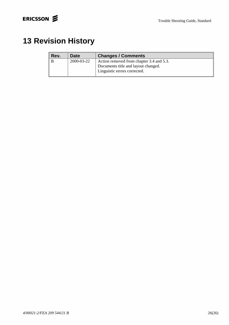
13 Revision History
Rev. Date Changes / CommentsB 2000-03-22 Action removed from chapter 3.4 and 5.3.
Documents title and layout changed.Linguistic errors corrected.