Trouble Shooting Guide - Plumbing HVAC Distributor in CT · 2 Outdoor Error Error Code Contents...
32
1 Trouble Shooting Guide Indoor Error Error Indicator • The function is to self-diagnoisis airconditioner and express the troubles identifically if there is any trouble. • If more than two troubles occur simultaneously, primarily the highest trouble fo error code is expressed. • After error occurrence, if error is released, error LED is also released simultaneously. • To operate again on the occurrence of error code, be sure to turn off the power and then turn on. • Having or not of error code is different from Model. Error Code Contents Case of Error 01 Indoor Room sensor error Indoor Room Temperature Sensor Open/short 02 Indoor in-piping sensor error Indoor Inlet Pipe Sensor open/short 03 Remote controller error Between Indoor and Remote controller communication poorly 04 Drain Pump error Malfunction of drain pump 05 Communcation error between in and out Between Indoor and Outdoor communication poorly 06 Indoor Out-Piping sensor error Indoor Outlet Pipe Sensor open/short 07 Differnt mode operation Different operation mode 09 EEPROM Check Sum Error Checksum mismatching 10 Indoor BLDC Fan Lock Indoor Fan is not operating
Transcript of Trouble Shooting Guide - Plumbing HVAC Distributor in CT · 2 Outdoor Error Error Code Contents...

1
Trouble Shooting Guide
Indoor Error
Error Indicator
• The function is to self-diagnoisis airconditioner and express the troubles identifically if there is any trouble.• If more than two troubles occur simultaneously, primarily the highest trouble fo error code is expressed.• After error occurrence, if error is released, error LED is also released simultaneously.• To operate again on the occurrence of error code, be sure to turn off the power and then turn on.• Having or not of error code is different from Model.
ErrorCode Contents Case of Error
01 Indoor Room sensor error Indoor Room Temperature Sensor Open/short
02 Indoor in-piping sensor error Indoor Inlet Pipe Sensor open/short
03 Remote controller error Between Indoor and Remote controller communication poorly
04 Drain Pump error Malfunction of drain pump
05 Communcation error between in and out Between Indoor and Outdoor communication poorly
06 Indoor Out-Piping sensor error Indoor Outlet Pipe Sensor open/short
07 Differnt mode operation Different operation mode
09 EEPROM Check Sum Error Checksum mismatching
10 Indoor BLDC Fan Lock Indoor Fan is not operating
2
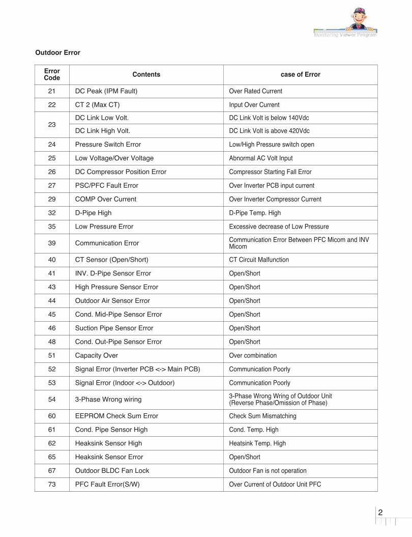
Outdoor Error
ErrorCode Contents case of Error
21 DC Peak (IPM Fault) Over Rated Current
22 CT 2 (Max CT) Input Over Current
23DC Link Low Volt. DC Link Volt is below 140Vdc
DC Link High Volt. DC Link Volt is above 420Vdc
24 Pressure Switch Error Low/High Pressure switch open
25 Low Voltage/Over Voltage Abnormal AC Volt Input
26 DC Compressor Position Error Compressor Starting Fall Error
27 PSC/PFC Fault Error Over Inverter PCB input current
29 COMP Over Current Over Inverter Compressor Current
32 D-Pipe High D-Pipe Temp. High
35 Low Pressure Error Excessive decrease of Low Pressure
39 Communication Error Communication Error Between PFC Micom and INVMicom
40 CT Sensor (Open/Short) CT Circuit Malfunction
41 INV. D-Pipe Sensor Error Open/Short
43 High Pressure Sensor Error Open/Short
44 Outdoor Air Sensor Error Open/Short
45 Cond. Mid-Pipe Sensor Error Open/Short
46 Suction Pipe Sensor Error Open/Short
48 Cond. Out-Pipe Sensor Error Open/Short
51 Capacity Over Over combination
52 Signal Error (Inverter PCB <-> Main PCB) Communication Poorly
53 Signal Error (Indoor <-> Outdoor) Communication Poorly
54 3-Phase Wrong wiring 3-Phase Wrong Wring of Outdoor Unit(Reverse Phase/Omission of Phase)
60 EEPROM Check Sum Error Check Sum Mismatching
61 Cond. Pipe Sensor High Cond. Temp. High
62 Heaksink Sensor High Heatsink Temp. High
65 Heaksink Sensor Error Open/Short
67 Outdoor BLDC Fan Lock Outdoor Fan is not operation
73 PFC Fault Error(S/W) Over Current of Outdoor Unit PFC

3
10k
Check the resistance Check the voltage
V
2.5Vdc
01
02
06
Indoor air sensor
Indoor inlet pipe sensor
Indoor outlet pipe sensor
• Open / Short• Soldered poorly• Internal circuit error
• Open / Short• Soldered poorly• Internal circuit error
• Open / Short• Soldered poorly• Internal circuit error
Normal resistor : 10KΩ/ at 25°C (Unplugged)Normal voltage : DC 2.5V / at 25°C (plugged)
Normal resistor : 5KΩ/ at 25°C (Unplugged)Normal voltage : DC 2.5V / at 25°C (plugged)
Normal resistor : 5KΩ/ at 25°C (Unplugged)Normal voltage : DC 2.5V / at 25°C (plugged)
Displaycode
Title Cause of error Check point & Normal condition
Check Point1. Unplug the sensor on Indoor unit PCB.
2. Estimate the resistance of each sensor.
3. If the resistance of the sensor is 10KΩ/ 5KΩ at 25°C, then sensor is normal.
4. If the resistance of the sensor is 0 KΩ or ∞, then sensor is abnormal. � Change the sensor.
5. Plug the sensor on Indoor unit PCB and Power ON.
6. Estimate the voltage of each sensor.
7. If the voltage of the sensor is 2.5Vdc at 25°C, then sensor is normal.
8. If the resistance of the sensor is 0 or 5Vdc, then sensor is abnormal. � Repair or Change the PCB.

4
Check the Volt.
Indoor Unit
V
12Vdc
12V S GND
Check the Volt.
Wired R/C
V
12Vdc
12V S GND
03Communication
Wired R/C• Open / Short• Wrong connection
• Connection of wire • Main PCB Volt. DC12V• Noise interference
Displaycode
Title Cause of error Check point & Normal condition
Check Point1. Check the wire connection. (Open / Short) � Repair the connection
2. Check the soldering state of connector. (Soldered poorly) � Repair or Change the PCB.
3. Check the volt. Of main PCB power source. (DC 12V) � Repair or Change the main PCB.
4. Check the installation of wired remote controller. (Noise interference) � Adjust the state of installation
5
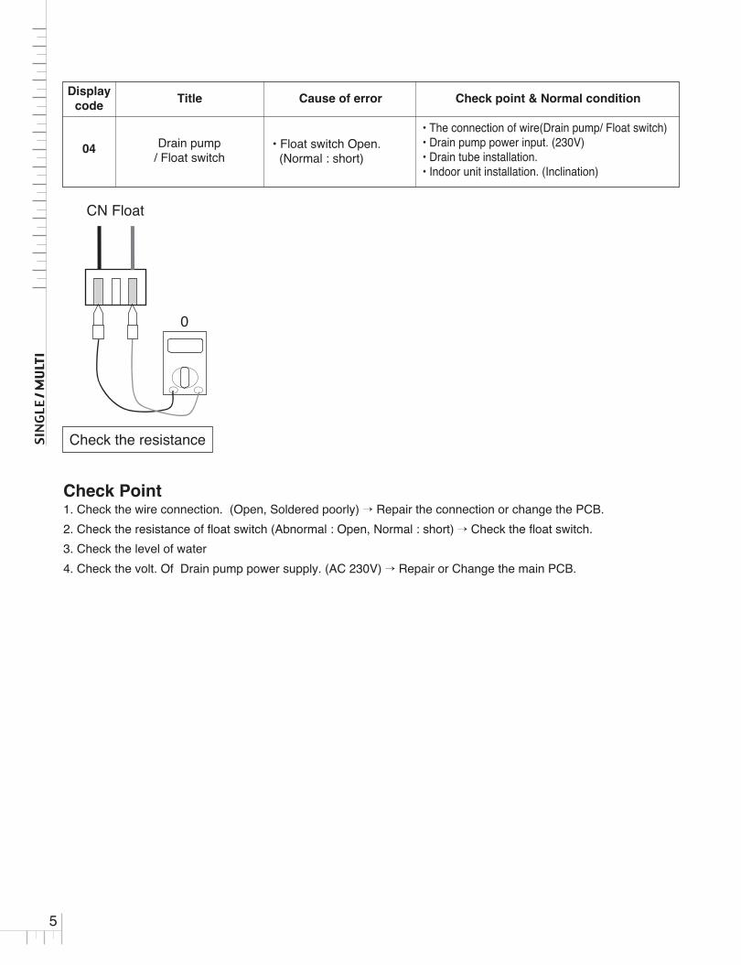
Check the resistance
0
CN Float
04 Drain pump/ Float switch
• Float switch Open.(Normal : short)
• The connection of wire(Drain pump/ Float switch) • Drain pump power input. (230V)• Drain tube installation.• Indoor unit installation. (Inclination)
Displaycode
Title Cause of error Check point & Normal condition
Check Point1. Check the wire connection. (Open, Soldered poorly) � Repair the connection or change the PCB.
2. Check the resistance of float switch (Abnormal : Open, Normal : short) � Check the float switch.
3. Check the level of water
4. Check the volt. Of Drain pump power supply. (AC 230V) � Repair or Change the main PCB.

6
07 Different Operation Mode• One of Indoor Unit oper-
ate cooling Another Unitoperate heating
• At the same time, this model cannot use cool andheating mode
Displaycode
Title Cause of error Check point & Normal condition
Check Point1. Check another indoor model operation mode
2. Operating the same mode with the first operated indoor unit
3. Clearing the "CH07"Press the on/off button or mode change button and matching the indoor unit mode same as the first operatedindoor unit

7
09 Indoor EEPROM CheckSum Error • Check sum error
1. Check the poor soldering2. Check the insertion condition of the EEPROM3. Check the PCB Connection
Displaycode
Title Cause of error Check point & Normal condition
Check Point1. Check the EEPROM Direction
2. If the EEPROM value & the Program value are not matched, the Code is Displayed
3. After Checking the connection and Insertion, replace the PCB or Option PCB

8
10 Indoor BLDC Fan MotorLock
The Fan is not operatedproperly Check the Indoor fan locking
Displaycode
Title Cause of error Check point & Normal condition
Check PointCheck the PCB during the Power on
1. Check the Voltage Red line to Black line� The Voltage is about [input voltage x 1.414]� if the Voltage does not come with the above Voltage,� Check the power input� Replace the PCB & Motor
2. Check the Voltage Black line to White� the Voltage is DC 15V� Check the Power input� Replace the motor
Check the Motor
1. Check the shaft� if the shaft is not turn smoothly, the Motor Power IC is defected� replace the motor
2. Check the motor resistance(if the shaft is turn smoothly, check the resistance)� Check Red line to Black line, Blue line to Black line � The resistance should infinite� replace the motor
Tester
Fan motorconnector
Yellow
Blue
White
Black Red

9
Displaycode
Title Cause of error Check point & Normal condition
21DC Peak(IPM Fault)
• Compressor blocked• Disconnection/shortcircuit
inside compressor• Over load operation
(Outdoor fan constraint,screened, blocked)
• Burned parts inside PCB
• Check compressor constraint• Check compressor wire open/short• Check compressor insulation damage• Check outdoor fan constraint / screened / flow
structure• Check if IPM burned
WARNINGBefore checking PCB or each outdoor electric parts, wait for 3 minutes after the power is off. When measuring at standby stateof power supply, after checking the measurement mode of the meter, be careful of the short-circuits with other parts.
Is installationcondition normal?
1. Check Pipe clogging/distortion2. Check Covering (Indoor/Outdoor Unit)3. Check EEV connector assemble condition/normal operation4. Check refrigerant pressure→ Reassemble or manage if abnormality found
1. Check resistance between each terminal of compressor (0.438~0.628±7%)2. Check insulation resistance between compressor terminal and pipe (over 2MΩ)→ Replace compressor if abnormality found
Are the resistanceBetween each phase and
insulation resistance of Inverter compressor normal?
1. Check inverter PCB assembly U,V,W connector connection condition2. Check wire disconnection and wiring3. Check compressor terminal connection condition (bad contact)→ Reassemble if abnormality found
Is compressorWire connection
condition normal?
Check inverter PCB assembly IPM normality→ Replace inverter PCB assembly
Is inverter PCBassembly normal?
Recheck power andinstallation condition
Yes
Yes
No
Yes
No
No
Yes
No

10
Displaycode
Title Cause of error Check point & Normal condition
22CT 2(Max CT)
• Input voltage error(lowvoltage)
• Over load operation(Outdoor fan constraint,screened, blocked)
• Burned parts inside PCB
• Check input voltage• Check outdoor fan canstraint / screened / flow
structure• Check PCB current sensor parts
WARNINGBefore checking PCB or each outdoor electric parts, wait for 3 minutes after the power is off. When measuring at standby stateof power supply, after checking the measurement mode of the meter, be careful of the short-circuits with other parts.

11
Displaycode
Title Cause of error Check point & Normal condition
23 DC Link High / Low Volt
• DC Link Voltage is above420Vdc
• DC Link Voltage is below140Vdc
• Check Input Voltage• Check PCB DC Link voltage sensor parts
Recheck power andinstallation condition
Yes
WARNINGBefore checking PCB or each outdoor electric parts, wait for 3 minutes after the power is off. When measuring at standby stateof power supply, after checking the measurement mode of the meter, be careful of the short-circuits with other parts.

12
24 Pressure Switch Error • Low / High pressS/W open.
• Check the connection CN_L/PRESS,H/PRESS• Check the components.
Displaycode
Title Cause of error Check point & Normal condition
Yes
Is high/low pressure switchconnector connected
to PCB?*
Connect securely
Is high/low pressure switchconnector short
during off time?**
• Check fan locking• Remove blockings around heat exchanger• Maintain distance between outdoor unit and the wall• Check pipe folding and abnormality• Check SVC valve lock
• Remedy : remove cause of error
Replace high/low pressure switch
Yes
No
Is the unit properly installed?
Yes
No
Yes
No
Check pipe is blocked ornot and take measure
Is this error appearedagain after reset?
Re-check momentary problem or not
Yes
No
Is high pressuremore than 4200kPa
or low pressure less than 30kPaat manifold gauge?
Replace PCB No

13
Displaycode
Title Cause of error Check point & Normal condition
25 Low Voltage/Over VoltageInput voltage is over limitedvalue of the product (140Vor less, 300V or more)
1. Input voltage abnormal (R-S-T)2. Outdoor unit main PCB assembly damage
(input voltage sensing part)
Recheck power andinstallation condition
Are there any power wire connections normal?
1. Check L/N/G wiring conditions→ Rewire them if abnormality found.
Is input voltage normal?
CheckR~S/S~T/T~R phase voltage is 220V 10%→ Check connection condition and wiring if power is abnormal
Is mainPCB assembly power connection normal?
Check connection between main PCB assembly and bridge diode(misconnection, disconnection)→ wiring again if abnormality found
Monitoring PCB LEDdisplay error
Replace main PCB assembly.
Yes
Yes
No
Yes
No
No
Yes
No
WARNINGBefore checking PCB or each outdoor electric parts, wait for 3 minutes after the power is off. When measuring at standby stateof power supply, after checking the measurement mode of the meter, be careful of the short-circuits with other parts.

14
Displaycode
Title Cause of error Check point & Normal condition
26DC Compressor PositionError
• Compressor Locking• Overload operation
(Outdoor fan constraint,screened, blocked)
• Burned parts insidePCB(IPM)
• Burned PCB phase currentsensing circuit parts
• Check compressor locking• Compressor wire open/short• Check compressor insulation damage• Check outdoor fan constraint / screened / flow
structure• Check if IMP burned (refer to CH21)• Check on-PCB current sensing circuit parts
Recheck power andinstallation condition
Yes
WARNINGBefore checking PCB or each outdoor electric parts, wait for 3 minutes after the power is off. When measuring at standby stateof power supply, after checking the measurement mode of the meter, be careful of the short-circuits with other parts.

15
27 PSC/PFC Fault Error
• Overload operation(Outdoor fan constraint,screened, blocked)
• Wrong application ofReactor Spec.
• Burned PCB internalparts (PSC Module)
1. Overload operation (Pipe clogging/Covering/EEVdefect/Ref. overcharge)
2. Compressor damage (Insulation damage/Motordamage)
3. Input voltage abnormal (L,N)4. Power line assemble condition abnormal5. Inverter PCB assembly Damage (input current
sensing part)
Displaycode
Title Cause of error Check point & Normal condition
1.Check Pipe clogging/distortion2.Check Covering (Indoor/Outdoor Unit)3.Check EEV connector assemble condition/normal operation4.Check refrigerant pressure→ Reassemble or manage if abnormality found
Is installationcondition normal?
Is compressorWire connection
condition normal?
1.Check inverter PCB assembly U,V,W connector connection condition2.Check wire disconnection and wiring3.Check compressor terminal connection condition(bad contact)→ Reassemble if abnormality found
Is AC input Wire connectioncondition normal?
1.Check L,N connection condition2.Check wire disconnection and wiring→ Reassemble if abnormality found
Is inverter PCB assemblynormal?
Recheck power andinstallation condition
CheckL~N phase voltage is 230V ± 15%→ Check connection condition and wiring if power is abnormal
Is input voltage normal?
Check inverter PCB assembly PFCM normality→ Replace inverter PCB assembly
Yes
Yes
No
Yes
No
No
Yes
Yes
No
No
WARNINGBefore checking PCB or each outdoor electric parts, wait for 3 minutes after the power is off. When measuring at standby stateof power supply, after checking the measurement mode of the meter, be careful of the short-circuits with other parts.

16
29Inverter compressor over
currentInverter compressor inputcurrent is over 30A
1. Overload operation (Pipe clogging/Covering/EEV defect/Ref. over-charge)
2. Compressor damage(Insulation damage/Motordamage)
3. Input voltage low4. ODU inverter PCB assembly damage
Displaycode
Title Cause of error Check point & Normal condition
Is installation condition normal?
Recheck power andinstallation condition
1. Check Pipe clogging/distortion2. Check Covering (Indoor/Outdoor Unit)3. Check EEV connector assemble condition/normal operation4. Check refrigerant pressure→ Reassemble or manage if abnormality found
Is input voltage normal?
Check L~N phase is 230V±15%→ Check connection condition and wiring if power is abnormal
Is inverter PCB assembly normal?
Check inverter PCB assembly IPM normality→ Replace inverter PCB assembly
Are the resistanceBetween each phase
and insulation resistance of Inverter compressor normal?
1. Check resistance between each terminal of compressor (0.438~0.628±7%)2. Check insulation resistance between compressor terminal and pipe (over 2MΩ)→ Replace compressor if abnormality found
Is compressor Wire connection condition normal?
1. Check inverter PCB assembly U,V,W connector connection condition2. Check wire disconnection and wiring3. Check compressor terminal connection condition (bad contact)→ Reassemble if abnormality found
Yes
Yes
No
No
Yes
Yes
No
No
Yes
No
WARNINGBefore checking PCB or each outdoor electric parts, wait for 3 minutes after the power is off. When measuring at standby stateof power supply, after checking the measurement mode of the meter, be careful of the short-circuits with other parts.

17
Displaycode
Title Cause of error Check point & Normal condition
32 D-Pipe High
• Overload operation(Outdoor fan constraint,screened, blocked)
• Refrigerant leakage(insufficient)
• Poor INV CompDischarge sensor
• LEV connector displaced/ poor LEV assembly
• Check outdoor fan constraint/ screened/ flowstructure
• Check refrigerant leakage• Check if the sensor is normal• Check the status of EEV assembly
CN- DISCHARGE
Replace the Thermistor
Yes
WARNINGBefore checking PCB or each outdoor electric parts, wait for 3 minutes after the power is off. When measuring at standby stateof power supply, after checking the measurement mode of the meter, be careful of the short-circuits with other parts.

18
Displaycode
Title Cause of error Check point & Normal condition
35 Low Presser ErrorExcessive decrease of lowpressure
• Defective low pressure sensor• Defective outdoor/indoor unit fan• Refrigerant shortage/leakage• Deformation because of damage of refrigerant pipe• Defective indoor / outdoor unit EEV• Covering / clogging (outdoor unit covering during
the cooling mode / indoor unit filter clogging dur-ing heating mode)
• SVC valve clogging• Defective outdoor unit PCB• Defective indoor unit pipe sensor
Is service valveopened?
Open service valve
Are communication cable/piping normal?
Is amount ofrefrigerant normal?
[refer refrigerant part]
Is fan normal?(in heating outdoor fan,in cooling indoor fan)
Adjust the amount of refrigerant (Additive charge)
check communication / piping correction.
Weld / reconnect the crackedportion and recharge refrigerant
Check and replace related parts(error 105~108 reference)
Is strainer Ok?* Replace the strainer
Replace the pressure sensor
Check indoor / outdoor unit LEVCheck Indoor unit PCBCheck indoor / outdoor unitinstallation conditions
Are the valuesof manifold and low pressure
sensor same?( Is the low pressure value
actually low?)
Is there pipe crackor trace of refrigerant
leakage?
* If the temperature difference between inlet and outlet of strainer is so large that frost or ice formation can be seen or confirmed then clogging of strainer should be checked (Notice: it is not full ice forming of strainer, in case that there is not at inlet portion but at outlet portion)
Yes
Yes
No
Yes
No
No
Yes
Yes
Yes
No No
No
Yes
No

19
39 Communication ErrorCommunication ErrorBetween PFC Micomand INV Micom.
1. Micom defect/Circuit defect2. Different Micom S/W Version3. ODU inverter PCB assembly damage
Displaycode
Title Cause of error Check point & Normal condition
� Error Diagnosis and Countermeasure Flow Chart
Is Inverter PCBassembly normal? Replace inverter PCB assembly
Is PFC Micom& INV Micom S/W Program
normal? Upgrade Micom Program
Recheck power andinstallation condition
Yes
Yes
No
No

20
Displaycode
Title Cause of error Check point & Normal condition
40 CT Sensor (Open/short)• PCB sensing circuit part
burned• Check power input connector, Comp output
current sensing circuit
Is AC input currentsensing part normal?
• Check voltage measurement on the input current at the power-on standby state DC 0V ± 0.2V
• Remedy : remove cause of error
• DC voltage measurement at the measurement point in figure 2 at power-on standby state -> measured value : within 2.5V ± 0.2V
• Remedy : remove cause of error
Is the Comp phaseCurrent sensor part normal?
Recheck powerand installation condition
Yes
WARNINGBefore checking PCB or each outdoor electric parts, wait for 3 minutes after the power is off. When measuring at standby stateof power supply, after checking the measurement mode of the meter, be careful of the short-circuits with other parts.

21
41
44
45
46
48
D-pipe sensor (Inverter)
Air sensor
Condenser Mid-pipe sensor
Suction Pipe sensor
Condenser Out-pipe sensor
• Open / Short• Soldered poorly• Internal circuit error
• Open / Short• Soldered poorly• Internal circuit error
• Open / Short• Soldered poorly• Internal circuit error
• Open / Short• Soldered poorly• Internal circuit error
• Open / Short• Soldered poorly• Internal circuit error
• Normal resistor : 200KΩ / at 25°C (Unplugged)
• Normal resistor : 10KΩ / at 25°C (Unplugged)
• Normal resistor : 5KΩ / at 25°C (Unplugged)
• Normal resistor : 5KΩ / at 25°C (Unplugged)
• Normal resistor : 5KΩ / at 25°C (Unplugged)
Displaycode
Title Cause of error Check point & Normal condition
Is sensor PCB connected to main PCB
correctly?
• Connect sensor PCB to main PCB correctly
• Remedy : reassemble the sensor
• Check the status of the PCB connector assembly• Check the status of the sensor assembly
• Remedy : reassemble the sensor
Is the sensor properlyassembled?
• Check if the sensor is disconnected• Check if the sensor is burned : measure the resistance• Check if the sensor insulation is damaged
• Remedy : remove cause of error
Is the sensor normal?
Recheck power and installation condition
Yes
22
Displaycode
Title Cause of error Check point & Normal condition
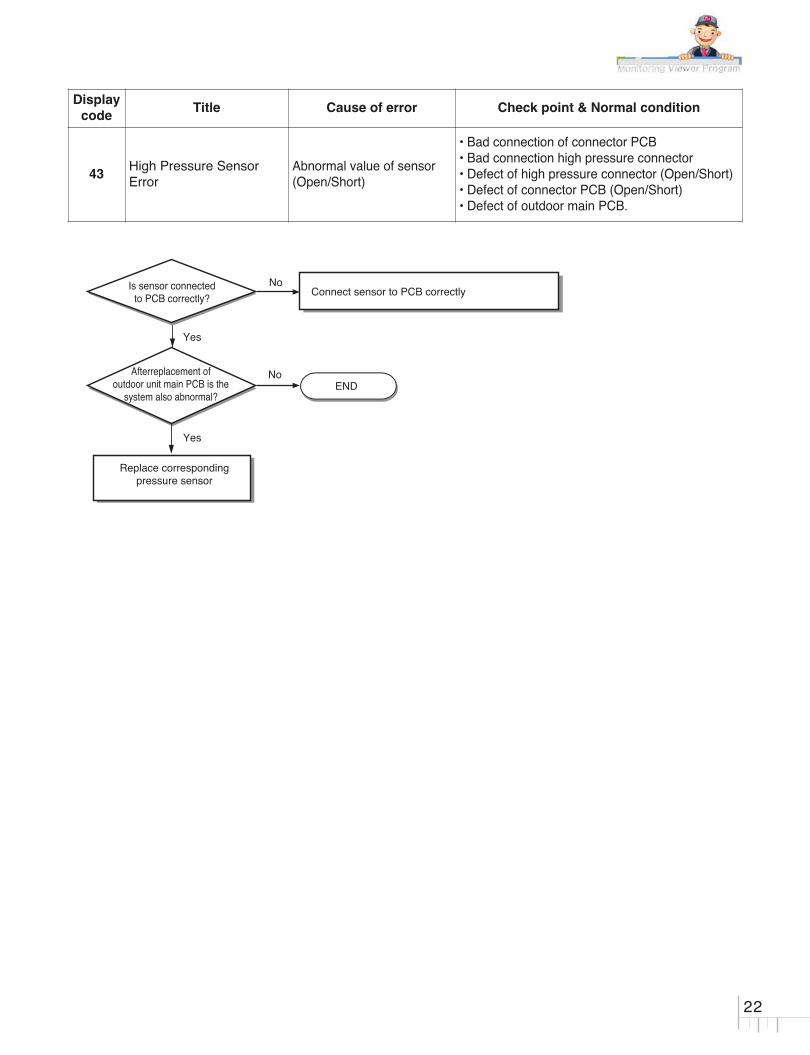
43High Pressure SensorError
Abnormal value of sensor(Open/Short)
• Bad connection of connector PCB• Bad connection high pressure connector• Defect of high pressure connector (Open/Short)• Defect of connector PCB (Open/Short)• Defect of outdoor main PCB.
Is sensor connectedto PCB correctly?
Connect sensor to PCB correctly
Replace correspondingpressure sensor
ENDAfterreplacement of
outdoor unit main PCB is thesystem also abnormal?
Yes
Yes
No
No

23
Check Point• CH 51
1. Check the indoor unit capacity.
2. Check the combination table.
Displaycode
Title Cause of error Check point & Normal condition
51 Capacitor Over • Over capacity Combination• Check the indoor unit capacity.• Check the combination table.

24
52Signal Error
(Inverter PCB <-> MainPCB)
Main controller of Masterunit of Master unit canʼtreceive signal frominverter controller
1. Power cable or transmission cable is not connected
2. Defect of outdoor Main fuse/Noise Filter3. Defect of outdoor Main / inverter PCB
Displaycode
Title Cause of error Check point & Normal condition
Is transmission LED (Yellow) of inverter
compressor PCB on?
Is transmission cableconnected correctly?
Replace invertercompressor PCB
Yes
Yes
Yes
No
Replace MAIN PCB
Re-connect transmission cable
Replace inverter compressor PCB
Replace noise filter or fuse
Is MAIN PCB normal?
Yes
No
No Is noise filter or fusenormal?
No
Check Point- Check the Transmission connector and LED (Main & Inverter)
<MAIN PCB> <Inverter PCB>

25
Displaycode
Title Cause of error Check point & Normal condition
5 / 53Signal Error(Indoor � Outdoor)
• No power on indoor unit• Indoor/outdoor unit
Power connectionerror/communicationerror caused by externalnoise
• Indoor/outdoor unit com-munication circuit partsburned
• Check indoor unit power status• Check indoor/outdoor unit
power/communication line disconnection• Check the status of indoor/outdoor unit ground
connections• Check if outdoor unit communication parts are
burned
Recheck powerand installation condition
Yes
WARNINGBefore checking PCB or each outdoor electric parts, wait for 3 minutes after the power is off. When measuring at standby stateof power supply, after checking the measurement mode of the meter, be careful of the short-circuits with other parts.

26
54 3-Phase Wrong wiring• 3-phase wrong wiring of
outdoor unit (ReversePhase /omission ofphase)
• Abnormal Main PCB• No connection of CN_Phase• Changed R, S, T connection order
Displaycode
Title Cause of error Check point & Normal condition
R~S/S~T/T~R phase voltage is 380V æ 10%R~N/S~N/T~N phase voltage is 220V æ10%Check connection condition and wiring if power is abnormal.
1. Check the Connection condition of PCBs 1) Input &Output (R,S,T,N) wire Connection of Noise Filter. 2) Check reverse connecting and non connecting for CN-L1(R), CN-L2(S), CN-L3(T) of the Inverter PCB 3) Check the CN-AC-220V Connector of the Inverter PCB and T-N connector of the Noise Filter2. Check the connection or damage of power source fuses.
Is PCB connectionNormal?
Is input voltage normal ?
Recheck power andinstallation condition
Yes
Yes
No
No
WARNINGBefore checking PCB or each outdoor electric parts, wait for 3 minutes after the power is off. When measuring at standby stateof power supply, after checking the measurement mode of the meter, be careful of the short-circuits with other parts.

27
Displaycode
Title Cause of error Check point & Normal condition
60EEPROM Check SumError
• Outdoor unit PCB EEPROM misapplied
• Outdoor unit PCB EEPROM poor assmbly
EEPROM assembly
<EEPROM Direction Check Point>
• Inspecting Outdoor EEPROM Assembly Status1. Check the consistency of the EEPROM’s direction inserted in the PCB and the EEPROM marking.
Replace EEPROM
Yes
WARNINGBefore checking PCB or each outdoor electric parts, wait for 3 minutes after the power is off. When measuring at standby stateof power supply, after checking the measurement mode of the meter, be careful of the short-circuits with other parts.

Displaycode
Title Cause of error Check point & Normal condition
61 Cond. Pipe Sensor High
• Overload operation(Outdoor fan constraint,screened, blocked)
• Outdoor unit heatexchanger contaminated
• EEV connector displaced/ poor EEV assembly
• Poor Cond. Pipe sensorassembly / burned
• Check outdoor fan constraint / screened / flowstructure
• Check if refrigerant overcharged• Check the status of EEV assembly• Check the status of sensor assembly / burn
Replace the Thermistor
Yes
WARNINGBefore checking PCB or each outdoor electric parts, wait for 3 minutes after the power is off. When measuring at standby stateof power supply, after checking the measurement mode of the meter, be careful of the short-circuits with other parts.
28

29
Displaycode
Title Cause of error Check point & Normal condition
62 Heatsink Sensor HighInverter PCB heatsink tem-perature is over 85°C
• ODU fan locking• Heatsink assembly of INV PCB assemble condi-
tion abnormal• Defect of temperature sensing circuit part defect
of INV PCB
Is installation condition normal ?
1. Check fan locking2. Check covering of heat exchanger3. Check distance between ODU and obstacles4. Check pipe distortion and abnormality5. Check service valve is opened→ Eliminate causes for abnormal condition
Check resistance between NO.14 pin andNO.16 pin of IPM module• 85kΩ ± 6.3% (at 25℃)• Replace main PCBA it abnormality found
Is assemble condition of INV PCB heatsink
normal ?
Is PCB temperature sensing part normal ?
Check assemble condition between INV PCB heatsink andPFC & IPM module ’ Reassemble if abnormality found
Recheck installation conditionand connection of Heat sink
Yes
Yes
No
Yes
No
No

Displaycode
Title Cause of error Check point & Normal condition
65 Heatsink Sensor ErrorInverter PCB heatsink sen-sor is open or short
• ODU fan locking• Heatsink assembly of INV PCB assemble
condition abnormal• Defect of temperature sensing circuit part defect
of INV PCB
Is installation condition normal ?
1. Check fan locking2. Check covering of heat exchanger3. Check distance between ODU and obstacles4. Check pipe distortion and abnormality5. Check service valve is opened→ Eliminate causes for abnormal condition
Check resistance between NO.14 pin and NO.16 pin of IPM module• 85kΩ ± 6.3% (at 25℃)• Replace main PCBA it abnormality found
Is assemblecondition of INV PCB
heatsink normal ?
Is PCB temperature sensing part normal ?
Check assemble condition between INV PCB heatsink andPFC & IPM module→ Reassemble if abnormality found
Recheck installation conditionand connection of Heat sink
Yes
Yes
No
Yes
No
No
30

31
Displaycode
Title Cause of error Check point & Normal condition
67 Outdoor BLDC Fan Lock
Fan RPM is 10RPM or lessfor 5 sec. when ODU fanstarts or 40 RPM or lessafter fan starting.
• ODU fan locking• Heatsink assembly of INV PCB assemble condi-
tion abnormal• Defect of temperature sensing circuit part defect
of INV PCB
Is ODU Fan Motor Assemble condition normal?
Recheck power andinstallation condition
Check ODU Fan Motor assemble condition and fan locking→ Reassemble or replace if abnormality found
Is ODU Fan Motornormal?
1. Set the multi tester to diode mode.2. Check voltage between 1pin and 4pin of Fan Motor (1 0.2V)3. Replace Inverter PCB if abnormality found.
Is wire connection of ODU Fan Motor
wire normal?
Check wiring between OUD fan motor and Inverter PCB( Check if Hall Senor and Motor output terminal color is matched)→ Reassemble if abnormality found
Is connector PCBassembly normal? Replace connector PCB assembly
Is main PCB assemblynormal?
Replace main PCB assembly
No
Yes
Yes
No
Yes
Yes
Yes
No
No
No
Check Point1. Check voltage between 1pin and 4pin of Fan Mortor connector (Tester diode mode)
2. Voltage value should be in 1V ±0.2V.

73 PFC Fault Error (S/W)Inverter PCB input powercurrent is over 48A(peak)for 2ms
1. Overload operation (Pipe clogging/Covering/EEVdefect/Ref.overcharge)
2. Compressor damage (Insulation damage/Motor damage)
3. Input voltage abnormal (L, N)4. Power line assemble condition abnormal5. Inverter PCB assembly damage
(input current sensing part)
Displaycode
Title Cause of error Check point & Normal condition
1.Check Pipe clogging/distortion2.Check Covering (Indoor/Outdoor Unit)3.Check EEV connector assemble condition/normal operation4.Check refrigerant pressure → Reassemble or manage if abnormality found
1.Check inverter PCB assembly U,V,W connector connection condition2.Check wire disconnection and wiring3.Check compressor terminal connection condition(bad contact) → Reassemble if abnormality found
1.Check L,N connection condition2.Check wire disconnection and wiring → Reassemble if abnormality found
Check L~N phase voltage is 230V ± 15%→ Check connection condition and wiring if power is abnormal
Check inverter PCB assembly IPM normality → Replace inverter PCB assembly
NoIs installation condition normal?
Is compressorWire connection
condition normal?
Is AC input Wire connectioncondition normal?
Is inverter PCB assemblynormal?
Yes
Yes
No
Recheck power and installation condition
Yes
Yes
Yes
No
No
NoIs input voltage normal?
32