TROUBLE SHOOTING - Caltrans - California Department of …€¦ · · 2014-01-31OZONE GENERATOR...
24
TROUBLE SHOOTING OZONE GENERATOR When trouble shooting, there are four major areas to look at to determine the location of any problem: 1. The Lamp Cartridge indicator light on tf:tQ. front of the unit, which should remain ON 'Nhile the unit is aperating.:. 2. The sound or vibration on ttte AOUAZONE purifier, which would indicate that the air pump is working. 3. The condition of the water. 4. Ozone bubbles in the water. SITUATION: Indicator light OFF 1. Check GFCI to see if it has tripped. 2. Check lamp connection. 3. Check for blown lamp. 4. Check power supply. SITUATION: Ozone not present in water 1. Check for clean filter (a dirty filter will cause a low flow of ozone). 2. Check for clogged jet ( debris in line ). 3. Check for kinked delivery line or blocked check valve. 4. Check diffuser stone to see that it has not been fowled. SITUATION: Cloudy water with ozone present. 1. Check pH balance 2. Clean filter 3. Use shock treatment to rid water of excessive contaminants. 4. Drain and clean tanks.
Transcript of TROUBLE SHOOTING - Caltrans - California Department of …€¦ · · 2014-01-31OZONE GENERATOR...

TROUBLE SHOOTING
OZONE GENERATOR
When trouble shooting there are four major areas to look at to determine the location of any problem
1 The Lamp Cartridge indicator light on tftQ front of the unit which should remain ON Nhile the unit is aperating
2 The sound or vibration on ttte AOUAZONE purifier which would indicate that the air pump is working
3 The condition of the water 4 Ozone bubbles in the water
SITUATION Indicator light OFF
1 Check GFCI to see if it has tripped 2 Check lamp connection 3 Check for blown lamp 4 Check power supply
SITUATION Ozone not present in water
1 Check for clean filter (a dirty filter will cause a low flow of ozone) 2 Check for clogged jet ( debris in line ) 3 Check for kinked delivery line or blocked check valve 4 Check diffuser stone to see that it has not been fowled
SITUATION Cloudy water with ozone present
1 Check pH balance 2 Clean filter 3 Use shock treatment to rid water of excessive contaminants 4 Drain and clean tanks
t EC RC u_ L1I 0 l ozone system INSTALLATION AND OWNERS MANUAL
ultraviolet
CS-1400 amp UV-2800middot qzone generator PO BOX 15330 SAN LUIS OBISPO CA 93406
QI
Copyright CO 1993 - ClearWater Tech Inc bull Reproduction of any kind is prohibited bull Rev 0596
1
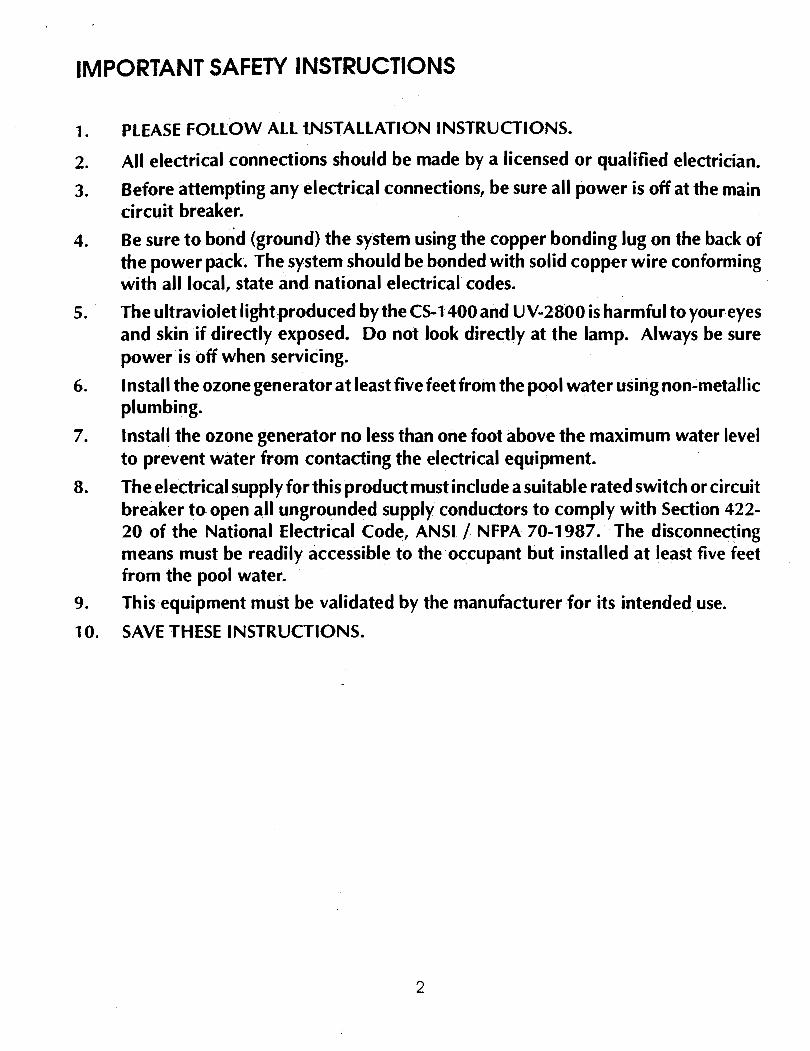
IMPORTANT SAFETY INSTRUCTIONS
1 PLEASE FOLLOW ALL iNSTALLATION INSTRUCTIONS
2 All electrical connections should be made by a licensed or qualified electrician
3 Before attempting any electrical connections be sure all power is off at the main circuit breaker
4 Be sure to bond (ground) the system using the copper bonding lug on the back of the power pack The system should be bonded with solid copper wire conforming with all local state and national electrical codes
5 The ultraviolet lightproduced by the CS-1400 and UV-2800 is harmfu I to your eyes and skin if directly exposed Do not look directly at the lamp Always be sure power is off when servicing
6 Install the ozone generator at least five feet from the pool wa-ter using non-metallic plumbing
7 Install the ozone generator no less than one foot above the maximum water level to prevent water from contacting the electrical equipment
8 The electrical supply for this product must include a suitable rated switch or circuit breaker to open all ungrounded supply conductors to comply with Section 422shy20 of the National Electrical Code ANSI I NFPA 70-1987 The disconnecting means must be readily accessible to the occupant but installed at least five feet from the pool water
9 This equipment must be validated by the manufacturer for its intended use
10 SAVE THESE INSTRUCTIONS
2
INSTALLING THE INJECTOR 1 Cut into the return line AFTER the pump filter and heater 2 Glue in the proper sized injector noting the proper direction of flow (notice the arrow on the injector) Most pools use
a single-speed pump requiring a siogle-speed injector If the pool has a two-speed pump use a two-speed injector If a single-speed injector is used the airflow will have to be adjusted for proper suction using an SCFH gauge (See below)
3 Once the injector is installed choose a location to mount the ozone generator as close to the injector as possible
USING AN SCFH GAUGE (Must be ordered separately) An SCFH (Standard Cubic Feet per Hour) gauge is used to accurately measure the amount of air flowing through the ozone delivery line This affects the amount of ozone being injected into the water
1 Install the tube fitting into the upper hole on the back side of the SCFH gauge
2 With the pump running (low speed on a two-speed system) disconnect the tubing from the ozone outlet of the ozone generator and connect the tubiAg to the fitting on the gauge
3 While holding the gauge vertically read the amount indicated on the gauge The optimum flow is 10 to 20 SCFH (1 0 is ideal) NOTE Do not obstruct the bottom air hole on the gauge
4 On a single speed pump system the injector will have a ball valvetoadjusttheamountofflow To adjusttheSCFH simply install the gauge as described above and open the ball valve completely With the pump running begin closing the ball valve until optimum flow is achieved on the SCFH gauge If possible remove the ball valve handle to prevent tampering
Attach Ozone
Une
KEEP GAUGE VERTICAL
Injector Manifold with Check Valve
MOUNTING Pick a location as close to the injector as possible to mountthe ozone generator While the CS-1400 and UV-2800 enclosures are rain tight it is best to pick a location out of the sun and rain
On the back I top side of the enclosure are mounting holes the unit can be attached to a wall using these mounting holes
3
CLEARWATER TECH MODEL CS-1400
Ozone Ou11et
~-- 250 Dia Ozone Reaction Chcrnber
Ozone Operation Light
~f---- Power Cord
4
CLEARWATER TECH MODEL UV-2800 r-- 850 -t ~---~
---- Ozcne Operation Lights (2)
(
Cooling FanOutet
Bonding Lug
_----Power Cord
Check Valve Ozone-Out Fitting
Cooling Fan Inlet
5
CLEARWATER TECH MODEL UV-2800 Internal Components
Ozone Indicator Lights (2)
IL_Il--lt--lft---- Reaction Chambers (2)
Lamp Holder Locking Rings (2)
Access Port for Optional OAS-20 Connection
Ozone Check Valve
Ozone Outlet
----- Ballast(s) (1 for 120V 2 for 240V)
Barrier Strip
Plugs (2)
Fan
Door Interlock
r-PowerCord
6
ELECTRICAL WIRING The objed is to have the ozone generator come on whenever the pool pump comes on for filtration The installation should lgte done by a licensed electrician All local codes must be observed
There are several ways to wire the CS-1400-and UV-2800 1 To a timer 2 Diredly to the eledrical panel 3 To the low speed connedion in the control box (on two-speed systems)
The CS-1400 and UV-2800 are available in 120 vohs and 240 volts Be sure to install the proper system for your pool application Before attempting any electrical hook-up be sure the power is OFF at the main circuit box
To hard wire a 11 OV system Run the black wire to position 1 2 or3listed above Run the neutral wire to a neutral terminal (proteded by a GFCI) Then run the ground to a ground terminal To hard wire a 220V system Run one black wire to position L 1 and run the second black wire to L2 Run the green wire to ground
BONDING REQUIREMENTS You must install a ground lead from the bonding lug (on the bottom left of the unit) to the pools exterior ground line This bonding wire should conform to all local state and national electrical codes (The standard recommendation is a 8 AWG copper wire)
SUPPLY TUBING CONNECTION Conned the supply tubing provided to the injedor Secure with the hose clamp provided
Inside the parts bag you will find a black 14 mpt x 38 barb hose connector Screw this into the ozone outlet (which has a built-in Kyna-reg check valve) located on the bottom of the ozone generator (to the left of the fan)
Connect the supply tubing from the injector to the black hose connector
NOTE This ozone generator is proteded by two check valves There is one cheeurok valve located at the injector and one check alve at the ozone generator outlet
INSTALLATION SCHEMATIC
C$-1400 or UV-2800
FILTER OZONE GENERATOR
t FLAPPER VALVE
---+ WATER
CHECK-VALVE
INJECTOR OZONE MANIFOLD with OUTLET CHECK VALVE OZONE
7
OPERATION After the installation has been completed the pool will operate as before The ozone system will go on and off automatically if controlled by a time clock The indicator lights (one on the CS-1400 two on the UV-2800) will be on if the unit is working and you should smell a slight odor of oz~ne from the water
Running Time It should not be necessary to increase your filtration time from the builders recommendation For pools the typical running time will vary greatly We recommend that you begin with two three-hour intervals daily However the bather load and frequency of use will vary from owner to owner Therefore you can adjust the time to fit your own needs by increasing or decreasing the hours on the time clock Again please refer to your builders recommendations Note On commercial systems the filtration time ~ill need to be increased
Understanding Your Water If you are aware of a high concentration of any mineral (like calcium or iron) in your water it is necessary to treat the water before starting the ozone system We suggest that you take a sample of your water to a qualified ClearWater Tech dealerfor analysis They will make the proper recommendations of product(s) needed to remove these minerals from the water You should only have to do this when y~u drain and fill new water into the pool
If your water is clean and clear you can start the ozone system right away If the water is dirty and cloudy we recommend that you first drain the water and thoroughly clean the filters (spas only) Caution It is not recommended that you drain a pool in the winter or after the first rain of the season Instead you should use a shock treatment because draining could possibly float the pool out of the ground resulting in severe damage
Ozone and Bromine Ozone has a short half-life or residual time in your water Therefore there is a need to maintain a small residual of another product in the pool We recommend the use of bromine This bromine residual will act as a buffer when the ozone system is not operating Bromine needs to be maintained between 1 to 15 ppm (parts per million) so that the trace amount of product in the water will not be noticed
Ozone and Chlorine For outdoor pools we recommend the use of chlorine to supplement the ozone This chlorine residual will act as a buffer when the ozone system is not operating To decide which form of chlorin~ to use in your pool refer to the chart on the following page
Prepare Your Water You should prepare your water by making the following adjustments and maintain these levels while using the ozone system
Chlorine 05 to 2 ppm or
Bromine 1 to 3 ppm pH 72 - 76 Total Alkalinity 80-150 ppm Calcium Hardness 180-250 ppm
Note If you experience any reaction with your water such as coloring or unusual odor please wait a few days to give the ozone and filter system time to work If the situation continues consult your pool dealer possibly taking them a sample of the water
Algae Always maintain a chlorine residual of at least 05 ppm (or a bromine residual of at least 1 ppm) in your pool water Brushing the sides of the pool once a week is also recommended
Shock Treatment lfthe water becomes cloudy with excessive oils or other contaminants or due to an unusually high bather load we recommend that you use a shock treatment to assist the ozone in cleaning the water These shock treatments are available at your local pool or spa supply dealer and are marketed under several different brand names Ask for assistance in selecting the proper product shy
8
Chlorine Types and Applications 0o Of
Type of Bromine Stabilizer Neutralizer FastAvailable pH Comments
or Chlorine Required Required DissolvingOxidizer
- Yes Works well in floaters
BROMINE 61 74 No (Muriatic No or feeders - Can be Acid or C02) used in vinyl pools
VeryGAS CHLORINE 100 Yes Yes Yes Dangerous
Acidic
Does notLIQUID CHLORINE have to- Can be used to (SODIUM 12 13 Yes Yes
Makes HoCI superchlorinateHYPOCHLORITE) instantly
middot No- Must be Extreme oxidizer-Yes
CALCIUM predissolved Do NOT use in a65 118 Yes (Muriatic
HYPOCHLORITE or broadcast vinyl pool - Can be Acid)
can cloud used in a feeder
Yes-No Can be used toSODIUM DICHLOR 56 68- 70 No Wi II not cloud(Built-in) superchlorinate
water
Works well in floaters -No Yes No-
TRICHLOR 90dego 28-30 Cannot be used to (Built-in) (Soda Ash) Very slow superchlorinate
Yes Cannot be used in aLITHIUM Yesshy35dego 107 Yes (Muriatic feeder - Can be usedHYPOCHLORITE Will not cloudAcid) in vinyl-lined pools
MAINTENANCE FiHer Care Ozone will keep your pool or spa much cleaner than any other type of water purification system~ This is because ozone neutralizes body oils and soaps After ozone kills the bacteria the by-produds are oxygen carbon dioxide and filterable solids Filterable solids are usually at a higher level than with conventional sterilization processes so your filter will have a bit more work to do Keep~ng the filter clean will make a noticeable difference in the clarity of the water Set up a regular filter cleaning program or the end result will be poor flow through the filter This will direoly affed the amount of ozone that gets into the water When starting your pool with the CS-1400 or UV-2800 you should clean your fi Iter once a week for the first month
The Ozone Lamp(s) Caution Never look atthe unshielded ozone lamp while operating the unit This lamp can cause severe eye and skin damage There is an indicator light which will tum blue in color when the unit is operating The CS-1400UV-2 800 lamps each have a 9000 hour life expectancy or about four years On commercial installations we recommend replacing the lamps every 1 2 to 1 8 months
9
MAINTENANCE (continued) Replacing the CS-1400 Lamp Lamps are available from your ClearWater Tech distributor should replacement be needed Simply turn off the power remove the two screws on the power pack cover _and remove the cover Disconnect the plug on the end of the ozone lamp Now loosen the lamp holder locking ring from around end of lamp by turning it counterclockwise and remove it Remove lamp by grabbing the rubber bushing around the end of the lamp and pulling it straight out Remove the rubber bushing from the lamp and install it on your new lamp making sure the outer edge of the bushing is flush with the outer edge of the silver end cap on the lamp Now slide the lamp back into the reaction chamber IMPORTANT There is a centering device inside at the other endof the chamber Care must be taken to make sure the lamp is inserted into the hole in the centering device before the lamp holder is tightened The lamp holder may now be reinstalled and tightened Reinstall the plug onto the lamp and replace the power pack cover Caution Keep lamp free of fingerprints and dust particles by only handling the metal end caps on the lamp You can clean the lamp with rubbing alcohol and a soft cloth A dirty lamp will not allow maximum ozone output
Replacing the UV-2800 Lamps Lamps are available from your ClearWater Tech dealer should replacement be needed Simply turn off the power remove the six screws on the power pack cover and remove the cover Disconnect the plug on the end of the ozone lamp(s) to be replaced Loosen the lamp holder locking ring from around the end of lamp Remove the lamp bygrasping the rubber bushing around the end of the lamp and pulling it straight out Remove the rubber bushing from the lamp and install it on your new I amp making sure the outer edge of the bushing is flush with the outer edge of the end cap on the lamp 51 ide the lamp back into the reaction chamber IMPORTANT There is a centering device inside at the other end ofthe chamber Care must be taken to make sure the lamp is inserted into the hole in the centering device before the lamp holder is tightened The lamp holder may now be reinstalled and tightened Reinstall the plug onto the lamp and replace the power pack cover Caution Keep lamp free of fingerprints and dust particles by handling only the metal end caps on the lamp A dirty lamp will not allow maximum ozone output You can clean the lamp with rubbing alcohol and a soft cloth
TROUBLESHOOTING
PROBLEMSYMPTOM POSSIBLE CAUSE SOLUTION
Unit does not turn on No power to unit Check breakers
Switch not turned on Check switch
Blown fuse Replace fuse
Coverdoor interlock not active Check door interlock switch (UV-2800 only) replace cover
Unit does not stay on Unit overheating Clean fan filter check fan (UV-2800 only)
Only one ozone chamber lights Bad lamp or ballast Switch ballast connections between (UV-2800 only) chambers - if opposite chamber I ights
replace ballast if same one lights replace lamp
Water in unit or Inadequate vacuum Adjust injector vacuum ozone delivery tubing Defective check valve(s) Replace check valve(s)
Excessive back pressure on check valve Back pressure not to exceed 40 psi -if over 40 psi consult ClearWater Tech dealer middot
Ozone smell present Insufficient vacuum Adjust injector vacuum
Loose internal fittings Inspect and tighten fittings
Defective ozone chamber Replace chamber
10
CS-1400 amp UV-2800 REPLACEMENT PARTS QUANTITY REQUIRED PART DESCRIPTION CS-1400 UV-2800
LA25 Ozone Lamp(s) 1 2 CKV20 Kynar4D Check Valves 2 2 FA20 Cooling Fan Filter Element NA 1 Bl30 Ballast thermally protected self-starting 120VAC 5060 Hz 1 1 BL60 Ballast thermally protected self-starting 240VAC 60Hz 1 1
CS-1400 SPECIFICATIONS ENERGY REQUIRED 120V 1 05VAC MIN 125VAC MAX 60HZ 08 AMP POWER CONSUMPTION 96 WATTS RATED FOR MEDIUM RESIDENTIAL POOLS AND COMMERCIAL SPAS AVERAGE LAMP LIFE ~ 9000 HOURS LAMP WAVELENGTH 185 nm DIMENSIONS 3125L X 75W X 425D SHIPPING WEIGHT 15 LBS
UV-2800 SPECIFICATIONS ENERGY REQUIRED UV-2800 120V 1 05VAC MIN 125VAC MAX 60HZ 16 AMP ENERGY REQUIRED UV-2800 240V 210VAC MIN 245V MAX 60HZ 08 AMP POWER CONSUMPTION 192 WATIS RATED FOR LARGE RE~IDENTIAL POOLS AND COMMERCIAL SPAS AVERAGE LAMP LIFE 9000 HOURS LAMP WAVELENGTH 185 nm DIMENSIONS 32L X BSW X 35D
SHIPPING WEIGHT 25 LBS
ll
MANUFACTURERS FIVE YEAR LIMITED WARRANTY
ClearWater Tech Inc warrants that all electrical components of the ClearWater Tech ultraviolet ozone generator will be free from defects in materials and workmanship for a period of one (1) year from the date the unit is purchased by the end user The check valves provided with the ozone generator shall carry the same one year warranty ClearWater Tech further warrants that all other non-electrical components of the ozone generator wi II be free from defects in materials and workmanship for a period of five years from date of purchase by the end user Should any component malfunction due to defects in materials or workmanship during the warranty period ClearWater Tech will repair or replace it at no charge The option to repair or replace the component(s) shall remain at the sole discretion of ClearWater Tech Inc
ClearWater Tech Inc shall not be responsible for loss of use of the ozone generator or other consequential or incidental damages expenses or costs related to such loss Any unit found to be defective during the stated warranty period may be returned to the authorized dealer from which it was originally purchased or directly to the ClearWater Tech factory If it becomes necessary to return the ozone generator to the ClearWater Tech factory during the warranty period the owner shall be responsible for shipping the unit freight prepaid Upon completion ofthe required warranty work ClearWater Tech Inc shall return the ozone generator to the owner freight prepaid Prior to shipment a Returned Goods Authorization (RGA) number must be obtained by calling the ClearWater Tech factory The RGA number must be clearly written on the outside ofthe shipping box(es) When calling have the model and serial numbers available
This warranty is in lieu of all other warranties either expressed or implied including but not limited to implied warranties of merchantability or fitness for a particular purpose In no event shall ClearWater Tech Inc be liable for an amount in excess of the original purchase price of the ozone generator
No agent dealer distributor or service company is authorized to change modify or extend the terms of this warranty in any manner whatsoever This warranty gives you specific legal rights You may also have other rights which may vary from state to state This warranty is valid only in the fifty states of the United States of America
This warranty does not cover any ClearWater Tech ozone generator which has been damaged due to misuse abuse neglect mishandling flood fire or causes beyond the control of ClearWater Tech Furthermore this warranty does not cover damage caused by the use ofparts found to be incompatible with the proper functioning of the ozone generator and does not extend to any unit that has been altered or modified This warranty is not transferable to any subsequent owner and is valid only so long as the ozone generator is installed and operated in accordance with the owners manual Under the conditions outlined in this paragraph ClearWater Tech Inc assumes no responsibility for labor costs or service charges involved in the removal or replacement of the defective part(s) of the zone generator
For prompt warranty service make sure the warranty card is returned to ClearWater Tech Inc within ten (1 O) days of purchase Failure to complete and return the warranty card will void this warranty
Please accept our sincere thanks for choosing a ClearWater Tech ozone generator
ClearWater Tech Inc PO Box 15330
San Luis Obispo CA 93406 (805) 549-9724
12
~~Settmg the tandOKf to effbulloencv
mazzei injector corporation
Air Injection Assemblies
- ~_nomated Air amp Ozone Injection System --------------
~ r= iv1azzeiAutornated Air amp Ozone injection smiddotS2rrgt features a high efficiency Mazzei injector ~7-licd in o bypass assembly with an adjustable ~_ ~ oaded fiow control valve The adjustable ~Oi~- is capable of creating pressure differentials frcrr 10 to as high as 20 psi with minimal flow rsstrictions This permits the combination to optimize suction while minimizing restrictions from -3i Jump to pressurized tank The injectors are r_ded of ozone resistant PVDF (KYNAR) and the yJass assembly features schedule 80 PVC fittings for added durability and strength Pressure difrerentials can easily be adjusted to match the ~ iication without unit removal Union fittings -2r~ it injectors to be removed for servicing or replacement
---middot- ----------------------------------------
__ ~~--Jnlatic Air Volume Control For Pressurized Water Storage Tanks-----
Th0 rv1azzei Automatic Air Volume Control features a high efficiehcy Mazzei injector installed in a bypass assembly with an adjustable i=)ring loaded flow control valve and a float air volume control installed in the tank A tube connects the injector suction to the float air vourne control valve The float air volume cnnoi opens as the water level in the tank rises anci air is permitted to be sucked into the water stream through the injector The aerated water recr1arges the depleted air and prevents water logging of the pressure tank The assembly tsmures an injector molded of PVDF (KYNAR) and _c gteGJie 80 PVC fittings for added strength The gt-ure differential is achieved by an adjustable fi-middot control valve allowing it to be matched to ~-~middot= -sui~ernents of the pressure system Union ~~are used to permit removing the injectors fo servicing or replacement
cJ Rooster Dnve bull Bakersfield California 93307 USA bull Phone (805) 363-6500 bull FAX (8fJ5) 363-7500
ozone system INSTALLATION AND OWNERS MANUAL
ultraviolet
PR-1300 ozone generator PO BOX 15330 SAN LUIS OBISPO CA 93406
Copyrightcopy 1993 -ClearWater Tech Inc bull Reproduction of any kind IS prohibited bull Rev 1293
IMPORTANT SAFETY INSTRUCTIONS
1 PLEASE FOLLOW All-INSTALLATION INSTRUCTIONS
2 Before attempting any electrical connections be sure all power is off at the main circuit breaker
3 The ultraviolet light produced by the PR-1300 is harmful to your eyes and skin if directly exposed Do not look directly at the lamp Always be sure power is off when servicing
4 Install the ozone generator at least five feet from the tub water using non-metallic plumbing
5 Install the ozone generator no less than one foot above the maximum water level to prevent water from contacting the electrical equipment
6 The electrical supply for this product must include a suitable rated switch or circuit breaker to open all ungrounded supply conductors to comply with Section 422shy20 of the National Electrical Code ANSI I NFPA 70-1987 The disconnecting means must be readily accessible to the occupant but installed at least five feet from the tub water
7 This equipment must be validated by the manufacturer for its intended use
8 SAVE THESE INSTRUCTIONS
2
PRODUCT DESCRIPTION We recommend that you become familiar with the PR-1300 unit by studying this illustration All components will be referred to by the names below
Power Supply to UV Lamp -----
UV Lamp Holder---T__JJLL------
Indicator Light --f-=-tt-t~middot
Reaction Chamber-----~to~ Mounting
Brackets
0
___--+---- 24 Hour Timer
Ozone Outlet Connector-----~~
____ Grounded Electrical Cord
Grounding Lug-----
3
PLUMBING There are three ways to plumb the PR-1300
1 Using a tee in the air venturi line 2 Using a diffuser stone 3 Using a saddle clamp in the air venturi line
NOTE All fittings with the exception of a tee will be provided by ClearWater Tech
AIR LINE TEE INSTALLATION NOTE Use the following instructions if the venturi or air line of the spa is accessible The air line is the upper PVC pipe flex or rigid of the jet fittings If the venturi line is not accessible the instructions for the diffuser stone should be followed
For air line tee installation locations see the installation schematic T1 amp T2
1 Mount the PR-1300 using the four mounting brackets The system is intended to be mounted five feet from the spa or at the remote power pack site
2 Determine the size of the venturi line either 12 34 or 1 12 Purchase a PVC tee the same size as your line with a 12 female threaded top
3 Turn the spa on high speed (blower not necessary) By having the spa on water will evacuate this line If your seleaed plumbing location is in an area over the power pack we recommend draining the spa
4 Cut the PVC pipe between the two lowest jets (if possible) this will give you the longest contaa time If the low jets are not accessible any location on this line will work
5 Cement the tee in place with the 12 threads opening up
6 Using teflon tape screw the provided tube fitting into 1 2 threads in the tee Install one end of the ozone delivery line on the tube fitting
7 Run the delivery line up from the tee to the highest point possible and cut the line here to install the check valve (See illustrations on installation schematic) NOTE THE CHECK VALVE SHOULD BE MOUNTED ABOVE THE WATER LINE BE SURE THE FREE FLOW IS TOWARDS THE ELBOW OR AWAY FROM THE OZONE UNIT
8 Continue running the delivery line back down and out to the ozone generator
4
DIFFUSER STONE APPLICATION 1 The diffuser stone is already connected to the end of the ozone tubing supplied by ClearWater Tech
2 Simply attach the open end of the tubing to the fitting at the bottom of the PR-1300 and drop the diffuser stone into the spa When the ozonatomiddotr_is operating you should see tiny bubbles being dispersed from the diffuser stone
NOTE FOR OPTIMAL RESULTS USE THE DIFFUSER STONE SIMULTANEOUSLY WITH THE FILTRATION CYCLE
NOTE DIFFUSER STONES MAY BECOME CLOGGED AND RESULT IN AIR COMPRESSOR DAMAGE TO PREVENT THIS FROM HAPPENING IT IS RECOMMENDED TO CLEAN YOUR DIFFUSER STONE ONCE A MONTH THIS CAN BE DONE BY SUBMERSING THE DIFFUSER STONE FOR A FEW HOURS IN A SOLUTION MADE OF 50 WATER AND 50 MURIATIC ACID
INSTALLATION SCHEMATIC
Air Control Valve (Must remain closed on air line installations)
Check Valve mounted ABOVE the water level
Location SC 2
Ozone Delivery Line
5
SADDLE CLAMP INSTALLATION 1 Find a SLitable location for the saddle clamp See the installation schematic locations SCl amp SC2 for examples
2 Turn on the spa to low speed~ (filter mode)
3 Drill a 516 hole Note A spade bit is best but a twist bit will also work
4 Install the saddle clamp as shown in illustration below
5 Run the delivery line to the highest accessible location Splice the line here and insert the check valve (noting tlow diredion) Continue running delivery line to the ozone generator
ORing gasket
516 Drilled Hole
Saddle Clamp
Ozone Delivery Line
Hose Clamp
Spa Air Une
6
ELECTRICAL WIRING Models with cords simply need to be plugged into a grounded 11 OV wall outlet An overcurrent protedor must be provided by conneding to a branch circuit rated at 20 AMPS or less NOTE ALL LOCAL ELECTRICAL CODES MUST BE OBSERVED
GFI (GROUND FAULT INTERRUPTER) 1 To test the GFI push the black TEST button Red RESET button should pop out from inner surface This should result
in power being OFF at all outlets proteaed by the GFI NOTE If RESET button does not pop out DO NOT USE THIS ELECTRICAL APPLIANCE CALL A QUALIFIED ELECTRICIAN
2 If the GFI tests okay restore power by pushing the RESET button in The RESET button must be pushed firmly and fully into place until it locks and remains depressed after pressure has been removed IF THE GFI FAILS TO RESET PROPERLY DO NOT USE- CALL A QUALIFIED ELECTRICIAN
3 If GFI trips by itself at any time during or after installation RESET it and perform test procedures 1 and 2 above IF RESET BUTION DOES NOT POP OUT WHEN TEST BUTION IS DEPRESSED DO NOT USE GFI CALL A QUALIFIED ELECTRICIAN NOTE THE GFI SHOULD BE TESTED AT LEAST ONCE A MONTH
OPERATION After the installation has been completed the spa will operate as before Again for best results run the timer of your PR-1300 simultaneously with the filtration cycle
NOTE If your PR-1300 is installed to your air line it is important to remember to keep the air dial(s) closed when not using the spa
The indicator light on the PR-1300 will be on if the unit is working and you should smell a slight odor of ozone from the spa
RUNNING TIME We suggest you start out with 4 hours of total running time It is best to split this time up into at least two two-hour intervals or four one-hour intervals We recommend you start with the longer periods and work your way down until you find the optimum running time for your application
Examples 10-12 AM or 12-1 AM and 12-1 PM 10-12 PM or 6-7 AM and 6-7 PM
The bather load and frequency of use wi II differ from owner to owner therefore you can adjust the time to fit your own needs by increasing or decreasing the hours on your time clock NOTE On commercial systems the filtration time will need to be increased Please consult your dealer
7
UNDERSTANDING YOUR WATER If you are aware of a high concentration of any mineral in your water (like calcium or iron) it is necessary to treat your water before starting the PR-1300 system We suggest you take a sample of your water to a qualified pool and spa dealer for analysis They will make the proper recommendations of produd(s) needed to remove these minerals from your water You should only have to do this when you drain and fill new water into the spa
If your water is clean and clear you can start the PR-1300 system right away If the water is dirty or cloudy we recommend that you drain the water and thoroughly clean the filter(s) first
CAUTION It is not recommended that you drain an in-ground spa in the winter or after the first rain of the season Instead you should use a shock treatment because by draining you could possibly tloat the spa out of the ground resulting in severe damage
OZONE AND BROMINE Ozone has a short half-life or residual time in your water So there is a need to maintain a small residual of another produd iri the spa or pool We recommend that you use Bromine This Bromine residual will ad as a buffer when the ozone system is not operating The bromine needs to be maintained at ONLY 8 ppm (parts per mill ion) so that the trace amount of produd in the water will not be noticed Chlorine will work as a residual oxidizer and may be used effedively in conjundion with the ozone system
Prepare your Water You should prepare your water by making the following adjustments and maintain these levels while using the PR-1300 system
Bromine 1 to 8 ppm or
Chlorine pH Total Alkalinity Calcium Hardness
1 to 5 ppm 72-76
80-150 ppm 180-250
Note If you experience any reaction with your water such as coloring or unusual odor please wait a few days to give the ozone and filter system time to work If the situation continues consult your pool and spa dealer possibly taking them a sample of the water
SHOCK TREATMENT If the water becomes cloudy with excessive oils or other contaminates or after an unusually high bather load we recommend that you use a Non-chlorine shock treatment to assist the ozone in cleaning the water These Non-chlorine shock treatments are available at your local pool or spa supply dealer and are marketed under several different brand names ask for assistance in selecting the proper product
FILTER CLEANING Ozone will keep your spa much cleaner than any other type of spa or pool purification system The reason is that ozone neutralizes body oils and soaps After ozone kills the bacteria the end product is oxygen carbon dioxide and filterable solids The filterable solids are usually at a higher level than with conventional sterilization processes so your filter has a bit more work to do Keeping the filter clean will make a definite difference in the clarity of the water Please set up a regular cleaning program or the end result will be poor flow when the low speed of the pump comes on with the ozone system This will have a direct effect on the amount of ozone that will get into the water An easy check you can do without removing the filter is to look for air bubbles through the jets (on air line installations) when the spa system is on low speed (usually controlled by the timer) When the filter is clean you will see many bubbles when it is dirty you will hardly see any bubbles
8
TROUBLE SHOOTING SITUATION No indicator light 1 Check GFI to see if it has tripped 2 Check lamp connedion 3 Check for blown lamp 4 Check power supply
SITUATION Ozone not present in water 1 Check for clean filter (a dirty filter will cause a low flow of ozone to spal 2 Make sure air dial is closed on air line installations 3 Make sure adjustable jets are all open and not loose 4 Check for clogged jet (debris in line) 5 Check for kinked delivery line blocked or reversed check valve 6 Check diffuser stone to see that it has not been fowled
SITUATION Cloudy water with ozone present 1 Check pH balance 2 Clean filter 3 Check for other minerals in water 4 Use a spa shock treatment to rid water of excess body oils 5 Drain and clean spa and filter thoroughly
PR-1300 SPECIFICATIONS Energy required 115 VAC 06 AMPS 65 watts Rated up to 1000 gallon spa or 2000 gallon pool Average lamp life 8500 hours Compressor rating 6 PSI Size 20 x 8 34 x 3 1 2 Shipping Weight 20 lbs
9
MANUFACTURERS FIVE YEAR LIMITED WARRANTY
ClearWater Tech Inc warrants that all electrical components of the ClearWater Tech ozone generator wi II be free from defects in materials and workmanship for a period of one (1) year from the date the unit is purchased by the end user The check valves provided with the ozone generator shall carry the same one year warranty ClearWater Tech further warrants that all other non-electrical components will be free from defects and workmanship for a period of five years from date of purchase by the end user Should any component malfunction due to defects in materials or workmanship during the warranty period ClearWater Tech will repair or replace it at no charge The option to repair or replace the component(s) shall remain at the sole discretion of ClearWater Tech Inc
ClearWater Tech Inc shall not be responsible for loss of use of the ozone generator or other consequential or incidental damages expenses or costs related to such loss Any unit found to be defective during the stated warranty period may be returned to the authorized dealer from which it was originally purchased or directly to the ClearWater Tech factory If it becomes necessary to return the ozone generator to the ClearWater Tech factory the owner shall be responsible for shipping the unit freight prepaid Upon completion of the required warranty work ClearWater Tech Inc shall return the ozone generator to the owner freight prepaid Prior to shipment a Returned Goods Authorization (RGA number must be obtained by calling the ClearWater Tech factory The number must be clearly written on the shipping box(es When calling have the model and serial numbers available
This warranty is in lieu of all other warranties either expressed or implied including but not limited to implied warranties of merchantability or fitness for a particular purpose In no event shall ClearWater Tech Inc be liable for an amount in excess of the original purchase price of the ozone generator
No agent dealer distributor or service company is authorized to change modify or extend the terms of this warranty in any manner whatsoever This warranty gives you specific legal rights You may also have other rights which may vary from state to state This warranty is valid only in the fifty states of the United States of America
This warranty does not cover any ClearWater Tech ozone generator which has been damaged due to misuse abuse neglect mishandling flood fire or causes beyond the control of ClearWater Tech Furthermore this warranty does not cover damage caused by the use of parts found to be incompatible with the proper functioning of the ozone generator and does not extend to any unit that has been altered or modified This warranty is not transferable to any subsequent owner and is valid only so long as the ozone generator is installed and operated in accordance with the owners manual Under the conditions outlined in this paragraph ClearWater Tech Inc assumes no responsibility for labor costs or service charges involved in the removal or replacement of the defective part(s) of the ozone generator
For prompt warranty service make sure the attached warranty card is returned to ClearWater Tech Inc within ten (1 0) days of purchase Failure to complete and return the warranty card will void this warranty
Please accept our sincere thanks for choosing a ClearWater Tech ozone generator
ClearWater Tech Inc PO Box 15330
San Luis Obispo CA 93406 (805) 549-9724
10

t EC RC u_ L1I 0 l ozone system INSTALLATION AND OWNERS MANUAL
ultraviolet
CS-1400 amp UV-2800middot qzone generator PO BOX 15330 SAN LUIS OBISPO CA 93406
QI
Copyright CO 1993 - ClearWater Tech Inc bull Reproduction of any kind is prohibited bull Rev 0596
1
IMPORTANT SAFETY INSTRUCTIONS
1 PLEASE FOLLOW ALL iNSTALLATION INSTRUCTIONS
2 All electrical connections should be made by a licensed or qualified electrician
3 Before attempting any electrical connections be sure all power is off at the main circuit breaker
4 Be sure to bond (ground) the system using the copper bonding lug on the back of the power pack The system should be bonded with solid copper wire conforming with all local state and national electrical codes
5 The ultraviolet lightproduced by the CS-1400 and UV-2800 is harmfu I to your eyes and skin if directly exposed Do not look directly at the lamp Always be sure power is off when servicing
6 Install the ozone generator at least five feet from the pool wa-ter using non-metallic plumbing
7 Install the ozone generator no less than one foot above the maximum water level to prevent water from contacting the electrical equipment
8 The electrical supply for this product must include a suitable rated switch or circuit breaker to open all ungrounded supply conductors to comply with Section 422shy20 of the National Electrical Code ANSI I NFPA 70-1987 The disconnecting means must be readily accessible to the occupant but installed at least five feet from the pool water
9 This equipment must be validated by the manufacturer for its intended use
10 SAVE THESE INSTRUCTIONS
2
INSTALLING THE INJECTOR 1 Cut into the return line AFTER the pump filter and heater 2 Glue in the proper sized injector noting the proper direction of flow (notice the arrow on the injector) Most pools use
a single-speed pump requiring a siogle-speed injector If the pool has a two-speed pump use a two-speed injector If a single-speed injector is used the airflow will have to be adjusted for proper suction using an SCFH gauge (See below)
3 Once the injector is installed choose a location to mount the ozone generator as close to the injector as possible
USING AN SCFH GAUGE (Must be ordered separately) An SCFH (Standard Cubic Feet per Hour) gauge is used to accurately measure the amount of air flowing through the ozone delivery line This affects the amount of ozone being injected into the water
1 Install the tube fitting into the upper hole on the back side of the SCFH gauge
2 With the pump running (low speed on a two-speed system) disconnect the tubing from the ozone outlet of the ozone generator and connect the tubiAg to the fitting on the gauge
3 While holding the gauge vertically read the amount indicated on the gauge The optimum flow is 10 to 20 SCFH (1 0 is ideal) NOTE Do not obstruct the bottom air hole on the gauge
4 On a single speed pump system the injector will have a ball valvetoadjusttheamountofflow To adjusttheSCFH simply install the gauge as described above and open the ball valve completely With the pump running begin closing the ball valve until optimum flow is achieved on the SCFH gauge If possible remove the ball valve handle to prevent tampering
Attach Ozone
Une
KEEP GAUGE VERTICAL
Injector Manifold with Check Valve
MOUNTING Pick a location as close to the injector as possible to mountthe ozone generator While the CS-1400 and UV-2800 enclosures are rain tight it is best to pick a location out of the sun and rain
On the back I top side of the enclosure are mounting holes the unit can be attached to a wall using these mounting holes
3
CLEARWATER TECH MODEL CS-1400
Ozone Ou11et
~-- 250 Dia Ozone Reaction Chcrnber
Ozone Operation Light
~f---- Power Cord
4
CLEARWATER TECH MODEL UV-2800 r-- 850 -t ~---~
---- Ozcne Operation Lights (2)
(
Cooling FanOutet
Bonding Lug
_----Power Cord
Check Valve Ozone-Out Fitting
Cooling Fan Inlet
5
CLEARWATER TECH MODEL UV-2800 Internal Components
Ozone Indicator Lights (2)
IL_Il--lt--lft---- Reaction Chambers (2)
Lamp Holder Locking Rings (2)
Access Port for Optional OAS-20 Connection
Ozone Check Valve
Ozone Outlet
----- Ballast(s) (1 for 120V 2 for 240V)
Barrier Strip
Plugs (2)
Fan
Door Interlock
r-PowerCord
6
ELECTRICAL WIRING The objed is to have the ozone generator come on whenever the pool pump comes on for filtration The installation should lgte done by a licensed electrician All local codes must be observed
There are several ways to wire the CS-1400-and UV-2800 1 To a timer 2 Diredly to the eledrical panel 3 To the low speed connedion in the control box (on two-speed systems)
The CS-1400 and UV-2800 are available in 120 vohs and 240 volts Be sure to install the proper system for your pool application Before attempting any electrical hook-up be sure the power is OFF at the main circuit box
To hard wire a 11 OV system Run the black wire to position 1 2 or3listed above Run the neutral wire to a neutral terminal (proteded by a GFCI) Then run the ground to a ground terminal To hard wire a 220V system Run one black wire to position L 1 and run the second black wire to L2 Run the green wire to ground
BONDING REQUIREMENTS You must install a ground lead from the bonding lug (on the bottom left of the unit) to the pools exterior ground line This bonding wire should conform to all local state and national electrical codes (The standard recommendation is a 8 AWG copper wire)
SUPPLY TUBING CONNECTION Conned the supply tubing provided to the injedor Secure with the hose clamp provided
Inside the parts bag you will find a black 14 mpt x 38 barb hose connector Screw this into the ozone outlet (which has a built-in Kyna-reg check valve) located on the bottom of the ozone generator (to the left of the fan)
Connect the supply tubing from the injector to the black hose connector
NOTE This ozone generator is proteded by two check valves There is one cheeurok valve located at the injector and one check alve at the ozone generator outlet
INSTALLATION SCHEMATIC
C$-1400 or UV-2800
FILTER OZONE GENERATOR
t FLAPPER VALVE
---+ WATER
CHECK-VALVE
INJECTOR OZONE MANIFOLD with OUTLET CHECK VALVE OZONE
7
OPERATION After the installation has been completed the pool will operate as before The ozone system will go on and off automatically if controlled by a time clock The indicator lights (one on the CS-1400 two on the UV-2800) will be on if the unit is working and you should smell a slight odor of oz~ne from the water
Running Time It should not be necessary to increase your filtration time from the builders recommendation For pools the typical running time will vary greatly We recommend that you begin with two three-hour intervals daily However the bather load and frequency of use will vary from owner to owner Therefore you can adjust the time to fit your own needs by increasing or decreasing the hours on the time clock Again please refer to your builders recommendations Note On commercial systems the filtration time ~ill need to be increased
Understanding Your Water If you are aware of a high concentration of any mineral (like calcium or iron) in your water it is necessary to treat the water before starting the ozone system We suggest that you take a sample of your water to a qualified ClearWater Tech dealerfor analysis They will make the proper recommendations of product(s) needed to remove these minerals from the water You should only have to do this when y~u drain and fill new water into the pool
If your water is clean and clear you can start the ozone system right away If the water is dirty and cloudy we recommend that you first drain the water and thoroughly clean the filters (spas only) Caution It is not recommended that you drain a pool in the winter or after the first rain of the season Instead you should use a shock treatment because draining could possibly float the pool out of the ground resulting in severe damage
Ozone and Bromine Ozone has a short half-life or residual time in your water Therefore there is a need to maintain a small residual of another product in the pool We recommend the use of bromine This bromine residual will act as a buffer when the ozone system is not operating Bromine needs to be maintained between 1 to 15 ppm (parts per million) so that the trace amount of product in the water will not be noticed
Ozone and Chlorine For outdoor pools we recommend the use of chlorine to supplement the ozone This chlorine residual will act as a buffer when the ozone system is not operating To decide which form of chlorin~ to use in your pool refer to the chart on the following page
Prepare Your Water You should prepare your water by making the following adjustments and maintain these levels while using the ozone system
Chlorine 05 to 2 ppm or
Bromine 1 to 3 ppm pH 72 - 76 Total Alkalinity 80-150 ppm Calcium Hardness 180-250 ppm
Note If you experience any reaction with your water such as coloring or unusual odor please wait a few days to give the ozone and filter system time to work If the situation continues consult your pool dealer possibly taking them a sample of the water
Algae Always maintain a chlorine residual of at least 05 ppm (or a bromine residual of at least 1 ppm) in your pool water Brushing the sides of the pool once a week is also recommended
Shock Treatment lfthe water becomes cloudy with excessive oils or other contaminants or due to an unusually high bather load we recommend that you use a shock treatment to assist the ozone in cleaning the water These shock treatments are available at your local pool or spa supply dealer and are marketed under several different brand names Ask for assistance in selecting the proper product shy
8
Chlorine Types and Applications 0o Of
Type of Bromine Stabilizer Neutralizer FastAvailable pH Comments
or Chlorine Required Required DissolvingOxidizer
- Yes Works well in floaters
BROMINE 61 74 No (Muriatic No or feeders - Can be Acid or C02) used in vinyl pools
VeryGAS CHLORINE 100 Yes Yes Yes Dangerous
Acidic
Does notLIQUID CHLORINE have to- Can be used to (SODIUM 12 13 Yes Yes
Makes HoCI superchlorinateHYPOCHLORITE) instantly
middot No- Must be Extreme oxidizer-Yes
CALCIUM predissolved Do NOT use in a65 118 Yes (Muriatic
HYPOCHLORITE or broadcast vinyl pool - Can be Acid)
can cloud used in a feeder
Yes-No Can be used toSODIUM DICHLOR 56 68- 70 No Wi II not cloud(Built-in) superchlorinate
water
Works well in floaters -No Yes No-
TRICHLOR 90dego 28-30 Cannot be used to (Built-in) (Soda Ash) Very slow superchlorinate
Yes Cannot be used in aLITHIUM Yesshy35dego 107 Yes (Muriatic feeder - Can be usedHYPOCHLORITE Will not cloudAcid) in vinyl-lined pools
MAINTENANCE FiHer Care Ozone will keep your pool or spa much cleaner than any other type of water purification system~ This is because ozone neutralizes body oils and soaps After ozone kills the bacteria the by-produds are oxygen carbon dioxide and filterable solids Filterable solids are usually at a higher level than with conventional sterilization processes so your filter will have a bit more work to do Keep~ng the filter clean will make a noticeable difference in the clarity of the water Set up a regular filter cleaning program or the end result will be poor flow through the filter This will direoly affed the amount of ozone that gets into the water When starting your pool with the CS-1400 or UV-2800 you should clean your fi Iter once a week for the first month
The Ozone Lamp(s) Caution Never look atthe unshielded ozone lamp while operating the unit This lamp can cause severe eye and skin damage There is an indicator light which will tum blue in color when the unit is operating The CS-1400UV-2 800 lamps each have a 9000 hour life expectancy or about four years On commercial installations we recommend replacing the lamps every 1 2 to 1 8 months
9
MAINTENANCE (continued) Replacing the CS-1400 Lamp Lamps are available from your ClearWater Tech distributor should replacement be needed Simply turn off the power remove the two screws on the power pack cover _and remove the cover Disconnect the plug on the end of the ozone lamp Now loosen the lamp holder locking ring from around end of lamp by turning it counterclockwise and remove it Remove lamp by grabbing the rubber bushing around the end of the lamp and pulling it straight out Remove the rubber bushing from the lamp and install it on your new lamp making sure the outer edge of the bushing is flush with the outer edge of the silver end cap on the lamp Now slide the lamp back into the reaction chamber IMPORTANT There is a centering device inside at the other endof the chamber Care must be taken to make sure the lamp is inserted into the hole in the centering device before the lamp holder is tightened The lamp holder may now be reinstalled and tightened Reinstall the plug onto the lamp and replace the power pack cover Caution Keep lamp free of fingerprints and dust particles by only handling the metal end caps on the lamp You can clean the lamp with rubbing alcohol and a soft cloth A dirty lamp will not allow maximum ozone output
Replacing the UV-2800 Lamps Lamps are available from your ClearWater Tech dealer should replacement be needed Simply turn off the power remove the six screws on the power pack cover and remove the cover Disconnect the plug on the end of the ozone lamp(s) to be replaced Loosen the lamp holder locking ring from around the end of lamp Remove the lamp bygrasping the rubber bushing around the end of the lamp and pulling it straight out Remove the rubber bushing from the lamp and install it on your new I amp making sure the outer edge of the bushing is flush with the outer edge of the end cap on the lamp 51 ide the lamp back into the reaction chamber IMPORTANT There is a centering device inside at the other end ofthe chamber Care must be taken to make sure the lamp is inserted into the hole in the centering device before the lamp holder is tightened The lamp holder may now be reinstalled and tightened Reinstall the plug onto the lamp and replace the power pack cover Caution Keep lamp free of fingerprints and dust particles by handling only the metal end caps on the lamp A dirty lamp will not allow maximum ozone output You can clean the lamp with rubbing alcohol and a soft cloth
TROUBLESHOOTING
PROBLEMSYMPTOM POSSIBLE CAUSE SOLUTION
Unit does not turn on No power to unit Check breakers
Switch not turned on Check switch
Blown fuse Replace fuse
Coverdoor interlock not active Check door interlock switch (UV-2800 only) replace cover
Unit does not stay on Unit overheating Clean fan filter check fan (UV-2800 only)
Only one ozone chamber lights Bad lamp or ballast Switch ballast connections between (UV-2800 only) chambers - if opposite chamber I ights
replace ballast if same one lights replace lamp
Water in unit or Inadequate vacuum Adjust injector vacuum ozone delivery tubing Defective check valve(s) Replace check valve(s)
Excessive back pressure on check valve Back pressure not to exceed 40 psi -if over 40 psi consult ClearWater Tech dealer middot
Ozone smell present Insufficient vacuum Adjust injector vacuum
Loose internal fittings Inspect and tighten fittings
Defective ozone chamber Replace chamber
10
CS-1400 amp UV-2800 REPLACEMENT PARTS QUANTITY REQUIRED PART DESCRIPTION CS-1400 UV-2800
LA25 Ozone Lamp(s) 1 2 CKV20 Kynar4D Check Valves 2 2 FA20 Cooling Fan Filter Element NA 1 Bl30 Ballast thermally protected self-starting 120VAC 5060 Hz 1 1 BL60 Ballast thermally protected self-starting 240VAC 60Hz 1 1
CS-1400 SPECIFICATIONS ENERGY REQUIRED 120V 1 05VAC MIN 125VAC MAX 60HZ 08 AMP POWER CONSUMPTION 96 WATTS RATED FOR MEDIUM RESIDENTIAL POOLS AND COMMERCIAL SPAS AVERAGE LAMP LIFE ~ 9000 HOURS LAMP WAVELENGTH 185 nm DIMENSIONS 3125L X 75W X 425D SHIPPING WEIGHT 15 LBS
UV-2800 SPECIFICATIONS ENERGY REQUIRED UV-2800 120V 1 05VAC MIN 125VAC MAX 60HZ 16 AMP ENERGY REQUIRED UV-2800 240V 210VAC MIN 245V MAX 60HZ 08 AMP POWER CONSUMPTION 192 WATIS RATED FOR LARGE RE~IDENTIAL POOLS AND COMMERCIAL SPAS AVERAGE LAMP LIFE 9000 HOURS LAMP WAVELENGTH 185 nm DIMENSIONS 32L X BSW X 35D
SHIPPING WEIGHT 25 LBS
ll
MANUFACTURERS FIVE YEAR LIMITED WARRANTY
ClearWater Tech Inc warrants that all electrical components of the ClearWater Tech ultraviolet ozone generator will be free from defects in materials and workmanship for a period of one (1) year from the date the unit is purchased by the end user The check valves provided with the ozone generator shall carry the same one year warranty ClearWater Tech further warrants that all other non-electrical components of the ozone generator wi II be free from defects in materials and workmanship for a period of five years from date of purchase by the end user Should any component malfunction due to defects in materials or workmanship during the warranty period ClearWater Tech will repair or replace it at no charge The option to repair or replace the component(s) shall remain at the sole discretion of ClearWater Tech Inc
ClearWater Tech Inc shall not be responsible for loss of use of the ozone generator or other consequential or incidental damages expenses or costs related to such loss Any unit found to be defective during the stated warranty period may be returned to the authorized dealer from which it was originally purchased or directly to the ClearWater Tech factory If it becomes necessary to return the ozone generator to the ClearWater Tech factory during the warranty period the owner shall be responsible for shipping the unit freight prepaid Upon completion ofthe required warranty work ClearWater Tech Inc shall return the ozone generator to the owner freight prepaid Prior to shipment a Returned Goods Authorization (RGA) number must be obtained by calling the ClearWater Tech factory The RGA number must be clearly written on the outside ofthe shipping box(es) When calling have the model and serial numbers available
This warranty is in lieu of all other warranties either expressed or implied including but not limited to implied warranties of merchantability or fitness for a particular purpose In no event shall ClearWater Tech Inc be liable for an amount in excess of the original purchase price of the ozone generator
No agent dealer distributor or service company is authorized to change modify or extend the terms of this warranty in any manner whatsoever This warranty gives you specific legal rights You may also have other rights which may vary from state to state This warranty is valid only in the fifty states of the United States of America
This warranty does not cover any ClearWater Tech ozone generator which has been damaged due to misuse abuse neglect mishandling flood fire or causes beyond the control of ClearWater Tech Furthermore this warranty does not cover damage caused by the use ofparts found to be incompatible with the proper functioning of the ozone generator and does not extend to any unit that has been altered or modified This warranty is not transferable to any subsequent owner and is valid only so long as the ozone generator is installed and operated in accordance with the owners manual Under the conditions outlined in this paragraph ClearWater Tech Inc assumes no responsibility for labor costs or service charges involved in the removal or replacement of the defective part(s) of the zone generator
For prompt warranty service make sure the warranty card is returned to ClearWater Tech Inc within ten (1 O) days of purchase Failure to complete and return the warranty card will void this warranty
Please accept our sincere thanks for choosing a ClearWater Tech ozone generator
ClearWater Tech Inc PO Box 15330
San Luis Obispo CA 93406 (805) 549-9724
12
~~Settmg the tandOKf to effbulloencv
mazzei injector corporation
Air Injection Assemblies
- ~_nomated Air amp Ozone Injection System --------------
~ r= iv1azzeiAutornated Air amp Ozone injection smiddotS2rrgt features a high efficiency Mazzei injector ~7-licd in o bypass assembly with an adjustable ~_ ~ oaded fiow control valve The adjustable ~Oi~- is capable of creating pressure differentials frcrr 10 to as high as 20 psi with minimal flow rsstrictions This permits the combination to optimize suction while minimizing restrictions from -3i Jump to pressurized tank The injectors are r_ded of ozone resistant PVDF (KYNAR) and the yJass assembly features schedule 80 PVC fittings for added durability and strength Pressure difrerentials can easily be adjusted to match the ~ iication without unit removal Union fittings -2r~ it injectors to be removed for servicing or replacement
---middot- ----------------------------------------
__ ~~--Jnlatic Air Volume Control For Pressurized Water Storage Tanks-----
Th0 rv1azzei Automatic Air Volume Control features a high efficiehcy Mazzei injector installed in a bypass assembly with an adjustable i=)ring loaded flow control valve and a float air volume control installed in the tank A tube connects the injector suction to the float air vourne control valve The float air volume cnnoi opens as the water level in the tank rises anci air is permitted to be sucked into the water stream through the injector The aerated water recr1arges the depleted air and prevents water logging of the pressure tank The assembly tsmures an injector molded of PVDF (KYNAR) and _c gteGJie 80 PVC fittings for added strength The gt-ure differential is achieved by an adjustable fi-middot control valve allowing it to be matched to ~-~middot= -sui~ernents of the pressure system Union ~~are used to permit removing the injectors fo servicing or replacement
cJ Rooster Dnve bull Bakersfield California 93307 USA bull Phone (805) 363-6500 bull FAX (8fJ5) 363-7500
ozone system INSTALLATION AND OWNERS MANUAL
ultraviolet
PR-1300 ozone generator PO BOX 15330 SAN LUIS OBISPO CA 93406
Copyrightcopy 1993 -ClearWater Tech Inc bull Reproduction of any kind IS prohibited bull Rev 1293
IMPORTANT SAFETY INSTRUCTIONS
1 PLEASE FOLLOW All-INSTALLATION INSTRUCTIONS
2 Before attempting any electrical connections be sure all power is off at the main circuit breaker
3 The ultraviolet light produced by the PR-1300 is harmful to your eyes and skin if directly exposed Do not look directly at the lamp Always be sure power is off when servicing
4 Install the ozone generator at least five feet from the tub water using non-metallic plumbing
5 Install the ozone generator no less than one foot above the maximum water level to prevent water from contacting the electrical equipment
6 The electrical supply for this product must include a suitable rated switch or circuit breaker to open all ungrounded supply conductors to comply with Section 422shy20 of the National Electrical Code ANSI I NFPA 70-1987 The disconnecting means must be readily accessible to the occupant but installed at least five feet from the tub water
7 This equipment must be validated by the manufacturer for its intended use
8 SAVE THESE INSTRUCTIONS
2
PRODUCT DESCRIPTION We recommend that you become familiar with the PR-1300 unit by studying this illustration All components will be referred to by the names below
Power Supply to UV Lamp -----
UV Lamp Holder---T__JJLL------
Indicator Light --f-=-tt-t~middot
Reaction Chamber-----~to~ Mounting
Brackets
0
___--+---- 24 Hour Timer
Ozone Outlet Connector-----~~
____ Grounded Electrical Cord
Grounding Lug-----
3
PLUMBING There are three ways to plumb the PR-1300
1 Using a tee in the air venturi line 2 Using a diffuser stone 3 Using a saddle clamp in the air venturi line
NOTE All fittings with the exception of a tee will be provided by ClearWater Tech
AIR LINE TEE INSTALLATION NOTE Use the following instructions if the venturi or air line of the spa is accessible The air line is the upper PVC pipe flex or rigid of the jet fittings If the venturi line is not accessible the instructions for the diffuser stone should be followed
For air line tee installation locations see the installation schematic T1 amp T2
1 Mount the PR-1300 using the four mounting brackets The system is intended to be mounted five feet from the spa or at the remote power pack site
2 Determine the size of the venturi line either 12 34 or 1 12 Purchase a PVC tee the same size as your line with a 12 female threaded top
3 Turn the spa on high speed (blower not necessary) By having the spa on water will evacuate this line If your seleaed plumbing location is in an area over the power pack we recommend draining the spa
4 Cut the PVC pipe between the two lowest jets (if possible) this will give you the longest contaa time If the low jets are not accessible any location on this line will work
5 Cement the tee in place with the 12 threads opening up
6 Using teflon tape screw the provided tube fitting into 1 2 threads in the tee Install one end of the ozone delivery line on the tube fitting
7 Run the delivery line up from the tee to the highest point possible and cut the line here to install the check valve (See illustrations on installation schematic) NOTE THE CHECK VALVE SHOULD BE MOUNTED ABOVE THE WATER LINE BE SURE THE FREE FLOW IS TOWARDS THE ELBOW OR AWAY FROM THE OZONE UNIT
8 Continue running the delivery line back down and out to the ozone generator
4
DIFFUSER STONE APPLICATION 1 The diffuser stone is already connected to the end of the ozone tubing supplied by ClearWater Tech
2 Simply attach the open end of the tubing to the fitting at the bottom of the PR-1300 and drop the diffuser stone into the spa When the ozonatomiddotr_is operating you should see tiny bubbles being dispersed from the diffuser stone
NOTE FOR OPTIMAL RESULTS USE THE DIFFUSER STONE SIMULTANEOUSLY WITH THE FILTRATION CYCLE
NOTE DIFFUSER STONES MAY BECOME CLOGGED AND RESULT IN AIR COMPRESSOR DAMAGE TO PREVENT THIS FROM HAPPENING IT IS RECOMMENDED TO CLEAN YOUR DIFFUSER STONE ONCE A MONTH THIS CAN BE DONE BY SUBMERSING THE DIFFUSER STONE FOR A FEW HOURS IN A SOLUTION MADE OF 50 WATER AND 50 MURIATIC ACID
INSTALLATION SCHEMATIC
Air Control Valve (Must remain closed on air line installations)
Check Valve mounted ABOVE the water level
Location SC 2
Ozone Delivery Line
5
SADDLE CLAMP INSTALLATION 1 Find a SLitable location for the saddle clamp See the installation schematic locations SCl amp SC2 for examples
2 Turn on the spa to low speed~ (filter mode)
3 Drill a 516 hole Note A spade bit is best but a twist bit will also work
4 Install the saddle clamp as shown in illustration below
5 Run the delivery line to the highest accessible location Splice the line here and insert the check valve (noting tlow diredion) Continue running delivery line to the ozone generator
ORing gasket
516 Drilled Hole
Saddle Clamp
Ozone Delivery Line
Hose Clamp
Spa Air Une
6
ELECTRICAL WIRING Models with cords simply need to be plugged into a grounded 11 OV wall outlet An overcurrent protedor must be provided by conneding to a branch circuit rated at 20 AMPS or less NOTE ALL LOCAL ELECTRICAL CODES MUST BE OBSERVED
GFI (GROUND FAULT INTERRUPTER) 1 To test the GFI push the black TEST button Red RESET button should pop out from inner surface This should result
in power being OFF at all outlets proteaed by the GFI NOTE If RESET button does not pop out DO NOT USE THIS ELECTRICAL APPLIANCE CALL A QUALIFIED ELECTRICIAN
2 If the GFI tests okay restore power by pushing the RESET button in The RESET button must be pushed firmly and fully into place until it locks and remains depressed after pressure has been removed IF THE GFI FAILS TO RESET PROPERLY DO NOT USE- CALL A QUALIFIED ELECTRICIAN
3 If GFI trips by itself at any time during or after installation RESET it and perform test procedures 1 and 2 above IF RESET BUTION DOES NOT POP OUT WHEN TEST BUTION IS DEPRESSED DO NOT USE GFI CALL A QUALIFIED ELECTRICIAN NOTE THE GFI SHOULD BE TESTED AT LEAST ONCE A MONTH
OPERATION After the installation has been completed the spa will operate as before Again for best results run the timer of your PR-1300 simultaneously with the filtration cycle
NOTE If your PR-1300 is installed to your air line it is important to remember to keep the air dial(s) closed when not using the spa
The indicator light on the PR-1300 will be on if the unit is working and you should smell a slight odor of ozone from the spa
RUNNING TIME We suggest you start out with 4 hours of total running time It is best to split this time up into at least two two-hour intervals or four one-hour intervals We recommend you start with the longer periods and work your way down until you find the optimum running time for your application
Examples 10-12 AM or 12-1 AM and 12-1 PM 10-12 PM or 6-7 AM and 6-7 PM
The bather load and frequency of use wi II differ from owner to owner therefore you can adjust the time to fit your own needs by increasing or decreasing the hours on your time clock NOTE On commercial systems the filtration time will need to be increased Please consult your dealer
7
UNDERSTANDING YOUR WATER If you are aware of a high concentration of any mineral in your water (like calcium or iron) it is necessary to treat your water before starting the PR-1300 system We suggest you take a sample of your water to a qualified pool and spa dealer for analysis They will make the proper recommendations of produd(s) needed to remove these minerals from your water You should only have to do this when you drain and fill new water into the spa
If your water is clean and clear you can start the PR-1300 system right away If the water is dirty or cloudy we recommend that you drain the water and thoroughly clean the filter(s) first
CAUTION It is not recommended that you drain an in-ground spa in the winter or after the first rain of the season Instead you should use a shock treatment because by draining you could possibly tloat the spa out of the ground resulting in severe damage
OZONE AND BROMINE Ozone has a short half-life or residual time in your water So there is a need to maintain a small residual of another produd iri the spa or pool We recommend that you use Bromine This Bromine residual will ad as a buffer when the ozone system is not operating The bromine needs to be maintained at ONLY 8 ppm (parts per mill ion) so that the trace amount of produd in the water will not be noticed Chlorine will work as a residual oxidizer and may be used effedively in conjundion with the ozone system
Prepare your Water You should prepare your water by making the following adjustments and maintain these levels while using the PR-1300 system
Bromine 1 to 8 ppm or
Chlorine pH Total Alkalinity Calcium Hardness
1 to 5 ppm 72-76
80-150 ppm 180-250
Note If you experience any reaction with your water such as coloring or unusual odor please wait a few days to give the ozone and filter system time to work If the situation continues consult your pool and spa dealer possibly taking them a sample of the water
SHOCK TREATMENT If the water becomes cloudy with excessive oils or other contaminates or after an unusually high bather load we recommend that you use a Non-chlorine shock treatment to assist the ozone in cleaning the water These Non-chlorine shock treatments are available at your local pool or spa supply dealer and are marketed under several different brand names ask for assistance in selecting the proper product
FILTER CLEANING Ozone will keep your spa much cleaner than any other type of spa or pool purification system The reason is that ozone neutralizes body oils and soaps After ozone kills the bacteria the end product is oxygen carbon dioxide and filterable solids The filterable solids are usually at a higher level than with conventional sterilization processes so your filter has a bit more work to do Keeping the filter clean will make a definite difference in the clarity of the water Please set up a regular cleaning program or the end result will be poor flow when the low speed of the pump comes on with the ozone system This will have a direct effect on the amount of ozone that will get into the water An easy check you can do without removing the filter is to look for air bubbles through the jets (on air line installations) when the spa system is on low speed (usually controlled by the timer) When the filter is clean you will see many bubbles when it is dirty you will hardly see any bubbles
8
TROUBLE SHOOTING SITUATION No indicator light 1 Check GFI to see if it has tripped 2 Check lamp connedion 3 Check for blown lamp 4 Check power supply
SITUATION Ozone not present in water 1 Check for clean filter (a dirty filter will cause a low flow of ozone to spal 2 Make sure air dial is closed on air line installations 3 Make sure adjustable jets are all open and not loose 4 Check for clogged jet (debris in line) 5 Check for kinked delivery line blocked or reversed check valve 6 Check diffuser stone to see that it has not been fowled
SITUATION Cloudy water with ozone present 1 Check pH balance 2 Clean filter 3 Check for other minerals in water 4 Use a spa shock treatment to rid water of excess body oils 5 Drain and clean spa and filter thoroughly
PR-1300 SPECIFICATIONS Energy required 115 VAC 06 AMPS 65 watts Rated up to 1000 gallon spa or 2000 gallon pool Average lamp life 8500 hours Compressor rating 6 PSI Size 20 x 8 34 x 3 1 2 Shipping Weight 20 lbs
9
MANUFACTURERS FIVE YEAR LIMITED WARRANTY
ClearWater Tech Inc warrants that all electrical components of the ClearWater Tech ozone generator wi II be free from defects in materials and workmanship for a period of one (1) year from the date the unit is purchased by the end user The check valves provided with the ozone generator shall carry the same one year warranty ClearWater Tech further warrants that all other non-electrical components will be free from defects and workmanship for a period of five years from date of purchase by the end user Should any component malfunction due to defects in materials or workmanship during the warranty period ClearWater Tech will repair or replace it at no charge The option to repair or replace the component(s) shall remain at the sole discretion of ClearWater Tech Inc
ClearWater Tech Inc shall not be responsible for loss of use of the ozone generator or other consequential or incidental damages expenses or costs related to such loss Any unit found to be defective during the stated warranty period may be returned to the authorized dealer from which it was originally purchased or directly to the ClearWater Tech factory If it becomes necessary to return the ozone generator to the ClearWater Tech factory the owner shall be responsible for shipping the unit freight prepaid Upon completion of the required warranty work ClearWater Tech Inc shall return the ozone generator to the owner freight prepaid Prior to shipment a Returned Goods Authorization (RGA number must be obtained by calling the ClearWater Tech factory The number must be clearly written on the shipping box(es When calling have the model and serial numbers available
This warranty is in lieu of all other warranties either expressed or implied including but not limited to implied warranties of merchantability or fitness for a particular purpose In no event shall ClearWater Tech Inc be liable for an amount in excess of the original purchase price of the ozone generator
No agent dealer distributor or service company is authorized to change modify or extend the terms of this warranty in any manner whatsoever This warranty gives you specific legal rights You may also have other rights which may vary from state to state This warranty is valid only in the fifty states of the United States of America
This warranty does not cover any ClearWater Tech ozone generator which has been damaged due to misuse abuse neglect mishandling flood fire or causes beyond the control of ClearWater Tech Furthermore this warranty does not cover damage caused by the use of parts found to be incompatible with the proper functioning of the ozone generator and does not extend to any unit that has been altered or modified This warranty is not transferable to any subsequent owner and is valid only so long as the ozone generator is installed and operated in accordance with the owners manual Under the conditions outlined in this paragraph ClearWater Tech Inc assumes no responsibility for labor costs or service charges involved in the removal or replacement of the defective part(s) of the ozone generator
For prompt warranty service make sure the attached warranty card is returned to ClearWater Tech Inc within ten (1 0) days of purchase Failure to complete and return the warranty card will void this warranty
Please accept our sincere thanks for choosing a ClearWater Tech ozone generator
ClearWater Tech Inc PO Box 15330
San Luis Obispo CA 93406 (805) 549-9724
10
IMPORTANT SAFETY INSTRUCTIONS
1 PLEASE FOLLOW ALL iNSTALLATION INSTRUCTIONS
2 All electrical connections should be made by a licensed or qualified electrician
3 Before attempting any electrical connections be sure all power is off at the main circuit breaker
4 Be sure to bond (ground) the system using the copper bonding lug on the back of the power pack The system should be bonded with solid copper wire conforming with all local state and national electrical codes
5 The ultraviolet lightproduced by the CS-1400 and UV-2800 is harmfu I to your eyes and skin if directly exposed Do not look directly at the lamp Always be sure power is off when servicing
6 Install the ozone generator at least five feet from the pool wa-ter using non-metallic plumbing
7 Install the ozone generator no less than one foot above the maximum water level to prevent water from contacting the electrical equipment
8 The electrical supply for this product must include a suitable rated switch or circuit breaker to open all ungrounded supply conductors to comply with Section 422shy20 of the National Electrical Code ANSI I NFPA 70-1987 The disconnecting means must be readily accessible to the occupant but installed at least five feet from the pool water
9 This equipment must be validated by the manufacturer for its intended use
10 SAVE THESE INSTRUCTIONS
2
INSTALLING THE INJECTOR 1 Cut into the return line AFTER the pump filter and heater 2 Glue in the proper sized injector noting the proper direction of flow (notice the arrow on the injector) Most pools use
a single-speed pump requiring a siogle-speed injector If the pool has a two-speed pump use a two-speed injector If a single-speed injector is used the airflow will have to be adjusted for proper suction using an SCFH gauge (See below)
3 Once the injector is installed choose a location to mount the ozone generator as close to the injector as possible
USING AN SCFH GAUGE (Must be ordered separately) An SCFH (Standard Cubic Feet per Hour) gauge is used to accurately measure the amount of air flowing through the ozone delivery line This affects the amount of ozone being injected into the water
1 Install the tube fitting into the upper hole on the back side of the SCFH gauge
2 With the pump running (low speed on a two-speed system) disconnect the tubing from the ozone outlet of the ozone generator and connect the tubiAg to the fitting on the gauge
3 While holding the gauge vertically read the amount indicated on the gauge The optimum flow is 10 to 20 SCFH (1 0 is ideal) NOTE Do not obstruct the bottom air hole on the gauge
4 On a single speed pump system the injector will have a ball valvetoadjusttheamountofflow To adjusttheSCFH simply install the gauge as described above and open the ball valve completely With the pump running begin closing the ball valve until optimum flow is achieved on the SCFH gauge If possible remove the ball valve handle to prevent tampering
Attach Ozone
Une
KEEP GAUGE VERTICAL
Injector Manifold with Check Valve
MOUNTING Pick a location as close to the injector as possible to mountthe ozone generator While the CS-1400 and UV-2800 enclosures are rain tight it is best to pick a location out of the sun and rain
On the back I top side of the enclosure are mounting holes the unit can be attached to a wall using these mounting holes
3
CLEARWATER TECH MODEL CS-1400
Ozone Ou11et
~-- 250 Dia Ozone Reaction Chcrnber
Ozone Operation Light
~f---- Power Cord
4
CLEARWATER TECH MODEL UV-2800 r-- 850 -t ~---~
---- Ozcne Operation Lights (2)
(
Cooling FanOutet
Bonding Lug
_----Power Cord
Check Valve Ozone-Out Fitting
Cooling Fan Inlet
5
CLEARWATER TECH MODEL UV-2800 Internal Components
Ozone Indicator Lights (2)
IL_Il--lt--lft---- Reaction Chambers (2)
Lamp Holder Locking Rings (2)
Access Port for Optional OAS-20 Connection
Ozone Check Valve
Ozone Outlet
----- Ballast(s) (1 for 120V 2 for 240V)
Barrier Strip
Plugs (2)
Fan
Door Interlock
r-PowerCord
6
ELECTRICAL WIRING The objed is to have the ozone generator come on whenever the pool pump comes on for filtration The installation should lgte done by a licensed electrician All local codes must be observed
There are several ways to wire the CS-1400-and UV-2800 1 To a timer 2 Diredly to the eledrical panel 3 To the low speed connedion in the control box (on two-speed systems)
The CS-1400 and UV-2800 are available in 120 vohs and 240 volts Be sure to install the proper system for your pool application Before attempting any electrical hook-up be sure the power is OFF at the main circuit box
To hard wire a 11 OV system Run the black wire to position 1 2 or3listed above Run the neutral wire to a neutral terminal (proteded by a GFCI) Then run the ground to a ground terminal To hard wire a 220V system Run one black wire to position L 1 and run the second black wire to L2 Run the green wire to ground
BONDING REQUIREMENTS You must install a ground lead from the bonding lug (on the bottom left of the unit) to the pools exterior ground line This bonding wire should conform to all local state and national electrical codes (The standard recommendation is a 8 AWG copper wire)
SUPPLY TUBING CONNECTION Conned the supply tubing provided to the injedor Secure with the hose clamp provided
Inside the parts bag you will find a black 14 mpt x 38 barb hose connector Screw this into the ozone outlet (which has a built-in Kyna-reg check valve) located on the bottom of the ozone generator (to the left of the fan)
Connect the supply tubing from the injector to the black hose connector
NOTE This ozone generator is proteded by two check valves There is one cheeurok valve located at the injector and one check alve at the ozone generator outlet
INSTALLATION SCHEMATIC
C$-1400 or UV-2800
FILTER OZONE GENERATOR
t FLAPPER VALVE
---+ WATER
CHECK-VALVE
INJECTOR OZONE MANIFOLD with OUTLET CHECK VALVE OZONE
7
OPERATION After the installation has been completed the pool will operate as before The ozone system will go on and off automatically if controlled by a time clock The indicator lights (one on the CS-1400 two on the UV-2800) will be on if the unit is working and you should smell a slight odor of oz~ne from the water
Running Time It should not be necessary to increase your filtration time from the builders recommendation For pools the typical running time will vary greatly We recommend that you begin with two three-hour intervals daily However the bather load and frequency of use will vary from owner to owner Therefore you can adjust the time to fit your own needs by increasing or decreasing the hours on the time clock Again please refer to your builders recommendations Note On commercial systems the filtration time ~ill need to be increased
Understanding Your Water If you are aware of a high concentration of any mineral (like calcium or iron) in your water it is necessary to treat the water before starting the ozone system We suggest that you take a sample of your water to a qualified ClearWater Tech dealerfor analysis They will make the proper recommendations of product(s) needed to remove these minerals from the water You should only have to do this when y~u drain and fill new water into the pool
If your water is clean and clear you can start the ozone system right away If the water is dirty and cloudy we recommend that you first drain the water and thoroughly clean the filters (spas only) Caution It is not recommended that you drain a pool in the winter or after the first rain of the season Instead you should use a shock treatment because draining could possibly float the pool out of the ground resulting in severe damage
Ozone and Bromine Ozone has a short half-life or residual time in your water Therefore there is a need to maintain a small residual of another product in the pool We recommend the use of bromine This bromine residual will act as a buffer when the ozone system is not operating Bromine needs to be maintained between 1 to 15 ppm (parts per million) so that the trace amount of product in the water will not be noticed
Ozone and Chlorine For outdoor pools we recommend the use of chlorine to supplement the ozone This chlorine residual will act as a buffer when the ozone system is not operating To decide which form of chlorin~ to use in your pool refer to the chart on the following page
Prepare Your Water You should prepare your water by making the following adjustments and maintain these levels while using the ozone system
Chlorine 05 to 2 ppm or
Bromine 1 to 3 ppm pH 72 - 76 Total Alkalinity 80-150 ppm Calcium Hardness 180-250 ppm
Note If you experience any reaction with your water such as coloring or unusual odor please wait a few days to give the ozone and filter system time to work If the situation continues consult your pool dealer possibly taking them a sample of the water
Algae Always maintain a chlorine residual of at least 05 ppm (or a bromine residual of at least 1 ppm) in your pool water Brushing the sides of the pool once a week is also recommended
Shock Treatment lfthe water becomes cloudy with excessive oils or other contaminants or due to an unusually high bather load we recommend that you use a shock treatment to assist the ozone in cleaning the water These shock treatments are available at your local pool or spa supply dealer and are marketed under several different brand names Ask for assistance in selecting the proper product shy
8
Chlorine Types and Applications 0o Of
Type of Bromine Stabilizer Neutralizer FastAvailable pH Comments
or Chlorine Required Required DissolvingOxidizer
- Yes Works well in floaters
BROMINE 61 74 No (Muriatic No or feeders - Can be Acid or C02) used in vinyl pools
VeryGAS CHLORINE 100 Yes Yes Yes Dangerous
Acidic
Does notLIQUID CHLORINE have to- Can be used to (SODIUM 12 13 Yes Yes
Makes HoCI superchlorinateHYPOCHLORITE) instantly
middot No- Must be Extreme oxidizer-Yes
CALCIUM predissolved Do NOT use in a65 118 Yes (Muriatic
HYPOCHLORITE or broadcast vinyl pool - Can be Acid)
can cloud used in a feeder
Yes-No Can be used toSODIUM DICHLOR 56 68- 70 No Wi II not cloud(Built-in) superchlorinate
water
Works well in floaters -No Yes No-
TRICHLOR 90dego 28-30 Cannot be used to (Built-in) (Soda Ash) Very slow superchlorinate
Yes Cannot be used in aLITHIUM Yesshy35dego 107 Yes (Muriatic feeder - Can be usedHYPOCHLORITE Will not cloudAcid) in vinyl-lined pools
MAINTENANCE FiHer Care Ozone will keep your pool or spa much cleaner than any other type of water purification system~ This is because ozone neutralizes body oils and soaps After ozone kills the bacteria the by-produds are oxygen carbon dioxide and filterable solids Filterable solids are usually at a higher level than with conventional sterilization processes so your filter will have a bit more work to do Keep~ng the filter clean will make a noticeable difference in the clarity of the water Set up a regular filter cleaning program or the end result will be poor flow through the filter This will direoly affed the amount of ozone that gets into the water When starting your pool with the CS-1400 or UV-2800 you should clean your fi Iter once a week for the first month
The Ozone Lamp(s) Caution Never look atthe unshielded ozone lamp while operating the unit This lamp can cause severe eye and skin damage There is an indicator light which will tum blue in color when the unit is operating The CS-1400UV-2 800 lamps each have a 9000 hour life expectancy or about four years On commercial installations we recommend replacing the lamps every 1 2 to 1 8 months
9
MAINTENANCE (continued) Replacing the CS-1400 Lamp Lamps are available from your ClearWater Tech distributor should replacement be needed Simply turn off the power remove the two screws on the power pack cover _and remove the cover Disconnect the plug on the end of the ozone lamp Now loosen the lamp holder locking ring from around end of lamp by turning it counterclockwise and remove it Remove lamp by grabbing the rubber bushing around the end of the lamp and pulling it straight out Remove the rubber bushing from the lamp and install it on your new lamp making sure the outer edge of the bushing is flush with the outer edge of the silver end cap on the lamp Now slide the lamp back into the reaction chamber IMPORTANT There is a centering device inside at the other endof the chamber Care must be taken to make sure the lamp is inserted into the hole in the centering device before the lamp holder is tightened The lamp holder may now be reinstalled and tightened Reinstall the plug onto the lamp and replace the power pack cover Caution Keep lamp free of fingerprints and dust particles by only handling the metal end caps on the lamp You can clean the lamp with rubbing alcohol and a soft cloth A dirty lamp will not allow maximum ozone output
Replacing the UV-2800 Lamps Lamps are available from your ClearWater Tech dealer should replacement be needed Simply turn off the power remove the six screws on the power pack cover and remove the cover Disconnect the plug on the end of the ozone lamp(s) to be replaced Loosen the lamp holder locking ring from around the end of lamp Remove the lamp bygrasping the rubber bushing around the end of the lamp and pulling it straight out Remove the rubber bushing from the lamp and install it on your new I amp making sure the outer edge of the bushing is flush with the outer edge of the end cap on the lamp 51 ide the lamp back into the reaction chamber IMPORTANT There is a centering device inside at the other end ofthe chamber Care must be taken to make sure the lamp is inserted into the hole in the centering device before the lamp holder is tightened The lamp holder may now be reinstalled and tightened Reinstall the plug onto the lamp and replace the power pack cover Caution Keep lamp free of fingerprints and dust particles by handling only the metal end caps on the lamp A dirty lamp will not allow maximum ozone output You can clean the lamp with rubbing alcohol and a soft cloth
TROUBLESHOOTING
PROBLEMSYMPTOM POSSIBLE CAUSE SOLUTION
Unit does not turn on No power to unit Check breakers
Switch not turned on Check switch
Blown fuse Replace fuse
Coverdoor interlock not active Check door interlock switch (UV-2800 only) replace cover
Unit does not stay on Unit overheating Clean fan filter check fan (UV-2800 only)
Only one ozone chamber lights Bad lamp or ballast Switch ballast connections between (UV-2800 only) chambers - if opposite chamber I ights
replace ballast if same one lights replace lamp
Water in unit or Inadequate vacuum Adjust injector vacuum ozone delivery tubing Defective check valve(s) Replace check valve(s)
Excessive back pressure on check valve Back pressure not to exceed 40 psi -if over 40 psi consult ClearWater Tech dealer middot
Ozone smell present Insufficient vacuum Adjust injector vacuum
Loose internal fittings Inspect and tighten fittings
Defective ozone chamber Replace chamber
10
CS-1400 amp UV-2800 REPLACEMENT PARTS QUANTITY REQUIRED PART DESCRIPTION CS-1400 UV-2800
LA25 Ozone Lamp(s) 1 2 CKV20 Kynar4D Check Valves 2 2 FA20 Cooling Fan Filter Element NA 1 Bl30 Ballast thermally protected self-starting 120VAC 5060 Hz 1 1 BL60 Ballast thermally protected self-starting 240VAC 60Hz 1 1
CS-1400 SPECIFICATIONS ENERGY REQUIRED 120V 1 05VAC MIN 125VAC MAX 60HZ 08 AMP POWER CONSUMPTION 96 WATTS RATED FOR MEDIUM RESIDENTIAL POOLS AND COMMERCIAL SPAS AVERAGE LAMP LIFE ~ 9000 HOURS LAMP WAVELENGTH 185 nm DIMENSIONS 3125L X 75W X 425D SHIPPING WEIGHT 15 LBS
UV-2800 SPECIFICATIONS ENERGY REQUIRED UV-2800 120V 1 05VAC MIN 125VAC MAX 60HZ 16 AMP ENERGY REQUIRED UV-2800 240V 210VAC MIN 245V MAX 60HZ 08 AMP POWER CONSUMPTION 192 WATIS RATED FOR LARGE RE~IDENTIAL POOLS AND COMMERCIAL SPAS AVERAGE LAMP LIFE 9000 HOURS LAMP WAVELENGTH 185 nm DIMENSIONS 32L X BSW X 35D
SHIPPING WEIGHT 25 LBS
ll
MANUFACTURERS FIVE YEAR LIMITED WARRANTY
ClearWater Tech Inc warrants that all electrical components of the ClearWater Tech ultraviolet ozone generator will be free from defects in materials and workmanship for a period of one (1) year from the date the unit is purchased by the end user The check valves provided with the ozone generator shall carry the same one year warranty ClearWater Tech further warrants that all other non-electrical components of the ozone generator wi II be free from defects in materials and workmanship for a period of five years from date of purchase by the end user Should any component malfunction due to defects in materials or workmanship during the warranty period ClearWater Tech will repair or replace it at no charge The option to repair or replace the component(s) shall remain at the sole discretion of ClearWater Tech Inc
ClearWater Tech Inc shall not be responsible for loss of use of the ozone generator or other consequential or incidental damages expenses or costs related to such loss Any unit found to be defective during the stated warranty period may be returned to the authorized dealer from which it was originally purchased or directly to the ClearWater Tech factory If it becomes necessary to return the ozone generator to the ClearWater Tech factory during the warranty period the owner shall be responsible for shipping the unit freight prepaid Upon completion ofthe required warranty work ClearWater Tech Inc shall return the ozone generator to the owner freight prepaid Prior to shipment a Returned Goods Authorization (RGA) number must be obtained by calling the ClearWater Tech factory The RGA number must be clearly written on the outside ofthe shipping box(es) When calling have the model and serial numbers available
This warranty is in lieu of all other warranties either expressed or implied including but not limited to implied warranties of merchantability or fitness for a particular purpose In no event shall ClearWater Tech Inc be liable for an amount in excess of the original purchase price of the ozone generator
No agent dealer distributor or service company is authorized to change modify or extend the terms of this warranty in any manner whatsoever This warranty gives you specific legal rights You may also have other rights which may vary from state to state This warranty is valid only in the fifty states of the United States of America
This warranty does not cover any ClearWater Tech ozone generator which has been damaged due to misuse abuse neglect mishandling flood fire or causes beyond the control of ClearWater Tech Furthermore this warranty does not cover damage caused by the use ofparts found to be incompatible with the proper functioning of the ozone generator and does not extend to any unit that has been altered or modified This warranty is not transferable to any subsequent owner and is valid only so long as the ozone generator is installed and operated in accordance with the owners manual Under the conditions outlined in this paragraph ClearWater Tech Inc assumes no responsibility for labor costs or service charges involved in the removal or replacement of the defective part(s) of the zone generator
For prompt warranty service make sure the warranty card is returned to ClearWater Tech Inc within ten (1 O) days of purchase Failure to complete and return the warranty card will void this warranty
Please accept our sincere thanks for choosing a ClearWater Tech ozone generator
ClearWater Tech Inc PO Box 15330
San Luis Obispo CA 93406 (805) 549-9724
12
~~Settmg the tandOKf to effbulloencv
mazzei injector corporation
Air Injection Assemblies
- ~_nomated Air amp Ozone Injection System --------------
~ r= iv1azzeiAutornated Air amp Ozone injection smiddotS2rrgt features a high efficiency Mazzei injector ~7-licd in o bypass assembly with an adjustable ~_ ~ oaded fiow control valve The adjustable ~Oi~- is capable of creating pressure differentials frcrr 10 to as high as 20 psi with minimal flow rsstrictions This permits the combination to optimize suction while minimizing restrictions from -3i Jump to pressurized tank The injectors are r_ded of ozone resistant PVDF (KYNAR) and the yJass assembly features schedule 80 PVC fittings for added durability and strength Pressure difrerentials can easily be adjusted to match the ~ iication without unit removal Union fittings -2r~ it injectors to be removed for servicing or replacement
---middot- ----------------------------------------
__ ~~--Jnlatic Air Volume Control For Pressurized Water Storage Tanks-----
Th0 rv1azzei Automatic Air Volume Control features a high efficiehcy Mazzei injector installed in a bypass assembly with an adjustable i=)ring loaded flow control valve and a float air volume control installed in the tank A tube connects the injector suction to the float air vourne control valve The float air volume cnnoi opens as the water level in the tank rises anci air is permitted to be sucked into the water stream through the injector The aerated water recr1arges the depleted air and prevents water logging of the pressure tank The assembly tsmures an injector molded of PVDF (KYNAR) and _c gteGJie 80 PVC fittings for added strength The gt-ure differential is achieved by an adjustable fi-middot control valve allowing it to be matched to ~-~middot= -sui~ernents of the pressure system Union ~~are used to permit removing the injectors fo servicing or replacement
cJ Rooster Dnve bull Bakersfield California 93307 USA bull Phone (805) 363-6500 bull FAX (8fJ5) 363-7500
ozone system INSTALLATION AND OWNERS MANUAL
ultraviolet
PR-1300 ozone generator PO BOX 15330 SAN LUIS OBISPO CA 93406
Copyrightcopy 1993 -ClearWater Tech Inc bull Reproduction of any kind IS prohibited bull Rev 1293
IMPORTANT SAFETY INSTRUCTIONS
1 PLEASE FOLLOW All-INSTALLATION INSTRUCTIONS
2 Before attempting any electrical connections be sure all power is off at the main circuit breaker
3 The ultraviolet light produced by the PR-1300 is harmful to your eyes and skin if directly exposed Do not look directly at the lamp Always be sure power is off when servicing
4 Install the ozone generator at least five feet from the tub water using non-metallic plumbing
5 Install the ozone generator no less than one foot above the maximum water level to prevent water from contacting the electrical equipment
6 The electrical supply for this product must include a suitable rated switch or circuit breaker to open all ungrounded supply conductors to comply with Section 422shy20 of the National Electrical Code ANSI I NFPA 70-1987 The disconnecting means must be readily accessible to the occupant but installed at least five feet from the tub water
7 This equipment must be validated by the manufacturer for its intended use
8 SAVE THESE INSTRUCTIONS
2
PRODUCT DESCRIPTION We recommend that you become familiar with the PR-1300 unit by studying this illustration All components will be referred to by the names below
Power Supply to UV Lamp -----
UV Lamp Holder---T__JJLL------
Indicator Light --f-=-tt-t~middot
Reaction Chamber-----~to~ Mounting
Brackets
0
___--+---- 24 Hour Timer
Ozone Outlet Connector-----~~
____ Grounded Electrical Cord
Grounding Lug-----
3
PLUMBING There are three ways to plumb the PR-1300
1 Using a tee in the air venturi line 2 Using a diffuser stone 3 Using a saddle clamp in the air venturi line
NOTE All fittings with the exception of a tee will be provided by ClearWater Tech
AIR LINE TEE INSTALLATION NOTE Use the following instructions if the venturi or air line of the spa is accessible The air line is the upper PVC pipe flex or rigid of the jet fittings If the venturi line is not accessible the instructions for the diffuser stone should be followed
For air line tee installation locations see the installation schematic T1 amp T2
1 Mount the PR-1300 using the four mounting brackets The system is intended to be mounted five feet from the spa or at the remote power pack site
2 Determine the size of the venturi line either 12 34 or 1 12 Purchase a PVC tee the same size as your line with a 12 female threaded top
3 Turn the spa on high speed (blower not necessary) By having the spa on water will evacuate this line If your seleaed plumbing location is in an area over the power pack we recommend draining the spa
4 Cut the PVC pipe between the two lowest jets (if possible) this will give you the longest contaa time If the low jets are not accessible any location on this line will work
5 Cement the tee in place with the 12 threads opening up
6 Using teflon tape screw the provided tube fitting into 1 2 threads in the tee Install one end of the ozone delivery line on the tube fitting
7 Run the delivery line up from the tee to the highest point possible and cut the line here to install the check valve (See illustrations on installation schematic) NOTE THE CHECK VALVE SHOULD BE MOUNTED ABOVE THE WATER LINE BE SURE THE FREE FLOW IS TOWARDS THE ELBOW OR AWAY FROM THE OZONE UNIT
8 Continue running the delivery line back down and out to the ozone generator
4
DIFFUSER STONE APPLICATION 1 The diffuser stone is already connected to the end of the ozone tubing supplied by ClearWater Tech
2 Simply attach the open end of the tubing to the fitting at the bottom of the PR-1300 and drop the diffuser stone into the spa When the ozonatomiddotr_is operating you should see tiny bubbles being dispersed from the diffuser stone
NOTE FOR OPTIMAL RESULTS USE THE DIFFUSER STONE SIMULTANEOUSLY WITH THE FILTRATION CYCLE
NOTE DIFFUSER STONES MAY BECOME CLOGGED AND RESULT IN AIR COMPRESSOR DAMAGE TO PREVENT THIS FROM HAPPENING IT IS RECOMMENDED TO CLEAN YOUR DIFFUSER STONE ONCE A MONTH THIS CAN BE DONE BY SUBMERSING THE DIFFUSER STONE FOR A FEW HOURS IN A SOLUTION MADE OF 50 WATER AND 50 MURIATIC ACID
INSTALLATION SCHEMATIC
Air Control Valve (Must remain closed on air line installations)
Check Valve mounted ABOVE the water level
Location SC 2
Ozone Delivery Line
5
SADDLE CLAMP INSTALLATION 1 Find a SLitable location for the saddle clamp See the installation schematic locations SCl amp SC2 for examples
2 Turn on the spa to low speed~ (filter mode)
3 Drill a 516 hole Note A spade bit is best but a twist bit will also work
4 Install the saddle clamp as shown in illustration below
5 Run the delivery line to the highest accessible location Splice the line here and insert the check valve (noting tlow diredion) Continue running delivery line to the ozone generator
ORing gasket
516 Drilled Hole
Saddle Clamp
Ozone Delivery Line
Hose Clamp
Spa Air Une
6
ELECTRICAL WIRING Models with cords simply need to be plugged into a grounded 11 OV wall outlet An overcurrent protedor must be provided by conneding to a branch circuit rated at 20 AMPS or less NOTE ALL LOCAL ELECTRICAL CODES MUST BE OBSERVED
GFI (GROUND FAULT INTERRUPTER) 1 To test the GFI push the black TEST button Red RESET button should pop out from inner surface This should result
in power being OFF at all outlets proteaed by the GFI NOTE If RESET button does not pop out DO NOT USE THIS ELECTRICAL APPLIANCE CALL A QUALIFIED ELECTRICIAN
2 If the GFI tests okay restore power by pushing the RESET button in The RESET button must be pushed firmly and fully into place until it locks and remains depressed after pressure has been removed IF THE GFI FAILS TO RESET PROPERLY DO NOT USE- CALL A QUALIFIED ELECTRICIAN
3 If GFI trips by itself at any time during or after installation RESET it and perform test procedures 1 and 2 above IF RESET BUTION DOES NOT POP OUT WHEN TEST BUTION IS DEPRESSED DO NOT USE GFI CALL A QUALIFIED ELECTRICIAN NOTE THE GFI SHOULD BE TESTED AT LEAST ONCE A MONTH
OPERATION After the installation has been completed the spa will operate as before Again for best results run the timer of your PR-1300 simultaneously with the filtration cycle
NOTE If your PR-1300 is installed to your air line it is important to remember to keep the air dial(s) closed when not using the spa
The indicator light on the PR-1300 will be on if the unit is working and you should smell a slight odor of ozone from the spa
RUNNING TIME We suggest you start out with 4 hours of total running time It is best to split this time up into at least two two-hour intervals or four one-hour intervals We recommend you start with the longer periods and work your way down until you find the optimum running time for your application
Examples 10-12 AM or 12-1 AM and 12-1 PM 10-12 PM or 6-7 AM and 6-7 PM
The bather load and frequency of use wi II differ from owner to owner therefore you can adjust the time to fit your own needs by increasing or decreasing the hours on your time clock NOTE On commercial systems the filtration time will need to be increased Please consult your dealer
7
UNDERSTANDING YOUR WATER If you are aware of a high concentration of any mineral in your water (like calcium or iron) it is necessary to treat your water before starting the PR-1300 system We suggest you take a sample of your water to a qualified pool and spa dealer for analysis They will make the proper recommendations of produd(s) needed to remove these minerals from your water You should only have to do this when you drain and fill new water into the spa
If your water is clean and clear you can start the PR-1300 system right away If the water is dirty or cloudy we recommend that you drain the water and thoroughly clean the filter(s) first
CAUTION It is not recommended that you drain an in-ground spa in the winter or after the first rain of the season Instead you should use a shock treatment because by draining you could possibly tloat the spa out of the ground resulting in severe damage
OZONE AND BROMINE Ozone has a short half-life or residual time in your water So there is a need to maintain a small residual of another produd iri the spa or pool We recommend that you use Bromine This Bromine residual will ad as a buffer when the ozone system is not operating The bromine needs to be maintained at ONLY 8 ppm (parts per mill ion) so that the trace amount of produd in the water will not be noticed Chlorine will work as a residual oxidizer and may be used effedively in conjundion with the ozone system
Prepare your Water You should prepare your water by making the following adjustments and maintain these levels while using the PR-1300 system
Bromine 1 to 8 ppm or
Chlorine pH Total Alkalinity Calcium Hardness
1 to 5 ppm 72-76
80-150 ppm 180-250
Note If you experience any reaction with your water such as coloring or unusual odor please wait a few days to give the ozone and filter system time to work If the situation continues consult your pool and spa dealer possibly taking them a sample of the water
SHOCK TREATMENT If the water becomes cloudy with excessive oils or other contaminates or after an unusually high bather load we recommend that you use a Non-chlorine shock treatment to assist the ozone in cleaning the water These Non-chlorine shock treatments are available at your local pool or spa supply dealer and are marketed under several different brand names ask for assistance in selecting the proper product
FILTER CLEANING Ozone will keep your spa much cleaner than any other type of spa or pool purification system The reason is that ozone neutralizes body oils and soaps After ozone kills the bacteria the end product is oxygen carbon dioxide and filterable solids The filterable solids are usually at a higher level than with conventional sterilization processes so your filter has a bit more work to do Keeping the filter clean will make a definite difference in the clarity of the water Please set up a regular cleaning program or the end result will be poor flow when the low speed of the pump comes on with the ozone system This will have a direct effect on the amount of ozone that will get into the water An easy check you can do without removing the filter is to look for air bubbles through the jets (on air line installations) when the spa system is on low speed (usually controlled by the timer) When the filter is clean you will see many bubbles when it is dirty you will hardly see any bubbles
8
TROUBLE SHOOTING SITUATION No indicator light 1 Check GFI to see if it has tripped 2 Check lamp connedion 3 Check for blown lamp 4 Check power supply
SITUATION Ozone not present in water 1 Check for clean filter (a dirty filter will cause a low flow of ozone to spal 2 Make sure air dial is closed on air line installations 3 Make sure adjustable jets are all open and not loose 4 Check for clogged jet (debris in line) 5 Check for kinked delivery line blocked or reversed check valve 6 Check diffuser stone to see that it has not been fowled
SITUATION Cloudy water with ozone present 1 Check pH balance 2 Clean filter 3 Check for other minerals in water 4 Use a spa shock treatment to rid water of excess body oils 5 Drain and clean spa and filter thoroughly
PR-1300 SPECIFICATIONS Energy required 115 VAC 06 AMPS 65 watts Rated up to 1000 gallon spa or 2000 gallon pool Average lamp life 8500 hours Compressor rating 6 PSI Size 20 x 8 34 x 3 1 2 Shipping Weight 20 lbs
9
MANUFACTURERS FIVE YEAR LIMITED WARRANTY
ClearWater Tech Inc warrants that all electrical components of the ClearWater Tech ozone generator wi II be free from defects in materials and workmanship for a period of one (1) year from the date the unit is purchased by the end user The check valves provided with the ozone generator shall carry the same one year warranty ClearWater Tech further warrants that all other non-electrical components will be free from defects and workmanship for a period of five years from date of purchase by the end user Should any component malfunction due to defects in materials or workmanship during the warranty period ClearWater Tech will repair or replace it at no charge The option to repair or replace the component(s) shall remain at the sole discretion of ClearWater Tech Inc
ClearWater Tech Inc shall not be responsible for loss of use of the ozone generator or other consequential or incidental damages expenses or costs related to such loss Any unit found to be defective during the stated warranty period may be returned to the authorized dealer from which it was originally purchased or directly to the ClearWater Tech factory If it becomes necessary to return the ozone generator to the ClearWater Tech factory the owner shall be responsible for shipping the unit freight prepaid Upon completion of the required warranty work ClearWater Tech Inc shall return the ozone generator to the owner freight prepaid Prior to shipment a Returned Goods Authorization (RGA number must be obtained by calling the ClearWater Tech factory The number must be clearly written on the shipping box(es When calling have the model and serial numbers available
This warranty is in lieu of all other warranties either expressed or implied including but not limited to implied warranties of merchantability or fitness for a particular purpose In no event shall ClearWater Tech Inc be liable for an amount in excess of the original purchase price of the ozone generator
No agent dealer distributor or service company is authorized to change modify or extend the terms of this warranty in any manner whatsoever This warranty gives you specific legal rights You may also have other rights which may vary from state to state This warranty is valid only in the fifty states of the United States of America
This warranty does not cover any ClearWater Tech ozone generator which has been damaged due to misuse abuse neglect mishandling flood fire or causes beyond the control of ClearWater Tech Furthermore this warranty does not cover damage caused by the use of parts found to be incompatible with the proper functioning of the ozone generator and does not extend to any unit that has been altered or modified This warranty is not transferable to any subsequent owner and is valid only so long as the ozone generator is installed and operated in accordance with the owners manual Under the conditions outlined in this paragraph ClearWater Tech Inc assumes no responsibility for labor costs or service charges involved in the removal or replacement of the defective part(s) of the ozone generator
For prompt warranty service make sure the attached warranty card is returned to ClearWater Tech Inc within ten (1 0) days of purchase Failure to complete and return the warranty card will void this warranty
Please accept our sincere thanks for choosing a ClearWater Tech ozone generator
ClearWater Tech Inc PO Box 15330
San Luis Obispo CA 93406 (805) 549-9724
10

MANUFACTURERS FIVE YEAR LIMITED WARRANTY
ClearWater Tech Inc warrants that all electrical components of the ClearWater Tech ultraviolet ozone generator will be free from defects in materials and workmanship for a period of one (1) year from the date the unit is purchased by the end user The check valves provided with the ozone generator shall carry the same one year warranty ClearWater Tech further warrants that all other non-electrical components of the ozone generator wi II be free from defects in materials and workmanship for a period of five years from date of purchase by the end user Should any component malfunction due to defects in materials or workmanship during the warranty period ClearWater Tech will repair or replace it at no charge The option to repair or replace the component(s) shall remain at the sole discretion of ClearWater Tech Inc
ClearWater Tech Inc shall not be responsible for loss of use of the ozone generator or other consequential or incidental damages expenses or costs related to such loss Any unit found to be defective during the stated warranty period may be returned to the authorized dealer from which it was originally purchased or directly to the ClearWater Tech factory If it becomes necessary to return the ozone generator to the ClearWater Tech factory during the warranty period the owner shall be responsible for shipping the unit freight prepaid Upon completion ofthe required warranty work ClearWater Tech Inc shall return the ozone generator to the owner freight prepaid Prior to shipment a Returned Goods Authorization (RGA) number must be obtained by calling the ClearWater Tech factory The RGA number must be clearly written on the outside ofthe shipping box(es) When calling have the model and serial numbers available
This warranty is in lieu of all other warranties either expressed or implied including but not limited to implied warranties of merchantability or fitness for a particular purpose In no event shall ClearWater Tech Inc be liable for an amount in excess of the original purchase price of the ozone generator
No agent dealer distributor or service company is authorized to change modify or extend the terms of this warranty in any manner whatsoever This warranty gives you specific legal rights You may also have other rights which may vary from state to state This warranty is valid only in the fifty states of the United States of America
This warranty does not cover any ClearWater Tech ozone generator which has been damaged due to misuse abuse neglect mishandling flood fire or causes beyond the control of ClearWater Tech Furthermore this warranty does not cover damage caused by the use ofparts found to be incompatible with the proper functioning of the ozone generator and does not extend to any unit that has been altered or modified This warranty is not transferable to any subsequent owner and is valid only so long as the ozone generator is installed and operated in accordance with the owners manual Under the conditions outlined in this paragraph ClearWater Tech Inc assumes no responsibility for labor costs or service charges involved in the removal or replacement of the defective part(s) of the zone generator
For prompt warranty service make sure the warranty card is returned to ClearWater Tech Inc within ten (1 O) days of purchase Failure to complete and return the warranty card will void this warranty
Please accept our sincere thanks for choosing a ClearWater Tech ozone generator
ClearWater Tech Inc PO Box 15330
San Luis Obispo CA 93406 (805) 549-9724
12
~~Settmg the tandOKf to effbulloencv
mazzei injector corporation
Air Injection Assemblies
- ~_nomated Air amp Ozone Injection System --------------
~ r= iv1azzeiAutornated Air amp Ozone injection smiddotS2rrgt features a high efficiency Mazzei injector ~7-licd in o bypass assembly with an adjustable ~_ ~ oaded fiow control valve The adjustable ~Oi~- is capable of creating pressure differentials frcrr 10 to as high as 20 psi with minimal flow rsstrictions This permits the combination to optimize suction while minimizing restrictions from -3i Jump to pressurized tank The injectors are r_ded of ozone resistant PVDF (KYNAR) and the yJass assembly features schedule 80 PVC fittings for added durability and strength Pressure difrerentials can easily be adjusted to match the ~ iication without unit removal Union fittings -2r~ it injectors to be removed for servicing or replacement
---middot- ----------------------------------------
__ ~~--Jnlatic Air Volume Control For Pressurized Water Storage Tanks-----
Th0 rv1azzei Automatic Air Volume Control features a high efficiehcy Mazzei injector installed in a bypass assembly with an adjustable i=)ring loaded flow control valve and a float air volume control installed in the tank A tube connects the injector suction to the float air vourne control valve The float air volume cnnoi opens as the water level in the tank rises anci air is permitted to be sucked into the water stream through the injector The aerated water recr1arges the depleted air and prevents water logging of the pressure tank The assembly tsmures an injector molded of PVDF (KYNAR) and _c gteGJie 80 PVC fittings for added strength The gt-ure differential is achieved by an adjustable fi-middot control valve allowing it to be matched to ~-~middot= -sui~ernents of the pressure system Union ~~are used to permit removing the injectors fo servicing or replacement
cJ Rooster Dnve bull Bakersfield California 93307 USA bull Phone (805) 363-6500 bull FAX (8fJ5) 363-7500
ozone system INSTALLATION AND OWNERS MANUAL
ultraviolet
PR-1300 ozone generator PO BOX 15330 SAN LUIS OBISPO CA 93406
Copyrightcopy 1993 -ClearWater Tech Inc bull Reproduction of any kind IS prohibited bull Rev 1293
IMPORTANT SAFETY INSTRUCTIONS
1 PLEASE FOLLOW All-INSTALLATION INSTRUCTIONS
2 Before attempting any electrical connections be sure all power is off at the main circuit breaker
3 The ultraviolet light produced by the PR-1300 is harmful to your eyes and skin if directly exposed Do not look directly at the lamp Always be sure power is off when servicing
4 Install the ozone generator at least five feet from the tub water using non-metallic plumbing
5 Install the ozone generator no less than one foot above the maximum water level to prevent water from contacting the electrical equipment
6 The electrical supply for this product must include a suitable rated switch or circuit breaker to open all ungrounded supply conductors to comply with Section 422shy20 of the National Electrical Code ANSI I NFPA 70-1987 The disconnecting means must be readily accessible to the occupant but installed at least five feet from the tub water
7 This equipment must be validated by the manufacturer for its intended use
8 SAVE THESE INSTRUCTIONS
2
PRODUCT DESCRIPTION We recommend that you become familiar with the PR-1300 unit by studying this illustration All components will be referred to by the names below
Power Supply to UV Lamp -----
UV Lamp Holder---T__JJLL------
Indicator Light --f-=-tt-t~middot
Reaction Chamber-----~to~ Mounting
Brackets
0
___--+---- 24 Hour Timer
Ozone Outlet Connector-----~~
____ Grounded Electrical Cord
Grounding Lug-----
3
PLUMBING There are three ways to plumb the PR-1300
1 Using a tee in the air venturi line 2 Using a diffuser stone 3 Using a saddle clamp in the air venturi line
NOTE All fittings with the exception of a tee will be provided by ClearWater Tech
AIR LINE TEE INSTALLATION NOTE Use the following instructions if the venturi or air line of the spa is accessible The air line is the upper PVC pipe flex or rigid of the jet fittings If the venturi line is not accessible the instructions for the diffuser stone should be followed
For air line tee installation locations see the installation schematic T1 amp T2
1 Mount the PR-1300 using the four mounting brackets The system is intended to be mounted five feet from the spa or at the remote power pack site
2 Determine the size of the venturi line either 12 34 or 1 12 Purchase a PVC tee the same size as your line with a 12 female threaded top
3 Turn the spa on high speed (blower not necessary) By having the spa on water will evacuate this line If your seleaed plumbing location is in an area over the power pack we recommend draining the spa
4 Cut the PVC pipe between the two lowest jets (if possible) this will give you the longest contaa time If the low jets are not accessible any location on this line will work
5 Cement the tee in place with the 12 threads opening up
6 Using teflon tape screw the provided tube fitting into 1 2 threads in the tee Install one end of the ozone delivery line on the tube fitting
7 Run the delivery line up from the tee to the highest point possible and cut the line here to install the check valve (See illustrations on installation schematic) NOTE THE CHECK VALVE SHOULD BE MOUNTED ABOVE THE WATER LINE BE SURE THE FREE FLOW IS TOWARDS THE ELBOW OR AWAY FROM THE OZONE UNIT
8 Continue running the delivery line back down and out to the ozone generator
4
DIFFUSER STONE APPLICATION 1 The diffuser stone is already connected to the end of the ozone tubing supplied by ClearWater Tech
2 Simply attach the open end of the tubing to the fitting at the bottom of the PR-1300 and drop the diffuser stone into the spa When the ozonatomiddotr_is operating you should see tiny bubbles being dispersed from the diffuser stone
NOTE FOR OPTIMAL RESULTS USE THE DIFFUSER STONE SIMULTANEOUSLY WITH THE FILTRATION CYCLE
NOTE DIFFUSER STONES MAY BECOME CLOGGED AND RESULT IN AIR COMPRESSOR DAMAGE TO PREVENT THIS FROM HAPPENING IT IS RECOMMENDED TO CLEAN YOUR DIFFUSER STONE ONCE A MONTH THIS CAN BE DONE BY SUBMERSING THE DIFFUSER STONE FOR A FEW HOURS IN A SOLUTION MADE OF 50 WATER AND 50 MURIATIC ACID
INSTALLATION SCHEMATIC
Air Control Valve (Must remain closed on air line installations)
Check Valve mounted ABOVE the water level
Location SC 2
Ozone Delivery Line
5
SADDLE CLAMP INSTALLATION 1 Find a SLitable location for the saddle clamp See the installation schematic locations SCl amp SC2 for examples
2 Turn on the spa to low speed~ (filter mode)
3 Drill a 516 hole Note A spade bit is best but a twist bit will also work
4 Install the saddle clamp as shown in illustration below
5 Run the delivery line to the highest accessible location Splice the line here and insert the check valve (noting tlow diredion) Continue running delivery line to the ozone generator
ORing gasket
516 Drilled Hole
Saddle Clamp
Ozone Delivery Line
Hose Clamp
Spa Air Une
6
ELECTRICAL WIRING Models with cords simply need to be plugged into a grounded 11 OV wall outlet An overcurrent protedor must be provided by conneding to a branch circuit rated at 20 AMPS or less NOTE ALL LOCAL ELECTRICAL CODES MUST BE OBSERVED
GFI (GROUND FAULT INTERRUPTER) 1 To test the GFI push the black TEST button Red RESET button should pop out from inner surface This should result
in power being OFF at all outlets proteaed by the GFI NOTE If RESET button does not pop out DO NOT USE THIS ELECTRICAL APPLIANCE CALL A QUALIFIED ELECTRICIAN
2 If the GFI tests okay restore power by pushing the RESET button in The RESET button must be pushed firmly and fully into place until it locks and remains depressed after pressure has been removed IF THE GFI FAILS TO RESET PROPERLY DO NOT USE- CALL A QUALIFIED ELECTRICIAN
3 If GFI trips by itself at any time during or after installation RESET it and perform test procedures 1 and 2 above IF RESET BUTION DOES NOT POP OUT WHEN TEST BUTION IS DEPRESSED DO NOT USE GFI CALL A QUALIFIED ELECTRICIAN NOTE THE GFI SHOULD BE TESTED AT LEAST ONCE A MONTH
OPERATION After the installation has been completed the spa will operate as before Again for best results run the timer of your PR-1300 simultaneously with the filtration cycle
NOTE If your PR-1300 is installed to your air line it is important to remember to keep the air dial(s) closed when not using the spa
The indicator light on the PR-1300 will be on if the unit is working and you should smell a slight odor of ozone from the spa
RUNNING TIME We suggest you start out with 4 hours of total running time It is best to split this time up into at least two two-hour intervals or four one-hour intervals We recommend you start with the longer periods and work your way down until you find the optimum running time for your application
Examples 10-12 AM or 12-1 AM and 12-1 PM 10-12 PM or 6-7 AM and 6-7 PM
The bather load and frequency of use wi II differ from owner to owner therefore you can adjust the time to fit your own needs by increasing or decreasing the hours on your time clock NOTE On commercial systems the filtration time will need to be increased Please consult your dealer
7
UNDERSTANDING YOUR WATER If you are aware of a high concentration of any mineral in your water (like calcium or iron) it is necessary to treat your water before starting the PR-1300 system We suggest you take a sample of your water to a qualified pool and spa dealer for analysis They will make the proper recommendations of produd(s) needed to remove these minerals from your water You should only have to do this when you drain and fill new water into the spa
If your water is clean and clear you can start the PR-1300 system right away If the water is dirty or cloudy we recommend that you drain the water and thoroughly clean the filter(s) first
CAUTION It is not recommended that you drain an in-ground spa in the winter or after the first rain of the season Instead you should use a shock treatment because by draining you could possibly tloat the spa out of the ground resulting in severe damage
OZONE AND BROMINE Ozone has a short half-life or residual time in your water So there is a need to maintain a small residual of another produd iri the spa or pool We recommend that you use Bromine This Bromine residual will ad as a buffer when the ozone system is not operating The bromine needs to be maintained at ONLY 8 ppm (parts per mill ion) so that the trace amount of produd in the water will not be noticed Chlorine will work as a residual oxidizer and may be used effedively in conjundion with the ozone system
Prepare your Water You should prepare your water by making the following adjustments and maintain these levels while using the PR-1300 system
Bromine 1 to 8 ppm or
Chlorine pH Total Alkalinity Calcium Hardness
1 to 5 ppm 72-76
80-150 ppm 180-250
Note If you experience any reaction with your water such as coloring or unusual odor please wait a few days to give the ozone and filter system time to work If the situation continues consult your pool and spa dealer possibly taking them a sample of the water
SHOCK TREATMENT If the water becomes cloudy with excessive oils or other contaminates or after an unusually high bather load we recommend that you use a Non-chlorine shock treatment to assist the ozone in cleaning the water These Non-chlorine shock treatments are available at your local pool or spa supply dealer and are marketed under several different brand names ask for assistance in selecting the proper product
FILTER CLEANING Ozone will keep your spa much cleaner than any other type of spa or pool purification system The reason is that ozone neutralizes body oils and soaps After ozone kills the bacteria the end product is oxygen carbon dioxide and filterable solids The filterable solids are usually at a higher level than with conventional sterilization processes so your filter has a bit more work to do Keeping the filter clean will make a definite difference in the clarity of the water Please set up a regular cleaning program or the end result will be poor flow when the low speed of the pump comes on with the ozone system This will have a direct effect on the amount of ozone that will get into the water An easy check you can do without removing the filter is to look for air bubbles through the jets (on air line installations) when the spa system is on low speed (usually controlled by the timer) When the filter is clean you will see many bubbles when it is dirty you will hardly see any bubbles
8
TROUBLE SHOOTING SITUATION No indicator light 1 Check GFI to see if it has tripped 2 Check lamp connedion 3 Check for blown lamp 4 Check power supply
SITUATION Ozone not present in water 1 Check for clean filter (a dirty filter will cause a low flow of ozone to spal 2 Make sure air dial is closed on air line installations 3 Make sure adjustable jets are all open and not loose 4 Check for clogged jet (debris in line) 5 Check for kinked delivery line blocked or reversed check valve 6 Check diffuser stone to see that it has not been fowled
SITUATION Cloudy water with ozone present 1 Check pH balance 2 Clean filter 3 Check for other minerals in water 4 Use a spa shock treatment to rid water of excess body oils 5 Drain and clean spa and filter thoroughly
PR-1300 SPECIFICATIONS Energy required 115 VAC 06 AMPS 65 watts Rated up to 1000 gallon spa or 2000 gallon pool Average lamp life 8500 hours Compressor rating 6 PSI Size 20 x 8 34 x 3 1 2 Shipping Weight 20 lbs
9
MANUFACTURERS FIVE YEAR LIMITED WARRANTY
ClearWater Tech Inc warrants that all electrical components of the ClearWater Tech ozone generator wi II be free from defects in materials and workmanship for a period of one (1) year from the date the unit is purchased by the end user The check valves provided with the ozone generator shall carry the same one year warranty ClearWater Tech further warrants that all other non-electrical components will be free from defects and workmanship for a period of five years from date of purchase by the end user Should any component malfunction due to defects in materials or workmanship during the warranty period ClearWater Tech will repair or replace it at no charge The option to repair or replace the component(s) shall remain at the sole discretion of ClearWater Tech Inc
ClearWater Tech Inc shall not be responsible for loss of use of the ozone generator or other consequential or incidental damages expenses or costs related to such loss Any unit found to be defective during the stated warranty period may be returned to the authorized dealer from which it was originally purchased or directly to the ClearWater Tech factory If it becomes necessary to return the ozone generator to the ClearWater Tech factory the owner shall be responsible for shipping the unit freight prepaid Upon completion of the required warranty work ClearWater Tech Inc shall return the ozone generator to the owner freight prepaid Prior to shipment a Returned Goods Authorization (RGA number must be obtained by calling the ClearWater Tech factory The number must be clearly written on the shipping box(es When calling have the model and serial numbers available
This warranty is in lieu of all other warranties either expressed or implied including but not limited to implied warranties of merchantability or fitness for a particular purpose In no event shall ClearWater Tech Inc be liable for an amount in excess of the original purchase price of the ozone generator
No agent dealer distributor or service company is authorized to change modify or extend the terms of this warranty in any manner whatsoever This warranty gives you specific legal rights You may also have other rights which may vary from state to state This warranty is valid only in the fifty states of the United States of America
This warranty does not cover any ClearWater Tech ozone generator which has been damaged due to misuse abuse neglect mishandling flood fire or causes beyond the control of ClearWater Tech Furthermore this warranty does not cover damage caused by the use of parts found to be incompatible with the proper functioning of the ozone generator and does not extend to any unit that has been altered or modified This warranty is not transferable to any subsequent owner and is valid only so long as the ozone generator is installed and operated in accordance with the owners manual Under the conditions outlined in this paragraph ClearWater Tech Inc assumes no responsibility for labor costs or service charges involved in the removal or replacement of the defective part(s) of the ozone generator
For prompt warranty service make sure the attached warranty card is returned to ClearWater Tech Inc within ten (1 0) days of purchase Failure to complete and return the warranty card will void this warranty
Please accept our sincere thanks for choosing a ClearWater Tech ozone generator
ClearWater Tech Inc PO Box 15330
San Luis Obispo CA 93406 (805) 549-9724
10