Trouble Shooting BlueCool - techwebasto€¦ · catalogue. NEVER try to install or repair Webasto...
56
Luft-Heizgeräte Marine Air Conditioning Systems Fresh-Air Units 03/2003 Operation Settings Trouble Shooting BlueCool Classic BlueCool Premium
Transcript of Trouble Shooting BlueCool - techwebasto€¦ · catalogue. NEVER try to install or repair Webasto...

Luft-Heizgeräte
Marine Air Conditioning Systems Fresh-Air Units
03/2003
Operation Settings Trouble Shooting
BlueCool Classic BlueCool Premium


Improper installation or repair of Webasto heating and cooling systems can cause fire or the leakage of deadly carbon monoxide leading to serious injury or death.
To install and repair Webasto heating and cooling systems you need to have completed a Webasto training course and have the appropriate technical documentation, special tools and special equipment.Only genuine Webasto parts may be used. See also Webasto air and water heaters accessories catalogue.
NEVER try to install or repair Webasto heating or cooling systems if you have not completed a Webasto training course, you do not have the necessary technical skills and you do not have the technical documentation, tools and equipment available to ensure that you can complete the installation and repair work properly.
ALWAYS carefully follow Webasto installation and repair instructions and heed all WARNINGS.
Webasto rejects any liability for problems and damage caused by the system being installed by untrained personnel.

CONTENTS
CONTENTS
1 Digital Control Panel operation and settings . . . . . . . . . . . . . . . . . . . . . . . . . . . . . . . . . . . . . . . . . . 6
1.1 Operating and programming level 1 . . . . . . . . . . . . . . . . . . . . . . . . . . . . . . . . . . . . . . . . . . 61.2 Entering programming menu level 2. . . . . . . . . . . . . . . . . . . . . . . . . . . . . . . . . . . . . . . . . . .71.3 Entering programming menu level 3. . . . . . . . . . . . . . . . . . . . . . . . . . . . . . . . . . . . . . . . . . .7
2 Programming Premium Unit . . . . . . . . . . . . . . . . . . . . . . . . . . . . . . . . . . . . . . . . . . . . . . . . . . . . . . 8
2.1 Programming level 2, Premium Card TECC 4.25 . . . . . . . . . . . . . . . . . . . . . . . . . . . . . . . . .82.2 Programming level 3 at 29 °C, Premium Card TECC 4.25 . . . . . . . . . . . . . . . . . . . . . . . . . . 92.3 Programming level 3 at 15 °C, Premium Card TECC 4.25 . . . . . . . . . . . . . . . . . . . . . . . . . 10
3 Programming Classic Unit. . . . . . . . . . . . . . . . . . . . . . . . . . . . . . . . . . . . . . . . . . . . . . . . . . . . . . .11
3.1 Programming level 2, Classic Card TCC 5.25 . . . . . . . . . . . . . . . . . . . . . . . . . . . . . . . . . . . 113.2 Programming level 3 at 29 °C, Classic Card TCC 5.25 . . . . . . . . . . . . . . . . . . . . . . . . . . . . 113.3 Programming level 3 at 15 °C, Classic Card TCC 5.25 . . . . . . . . . . . . . . . . . . . . . . . . . . . . 12
4 Programming Cabin Controls . . . . . . . . . . . . . . . . . . . . . . . . . . . . . . . . . . . . . . . . . . . . . . . . . . . .13
4.1 Cabin Card 6.25. . . . . . . . . . . . . . . . . . . . . . . . . . . . . . . . . . . . . . . . . . . . . . . . . . . . . . . . .134.2 CAB V3 Card MTH2/PLANA . . . . . . . . . . . . . . . . . . . . . . . . . . . . . . . . . . . . . . . . . . . . . . . .14
5 Programming Fresh-Air. . . . . . . . . . . . . . . . . . . . . . . . . . . . . . . . . . . . . . . . . . . . . . . . . . . . . . . . .15
5.1 Digital Display Fresh-Air Control . . . . . . . . . . . . . . . . . . . . . . . . . . . . . . . . . . . . . . . . . . . . . 155.2 Start-up Procedures . . . . . . . . . . . . . . . . . . . . . . . . . . . . . . . . . . . . . . . . . . . . . . . . . . . . . . 155.3 Cycle Determination . . . . . . . . . . . . . . . . . . . . . . . . . . . . . . . . . . . . . . . . . . . . . . . . . . . . . 165.4 Blower Speed Regulation . . . . . . . . . . . . . . . . . . . . . . . . . . . . . . . . . . . . . . . . . . . . . . . . . .165.5 Access Code. . . . . . . . . . . . . . . . . . . . . . . . . . . . . . . . . . . . . . . . . . . . . . . . . . . . . . . . . . . .165.6 Visual Error Codes - Digital Display . . . . . . . . . . . . . . . . . . . . . . . . . . . . . . . . . . . . . . . . . . . 165.7 Programming Parameters . . . . . . . . . . . . . . . . . . . . . . . . . . . . . . . . . . . . . . . . . . . . . . . . . .175.8 Cabin Card 6.25. . . . . . . . . . . . . . . . . . . . . . . . . . . . . . . . . . . . . . . . . . . . . . . . . . . . . . . . .195.9 CAB V3 Card MTH2/PLANA . . . . . . . . . . . . . . . . . . . . . . . . . . . . . . . . . . . . . . . . . . . . . . . .20
6 Trouble Shooting . . . . . . . . . . . . . . . . . . . . . . . . . . . . . . . . . . . . . . . . . . . . . . . . . . . . . . . . . . . . .21
6.1 Failure codes and trouble shooting . . . . . . . . . . . . . . . . . . . . . . . . . . . . . . . . . . . . . . . . . . 216.2 Capacitors . . . . . . . . . . . . . . . . . . . . . . . . . . . . . . . . . . . . . . . . . . . . . . . . . . . . . . . . . . . . .24
7 Controller Cards . . . . . . . . . . . . . . . . . . . . . . . . . . . . . . . . . . . . . . . . . . . . . . . . . . . . . . . . . . . . . . 25
7.1 Classic / Select . . . . . . . . . . . . . . . . . . . . . . . . . . . . . . . . . . . . . . . . . . . . . . . . . . . . . . . . . .257.2 Premium . . . . . . . . . . . . . . . . . . . . . . . . . . . . . . . . . . . . . . . . . . . . . . . . . . . . . . . . . . . . . . 257.3 Air handler . . . . . . . . . . . . . . . . . . . . . . . . . . . . . . . . . . . . . . . . . . . . . . . . . . . . . . . . . . . . 26
CONTENTS
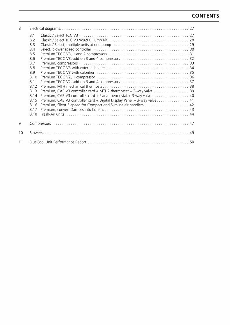
8 Electrical diagrams. . . . . . . . . . . . . . . . . . . . . . . . . . . . . . . . . . . . . . . . . . . . . . . . . . . . . . . . . . . . 27
8.1 Classic / Select TCC V3 . . . . . . . . . . . . . . . . . . . . . . . . . . . . . . . . . . . . . . . . . . . . . . . . . . . 278.2 Classic / Select TCC V3 WB200 Pump Kit . . . . . . . . . . . . . . . . . . . . . . . . . . . . . . . . . . . . . 288.3 Classic / Select, multiple units at one pump . . . . . . . . . . . . . . . . . . . . . . . . . . . . . . . . . . . 298.4 Select, blower speed controller . . . . . . . . . . . . . . . . . . . . . . . . . . . . . . . . . . . . . . . . . . . . 308.5 Premium TECC V3, 1 and 2 compressors. . . . . . . . . . . . . . . . . . . . . . . . . . . . . . . . . . . . . . 318.6 Premium TECC V3, add-on 3 and 4 compressors. . . . . . . . . . . . . . . . . . . . . . . . . . . . . . . . 328.7 Premium, compressors . . . . . . . . . . . . . . . . . . . . . . . . . . . . . . . . . . . . . . . . . . . . . . . . . . . 338.8 Premium TECC V3 with external heater. . . . . . . . . . . . . . . . . . . . . . . . . . . . . . . . . . . . . . . 348.9 Premium TECC V3 with calorifier. . . . . . . . . . . . . . . . . . . . . . . . . . . . . . . . . . . . . . . . . . . . 358.10 Premium TECC V2, 1 compressor . . . . . . . . . . . . . . . . . . . . . . . . . . . . . . . . . . . . . . . . . . . 368.11 Premium TECC V2, add-on 3 and 4 compressors . . . . . . . . . . . . . . . . . . . . . . . . . . . . . . . 378.12 Premium, MTH mechanical thermostat . . . . . . . . . . . . . . . . . . . . . . . . . . . . . . . . . . . . . . . 388.13 Premium, CAB V3 controller card + MTH2 thermostat + 3-way valve. . . . . . . . . . . . . . . . . 398.14 Premium, CAB V3 controller card + Plana thermostat + 3-way valve . . . . . . . . . . . . . . . . . 408.15 Premium, CAB V3 controller card + Digital Display Panel + 3-way valve . . . . . . . . . . . . . . . 418.16 Premium, Silent 5-speed for Compact and Slimline air handlers. . . . . . . . . . . . . . . . . . . . . 428.17 Premium, convert Danfoss into Lizhan. . . . . . . . . . . . . . . . . . . . . . . . . . . . . . . . . . . . . . . . 438.18 Fresh-Air units. . . . . . . . . . . . . . . . . . . . . . . . . . . . . . . . . . . . . . . . . . . . . . . . . . . . . . . . . . 44
9 Compressors . . . . . . . . . . . . . . . . . . . . . . . . . . . . . . . . . . . . . . . . . . . . . . . . . . . . . . . . . . . . . . . 47
10 Blowers . . . . . . . . . . . . . . . . . . . . . . . . . . . . . . . . . . . . . . . . . . . . . . . . . . . . . . . . . . . . . . . . . . . . 49
11 BlueCool Unit Performance Report . . . . . . . . . . . . . . . . . . . . . . . . . . . . . . . . . . . . . . . . . . . . . . . 50

Digital Control Panel operation and settings
1 Digital Control Panel operation and settings
1.1 Operating and programming level 1
Higher values
Chiller Control
Cool
Auto
Heat
Read-out
Blower speed Lower values Set-up / programming
Cool cycle mode
Automatic mode
Heat cycle mode
On / Off
Higher values (Sun)
Read-out (0)
Lower values (Snow flake)
Blower speed Function (F)
Cool cycle mode
Automatic operation
Heat cycle mode
On / Off
ON Push 1x, display will show ON. During first start-up display will also flash the current frequency (50H = 50 Hz). After INIT, finally the room temperature will appear. Air-blower or chilled water pump (Premium only) will start. Depending on controller setting unit will start in cooling or heating mode. In case error codes appear, see trouble shooting.
OFF Push 1x, unit and display will automatically shut-off when running.
MEMO(NENO) Push 1x, to memorise new settings during programming.
RETURN Push 1x, display will return to room temperature when programming.
FUNCTION Push 1x, shows b.. for blower setting.
Push 2x, shows E.. or H.. for coil or water temperature.
Push 3x, shows CODE, enter code for access programming level 2. (Default=64) Classic/Select only
Change b.. or enter CODE by pushing up or down key.
NEXT LINE Push 1x, for next line and memorise new setting.
DOWN Push 1x will show actual setpoint, again to lower setpoint.
BLOWER SPEED Shows actual blower speed setting, bA automatic control or b1-b5 manual, adjustable by up or down.
UP Push 1x will show actual setpoint, again to raise setpoint.
During operation failure codes might appear on the display (see troubleshooting), when these are solved, controller will restart within 60 seconds.When the same failure occurs 6 times within 30 minutes the unit will stop completely without restart, LEDs will flash in the display until cause is solved. The counter is reset after 5 minutes of compressor operation.Failure code A01 has a time delay of approximately 40 seconds to avoid cut-out during start-up.
6

Digital Control Panel operation and settings
1.2 Entering programming menu level 2
• When security CODE is activated, push FUNCTION when unit is in operation till CODE appears in the display.
• Set security CODE by pushing UP or DOWN and confirm with FUNCTION (Default = 64).
• In case security CODE is not activated you will have direct access.
• Scroll through settings by pushing FUNCTION, values can be set by UP or DOWN keys and confirmed by FUNCTION for next line.
• To leave this menu push ON/OFF, MEMO will be shown shortly and new settings will be memorised.
1.3 Entering programming menu level 3
• Set setpoint temperature on 15 °C or 29 °C and switch off the controller.
• Push UP and DOWN simultaneously till display lights up.
• Set security CODE when activated by pushing UP or DOWN and confirm with FUNCTION (Default = 64).
• Scroll through settings by pushing FUNCTION, values can be set by UP or DOWN keys and confirmed by FUNCTION for next line.
• To leave this menu push ON/OFF, MEMO will be shown shortly and new settings will be memorised.
7
Programming Premium Unit
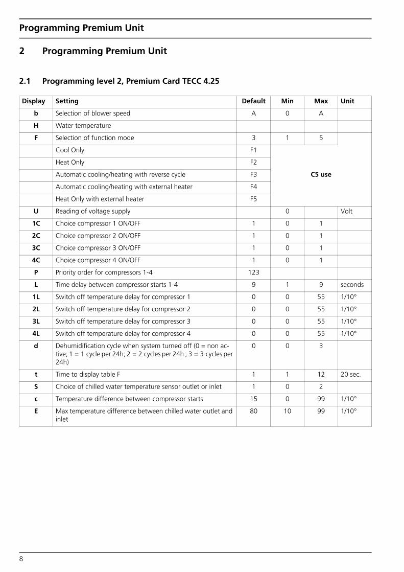
2 Programming Premium Unit
2.1 Programming level 2, Premium Card TECC 4.25
Display Setting Default Min Max Unit
b Selection of blower speed A 0 A
H Water temperature
F Selection of function mode 3 1 5
Cool Only F1
Heat Only F2
Automatic cooling/heating with reverse cycle F3 C5 use
Automatic cooling/heating with external heater F4
Heat Only with external heater F5
U Reading of voltage supply 0 Volt
1C Choice compressor 1 ON/OFF 1 0 1
2C Choice compressor 2 ON/OFF 1 0 1
3C Choice compressor 3 ON/OFF 1 0 1
4C Choice compressor 4 ON/OFF 1 0 1
P Priority order for compressors 1-4 123
L Time delay between compressor starts 1-4 9 1 9 seconds
1L Switch off temperature delay for compressor 1 0 0 55 1/10°
2L Switch off temperature delay for compressor 2 0 0 55 1/10°
3L Switch off temperature delay for compressor 3 0 0 55 1/10°
4L Switch off temperature delay for compressor 4 0 0 55 1/10°
d Dehumidification cycle when system turned off (0 = non ac-tive; 1 = 1 cycle per 24h; 2 = 2 cycles per 24h ; 3 = 3 cycles per 24h)
0 0 3
t Time to display table F 1 1 12 20 sec.
S Choice of chilled water temperature sensor outlet or inlet 1 0 2
c Temperature difference between compressor starts 15 0 99 1/10°
E Max temperature difference between chilled water outlet and inlet
80 10 99 1/10°
8

Programming Premium Unit
2.2 Programming level 3 at 29 °C, Premium Card TECC 4.25
Display Setting Default Min Max Unit
0 Lower cut-out value in cool mode for chilled water tempera-ture outlet
4 0 15 °
1 Cut-in value in cool mode for chilled water temperature outlet 7 2 18 °
2 Higher cut-out value in heat mode for chilled water tempera-ture outlet
40 30 49 °
3 Cut-in value in heat mode for chilled water temperature outlet 37 27 52 °
4 Calibration chilled water temperature 0 -55 55 1/10°
5 Time for display standby 15 5 99 minutes
6 Calibration of chilled water temperature inlet 0 -55 55 1/10°
7 Calibration of air temperature 0 -55 55 1/10°
8 Calibration of voltage under 50 Hz 0 -30 50
9 Select function of relais 0 0 3
Operating as staging relay 0
Controlling 3 way valve air handler by TECC card 1
Alarm indication 2
Cycle indication 3 For C5 use
A Calibration of voltage under 60 Hz -10 -30 50
b Program Version 4.2*
c Lower cut-out value in cool mode for chilled water tempera-ture inlet
6 0 15 °
d Cut-in value in cool mode for chilled water temperature inlet 9 2 18 °
E Higher cut-out value in heat mode for chilled water tempera-ture inlet
40 30 49 °
F Cut-in value in heat mode for chilled water temperature inlet 37 27 52 °
9
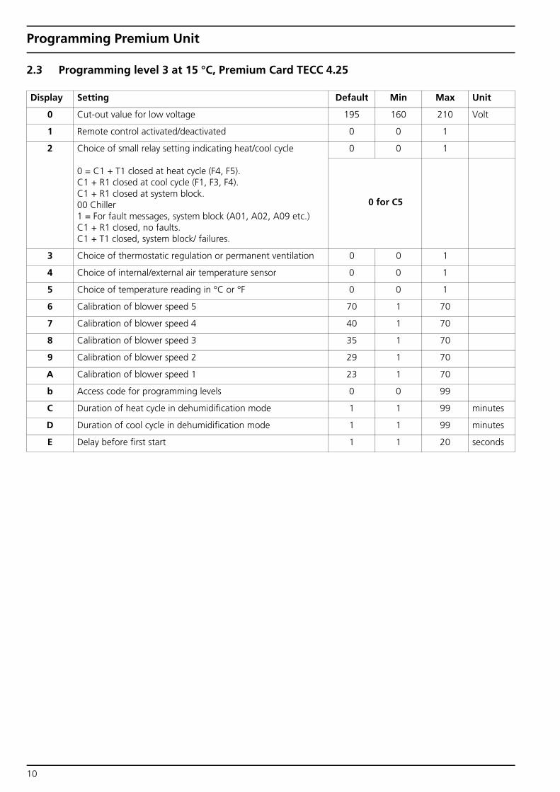
Programming Premium Unit
2.3 Programming level 3 at 15 °C, Premium Card TECC 4.25
Display Setting Default Min Max Unit
0 Cut-out value for low voltage 195 160 210 Volt
1 Remote control activated/deactivated 0 0 1
2 Choice of small relay setting indicating heat/cool cycle
0 = C1 + T1 closed at heat cycle (F4, F5). C1 + R1 closed at cool cycle (F1, F3, F4). C1 + R1 closed at system block. 00 Chiller1 = For fault messages, system block (A01, A02, A09 etc.) C1 + R1 closed, no faults.C1 + T1 closed, system block/ failures.
0 0 1
0 for C5
3 Choice of thermostatic regulation or permanent ventilation 0 0 1
4 Choice of internal/external air temperature sensor 0 0 1
5 Choice of temperature reading in °C or °F 0 0 1
6 Calibration of blower speed 5 70 1 70
7 Calibration of blower speed 4 40 1 70
8 Calibration of blower speed 3 35 1 70
9 Calibration of blower speed 2 29 1 70
A Calibration of blower speed 1 23 1 70
b Access code for programming levels 0 0 99
C Duration of heat cycle in dehumidification mode 1 1 99 minutes
D Duration of cool cycle in dehumidification mode 1 1 99 minutes
E Delay before first start 1 1 20 seconds
10

Programming Classic Unit
3 Programming Classic Unit
3.1 Programming level 2, Classic Card TCC 5.25
3.2 Programming level 3 at 29 °C, Classic Card TCC 5.25
Display Setting Default Min Max Unit
b Selection of blower speed A 0 A
F Selection of function mode 3 1 5
U Reading of voltage supply 0 Volt
1C Choice compressor 1 ON/OFF 1 0 1
d Dehumidification cycle when system turned off (0 = non ac-tive; 1 = 1 cycle per 24h; 2 = 2 cycles per 24h ; 3 = 3 cycles per 24h)
0 0 3
t Time to display table F 5 1 5 20 sec.
Display Setting Default Min Max Unit
0 Lower cut-out value in cool mode for evaporator temperature 0 -4 15 °
1 Cut-in value in cool mode for evaporator temperature 7 2 18 °
2 Higher cut-out value in heat mode for evaporator temperature 45 30 50 °
3 Cut-in value in heat mode for evaporator temperature 38 27 47 °
4 Calibration evaporator temperature 0 -55 55 1/10°
5 Time for display standby 15 5 99 minutes
6 Time delay for first compressor start 1 1 20 seconds
7 Calibration of air temperature 0 -55 55 1/10°
8 Calibration of voltage under 50 Hz 0 -30 50
9 Time delay for compressor restart after end of cycle cut-out 2 1 99 minutes
A Calibration of voltage under 60 Hz 0 -30 50
B Program version v5.2*
C Mode choice for pump exit 0 0 1
D Minimum voltage for pump exit 12 12 18 Volt
E Maximum voltage for pump exit 18 12 18 Volt
F Mode choice for water valve exit 1 0 1
11
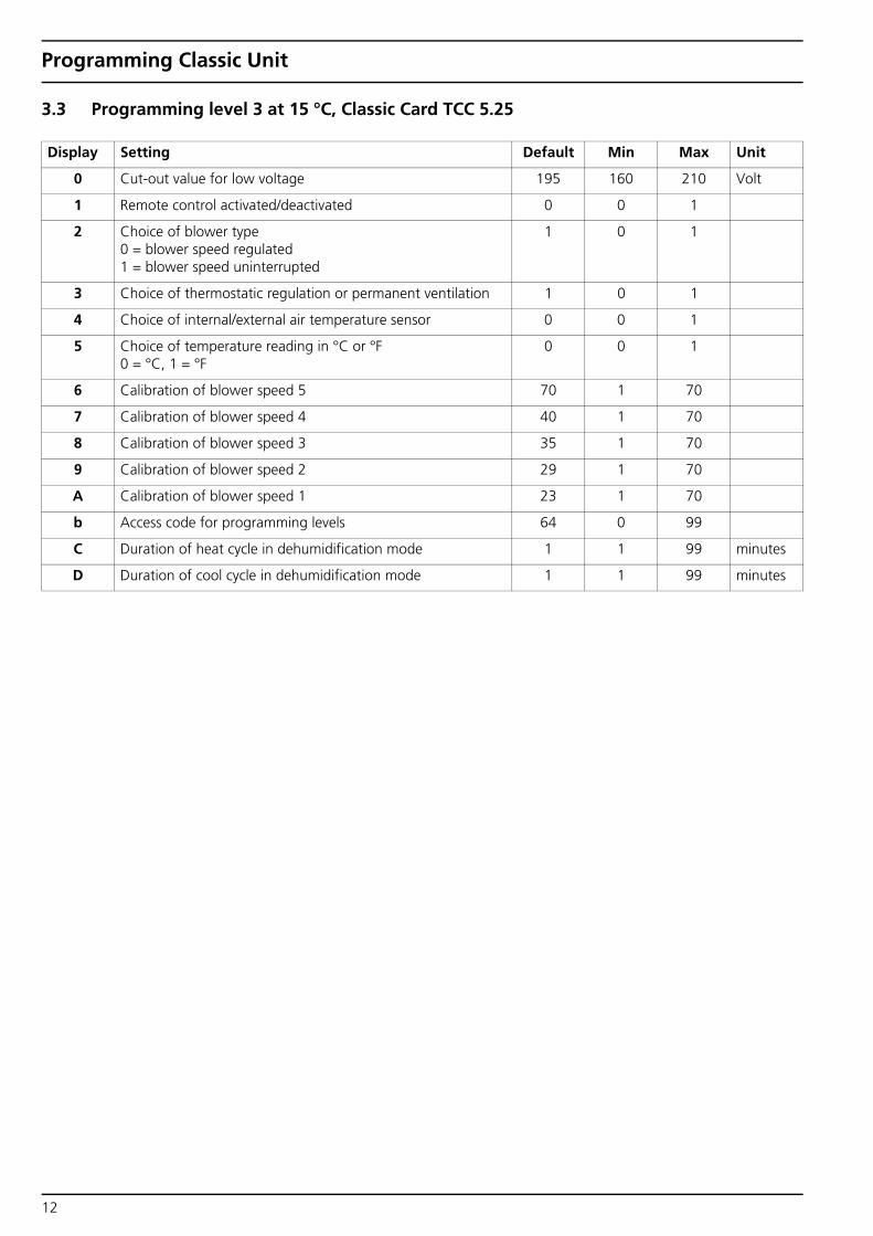
Programming Classic Unit
3.3 Programming level 3 at 15 °C, Classic Card TCC 5.25
Display Setting Default Min Max Unit
0 Cut-out value for low voltage 195 160 210 Volt
1 Remote control activated/deactivated 0 0 1
2 Choice of blower type 0 = blower speed regulated 1 = blower speed uninterrupted
1 0 1
3 Choice of thermostatic regulation or permanent ventilation 1 0 1
4 Choice of internal/external air temperature sensor 0 0 1
5 Choice of temperature reading in °C or °F 0 = °C, 1 = °F
0 0 1
6 Calibration of blower speed 5 70 1 70
7 Calibration of blower speed 4 40 1 70
8 Calibration of blower speed 3 35 1 70
9 Calibration of blower speed 2 29 1 70
A Calibration of blower speed 1 23 1 70
b Access code for programming levels 64 0 99
C Duration of heat cycle in dehumidification mode 1 1 99 minutes
D Duration of cool cycle in dehumidification mode 1 1 99 minutes
12
Programming Cabin Controls
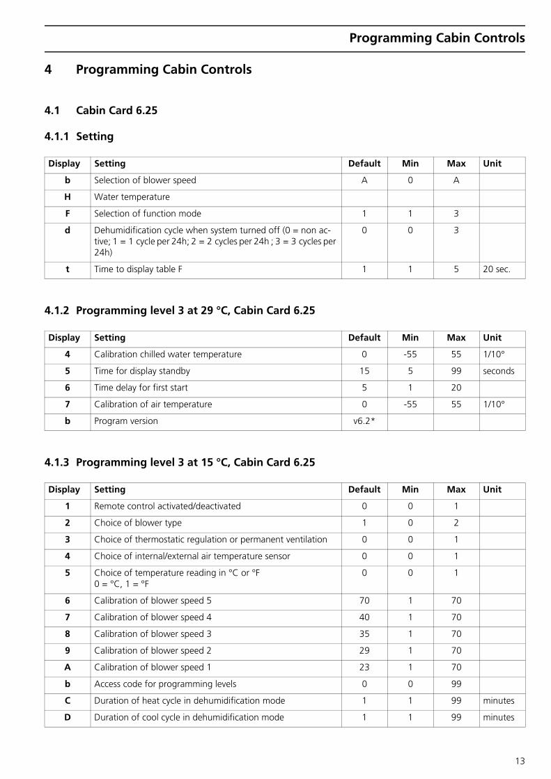
4 Programming Cabin Controls
4.1 Cabin Card 6.25
4.1.1 Setting
4.1.2 Programming level 3 at 29 °C, Cabin Card 6.25
4.1.3 Programming level 3 at 15 °C, Cabin Card 6.25
Display Setting Default Min Max Unit
b Selection of blower speed A 0 A
H Water temperature
F Selection of function mode 1 1 3
d Dehumidification cycle when system turned off (0 = non ac-tive; 1 = 1 cycle per 24h; 2 = 2 cycles per 24h ; 3 = 3 cycles per 24h)
0 0 3
t Time to display table F 1 1 5 20 sec.
Display Setting Default Min Max Unit
4 Calibration chilled water temperature 0 -55 55 1/10°
5 Time for display standby 15 5 99 seconds
6 Time delay for first start 5 1 20
7 Calibration of air temperature 0 -55 55 1/10°
b Program version v6.2*
Display Setting Default Min Max Unit
1 Remote control activated/deactivated 0 0 1
2 Choice of blower type 1 0 2
3 Choice of thermostatic regulation or permanent ventilation 0 0 1
4 Choice of internal/external air temperature sensor 0 0 1
5 Choice of temperature reading in °C or °F 0 = °C, 1 = °F
0 0 1
6 Calibration of blower speed 5 70 1 70
7 Calibration of blower speed 4 40 1 70
8 Calibration of blower speed 3 35 1 70
9 Calibration of blower speed 2 29 1 70
A Calibration of blower speed 1 23 1 70
b Access code for programming levels 0 0 99
C Duration of heat cycle in dehumidification mode 1 1 99 minutes
D Duration of cool cycle in dehumidification mode 1 1 99 minutes
13

Programming Cabin Controls
4.2 CAB V3 Card MTH2/PLANA
Version CAB 9.03
Display Setting Default Air Handler
SP Speed Position selector switch SP... (0/1/2/3)
•
tF 00 = blower off 01 • 1 Setting fan speed level 1 (low) 23 •
2 Setting fan speed level 2 35 •
3 Setting fan speed level 3 (high) 70 •
14
Programming Fresh-Air
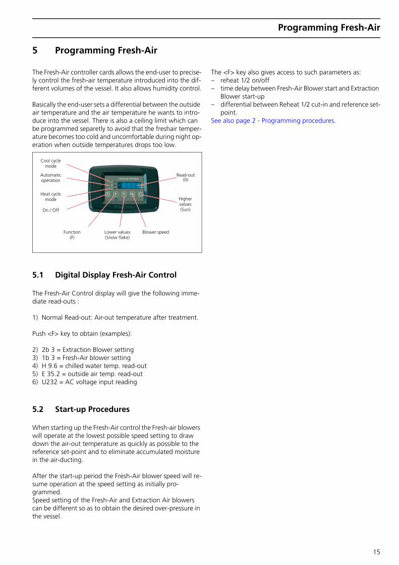
5 Programming Fresh-Air
The Fresh-Air controller cards allows the end-user to precise-ly control the fresh-air temperature introduced into the dif-ferent volumes of the vessel. It also allows humidity control.
Basically the end-user sets a differential between the outside air temperature and the air temperature he wants to intro-duce into the vessel. There is also a ceiling limit which can be programmed separetly to avoid that the freshair temper-ature becomes too cold and uncomfortable during night op-eration when outside temperatures drops too low.
5.1 Digital Display Fresh-Air Control
The Fresh-Air Control display will give the following imme-diate read-outs :
1) Normal Read-out: Air-out temperature after treatment.
Push <F> key to obtain (examples):
2) 2b 3 = Extraction Blower setting3) 1b 3 = Fresh-Air blower setting4) H 9.6 = chilled water temp. read-out5) E 35.2 = outside air temp. read-out6) U232 = AC voltage input reading
5.2 Start-up Procedures
When starting up the Fresh-Air control the Fresh-air blowers will operate at the lowest possible speed setting to draw down the air-out temperature as quickly as possible to the reference set-point and to eliminate accumulated moisture in the air-ducting.
After the start-up period the Fresh-Air blower speed will re-sume operation at the speed setting as initially pro-grammed. Speed setting of the Fresh-Air and Extraction Air blowers can be different so as to obtain the desired over-pressure in the vessel.
The <F> key also gives access to such parameters as: – reheat 1/2 on/off – time delay between Fresh-Air Blower start and Extraction
Blower start-up – differential between Reheat 1/2 cut-in and reference set-
point. See also page 2 - Programming procedures.
Higher values (Sun)
Read-out (0)
Lower values (Snow flake)
Blower speed Function (F)
Cool cycle mode
Automatic operation
Heat cycle mode
On / Off
15

Programming Fresh-Air
5.3 Cycle Determination
Here-above drawings explain the operating window with the associated setpoints and reheat differentials.
The choice between heat cycle and cool cycle is done auto-matically by the controller card depending on the chilled water temperature as recorded by the controller card. The switching temperature is determines by the programming lines 3 and 4 (snow key). Factory settings are as following: Lower ceiling : 18 °C Higher ceiling : 20 °C
This means that below 18 °C chilled water temperature the fresh-air controller considers that cool cycle operation is re-quired; above 20 °C the controller switches to heat cycle op-eration. Between 18 °C and 20 °C the controllers suspends controlling activity and waits to see which cycle is definitely adopted.
5.4 Blower Speed Regulation
As already explained blower speed can be set in a differen-tial way between the Fresh-Air blowers (1b) and the Extrac-tion Blowers (2b).
In addition the Fresh-Air blowers can be set manually on a fixed speed without any reference to the chilled water tem-perature and/or outside/inside air temperatures or start-up procedure. This choice can be made in programming mode (sun key - line 9).
5.5 Access Code
The end-user can deny access to all program settings by in-troducing an access code (see page 8 - code <b>). Blower speed and setpoints always remain accessible.
Once an access code is validated, the digital panel will show <Code> if the end-user tries to access other functions then blower speed or set-point. To gain full access push the sun key to reach the code number as programmed and push the <F> key again to gain access to full program settings.
5.6 Visual Error Codes - Digital Display
The following malfunctions will be displayed directly on the digital display by a code and will be followed by a system halt. Whenever any of these codes appear the system is stopped for approx. 60 seconds and then a re-start is attempted.
If for more than 30 minutes the same malfunction occurs, the system will be stopped completely and the error-code will become steady.
No more re-starts will be attempted and the user will have to re-set the system by pushing the ON/OFF switch or by temporarily cutting out the AC supply to the system.
35°C24°C22°C20°C
5°C 24°C22°C21.5°C
Reference Setpoint
Example of operating window setting - Fresh-Air Control - Cool Cycle
Reheat 2 cuts in at 20° - cuts out at 22° Cooling Coil 3 way valve cuts out at 20° and cuts in again at 22°
Reheat 1 cuts in at 22° - cuts out at 24°
Reference Setpoint Ceiling Limit = 20° - i.e. reference setpoint will always be 20 °C or higher
Outside air temperature
Differential = 16 °C - Prog. Line 0 - Sun Key
Outside air temperature
Differential = 18 °C - Prog. Line 2 - Sun Key
Reference Setpoint Ceiling Limit = 24° - i.e. reference setpoint will always be 24 °C or lower
Reference Setpoint
Reheat 1 cuts out at 24° - cuts in at 22° Heating Coil 3 way valve cuts out at 24° and cuts in again at 22°
Reheat 2 cuts out at 22° - cuts in at 21.5°
Example of operating window setting - Fresh-Air Control - Heat Cycle
16

Programming Fresh-Air
List of error-codes and nature of malfunction:
Code <AAA> : Persistent low voltage (voltage below 185 V) for more than 5 seconds.
<A09> - absent or defective external air sensor
<A10> - absent or defective treated air sensor
<EEEE> - absent or defective chilled water sensor
Code A02 : Check the straps on HP/BP connectors
5.7 Programming Parameters
Three levels of programming parameters are available to the end user:
A) through <F> (Function) key
2b 3 = Extraction blower(s) - 5 manual speeds can be pro-grammed - last setting is memorized.
1b 3 = Fresh-Air blowers - 5 manual speeds can be pro-grammed - last setting is memorized.
1r01 = reheat N° 1 activated.
1r00 = reheat N°1 on standby.
2r01 = reheat N° 2 activated.
2r00 = reheat N° 2 on standby.
L 09 = time delay between 1b (Fresh-air blower) and 2b (Ex-traction blowers) in seconds.
1L2.0 = temperature differential reheat N° 1 operation as measured from reference setpoint (2.0 °C).
2L2.5 = temperature differential reheat N° 2 operation as measured from reference setpoint (2.5 °C).
d 0 = number of dehumidifying cycles per 24 Hours (if such cycle is programmed in absence - see programming by snow key).
t 1 = number of minutes before display switches back to air-out temperature read-out after the <F> key is used.
B) Programming through Sun Key
To enter this programming mode, first switch off Display by on/off key, then push Sun Key for 3 seconds. You will now enter Sun Key programming mode as following:
0 16 = temperature differential in °C for cool cycle opera-tion. Max = 25 °C - mini = 5 °C.
1 20 = max lower ceiling of reference setpoint cool cycle. Mini = 10° - max = 30 °C.
2 18 = temperature differential in °C for heat cycle opera-tion. Max = 35 °C - mini = 10 °C.
3 24 = max. higher ceiling for reference setpoint heat cycle. Mini = 10° - max. = 35 °C.
4 0.0 = temp. read out calibration chilled water sensor (from -9.9 to +9.9 °C).
5 15 = number of minutes before the Digital Display switch-es into sleep mode. Max. = 99 minutes.
6 0.0 = outside air temperature sensor calibration.
7 0.0 = air-out (after treatment) temperature calibration.
8 00 = AC voltage reading calibration 50 Hz.
9 01 = choice between normal procedure Fresh-Air blower operation of manual fixed speed. 0 = manual speed regardless of all operating procedures.
a 00 = AC voltage reading calibration - 60 Hz
17
Programming Fresh-Air
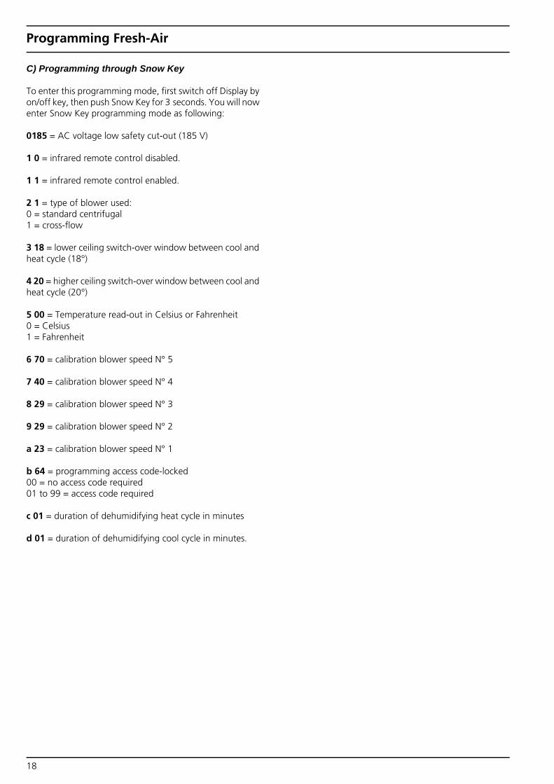
C) Programming through Snow Key
To enter this programming mode, first switch off Display by on/off key, then push Snow Key for 3 seconds. You will now enter Snow Key programming mode as following:
0185 = AC voltage low safety cut-out (185 V)
1 0 = infrared remote control disabled.
1 1 = infrared remote control enabled.
2 1 = type of blower used: 0 = standard centrifugal 1 = cross-flow
3 18 = lower ceiling switch-over window between cool and heat cycle (18°)
4 20 = higher ceiling switch-over window between cool and heat cycle (20°)
5 00 = Temperature read-out in Celsius or Fahrenheit 0 = Celsius 1 = Fahrenheit
6 70 = calibration blower speed N° 5
7 40 = calibration blower speed N° 4
8 29 = calibration blower speed N° 3
9 29 = calibration blower speed N° 2
a 23 = calibration blower speed N° 1
b 64 = programming access code-locked 00 = no access code required 01 to 99 = access code required
c 01 = duration of dehumidifying heat cycle in minutes
d 01 = duration of dehumidifying cool cycle in minutes.
18

Programming Fresh-Air
5.8 Cabin Card 6.25
5.8.1 Setting
5.8.2 Programming level 3 at 29 °C, Cabin Card 6.25
5.8.3 Programming level 3 at 15 °C, Cabin Card 6.25
Display Setting Default Min Max Unit
b Selection of blower speed A 0 A
H Water temperature
F Selection of function mode 1 1 3
d Dehumidification cycle when system turned off (0 = non ac-tive; 1 = 1 cycle per 24h; 2 = 2 cycles per 24h ; 3 = 3 cycles per 24h)
0 0 3
t Time to display table F 1 1 5 20 sec.
Display Setting Default Min Max Unit
4 Calibration chilled water temperature 0 -55 55 1/10°
5 Time for display standby 15 5 99 seconds
6 Time delay for first start 5 1 20
7 Calibration of air temperature 0 -55 55 1/10°
b Program version v6.2*
Display Setting Default Min Max Unit
1 Remote control activated/deactivated 0 0 1
2 Choice of blower type 1 0 2
3 Choice of thermostatic regulation or permanent ventilation 0 0 1
4 Choice of internal/external air temperature sensor 0 0 1
5 Choice of temperature reading in °C or °F 0 = °C, 1 = °F
0 0 1
6 Calibration of blower speed 5 70 1 70
7 Calibration of blower speed 4 40 1 70
8 Calibration of blower speed 3 35 1 70
9 Calibration of blower speed 2 29 1 70
A Calibration of blower speed 1 23 1 70
b Access code for programming levels 0 0 99
C Duration of heat cycle in dehumidification mode 1 1 99 minutes
D Duration of cool cycle in dehumidification mode 1 1 99 minutes
19

Programming Fresh-Air
5.9 CAB V3 Card MTH2/PLANA
Version CAB 9.03
Display Setting Default Air Handler
SP Speed Position selector switch SP... (0/1/2/3)
•
tF 00 = blower off 01 • 1 Setting fan speed level 1 (low) 23 •
2 Setting fan speed level 2 35 •
3 Setting fan speed level 3 (high) 70 •
20

Trouble Shooting
6 Trouble Shooting
6.1 Failure codes and trouble shooting
Failure code
Description Possible cause Solution
AAA Low Voltage Low voltage cut-out. Power supply was over 5 sec lower than controller setting. Probably caused by long length power supply cable or overload.
Check setting, default 195 V. Don't set below 195 V to avoid damages to the compressor or to expire warranty. Improve power supply.
A01 Low pressure cut-out compressor 1 (Classic > 20.000 BTU) 15 - 35 PSI / 1 - 2.4 bar
Defective pressure sensor or open/short circuit.
Check wiring or replace pressure sensor on Schrader valve.
COOLING MODE: - Insufficient evaporator water flow
(Premium) or air flow (Classic). - Air lock in water circuit (Premium) or
broken circulation pump.
Check water or air flow. ΔT evaporator in/out minimum 4K. Bleed Premium water system; check pump operation.
HEATING MODE:- Insufficient seawater flow or seawater
to cold. - Blocked sea-water strainer or not
primed.
Check discharge water volume. V= 8 l/min (or > 30,000 BTU V= 18 l/min). ΔT in/out minimum 4K. When T seawater < 4 °C: preheating necessary. Clean strainer and bleed seawater circuit.
Lack of refrigerant. Refrigerant leak check.
A02 High pressure cut-out compressor 1 350 - 250 PSI / 24 - 17.24 bar
Defective pressure sensor or open/short circuit.
Check sensor and wiring. Replace sensor on Schrader if necessary.
COOLING MODE:- Insufficient seawater cooling or
defective circulation pump.- Blocked seawater strainer or not
primed.
Check discharge water volume. V= 8 l/min (or > 30,000 BTU V= 18 l/min). Clean strainer and bleed sea-water circuit.
HEATING MODE:- Insufficient evaporator water flow
(Premium) or air flow (Classic).- Air lock in chilled water circuit
(Premium) or broken circulation pump.
Check water or air-flow. ΔT evaporator in/out minimum 4K. Bleed chilled water system or check pomp operation.
A03 Low pressure cut-out compressor 2 (Premium only)
See A01 See A01
A04 High pressure cut-out compressor 2 (Premium only)
See A02 See A02
A05 Low pressure cut-out compressor 3 (Premium only)
See A01 See A01
A06 High pressure cut-out compressor 3 (Premium only)
See A02 See A02
21
Trouble Shooting
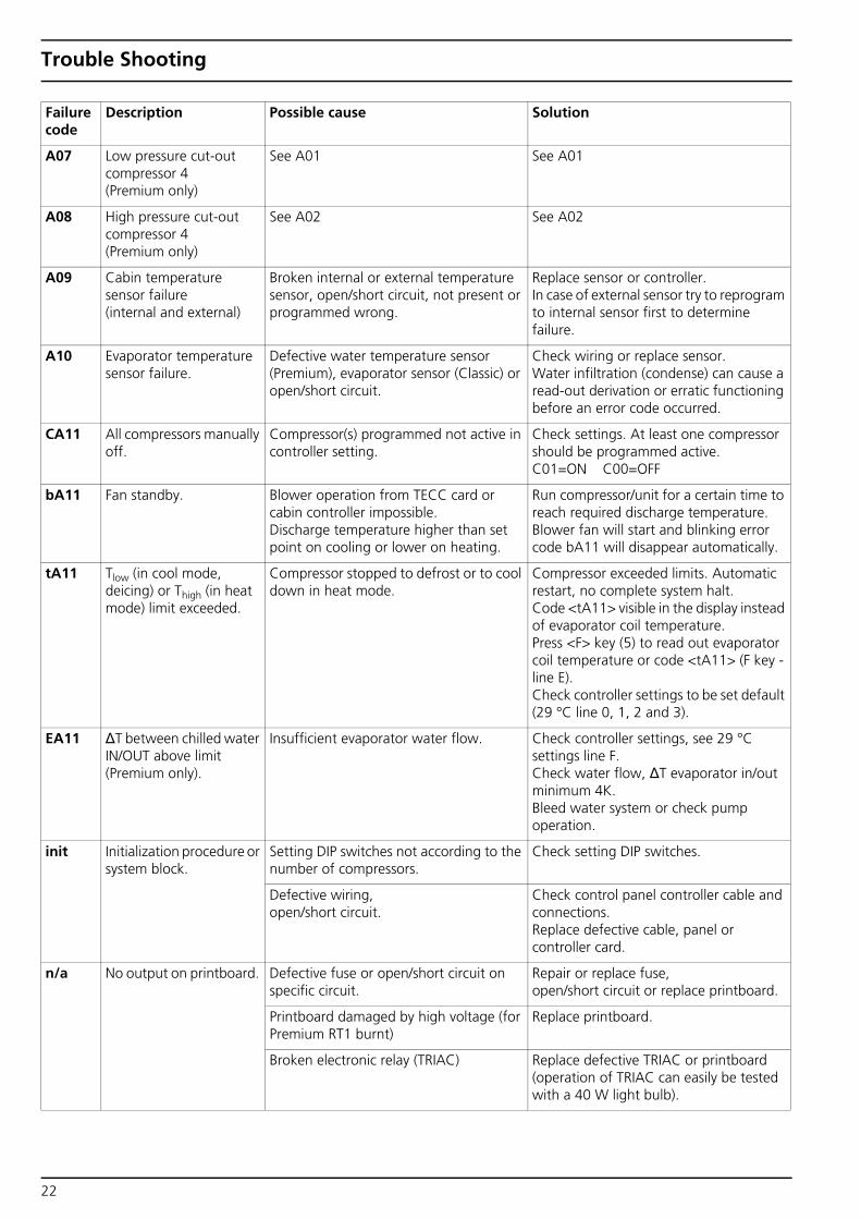
A07 Low pressure cut-out compressor 4 (Premium only)
See A01 See A01
A08 High pressure cut-out compressor 4 (Premium only)
See A02 See A02
A09 Cabin temperature sensor failure (internal and external)
Broken internal or external temperature sensor, open/short circuit, not present or programmed wrong.
Replace sensor or controller. In case of external sensor try to reprogram to internal sensor first to determine failure.
A10 Evaporator temperature sensor failure.
Defective water temperature sensor (Premium), evaporator sensor (Classic) or open/short circuit.
Check wiring or replace sensor. Water infiltration (condense) can cause a read-out derivation or erratic functioning before an error code occurred.
CA11 All compressors manually off.
Compressor(s) programmed not active in controller setting.
Check settings. At least one compressor should be programmed active. C01=ON C00=OFF
bA11 Fan standby. Blower operation from TECC card or cabin controller impossible. Discharge temperature higher than set point on cooling or lower on heating.
Run compressor/unit for a certain time to reach required discharge temperature. Blower fan will start and blinking error code bA11 will disappear automatically.
tA11 Tlow (in cool mode, deicing) or Thigh (in heat mode) limit exceeded.
Compressor stopped to defrost or to cool down in heat mode.
Compressor exceeded limits. Automatic restart, no complete system halt. Code <tA11> visible in the display instead of evaporator coil temperature. Press <F> key (5) to read out evaporator coil temperature or code <tA11> (F key - line E). Check controller settings to be set default (29 °C line 0, 1, 2 and 3).
EA11 ΔT between chilled water IN/OUT above limit (Premium only).
Insufficient evaporator water flow. Check controller settings, see 29 °C settings line F. Check water flow, ΔT evaporator in/out minimum 4K.Bleed water system or check pump operation.
init Initialization procedure or system block.
Setting DIP switches not according to the number of compressors.
Check setting DIP switches.
Defective wiring, open/short circuit.
Check control panel controller cable and connections. Replace defective cable, panel or controller card.
n/a No output on printboard. Defective fuse or open/short circuit on specific circuit.
Repair or replace fuse, open/short circuit or replace printboard.
Printboard damaged by high voltage (for Premium RT1 burnt)
Replace printboard.
Broken electronic relay (TRIAC) Replace defective TRIAC or printboard (operation of TRIAC can easily be tested with a 40 W light bulb).
Failure code
Description Possible cause Solution
22

Trouble Shooting
n/a Compressor not running. Broken compressor or open/short circuit compressor wiring.
Repair wiring or replace defective compressor.
Compressor overload or broken Overload Protector (OLP) on top of the compressor.
Wait a certain time to cool down or replace defective OLP.
Compressor settings incorrect. Check settings, at least one compressor should be programmed active. C01=ON C00=OFF
n/a Seawater pump(s) running directly after power up controller.
Wiring pump 1 (seawater) mixed-up with pump 2 (chilled water).
Check wiring.
n/a Compressor starts or stops continuously.
Lack of chilled water. Check for leaks in water system.
n/a No or insufficient cooling or heating performance.
Bad air flow or water flow, filthy or blocked circulation.
Ensure air or water flow (see A01 and/or A02).
Lack of refrigerant. Lack of refrigerant mostly recognized by a low static pressure before start-up and non-fluctuating LP associated with a low HP pressure reading. Check for refrigerant leaks, repair if necessary and charge required amount of refrigerant.
Oil lock. Operate the unit in heat cycle. Intervention by a refrigerant specialist might be necessary. Technical Memo available.
Blocked refrigerant circuit. (Drier, capillary or expansion valve).
To be determined by a refrigerant specialist. Technical Memo available.
Bad compressor. To be determined by a refrigerant specialist.
n/a Pumps running continuously.
When additional relays are used to operate pumps a small leaking current from the printboard may operate the relay continuously.
Remove R56 + C24 and/or R57 + C27 from the printboard.
n/a Inaccurate temperature read-out of room / ambient temperature, water temperature (premium) or evaporator temperature (classic).
Temperature sensor not installed on the right position, interference by environment or read-out deviation.
Check for interference by direct sunlight, heat radiation from components near to the sensor.Calibrate sensor.Replace defective sensor.
n/a Blower not running. Defective fuse or open/short circuit on specific circuit.
Repair or replace fuse, open/short circuit or replace print board.
Check fan by testing with direct current on fan. Replace fan if still not running.
Check if blower setting is not at B0. Put blower setting to B1 - BA.
Failure code
Description Possible cause Solution
23
Trouble Shooting
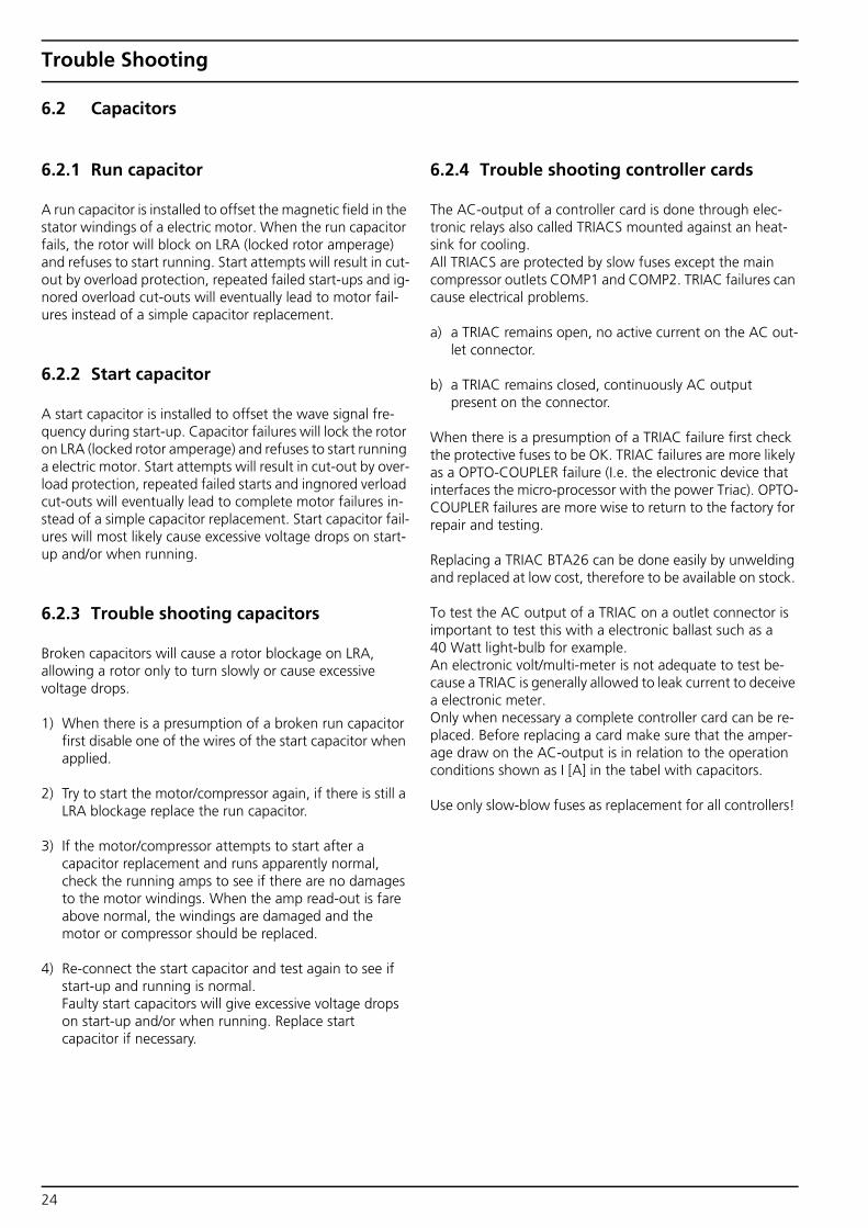
6.2 Capacitors
6.2.1 Run capacitor
A run capacitor is installed to offset the magnetic field in the stator windings of a electric motor. When the run capacitor fails, the rotor will block on LRA (locked rotor amperage) and refuses to start running. Start attempts will result in cut-out by overload protection, repeated failed start-ups and ig-nored overload cut-outs will eventually lead to motor fail-ures instead of a simple capacitor replacement.
6.2.2 Start capacitor
A start capacitor is installed to offset the wave signal fre-quency during start-up. Capacitor failures will lock the rotor on LRA (locked rotor amperage) and refuses to start running a electric motor. Start attempts will result in cut-out by over-load protection, repeated failed starts and ingnored verload cut-outs will eventually lead to complete motor failures in-stead of a simple capacitor replacement. Start capacitor fail-ures will most likely cause excessive voltage drops on start-up and/or when running.
6.2.3 Trouble shooting capacitors
Broken capacitors will cause a rotor blockage on LRA, allowing a rotor only to turn slowly or cause excessive voltage drops.
1) When there is a presumption of a broken run capacitor first disable one of the wires of the start capacitor when applied.
2) Try to start the motor/compressor again, if there is still a LRA blockage replace the run capacitor.
3) If the motor/compressor attempts to start after a capacitor replacement and runs apparently normal, check the running amps to see if there are no damages to the motor windings. When the amp read-out is fare above normal, the windings are damaged and the motor or compressor should be replaced.
4) Re-connect the start capacitor and test again to see if start-up and running is normal. Faulty start capacitors will give excessive voltage drops on start-up and/or when running. Replace start capacitor if necessary.
6.2.4 Trouble shooting controller cards
The AC-output of a controller card is done through elec-tronic relays also called TRIACS mounted against an heat-sink for cooling. All TRIACS are protected by slow fuses except the main compressor outlets COMP1 and COMP2. TRIAC failures can cause electrical problems.
a) a TRIAC remains open, no active current on the AC out-let connector.
b) a TRIAC remains closed, continuously AC output present on the connector.
When there is a presumption of a TRIAC failure first check the protective fuses to be OK. TRIAC failures are more likely as a OPTO-COUPLER failure (I.e. the electronic device that interfaces the micro-processor with the power Triac). OPTO-COUPLER failures are more wise to return to the factory for repair and testing.
Replacing a TRIAC BTA26 can be done easily by unwelding and replaced at low cost, therefore to be available on stock.
To test the AC output of a TRIAC on a outlet connector is important to test this with a electronic ballast such as a 40 Watt light-bulb for example. An electronic volt/multi-meter is not adequate to test be-cause a TRIAC is generally allowed to leak current to deceive a electronic meter. Only when necessary a complete controller card can be re-placed. Before replacing a card make sure that the amper-age draw on the AC-output is in relation to the operation conditions shown as I [A] in the tabel with capacitors.
Use only slow-blow fuses as replacement for all controllers!
24

Controller Cards
7 Controller Cards
7.1 Classic / Select
7.2 Premium
CPAC - TCCController V2
< 2004
CPAC - TCCController V3
2004 >
Fuses V2 series
Fuses V3 series: F1 Print board 315 mA F2 Pump 3.15 A F3 Valve 3.15 A F4 Fan 3.15 A
Dipswitch settings V2 series
WBCL000828
Chiller - TECCController V2
< 2006
Chiller - TECCController V3.1
2006 >
Fuses V2 series
Fuses V3 series: F1 Print board 315 mA F2 Fan 6.3 A F3 Valve 3.15 A F4 Pump 1 SW 3.15 A F5 Pump 2 CW 3.15 A
Dipswitch settings V2 series
WBCL000864
1 and 2 com-pressors
3 and 4 com-pressors
25

Controller Cards
7.3 Air handler
Air handler - CAB Controller V2
< 2005
Fuses V3 models: F1 Print board 315 mA F2 Fan 6.3 A
Air handler - CAB Controller V3.1
2005 - 2006
Air handler - CAB Controller V3.2
2006 >
WBCL000860
26

Electrical diagrams
8 Electrical diagrams
8.1 Classic / Select TCC V3
br bl br bl br bl sw ws
sw sw rt gr ge
bl br sw gn
bl ws
Fuse
s:
F1 p
rint
315m
A
(115
V 6
30m
A)
F2 f
an 3
.15A
F3
val
ve 3
.15A
F4
pum
p 1
SW 3
.15
A
C
able
col
ours
bl
br
ge
gn
gr
rt sw
w
s
blue
br
own
yello
w
gree
n gr
ey
red
blac
k w
hite
4-w
ay r
ev. v
alve
Blo
wer
Seaw
ater
pu
mp
115/
230V
AC
sw
itch
bo
ard
Pres
sure
sw
itch
es
LP o
nly
for 1
6,00
0BT
U
and
mor
e
Ru
n c
apac
ito
r
Star
t ca
pac
ito
r (o
nly
for
16,0
00BT
U
and
mor
e)
Cap
acito
r an
d re
sist
or p
ump
*)
Dis
play
Exte
rnal
air
tem
p.
sens
or
Evap
orat
or t
emp.
se
nsor
compfan valve pump
Cap
acito
r an
d re
sist
or p
ump
*)
*)In
cas
e a
rela
y is
use
d, t
he
cont
rolle
r sh
ould
be
with
out
rela
ted
capa
cito
r an
d re
sist
or
27

Electrical diagrams
8.2 Classic / Select TCC V3 WB200 Pump Kit
bl br
IMPO
RTA
NT
For p
rope
r ope
ratio
n TC
C c
ontr
olle
r se
ttin
gs a
t se
tpoi
nt 2
9°C
, lin
e <
c>
mus
t be
set
at
01
Seaw
ater
pu
mp
TCC
pu
mp
ou
tlet
C
able
col
ours
bl
br
bl
ue
brow
n
Dis
play
compfan valve pump
Exte
rnal
air
tem
p.
sens
or
Evap
orat
or t
emp.
se
nsor
FUSE
/ V
OLT
AG
E SE
TTIN
G:
28

Electrical diagrams
8.3 Classic / Select, multiple units at one pump
IMPO
RTA
NT
The
TCC
con
trol
ler
card
of
each
uni
t sh
ould
be
with
out
capa
cito
r an
d re
sist
or a
t th
e re
late
d ou
tput
. Re
mov
e if
nece
ssar
y!
Co
mm
on
sea
wat
er
pu
mp
TCC
pu
mp
ou
tlet
un
it 1
115/
230V
AC
sw
itch
bo
ard
TCC
pu
mp
ou
tlet
un
it 2
TCC
pu
mp
ou
tlet
un
it 3
TCC
pu
mp
ou
tlet
un
it 4
29

Electrical diagrams
8.4 Select, blower speed controller
Blow
er s
peed
con
trol
ler
card
mou
nted
in g
rille
ba
se
115/
230V
AC
sup
ply
from
spl
itair
unit’
s el
ectr
ical
box
Blow
er e
lect
rical
te
rmin
als
Split
air
blow
er
mod
ule
GN
D
30

Electrical diagrams
8.5 Premium TECC V3, 1 and 2 compressors
SW
WS
SW RT
SW RT GE
GE
Fuse
s:
F1 P
CB
315m
A (1
15V
630
mA
) F2
fan
6.3
A
F3 v
alve
3.1
5A
F4 p
ump
1 SW
3.1
5A
F5 p
ump
2 C
W 3
.15A
Cab
le c
olou
rs
bl
br
ge
gn
gr
rt
sw
ws
blue
br
own
yello
w
gree
n gr
ey
red
blac
k w
hite
Rel
ay C
om
p. 1
Blo
wer
115/
230V
AC
sw
itch
bo
ard
Pres
sure
sw
itch
es
Dis
play
Exte
rnal
air
tem
p.
sens
or
Chi
lled
wat
er t
emp.
se
nsor
fan valve pump2C
apac
itor
and
resi
stor
pum
p2
*)
*)In
cas
e a
rela
y is
use
d, t
he c
ontr
olle
r sh
ould
be
with
out
rela
ted
capa
cito
r an
d re
sist
or
Cap
acito
r an
d re
sist
or p
ump
1 *)
pump1
fan Nvalve N
pum
p1
N
pum
p2
N
Not
use
d
4-w
ay r
ev. v
alve
Rel
ay C
om
p. 2
4-w
ay r
ev. v
alve
Seaw
ater
pu
mp
Ch
illed
wat
er p
um
p
31
Electrical diagrams
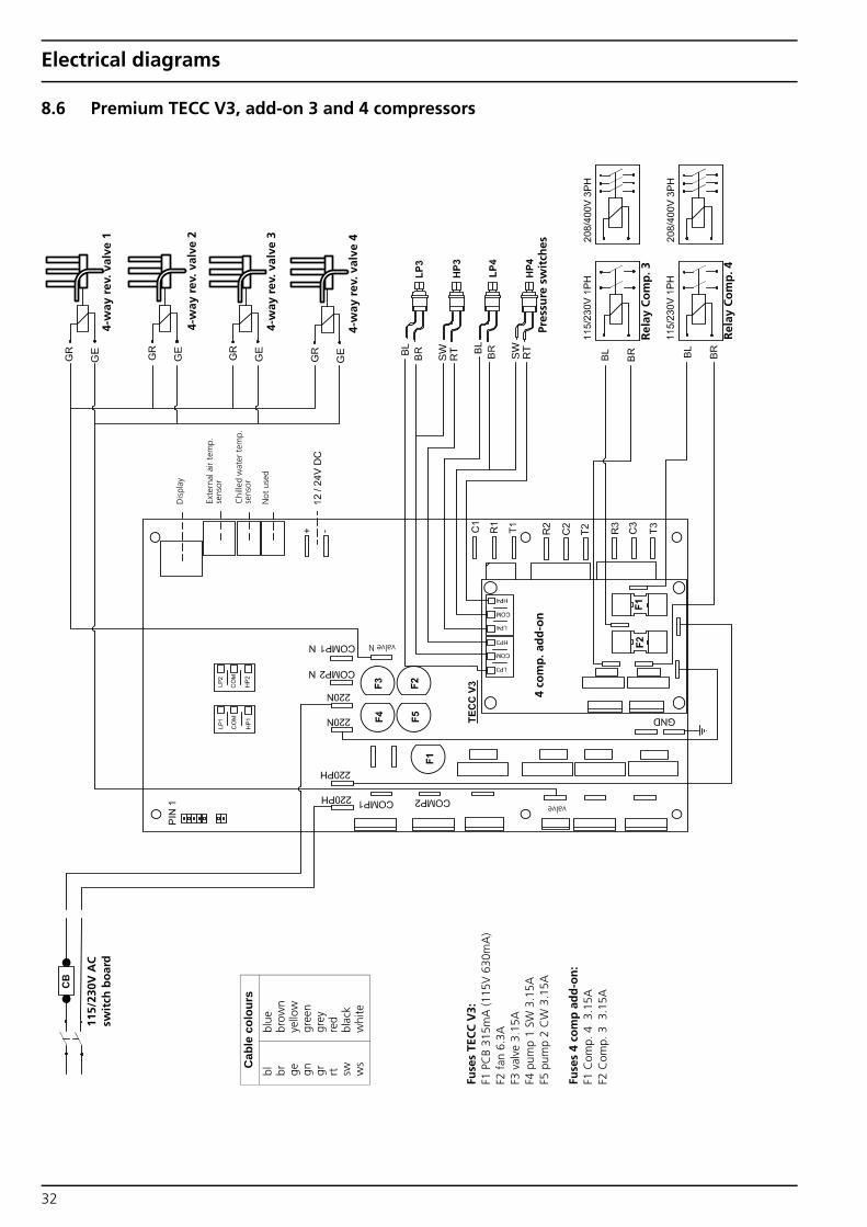
8.6 Premium TECC V3, add-on 3 and 4 compressors
GE
GE
GE
GE RT
SW RT
SW
Fuse
s TE
CC
V3:
F1
PC
B 31
5mA
(115
V 6
30m
A)
F2 f
an 6
.3A
F3
val
ve 3
.15A
F4
pum
p 1
SW 3
.15A
F5
pum
p 2
CW
3.1
5A
Fuse
s 4
com
p a
dd
-on
: F1
Com
p. 4
3.1
5A
F2 C
omp.
3 3
.15A
Cab
le c
olou
rs
bl
br
ge
gn
gr
rt
sw
ws
blue
br
own
yello
w
gree
n gr
ey
red
blac
k w
hite
Rel
ay C
om
p. 3
115/
230V
AC
sw
itch
bo
ard
Pres
sure
sw
itch
es
Dis
play
Exte
rnal
air
tem
p.
sens
or
Chi
lled
wat
er t
emp.
se
nsor
valve
valve N
Not
use
d
4-w
ay r
ev. v
alve
1
Rel
ay C
om
p. 4
4-w
ay r
ev. v
alve
2
4-w
ay r
ev. v
alve
3
4-w
ay r
ev. v
alve
4
4 co
mp
. ad
d-o
n
32

Electrical diagrams
8.7 Premium, compressors
SW
SW
Co
mp
ress
or
115/
230V
1PH
Co
mp
ress
or
115/
230V
1PH
Co
mp
ress
or
208/
400V
3PH
AC
Sw
itch
Boar
d
AC
Sw
itch
Boar
d
TEC
C C
omp
Out
let
Mai
n A
C
TEC
C C
omp
Out
let
Mai
n A
C
TEC
C C
omp
Out
let
Star
t C
apac
itor
Run
Cap
acito
r
Cab
le c
olou
rs
bl
br
sw
blue
br
own
blac
k
33

Electrical diagrams
8.8 Premium TECC V3 with external heater
Fuse
s:
F1 P
CB
315m
A (1
15V
630
mA
) F2
fan
6.3
A
F3 v
alve
3.1
5A
F4 p
ump
1 SW
3.1
5A
F5 p
ump
2 C
W 3
.15A
Cab
le c
olou
rs
bl
br
gr
or
blue
br
own
grey
or
ange
115/
230V
AC
sw
itch
bo
ard
Dis
play
Exte
rnal
air
tem
p.
sens
or
Chi
lled
wat
er t
emp.
se
nsor
fan valve pump2pump1
fan Nvalve N
pum
p1
N
pum
p2
N
Not
use
d
Exte
rnal
hea
ter
con
tro
l
Dan
foss
3-w
ay v
alve
23
0V c
oo
l / e
xt. h
eate
r
IMPO
RTA
NT
For
exte
rnal
hea
ter
oper
atio
n se
t TE
CC
co
ntro
ller
at F
-04,
se
tpoi
nt 1
5°C
2-0
0 an
d 29
°C 9
-03.
34

Electrical diagrams
8.9 Premium TECC V3 with calorifier
SW RT
SW RT
GR GE
GR GE
WS
SW
Fuse
s:
F1 P
CB
315m
A (1
15V
630
mA
) F2
fan
6.3
A
F3 v
alve
3.1
5A
F4 p
ump
1 SW
3.1
5A
F5 p
ump
2 C
W 3
.15A
Cab
le c
olou
rs
bl
br
ge
gn
gr
rt
sw
ws
blue
br
own
yello
w
gree
n gr
ey
red
blac
k w
hite
Rel
ay C
om
p. 1
Blo
wer
AC
sw
itch
bo
ard
Pres
sure
sw
itch
es
Dis
play
Exte
rnal
air
tem
p.
sens
or
Chi
lled
wat
er t
emp.
se
nsor
fan valve pump2
Cap
acito
r an
d re
sist
or p
ump
2 *)
*)In
cas
e a
rela
y is
use
d, t
he c
ontr
olle
r sh
ould
be
with
out
rela
ted
capa
cito
r an
d re
sist
or
Cap
acito
r an
d re
sist
or p
ump
1 *)
pump1
fan Nvalve N
pum
p1
N
pum
p2
N
Not
use
d
4-w
ay r
ev. v
alve
Rel
ay C
om
p. 2
4-w
ay r
ev. v
alve
Seaw
ater
pu
mp
Ch
illed
wat
er p
um
p
**)
IMPO
RTA
NT
In c
ase
a ca
lorif
ier
is u
sed
set
TEC
C
cont
rolle
r at
set
poin
t 15
°C 2
-00
Clix
on /
Ther
mos
tat
H
eate
r el
emen
t
Cal
ori
fier
**)
35
Electrical diagrams
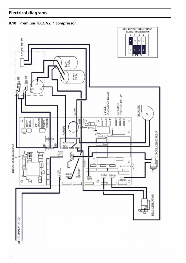
8.10 Premium TECC V2, 1 compressor
36

Electrical diagrams
8.11 Premium TECC V2, add-on 3 and 4 compressors
37

Electrical diagrams
8.12 Premium, MTH mechanical thermostat
SW
115/
230V
AC
Sw
itch
Bo
ard
MTH
Th
erm
ost
at
Blo
wer
Cab
le c
olou
rs
bl
br
gn
sw
blue
br
own
gree
n bl
ack
38
Electrical diagrams
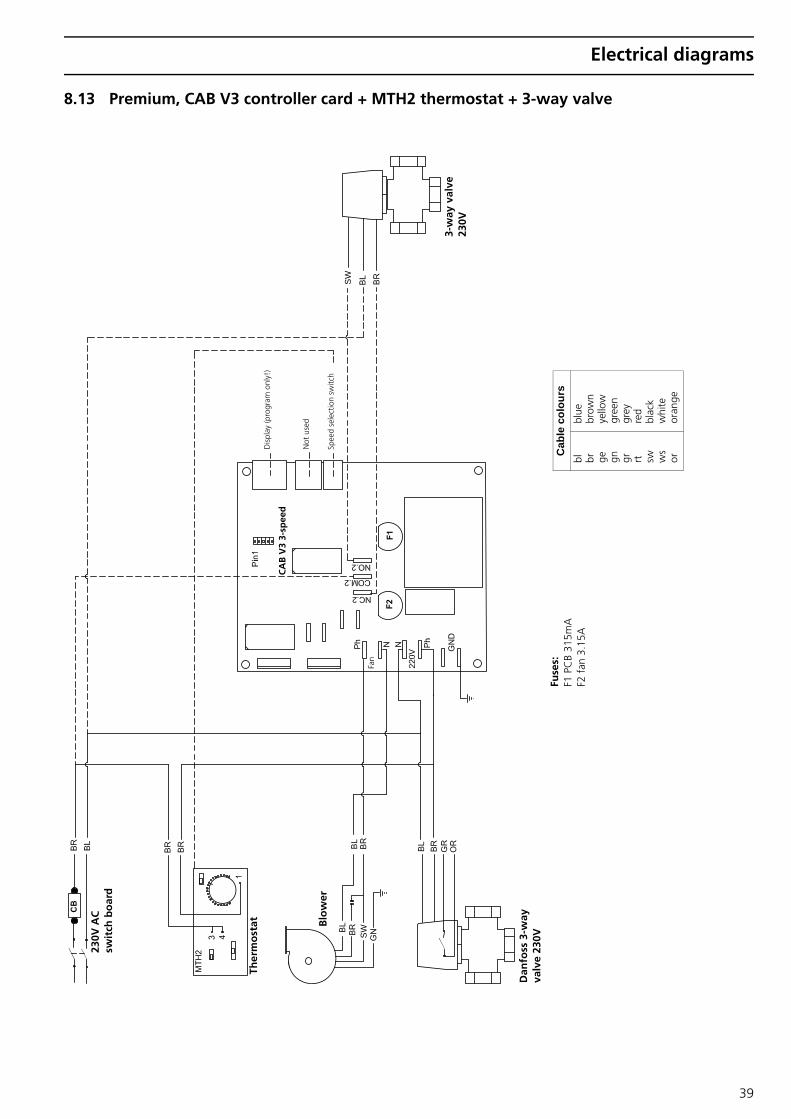
8.13 Premium, CAB V3 controller card + MTH2 thermostat + 3-way valve
SW
SW
Fuse
s:
F1 P
CB
315m
A
F2 f
an 3
.15A
Cab
le c
olou
rs
bl
br
ge
gn
gr
rt
sw
ws
or
blue
br
own
yello
w
gree
n gr
ey
red
blac
k w
hite
or
ange
Blo
wer
230V
AC
sw
itch
bo
ard
Dis
play
(pro
gram
onl
y!)
Not
use
d
Spee
d se
lect
ion
switc
h
CA
B V
3 3-
spee
d
Ther
mo
stat
3-w
ay v
alve
23
0V
Fan
Dan
foss
3-w
ay
valv
e 23
0V
39

Electrical diagrams
8.14 Premium, CAB V3 controller card + Plana thermostat + 3-way valve
SW
SW
Fuse
s:
F1 P
CB
315m
A
F2 f
an 3
.15A
Cab
le c
olou
rs
bl
br
ge
gn
gr
rt
sw
ws
or
blue
br
own
yello
w
gree
n gr
ey
red
blac
k w
hite
or
ange
Blo
wer
230V
AC
sw
itch
bo
ard
Dis
play
(pro
gram
onl
y!)
Not
use
d
Spee
d se
lect
ion
switc
h
CA
B V
3 3-
spee
d
Ther
mo
stat
3-w
ay v
alve
23
0V
Fan
Dan
foss
3-w
ay
valv
e 23
0V
40
Electrical diagrams
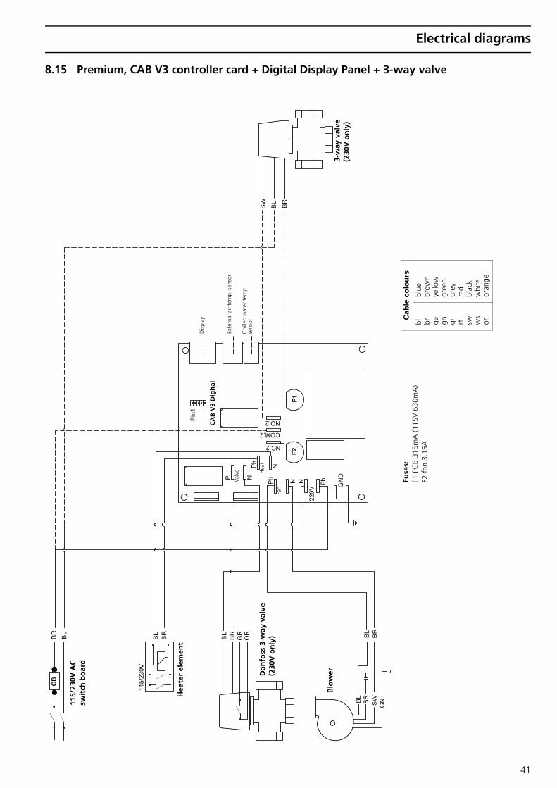
8.15 Premium, CAB V3 controller card + Digital Display Panel + 3-way valve
SW
SW
Fuse
s:
F1 P
CB
315m
A (1
15V
630
mA
) F2
fan
3.1
5A
Cab
le c
olou
rs
bl
br
ge
gn
gr
rt
sw
ws
or
blue
br
own
yello
w
gree
n gr
ey
red
blac
k w
hite
or
ange
Blo
wer
115/
230V
AC
sw
itch
bo
ard
Dis
play
Exte
rnal
air
tem
p. s
enso
r
Chi
lled
wat
er t
emp.
se
nsor
CA
B V
3 D
igit
al
Hea
ter
elem
ent
3-w
ay v
alve
(2
30V
on
ly)
Fan
Dan
foss
3-w
ay v
alve
(2
30V
on
ly)
Valv
e Hea
t
41

Electrical diagrams
8.16 Premium, Silent 5-speed for Compact and Slimline air handlers
Below diagram is OK for index A silent 5-speed controls For an index B you must set code 2 at15 °C to <2 03>
Very important: WBCL000373A can only pilot the A version silencers and are not fowards compatible. WBCL000373B can only pilot the B version silencers and are not backwards compatible.
42
Electrical diagrams
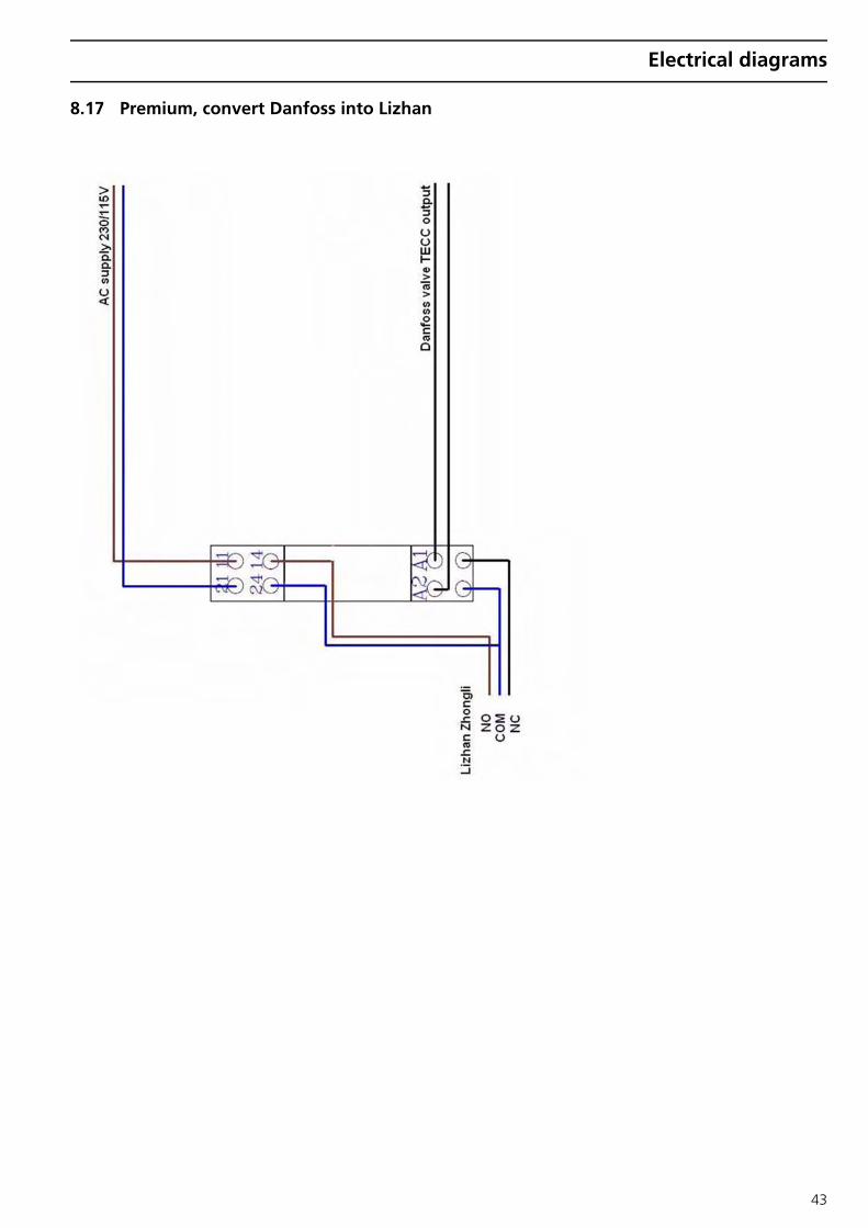
8.17 Premium, convert Danfoss into Lizhan
43

Electrical diagrams
8.18 Fresh-Air units
Fresh-Air V3 wiring
44

Electrical diagrams
45

Electrical diagrams
46

Compressors
9 Compressors
Un
it m
od
el w
ith
Ro
tary
co
mp
ress
or
Co
mp
ress
or
typ
ePa
rt n
um
ber
Each
co
mp
ress
or
Cap
acit
ors
Vo
ltag
eC
able
size
[m
m2 ]
I [A]
Fuse
[A
]R
UN
Part
nu
mb
erST
AR
TPa
rt n
um
ber
Cla
ssic
5
RM54
60H
NE
WBC
L002
260
230V
1Ph
2.5
2.1
820
uF
WBC
L000
180
n/a
n/a
Cla
ssic
5
RM46
0GQ
84W
BCL0
0226
8 11
5V 1
Ph
4.2
1640
uF
WBC
L000
110
n/a
n/a
Cla
ssic
6,5
RM
465G
Q84
WBC
L002
269
115V
1 P
h5.
516
40 u
FW
BCL0
0011
0n/
an/
a
Cla
ssic
7LG
-NK
125P
WBC
L002
261
230V
1Ph
2.5
2.8
1025
uF
WBC
L000
181
n/a
n/a
Cla
ssic
9LG
-NK
164P
WBC
L002
262
230V
1Ph
2.5
3.2
1230
uF
WBC
L000
182
n/a
n/a
Cla
ssic
9LG
-QK
125C
WBC
L002
270
115V
1 P
h6.
520
45 u
FW
BCL0
0010
8n/
an/
a
Cla
ssic
12
LG-N
K18
5PW
BCL0
0226
323
0V 1
Ph2.
54.
416
35 u
FW
BCL0
0010
9n/
an/
a
Cla
ssic
12 /
Prem
ium
12M
ono
- 24
Twin
LG-Q
K16
4CW
BCL0
0227
111
5V 1
Ph
925
50 u
FW
BCL0
0010
7D
ST5/
HS6
00W
BCL0
0000
1
Prem
ium
12M
ono
- 24
Twin
LG-N
K18
5PW
BCL0
0226
323
0V 1
Ph2.
54.
416
35 u
FW
BCL0
0010
9D
ST5/
HS6
00W
BCL0
0000
1
Cla
ssic
16 /
Prem
ium
16M
ono
- 32
Twin
LG-N
J236
PW
BCL0
0226
423
0V 1
Ph2.
55.
620
30 u
FW
BCL0
0018
2D
ST5/
HS6
00W
BCL0
0000
1
Cla
ssic
16 /
Prem
ium
16M
ono
- 32
Twin
LG-Q
K19
1CW
BCL0
0227
211
5V 1
Ph
1132
60 u
FW
BCL0
0018
4D
ST5/
HS6
00W
BCL0
0000
1
Cla
ssic
20 /
Prem
ium
20M
ono
- 40
Twin
- 6
0Tri
LG-N
J282
P W
BCL0
0226
523
0V 1
Ph2.
56.
520
35 u
FW
BCL0
0010
9D
ST5/
HS6
00W
BCL0
0000
1
Cla
ssic
24 /
Pre
miu
m 2
4Mon
o - 5
0Tw
in -
72Tr
i - 1
00Q
trLG
-NP3
62P
WBC
L002
266
230V
1Ph
2.5
7.5
2545
uF
WBC
L000
108
DST
5/H
S600
WBC
L000
001
Cla
ssic
30 /
Pre
miu
m 3
0Mon
o - 6
0Tw
in -
90Tr
i - 1
20Q
trLG
-NP4
07P
WBC
L002
267
230V
1Ph
49
2555
uF
WBC
L000
183
DST
5/H
S600
WBC
L000
001
47

Compressors
Un
it m
od
el w
ith
Scr
oll
com
pre
sso
rC
om
pre
sso
r ty
pe
Part
nu
mb
erEa
ch c
om
pre
sso
rC
apac
ito
rs
Vo
ltag
eC
able
siz
e[m
m2 ]
I [A
]Fu
se[A
]R
UN
Part
nu
mb
erST
AR
TPa
rt n
um
ber
Prem
ium
30M
ono
- 60
Twin
LG
-HQ
028
PW
BCL0
0950
423
0V 1
Ph4
60 u
FW
BCL0
0950
2D
ST5/
HS6
00W
BCL0
0000
1
Prem
ium
30M
ono
- 60
Twin
- 9
0Tri
- 12
0Qtr
Cop
elan
d-ZR
28W
BCL0
0939
923
0V 1
Ph4
1032
45 u
FW
BCL0
0010
8D
ST5/
HS6
00W
BCL0
0000
1
Prem
ium
36M
ono
- 72
Twin
- 1
08Tr
iLG
-HQ
034
PW
BCL0
0948
723
0V 1
Ph4
60 u
FW
BCL0
0950
2D
ST6
WBC
L000
027
Prem
ium
36M
ono
- 72
Twin
- 1
08Tr
i - 1
44Q
trC
opel
and-
ZR34
WBC
L009
397
230V
1Ph
411
.532
50 u
FW
BCL0
0010
7D
ST6
WBC
L000
027
Prem
ium
42M
ono
- 84
Twin
- 1
26Tr
iLG
-HQ
040
PW
BCL0
0948
823
0V 1
Ph4
60 u
FW
BCL0
0950
2D
ST6
WBC
L000
027
Prem
ium
42M
ono
- 84
Twin
- 1
26Tr
i - 1
68Q
trC
opel
and-
ZR40
WBC
L009
396
230V
1Ph
413
.540
55 u
FW
BCL0
0018
3D
ST6
WBC
L000
027
Prem
ium
48M
ono
- 96
Twin
- 1
44Tr
iLG
-HR
049P
WBC
L009
489
230V
1Ph
460
uF
WBC
L009
502
DST
6W
BCL0
0002
7
Prem
ium
48M
ono
- 96
Twin
- 1
44Tr
i - 1
92Q
trC
opel
and-
ZR48
WBC
L009
401
230V
1Ph
415
4060
uF
WBC
L000
184
DST
6W
BCL0
0002
7
Prem
ium
30M
ono
- 60
Twin
LG
-HQ
028
YW
BCL0
0949
240
0V 3
Ph4
Prem
ium
36M
ono
- 72
Twin
- 1
08Tr
iLG
-HQ
034
YW
BCL0
0949
440
0V 3
Ph4
Prem
ium
42M
ono
- 84
Twin
- 1
26Tr
iLG
-HQ
040
YW
BCL0
0949
640
0V 3
Ph4
Prem
ium
48M
ono
- 96
Twin
- 1
44Tr
iLG
-HR
049Y
WBC
L009
498
400V
3Ph
4
Prem
ium
60M
ono
- 18
0Tri
- 24
0Qtr
LG-H
R 06
1YW
BCL0
0228
340
0V 3
Ph4
Prem
ium
216
Tri -
288Q
trLG
-HR
073Y
WBC
L009
499
400V
3Ph
4
Prem
ium
252
Tri -
336Q
trLG
-HR
081Y
WBC
L009
500
400V
3Ph
4
Prem
ium
384
Qtr
Cop
elan
d-ZR
90K
3EW
BCL0
0938
640
0V 3
Ph4
Cop
elan
d-ZR
94K
CE
WBC
L009
386B
400V
3Ph
4
Prem
ium
448
Qtr
Cop
elan
d-ZR
11M
3EW
BCL0
0938
940
0V 3
Ph4
Cop
elan
d-ZR
108M
3EW
BCL0
0938
9B40
0V 3
Ph4
Prem
ium
504
Qtr
Cop
elan
d-ZR
12M
3EW
BCL0
0938
740
0V 3
Ph4
???
WBC
L009
387B
400V
3Ph
4
Prem
ium
572
Qtr
Cop
elan
d-ZR
16M
3EW
BCL0
0938
840
0V 3
Ph4
Cop
elan
d-ZR
144K
CE
WBC
L009
388B
400V
3Ph
4
48

Blowers
49
10 Blowers
Including capacitor, insulated
Blo
wer
s 23
0V
Part
nu
mb
er
Cap
acit
or
Part
nu
mb
erU
nit
mo
del
I [A]
Fuse
[A]
Ecof
it 2G
RE15
120
x62R
WBC
L007
020
2 uF
WBC
L000
017
CPA
C5/
7-C
ompa
ct 4
500/
6000
0.35
2
Ecof
it 2G
RE25
140
x59R
W
BCL0
0702
12.
5 uF
WBC
L000
009
CPA
C9-
Com
pact
900
00.
573
Ecof
it 2G
RE35
140
x59R
WBC
L007
022
4 uF
WBC
L000
018
CPA
C12
/24-
Com
pact
120
00/2
4000
0.65
3
Ecof
it 2G
RE45
180
x75R
WBC
L007
023
6 uF
WBC
L000
070
CPA
C16
/20-
Com
pact
160
00/2
0000
0.87
4
Ecof
it 2G
RE45
160
x62R
WBC
L007
025
6 uF
WBC
L000
070
CPA
C30
-Com
pact
300
00-F
resh
Air2
40.
854
Ecof
it 2G
RE65
180
x70R
WBC
L007
024
12 u
FW
BCL0
0704
1Fr
esh-
Air4
8-Sp
ecia
l24
1.25
6
Blo
wer
s 11
5V
Part
nu
mb
erC
apac
ito
rPa
rtn
um
ber
Un
it m
od
elI [A]
Fuse
[A]
Ecof
it 2G
RE15
120
x62R
WBC
L007
030
6 uF
WBC
L000
070
CPA
C5/
6.5-
Com
pact
450
0/60
000.
73
Ecof
it 2G
RE25
140
x59R
W
BCL0
0703
18
uFW
BCL0
0000
8C
PAC
9-C
ompa
ct 9
000
1.15
6
Ecof
it 2G
RE35
140
x59R
WBC
L007
032
18 u
FW
BCL0
0001
2C
PAC
12/2
4-C
ompa
ct 1
2000
/240
001.
36
Ecof
it 2G
RE45
180
x75R
WBC
L007
033
24 u
FW
BCL0
0001
6C
PAC
16/2
0-C
ompa
ct 1
6000
/200
001.
758

BlueCool Unit Performance Report
11 BlueCool Unit Performance Report
Unit type : .................... Serial number : .................... Refrigerant : R22 / R407
Check before unit start-up: T ambient compressor : .................... °C P discharge circuit I / II : .................... / .................... bar T ambient outside : .................... °C
Check running in Cool cycle: Circuit I Circuit II
U Compressor : .................... .................... Volts I Compressor : .................... .................... Amps Frequency : .................... .................... Hz
1. T seawater inlet : .................... .................... °C 2. T seawater outlet : .................... .................... °C 3. Volume seawater : .................... ltr/min. (at unit or through-hull)
Height seawater outlet : .................... m (above water level) Inside diameter suction line : .................... mm Inside diam. outlet through-hull : .................... mm Height seawater inlet : .................... m below water level Inside diameter discharge line : .................... mm Inside diam. inlet through-hull : .................... mm Pump total discharge head : .................... m
Type / size strainer : ............................................................ Number of strainers : .................... pieces Max.Strainer flow-rate : .................... ltr/min each
4. T condenser inlet : .................... .................... °C 5. T condenser outlet : .................... .................... °C
6. T liquid : .................... .................... °C
7. T evaporator inlet : .................... .................... °C 8. T evaporator outlet : .................... .................... °C
9. T suction : .................... .................... °C 9a. T bulb expansion valve : .................... .................... °C 10. P suction : .................... .................... bar
11. T discharge : .................... .................... °C 12. P discharge : .................... .................... bar
13. T chilled water inlet : .................... .................... °C 14. T chilled water outlet : .................... .................... °C
Air handler(s) (Fan coil) I II III IV 15. T blower air inlet : ............... °C ............... °C ............... °C ............... °C 16. T blower air outlet : ............... °C ............... °C ............... °C ............... °C 17. T water air handler inlet : ............... °C ............... °C ............... °C ............... °C 18. T water air handler outlet : ............... °C ............... °C ............... °C ............... °C
Gau
ging
site
in
dra
win
g
Report date : ....................
50

BlueCool Unit Performance Report
Check running in Heat cycle: Circuit I Circuit II
U Compressor : .................... .................... Volts I Compressor : .................... .................... Amps Frequency : .................... .................... Hz
1. T seawater inlet : .................... .................... °C 2. T seawater outlet : .................... .................... °C 3. Volume seawater : .................... ltr/min. (at unit or through-hull)
Height seawater outlet : .................... m (above water level) Inside diameter suction line : .................... mm Inside diam. outlet through-hull : .................... mm Height seawater inlet : .................... m below water level Inside diameter discharge line : .................... mm Inside diam. inlet through-hull : .................... mm Pump total discharge head : .................... m
Type / size strainer : ............................................................ Number of strainers : .................... pieces Max.Strainer flow-rate : .................... ltr/min each
4. T condenser inlet : .................... .................... °C 5. T condenser outlet : .................... .................... °C
6. T liquid : .................... .................... °C
7. T evaporator inlet : .................... .................... °C 8. T evaporator outlet : .................... .................... °C
9. T suction : .................... .................... °C 9a. T bulb expansion valve : .................... .................... °C 10. P suction : .................... .................... bar
11. T discharge : .................... .................... °C 12. P discharge : .................... .................... bar
13. T chilled water inlet : .................... .................... °C 14. T chilled water outlet : .................... .................... °C
Air handler(s) (Fan coil) I II III IV 15. T blower air inlet : ............... °C ............... °C ............... °C ............... °C 16. T blower air outlet : ............... °C ............... °C ............... °C ............... °C 17. T water air handler inlet : ............... °C ............... °C ............... °C ............... °C 18. T water air handler outlet : ............... °C ............... °C ............... °C ............... °C
Conclusion: ........................................................................................................................................................................................................................................................................................................................................................................................................................................................................................................................................................................................................................................................................................................................................................................................................................................................................................................................................................................................................................................................................................................................................................................................................................................................................................................................................................................................................................................................................................................................................................................................................................................................................................................................................................................................................................................................................................................................................................................................................................................................................................................................................................................................................................................................................................................................
Gau
ging
site
in
dra
win
g
51

BlueCool Unit Performance Report
Controller settings
Main menu Function Description AC AH 1 AH 2 AH 3 AH 4
.. Room temperature
.. Setpoint temperature
b.. Fan speed
H / E.. Temperature
F.. Cycle mode
U.. Line current
1C.. Compressor 1 on/off
2C.. Compressor 2 on/off
3C.. Compressor 3 on/off
4C.. Compressor 4 on/off
P.. Compressor sequence
L.. Start delay compressors
1L.. Temp. comp. 1 off
2L.. Temp. comp. 2 off
3L.. Temp. comp. 3 off
4L.. Temp. comp. 4 off
d… Dehumidifying
t… Display time
29 °C menu 0 Temp. low cut-out
1 Temp. low cut-in
2 Temp. high cut-out
3 Temp. high cut-in
4 Calibration H/E temp. sensor
5 Time [min] to sleep mode
6 Start delay unit
7 Calibration room temp sensor
8 Calibration AC 50 Hz
9 Setting R2
A Calibration AC 60 Hz
b Software version
c Pump 1 continuous/staged
d Lower VDC pump 1
E Higher VDC pump 1
F –
15 °C menu 0 Low AC voltage cut-out
1 Remote control
2 Setting R1/Blower type
3 Blower setting
4 Internal / external room temp. sensor
5 Fahrenheit or Celsius
6 Setting fanspeed level 5
7 Setting fanspeed level 4
8 Setting fanspeed level 3
9 Setting fanspeed level 2
A Setting fanspeed level 1
b Set security CODE
c Dehumidifying time heating
d Dehumidifying time cooling
52
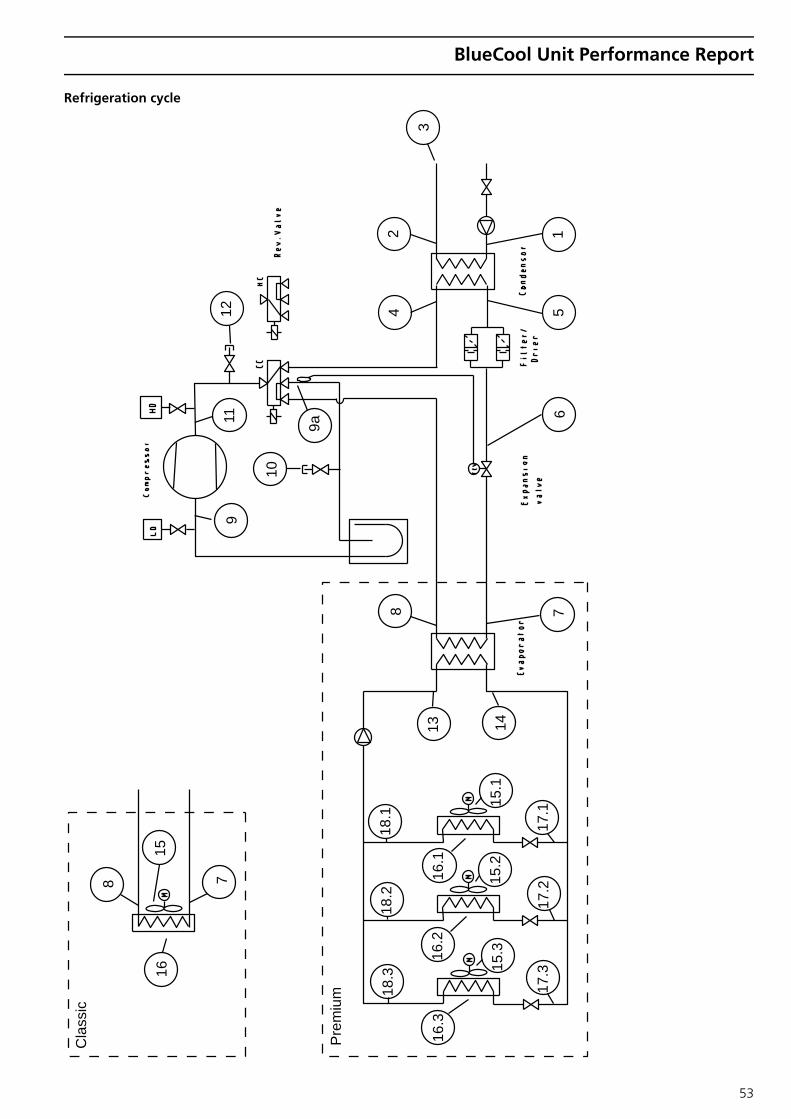
BlueCool Unit Performance Report
Refrigeration cycle
3
24
15
67
14
17.1
17.2
17.3
15.2
15.3
15.1
16.1
16.2
16.3
18.3
18.2
18.1
13
8
7
Cla
ssic
Pre
miu
m
15
8
16
9
10
12
9a11
53
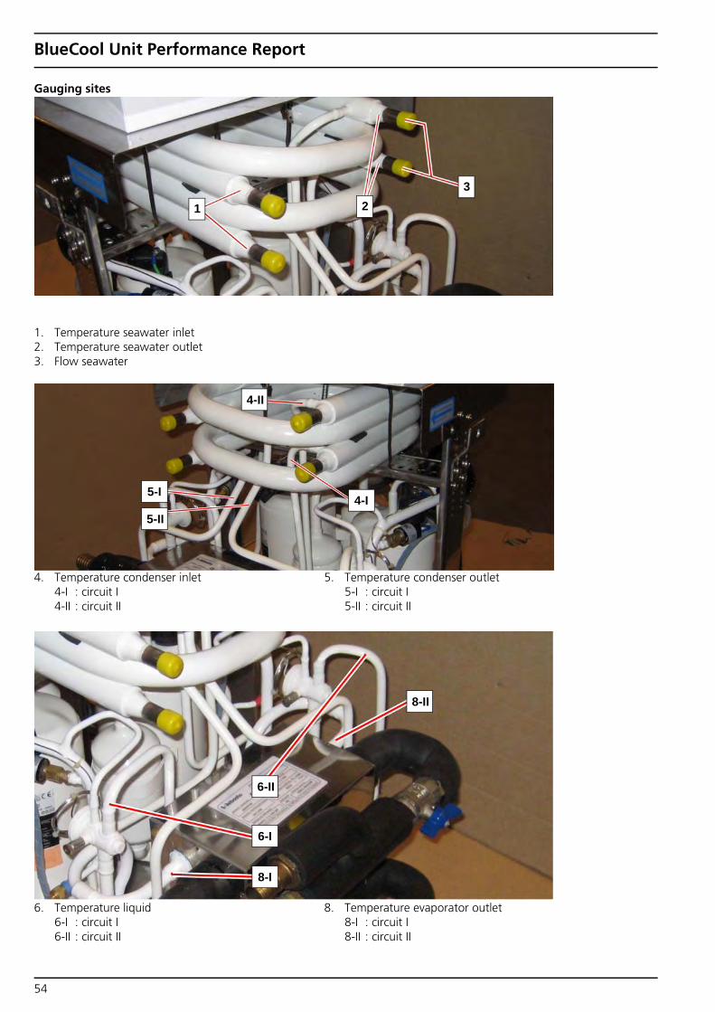
BlueCool Unit Performance Report
Gauging sites
1. Temperature seawater inlet 2. Temperature seawater outlet 3. Flow seawater
1 23
4-I
4-II
5-II
5-I
4. Temperature condenser inlet 4-I : circuit I 4-II : circuit II
5. Temperature condenser outlet 5-I : circuit I 5-II : circuit II
8-II
6. Temperature liquid 6-I : circuit I 6-II : circuit II
8. Temperature evaporator outlet 8-I : circuit I 8-II : circuit II
6-II
6-I
8-I
54

BlueCool Unit Performance Report
For proper measurement of temperature at point 13 and 14, the tubular insulation has to be removed or pushed aside.
6
8
10
147
9a
12
6. Temperature liquid circuit II 7. Temperature evaporator inlet circuit II 8. Temperature evaporator outlet circuit II 9a. Temperature bulb expansion valve circuit II
10. Pressure suction circuit II 12. Pressure discharge circuit II 14. Temperature chilled water outlet circuit II
9
11
9a
12
9. Temperature suction circuit I 9a. Temperature bulb expansion valve circuit I 11. Temperature discharge circuit I
8-I. Temperature evaporator outlet circuit I
13-I. Temperature chilled water inlet circuit I
13-II. Temperature chilled water inlet circuit II
14-I. Temperature chilled water outlet circuit I
14-I
9a
8-I
13-I
13-II
55

ent-
No.
xxx
xxxx
A •
11/
10 •
Err
ors
and
omis
sion
s ex
cept
ed •
Prin
ted
in T
he N
ethe
rland
s •
© W
ebas
to A
G, G
CS
2010
Webasto Product International NL Constructieweg 47NL - 8263 BC KampenThe NetherlandsPhone: +31 (0) 38 337 11 37 Fax: +31 (0) 38 332 51 81 E-mail: [email protected] Internet: http://www.webasto.com
Idhttp://dealers.webasto.com