TROUBLE SHOOTING AND PARTS REPLACEMENT...
17
Y1-03-0266 Rev. A Page | 1 TROUBLE SHOOTING AND PARTS REPLACEMENT MANUAL FOR THE REMOTE CONTROLLED SEARCH LIGHT, RCL-100
Transcript of TROUBLE SHOOTING AND PARTS REPLACEMENT...

Y1-03-0266 Rev. A Page | 1
TROUBLE SHOOTING AND PARTS REPLACEMENT MANUAL
FOR THE REMOTE CONTROLLED SEARCH LIGHT, RCL-100

Y1-03-0266 Rev. A Page | 2
INDEX
Troubleshooting tools needed 3
Wiring guide 3
Pointpad / Master controller compatibility 5
12V / 24V 5
Searchlight and Wiring Diagram 6
Breakdown procedure 7, 8
Slip ring and Planet gear assembly 9
Rotation motor assembly 10
Troubleshooting the light 12 – 13
Repair / Refurbishment of searchlights 14
Recommended maintenance. 15
Parts List 16

Y1-03-0266 Rev. A Page | 3
Troubleshooting tools needed. Ohm Meter Rubbing Alcohol Wire Brush
Clean Rags #2 Phillips Screwdriver Length of wires (2) with crocodile clips on each end to connect to battery. 12V Battery or Power Supply (3.5Amp capability)
Wiring Guide.
YELLOW Lamp power
GREEN Lamp power
RED Elevation motor
WHITE Elevation motor
BLACK Rotation motor
BROWN Rotation motor

Y1-03-0266 Rev. A Page | 4
System Wiring Schematic.
Master
RCL-100
Point Pad
Spotlight
Yellow Lamp Power
Green Lamp Ground
Red Spot Up
White Spot Down
Brown Spot Left
Black Spot Right
Other RCL-100 Point Pads
75 ohm TV Coaxial Cable
75 ohm TV Coaxial Cable
“T” Connector or Optional
75 Ohm Splitter for Multiple
RCL-100 Point Pads
Ground
Blue Orange
Note: Wiring must be in accordance with this diagram. Improper wiring will damage components.
12 VDC or
24 VDC
Master Controller
in-line 15 amp fuse
Power Source Fuse

Y1-03-0266 Rev. A Page | 5
Compatibility of POINTPAD URP with MASTER CONTROLLER URC
There are 3 generations of control systems for the RCL 100 searchlight.
Model numbers 100, 101 and 102. If there is a ‘yes’ behind the combination, they can be
connected together and will function properly, if the individual modules are in working
condition.
URP 100 - URC 100/101 - yes
URP 101 - URC 100/ 101 - yes
URP 102 - URC 101 - yes
URC 102 - URP 101 - yes
URP 100 - URC 102 - no
URP 102 - URC 100 - no
12V / 24V Lights.
The difference between a 12V light and a 24V light is ONLY the rating of the bulb. If one wants
to convert the light from one voltage to another, the bulbs need to be replaced.
12V Part Number 6001
24V Part Number 6003

Y1-03-0266 Rev. A Page | 6

Y1-03-0266 Rev. A Page | 7
To remove the head from the base, loosen the 4 screws from the collar and carefully lift the
head off the base.

Y1-03-0266 Rev. A Page | 8
To remove the complete Front Frame assembly from the head of the light, remove the front
frame and glass assembly. Loosen the two lock nuts from the hex studs and turn out the two
studs sufficiently to slide the assembly out.
Pull the Front Frame assembly out of the searchlight.

Y1-03-0266 Rev. A Page | 9
Complete Reflector/elevation motor assembly.

Y1-03-0266 Rev. A Page | 10
Typical view of a good and clean slip ring that transfers the voltage from the copper tracks to
the contacts mounted in the head of the light.
RED/WHITE UP AND DOWN
GREEN/YELLOW RIGHT AND LEFT
View of the two plastic gears, driven by the Rotation motor, and the contact assembly that
transfer the voltage from the slip ring to the bulbs and elevation motor.
3 - RED
1 - WHITE 2 - GREEN
4 - YELLOW
Planet Gear
Contact assembly

Y1-03-0266 Rev. A Page | 11
Rotation motor. It is actually an assembly that consists of a motor and a gearbox with
spindle gear.
GEARBOX
MOTOR

Y1-03-0266 Rev. A Page | 12
TROUBLESHOOTING
Testing the
system with
all
connected.
Use a volt/ohm meter set to DC Voltage. Measure from ground to each color wire,
of the MCU (Master Controller) going out to the light. The voltage should read
between 8 to 10 Volts DC, when the point pad is activated. If, for example, you
want to check the elevation, measure on the RED and WHITE when the Point pad
is pressed to ‘down’. There should be 8-10 V on one of these wires.
Motion is OK,
but no light
Disconnect the YELLOW and GREEN wires (in the 6-wire wiring harness leading
out of the Master Controller) and connect the 12V battery test wires to the yellow
and green wires LEADING TO THE LIGHT. If the lamps do not light up, check
the continuity of the yellow and green wires and any splices or terminal
connections through the harness to the searchlight. If the continuity tests OK, the
bulbs must be checked. Do the following:
Please do not try to test the bulbs with a tester/ohm meter as you would a normal
incandescent house bulb. Remove (without touching the bulb with your hand) the
bulb from the socket and connect the leads to a 6V battery to test them. If the
bulbs test good, check for corrosion on the brush assembly mounted at the bottom
of the housing, or on the slip ring assembly mounted in the base.
If there is corrosion on either the brush or slip ring assemblies, gently clean it off
with a fine wire brush or sanding paper and wipe clean with rubbing alcohol. If
the slip ring assembly is pitted, it will need to be replaced.
If the brush and slip ring are OK, and the lamps light up when connected to the
battery, the MCU (Master control unit) needs to be replaced.

Y1-03-0266 Rev. A Page | 13
No up and
down,
everything
else is OK
Disconnect the RED and WHITE wires (in the 6-wire wiring harness leading out of
the Master Controller) and connect the 12V battery test wires to the red and
white wires LEADING TO THE LIGHT. The light should move either up or down.
If you change the POLARITY it should move the other way. If this happens without
a problem, the MCU (Master control unit) is faulty and needs to be replaced. If
not, do the following:
Remove the four screws underneath the head of the light, to loosen the protection
cover. Gently lift the head from the base in order to view the brush and slip ring
assembly. If any corrosion is evident, gently clean the brush and slip ring
assemblies with a fine wire brush, taking care to wipe clean with a rag and
rubbing alcohol. If pitting has occurred on the slip ring, or if the brush assembly
is damaged, the unit must be sent in for repair. The service agent or owner can
replace the parts by ordering new ones. If these parts look OK, connect the leads
from the battery to both of the small pins on the brush assembly. The elevation
motor should turn. If you reverse the wires the motor should turn in the opposite
direction. If the motor does not turn with this test, then the elevation motor needs
to be replaced.
No left and
right,
everything
else is OK
Disconnect the BLACK and BROWN wires (in the 6-wire wiring harness leading
out of the Master Controller) and connect the 12V battery test wires to the black
and brown wires LEADING TO THE LIGHT. The light should move either left or
right. If you change the POLARITY it should move the other way. If this happens
without a problem, the MCU (Master control unit) is faulty and needs to be
replaced.
If not, do the following:
Remove the four screws underneath the head of the light, to loosen the protection
cover. Gently lift the head from the base in order to view the two plastic gears by
turning the head upside down to see them. If they are intact, the ROTATION
motor is faulty. Replace this motor.
If the planet gears are stripped, order new and install.
Y1-03-0266 Rev. A Page | 14
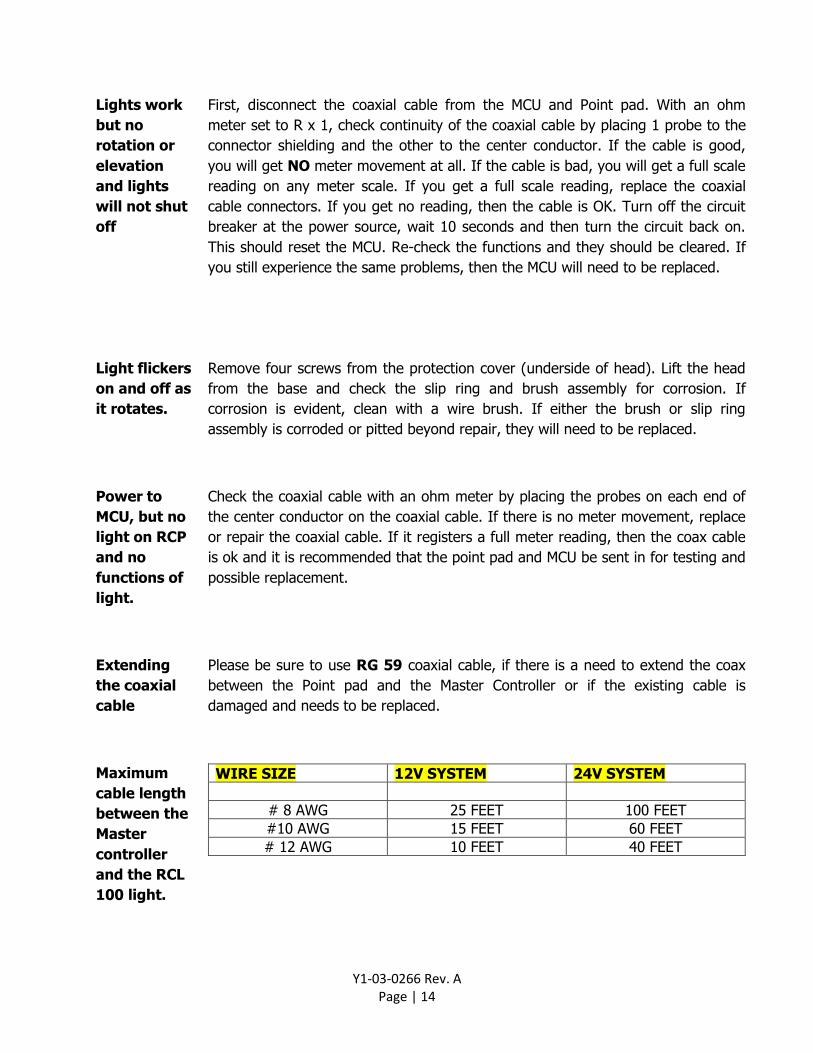
Lights work
but no
rotation or
elevation
and lights
will not shut
off
First, disconnect the coaxial cable from the MCU and Point pad. With an ohm
meter set to R x 1, check continuity of the coaxial cable by placing 1 probe to the
connector shielding and the other to the center conductor. If the cable is good,
you will get NO meter movement at all. If the cable is bad, you will get a full scale
reading on any meter scale. If you get a full scale reading, replace the coaxial
cable connectors. If you get no reading, then the cable is OK. Turn off the circuit
breaker at the power source, wait 10 seconds and then turn the circuit back on.
This should reset the MCU. Re-check the functions and they should be cleared. If
you still experience the same problems, then the MCU will need to be replaced.
Light flickers
on and off as
it rotates.
Remove four screws from the protection cover (underside of head). Lift the head
from the base and check the slip ring and brush assembly for corrosion. If
corrosion is evident, clean with a wire brush. If either the brush or slip ring
assembly is corroded or pitted beyond repair, they will need to be replaced.
Power to
MCU, but no
light on RCP
and no
functions of
light.
Check the coaxial cable with an ohm meter by placing the probes on each end of
the center conductor on the coaxial cable. If there is no meter movement, replace
or repair the coaxial cable. If it registers a full meter reading, then the coax cable
is ok and it is recommended that the point pad and MCU be sent in for testing and
possible replacement.
Extending
the coaxial
cable
Please be sure to use RG 59 coaxial cable, if there is a need to extend the coax
between the Point pad and the Master Controller or if the existing cable is
damaged and needs to be replaced.
Maximum
cable length
between the
Master
controller
and the RCL
100 light.
WIRE SIZE 12V SYSTEM 24V SYSTEM
# 8 AWG 25 FEET 100 FEET
#10 AWG 15 FEET 60 FEET
# 12 AWG 10 FEET 40 FEET

Y1-03-0266 Rev. A Page | 15
Need to send
the light to
ACR for
repair?
Please send the light to: Technical Service, ACR Electronics Inc. 5757 Ravenswood road Fort Lauderdale, Fl 33312 Please add a memo with the sender/company name, full return address and contact number of a person that can OK a quote on the service/repair of the above.
Need to send
the light to
ACR for
complete
refurbish-
ment?
Please send the light to: Technical Service, ACR Electronics Inc. 5757 Ravenswood road Fort Lauderdale, Fl 33312 Please add a memo with what needs to be done (refurbishment), sender/company name, full return address and contact number of a person that can OK a quote on the complete refurbishment of the light.

Y1-03-0266 Rev. A Page | 16
Recommended Maintenance As with any marine product, proper care and regular maintenance is highly recommended. In order to help prevent premature failure of your ACR searchlight the following steps are recommended: The best preventative maintenance one can do is to ensure that the best possible care is taken when installing the light. The biggest problem on these lights is water intrusion from the way it is mounted, if not done well. During the lifetime of the light, a regular, very close inspection must be made of the paint around the base of the unit. ANY sign of lifting, flaking or 'bubbling' of the paint around the base is a sign of water intrusion. Any sign of humidity on the inside of the glass lens of the light is trouble. The best time to inspect the light is early in the morning. During the day the light is heated by the sun, all air is pushed out, at night the humid air is pulled in and the moisture builds up. • Always try to keep the light surface clean. Build up of salt, dirt or paint cause corrosion. • Periodically (recommend monthly) rotate and elevate your light to help extend operational life
of the motors. The URC-102 Master Controller has a built in XRCiZ feature. When this feature is enabled, the Master Controller will automatically rotate and elevate the searchlight once a month.
• Normal temperature fluctuations can cause condensation (condensation is any moisture on
inside of glass) to form inside body of the light. If condensation is observed, remove the front frame and allow unit to dry.
• Whenever disassembling the searchlight, use anti-seize compound (such as Tef-gel™) on
bolts and hardware. Rejuvenate gaskets with silicon grease and replace worn or missing phenolic and/or nylon shoulder washers.
• Forceful Manual turning of the light is discouraged due to the possibility of damage to internal
components. • Silicon grease can be used to rejuvenate all gasket material. • Replace worn or missing phenolic and/or nylon shoulder washers. • If the base of the light is removed for any reason, be sure to re-install using nylon shoulder
washers in the bolt holes to help prevent the natural reaction of dissimilar metals (aluminum & stainless steel).
Y1-03-0266 Rev. A Page | 17
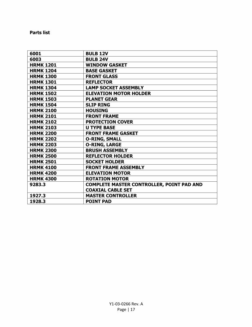
Parts list
6001 BULB 12V
6003 BULB 24V
HRMK 1201 WINDOW GASKET
HRMK 1204 BASE GASKET
HRMK 1300 FRONT GLASS
HRMK 1301 REFLECTOR
HRMK 1304 LAMP SOCKET ASSEMBLY
HRMK 1502 ELEVATION MOTOR HOLDER
HRMK 1503 PLANET GEAR
HRMK 1504 SLIP RING
HRMK 2100 HOUSING
HRMK 2101 FRONT FRAME
HRMK 2102 PROTECTION COVER
HRMK 2103 U TYPE BASE
HRMK 2200 FRONT FRAME GASKET
HRMK 2202 O-RING, SMALL
HRMK 2203 O-RING, LARGE
HRMK 2300 BRUSH ASSEMBLY
HRMK 2500 REFLECTOR HOLDER
HRMK 2501 SOCKET HOLDER
HRMK 4100 FRONT FRAME ASSEMBLY
HRMK 4200 ELEVATION MOTOR
HRMK 4300 ROTATION MOTOR
9283.3 COMPLETE MASTER CONTROLLER, POINT PAD AND COAXIAL CABLE SET
1927.3 MASTER CONTROLLER
1928.3 POINT PAD