TRK-101-P Installation Manual - Flir.com · 2 TRK-101-P Installation Manual March 22, 2017 A...
43
Ver. 2 March 22, 2017 IOI SD Installation Manual TRK-101-P PTZ Tracker
Transcript of TRK-101-P Installation Manual - Flir.com · 2 TRK-101-P Installation Manual March 22, 2017 A...

Ver. 2 March 22, 2017
IOI SD
Installation Manual TRK-101-P PTZ Tracker
ii TRK-101-P Installation Manual March 22, 2017
© 2017 FLIR Systems, Inc. All rights reserved worldwide. No parts of this manual, in whole or in part, may be copied, photocopied, translated, or transmitted to any electronic medium or machine readable form without the prior written permission of FLIR Systems, Inc. Names and marks appearing on the products herein are either registered trademarks or trademarks of FLIR Systems, Inc. and/or its subsidiaries. All other trademarks, trade names, or company names referenced herein are used for identification only and are the property of their respective owners. This product is protected by patents, design patents, patents pending, or design patents pending. The contents of this document are subject to change. FLIR Systems, Inc. 6769 Hollister Avenue Goleta, CA 93117 Phone: 888.747.FLIR (888.747.3547) International: +1.805.964.9797 For technical assistance, please call us at +1.888.388.3577 or visit the Service & Support page at www.flir.com/security. Important Instructions and Notices to the User: Modification of this device without the express authorization of FLIR Commercial Systems, Inc. may void the user’s authority under FCC rules to operate this device. .
March 22, 2017 TRK-101-P Installation Manual iii
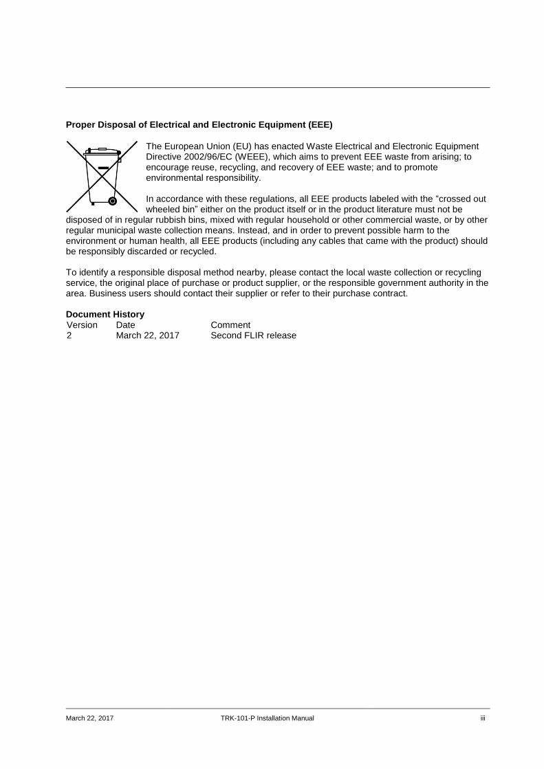
Proper Disposal of Electrical and Electronic Equipment (EEE)
The European Union (EU) has enacted Waste Electrical and Electronic Equipment Directive 2002/96/EC (WEEE), which aims to prevent EEE waste from arising; to encourage reuse, recycling, and recovery of EEE waste; and to promote environmental responsibility. In accordance with these regulations, all EEE products labeled with the “crossed out wheeled bin” either on the product itself or in the product literature must not be
disposed of in regular rubbish bins, mixed with regular household or other commercial waste, or by other regular municipal waste collection means. Instead, and in order to prevent possible harm to the environment or human health, all EEE products (including any cables that came with the product) should be responsibly discarded or recycled. To identify a responsible disposal method nearby, please contact the local waste collection or recycling service, the original place of purchase or product supplier, or the responsible government authority in the area. Business users should contact their supplier or refer to their purchase contract. Document History Version Date Comment 2 March 22, 2017 Second FLIR release

iv TRK-101-P Installation Manual March 22, 2017

Table of Contents
March 22, 2017 TRK-101-P Installation Manual v
Table of Contents Document Scope and Purpose .............................................................................................. 1
Introduction .............................................................................................................................. 9
2.1 Package Contents ........................................................................................................ 10
Hardware Description ........................................................................................................... 11
3.1 Power Connection Panel .............................................................................................. 11
3.1.1 Video Connection Panel ........................................................................................... 13
System Requirements ........................................................................................................... 15
Installing and Connecting the Unit ...................................................................................... 17
5.1 Installing the Unit .......................................................................................................... 17
5.1.1 Assembling the Unit in a Rack Mount Panel (Optional Accessory) ......................... 18
5.2 Connecting the Unit ...................................................................................................... 19
5.2.1 Grounding the Unit ................................................................................................... 19
5.2.2 Connecting the Unit to the Power Supply ................................................................ 19
5.2.3 Using the DNA Utility to Connect the Unit to the Network........................................ 20
5.2.4 Connecting the Video Source (Camera) to the Unit ................................................. 23
5.2.5 Configuring PTZ Camera Settings on the Encoder .................................................. 24
5.2.6 Connecting the Analog Video Output to an Analog Device ..................................... 26
5.2.7 Connecting the Unit to Receive Alarms from External Devices (Alarm Inputs) ...... 26
5.2.8 Connecting the Unit to Control an External Device (Using Relay Outputs) ............. 27
5.3 Resetting the Unit ......................................................................................................... 28
5.3.1 Reset Using the RESET Button ............................................................................... 28
5.3.2 Reset by Removing the Power Supply ..................................................................... 28
Appendices ............................................................................................................................ 29
Technical Specifications ............................................................................................... 30
Connecting Leads to a Spring Clamp Terminal Block .................................................. 32
Troubleshooting ............................................................................................................ 33
N/O to N/C Relay Configuration ................................................................................... 36
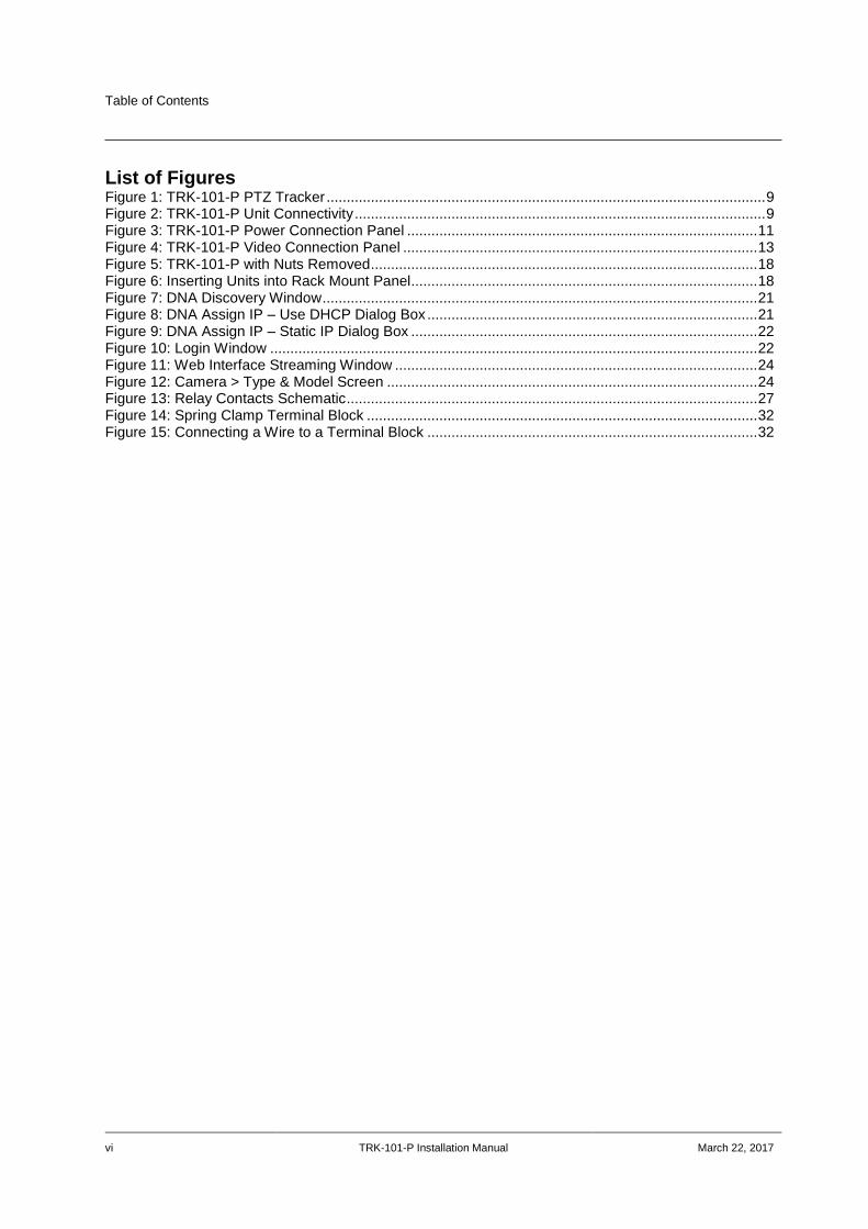
Table of Contents
vi TRK-101-P Installation Manual March 22, 2017
List of Figures
Figure 1: TRK-101-P PTZ Tracker ............................................................................................................. 9 Figure 2: TRK-101-P Unit Connectivity ...................................................................................................... 9 Figure 3: TRK-101-P Power Connection Panel ....................................................................................... 11 Figure 4: TRK-101-P Video Connection Panel ........................................................................................ 13 Figure 5: TRK-101-P with Nuts Removed ................................................................................................ 18 Figure 6: Inserting Units into Rack Mount Panel...................................................................................... 18 Figure 7: DNA Discovery Window ............................................................................................................ 21 Figure 8: DNA Assign IP – Use DHCP Dialog Box .................................................................................. 21 Figure 9: DNA Assign IP – Static IP Dialog Box ...................................................................................... 22 Figure 10: Login Window ......................................................................................................................... 22 Figure 11: Web Interface Streaming Window .......................................................................................... 24 Figure 12: Camera > Type & Model Screen ............................................................................................ 24 Figure 13: Relay Contacts Schematic ...................................................................................................... 27 Figure 14: Spring Clamp Terminal Block ................................................................................................. 32 Figure 15: Connecting a Wire to a Terminal Block .................................................................................. 32
Document Scope and Purpose
March 22, 2017 TRK-101-P Installation Manual 1
Document Scope and Purpose The purpose of this document is to provide instructions and installation procedures for physically connecting the TRK-101-P unit. After completing the physical installation, additional setup and configurations are required before video analysis and detection can commence. For information on the unit setup and configuration, refer to the HTML Edition Units User’s Guide.
Note:
This document is intended for use by technical users who have a basic understanding of CCTV
camera/video equipment and LAN/WAN network connections.
Remarque:
Ce document est destiné aux utilisateurs techniciens qui possèdent des connaissances de base des
équipements vidéo/caméras de télésurveillance et des connexions aux réseaux LAN/WAN.
Warning:
Installation must follow safety, standards, and electrical codes as well as the laws that apply where the
units are being installed.
Avertissement:
L'installation doit respecter les consignes de sécurité, les normes et les codes électriques, ainsi que la
législation en vigueur sur le lieu d'implantation des unités.
Disclaimer
Users of FLIR products accept full responsibility for ensuring the suitability and considering the role of the product detection capabilities and their limitation as they apply to their unique site requirements.
FLIR Systems, Inc. and its agents make no guarantees or warranties to the suitability for the users’ intended use. FLIR Systems, Inc. accepts no responsibility for improper use or incomplete security and safety measures.
Failure in part or in whole of the installer, owner, or user in any way to follow the prescribed procedures or to heed WARNINGS and CAUTIONS shall absolve FLIR and its agents from any resulting liability.
Specifications and information in this guide are subject to change without notice.
Avis de non-responsabilité
Il incombe aux utilisateurs des produits FLIR de vérifier que ces produits sont adaptés et d'étudier le rôle des capacités et limites de détection du produit appliqués aux exigences uniques de leur site.
FLIR Systems, Inc. et ses agents ne garantissent d'aucune façon que les produits sont adaptés à l'usage auquel l'utilisateur les destine. FLIR Systems, Inc. ne pourra être tenu pour responsable en cas de mauvaise utilisation ou de mise en place de mesures de sécurité insuffisantes.
Le non respect de tout ou partie des procédures recommandées ou des messages d'AVERTISSEMENT ou d'ATTENTION de la part de l'installateur, du propriétaire ou de l'utilisateur dégagera FLIR Systems, Inc. et ses agents de toute responsabilité en résultant.
Les spécifications et informations contenues dans ce guide sont sujettes à modification sans préavis.
Document Scope and Purpose
2 TRK-101-P Installation Manual March 22, 2017
A Warning is a precautionary message that indicates a procedure or condition where there are
potential hazards of personal injury or death.
Avertissement est un message préventif indiquant qu'une procédure ou condition présente un risque
potentiel de blessure ou de mort.
A Caution is a precautionary message that indicates a procedure or condition where there are
potential hazards of permanent damage to the equipment and or loss of data.
Attention est un message préventif indiquant qu'une procédure ou condition présente un risque
potentiel de dommages permanents pour l'équipement et/ou de perte de données.
A Note is useful information to prevent problems, help with successful installation, or to provide
additional understanding of the products and installation.
Une Remarque est une information utile permettant d'éviter certains problèmes, d'effectuer une
installation correcte ou de mieux comprendre les produits et l'installation.
A Tip is information and best practices that are useful or provide some benefit for installation and use
of FLIR products.
Un Conseil correspond à une information et aux bonnes pratiques utiles ou apportant un avantage
supplémentaire pour l'installation et l'utilisation des produits FLIR.
Document Scope and Purpose
March 22, 2017 TRK-101-P Installation Manual 3
General Cautions and Warnings
This section contains information that indicates a procedure or condition where there are potential hazards.
SAVE ALL SAFETY AND OPERATING INSTRUCTIONS FOR FUTURE USE.
Although the unit is designed and manufactured in compliance with all applicable safety standards, certain hazards are present during the installation of this equipment.
To help ensure safety and to help reduce risk of injury or damage, observe the following:
Précautions et avertissements d'ordre général
Cette section contient des informations indiquant qu'une procédure ou condition présente des risques potentiels.
CONSERVEZ TOUTES LES INSTRUCTIONS DE SÉCURITÉ ET D'UTILISATION POUR POUVOIR VOUS Y RÉFÉRER ULTÉRIEUREMENT.
Bien que l'unité soit conçue et fabriquée conformément à toutes les normes de sécurité en vigueur, l'installation de cet équipement présente certains risques.
Afin de garantir la sécurité et de réduire les risques de blessure ou de dommages, veuillez respecter les consignes suivantes:
Warning:
The unit’s cover is an essential part of the product. Do not open or remove it.
Never operate the unit without the cover in place. Operating the unit without the cover poses a risk of fire and shock hazards.
Do not disassemble the unit or remove screws. There are no user serviceable parts inside the unit.
Only qualified trained personnel should service and repair this equipment.
Observe local codes and laws and ensure that installation and operation are in accordance with fire, security and safety standards.
Avertissement:
Le cache de l'unité est une partie essentielle du produit. Ne les ouvrez et ne les retirez pas.
N'utilisez jamais l'unité sans que le cache soit en place. L'utilisation de l'unité sans cache présente un risque d'incendie et de choc électrique.
Ne démontez pas l'unité et ne retirez pas ses vis. Aucune pièce se trouvant à l'intérieur de l'unité ne nécessite un entretien par l'utilisateur.
Seul un technicien formé et qualifié est autorisé à entretenir et à réparer cet équipement.
Respectez les codes et réglementations locaux, et assurez-vous que l'installation et l'utilisation sont conformes aux normes contre l'incendie et de sécurité.
Document Scope and Purpose
4 TRK-101-P Installation Manual March 22, 2017
Warning:
1. Read the installation instructions before you connect the unit to a power source.
2. Electrical safety should always be observed. All electrical connections must be performed by
a certified electrician. 3. Use the supplied power supply and protect against static electricity, ground faults and power
surges.
4. The unit uses a three-wire power cord to make sure that the product is properly grounded
when in use. This is a safety feature. If the intended power outlet does not support three
prongs, one of which is a ground, contact an electrician to install the appropriate outlet.
NEVER remove or otherwise attempt to bypass the ground pin of the power cord. Do not
operate the unit in the absence of a suitably installed ground conductor.
5. If you use an extension cord with this system, make sure that the total ampere rating on the
products plugged into the extension cord does not exceed the extension cord ampere rating.
6. To avoid possible shock hazards or damaging the unit, assure that the positive and negative
of the power leads are properly connected to the terminal block connector before plugging it
into the unit or turning on the power source.
7. In the following situations, the electric power should be turned off immediately and
appropriate repairs, replacements or remedies should be taken if:
The power line is damaged, frayed or shows heavy wear.
The unit has been physically crushed or deformed.
The unit has been exposed to water.
The unit has been exposed to, or shows signs of damage from, fire, intense heat, heavy smoke, fumes, or vapors.
Electrical connections of the unit become abnormally hot or generate smoke.
The unit has been dropped, damaged or shows signs of loose internal parts.
The unit does not operate properly.

Document Scope and Purpose
March 22, 2017 TRK-101-P Installation Manual 5
Avertissement:
1. Lisez les instructions d'installation avant de brancher l'unité à une source d'alimentation
électrique.
2. Les consignes de sécurité électrique doivent toujours être respectées. Toutes les
connexions électriques doivent être effectuées par un électricien qualifié.
3. Utilisez l'alimentation fournie, et protégez l'unité contre l'électricité statique, les défauts de mise à la terre et les surtensions.
4. Si l'unité utilise un cordon d'alimentation à trois fils, assurez-vous que le produit est
correctement mis à la terre du produit lors de son utilisation. Ne retirez JAMAIS, et ne tentez
pas de contourner la broche de mise à la terre du cordon d'alimentation. N'utilisez pas l'unité
en l'absence d'un conducteur de mise à la terre installé correctement.
5. Si vous utilisez une rallonge avec ce système, assurez-vous que l'ampérage total des
produits branchés sur la rallonge ne dépasse pas l'ampérage nominal de celle-ci.
6. Pour éviter tout risque de choc électrique ou d'endommager l'unité, assurez-vous que les
bornes plus et moins de l'alimentation sont correctement raccordées au connecteur du bloc
de jonction avant de le brancher sur l'unité ou d'activer la source d'alimentation.
7. Dans les situations suivantes, l'alimentation électrique doit être coupée immédiatement, et
les réparations, remplacements ou solutions suivants doivent être effectués si :
Le cordon d'alimentation ou la prise (le cas échéant) est endommagé, effiloché ou très usé.
L'unité a subi un choc ou a été déformée.
L'unité a été exposée à de l'eau.
L'unité a été exposée à, ou montre des signes de dégâts par le feu, une chaleur intense, une fumée épaisse, des émanations ou des vapeurs.
Les connexions électriques chauffent de façon anormale ou produisent de la fumée.
L'unité est tombée, a été endommagée, ou certaines pièces internes semblent détachées.
L'unité ne fonctionne pas correctement.
Document Scope and Purpose
6 TRK-101-P Installation Manual March 22, 2017
Caution:
To avoid damage from overheating or unit failure, assure that there is sufficient temperature
regulation to support the unit’s requirements (cooling/heating). Operating temperature should be kept
in the range specified for the product (0° to 60°C/32° to 140°F), with no more than 95% non-
condensing humidity.
Attention:
Afin d'éviter tout dommage dû à une surchauffe ou toute panne de l'unité, assurez-vous que la
régulation de température est suffisante pour répondre aux exigences de l'unité
(refroidissement/chauffage). La température de fonctionnement doit être maintenue dans la plage de
température spécifiée pour le produit (0° à 60°C/32° à 140°F), sans condensation d'humidité
supérieur à 95%.
Document Scope and Purpose
March 22, 2017 TRK-101-P Installation Manual 7
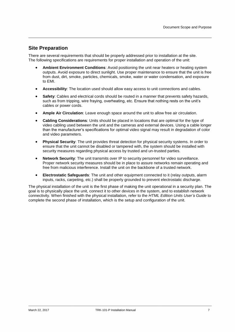
Site Preparation
There are several requirements that should be properly addressed prior to installation at the site. The following specifications are requirements for proper installation and operation of the unit:
Ambient Environment Conditions: Avoid positioning the unit near heaters or heating system outputs. Avoid exposure to direct sunlight. Use proper maintenance to ensure that the unit is free from dust, dirt, smoke, particles, chemicals, smoke, water or water condensation, and exposure to EMI.
Accessibility: The location used should allow easy access to unit connections and cables.
Safety: Cables and electrical cords should be routed in a manner that prevents safety hazards, such as from tripping, wire fraying, overheating, etc. Ensure that nothing rests on the unit’s cables or power cords.
Ample Air Circulation: Leave enough space around the unit to allow free air circulation.
Cabling Considerations: Units should be placed in locations that are optimal for the type of video cabling used between the unit and the cameras and external devices. Using a cable longer than the manufacturer’s specifications for optimal video signal may result in degradation of color and video parameters.
Physical Security: The unit provides threat detection for physical security systems. In order to ensure that the unit cannot be disabled or tampered with, the system should be installed with security measures regarding physical access by trusted and un-trusted parties.
Network Security: The unit transmits over IP to security personnel for video surveillance. Proper network security measures should be in place to assure networks remain operating and free from malicious interference. Install the unit on the backbone of a trusted network.
Electrostatic Safeguards: The unit and other equipment connected to it (relay outputs, alarm inputs, racks, carpeting, etc.) shall be properly grounded to prevent electrostatic discharge.
The physical installation of the unit is the first phase of making the unit operational in a security plan. The goal is to physically place the unit, connect it to other devices in the system, and to establish network connectivity. When finished with the physical installation, refer to the HTML Edition Units User’s Guide to complete the second phase of installation, which is the setup and configuration of the unit.

8 TRK-101-P Installation Manual March 22, 2017
Introduction
March 22, 2017 TRK-101-P Installation Manual 9
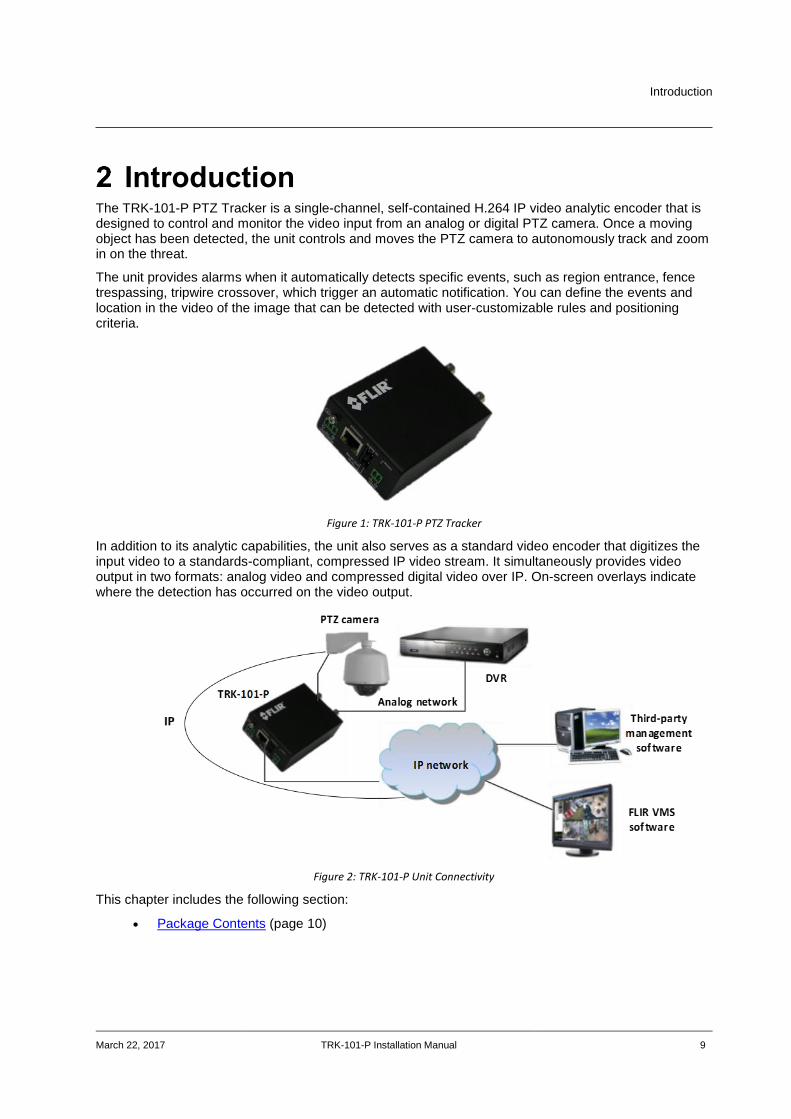
Introduction The TRK-101-P PTZ Tracker is a single-channel, self-contained H.264 IP video analytic encoder that is designed to control and monitor the video input from an analog or digital PTZ camera. Once a moving object has been detected, the unit controls and moves the PTZ camera to autonomously track and zoom in on the threat.
The unit provides alarms when it automatically detects specific events, such as region entrance, fence trespassing, tripwire crossover, which trigger an automatic notification. You can define the events and location in the video of the image that can be detected with user-customizable rules and positioning criteria.
Figure 1: TRK-101-P PTZ Tracker
In addition to its analytic capabilities, the unit also serves as a standard video encoder that digitizes the input video to a standards-compliant, compressed IP video stream. It simultaneously provides video output in two formats: analog video and compressed digital video over IP. On-screen overlays indicate where the detection has occurred on the video output.
Figure 2: TRK-101-P Unit Connectivity
This chapter includes the following section:
Package Contents (page 10)
Introduction
10 TRK-101-P Installation Manual March 22, 2017
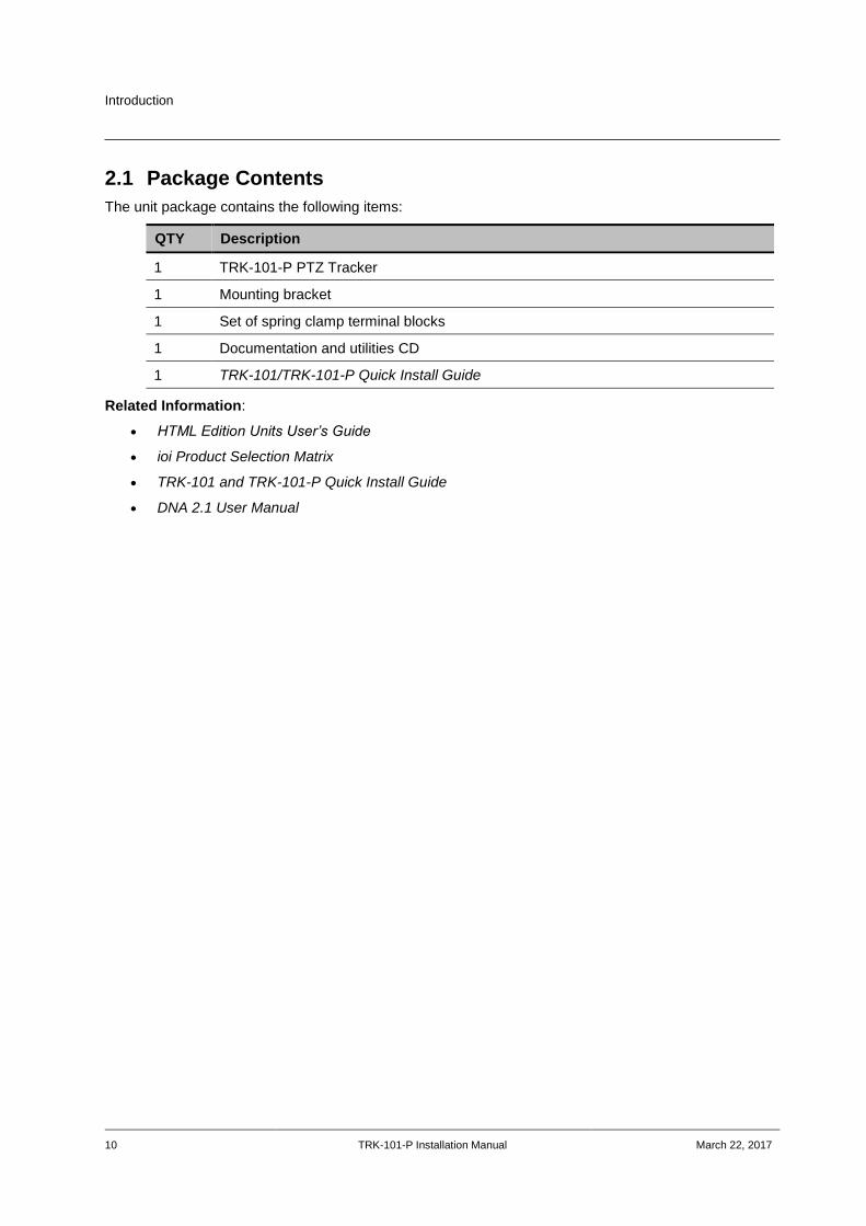
2.1 Package Contents
The unit package contains the following items:
QTY Description
1 TRK-101-P PTZ Tracker
1 Mounting bracket
1 Set of spring clamp terminal blocks
1 Documentation and utilities CD
1 TRK-101/TRK-101-P Quick Install Guide
Related Information:
HTML Edition Units User’s Guide
ioi Product Selection Matrix
TRK-101 and TRK-101-P Quick Install Guide
DNA 2.1 User Manual
Hardware Description
March 22, 2017 TRK-101-P Installation Manual 11
Hardware Description
3.1 Power Connection Panel
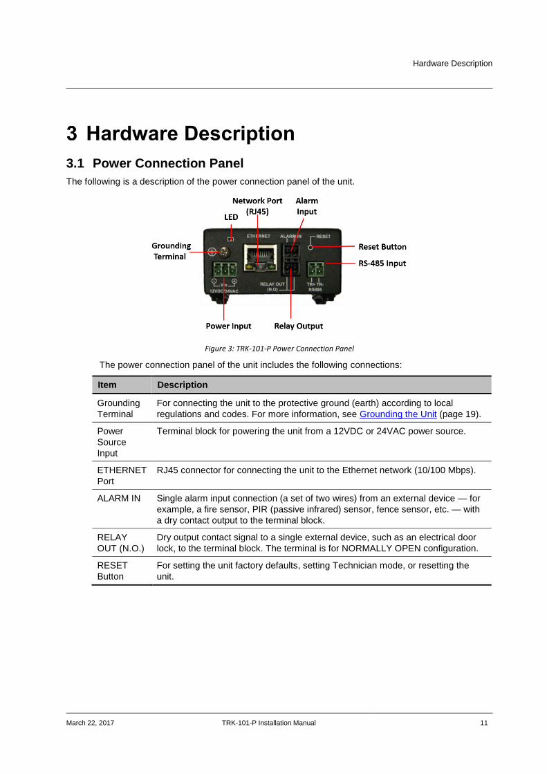
The following is a description of the power connection panel of the unit.
Figure 3: TRK-101-P Power Connection Panel
The power connection panel of the unit includes the following connections:
Item Description
Grounding
Terminal
For connecting the unit to the protective ground (earth) according to local
regulations and codes. For more information, see Grounding the Unit (page 19).
Power
Source
Input
Terminal block for powering the unit from a 12VDC or 24VAC power source.
ETHERNET
Port
RJ45 connector for connecting the unit to the Ethernet network (10/100 Mbps).
ALARM IN Single alarm input connection (a set of two wires) from an external device — for
example, a fire sensor, PIR (passive infrared) sensor, fence sensor, etc. — with
a dry contact output to the terminal block.
RELAY
OUT (N.O.)
Dry output contact signal to a single external device, such as an electrical door
lock, to the terminal block. The terminal is for NORMALLY OPEN configuration.
RESET
Button
For setting the unit factory defaults, setting Technician mode, or resetting the
unit.
Hardware Description
12 TRK-101-P Installation Manual March 22, 2017
Item Description
LEDs The LEDs indicates several status conditions:
Off: The unit is resetting.
Flashing green (300ms intervals): The firmware is booting.
Flashing green (one second intervals): The firmware has booted
successfully, the encoder is connected to the network, and unit is
operating normally.
Steady red: Failure in the first phase of the boot. Requires resetting the
unit.
Flashing red: Failure in the second phase of the boot. Requires resetting
the unit.
Steady yellow: Reset button was pressed for 5-15 seconds and entered
Technician mode. Requires resetting the unit.
Flashing yellow (500ms intervals): The unit is in Factory Default mode.
To enter this mode, press the Reset button for 15-30 seconds. The LED
changes from steady state to flashing after five seconds. The unit’s
firmware returns to the factory defaults. When finished, the LED displays
flashing green.
Note:
If the LED is pressed for more than 30 seconds, it will flash red,
indicating an error. In this case, disconnect the unit and reboot.
TR+/TR-
RS485
Two-pin terminal block connector to connect an RS-485 cable from and control a
PTZ camera.
Hardware Description
March 22, 2017 TRK-101-P Installation Manual 13
3.1.1 Video Connection Panel
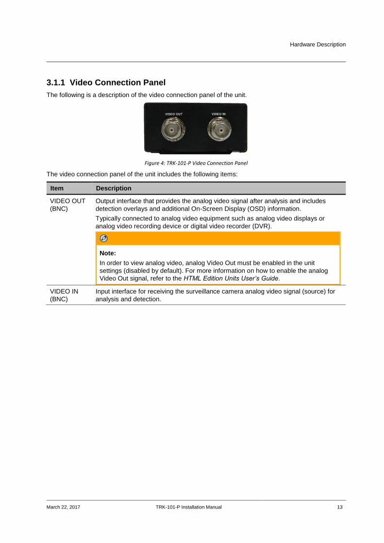
The following is a description of the video connection panel of the unit.
Figure 4: TRK-101-P Video Connection Panel
The video connection panel of the unit includes the following items:
Item Description
VIDEO OUT
(BNC)
Output interface that provides the analog video signal after analysis and includes
detection overlays and additional On-Screen Display (OSD) information.
Typically connected to analog video equipment such as analog video displays or
analog video recording device or digital video recorder (DVR).
Note:
In order to view analog video, analog Video Out must be enabled in the unit
settings (disabled by default). For more information on how to enable the analog
Video Out signal, refer to the HTML Edition Units User’s Guide.
VIDEO IN
(BNC)
Input interface for receiving the surveillance camera analog video signal (source) for
analysis and detection.

14 TRK-101-P Installation Manual March 22, 2017

System Requirements
March 22, 2017 TRK-101-P Installation Manual 15
System Requirements Item Minimum System Requirement
Personal Computer Intel® Pentium® IV, 2.4GHz or higher with >1GB RAM
Monitor display with minimum 1024 x 768 resolution
(NVIDIA GeForce 6 Series or ATI Mobility Radeon 9500)
Operating System Microsoft Windows XP SP1 and above; Windows 7, 8, 8.1, and 10
Web Browser Internet Explorer 8, 9, 10, and 11
Network Card 10Base-T (10 Mbps) or 100Base-TX (100 Mbps) operation
Viewer ActiveX control plug-in for Microsoft Internet Explorer

16 TRK-101-P Installation Manual March 22, 2017
Installing and Connecting the Unit
March 22, 2017 TRK-101-P Installation Manual 17
Installing and Connecting the Unit This section describes how to install and connect the unit and includes the following sections:
Installing the Unit (page 17)
Connecting the Unit (page 19)
Resetting the Unit (page 28)
Note:
After connecting the unit, proceed to configure the unit as described in the HTML Edition
Units User’s Guide.
5.1 Installing the Unit
The unit can be installed and mounted next to the camera (inside the camera enclosure).
Alternatively, the unit can be installed inside an equipment room on a shelf or in a rack using the rack mount panel that is available as an optional accessory.
When installing the unit make sure that:
It is securely tied down and cannot be easily dislodged
Operating temperatures, at all times, are kept between the minimum/maximum allowed
Proper ventilation is provided so that the air is free to circulate around the unit The unit is protected from direct weather conditions (for example, sunlight, rain, dust, etc.)
Caution:
To avoid damage from overheating or unit failure, assure that there is sufficient temperature
regulation to support the unit’s requirements (cooling/heating). Operating temperature
should be kept in the range specified for the product (0° to 60°C/32° to 140°F), with no more
than 95% non-condensing humidity.
Attention:
Afin d'éviter tout dommage dû à une surchauffe ou toute panne de l'unité, assurez-vous que
la régulation de température est suffisante pour répondre aux exigences de l'unité
(refroidissement/chauffage). La température de fonctionnement doit être maintenue dans la
plage de température spécifiée pour le produit (0° à 60°C/32° à 140°F), sans condensation
d'humidité supérieur à 95%.

Installing and Connecting the Unit
18 TRK-101-P Installation Manual March 22, 2017
5.1.1 Assembling the Unit in a Rack Mount Panel (Optional Accessory)
Up to 10 units can be mounted on a single rack mount panel. After the units have been assembled in the rack mount panel, the panel can be installed in a standard 19-inch rack.
To assemble units in a rack mount panel:
1. Remove the nut and washer from each of the two video connectors on the video connection panel of the unit.
Figure 5: TRK-101-P with Nuts Removed
2. Attach each unit to the rear side of the rack mount panel by inserting it through the holes as
shown below.
Figure 6: Inserting Units into Rack Mount Panel
3. Fasten each unit using the nuts and washers removed in step 1, making sure to first place
the washer on each video connector before tightening the nut on the video connector.
4. Repeat steps 1 through 3 for each of the units you want to assemble on the rack mount
panel (up to 10 units can be assembled per panel).
5. Attach the rack mount panel to a 19" rack.

Installing and Connecting the Unit
March 22, 2017 TRK-101-P Installation Manual 19
5.2 Connecting the Unit
This section describes the procedures for connecting the unit and includes the following sub-sections:
Grounding the Unit (page 19)
Connecting the Unit to the Power Supply (page 19)
Using the DNA Utility to Connect the Unit to the Network (page 20)
Connecting the Video Source (Camera) to the Unit (page 23)
Configuring PTZ Camera Settings on the Encoder (page 24)
Connecting the Analog Video Output to an Analog Device (page 24)
Connecting the Unit to Receive Alarms from External Devices (Alarm Inputs) (page 26)
Connecting the Unit to Control an External Device (Using Relay Outputs) (page 27)
5.2.1 Grounding the Unit
The unit must be grounded according to local regulations and codes.
To ground the unit
1. Loosen the screw of the grounding terminal located on the power connection panel of the
unit. See Figure 4: TRK-101-P Video Connection Panel (page 18).
2. Attach a properly rated ground cable. Make sure the ring/spade terminal of the grounding
cable is between the toothed washers. Tighten the screw.
3. Ensure that the other end of the ground cable is connected to protective earth according to
local regulations and codes.
5.2.2 Connecting the Unit to the Power Supply
Before connecting to the power, review the warnings in the Document Scope and Purpose (page 1).
Use a 12VDC/24VAC external power supply with suitable over current protection. Connect the power supply wires to the positive and negative inputs on the terminal block connector labeled 12VDC/24VAC. See Power Connection Panel (page 11).
Warning:
1. To prevent bodily injury or damage to the unit, use only properly rated and approved power
supplies and/or AC adaptors.
2. Make sure that the power supply matches the required specifications. Electrical safety should
always be observed.
Avertissement:
1. Pour prévenir toute blessure corporelle ou tout endommagement de l'unité, n'utilisez que des
alimentations et/ou des adaptateurs secteur correctement classifiés et approuvés.
2. Assurez-vous que l'alimentation corresponde aux spécifications requises. Les consignes de
sécurité électrique doivent toujours être respectées.
Following are the recommended AC adaptor specifications:
Power Adaptor Output: 12VDC, 1A, 12W
To power to the unit using a power outlet
1. Connect the AC adaptor output to the terminal block on the unit’s power connection panel. 2. Connect the AC adaptor to the power outlet.
Installing and Connecting the Unit
20 TRK-101-P Installation Manual March 22, 2017
5.2.3 Using the DNA Utility to Connect the Unit to the Network
By default, the unit is shipped with the factory default IP address 192.168.123.10.
The Discovery Network Assistant (DNA) is a user-friendly utility that is designed to easily discover and configure FLIR Professional Security edge devices on a network. The DNA tool has a simple user interface and does not require any installation. The software is provided as a single, standalone executable that runs on any PC.
Note:
Before connecting the unit to the network, set the unit IP address according to your specific network
requirements to avoid address conflicts. Refer to the instructions in this section on how to change the
unit’s IP addresses.
DNA provides a central location for listing all the supported FLIR Professional Security camera models accessible over the network. Once listed, each camera can be right-clicked to access and change the network settings. If the network settings are changed for some reason, a new search will relist the units. The units may then be configured via the web interface.
If FLIR’s Latitude VMS is being used, configure the unit with a static IP address rather than with DHCP. This ensures that the IP address will not automatically change in the future and interfere with configurations and communication.
The camera must be made accessible for setting network addresses.
Note:
For detailed guidelines about DNA and its usage, refer to the DNA 2.1 User Manual, which is included
in the CD provided with the camera.
If your network uses firewalls, you must configure them to support communication among the units and computers running the Internet browser used to connect to the TRK-101-P web interface. After connecting the unit to the network, check that the unit can be found on the network as is described below.
To connect a unit to the network
Connect a PC/laptop directly to the unit using a network cable connected to the Ethernet
port located on the front panel of the unit. See Figure 3: TRK-101-P Power Connection
Panel (page 9).
Change the IP address according to your specific requirements. See the following section.
Disconnect the unit from your PC/laptop.
Connect the unit to the system network as follows:
Connect the network cable to the Ethernet port located on the front panel of the unit.
See Figure 3: TRK-101-P Power Connection Panel (page 11).
Connect the other network cable end to the network switch/hub.
Installing and Connecting the Unit
March 22, 2017 TRK-101-P Installation Manual 21
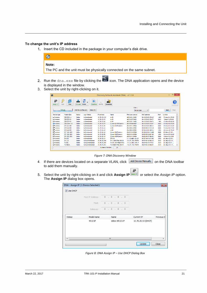
To change the unit’s IP address
Insert the CD included in the package in your computer’s disk drive.
Note:
The PC and the unit must be physically connected on the same subnet.
Run the dna.exe file by clicking the icon. The DNA application opens and the device
is displayed in the window. Select the unit by right-clicking on it.
Figure 7: DNA Discovery Window
If there are devices located on a separate VLAN, click on the DNA toolbar
to add them manually.
Select the unit by right-clicking on it and click Assign IP or select the Assign IP option. The Assign IP dialog box opens.
Figure 8: DNA Assign IP – Use DHCP Dialog Box
Installing and Connecting the Unit
22 TRK-101-P Installation Manual March 22, 2017
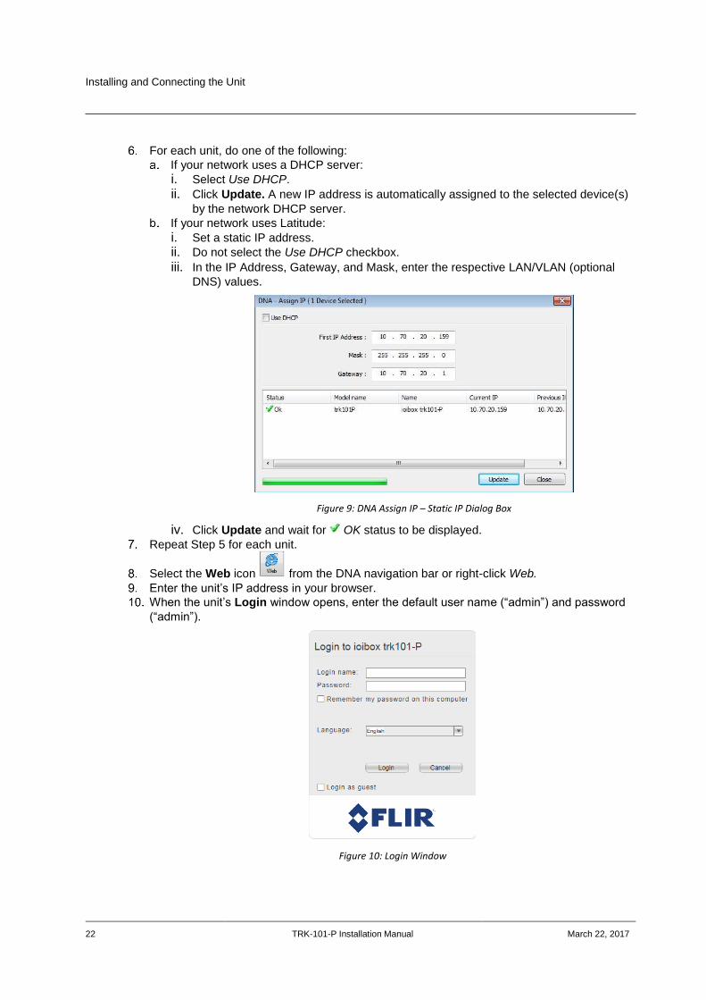
For each unit, do one of the following:
If your network uses a DHCP server:
i. Select Use DHCP.
ii. Click Update. A new IP address is automatically assigned to the selected device(s)
by the network DHCP server.
If your network uses Latitude:
i. Set a static IP address.
ii. Do not select the Use DHCP checkbox.
iii. In the IP Address, Gateway, and Mask, enter the respective LAN/VLAN (optional
DNS) values.
Figure 9: DNA Assign IP – Static IP Dialog Box
iv. Click Update and wait for OK status to be displayed.
Repeat Step 5 for each unit.
Select the Web icon from the DNA navigation bar or right-click Web.
Enter the unit’s IP address in your browser.
When the unit’s Login window opens, enter the default user name (“admin”) and password
(“admin”).
Figure 10: Login Window

Installing and Connecting the Unit
March 22, 2017 TRK-101-P Installation Manual 23
Note:
User name and password are case-sensitive.
The unit’s user interface opens.
Figure 11: TRK-101-P Live Screen
5.2.4 Connecting the Video Source (Camera) to the Unit
The unit is designed to accept a composite video signal (1Vp-p) from an analog PTZ camera. Video connections should use a 75Ω cable and should not be longer than 30 meters (98 feet).
To connect the video source to the unit
1. Securely connect the video cable BNC connector to the analog video output of the camera
or video source.
2. Connect the other cable end to the VIDEO IN connection on the video connection panel of
the unit. See Figure 4: TRK-101-P Video Connection Panel (page 13).
To set the unit’s video standard via its web interface
1. Enter the IP address of the unit in a browser. The unit’s Login window opens.
2. Login to the unit by entering your user name and password. The default user name and
password are both “admin”. The web interface opens.
3. If your computer requires ActiveX installation, install it now.

Installing and Connecting the Unit
24 TRK-101-P Installation Manual March 22, 2017
4. From the Live View window, access the Camera Setup by clicking Setup > Camera >
Streaming. The Streaming window opens.
Figure 12: Streaming Window
5. In the Video Standard field, select PAL or NTSC.
6. Click Apply to save the setting.
Note:
If the video standard is changed, all analytic settings will be deleted.
5.2.5 Configuring PTZ Camera Settings on the Encoder
PTZ camera settings are configured in the Setup > Camera > Type & Model screen in the web interface.
Figure 13: Camera > Type & Model Screen
Installing and Connecting the Unit
March 22, 2017 TRK-101-P Installation Manual 25
Note:
It is not necessary to perform the following procedure if you are configuring the PTZ camera from
Latitude instead of on the encoder.
To configure PTZ camera settings on the encoder
1. In the Camera Type area, select Pan/Tilt/Zoom (PTZ).
2. In the Camera Model section, from the drop-down lists, select the camera manufacturer,
model number, and maximum zoom.
3. In the Communication section, for all cameras except the FLIR 20X CP-4221-201 and FLIR
20X CP-4221-301 camera, from the drop-down lists, select the details for the following
settings:
Port
Protocol
Device ID
Baud rate
Parity
Start bits
Stop bits
Note:
If you select the FLIR 20X CP-4221-201 or FLIR 30X CP-4221-301 camera, the
above fields are disabled and the following fields are enabled: IP, Port, User, and
Password.
4. Click Start PTZ Setup to run the wizard to configure PTZ settings. For more information,
see section 5.3.1.2.1.1 in the HTML Edition Units User’s Guide.
5. When completed, click Apply to save settings.
Note:
1. When the PTZ functionality is enabled, the analog video output is disabled
automatically unless the unit is in DVR operating mode.
2. Any presets that were set previously will be discarded after clicking Apply.
Installing and Connecting the Unit
26 TRK-101-P Installation Manual March 22, 2017
5.2.6 Connecting the Analog Video Output to an Analog Device
Note:
The analog video output signal of the unit is disabled by default. Enable it if necessary using the unit’s
web interface.
The analog video output (composite video) contains the video from the camera combined with On-Screen Display (OSD) overlays such as detected objects, tracking boxes and trails, time stamp, alarm, camera status, and so on. These OSDs can be enabled and customized using the unit embedded HTML user interface.
The analog video output can be monitored using an analog monitor or recorded on a digital video recorder (DVR). For more information, refer to the HTML Edition Units User’s Guide.
To connect the unit analog video output to an analog device
Using video coax 75Ω cable with BNC connectors, connect the VIDEO OUT of the unit to the
analog device Video Input (for example, the VIDEO IN of a monitor or DVR).
Note:
Make sure the unit and the external analog equipment support the same video standard
(PAL/NTSC).
5.2.7 Connecting the Unit to Receive Alarms from External Devices (Alarm Inputs)
The unit supports receiving alarms from external devices such as sensors and doors, enabling it to trigger automatic responses on the unit. The unit supports a single alarm input from an external device. The alarm input includes two connecting terminals.
Warning:
1. Only dry contacts can be connected to the unit’s ALARM IN terminals. An external device
must fully close or fully open the circuit between the unit’s ALARM IN terminals.
2. Disconnect power from the unit before performing the procedure.
Avertissement:
1. Seuls des contacts secs peuvent être branchés aux terminaux ALARM IN de l'unité. Un
appareil externe doit complètement ouvrir ou complètement fermer le circuit entre les
terminaux ALARM IN de l'unité.
2. Débranchez l'alimentation de l'unité avant d'effectuer la procedure.
To connect an external alarm to the unit
1. Connect the leads from the external device dry contact output using the spring clamp
terminal block into the terminals marked ALARM IN (-) and (+). See Connecting Leads to a
Spring Clamp Terminal Block (page 32). The two terminals are located at the bottom of the
terminal block. See Figure 3: TRK-101-P Power Connection Panel (page 11).
2. Connect the terminal block to the external devices connector on the power connection panel
of the unit. See Figure 3: TRK-101-P Power Connection Panel (page 11).
3. Connect the other end of the cable to the alarm out (dry contact) of the alarm device/sensor.
Installing and Connecting the Unit
March 22, 2017 TRK-101-P Installation Manual 27
5.2.8 Connecting the Unit to Control an External Device (Using Relay Outputs)
You can use the relay output of the unit to provide an indication signal for controlling external devices, such as door locks, lights, etc. The relay output of the unit can be activated as a response to events and alerts. For more information on incident responses and relay outputs, refer to the HTML Edition Units User’s Guide.
Warning:
The signal from the relay output of the unit must be used as an indicator and not for direct control of a
device.
Avertissement:
Le signal provenant de la sortie relais de l'unité doit être utilisé comme indicateur et non pas pour
contrôler directement un appareil.
Caution:
To prevent damage to the unit, do not exceed the voltage and current ratings for the relay terminals.
Attention:
Pour prévenir tout endommagement de l'unité, ne dépassez pas les valeurs de courant et de tension
pour les terminaux relais.
Relay Output Specifications
Maximum current 1A @ 30VDC
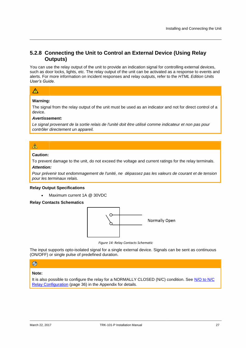
Relay Contacts Schematics
Figure 14: Relay Contacts Schematic
The input supports opto-isolated signal for a single external device. Signals can be sent as continuous (ON/OFF) or single pulse of predefined duration.
Note:
It is also possible to configure the relay for a NORMALLY CLOSED (N/C) condition. See N/O to N/C
Relay Configuration (page 36) in the Appendix for details.
Installing and Connecting the Unit
28 TRK-101-P Installation Manual March 22, 2017
To connect a device controller to a relay output of the unit
1. Connect the leads from the external device controller to the respective terminal points on the
spring clamp terminal block according to your requirements (NORMALLY OPEN or
NORMALLY CLOSED configuration). See Connecting Leads to a Spring Clamp Terminal
Block (page 32). The three terminal points for the relay output are located at the bottom left
of the terminal block. See Figure 3: TRK-101-P Power Connection Panel (page 11).
2. Connect the terminal block to the external devices connector on the power connection panel
of the unit. See Figure 3: TRK-101-P Power Connection Panel (page 11).
3. Connect the other end of the cable to the external controller, which receives the signal from
the unit and controls/powers the external device.
5.3 Resetting the Unit
The unit can be reset as follows:
Reset Using the RESET Button (page 28)
Reset by Removing the Power Supply (page 28)
5.3.1 Reset Using the RESET Button
The unit has a reset button located on the power connection panel of the unit. See Figure 3: TRK-101-P Power Connection Panel (page 11).
To reset a unit using the RESET button
1. Insert a small pointed object into the hole labeled RESET on the power connection panel of
the unit.
2. Press in and release the button within 5 seconds. The unit resets to its last settings and the
LED flashes green.
5.3.2 Reset by Removing the Power Supply
The unit can be reset by turning off the power and then turning it on again.
To reset a unit by removing the power supply
1. Turn off or disconnect the power to the unit.
2. Turn on or reconnect the power to the unit. The unit restarts with the last settings.
Appendices
March 22, 2017 TRK-101-P Installation Manual 29
Appendices The appendix contains the following sections:
Technical Specifications (page 30)
Connecting Leads to a Spring Clamp Terminal Block (page 32)
Troubleshooting (page 33)
NO to NC Relay Configuration (page 36)
Appendices
30 TRK-101-P Installation Manual March 22, 2017
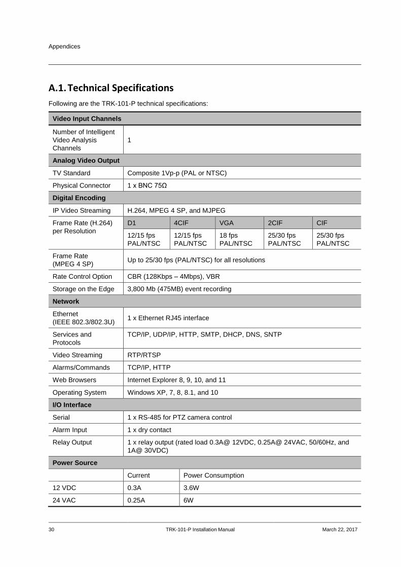
Technical Specifications
Following are the TRK-101-P technical specifications:
Video Input Channels
Number of Intelligent
Video Analysis
Channels
1
Analog Video Output
TV Standard Composite 1Vp-p (PAL or NTSC)
Physical Connector 1 x BNC 75Ω
Digital Encoding
IP Video Streaming H.264, MPEG 4 SP, and MJPEG
Frame Rate (H.264)
per Resolution
D1 4CIF VGA 2CIF CIF
12/15 fps
PAL/NTSC
12/15 fps
PAL/NTSC
18 fps
PAL/NTSC
25/30 fps
PAL/NTSC
25/30 fps
PAL/NTSC
Frame Rate
(MPEG 4 SP) Up to 25/30 fps (PAL/NTSC) for all resolutions
Rate Control Option CBR (128Kbps – 4Mbps), VBR
Storage on the Edge 3,800 Mb (475MB) event recording
Network
Ethernet
(IEEE 802.3/802.3U) 1 x Ethernet RJ45 interface
Services and
Protocols
TCP/IP, UDP/IP, HTTP, SMTP, DHCP, DNS, SNTP
Video Streaming RTP/RTSP
Alarms/Commands TCP/IP, HTTP
Web Browsers Internet Explorer 8, 9, 10, and 11
Operating System Windows XP, 7, 8, 8.1, and 10
I/O Interface
Serial 1 x RS-485 for PTZ camera control
Alarm Input 1 x dry contact
Relay Output 1 x relay output (rated load 0.3A@ 12VDC, 0.25A@ 24VAC, 50/60Hz, and
1A@ 30VDC)
Power Source
Current Power Consumption
12 VDC 0.3A 3.6W
24 VAC 0.25A 6W

Appendices
March 22, 2017 TRK-101-P Installation Manual 31
Physical Dimensions
Dimensions (mm) 68.5 x 36 x 118 mm (W x H x D)
Dimensions (in.) 2.7 x 1.42 x 4.62” (W x H x D)
Environmental Specifications
Operating
Temperature 0° to 60°C (32° to 140°F)
Operating Humidity 5% to 95% (non-condensing)
Certifications
Safety UL 60950-1:2007; IEC 60950-1:2005 (Ed. 2) + A1:2009 + A2:2013;
EN60950-1:2006 (Ed. 2) + A11:2009 + A1: 2010 + A12:2011 + A2:2013;
CAN/CSA-22.2 No. 60950-1-07 + A1:2011
Electromagnetic
Interference (EMC) FCC (47 CFR) Part 15 Subpart B, Class A; CE Class A; EN55032:2012; EN55024; CISPR 22: 2009 Class A; VCCI; RCM
Environmental RoHS, WEEE
Appendices
32 TRK-101-P Installation Manual March 22, 2017
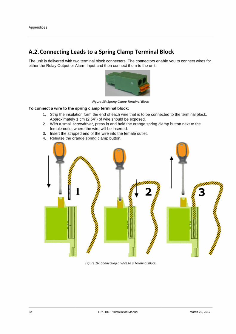
Connecting Leads to a Spring Clamp Terminal Block
The unit is delivered with two terminal block connectors. The connectors enable you to connect wires for either the Relay Output or Alarm Input and then connect them to the unit.
Figure 15: Spring Clamp Terminal Block
To connect a wire to the spring clamp terminal block:
1. Strip the insulation form the end of each wire that is to be connected to the terminal block.
Approximately 1 cm (2.54”) of wire should be exposed.
2. With a small screwdriver, press in and hold the orange spring clamp button next to the
female outlet where the wire will be inserted.
3. Insert the stripped end of the wire into the female outlet.
4. Release the orange spring clamp button.
Figure 16: Connecting a Wire to a Terminal Block
Appendices
March 22, 2017 TRK-101-P Installation Manual 33
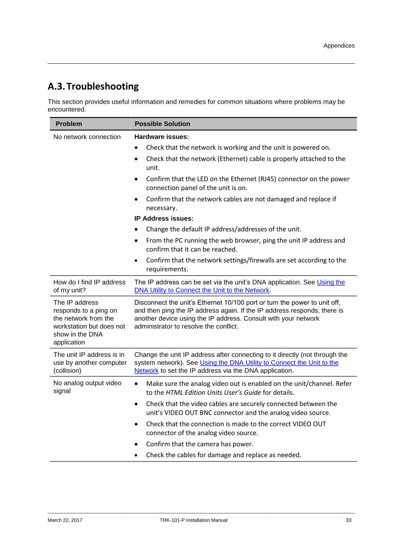
Troubleshooting
This section provides useful information and remedies for common situations where problems may be encountered.
Problem Possible Solution
No network connection Hardware issues:
Check that the network is working and the unit is powered on.
Check that the network (Ethernet) cable is properly attached to the unit.
Confirm that the LED on the Ethernet (RJ45) connector on the power connection panel of the unit is on.
Confirm that the network cables are not damaged and replace if necessary.
IP Address issues:
Change the default IP address/addresses of the unit.
From the PC running the web browser, ping the unit IP address and confirm that it can be reached.
Confirm that the network settings/firewalls are set according to the requirements.
How do I find IP address
of my unit?
The IP address can be set via the unit’s DNA application. See Using the
DNA Utility to Connect the Unit to the Network.
The IP address
responds to a ping on
the network from the
workstation but does not
show in the DNA
application
Disconnect the unit’s Ethernet 10/100 port or turn the power to unit off,
and then ping the IP address again. If the IP address responds, there is
another device using the IP address. Consult with your network
administrator to resolve the conflict.
The unit IP address is in
use by another computer
(collision)
Change the unit IP address after connecting to it directly (not through the
system network). See Using the DNA Utility to Connect the Unit to the
Network to set the IP address via the DNA application.
No analog output video
signal Make sure the analog video out is enabled on the unit/channel. Refer
to the HTML Edition Units User’s Guide for details.
Check that the video cables are securely connected between the unit’s VIDEO OUT BNC connector and the analog video source.
Check that the connection is made to the correct VIDEO OUT connector of the analog video source.
Confirm that the camera has power.
Check the cables for damage and replace as needed.

Appendices
34 TRK-101-P Installation Manual March 22, 2017
Problem Possible Solution
Bad output video quality Check the source video signal quality by connecting an analog monitor to the video source. If video quality is acceptable, connect the video source to the unit.
Check that the cables are connected securely. This includes junction boxes and amplifier that may be used.
Check that the camera settings are correct on the camera and in the unit. Refer to the HTML Edition Units User’s Guide for details.
Check that the camera lens is clean and unobstructed.
Check that the analog video signal is not being degraded due impedance caused by lengthy or worn cable, numerous connectors, ground loops interference, and so on.
Check that the cable length is within specification.
Streaming video image
is hanging (stopped) Confirm the unit’s video streaming settings. Refer to the HTML
Edition Units User’s Guide for details.
Refresh your browser screen (F5).
Check that the bandwidth and bit rate settings of the network are set properly.
Check that other processes and applications are not causing undue latency.
Check that the firewall analysis or blocking is not interfering with the video stream and supports the required ports and communication protocols.
Alarm inputs are not
working Check the unit settings to confirm that the alarm input is enabled.
Refer to the HTML Edition Units User’s Guide for details.
Check that a proper rule for an alarm input event has been defined in the unit. Refer to the HTML Edition Units User’s Guide for details.
Check that the alarm input (dry contact close/open) is being provided by the connected device.
Check that the unit is communicating through the network.
Check that the alarm input wires are connected securely.
Check that the alarm wires are paired in the terminal block in the right positions and according to requirements.
Appendices
March 22, 2017 TRK-101-P Installation Manual 35
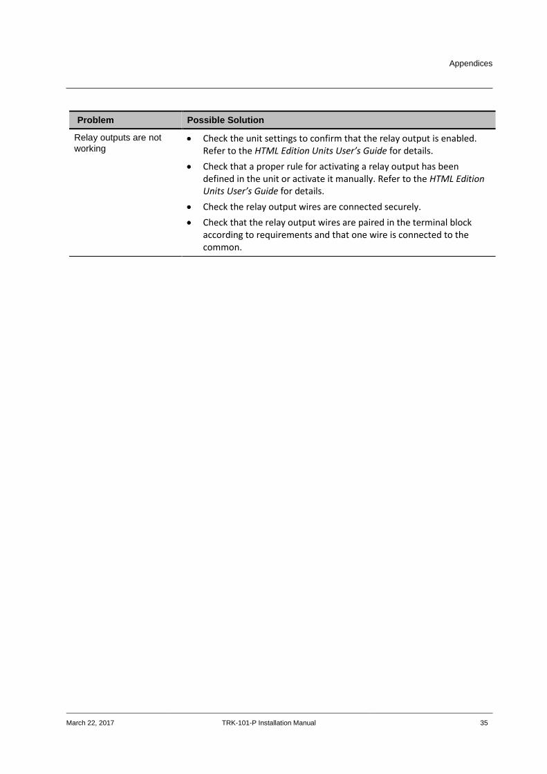
Problem Possible Solution
Relay outputs are not
working Check the unit settings to confirm that the relay output is enabled.
Refer to the HTML Edition Units User’s Guide for details.
Check that a proper rule for activating a relay output has been defined in the unit or activate it manually. Refer to the HTML Edition Units User’s Guide for details.
Check the relay output wires are connected securely.
Check that the relay output wires are paired in the terminal block according to requirements and that one wire is connected to the common.
Appendices
36 TRK-101-P Installation Manual March 22, 2017
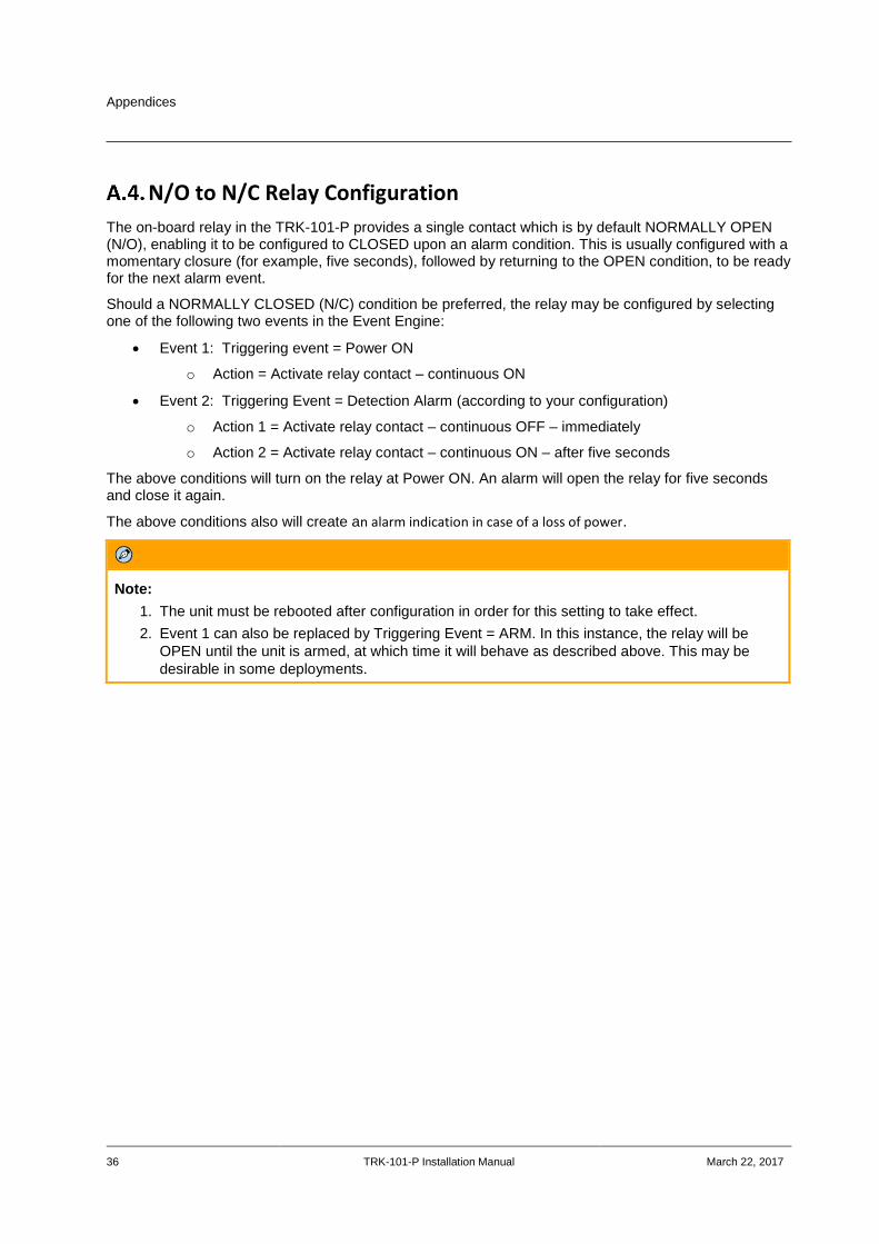
N/O to N/C Relay Configuration
The on-board relay in the TRK-101-P provides a single contact which is by default NORMALLY OPEN (N/O), enabling it to be configured to CLOSED upon an alarm condition. This is usually configured with a momentary closure (for example, five seconds), followed by returning to the OPEN condition, to be ready for the next alarm event.
Should a NORMALLY CLOSED (N/C) condition be preferred, the relay may be configured by selecting one of the following two events in the Event Engine:
Event 1: Triggering event = Power ON
o Action = Activate relay contact – continuous ON
Event 2: Triggering Event = Detection Alarm (according to your configuration)
o Action 1 = Activate relay contact – continuous OFF – immediately
o Action 2 = Activate relay contact – continuous ON – after five seconds
The above conditions will turn on the relay at Power ON. An alarm will open the relay for five seconds and close it again.
The above conditions also will create an alarm indication in case of a loss of power.
Note:
1. The unit must be rebooted after configuration in order for this setting to take effect.
2. Event 1 can also be replaced by Triggering Event = ARM. In this instance, the relay will be
OPEN until the unit is armed, at which time it will behave as described above. This may be
desirable in some deployments.
FLIR Systems, Inc. 6769 Hollister Ave. Goleta, CA 93117 USA PH: +1 805.964.9797 PH: +1 877.773.3547 (Sales) PH: +1 888.747.3547 (Support) FX: +1 805.685.2711 www.flir.com/security Corporate Headquarters FLIR Systems, Inc. 27700 SW Parkway Ave. Wilsonville, OR 97070 USA PH: +1 503.498.3547 FX: +1 503.498.3153
Document: TRK-101-P Installation Manual Version: 2 Date: March 22, 2017 Language: en-US