Tritium: Fleet-Wide Assessment Program Zigmund A. Karpa Director Environmental and Regulatory...
28
Tritium: Fleet-Wide Assessment Program Zigmund A. Karpa Director Environmental and Regulatory Affairs
-
Upload
julius-curtis-hodge -
Category
Documents
-
view
213 -
download
0
Transcript of Tritium: Fleet-Wide Assessment Program Zigmund A. Karpa Director Environmental and Regulatory...

Tritium: Fleet-Wide Assessment Program
Zigmund A. Karpa
Director Environmental and Regulatory Affairs

2
Assessment Project
Obtained Executive SponsorshipDeveloped Issue Statement Identified Goals and Objectives Established Project Team and Assigned
ResponsibilitiesDeveloped a Detailed Scope of Work

3
Primary Objectives of the Assessment
Identify and evaluate systems structures and components that contain or could potentially contain radioactively contaminated liquids;
Determine if the identified systems, structures and components have a potential pathway to the soils, groundwater or surface water;
Identify and evaluate the effectiveness of existing physical (i.e., secondary containment) and administrative controls (i.e. procedures) associated with each system, structure and component;
4
Objectives (continued)
Enhance our understanding of geologic and hydrogeologic characteristics; and
Ensure proficient communication of non-permitted radiological releases with the surrounding communities and other stakeholders.

5
Organization
Nuclear Executive Sponsor
Nuclear Corporate Project Team
• Chemistry
• Communications
• Engineering
• Environmental
• Licensing
• Project Management
• Public Affairs
• Radiation Protection
Stations Project Team
6
Project Management Responsibilities
Manager and track schedules; Lead periodic management status updates; Manage and coordinate all budget estimates and
projections; Assemble periodic management reports ; Develop flee-wide performance indicators and project
tracking mechanisms; Identify and track actions; Coordinate Quality Assurance/Quality Control; and Contract or provide oversight.

7
Environmental Affairs Responsibilities
Develop and Refine Templates;Manage base maps and final maps;Evaluate spills, accidental discharges and historic
releases;Document geologic and hydrogeologic conditions;Assess existing groundwater monitoring systems;Develop groundwater monitoring program; andAdminister environmental contracts.

8
Station Responsibilities
Designate point-of-contact and project team; Identify and map potential sources;Document material conditions;Document known and alleged spills, accidental
discharges and historical release;Assemble environmental data; Document results of evaluation process;

9
Station Responsibilities (continued)
Assist in risk evaluation process;Develop and implement corrective actions;Revise procedures to include management
program and system improvements; andMaintain files demonstrating the quality of the
evaluation process.

10
Scope of Work
Phase I Project PlanningPhase II Data GatheringPhase III Work Plan DevelopmentPhase IV Risk EvaluationPhase V Implementation of Risk
Reduction
Strategies

11
Phase I Project Planning
Develop detailed scheduleAssign project teams at corporate and each
stationCommunicate technical expectations and
deliverables to the stationsDevelop templates and technical data
management tools and protocolsDevelop project records retention programSchedule and conduct kick-off meetings
12
Phase II – Data Gathering
Identify and map potential sources Document material condition Document and map historical releases, spills and
accidental discharges; and Develop environmental baseline.

13
Primary Objectives of Data Gathering
To identify and map any system, structure or component that contained or potentially could contain radiological liquids and that had a viable pathway for a release to enter the environment;
To identify material condition of those systems, structures and components identified above;
To identify and map any historical release, spill or accidental discharge that had the potential to enter the environment; and
To document available regional and site specific geologic and hydrogeologic information.

14
Potential Sources Identified
Aboveground storage tanks
Containers Discharge canals Discharge lines Fuel pools Other vessels Plant penetrations Pumps Relief valves
Sumps Supply lines Surface impoundments
(Pits, ponds, lagoons and lakes)
Trenches Underground storage
tanks Vacuum breakers Valves and valve pits

15
Example: Logic Tree
Does the sump, drywellor trench contain or have the
potential to contain radioactivelycontaminated liquids?
Yes
No additionalevaluationrequired
Complete Sump,Drywell and Trench
Source IdentificationWorksheet
No
Is the sump, drywell ortrench against a wall or
on a slab that is in contactwith the soil or gravel?
Yes
NO
No
Is the sump, drywell ortrench locatedin a building?
Yes
16
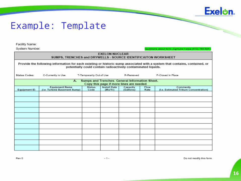
Example: Template
17
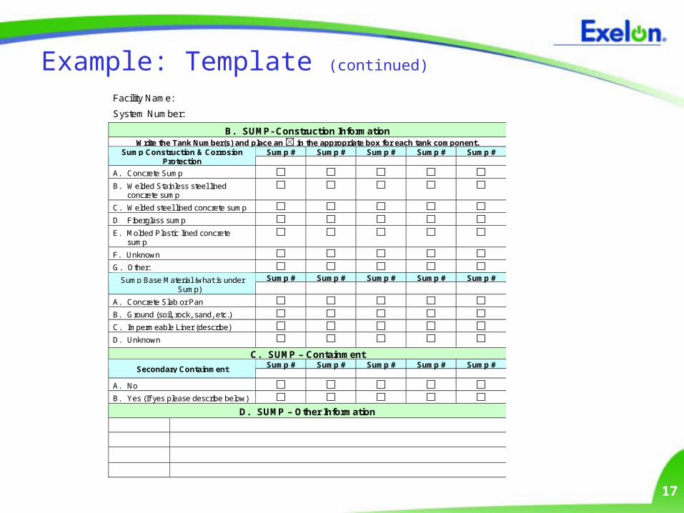
Example: Template (continued)
Facility Name:
System Number:
B. SUMP- Construction Information Write the Tank Number(s) and place an in the appropriate box for each tank component.
Sump # Sump # Sump # Sump # Sump # Sump Construction & Corrosion Protection
A. Concrete Sump
B. Welded Stainless steel lined concrete sump
C. Welded steel lined concrete sump
D Fiberglass sump
E. Molded Plastic lined concrete sump
F. Unknown
G. Other: Sump # Sump # Sump # Sump # Sump # Sump Base Material (what is under
Sump)
A. Concrete Slab or Pan
B. Ground (soil, rock, sand, etc.)
C. Impermeable Liner (describe)
D. Unknown
C. SUMP – Containment Sump # Sump # Sump # Sump # Sump #
Secondary Containment
A. No
B. Yes (If yes please describe below)
D. SUMP – Other Information

18
Example: Template (continued)
Facility Name:
System Number:
E. TRENCH - Construction Information Trench # Trench # Trench # Trench # Trench # Trench Construction & Corrosion Protection
A. Concrete
B. Lined Concrete
C. Other:
Trench # Trench # Trench # Trench # Trench # Trench Base Material (what is under Trench)
A. Concrete Slab or Pan
B. Ground (soil, rock, sand, etc.)
C. Impermeable Liner (describe)
D. Unknown
F. TRENCH – Other Information
Name of the Individual Completing Form:
Telephone Number:
Date Completed:
Note: The location of each sump, drywell and trench must be depicted on a map.

19
Document Material Condition
Description – Age, dimensions, location, design capacity, etc.
Fluid concentrations – Estimate of the maximum concentrations of radioactive material in each system or component (i.e. historic or existing);
Controls and Inspections – Equipment and system components inspection frequencies and types etc.
Maintenance Records – Records of any repairs or replacements related to equipment that is known or suspected of having leaked radioactively contaminated water.

20
Quality Control
A cross functional team with representatives from Chemistry, Engineering, and Radiation Protection was assembled.
The team was responsible for:• Comparing templates from the stations to identify
potential gaps;• Holding meetings with the stations to challenge the
data included in each source identification worksheet• Documenting the rational for including or removing
systems, structures or components form the source identification worksheets

21
Document Historical Releases, Spills and Accidental Discharges
Identify and list historical releases as recorded in accordance with 10 CFR 50.75.g.
Review available records and interview knowledgeable personnel to identify accidental discharges, spill areas, and disposal areas.
Document all alleged events and disposal areas that have potentially impacted the environment and record the information in a corporate-supplied template.
Map all identified historical releases, spills and accidental discharges
22
Release Data Collected
Date of event; Source of release; Location of release; Area Impacted; Media impacted (i.e., soil,
groundwater or surface water);
Material released including concentrations, if known;
Amount of material released;
Remediation efforts implemented; and
Post remediation analysis, if any.

23
Develop Environmental Baseline
Regional and site specific-geology;
Regional and site specific-hydrogeology;
On-site groundwater monitoring wells;
On-site groundwater dewatering systems and recovery wells;
Existing and historic monitoring programs;
Soil logs, locations and data;
Groundwater elevations, contour maps and analytical data;
Sediment sample locations and data; and
REMP and RETS data and reports.

24
Quality Control
A team of environmental professionals from Exelon, the Stations and a Consultant was assembled to evaluate the releases.
The team was responsible for:• Evaluating each release to determine if groundwater
was potentially impacted or could be impacted in the future;
• If a potential impact existed, identify the spill area was for further evaluation; and
• Documenting the rational for including or excluding the area for further evaluation.

25
Hydrogeologic Work Plans
Site Specific investigation work plans were developed to:
Characterize the hydrogeologic conditions at the property including subsurface soil types, the presence or absence of confining layers, and the direction and rate of groundwater flow;
Characterize the groundwater/surface water interaction at the Station, including a determination of the surface water flow regime;
Evaluate groundwater quality at the Station including the vertical and horizontal extent of any tritium in the groundwater;

26
Hydrogeologic Work Plans (continued)
Define the probable sources and estimate quantity of any tritium released at the station;
Evaluate potential human, ecological or environmental receptors of tritium released to groundwater, if any;
Evaluate whether interim response activities were warranted to address the groundwater; and
Provide a technical basis to evaluate possible remedial alternatives for tritium impacts identified at the station.

27
Hydrogeologic Reports
Hydrogeologic Work Plans were implemented; Hydrogeologic Reports were generated and provided to
the NRC and State agencies as appropriate; Meetings were held with the NRC and various state
agencies to review the results of the Reports; The Reports were posted on Exelon’s external web page; A long term monitoring program was developed and
institutionalized through procedures; and The results of subsequent sampling episodes are included
as part of each Station’s REMP.

28
QUESTIONS?