TRIPLE Thermo US06 - Hudson Reed Canadacanada.hudsonreed.com/media/pdf_files/us_TRIPLE1.pdfTRIPLE...
12
TRIPLE CONTROL THERMOSTATIC SHOWER VALVE OWNER’S GUIDE These instructions cover all Triple Control Thermostatic Shower Valve Models Shower control handles and concealing plate may differ depending on Model Issue two
Transcript of TRIPLE Thermo US06 - Hudson Reed Canadacanada.hudsonreed.com/media/pdf_files/us_TRIPLE1.pdfTRIPLE...

TRIPLE CONTROLTHERMOSTATIC SHOWER VALVE
OWNER’S GUIDEThese instructions cover all Triple Control Thermostatic Shower Valve Models
Show
er
cont
rol h
andl
es
and
conc
ealin
g pla
te
may
diff
er d
epen
ding
on M
odel
I s s u e t w o
TRIPLE Thermo US06 5/9/06 9:58 am Page 2
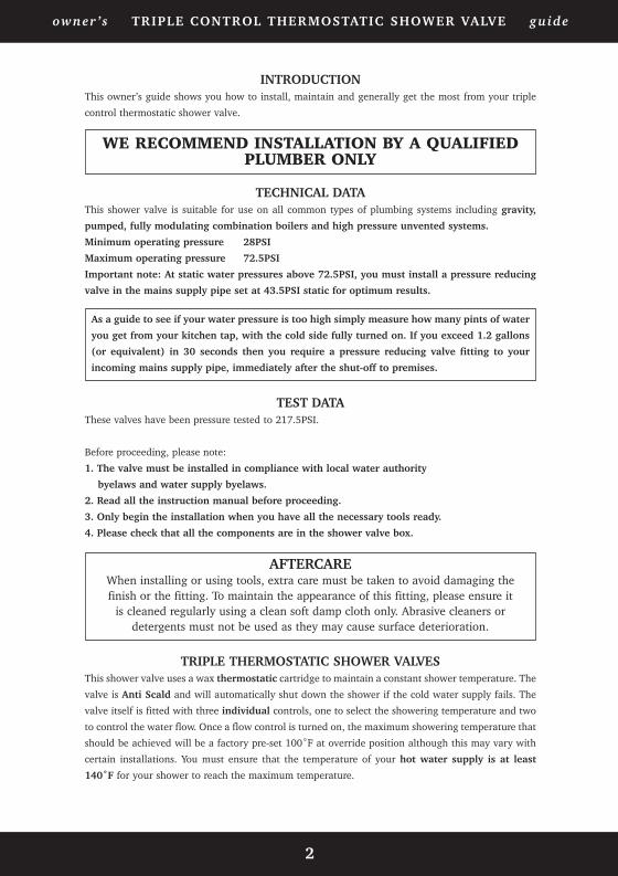
INTRODUCTIONThis owner’s guide shows you how to install, maintain and generally get the most from your triple
control thermostatic shower valve.
WE RECOMMEND INSTALLATION BY A QUALIFIEDPLUMBER ONLY
TECHNICAL DATAThis shower valve is suitable for use on all common types of plumbing systems including gravity,
pumped, fully modulating combination boilers and high pressure unvented systems.
Minimum operating pressure 28PSI
Maximum operating pressure 72.5PSI
Important note: At static water pressures above 72.5PSI, you must install a pressure reducing
valve in the mains supply pipe set at 43.5PSI static for optimum results.
TEST DATAThese valves have been pressure tested to 217.5PSI.
Before proceeding, please note:
1. The valve must be installed in compliance with local water authority
byelaws and water supply byelaws.
2. Read all the instruction manual before proceeding.
3. Only begin the installation when you have all the necessary tools ready.
4. Please check that all the components are in the shower valve box.
TRIPLE THERMOSTATIC SHOWER VALVESThis shower valve uses a wax thermostatic cartridge to maintain a constant shower temperature. The
valve is Anti Scald and will automatically shut down the shower if the cold water supply fails. The
valve itself is fitted with three individual controls, one to select the showering temperature and two
to control the water flow. Once a flow control is turned on, the maximum showering temperature that
should be achieved will be a factory pre-set 100˚F at override position although this may vary with
certain installations. You must ensure that the temperature of your hot water supply is at least
140˚F for your shower to reach the maximum temperature.
2
AFTERCAREWhen installing or using tools, extra care must be taken to avoid damaging the finish or the fitting. To maintain the appearance of this fitting, please ensure it
is cleaned regularly using a clean soft damp cloth only. Abrasive cleaners or detergents must not be used as they may cause surface deterioration.
As a guide to see if your water pressure is too high simply measure how many pints of water
you get from your kitchen tap, with the cold side fully turned on. If you exceed 1.2 gallons
(or equivalent) in 30 seconds then you require a pressure reducing valve fitting to your
incoming mains supply pipe, immediately after the shut-off to premises.
owner’s TRIPLE CONTROL THERMOSTATIC SHOWER VALVE guide
TRIPLE Thermo US06 5/9/06 9:58 am Page 3
3
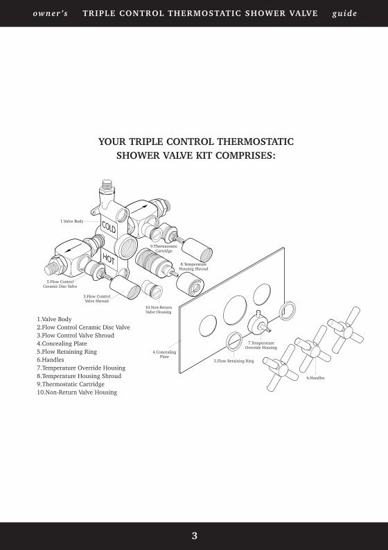
1.Valve Body
1.Valve Body2.Flow Control Ceramic Disc Valve3.Flow Control Valve Shroud4.Concealing Plate5.Flow Retaining Ring6.Handles7.Temperature Override Housing8.Temperature Housing Shroud9.Thermostatic Cartridge10.Non-Return Valve Housing
4.ConcealingPlate
5.Flow Retaining Ring
6.Handles
7.TemperatureOverride Housing
8.TemperatureHousing Shroud
9.ThermostaticCartridge
10.Non-ReturnValve Housing
2.Flow ControlCeramic Disc Valve
3.Flow ControlValve Shroud
YOUR TRIPLE CONTROL THERMOSTATIC SHOWER VALVE KIT COMPRISES:
owner’s TRIPLE CONTROL THERMOSTATIC SHOWER VALVE guide
TRIPLE Thermo US06 5/9/06 9:58 am Page 4

4
STEP BY STEP INSTALLATION GUIDE
PRE INSTALLATION NOTES
• Identify and check all the parts (shower control handles and
concealing plate styles may differ depending on model).
• When positioning the valve, ensure you have sufficient pressure for an
acceptable shower.
• The hot water feed must always be connected to the inlet marked HOT of
the shower valve.
• Both hot and cold supply feeds must have accessible isolator valves
fitted in-line for servicing purposes (not supplied).
• Refer to plumbing diagrams for further installation guidelines.
• Ensure that, after fitting the concealed valve, the area around the valve
is left clear and free to allow access for servicing purposes in the future.
owner’s TRIPLE CONTROL THERMOSTATIC SHOWER VALVE guide
TRIPLE Thermo US06 5/9/06 9:58 am Page 5
5
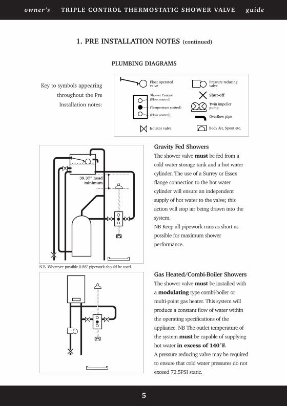
1. PRE INSTALLATION NOTES (continued)
PLUMBING DIAGRAMS
1 metre headminimum
Float operatedvalve
(Flow control)
(Temperature control)
Isolator valve
Pressure reducingvalve
Stop cock
Twin impellerpump
Overflow pipe(Flow control)
Shower Control
Body Jet, Spout etc.
Key to symbols appearing
throughout the Pre
Installation notes:
Gas Heated/Combi-Boiler ShowersThe shower valve must be installed with
a modulating type combi-boiler or
multi-point gas heater. This system will
produce a constant flow of water within
the operating specifications of the
appliance. NB The outlet temperature of
the system must be capable of supplying
hot water in excess of 140˚F.
A pressure reducing valve may be required
to ensure that cold water pressures do not
exceed 72.5PSI static.
Gravity Fed ShowersThe shower valve must be fed from a
cold water storage tank and a hot water
cylinder. The use of a Surrey or Essex
flange connection to the hot water
cylinder will ensure an independent
supply of hot water to the valve; this
action will stop air being drawn into the
system.
NB Keep all pipework runs as short as
possible for maximum shower
performance.
N.B. Wherever possible 0.86” pipework should be used.
owner’s TRIPLE CONTROL THERMOSTATIC SHOWER VALVE guide
Shut-off
39.37” headminimum
TRIPLE Thermo US06 5/9/06 9:58 am Page 6

6
1. PRE INSTALLATION NOTES (continued)
PLUMBING DIAGRAMS (continued)
Unvented Mains Pressure ShowersThe shower valve can be used on an
unvented mains pressure system. This
type of system must only be installed by
a competent person as per the
requirement of Part G of Schedule
1 to the building regulations.
For systems with no cold water take off
after the heaters pressure reducing valve,
an additional pressure reducing valve
must be fitted, and set, at the same
pressure as the heaters.
The water supply pressure to the shower
valve must be between 14.5 and 72.5 PSI.
Pumped ShowersThe shower valve can be used on a gravity
fed pumped system. The use of a Surrey
or Essex flange connection to the hot
water cylinder will ensure an independent
supply of hot water to the valve; this
action will stop air being drawn into the
system.
NB Please follow pump manufacturers’
instructions relating to the siting and
water feed details to the pump. Keep all
pipework runs as short as possible for
maximum shower performance.
N.B. Wherever possible 0.86” pipework
should be used to the pump. If non-return
valves are fitted to the pump you should
remove the ones from the valve inlets to
avoid cavitation.
owner’s TRIPLE CONTROL THERMOSTATIC SHOWER VALVE guide
TRIPLE Thermo US06 5/9/06 9:58 am Page 7

1. INSTALLATION INSTRUCTIONS
2. SITE PREPARATION
• Make a cavity in the wall to allow the hot and cold water supply and outlet
connections to be made.
• Both hot and cold supply feeds must be flushed through before connection
to the shower valve is made. Re: WRc byelaw 55.
• Please note: It is permissable to install the valve horizontally. Ensure the
hot supply is connected to the inlet marked HOT. Adjust the cavity to suit
i.e. 8.66” maximum x 11.8” maximum becomes 11.8” maximum x 8.66”
maximum.
Maximum300mm
Depth55/75 mm
Connectionto Cold Supply
Connectionto Hot Supply
Maximum220mm
Outlet
Outlet
7
owner’s TRIPLE CONTROL THERMOSTATIC SHOWER VALVE guide
8.66”
11.8”
2.16”/2.95”
TRIPLE Thermo US06 5/9/06 9:58 am Page 8
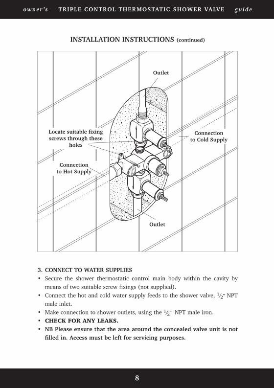
INSTALLATION INSTRUCTIONS (continued)
3. CONNECT TO WATER SUPPLIES• Secure the shower thermostatic control main body within the cavity by
means of two suitable screw fixings (not supplied).• Connect the hot and cold water supply feeds to the shower valve, 1/2” NPT
male inlet.• Make connection to shower outlets, using the 1/2” NPT male iron.• CHECK FOR ANY LEAKS.• NB Please ensure that the area around the concealed valve unit is not
filled in. Access must be left for servicing purposes.
Connectionto Cold Supply
Connectionto Hot Supply
Outlet
Outlet
Locate suitable fixingscrews through these
holes
8
owner’s TRIPLE CONTROL THERMOSTATIC SHOWER VALVE guide
TRIPLE Thermo US06 5/9/06 9:58 am Page 9

INSTALLATION INSTRUCTIONS (continued)
130mm
240mm
MinimumRecessSize
4. TILE UP/FINISH TO THE MINIMUM RECESS SIZE• This will allow for future servicing of the shower valve components.• Please note: If the valve is installed horizontally, the minimum recess size
changes from 5.1” x 9.45” to 9.45” x 5.1”.
5. FIT CONCEALING PLATE (Plate may differ in style depending on model)
• Remove ‘temperature override housing’ from thermostatic control. Note: Turn‘override button housing’ anti-clockwise until it stops against the preset100°F‘stop’.
• Locate concealing plate ‘grommet’ onto thermostatic control housing and fitconcealing plate to valve.
• Carefully refit ‘temperature override housing’ ensuring that the thermostaticcontrol spindle is not rotated (as this will alter the preset temperature). Note:Ensure that the override button is located against the preset 100°F stop.
• To create a waterseal, use a thin line of suitable sealant between the concealingplate and the wall.
9
owner’s TRIPLE CONTROL THERMOSTATIC SHOWER VALVE guide
5.1”
9.45”
TRIPLE Thermo US06 5/9/06 9:58 am Page 10
1 0
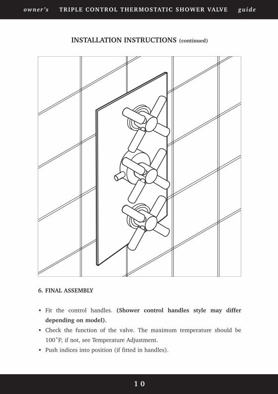
6. FINAL ASSEMBLY
Fit the control handles. (Shower control handles style may differ
depending on model).
Check the function of the valve. The maximum temperature should be
100˚F; if not, see Temperature Adjustment.
Push indices into position (if fitted in handles).
INSTALLATION INSTRUCTIONS (continued)
•
•
•
owner’s TRIPLE CONTROL THERMOSTATIC SHOWER VALVE guide
TRIPLE Thermo US06 5/9/06 9:58 am Page 11
1 1
TEMPERATURE ADJUSTMENT
The maximum temperature of the shower valve has been factory pre-set
at 100oF at the override position, if for any reason you wish to adjust
the maximum temperature, please follow these instructions:
Temperature adjustment - to increase the preset temperature to 38°C at theoverride position.
1. Set the shower anti-clockwise at the preset 100°F “stop” position
2. Ensure the shower is running
3. Press the override button and turn in small increments anti-clockwise to reach 38°C
at the shower outlet rose or handset.
Note: After each increment allow the valve temperature to stabilize for 10 seconds.
4. Carefully remove the handle and ‘temperature override housing’ ensuring that the
thermostatic control spindle is not rotated (as this will alter the preset temperature).
5. Carefully refit the temperature override housing and handle ensuring that the
thermostatic control spindle is not rotated (as this will alter the preset temperature).
Note: Ensure that the override button is located against the 100°F stop on the
temperature housing shroud.
Note: if the shower valve does not adjust to the 100°F minimum, this suggests a
problem with the incoming cold supply pressure. Please refer to the ‘Fault Finding
Chart’.
Temperature adjustment - to decrease the preset temperature to 100°F at the
override position.
• To decrease the temperature carry out the same procedure as above but with a
clockwise action.
owner’s TRIPLE CONTROL THERMOSTATIC SHOWER VALVE guide
TRIPLE Thermo US06 5/9/06 9:58 am Page 12

In accordance with our policy of ongoing product development, we reserve the right to change the specification of products and components.
If the Fault Finding chart does not remedy the problem,please contact the helpline immediately.
Telephone +44 (0)1282 446789.
GRAVITY or PUMPED SYSTEM
FAULT FINDING CHART
owner’s TRIPLE CONTROL THERMOSTATIC SHOWER VALVE guide
NB Any product guarantees will be invalidated if the internal workings of the valve have been tampered with in anyway.
Please call our HELPLINE if you are having any difficulties.
DIAGNOSIS
• Ensure hot water supply is at least 140ºF. • Make sure you have equal pressures. • Check for airlocks in pipework.• Ensure there are no inverted ‘U’s in any of the
pipework runs.
• Insufficient hot water storage
• Hot and cold supply connections have been madein reverse - reconnect correctly
• Turn down the flow of hot water from the pumpusing the in-line isolator valve.
FAULT
"Showering temperature is not hot enough"
"Water goes cold during shower"
"When shower is set at cold, theshowering temperature is too hot
"Shower temperature is too hot (pumped shower)"
COMBI or OTHER HIGH PRESSURE SYSTEM
DIAGNOSIS
• Incoming mains pressure exceeds 72.5PSI -ensure you have fitted a pressure reducing valvein the mains supply pipe.
• Ensure hot water supply is at least 140ºF.
• Incoming mains pressure exceeds 72.5PSI -ensure you have fitted a pressure reducing valvein the mains supply pipe immediately after shut-off to premises.
• Ensure the boiler is still firing. Adjust the boilerto the hottest output, not the best flow.
FAULT
"Showering temperature is not hot enough"
“Valve is very noisy when in use”
“The water goes cold whilst showering”
TRIPLE Thermo US06 5/9/06 9:58 am Page 1


![ROUSH CleanTech - Alternative Fuel Vehicles · CERT STD NMHC+NOx Imi US06 CO [g/mi] US06 CERT STD NMHC+NOx Imi SC03 CERT STD CERT STD Days Diurnal + Hot So (grams/test) @ UL Running](https://static.fdocuments.us/doc/165x107/6029e91bdce8f9707d7c9c89/roush-cleantech-alternative-fuel-vehicles-cert-std-nmhcnox-imi-us06-co-gmi.jpg)