
Trimble ASCII Interface Protocol (TAIP) - · PDF fileTrimble ASCII Interface Protocol T 1...
30
Trimble ASCII Interface Protocol T 1 Trimble ASCII Interface Protocol (TAIP) '1990-1998 Trimble Navigation Limited Trimble ASCII Interface Protocol (TAIP) is a Trimble-specified digital communication interface based on printable ASCII characters over a serial data link. TAIP was designed specifically for vehicle tracking applications but has become common in a number of other applications because of its ease of use. TAIP supports both scheduled and polled responses. TAIP messages may be scheduled for output at a user specified rate starting on a given epoch from top of the hour. For communication robustness, the protocol optionally supports checksums on all messages. It also provides the user with the option of tagging all messages with the unit’s user specified identification number (ID). This greatly enhances the functional capability of the unit in a network environment. Additionally, given the printable ASCII format of all communication, TAIP is ideal for use with mobile data terminals, seven bit modems and portable computers. Although, sensors incorporating this protocol are shipped from the factory with a specific serial port setting, the port characteristics are fully programmable through TAIP messages. This appendix is designed for easy reference to TAIP message formats and describes all the TAIP messages defined at the time of printing. Some of the defined TAIP messages are not supported by the SVeeSix receiver. The SVeeSix supports the following TAIP messages: SVeeSix Supported TAIP Messages AL Altitude/Vertical Velocity AP Auxiliary Port Characteristic CP Compact Position Solution DC Differential Corrections (DGPS ready units only) DD Delta Differential Corrections (DGPS ready units only) ID Vehicle ID IP Initial Position LN Long Navigation Message PT Port Characteristic PV Position/Velocity Solution RM Reporting Mode ST Status TM Time/Date VR Version Number
-
Upload
nguyenkhue -
Category
Documents
-
view
324 -
download
5
Transcript of Trimble ASCII Interface Protocol (TAIP) - · PDF fileTrimble ASCII Interface Protocol T 1...

Trimble ASCII Interface Protocol
T 1
Trimble ASCII Interface Protocol (TAIP)
©1990-1998 Trimble Navigation Limited
Trimble ASCII Interface Protocol (TAIP) is a Trimble-specified digital communicationinterface based on printable ASCII characters over a serial data link. TAIP wasdesigned specifically for vehicle tracking applications but has become common in anumber of other applications because of its ease of use. TAIP supports both scheduledand polled responses.
TAIP messages may be scheduled for output at a user specified rate starting on a givenepoch from top of the hour. For communication robustness, the protocol optionallysupports checksums on all messages. It also provides the user with the option of taggingall messages with the unit's user specified identification number (ID). This greatlyenhances the functional capability of the unit in a network environment.
Additionally, given the printable ASCII format of all communication, TAIP is ideal foruse with mobile data terminals, seven bit modems and portable computers. Although,sensors incorporating this protocol are shipped from the factory with a specific serialport setting, the port characteristics are fully programmable through TAIP messages.
This appendix is designed for easy reference to TAIP message formats and describes allthe TAIP messages defined at the time of printing. Some of the defined TAIP messagesare not supported by the SVeeSix receiver. The SVeeSix supports the following TAIPmessages:
SVeeSix Supported TAIP Messages
AL Altitude/Vertical Velocity
AP Auxiliary Port Characteristic
CP Compact Position Solution
DC Differential Corrections (DGPS ready units only)
DD Delta Differential Corrections (DGPS ready units only)
ID Vehicle ID
IP Initial Position
LN Long Navigation Message
P T Port Characteristic
PV Position/Velocity Solution
RM Reporting Mode
S T Status
TM Time/Date
VR Version Number

Trimble ASCII Interface Protocol
T 2
Message Format All TAIP communication uses printable, uppercase ASCIIcharacters. The interface provides the means to configure theunit to output various sentences in response to query or on ascheduled basis. Each sentence has the following generalformat:
>ABB{C}[;ID=DDDD][;* FF]<
where:> start of new message,A message qualifier,B B a two character message identifier,C data string,DDDD optional 4 character vehicle ID,FF optional 2 character checksum,< the delimiting character.
Notation:
{x} signifies that x can occur any number of times.[x] signifies that x may optionally occur once.
Start of new message The '>' character (ASCII code 62 decimal) is used to specify thestart of a new sentence.
Message Qualifier A one character message qualifier is used to describe the action to betaken on the message. The following table lists the validqualifiers:
Qualifier Action
Q Query for a single sentence (sent to GPS sensor).R Response to a query or a scheduled report (from the
sensor)F Schedule reporting frequency interval in secondsS Set command to download time to the GPS receiverD Specify a minimum distance traveled and a minimum
and maximum time interval for the next reportDetails on the use of message qualifiers are given in the last sectionof this appendix, Communication Using TAIP.
◆ NOTE: All TAIP message characters must be in uppercase.

Trimble ASCII Interface Protocol
T 3
Message Identifier A unique two character message identifier consisting of letters ofalphabet is used to identify different type messages.
Data String The format and length of the data string are dictated by themessage qualifier and the message identifier. It can consist of anyprintable ASCII character with the exception of the '>', '<', and ';'characters. A detailed descriptions of each message format is givenlater. Most messages are length sensitive and unless otherwisespecified, field separators including space are not used.
Vehicle ID A vehicle identification(ID) may optionally be used in all thecommunications with the sensor. Each sensor in the fleet may beassigned a four character alpha-numeric ID and be forced to outputthat ID in all messages. The default is: ID set to '0000' and the IDFlag set to 'F' (false).
The sensor will check all incoming messages for ID. If no ID isspecified, the sensor will accept the message. If the ID is includedin messages but does not compare with the ID previously set, themessage will be ignored. This applies even when the ID Flag isturned off.
Checksum The checksum field provides for an optional two digit hexchecksum value, which is computed as XOR of all characters fromthe beginning of the sentence up to and including the '*' character.If provided, the checksum is always the last element of thesentence before the message delimiter. The default mode ofoperation is to include checksum in sentences. The use of checksumscan help in instances where the communication channel is noisy.
Example The following message to set the vehicle ID flag on includeschecksum.
>SRM;ID_FLAG=T;*6F<
The checksum (6F) was generated by XOR'ing the ASCII codes for'>' and 'S' then XOR'ing that result with the ASCII code for 'R' andso forth, up to and including the '*' character.
Message Delimiter The '<' character signifies end of a sentence and is used as themessage delimiter.

Trimble ASCII Interface Protocol
T 4
Sample PV Message The Position/Velocity Solution (PV) message is one of the morecommonly used TAIP messages and most sensors using TAIP are setby default to output the PV message once every 5 seconds.
The following analysis of a typical PV message is provided tofurther explain the TAIP message protocol.
>RPV15714+3739438-1220384601512612 ; ID=1234 ; *7F<
Data String Optional
> R PV 15714 +3739438 -12203846 015 126 1 2 ;ID=1234 ;*7F <
Ending DelimiterChecksumVehicle IDAge of DataSource of DataHeadingSpeedLongitudeLatitudeGPS Time of DayPV MessageIdentifierResponseQualifierStarting Delimiter
Data String Information GPS Time of Day : 15714 seconds, 04:21:54 GPS (time of last fix)Latitude: +37.39438 degreesLongitude: -122.03846 degreesSpeed: 15 MPHHeading: 126 degreesSource of Data: 3D GPSAge of Data: Fresh (<10 seconds)
◆ NOTE: Refer to the discussion of the PV message data string for moredetail on how this message is interpreted.

Trimble ASCII Interface Protocol
T 5
Time and Distance Reporting
The "D" message qualifier allows you to specify a minimum distancetraveled as well as a minimum and maximum time interval for thenext report. Units that are stationed at a fixed location can beprogrammed to report only when the unit moves "off station" or aftera certain elapsed time since last report, but no more often than thespecified minimum time interval.
The message format used with the D qualifier is shown below:
>DAABBBBCCCCEEEEFFFF[;ID=GGGG][;*HH]<
ID Meaning > start of message delimiterD the Distance message qualifierAA message to report (i.e. PV means Position Velocity message)BBBB minimum time (seconds) interval between reports (Tinterval)
CCCC report epoch (number of seconds from top of the hour)EEEE delta distance (meters) from last reported distanceFFFF maximum time (seconds) interval between reports (Tmax)
GGGG optional vehicle identification number (user selected)HH optional checksum < End of message delimiter
◆ Note that if BBBB = 0, then the message output is disabled. IfFFFF = 0, maximum time feature is disabled (the unit will only reportif current position is greater than or equal to the delta distancespecified in EEEE).
For example, when the message: >DPV0030000505000900;ID=0105< issent to the GPS receiver, it specifies that vehicle number 105 (GGGG =0105) is to report the Position Velocity message (AA = PV) wheneverits current position differs from the previously reported position by atleast 500 meters (EEEE = 0500), but no more often than every 30 seconds(BBBB = 0030) or less often than every 15 minutes (FFFF = 0900seconds). The minimum and maximum time-out reports are to beissued with a 5 second offset (CCCC = 0005) from the top of the hour.The optional checksum was not used in this example. The squarebrackets, [. . .], shown in the format description above are used toindicate optional data. The brackets themselves are never includedin the actual TAIP message string.

Trimble ASCII Interface Protocol
T 6
Latitude and Longitude Conversion
The TAIP protocol reports latitude as positive north decimaldegrees and longitude as positive east decimal degrees, using theWGS-84 datum. For your application, you may wish to convert todegrees, minutes and seconds. The following example illustratesthe conversion of decimal degrees to degrees, minutes and seconds.
Example Given latitude and longitude in decimal degrees,
Latitude: +37.39438 degrees
Longitude: -122.03846 degrees
Convert latitude by multiplying the decimal fraction of degrees by60 to convert to minutes,
0.39438 x 60 = 23.6628 minutes
Retain the integer (23) portion as the minutes then multiply thedecimal fraction by 60 to convert to seconds,
0.6628 x 60 = 39.768 seconds
Since the sign of the latitude in this example is positive the resultis:
Latitude: N 37o 23' 39.77"
The longitude is converted in the same fashion:
Longitude: W 122o 02' 18.46"
◆ NOTE: at the earth's equator, one degree of latitude and longituderepresents 68.7 miles; therefore, 0.00001 degrees representsapproximately 3.6 feet or 1.1 meters. Each second representsapproximately 100.76 ft (30.7 m).

Trimble ASCII Interface Protocol
T 7
Message Data Strings The following table lists all the TAIP messages currently definedand comments regarding their application:
MessageIdentifier Message Name C o m m e n t s
AL Altitude/Vertical VelocityAM Alarm Placer™ GPS/DR onlyAP Auxiliary Port Characteristic dual port units onlyCP Compact Position SolutionDC Differential Corrections DGPS units onlyDD Delta Differential Corrections DGPS units onlyID Vehicle IDIP Initial PositionLN Long Navigation MessageP T Port CharacteristicPV Position/Velocity SolutionRM Reporting ModeS T StatusTM Time/DateVR Version NumberX1 Extended Diagnostics Message 1 Placer™ GPS/DR only
The data string format of each message is described in thefollowing pages.
◆ NOTES: Your Trimble GPS sensor may not support all the messagetypes. Please refer to page 1 of this appendix for a list of the messagesyour sensor supports.
All TAIP message characters must be in uppercase.

Trimble ASCII Interface Protocol
T 8
A L Altitude/Up Velocity
Data String Format:
AAAAABBBBBBCCCCDE
Item # of Char UNITS Format (Value)
GPS Time of day 5 Sec AAAAAAltitude 6 Meters BBBBBBVertical Velocity 4 MPH CCCCSource 1 n/a D (0 = 2D GPS)
(1 = 3D GPS)(2 = 2D DGPS)(3 = 3D DGPS)(6 = DR)(8 = Degraded DR)(9 = Unknown)
Age of Data Indicator 1 n/a E (2 = Fresh, <10 sec)(1 = Old, ≥10 sec)(0 = Not available)
Total 17
Altitude is above mean sea level in WGS-84. The GPS time ofday is the time of fix rounded to the nearest second. Thismessage contains data obtained from the last 3 dimensional fixand my not be current.
◆ NOTE: The data in this message is to be considered invalid andshould not be used, if the "Age of Data Indicator" is equal to 0(signifying data not available).

Trimble ASCII Interface Protocol
T 9
A M AlarmData String Format:
AAAAABBBCCCCCDDDDEEEEEFFFGGGHIJKK{L}
Item # of Char UNITS Format (Value) GPS Time of day 5 Sec AAAAALatitude 8 Deg BBB.CCCCCLongitude 9 Deg DDDD.EEEEESpeed 3 MPH FFFHeading 3 Deg GGGAlarm Code 1 n/a H (U =User generated)Source 1 n/a I (0 = 2D GPS)
(1 = 3D GPS)(2 = 2D DGPS)(3 = 3D DGPS)(6 = DR)(8 = Degraded DR)(9 = Unknown)
Age of Data Indicator 1 n/a J (2 = Fresh, <10 sec)(1 = Old, ≥10 sec)(0 = Not available)
Length ofOptional String (n) 2 n/a K K
Optional String n n/a {L} Total 33 + Length of Optional String
This message is generated when an alarm condition is present. TheAlarm Code indicates the reason for the generated alarm message.The frequency of the message output is system dependent. In somesystems, once an alarm condition is present, this message is outputperiodically until the alarm is "acknowledged" by sending the unitthe appropriate frequency message, setting the frequency of outputfor AM to zero (>FAM000<).
Position is in latitude (positive north) and longitude (positive east)WGS-84. Heading is in degrees from True North increasingeastwardly. The 'GPS time of day' is the time of fix rounded to thenearest second.
◆ NOTE: The AM message applies only to the Placer GPS/DR sensor.The SVeeSix does not support the AM message.

Trimble ASCII Interface Protocol
T 10
A P Auxiliary Port Characteristic
Data String Format:
AAAA,B,C,D,E,F
Item # of Char UNITS Format (Value)
Baud Rate 4 n/a AAAA (9600, 4800, 2400, 1200, or 0300)
# of data bits 1 n/a B (7 or 8)# of stop bits 1 n/a C (1 or 2)Parity 1 n/a D (N = None)
(O = Odd)(E = Even)
Auxiliary Port Number 1 n/a E ( 1 )Reserved 1 n/a F ( 0 )
Total 14 (including commas)
This message defines the characteristics for the auxiliary port.The auxiliary port is usually the RTCM input port on differentialready sensors.
The default settings of the auxiliary port are 1200 baud, 8 data bits,parity none, and 1 stop bit.
Example The following command will set the auxiliary port characteristicsto 2400 baud, 8 data bits, 1 stop bit and no parity.
>SAP2400,8,1,N,1,0<||_______ Note the inclusion of '0' in the
reserved field◆ NOTES: The AP command applies only to receivers with dual serial
ports.The SVeeSix is a single port module and does not support the APcommand.The AP command requires commas between data fields.

Trimble ASCII Interface Protocol
T 11
CP Compact Position Solution
Data String Format:
AAAAABBBCCCCDDDDEEEEFG
Item # of Char UNITS Format (Value)
GPS Time of day 5 Sec AAAAALatitude 7 Deg BBB.CCCCLongitude 8 Deg DDDD.EEEESource 1 n/a F (0 = 2D GPS)
(1 = 3D GPS)(2 = 2D DGPS)(3 = 3D DGPS)(6 = DR)(8 = Degraded DR)(9 = Unknown)
Age of Data Indicator 1 n/a G (2 = Fresh, <10 sec)(1 = Old, ≥10 sec)(0 = Not available)
Total 22
Position is in latitude (positive north) and longitude (positive east)WGS-84. The GPS time of day is the time of fix rounded to thenearest second.
◆ NOTE: The data in this message is to be considered invalid andshould not be used, if the "Age of Data Indicator" is equal to 0(signifying data not available).

Trimble ASCII Interface Protocol
T 12
DC Differential Corrections
This message provides the sensor with differential corrections fromRTCM-104 record types 1 and 9. The values are numerical valueswritten out in hex format, thus for each byte of data there is a twodigit hex number.
The format of the data string is as follows:
AAAABBCC{DDEEEEFFGG}
Item # of Char Type UNITS Format
Modified Z-count 4 WORD .6 sec AAAAStation health 2 BYTE n/a B BNumber of SVs 2 BYTE n/a CC
The next 5 bytes (10 characters) are repeated for each SVSV PRN & health
(UDRE) 2 BYTE n/a DDRange Correction 4 WORD RTCM-104 EEEERange-rate correction 2 BYTE RTCM-104 FFIODE 2 BYTE n/a GG
The units and scale factors are as defined by RTCM-104 version 1.The SV PRN and health contains the SV PRN in the lower 5 bitsand the health/UDRE/scale factor in the upper 3 bits. Rangecorrections are scaled by 0.02 meters times 2 raised to the "health"power. Range-rate corrections are scaled by 0.002 meters per secondtimes 2 raised to the "health" power.
◆ NOTES: The DC and DD TAIP messages described herein apply onlyto differential ready sensors and are provided to enclose differentialcorrections within the TAIP format. Most differential ready SVeeSixfamily sensors are also equipped with an auxiliary port to receiveRTCM-104 formatted differential corrections directly.Use of DC and DD messages to input corrections requires only onecommunications channel. Use of the auxiliary port to input RTCM-104 corrections assumes a separate communications channel isavailable for broadcast and receipt of differential corrections.The TAIP software toolkit, GPSSK, does not support DC and DDmessages.

Trimble ASCII Interface Protocol
T 13
DD Delta Differential Corrections
This message provides the sensor with delta differentialcorrections from RTCM-104 record type 2. The values are numericalvalues written out in hex format, thus for each byte of data there isa two digit hex number.
The format of the data string is as follows:
AAAABB{CCDDDD}
Item # of Char Type UNITS Format
Modified Z-count 4 WORD .6 sec AAAANumber of SVs 2 BYTE n/a B B
The next 3 bytes (6 characters) are repeated for each SVSV PRN 2 BYTE n/a CCDelta Range Correction 4 WORD RTCM-104 DDDD
The units and scale factors are as defined by RTCM-104 version 1.The health/UDRE/scale factor given for the specific SV in themost recent message "DC" is used. Delta range corrections arescaled by 0.02 meters times 2 raised to the "health" power.
◆ NOTES: The DC and DD TAIP messages described herein apply onlyto differential ready sensors and are provided to enclose differentialcorrections within the TAIP format. Most differential ready SVeeSixfamily sensors are also equipped with an auxiliary port to receiveRTCM-104 formatted differential corrections directly.
Use of DC and DD messages to input corrections requires only onecommunications channel. Use of the auxiliary port to input RTCM-104 corrections assumes a separate communications channel isavailable for broadcast and receipt of differential corrections.
The TAIP software toolkit, GPSSK, does not support DC and DDmessages.

Trimble ASCII Interface Protocol
T 14
ID Identification Number
Data String Format:
AAAA
Item # of Char UNITS Format
Vehicle ID 4 n/a AAAA
Total 4
This message is used to report or set the vehicle's (or sensor's)unique, four character, alpha-numeric, user assigned ID. Thedefault at cold start is '0000'.
Example The following message will set the vehicle ID to 101.
>SID0101<
The following is simply a response to a query for vehicle ID.
>RID0101<
◆ NOTE: The sensor will always check incoming messages for ID andcompare with the vehicle ID set in the sensor's memory. If no ID isincluded in the message, the sensor will assume a match and accept themessage. If the message sent to the sensor does contain a vehicle IDbut that ID does not match the ID previously set in the sensor, themessage will be ignored. This process is followed even when theID_Flag is turned off (refer to the message RM).

Trimble ASCII Interface Protocol
T 15
IP Initial Position
Data String Format:
AAABBBBCCCCC
Item # of Char UNITS Format
Initial Latitude 3 Deg AAAInitial Longitude 4 Deg BBBBInitial Altitude 5 10 Meters CCCCC
Total 12
This is a very coarse initial position that the user can provide toaid the sensor in obtaining its first fix. This is specially usefulwith sensors that do not have non-volatile (Battery Backed-up)memory. In such cases, every time the unit is powered up, it goesthrough a complete cold-start and it has absolutely no knowledgeof where it is. Providing this message improves performance bydecreasing the time to first fix and enhances the accuracy of theinitial two dimensional navigation solutions by providing areference altitude. In case of units with non-volatile memory,sending this message is only helpful if the unit has moved morethan 1,000 miles since its previous fix. In either case, the sensor caninitialize itself appropriately without any data from the user; Itmerely requires more time.
◆ NOTE: For all the above values, the first character specifies the sign(+/-).
Example The following message will set the initial position to 37o North,122o West, altitude 10 meters.
>SIP+37-122+0001<

Trimble ASCII Interface Protocol
T 16
LN Long Navigation Message
Data String Format:
AAAAABBBCCCDDDDDDDEEEEFFFFFFFGGGGGGGHHIIIJKKKKLMMMNOO{PPQQ}RRRRRRRRRRST
Item # of Char UNITS Format (Value) GPS Time of day 8 Sec AAAAA.BBBLatitude 10 Deg CCC.DDDDDDDLongitude 11 Deg EEEE.FFFFFFFAltitude above MSL 9 Ft GGGGGGG.HHHorizontal Speed 4 MPH III.JVertical Speed 5 MPH KKKK.LHeading 4 Deg MMM.NNumber of SVs used 2 n/a OO
The following two entries (4 characters) are repeated for each SV used:SV Id 2 n/a PPIODE (2 digit hex) 2 n/a QQ
Reserved 10 n/a RRRRRRRRRRSource 1 n/a S (0 = 2D GPS)
(1 = 3D GPS)(2 = 2D DGPS)(3 = 3D DGPS)(6 = DR)(8 = Degraded DR)(9 = Unknown)
Age of Data Indicator 1 n/a T (2 = Fresh, <10 sec)(1 = Old, ≥10 sec)(0 = Not available)
Total 65 + (Number of SV's used times 4)
Position is in latitude (positive north) and longitude (positive east)WGS-84. Heading is in degrees from True North increasingeastwardly. The GPS time of day is the time of fix rounded to thenearest second.
◆ NOTE: The data in this message is to be considered invalid andshould not be used, if the "Age of Data Indicator" is equal to 0(signifying data not available).

Trimble ASCII Interface Protocol
T 17
PT Port Characteristic
Data String Format:
AAAA,B,C,D
Item # of Char UNITS Format (Value) Baud Rate 4 n/a AAAA (9600,
4800, 2400, 1200, or 0300)
# of data bits 1 n/a B (7 or 8)# of stop bits 1 n/a C (1 or 2)Parity 1 n/a D (N = None)
(O = Odd)(E = Even)
Total 10 (including commas)
This message defines the characteristics for the primary TAIP port.
Most TAIP using sensors use the following default portcharacteristics (consult the Installation and Operator's Manual):
4800 baud
8 data bits
1 stop bit
No parity
◆ NOTES: The characteristics set by this message will be stored in thesensor's memory. The SVeeSix family of sensors do not include aninternal battery but provide a battery back-up input line that may beused to retain memory when main power is removed.
If you do not use battery back-up, all port characteristics will reset tothe default after power is removed.
The PT command uses commas between data fields.

Trimble ASCII Interface Protocol
T 18
P V Position/Velocity Solution
Data String Format:
AAAAABBBCCCCCDDDDEEEEEFFFGGGHI
Item # of Char UNITS Format (Value)
GPS Time of day 5 Sec AAAAALatitude 8 Deg BBB.CCCCCLongitude 9 Deg DDDD.EEEEESpeed 3 MPH FFFHeading 3 Deg GGGSource 1 n/a H (0 = 2D GPS)
(1 = 3D GPS)(2 = 2D DGPS)(3 = 3D DGPS)(6 = DR)(8 = Degraded DR)(9 = Unknown)
Age of Data Indicator 1 n/a I (2 = Fresh, <10 sec)(1 = Old, ≥10 sec)(0 = Not available)
Total 30
Position is in latitude (positive north) and longitude (positive east)WGS-84. Heading is in degrees from True North increasingeastwardly. The GPS time of day is the time of fix rounded to thenearest second.
◆ NOTE: The data in this message is to be considered invalid andshould not be used, if the "Age of Data Indicator" is equal to 0(signifying data not available).
Trimble ASCII Interface Protocol
T 19
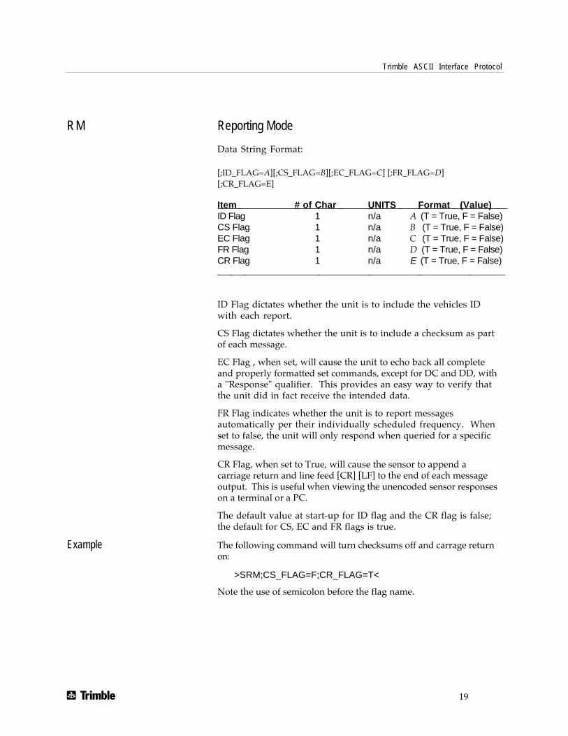
RM Reporting Mode
Data String Format:
[;ID_FLAG=A][;CS_FLAG=B][;EC_FLAG=C] [;FR_FLAG=D][;CR_FLAG=E]
Item # of Char UNITS Format (Value) ID Flag 1 n/a A (T = True, F = False)CS Flag 1 n/a B (T = True, F = False)EC Flag 1 n/a C (T = True, F = False)FR Flag 1 n/a D (T = True, F = False)CR Flag 1 n/a E (T = True, F = False)
ID Flag dictates whether the unit is to include the vehicles IDwith each report.
CS Flag dictates whether the unit is to include a checksum as partof each message.
EC Flag , when set, will cause the unit to echo back all completeand properly formatted set commands, except for DC and DD, witha "Response" qualifier. This provides an easy way to verify thatthe unit did in fact receive the intended data.
FR Flag indicates whether the unit is to report messagesautomatically per their individually scheduled frequency. Whenset to false, the unit will only respond when queried for a specificmessage.
CR Flag, when set to True, will cause the sensor to append acarriage return and line feed [CR] [LF] to the end of each messageoutput. This is useful when viewing the unencoded sensor responseson a terminal or a PC.
The default value at start-up for ID flag and the CR flag is false;the default for CS, EC and FR flags is true.
Example The following command will turn checksums off and carrage returnon:
>SRM;CS_FLAG=F;CR_FLAG=T<
Note the use of semicolon before the flag name.

Trimble ASCII Interface Protocol
T 20
ST Status
Data String Format:
AABCDDEFGG
◆ NOTE: This message provides information about the satellite trackingstatus and the operational health of the sensor. This information iscontained in five status bytes which are output as five 2 digithexadecimal values. The data format and the meanings of the hexcharacters are given in the following tables.
Item # of Char UNITS Format Tracking Status Code 2 n/a AA (see table below)Error Codes - Nibble 1 1 n/a B (see table below)Error Codes - Nibble 2 1 n/a C (see table below)Machine ID 2 n/a DDError Codes - Nibble 3 1 n/a E (not currently used)Error Codes - Nibble 4 1 n/a F (see table below)(reserved) 2 n/a GG (not currently used)
Value ofTracking Status Code AA Meaning
00 Doing position fixes01 Don't have GPS time yet02 Not used03 PDOP is too high08 No usable satellites09 Only 1 usable satellite0A Only 2 usable satellites0B Only 3 usable satellites0C 6-Ch units only: the chosen satellite is unusable.

Trimble ASCII Interface Protocol
T 21
ST Status (continued)◆ NOTE: In the tables below, an X in a column means that fault is being
reported.Error Codes – Nibble 1
Valueof B
Meaning
0 No Problems Reported1 X2 X3 X X
Antenna feedline fault (Note2)
Excessive ref freq error(Note 3)
Error Codes – Nibble 2Valueof C
Meaning
0 No Problems Reported1 X2 X3 X X4 X5 X X6 X X7 X X X8 X9 X XA X XB X X XC X X D X X XE X X XF X X X X
Battery back-up failed (Note1)
Signal Processor error (Note1)
Alignment error, channel orchip 1, (Note 1)
Alignment error, channel orchip 2, (Note 1)
Trimble ASCII Interface Protocol
T 22
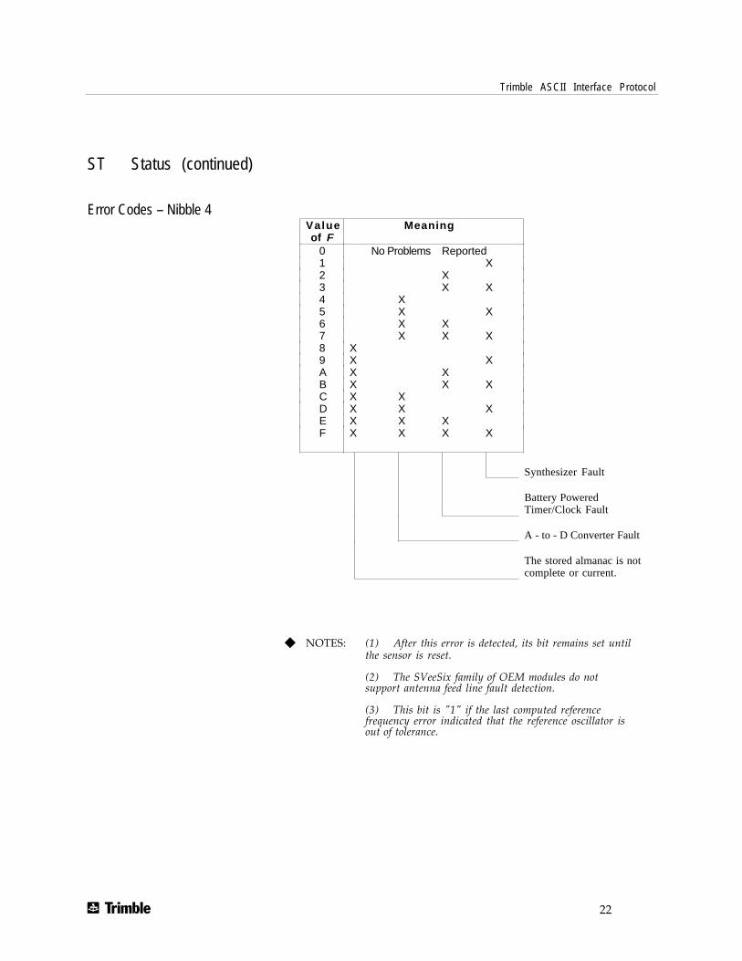
ST Status (continued)
Error Codes – Nibble 4Valueof F
Meaning
0 No Problems Reported1 X2 X3 X X4 X5 X X6 X X7 X X X8 X9 X XA X XB X X XC X XD X X XE X X XF X X X X
Synthesizer Fault
Battery PoweredTimer/Clock Fault
A - to - D Converter Fault
The stored almanac is notcomplete or current.
◆ NOTES: (1) After this error is detected, its bit remains set untilthe sensor is reset.
(2) The SVeeSix family of OEM modules do notsupport antenna feed line fault detection.
(3) This bit is "1" if the last computed referencefrequency error indicated that the reference oscillator isout of tolerance.

Trimble ASCII Interface Protocol
T 23
TM Time/Date
Data String Format:
AABBCCDDDEEFFGGGGHHIJJKLLLLL
Item # of Char UNITS Format (Value)
UTC Time of DayHours 2 Hour A AMinutes 2 Min B BSeconds 5 Sec CC.DDD
Date; Day 2 Day EEDate; Month 2 Month FFDate; Year 4 Year GGGGGPS/UTC Time Offset 2 Sec H HCurrent Fix Source 1 n/a I (0 = 2D GPS)
(1 = 3D GPS)(2 = 2D DGPS)(3 = 3D DGPS)(6 = DR)(8 = Degraded DR)(9 = Unknown)
Number of Usable SVs 2 n/a JJGPS/UTC Offset Flag 1 n/a K (1 = Valid)
(0 = Invalid)Reserved 5 n/a LLLLL
Total 28
This message outputs the time and date as computed by the GPSsensor. The time is most accurate when the unit is doing fixes. It isless accurate but still usable when the unit is not doing fixes but the'Number of Usable SVs' is one or more.
◆ NOTE: GPS/UTC Time Offset is the difference between GPS andUTC time standards in seconds. The 'UTC time of Day' is only validif the 'GPS/UTC Offset Valid Flag' is indicating valid.

Trimble ASCII Interface Protocol
T 24
TM Time/Date (continued)
The TM mesage is supported under the Set qualifier which allowsyou to download time to a GPS receiver that does not have a real-time clock. Fields AA through GGGG must be downloaded but theremaining fields may be filled with zeros (0) to create a total datastream of 28 characters. For warm-start performance, downloadedtime must only be accurate to ±5 minutes so the entire field may befilled with zeros. However if you wish to specify seconds, use aformat such as 08150 to represent 8.15 seconds. The reserved field,GGGGGGGGGGG, should be filled with zeros.
For example, when the >STM1925000002806199400000000000<message is sent to the GPS receiver, it specifies that the receivershould set its internal time to 19:25 (7:25 PM) UTC, 28 June 1994.The time downloaded to the receiver should be accurate to ±5minutes (use UTC, not local time) for optimum warm start or hotstart acquisition.

Trimble ASCII Interface Protocol
T 25
VR Version Number
Data String Format:
XXXXXXX ;VERSION A.AA(BB/BB/BB); CORE VERSION C.CC(DD/DD/DD); E
Item # of Char UNITS Format
Product Name n n/a n/aMajor Version number 4 n/a A.AAMajor Release Date 8 n/a BB/BB/BB
(month/day/year)Core Version number 4 n/a C.CCCore Release Date 8 n/a DD/DD/DD
(month/day/year)Copyright Text variable n/a
◆ NOTE: The length of this message is variable based upon copyrighttext string.
The phrase CoreVersion refers to the signal processing firmwareversion.

Trimble ASCII Interface Protocol
T 26
X1 Extended Diagnostics Message 1; Dead Reckoning
Data String Format:
,A,BC,DDDDDDD,EF,GG.GGGG,HH.HHHH,II.IIII
Item # of Char UNITS Format Diagnostics sub-
message ID 1 n/a AOdometer Status 1 1 n/a B (reserved)Odometer Status 2 1 n/a C (see table below)Odometer Scale Factor 7 Pulses/Mile DDDDDDDGyro Status 1 1 n/a E (reserved)Gyro Status 2 1 n/a F (see table below)Gyro Rate Bias 7 Deg/Sec GG.GGGGGyro Left Scale Factor 7 n/a HH.HHHHGyro Right Scale Factor 7 n/a II.IIII Total 40 (Including commas and decimal points)
◆ NOTE: The X1 message applies only to the Placer GPS/DR sensor.The SVeeSix does not support the X1 message.
Odometer Status 2Valueof C
Meaning
0 No Problems Reported1 X2 X3 X X4 X5 X X6 X X7 X X X
No pulses received fromodometer since start-up
Odometer scale factor is outof tolerance
Back-up light active

Trimble ASCII Interface Protocol
T 27
X1 Extended Diagnostics Message 1; Dead Reckoning (continued)
Gyro Status 2Valueof F
Meaning
0 No Problems Reported1 X2 X3 X X4 X5 X X6 X X7 X X X8 X9 X XA X XB X X XC X XD X X XE X X XF X X X X
Gyro hardware failedinternal diagnostics
Gyro bias is out of tolerance
Gyro scale factors out oftolerance
Gyro reference voltage isout of tolerance
Example An Odometer Status 2 value of '0' indicates no faults. An OdometerStatus 2 value of '4' simply indicates the backup light is active.An Odometer Status 2 value of '2' indicates the odometer scalefactor is out of tolerance.
Example A Gyro Status 2 value of '0' indicates no faults. A Gyro Status 2value of '5' indicates the gyro hardware failed the internaldiagnostics and that the scale factors are out of tolerance.
◆ NOTE: For more information on Dead Reckoning and the meaning ofterms used in this message, consult the Placer GPS/DR Installationand Operator's Manual.

Trimble ASCII Interface Protocol
T 28
Communication Using TAIPCommunication with the unit takes place in four different ways.Message qualifiers are used to differentiate between these.
Query for single sentence The query(Q) message qualifier is used to query the GPS sensor torespond immediately with a specific message. The format is:
>QAA[;ID=BBBB][;*CC]<
where AA is the requested message identifier. Messages supportedby this qualifier are AL, AM, AP, CP, ID, IP, LN, PT, PV, RM, ST,TM, VR, and X1.
Scheduled reporting frequency interval
The scheduled reporting frequency interval(F) message qualifier isused to tell the unit how often and when to report a specificmessage. The format is:
>FAABBBBCCCC[;ID=DDDD][;*FF]<
where sending this sentence tells the unit to report messagespecified by the two digit identifier AA at the time interval ofBBBB seconds with time epoch at CCCC seconds from top of thehour. Specifying time interval of 0000 stops scheduled reporting ofthe message. The default is 0000 time interval for all messagesexcept PV. The output frequency for PV at cold-start is set at onceevery five seconds, zero seconds from top of the hour. Messagessupported by this qualifier are AL, AM, AP, CP, ID, IP, LN, PT, PV,RM, ST, TM, VR, and X1.
Note that what is specified by this qualifier is the timing of themessage output and may be different from the time tag of the datain the message.

Trimble ASCII Interface Protocol
T 29
Communication Using TAIP (continued)
The Response to query or scheduled report
The response(R) qualifier carry various types of data between theunit and the user equipment. The format is:
>RAA[{B}][;ID=CCCC][;*DD]<
where AA is the two character message identifier and {B} specifiesthe data string within the message. For the format of {B}, pleaserefer to the message definitions in the previous section. Messagessupported by the response qualifier are AL, AM, AP, CP, ID, IP, LN,PT, PV, RM, ST, TM, VR, and X1.
The Set qualifier The set (S) qualifier enables the user equipment to initialize/set-up various types of data in the GPS unit. The format is:
>SAA[{B}][;ID=CCCC][;*DD]<
where AA is the two character message identifier and {B} specifiesthe data string within the message. For the format of {B}, pleaserefer to the message definitions in the previous section. Note thatall the messages have very specific formats and are lengthdependant. Messages normally supported by the set qualifier areAL, AP, CP, DC, DD, ID, IP, LN, PT, PV, RM and TM (the PlacerGPS/DR does not support the set qualifier for the AP message).
The set qualifier may be used with the AL, CP, LN, or PV messageto set more precise initial position data into the GPS sensor thancan be set with the IP message.

Trimble ASCII Interface Protocol
T 30
Communication Using TAIP (continued)
Sample Communication Session The following is a sample communication session to illustrate howmessage qualifiers are used. Query the sensor for version number forthe TAIP firmware:
>QVR<
The sensor responds with a message in the following form:
>RVR SVEESIX D;VERSION 4.06 (5/18/94); CORE VERSION 1.17(11/21/93); COPYRIGHT (C) 1991, 1992, 1993, 1994 TRIMBLENAVIGATION,LTD.;*32<
Notice that the sensor identified its product name, firmwareversion number, core signal processing version number, and releasedates, then included the checksum for the message (the default forthe CS Flag is TRUE). Also notice that the sensor did respond to ourquery even though we did not send a checksum.
Query the sensor for its ID number:
>QID<The sensor will respond (assuming factory default settings):
>RID0000;*70<Set the ID to match the number for a vehicle in your fleet and thentell the sensor to include the Vehicle ID in its responses:
>SID1234<
>SRM;ID_FLAG=T<Most Placer family sensors are set by default to report the PVmessage once every 5 seconds. (Note that the Placer GPS 400 IDreceiver automatically outputs the TAIP LN messages required forIND/IO operations.) To schedule the PV message from vehicle1234 to respond once every 10 seconds, starting at 5 seconds after thetop of the hour, use the following command:
>FPV00100005;ID=1234<The sensor will check the ID included in the message for a matchwith its own and then reschedule the PV message. At the nextscheduled time, the sensor will respond with:
>RPV15714+3739438-1220384601512612;ID=1234;*7F<Notice that the time given in the message is the time of the lastGPS fix (04:21:54 GPS), not necessarily the time of the messageresponse. If the time of last fix is 10 or more seconds old, the ageflag will be set to '1'.


