TRICON 3 Installation and Maintenance Guide
34
TRICON ® /E/E2/E3 Transmitter Installation and Maintenance Guide
Transcript of TRICON 3 Installation and Maintenance Guide

TRICON® /E/E2/E3 TransmitterInstallation andMaintenance Guide


TRICON® /E/E2/E3 TransmitterInstallation andMaintenance Guide

Copyright
This manual is an unpublished work and contains the trade secrets andconfidential information of Neptune Technology Group Inc., which are not to bedivulged to third parties and may not be reproduced or transmitted in whole orpart, in any form or by any means, electronic or mechanical for any purpose,without the express written permission of Neptune Technology Group Inc.All rights to designs or inventions disclosed herein, including the right tomanufacture, are reserved to Neptune Technology Group Inc.
The information contained in this document is subject to change without notice.Neptune reserves the right to change the product specifications at any timewithout incurring any obligations.
Trademarks Used in This Manual
The following are registered trademarks of Neptune Technology Group Inc.:
l E-CODERl E-CODER)R900il E-CODER)R450il ProCoderl ProCoder)R900il R900l TRICON
Other brands or product names are the trademarks or registered trademarks oftheir respective holders.
FCC Notice
This device complies with Part 15 of the FCC Rules. Operation is subject to thefollowing two conditions: (1) this devicemay not cause harmful interference, and(2) this devicemust accept any interference received, including interference thatmay cause undesired operation.
NOTE: This equipment has been tested and found to comply with the limits for aClass B digital device, pursuant to Part 15 of the FCC Rules. These limits aredesigned to provide reasonable protection against harmful interference in aresidential installation. This equipment generates, uses, and can radiate radiofrequency energy and, if not installed and used in accordance with theinstructions, may cause harmful interference to radio communications.However, there is no guarantee that interference will not occur in a particularinstallation. If this equipment does cause harmful interference to radio ortelevision reception, which can be determined by turning the equipment off andon, the user is encouraged to try to correct the interference by one or more ofthe following measures:

l Reorient or relocate the receiving antenna.l Increase the separation between the equipment and receiver.l Connect the equipment into an outlet on a circuit different from that to whichthe receiver is connected.
l Consult the dealer or an experienced radio / TV technician for help.
RF Exposure Information
This equipment complies with the FCC RF radiation requirements foruncontrolled environments. To maintain compliance with these requirements,the antenna and any radiating elements should be installed to ensure that aminimum separation distance of 20 cm is maintained from the generalpopulation.
Professional Installation
In accordance with section 15.203 of the FCC rules and regulations, theMIUmust be professionally installed by trained meter installers.
Changes or modifications not expressly approved by the party responsible forcompliance could void the user's authority to operate the equipment.
Industry Canada (IC) Statements
Section 8.4 of RSS-GEN
This device complies with Industry Canada License-exempt RSS standard(s).Operation is subject to the following two conditions:
l This devicemay not cause harmful interference.l This devicemust accept any interference received, including interference thatmay cause undesired operation.
Cet appareil est conforme aux normes RSS exonérées de licence d'IndustrieCanada. L'opération est soumise aux deux conditions suivantes: 1) cet appareilne doit pas provoquer d'interférence, et 2) cet appareil doit accepter touteinterférence, y compris les interférences pouvant entraîner un fonctionnementindésirable de l'appareil.
Section 8.3 of RSS-GEN
Under Industry Canada regulations, this radio transmitter may only operateusing an antenna of a type and maximum (or lesser) gain approved for thetransmitter by Industry Canada. To reduce potential radio interference to otherusers, the antenna type and its gain should be so chosen that the equivalentisotropically radiated power (e.i.r.p.) is notmore than that necessary forsuccessful communication.
This radio transmitter IC: 4171B-L900M has been approved by Industry Canadato operate with the antenna types listed below with themaximum permissible

gain and required antenna impedance for each antenna type indicated.Antenna types not included in this list, having a gain greater than themaximumgain indicated for that type, are strictly prohibited for use with this device.
l Maximum permissible gain of +1 dBi and required impedance of 75 ohm.l Approved Antenna types:
l R900® Pit Antenna, part number 12527-XXX.l High Gain R900® Pit Antenna, part number 13586-XXX.l R900®Wall Antenna, part number 13717-000.l Wiremonopole, part number 12641-XXX.
En vertu de la réglementation d'Industrie Canada, cet émetteur radio ne peutfonctionner qu'avec une antenne d'un type et un gain maximal (ou inférieur)approuvé pour l'émetteur par Industrie Canada. Pour réduire les interférencesradio potentielles avec d'autres utilisateurs, le type d'antenne et son gaindevraient être choisis demanière à ce que la puissance rayonnéeisotropiquement équivalente (e.i.r.p.) ne soit pas supérieure à celle nécessaire àune communication.
Cet émetteur radio IC: 4171B-L900M a été approuvé par Industrie Canada pourfonctionner avec les types d'antennes énumérés ci-dessous avec le gain maximaladmissible et l'impédance d'antenne requise pour chaque type d'antenneindiqué. Les types d'antenne non inclus dans cette liste, ayant un gain supérieurau gain maximal indiqué pour ce type, sont strictement interdits pour êtreutilisés avec ce périphérique.
l Gain maximal admissible de +1 dBi et impédance requise de 75 ohms.l Types d'antenne approuvé
l Antenne de puits R900®, numéro de pièce 12527-XXXl Antenne de puits à gain élevé R900®, référence 13586-XXXl Antennemurale R900®, numéro d'article 13717-00l Fil monopôle, numéro d'article 12641-XXX
TRICON® /E/E2/E3 TransmitterInstallation andMaintenance GuideLiterature No. IM TRICON /E/E2/E3 05.2020Part No. 13505-011
Neptune Technology Group Inc.1600 Alabama Highway 229Tallassee, AL 36078Tel: (800) 633-8754Fax: (334) 283-7293
Copyright © 2015 - 2020Neptune Technology Group Inc.
All Rights Reserved.

Contents
Chapter 1: Product Description 1
Transmitter Styles 1
Digital Pulse 1
Analog 4-20mA 1
Usage 2
Chapter 2: Specifications 3
3Environmental Conditions
Electrical Specifications (TRICON®/E3 Model) 3
Performance Data 5
Chapter 3: Installing the Transmitter 9
Tools and Materials 9
Preparation 9
Inspection and Storage 9
Safety and Preliminary Checks 9
Installation 10
Wiring the Transmitter 10
Testing theWires 13
Final Assembly 13
Mounting the Transmitter 13
Chapter 4: Maintaining the TRICON® System 15
Troubleshooting 15
Contact Information 15
By Phone 15
By Email 16
Glossary 17
Index 19
TRICON® E/E2/E3 Installation and Maintenance Guide vii

This page intentionally left blank.
viii TRICON® E/E2/E3 Installation and Maintenance Guide
Contents

Figures
10
11
11
11
12
Figure 1 – Transmitter Elements
Figure 2 – Elements of the Transmitter
Figure 3 – Creating a Hook in the Wire
Figure 4 – Connecting the Conductors
Figure 5 – TRICON®/E/E2/E3 Wiring
Figure 6 – Mounting the TRICON® Transmitter 14
TRICON® E/E2/E3 Installation and Maintenance Guide ix

This page intentionally left blank.
x TRICON® E/E2/E3 Installation and Maintenance Guide
Figures

Tables
3
4
4
5
5
6
6
7
8
8
12
Table 1 – Pulse Outputs (over 0-70° C Operating Temperature)
Table 2 – 4-20mA Model (Over 0-50° C Operating Temperature )
Table 3 – HF and UP / DN Models (Over 0-70° C Operating Temperature)
Table 4 – All Models Absolute Limits*
Table 5 – T-10® Disc Meters
Table 6 – T-8 Disc Meters
Table 7 – Trident® Turbine (TT) Meters
Table 8 – High Performance Turbine (HPT) Meters
Table 9 – Compound Meters
Table 10 – 4”, 6”, 8”, and 10” HP PROTECTUS® III Turbine Elements Performance Specifications
Table 11 – TRICON® E/E2/E3 Wiring Codes
Table 12 – Troubleshooting the TRICON® 15
TRICON® E/E2/E3 Installation and Maintenance Guide xi

This page intentionally left blank.
xii TRICON® E/E2/E3 Installation and Maintenance Guide
Tables
TRICON® E/E2/E3 Installation and Maintenance Guide 1
Chapter 1: Product Description
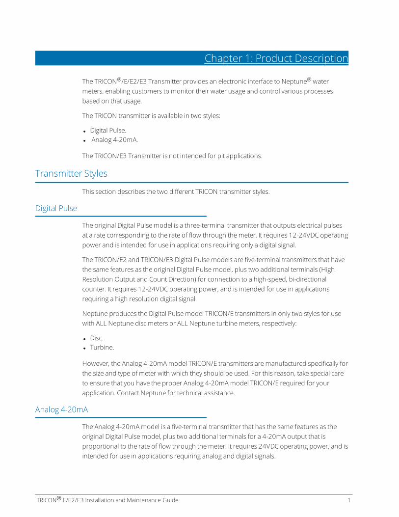
The TRICON®/E/E2/E3 Transmitter provides an electronic interface to Neptune®watermeters, enabling customers to monitor their water usage and control various processesbased on that usage.
The TRICON transmitter is available in two styles:
l Digital Pulse.l Analog 4-20mA.
The TRICON/E3 Transmitter is not intended for pit applications.
Transmitter Styles
This section describes the two different TRICON transmitter styles.
Digital Pulse
The original Digital Pulsemodel is a three-terminal transmitter that outputs electrical pulsesat a rate corresponding to the rate of flow through themeter. It requires 12-24VDC operatingpower and is intended for use in applications requiring only a digital signal.
The TRICON/E2 and TRICON/E3 Digital Pulsemodels are five-terminal transmitters that havethe same features as the original Digital Pulsemodel, plus two additional terminals (HighResolution Output and Count Direction) for connection to a high-speed, bi-directionalcounter. It requires 12-24VDC operating power, and is intended for use in applicationsrequiring a high resolution digital signal.
Neptune produces the Digital Pulsemodel TRICON/E transmitters in only two styles for usewith ALL Neptune disc meters or ALL Neptune turbinemeters, respectively:
l Disc.l Turbine.
However, the Analog 4-20mAmodel TRICON/E transmitters aremanufactured specifically forthe size and type of meter with which they should be used. For this reason, take special careto ensure that you have the proper Analog 4-20mAmodel TRICON/E required for yourapplication. Contact Neptune for technical assistance.
Analog 4-20mA
The Analog 4-20mAmodel is a five-terminal transmitter that has the same features as theoriginal Digital Pulsemodel, plus two additional terminals for a 4-20mA output that isproportional to the rate of flow through themeter. It requires 24VDC operating power, and isintended for use in applications requiring analog and digital signals.

Usage
All TRICON transmitter models are designed to bemounted between themeter maincaseand a totalizing register, and they do not affect the normal operation of either themeter orthe register. When used with a SmartTrol® controller or other third-party instrumentationequipment, both the Digital Pulse and Analog models allow monitoring and controllingcomplex metering systems.
2 TRICON® E/E2/E3 Installation and Maintenance Guide
Chapter 1: Product Description
TRICON® E/E2/E3 Installation and Maintenance Guide 3
Chapter 2: Specifications
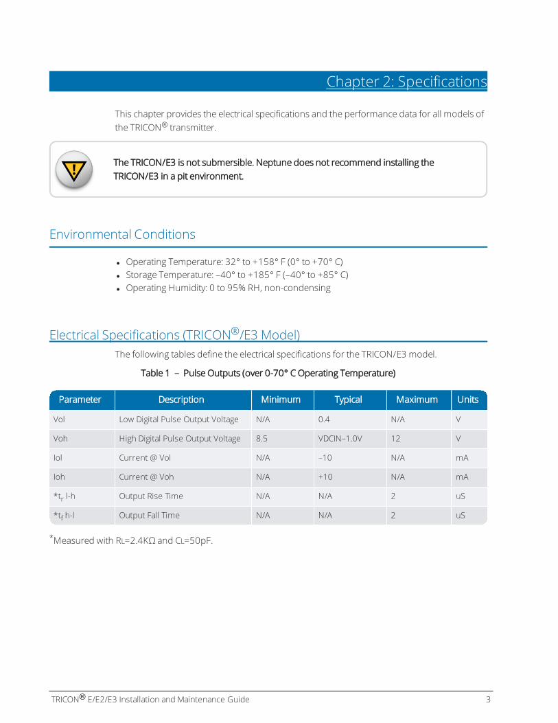
This chapter provides the electrical specifications and the performance data for all models ofthe TRICON® transmitter.
The TRICON/E3 is not submersible. Neptune does not recommend installing theTRICON/E3 in a pit environment.
Environmental Conditions
l Operating Temperature: 32° to +158° F (0° to +70° C)l Storage Temperature: –40° to +185° F (–40° to +85° C)l Operating Humidity: 0 to 95% RH, non-condensing
Electrical Specifications (TRICON®/E3 Model)The following tables define the electrical specifications for the TRICON/E3 model.
Parameter Description Minimum Typical Maximum Units
Vol Low Digital Pulse Output Voltage N/A 0.4 N/A V
Voh High Digital Pulse Output Voltage 8.5 VDCIN–1.0V 12 V
Iol Current @ Vol N/A –10 N/A mA
Ioh Current @ Voh N/A +10 N/A mA
*tr l-h Output Rise Time N/A N/A 2 uS
*tf h-l Output Fall Time N/A N/A 2 uS
Table 1 – Pulse Outputs (over 0-70° C Operating Temperature)
*Measured with RL=2.4KΩ and CL=50pF.

Parameter Description Minimum Typical Maximum Units
Vcc Power Supply Voltage 22.5 N/A 26.5 V
IS Power Supply Current 20 N/A 80 mA
RL Loop Resistance 0 N/A 600 Ω
Gain Scaling Accuracy N/A N/A 0.5 %FS
Zero Offset Accuracy N/A N/A 0.2 %FS
Vol Low Digital Pulse Output Voltage N/A 0.4 N/A V
Voh High Digital Pulse Output Voltage 8.5 N/A 12 V
Iol Current @ Vol N/A –10 N/A mA
Ioh Current @ Voh N/A 10 N/A mA
*tr l-h Output Rise Time N/A N/A 2 uS
*tf h-l Output Fall Time N/A N/A 2 uS
Table 2 – 4-20mAModel (Over 0-50° C Operating Temperature )
*Measured with RL=2.4KΩ and CL=50pF
Parameter Description Minimum Typical Maximum Units
Vcc Power Supply Voltage 11.5 N/A 26.5 V
IS Power Supply Current 20 N/A 50 mA
Vol Low Digital Pulse OutputVoltage
0 N/A N/A V
Voh High Digital Pulse OutputVoltage
N/A 24 26.5 V
Iol Current @ Vol –1.0 N/A N/A A
Ioh Current @ Voh N/A 0.04 +1.0 W/Voh A
*tr l-h Output Rise Time N/A N/A 2 uS
*tf h-l Output Fall Time N/A N/A 2 uS
Table 3 – HF and UP / DN Models (Over 0-70° C Operating Temperature)
*Measured with RL=2.4KΩ and CL=50pF
4 TRICON® E/E2/E3 Installation and Maintenance Guide
Chapter 2: Specifications

Parameter Description Minimum Maximum Units
T (op) Operating Temperature 0 85 °C
T (stg) Storage Temperature –40 85 °C
Vcc Power Supply Voltage –30 30 V
RL Output Load (pulse output) 1200 N/A KΩ
Iout Output Current (pulse output) N/A 10 mA
Table 4 – All Models Absolute Limits*
*These limits cannot be exceeded without possible damage.
Performance Data
The following tables define the performance data for all TRICON models.
MeterSize(In)
MaximumFlow Rate(gpm)
MaximumContinuous Flow
Rate (gpm)
MinimumFlow Rate(gpm)
Number ofPulses perGallon*
Pulse Output@ MaximumFlow Rate (Hz)*
Flow Range of4-20MA
Output (gpm)
⅝ 20 10 ¼ 578.10 192.70 0–20
¾ 30 15 ½ 322.60 161.30 0–30
1 50 25 ¾ 150.80 125.67 0–50
1½ 100 50 1½ 67.57 112.62 0–100
2 160 80 2 37.30 100.00 0–160
Table 5 – T-10® Disc Meters
*For the High Resolution Output of TRICON/E2 transmitters, multiply these values by 36, and for theTRICON/E3, multiply by 40.
TRICON® E/E2/E3 Installation and Maintenance Guide 5
Chapter 2: Specifications

MeterSize(In)
MaximumFlow Rate(gpm)
MaximumContinuousFlow Rate(gpm)
Minimum FlowRate (gpm)
Number ofPulses perGallon*
Pulse Output@Maximum Flow
Rate (Hz)*
Flow Range of 4-20MA Output
(gpm)
⅝ 20 10 ¼ 473.60 157.87 0–24.411
¾ 30 15 ½ 329.14 164.57 0–29.40
1 50 25 ¾ 126.55 105.46 0–59.581
1½ 100 50 1½ 47.86 79.77 0–141.181
2 160 80 2 25.60 68.27 0–234.371
Table 6 – T-8 Disc Meters
Meter Size (In)
MaximumContinuousFlow Rate(gpm)
MinimumFlow Rate(gpm)
Number ofPulses perGallon*
Pulse Output@Maximum Flow
Rate (Hz)*
Flow Range of4-20MA
Output (gpm)
2 200 3 4.6080 15.36 0–200
3 450 5 2.8900 21.68 0–450
4 1,000 10 1.5900 26.50 0–1,000
6 2,000 20 0.4640 15.47 0–2,000
8 (through S/N 31918014) 3,500 35 0.2493 14.54 0–3,500
8 (from S/N 31918274) 3,500 35 0.2253 13.14 0–3,873
10 (through S/N 31919282) 5,500 50 0.1600 14.67 0–5,500
10 (from S/N 31919300) 5,500 50 0.1472 13.49 0–5,981
*For the High Resolution Output of TRICON/E2 transmitters, multiply these values by 36, and for the TRICON/E3, multiply by 40.
1T-8 disc meters are no longer manufactured, so all TRICON/E transmitters manufactured for disc meters are the T-10 type. In most cases, the newer T-10 meter chamber is smaller than its corresponding T-8 meter chamber, which results in the TRICON/E having a theoretical “Flow Rate at 20mA Output” that is greater than the Maximum Flow Rate allowed for the meter. This means that the T-10 type TRICON/E running on aT-8 meter will never actually reach the 20mA output level during normal operation. The calculated flow rate required to produce a 20mA output is a reference for calibrating the 4-20mA receiving instrument.
Table 7 – Trident® Turbine (TT) Meters
*For the High Resolution Output of the TRICON/E2 transmitters, multiply these values by 9 and for theTRICON/E3, multiply these values by 10.
6 TRICON® E/E2/E3 Installation and Maintenance Guide
Chapter 2: Specifications

Meter Size (In)
MaximumContinuousFlow Rate(gpm)
Minimum FlowRate (gpm)
Number of Pulses perGallon*
Pulse Output@Maximum Flow
Rate (Hz)*
Flow Range of4-20MA
Output (gpm)
1½ 160 4 6.09500 16.25 0–160
2 200 4 6.09500 20.32 0–200
3 450 5 11.20000 84.00 0–450
4 1,200 10 7.55600 151.1 0–1,200
6 2,500 20 0.72730 30.30 0–3,000
8 4,000 35 0.75560 50.37 0–4,000
10 6,500 50 0.75560 81.86 0–6,500
12 8,000 120 0.75560 100.75 0–8,000
16 13,500 200 0.07556 17.00 0–13,500
20 22,000 300 0.07556 27.71 0–22,000
Table 8 – High Performance Turbine (HPT) Meters
*For the High Resolution Output of the TRICON/E2 transmitters, multiply these values by 9 and for theTRICON/E3, multiply these values by 10.
TRICON® E/E2/E3 Installation and Maintenance Guide 7
Chapter 2: Specifications

Compound Meter* Size and Type Turbine Element Disc Element
3” TRU/FLO 3” TT ⅝” T-10
4” TRU/FLO 4” TT ¾” T-10
6” TRU/FLO 6” TT T-10
2” HP TRU/FLO 2” HPT ⅝” T-10
4” PROTECTUS III 4” TT 1” T-10
6” PROTECTUS III 6” TT 1½” T-10
8” PROTECTUS III 8” TT 2” T-10
10” PROTECTUS III 10” TT 2” T-10
4” HP PROTECTUS III 1 1” T-10
6” HP PROTECTUS III 1 1½” T-10
8” HP PROTECTUS III 1 2” T-10
10” HP PROTECTUS III 1 2” T-10
Table 9 – Compound Meters
*For TRICON/E Performance Specifications of Compound Meters, refer to the specification information ofeach respective meter element.1Refer to the following table for the performance specifications of the 4”, 6”, 8”, and 10” HP PROTECTUS III
Turbine Elements.
Meter Size (In)Maximum Continuous
Flow Rate (gpm)Number of Pulses
per Gallon*
Pulse Output@Maximum Flow Rate
(Hz)1
Flow Range of4-20MA Output
(gpm)
4 1,200 7.5560 151.2 0–1,200
6 2,500 0.7556 37.78 0–2,888
8 4,000 0.6095 40.63 0–4,959
10 6,500 0.5333 57.78 0–9,209
Table 10 – 4”, 6”, 8”, and 10” HP PROTECTUS® III Turbine Elements Performance Specifications
*For the High Resolution Output of the TRICON/E2 transmitters, multiply these values by 9 and for theTRICON/E3, multiply these values by 10.
1Note: This table is based on mounting the HPT TRICON/E3 on the same size HP PROTECTUS III TurbineElement.
8 TRICON® E/E2/E3 Installation and Maintenance Guide
Chapter 2: Specifications

TRICON® E/E2/E3 Installation and Maintenance Guide 9
Chapter 3: Installing the Transmitter
This chapter is designed to take you through the installation process for the TRICON®
transmitter.
Tools andMaterials
The following equipment is required for the installation:
l Medium, flat-head screwdriver.l Wire stripper.l Hammer.l Small (⅛”) diameter punch, or similar tool.l Multi-conductor, solid, #22 American Wire Gauge (AWG), copper cable.l Dow Corning® #4, or equivalent compound (optional).
Some itemsmay not apply to your specific installation, or the list may not contain allrequired tools or materials.
Preparation
Be sure to review the following sections before beginning the installation.
Inspection and Storage
Remove the assembly parts from the parts bag and inspect them for any damage. Thetransmitter arrives partially assembled, with the terminal cover and mounting ring being theonly separate parts. After the inspection is complete, store the cartons in a clean, dryenvironment. The temperature should remain between –40° F and +185° F (–40° C and+85° C).
Safety and Preliminary Checks
Always follow your local electrical and safety codes and observe the following guidelines forrunning wire between your TRICON/E transmitter and the receiving device.
Avoid installing your TRICON E/E2/E3 instrumentation wiring near sources of electrical noise,such as:
l Contactors, motor starters, and relays.l Radio transmitters and antennas.l High-voltage power wiring and transformers.

l Whenever possible, separate your instrumentation wiring from other wiring by using aseparatemetal conduit or metal wire tray.
l Use theminimum length of cable required for the installation and cut off any excess. Donot coil excess wire.
For longer runs (maximum 1,000 feet) use #22 AWG shielded twisted pair cable for signalconnections, and tie the shield to the ground at the receiving device, not at the TRICON/Etransmitter.
l When forced to cross other wiring, cross at right angles to minimize noise couplingbetween wiring.
l Use a dedicated power source, such as a separate circuit breaker or isolation transformer,for all instrumentation equipment to reduce the effects of electrical noise from otherequipment on the line.
l Ensure proper earth ground is available and installed in compliance with local electricalcodes.
Installation
This section defines the procedures to install the TRICON transmitter.
Wiring the Transmitter
Follow this procedure to wire the transmitter.
1. Locate the terminal cover and remove the cover screw.2. Lift the terminal cover from the transmitter.
Figure 1 – Transmitter Elements
10 TRICON® E/E2/E3 Installation and Maintenance Guide
Chapter 3: Installing the Transmitter

3. Insert the end of themulti-conductor cable through the hole in the terminal cover asshown in the previous figure. Move the cover far enough down the cable to allow you towork with the end that you just inserted.
Figure 2 – Elements of the Transmitter
4. Strip the outer covering of the cable back approximately 1½” from the inserted end.5. Separate the individual conductors and strip the insulation back approximately ½” from
the end of each conductor.6. Using the rounded shaft of the screwdriver, form a hook in the end of each bare copper
wire.
Figure 3 – Creating a Hook in theWire
7. Loosen the terminal screws.
Figure 4 – Connecting the Conductors
8. Position the wire hook of each conductor under the proper terminal screw according tothe wiring diagram.
TRICON® E/E2/E3 Installation and Maintenance Guide 11
Chapter 3: Installing the Transmitter
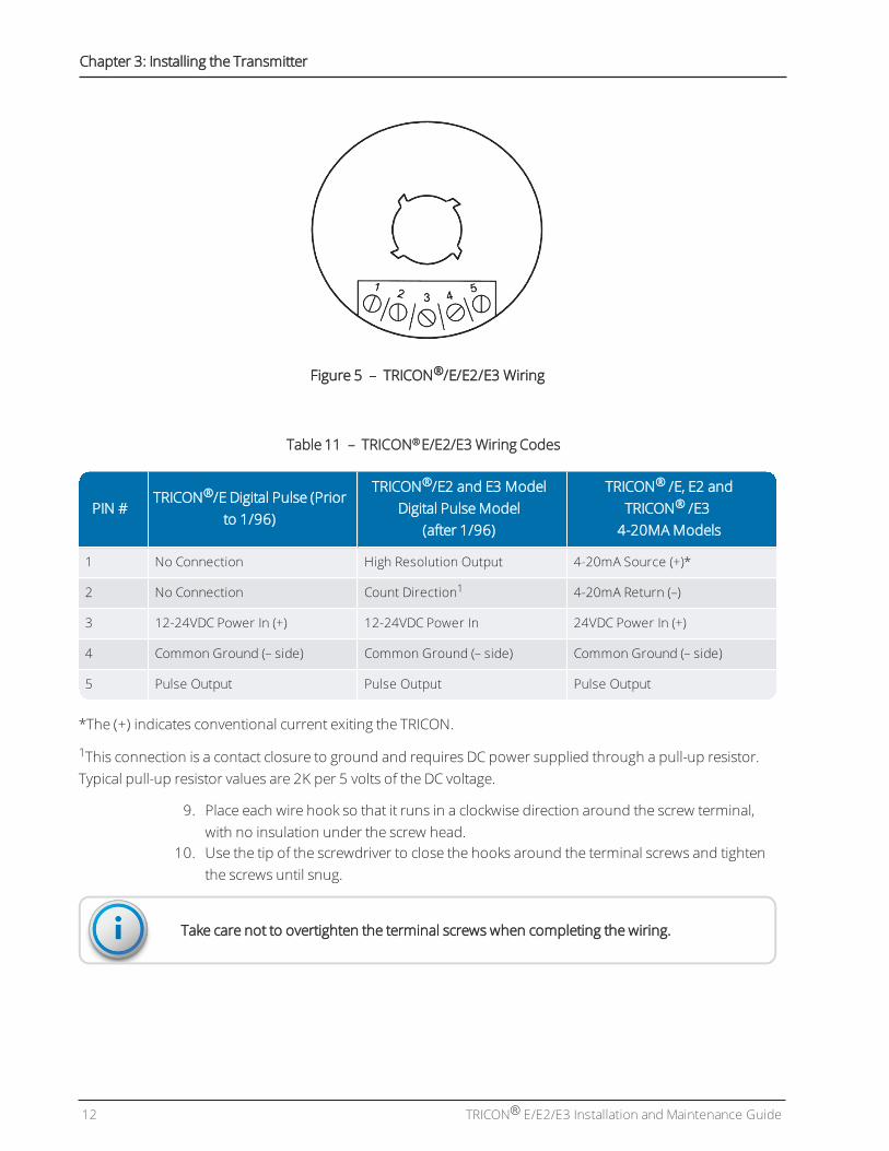
Figure 5 – TRICON®/E/E2/E3 Wiring
PIN #TRICON®/E Digital Pulse (Prior
to 1/96)
TRICON®/E2 and E3 ModelDigital Pulse Model
(after 1/96)
TRICON® /E, E2 andTRICON® /E34-20MAModels
1 No Connection High Resolution Output 4-20mA Source (+)*
2 No Connection Count Direction1 4-20mA Return (–)
3 12-24VDC Power In (+) 12-24VDC Power In 24VDC Power In (+)
4 Common Ground (– side) Common Ground (– side) Common Ground (– side)
5 Pulse Output Pulse Output Pulse Output
Table 11 – TRICON® E/E2/E3 Wiring Codes
*The (+) indicates conventional current exiting the TRICON.
1This connection is a contact closure to ground and requires DC power supplied through a pull-up resistor.Typical pull-up resistor values are 2K per 5 volts of the DC voltage.
9. Place each wire hook so that it runs in a clockwise direction around the screw terminal,with no insulation under the screw head.
10. Use the tip of the screwdriver to close the hooks around the terminal screws and tightenthe screws until snug.
Take care not to overtighten the terminal screws when completing the wiring.
12 TRICON® E/E2/E3 Installation and Maintenance Guide
Chapter 3: Installing the Transmitter

Testing the Wires
After wiring the transmitter, double-check to ensure it is wired correctly.
1. Apply power to the TRICON transmitter and check the output signals as follows:
l At No Flow – there should be no pulses out of the digital output terminal, and a 4mAdirect current should be present in the 4-20mA loop.
l At ½ Flow – the pulse rate out of the digital output terminal should be ½ themaximumpulse rate, and a 12mA direct current should be present in the 4-20mA loop.
l AtMaximum Flow – the pulse rate out of the digital output terminal should be equal tothemaximum pulse rate, and a 20mA direct current should be present in the 4-20mAloop.
Final Assembly
After testing is complete, the transmitter is ready for the final steps of the assembly process.
1. Shut off all power to the TRICON.2. Place a generous amount of Dow Corning #4 compound on all exposed wire and
terminals.3. Fill the inside of the terminal cover with themoisture compound.4. Slide the terminal cover in place over the terminal screws.5. Fasten the terminal cover with the cover screw and tighten until snug.
Take care not to overtighten the cover screw when securing the terminal cover.
6. Snap the strain relief fitting over the cable and push it into place in the cable entry hole.7. Wipe away any excess compound.
Mounting the Transmitter
After you assemble the transmitter, it is ready to bemounted. If you are installing a TRICONtransmitter on a meter that does not already have a register mounted on it, skip to step 4. Ifthemeter does have a register mounted, begin at step 1.
1. Position the small end of the punch on the center of the seal pin at the base of theregister.
2. Using the hammer, drive the punch through the center of the seal pin. The head of thepin should shear off.
TRICON® E/E2/E3 Installation and Maintenance Guide 13
Chapter 3: Installing the Transmitter
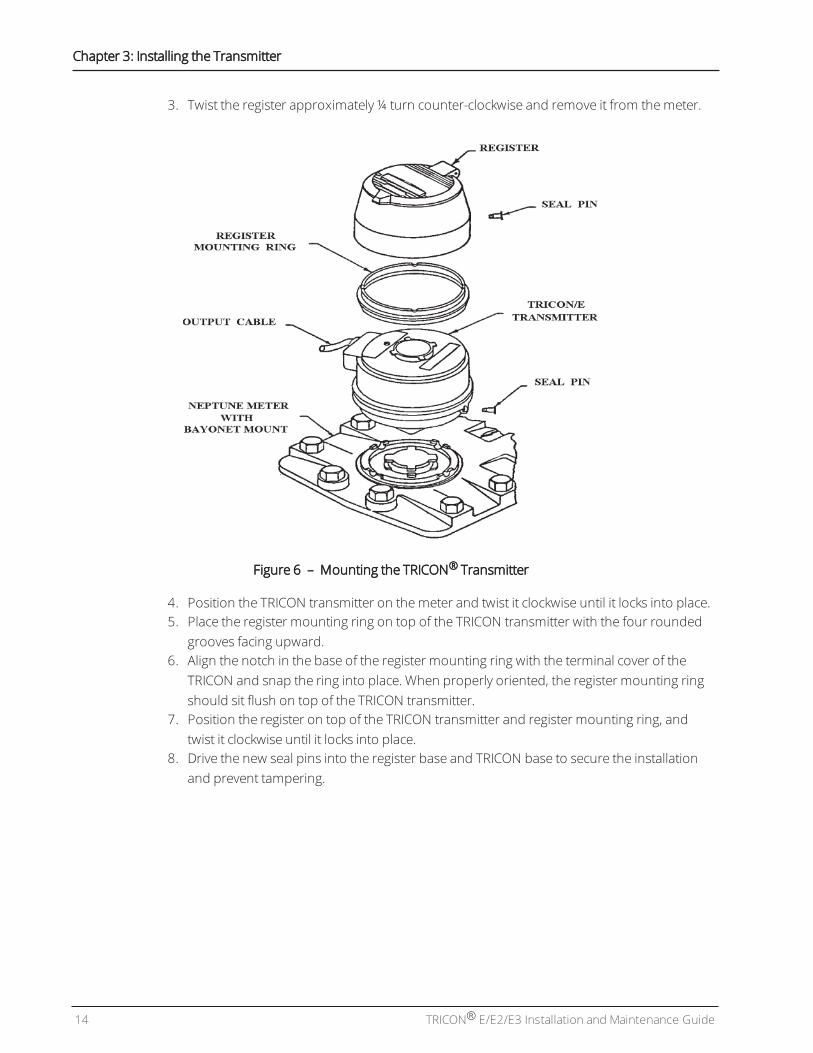
3. Twist the register approximately ¼ turn counter-clockwise and remove it from themeter.
Figure 6 – Mounting the TRICON® Transmitter
4. Position the TRICON transmitter on themeter and twist it clockwise until it locks into place.5. Place the register mounting ring on top of the TRICON transmitter with the four rounded
grooves facing upward.6. Align the notch in the base of the register mounting ring with the terminal cover of the
TRICON and snap the ring into place. When properly oriented, the register mounting ringshould sit flush on top of the TRICON transmitter.
7. Position the register on top of the TRICON transmitter and register mounting ring, andtwist it clockwise until it locks into place.
8. Drive the new seal pins into the register base and TRICON base to secure the installationand prevent tampering.
14 TRICON® E/E2/E3 Installation and Maintenance Guide
Chapter 3: Installing the Transmitter

TRICON® E/E2/E3 Installation and Maintenance Guide 15
Chapter 4: Maintaining the TRICON® System
If you find that your TRICON® system is not operating as expected when installed, use thefollowing guidelines to try to determine the source of the problem.
Troubleshooting
If the TRICON appears to be operating, but electronic flow indication does not agree withmechanical register indication, try the troubleshooting steps in the following table.
Verify that the... If not, then...
TRICON and register match the meter size and type. Replace the TRICON or the register with the appropriatetype to match the meter.
Register turns smoothly when installed on the TRICON. Replace the register or have it repaired to correctproblems with excessive torque.
TRICON is wired and powered properly. Correct the wiring or power problem.
Compatibility and proper calibration of equipment towhich the TRICON is connected.
Adjust and calibrate the equipment as required.
Table 12 – Troubleshooting the TRICON®
Contact Information
Within North America, Neptune Customer Support is available Monday through Friday,7:00 A.M. to 5:00 P.M. Central Standard Time, by telephone or email.
By Phone
To contact Neptune Customer Support by phone, complete the following steps.
1. Call (800) 647-4832.2. Select one of the following options:
l 1 if you have a Technical Support Personal Identification Number (PIN).l 2 if you do not have a Technical Support PIN.
3. Enter the six-digit PIN and press #.4. Select one of the following options.
l 2 for Technical Support.l 3 for maintenance contracts or renewals.l 4 for Return Material Authorization (RMA) for Canadian Accounts.

You are directed to the appropriate team of Customer Support Specialists. The specialists arededicated to you until the issue is resolved to your satisfaction. When you call, give thefollowing information:
l Your name and utility or company name.l A description of what occurred and what you were doing at the time.l A description of any actions taken to correct the issue.
By Email
To contact Neptune Support by email, send your message to [email protected].
16 TRICON® E/E2/E3 Installation and Maintenance Guide
Chapter 4: Maintaining the TRICON® System

Glossary
A
AWWA
American Water Works Association.
F
FCC
Federal Communications Commission.
flange
Ring or collar, usually provided with holes for bolts.
G
gasket
Piece of rubber or some other material that is used to make a tight seal between two parts thatare joined together.
H
HP
High Performance.
I
Imperial Gallon
Unit for measuring a volume of liquid or the capacity of a container for storing liquid, not themass of a liquid. One imperial gallon is equivalent to approximately 1.2 U.S. liquid gallons.
TRICON® E/E2/E3 Installation and Maintenance Guide 17

Glossary
P
PIN
Personal Identification Number.
PSI
Pounds per square inch.
R
RMA
Return Material Authorization.
S
strainer
Mesh barrier protecting themeter from debris in the line and corrects the velocity profile of the flowto themeter.
U
U.S Gallon
U.S. liquid gallon is defined as 231 cubic inches and equates to approximately 3.785 litres.
UL
Underwriters Laboratory.
UME
Unitized Measuring Element.
18 TRICON® E/E2/E3 Installation and Maintenance Guide

A
absolute limits 5
Analog 4-20mA 1
assembly, final 13
C
calibration issues 15
compound meters 8
conditions, environmental 3
conductors 11
Customer Support 15
D
data, performance 5
Disc 1
E
electrical noise 9
F
five-terminal transmitters 1
H
HF and UP / DN models 4
M
meters, compound 8
mismatched meter and register 15
model
Analog 4-20mA 1
digital pulse 1
HF and UP / DN 4
models, absolute limits 5
P
performance
disc meters 5
High Performance Turbine (HPT) 7
HP PROTECTUS® III 8
turbine meters 6
pulse outputs 3
S
SmartTrol® 2
specifications, electrical 3
specifications, environmental 3
styles, TRICON® 1
T
terminals, five-terminal 1
torque 15
transmitter
mounting 13
TRICON® E/E2/E3 Installation and Maintenance Guide 19
Index

transmitter elements 10
TRICON® styles 1
W
wires, testing 13
20 TRICON® E/E2/E3 Installation and Maintenance Guide
Index

IM TRICON® E/E2/E3 05.2020 Part No. 13505-011© Copyright 2006-2020,Neptune Technology Group Inc. Neptune is a registered trademark of
Neptune Technology Group Inc.