Tribology in Industry Effects of Surface Irregularities on Piston Ring ...
12
1 Vol. 37, No. 1 (2015) 1-12 Tribology in Industry www.tribology.fink.rs Effects of Surface Irregularities on Piston Ring- Cylinder Tribo Pair of a Two Stroke Motor Engine in Hydrodynamic Lubrication A. Zavos a , P. Nikolakopoulos a a University of Patras, Department of Mechanical Engineering and Aeronautics, Machine Design Laboratory, Greece. Keywords: Piston rings Surface irregularities Fluid Structure Interaction Hydrodynamic lubrication Navier Stokes Motor engine A B S T R A C T Tribological parameters such as friction, lubrication and wear influence strongly the engine component's life. In this study, a piston ring-cylinder system simulated taking into account the surface modifications under fully flooded lubrication and normal engine conditions. The hydrodynamic pressure field solved based on the Navier Stokes equations by Fluid Structure Interaction analysis. A real experimental data of piston ring- cylinder was used from a two stroke motor engine 50 cc. The surface irregularities are measured by 3D coordinate measurement machine while the engine has been worked about 4000 hours. The friction force, the hydrodynamic pressure, the oil film and the mechanical stresses were predicted for different engine conditions. Results show that the worn profile ring reduces the friction as well as the mechanical stresses increased. Surface condition of worn top ring was observed after a metallurgical profile analysis. © 2015 Published by Faculty of Engineering Corresponding author: Pantelis Nikolakopoulos University of Patras, Department of Mechanical Engineering and Aeronautics, Machine Design Laboratory, Greece E-mail: [email protected] 1. INTRODUCTION Piston rings and cylinder surface profiles can significantly affect the friction and the lubrication conditions of the internal combustion engines. It is important to believe that the surface irregularities in conjunction with the type of lubricant play an important role to the engine performance and life. Considering the current literature, the development of simulation models for piston ring-cylinder system is significant for the prediction of the engine conditions. For this purpose, numerical and experimental studies should be performed in order to provide the best information of engines operation. Priest [1] presented the changes in piston ring geometry and the performance, due to lubrication at the top piston ring of real diesel engine over the first 120 h of running. Also, Priest and Taylor [2] shown that the tribological behavior of the engines has many challenges and it is important to improve the surface properties and profile of the ring pack. They also refer the mathematical models based on the engine tribology including the modifications of the surface profile topography. Chong et al. [3] presents a numerical model which RESEARCH
-
Upload
nguyenkiet -
Category
Documents
-
view
223 -
download
0
Transcript of Tribology in Industry Effects of Surface Irregularities on Piston Ring ...

1
Vol. 37, No. 1 (2015) 1-12
Tribology in Industry
www.tribology.fink.rs
Effects of Surface Irregularities on Piston Ring-Cylinder Tribo Pair of a Two Stroke Motor Engine
in Hydrodynamic Lubrication
A. Zavos
a, P. Nikolakopoulos a
a
University of Patras, Department of Mechanical Engineering and Aeronautics, Machine Design Laboratory, Greece.
Keywords:
Piston rings Surface irregularities Fluid Structure Interaction Hydrodynamic lubrication Navier Stokes Motor engine
A B S T R A C T
Tribological parameters such as friction, lubrication and wear influence strongly the engine component's life. In this study, a piston ring-cylinder system simulated taking into account the surface modifications under fully flooded lubrication and normal engine conditions. The hydrodynamic pressure field solved based on the Navier Stokes equations by Fluid Structure Interaction analysis. A real experimental data of piston ring-cylinder was used from a two stroke motor engine 50 cc. The surface irregularities are measured by 3D coordinate measurement machine while the engine has been worked about 4000 hours. The friction force, the hydrodynamic pressure, the oil film and the mechanical stresses were predicted for different engine conditions. Results show that the worn profile ring reduces the friction as well as the mechanical stresses increased. Surface condition of worn top ring was observed after a metallurgical profile analysis.
© 2015 Published by Faculty of Engineering
Corresponding author:
Pantelis Nikolakopoulos University of Patras, Department of Mechanical Engineering and Aeronautics, Machine Design Laboratory, Greece E-mail: [email protected]
1. INTRODUCTION
Piston rings and cylinder surface profiles can significantly affect the friction and the lubrication conditions of the internal combustion engines. It is important to believe that the surface irregularities in conjunction with the type of lubricant play an important role to the engine performance and life. Considering the current literature, the development of simulation models for piston ring-cylinder system is significant for the prediction of the engine conditions. For this purpose, numerical and experimental studies should be performed
in order to provide the best information of engines operation. Priest [1] presented the changes in piston ring geometry and the performance, due to lubrication at the top piston ring of real diesel engine over the first 120 h of running. Also, Priest and Taylor [2] shown that the tribological behavior of the engines has many challenges and it is important to improve the surface properties and profile of the ring pack. They also refer the mathematical models based on the engine tribology including the modifications of the surface profile topography. Chong et al. [3] presents a numerical model which
RE
SEA
RC
H

A. Zavos and P. Nikolakopoulos, Tribology in Industry Vol. 37, No. 1 (2015) 1-12
2
calculates the friction force in top piston ring lubricated with non Newtonian oil. The Elrod’s cavitation algorithm was analyzed for worn and smooth profile ring. The authors shown that the worn ring increase the oil film while the friction force is decreased. Additionally, Morris et. al [4], developed a model for the compression piston ring to cylinder liner, when the mixed lubrication conditions was attained. They examined a new and worn ring and the friction behavior is analytically discussed. Simultaneously, simulation models of piston ring-cylinder system using micro-textures as a surface finishing technique were developed by authors, Zavos and Nikolakopoulos [5-8]. Based on the Navier Stokes equations the basic tribological parameters (friction, hydrodynamic pressure and mechanical stresses) were presented under pure hydrodynamic conditions taking also into account the piston ring elasticity. Later on, Ma et al. [9] presented a computer model targeted on the finite difference solution of the two-dimensional Reynolds equation with the squeeze effect for fully flooded conditions. They also developed a flow-continuity algorithm for ‘starved’ lubrication. In their analysis, they applied the level of the bore distortion, the ring conformability, the axial motion, and the circumferential variation of the ring face. Furthermore, Sonthalia and Kumar [10] developed a dynamic model of piston ring-cylinder system taken the ring twist effects and oil film variation. They shown the effect of profile in top ring examined different profile curvatures. Continuing, the numerical results compared with an experimental work having good agreement. In addition, Mishra [11] presented an analytical model for a four stroke diesel engine. Friction and oil film thickness results extracted relative with the engine stage under mixed and pure hydrodynamic conditions. However, similar results were presented by the authors Wakuri et al. [12]. Detailed, the fully flooded and starved conditions were investigated solved the Reynolds equation. In practical terms, the surface condition of piston rings and cylinder investigated from many researchers. Simon and Yong [13] predicted the wear progression of a piston ring-cylinder model using a laboratory simulator. In their approach numerical examples is also presented.
Papadopoulos et al. [14] presented an experimental work for wear between the piston ring and cylinder liner including two different types of rings. Using SEM and EDX analysis each type of ring was examined after the experimental tests. Also, Kaleli et al. [15] presented an experimental study regarding the surface condition between the piston ring and the cylinder of two different lubricant oils. In detail, the non-phosphorus and non-ash (NPNA) lubricant is compared with the (PC) mineral engine oil, including phosphorous, in order to examine the differences of the surface condition. Scanning electron microscopy (SEM) and energy dispersive X-ray spectroscopy (EDX) methods were used. As a result, the distribution of additive elements (such as Ca, Zn, P and S) and the wear scars were observed in their study. In the present work, a two dimensional fluid structure interaction (FSI) model is developed, to study the performance characteristics of worn top piston ring and cylinder liner. Real geometrical parameters of piston ring-cylinder system were used getting from a two stroke motor engine of 50 cc. This engine has been worked for 4000 hours lubricated only with Newtonian oils (SAE 20 and SAE 30). For this analysis, the worn profiles of top ring and cylinder liner were measured by a 3D coordinate measurement machine. Numerical friction results presented based on the Navier Stokes equations under pure hydrodynamic lubrication. The simulation model is used to obtain results of the friction force, the pressure field, the oil film distribution and the mechanical stresses on the first compression ring, when the surface irregularities respond. Metallurgical analysis was also performed for worn top ring when it is lubricated only with Newtonian oils. 2. EXPERIMENTAL MOTOR ENGINE The geometrical dimensions of piston-piston ring-cylinder system were measured from a two stroke motor engine 50cc. The basic specifications of engine presented in Table 1. Table 1. Motor engine specifications.
Type 2-stroke, air cooled
Bore* Stroke 0.041* 0.0378 m
Crank radius 0.025 m
Compression ratio 6.3:1
Displacement 50 cc
Maximum torque 0.5kg-m (5000 rpm)

A. Zavos and P. Nikolakopoulos, Tribology in Industry Vol. 37, No. 1 (2015) 1-12
3
2.1 Piston rings and cylinder surface topography
This motor engine consists of two compression rings. The top ring is operated under extreme conditions, and this is one more reason to predict in an accurate manner, its friction and lubrication conditions. Figure 1 shows the compression rings and cylinder bore surface conditions of the motor engine.
Fig. 1. Piston rings and cylinder of motor engine.
In this paper, the surface irregularities in terms of waviness and straightness are measured by a 3D coordinate measurement machine ΜΗ3D-F454 type with 1 μm accuracy per axis. The engine has been worked for 4000 hours by lubricated with Newtonian oils. Figure 2 presents the level of the worn profiles for the first top ring and the cylinder accordingly. In practical terms, the geometry of surface irregularities is simulated as a sum of sinusoidal waves with amplitude M measured from a CMM machine. Hence, the amplitude of the wave was obtained Mp=9 μm and Mcyl= 7 μm respectively.
Fig. 2. Worn measured profiles of piston ring and cylinder using CMM machine.
3. SIMULATION MODEL APPROACH
The basic geometrical parameters of the piston- ring-cylinder system are presented in Fig. 3. The rotational speed considered Ω=5000 rpm, the stroke length is defined as, Ls=0.0378 m and the cylinder bore is Dcyl=0.041 m. For this purpose, the 2D axisymmetric geometry consists of the following parameters:
• the thickness of the top ring is B,
• the piston ring width is noted as W,
• the oil film thickness is h,
• the lands between the ring grooves is tland ,
• the distance from top to first piston groove is tg ,
• the radial and axial piston-piston ring gap is defined as dgap
Fig. 3. Geometrical model of piston-piston ring-cylinder system.
The piston ring lubricated circumferential by oil film. Since, the hydrodynamic’s pressure phyd build up is due to the converging geometry, as a result of the ring deformation and depends on the combustion pressure. As expected the ring moving wall generates shear forces, exerting motion to the fluid, which flows from the piston ring inlet to the outlet. In Table 2, the input numerical parameters of geometry are given. Table 2. Measured geometrical parameters of piston-piston ring-cylinder system.
W= B = 0.002 m tland= 0.0026 m
tg=0.0026 m dgap=0.0004 m
3.1 Assumptions The following assumptions for the piston ring-cylinder model used in this analysis:
A. Zavos and P. Nikolakopoulos, Tribology in Industry Vol. 37, No. 1 (2015) 1-12
4
This study models the top piston ring in fully flooded hydrodynamic lubrication and normal engine conditions. Thus the asperity interaction between the piston ring and cylinder liner near to top dead center (TDC) and bottom dead center (BDC) have been ignored. However, reduced engine rotational speeds are likely to maintain thinner oil film enhanced the piston ring and cylinder liner contact. A rigid piston and cylinder is considered; the flow is laminar and isothermal; the viscosity is constant through the film thickness; the minimum pressure value is assumed to be above the vapor pressure; therefore, cavitation is not taken into account; the body forces are considered and the piston – cylinder system is assumed to be concentric assembled. Detailed, the piston ring covered fully with oil, so the lubricant leaves the piston ring but does not reform. 3.2 Governing Equations
A 2D simulation model is developed using the computational fluid dynamics (CFD). The Navier Stokes equations, momentum equation (1), coupled with the continuity equation (2), are solved using the finite volume method. The flow is considered laminar, steady and two dimensional.
p g Ft
(1)
0t
(2)
where g and F are the gravitational body
force and external body forces respectively. The stress tensor can be defined as:
2
3
TI
(3)
where the second term on the right hand side is the effect of volume dilation and μ is the dynamic viscosity. 3.3 Lubricant oils and boundary conditions
A hydrodynamic lubrication model between the piston ring and the cylinder is developed, for a real two stroke motor engine. The top ring floats into the piston groove and moves according to the piston motion. In this simulation, the piston
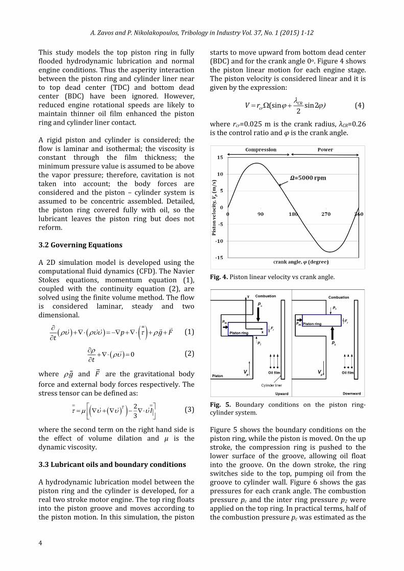
starts to move upward from bottom dead center (BDC) and for the crank angle 0o. Figure 4 shows the piston linear motion for each engine stage. The piston velocity is considered linear and it is given by the expression:
(sin sin22CR
crV r
(4)
where rcr=0.025 m is the crank radius, λCR=0.26 is the control ratio and φ is the crank angle.
Fig. 4. Piston linear velocity vs crank angle.
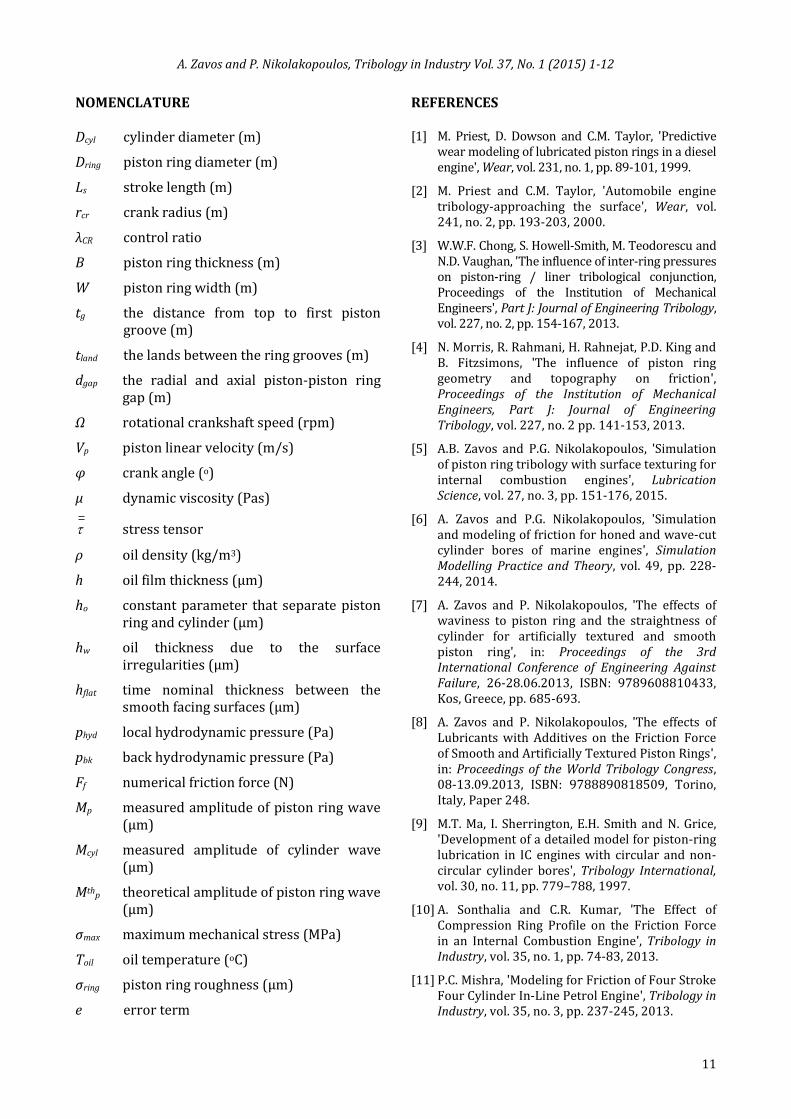
Fig. 5. Boundary conditions on the piston ring-cylinder system.
Figure 5 shows the boundary conditions on the piston ring, while the piston is moved. On the up stroke, the compression ring is pushed to the lower surface of the groove, allowing oil float into the groove. On the down stroke, the ring switches side to the top, pumping oil from the groove to cylinder wall. Figure 6 shows the gas pressures for each crank angle. The combustion pressure pc and the inter ring pressure p2 were applied on the top ring. In practical terms, half of the combustion pressure pc was estimated as the

A. Zavos and P. Nikolakopoulos, Tribology in Industry Vol. 37, No. 1 (2015) 1-12
5
inter pressure p2. Thus, the local hydrodynamic pressure phyd in the radial clearance, and the back pressure pbk due to the piston ring elasticity was developed for each crank angle. In hydrodynamic lubrication, there is no contact between the ring and liner, and the piston ring load is entirely supported by the hydrodynamic pressure in the oil film.
Fig. 6. Gas pressures versus crank angle.
The lubricant viscosity is sensitive to the temperature variations. The temperature distribution along the cylinder liner is not uniform and can be estimated using the typical conditions in two stroke motor engines. Hence, the oil temperature is assumed equal with the cylinder liner temperature. A set of simulations was performed for monograde test oils SAE 20 and SAE 30 taking the mean value of the oil temperature, oilT = 100
oC and the assumed oil density, ρ=860 kg/m3 for each crank angle position. Thereafter, the lubricant dynamic viscosity can be considered as, μ=0.00736 Pas for SAE 20 and μ=0.0097 Pas for SAE 30. 3.4 Simulation solution steps and oil
thickness The oil flow procedure in the clearance is described by the Navier Stokes equations. The radial ring motion was described by the oil thickness, as shown in Fig. 7. In practical terms, the algorithm was developed taking into account the boundary conditions on piston ring –cylinder tribo pair. The piston velocity and the
gas pressures for each crank angle were updated (Step 1). Thereafter, the nodes displacement and the distance between the piston ring liner nodes and cylinder wall (Step 2) were determined. Due to the possibility of the ring motion near to the cylinder wall, it is important to consider also a constant parameter ho, that removes the ring surface from the cylinder’s one. This parameter was obtained after the necessary grid sensitivity tests related with the friction force error. After the grid tests, it is concluded that for h0 values between 0 to 5 μm the simulation predicts a maximum friction error 20 %, while the mesh morphing failures. At the same time, when the value of ho varies from 5-10 μm the mesh morphing was achieved, and the friction error was reduced in the order to 1-8 %. In this analysis, the parameter considered as ho=7 μm while the friction error is minimum, and below of 2 %. The friction force error calculated using the next expression:
100%num valf f
fr numf
F FError
F
(5)
where numfF is the friction force coming from the
simulations and valfF corresponds to the friction
force values obtained from the published results [10,12].
Fig. 7. Simulation solution approximation.
The oil film thickness at the ring-cylinder liner was calculated taking into account the piston ring elasticity at each crankshaft position by following equation:
( , , ) ( ) ( , )o flat wh x y t h h t h x y (6)
where hflat(t) is the time nominal thickness between the smooth facing surfaces, hw (x,y) is the oil thickness due to the surface irregularities

A. Zavos and P. Nikolakopoulos, Tribology in Industry Vol. 37, No. 1 (2015) 1-12
6
and ho is a constant parameter that separate the ring’s and the cylinder’s wall. In particular, the variation of oil film for pure hydrodynamic conditions calculated for smooth facing surfaces and presented in Fig. 8.
Fig. 8. Oil film thickness versus crank angle for smooth mating surfaces.
3.5 Design quantities The pressure distribution over the piston ring is obtained, after the sequential solution of all the governing equations. In this study, the piston ring friction was obtained entirely from shear stress within the oil. Especially, the friction force is numerically calculated by the integration of stress tensor with the piston ring surface, which is interfaced with oil film, and it is defined as:
/2
/2
B
f ring
A B
F dA D dy
(7)
where Dring =0.041 m is the piston ring diameter and B is the piston ring thickness. Cast iron piston ring is considered in this work after the SEM and EDX analysis. At the same time, the mechanical stress is expressed as σ΄ and it is mentioned as the von Mises stress:
12 2 2 2
1 2 2 3 3 1
1[( ) ( ) ( ) ]
2΄ (8)
Equivalent tensile stress or von Mises stress is used to predict yielding of materials under multiaxial loading conditions using results from simple uniaxial tensile tests. This criterion is based on the determination of the distortion energy in a given material, i.e., of the energy associated with changes in the shape in that material and it is provided in order to check if
yield occurs in the top ring, especially in the worn case.
4. FLUID AND STRUCTURE ANALYSIS A 2D axisymmetric model is developed using a CFD package. Fig. 9 presents the flow chart solution of the couple field problem. Regarding the fluid field solution, tetrahedral elements are used. For this analysis, the radial clearance size between the piston ring and cylinder wall is very small. So the use of tetrahedral elements leads to 5511 number of nodes. After extensively grid sensitivity tests regarding the constant parameter ho=7μm, ten divisions were used in the radial direction and 500 divisions were used in the axial direction. Using lower number of divisions in the radial direction, the model gave a friction error between 25-20 %. At the same time, using maximum of 10 divisions this error is minimized near to 1-2 %. Thereafter, increasing the number of the divisions in the axial direction from 500 to 600, the error of the numerical prediction of the friction force was smaller than 0.5 %. The computational meshes across the lubricant film for smooth and worn profiles (see Detail B) of piston ring-cylinder are illustrated in Fig. 10. It is important to refer that the element size is in the order of 10-5 (m) near to the piston ring area. The total number of 54560 elements for smooth case and 64368 elements for worn case are used.
Fig. 9. Solution of couple field problem.

A. Zavos and P. Nikolakopoulos, Tribology in Industry Vol. 37, No. 1 (2015) 1-12
7
Fig. 10. Computational grid details of fluid structure problem.
When the convergence of pressure field calculations is confirmed, the algorithm moves the nodes of the fluid field taking into account the piston ring displacements, and the solver goes to the next fluid film solution. The fluid nodes in radial clearance between the piston ring and the cylinder liner are moved, including the Arbitrary Lagrangian Eulerian (ALE) formulation. Detailed, the displacements of the piston ring were produced after the mesh morphing. Some stages of the ALE formulation are presented by the authors in [5]. Simultaneously, simulations were performed on the computer with 8 processors (Intel core i7-3770 CPU@ 3.40 GHz) and the typical solution time varied between 50 and 120 minutes for smooth and worn case accordingly. 4.1 Convergence strategy The convergence strategy of the couple field problem achieved by two steps. First, the pressure error defined analytical by:
1
61
1
1 10
CFDn
CFDn
i Nk ki i
ipres i N
ki
i
p p
Error
p
(9)
For greater accuracy, a value of 10-6 is used for the pressure term. Second, for the structural analysis, the piston ring displacement is computed using a loop defined a critical displacement. The critical displacement depended directly on the piston ring radial contact with the cylinder. Therefore, the interaction loop was attained since the piston ring liner nodes are impossible to contact with the cylinder wall and the piston gap. Hence, the critical displacement DScr on the ring in every time step is less/equal than five percent of the
maximum displacement DSmax due to the chamber pressure, pc.
maxcrDS eDS (10)
The above assumption was computed by a typically error term e=0.05, leading to the final solution. The solution time defined for each crank angle after 4000 iterations. The number of the iterations occurred by using the above meshing requirements and the convergence tolerance to be in the order of 10-6. 5. VALIDATION RESULTS A similar flow problem in a lubricated piston ring and cylinder wall was solved, and the results for the numerical friction force were compared against the recent published results. Sonthalia’s [10] and Wakuri′s [12] results are based on the Reynolds equation and full oil lubrication conditions. In summation, the solutions have been obtained by a numerical analysis taking into account the basic geometrical dimensions of piston ring-cylinder model, and the top ring material properties. Further, the dynamic viscosity of lubricant oils are considered constant along to the cylinder liner, as the piston ring floats into the piston groove. Since, taken the above assumptions for piston ring-cylinder system, the papers of Sonthalia et. al [10] and Wakuri et. al [12] were simulated and validated, promoting thus our investigation.
Fig. 11. Numerical friction force validation with the paper of Sonthalia et. al [10].

A. Zavos and P. Nikolakopoulos, Tribology in Industry Vol. 37, No. 1 (2015) 1-12
8
In fact, a parabola top ring (type 3) simulated from Sonthalia’s study under full oil film using the relevant cylinder’s pressure, piston velocity and ring twist angle, as inputs in the simulation model. Fig. 11 shows the numerical friction results compared with the results of Sonthalia and Kumar [10]. A substantial deviation of friction was observed 10-18 % near to top dead center (TDC) and bottom dead center (BDC). Mixed lubrication at reversal points in the clearance has been ignored in this analysis and this could be a cause for the disagreement between the results of the present paper and [10]. Thus, for hydrodynamic regime near to mid-stroke the numerical friction force has a very good agreement with Sonthalia’s paper. Consequently, the validated results from Wakuri’s study have been achieved for a flat top ring lubricated with the Newtonian oil SAE 30 at
oilT =120 oC, in a four stroke diesel engine. The
variation of the gas pressure and the oil film thickness between the piston ring and cylinder is referred clearly for a rotational speed Ω=2400 rpm. Figure 12 illustrates the deviation of friction related with the paper of Wakuri’s. As presented the numerical friction has a good agreement with the published results.
Fig. 12. Numerical friction force validation with the paper of Wakuri et. al [12].
6. RESULTS AND DISCUSSIONS Results extracted concerning smooth and worn top ring profile having a constant crankshaft rotational speed Ω=5000 rpm. The effect of the Newtonian oils concerning the frictional
characteristics is examined for the same operation engine conditions. The friction force, the pressure field, the oil film and the mechanical stresses on the piston ring are obtained. SEM and EDX analysis was performed for top worn ring after 4000 operating hours. 6.1 Hydrodynamic pressure and oil film
distribution
Figure 13 shows the pressure field over the piston ring walls using a Newtonian oil SAE 20 for constant oil temperature Toil=100 oC, when the piston moves downward on expansion stage and the crank angle is φ= 90o. As expected, the piston ring floats into the piston groove in the upper level under full oil film. The hydrodynamic pressures along to the piston ring thickness were increased, when the irregularities are imposed. As the fluid intakes in the aforementioned surface modifications a hydrodynamic lift is produced which is higher than the smooth surfaces. For example, the maximum hydrodynamic pressure pmax increased substantial from 0.40 MPa to 0.71 MPa in the clearance (see Position A).
Fig. 13. Hydrodynamic pressure profile in Pa on expansion stage at mid-stroke position φ=90ο.
Fig. 14. Oil film thickness versus crank angle for smooth and worn surfaces.

A. Zavos and P. Nikolakopoulos, Tribology in Industry Vol. 37, No. 1 (2015) 1-12
9
It is evident that the local maximum hydrodynamic pressures of worn surfaces promote the oil film distribution along to the piston ring thickness. The variation of the oil film is calculated based on the equation (6) for each engine operational stage when the surface irregularities respond. As presented, in Fig. 14, the film thickness increased 10 % as the piston linear velocity increased in relation with the smooth case. 6.2 Friction force Figure 15 presents the numerical friction force at a first compression piston ring for smooth and worn surfaces lubricated with Newtonian oil SAE 20 under constant oil temperature Toil=100 oC and rotational speed Ω=5000 rpm. Mainly the maximum piston ring friction observed as the viscous shear stress increase. Hence, the friction is highly decreased in the order of 38 % when the modifications exist. This is obvious because the increment of pressures in the clearance produces larger piston ring displacements.
Fig. 15. Friction force versus crank angle for smooth and worn mating surfaces.
Regarding the level of the waviness on piston ring profile the effect of amplitude in friction results was investigated. In detail, the theoretical amplitude of the wave ring Mthp increased 10, 20 and 30 % in relation with the measured wave (Mp=9 μm) and used as a reference case (see Detail B). In this simulation, the amplitude of cylinder wave remains constant with the measured case Mcyl=7 μm. Figure 16 shows the variation of maximum friction force while the amplitude of the Mthp wave increased. For this purpose, the friction was predicted for
two types of Newtonian oils SAE 20 and SAE 30. Considering the above increment of amplitudes, the higher friction force decreased moderate 5 %. Furthermore, the used of the maximum viscosity value increases the friction force 15 %, for the same temperature oil Toil=100 oC. This phenomenon observed because the viscous shear stress is maximized.
Fig. 16. Maximum friction force versus wave amplitude of piston ring.
6.3 Wear and mechanical stresses of top ring In addition, a metallurgical analysis is performed in this work for top ring. In practical terms, scanning electron microscopy (SEM) and energy dispersive X-Ray (EDX) analysis were used. Hence, the wear and the material of first compression ring were taken after 4000 operating hours.
Fig. 17. SEM analysis of worn top ring
Figure 17 shows the worn profile of the first ring after SEM analysis. Many abrasive wear scars

A. Zavos and P. Nikolakopoulos, Tribology in Industry Vol. 37, No. 1 (2015) 1-12
10
with different lengths and widths were appeared on the surface (yellow arrows) in the sliding direction. Also, it is clear that the top ring has a peripheral chromium coating at chamfer edges (red line). In this case, EDX analysis was done given the chromium layer (spectrum 3). The results are presented in Fig. 18 where the elemental compositions of the cast iron piston ring (spectrum 2) were observed.
Fig. 18. EDX analysis of worn top ring.
Fig. 19. Mechanical stress contour of smooth and worn top ring for crank angle φ=1ο near to TDC.
The mechanical stresses are presented in Fig. 19, concerning a case of a cast iron top ring. As expected, the maximum mechanical stress is observed near to the top dead center (TDC), since the piston velocity is reduced and the oil film is thin. In this case, the increment of von Mises stress predicted in a value and not of 10.3 % for crank angle φ=1ο when the worn ring considered. As can be seen, the waviness influences strongly the structural integrity of the piston ring. 7. CONCLUSION In the present paper a numerical analysis is presented for a piston ring-cylinder model using the Navier Stokes equations. A fluid structural algorithm was solved for pure hydrodynamic conditions, considering a real data from two stroke motor engine 50 cc. The effect of surface irregularities for different Newtonian oils was examined. The friction reduction was demonstrated for worn piston rings. In practice, the surface modifications produce maximum local hydrodynamic pressures increasing the oil film in the clearance between piston ring and cylinder. Since, the friction was reduced largely, 38%, related to the smooth case. At the same time, the developed deformations of worn ring increased; hence the mechanical stresses enhanced at 10.3 %. On the other hand, by increasing the viscosity, the friction maximized at 15 % for the same engine conditions. Metrological and metallurgical analysis was done for top piston ring after 4000 operational hours. Wear scars were created in the sliding direction and a peripheral chromium layer was observed in order to conserve the shape of top ring. The simulation of the piston ring motion can be taken into account the twists and contact asperities effects, and this is a point for further research. Also, wear analysis of the top ring using multigrade oils could be addressed and compared. Acknowledgement This work was supported by Grant Ε.039 from the Research Committee of the University of Patras (Programme K. Karatheodori).
A. Zavos and P. Nikolakopoulos, Tribology in Industry Vol. 37, No. 1 (2015) 1-12
11
NOMENCLATURE Dcyl cylinder diameter (m)
Dring piston ring diameter (m)
Ls stroke length (m)
rcr crank radius (m)
λCR control ratio
B piston ring thickness (m)
W piston ring width (m)
tg the distance from top to first piston groove (m)
tland the lands between the ring grooves (m)
dgap the radial and axial piston-piston ring gap (m)
Ω rotational crankshaft speed (rpm)
Vp piston linear velocity (m/s)
φ crank angle (o)
μ dynamic viscosity (Pas)
stress tensor
ρ oil density (kg/m3)
h oil film thickness (μm)
ho constant parameter that separate piston ring and cylinder (μm)
hw oil thickness due to the surface irregularities (μm)
hflat time nominal thickness between the smooth facing surfaces (μm)
phyd local hydrodynamic pressure (Pa)
pbk back hydrodynamic pressure (Pa)
Ff numerical friction force (N)
Mp measured amplitude of piston ring wave (μm)
Mcyl measured amplitude of cylinder wave (μm)
Mthp theoretical amplitude of piston ring wave (μm)
σmax maximum mechanical stress (MPa)
Toil oil temperature (oC)
σring piston ring roughness (μm)
e error term
REFERENCES [1] M. Priest, D. Dowson and C.M. Taylor, 'Predictive
wear modeling of lubricated piston rings in a diesel engine', Wear, vol. 231, no. 1, pp. 89-101, 1999.
[2] M. Priest and C.M. Taylor, 'Automobile engine tribology-approaching the surface', Wear, vol. 241, no. 2, pp. 193-203, 2000.
[3] W.W.F. Chong, S. Howell-Smith, M. Teodorescu and N.D. Vaughan, 'The influence of inter-ring pressures on piston-ring / liner tribological conjunction, Proceedings of the Institution of Mechanical Engineers', Part J: Journal of Engineering Tribology, vol. 227, no. 2, pp. 154-167, 2013.
[4] N. Morris, R. Rahmani, H. Rahnejat, P.D. King and B. Fitzsimons, 'The influence of piston ring geometry and topography on friction', Proceedings of the Institution of Mechanical Engineers, Part J: Journal of Engineering Tribology, vol. 227, no. 2 pp. 141-153, 2013.
[5] A.B. Zavos and P.G. Nikolakopoulos, 'Simulation of piston ring tribology with surface texturing for internal combustion engines', Lubrication Science, vol. 27, no. 3, pp. 151-176, 2015.
[6] A. Zavos and P.G. Nikolakopoulos, 'Simulation and modeling of friction for honed and wave-cut cylinder bores of marine engines', Simulation Modelling Practice and Theory, vol. 49, pp. 228-244, 2014.
[7] A. Zavos and P. Nikolakopoulos, 'The effects of waviness to piston ring and the straightness of cylinder for artificially textured and smooth piston ring', in: Proceedings of the 3rd International Conference of Engineering Against Failure, 26-28.06.2013, ISBN: 9789608810433, Kos, Greece, pp. 685-693.
[8] A. Zavos and P. Nikolakopoulos, 'The effects of Lubricants with Additives on the Friction Force of Smooth and Artificially Textured Piston Rings', in: Proceedings of the World Tribology Congress, 08-13.09.2013, ISBN: 9788890818509, Torino, Italy, Paper 248.
[9] M.T. Ma, I. Sherrington, E.H. Smith and N. Grice, 'Development of a detailed model for piston-ring lubrication in IC engines with circular and non-circular cylinder bores', Tribology International, vol. 30, no. 11, pp. 779–788, 1997.
[10] A. Sonthalia and C.R. Kumar, 'The Effect of Compression Ring Profile on the Friction Force in an Internal Combustion Engine', Tribology in Industry, vol. 35, no. 1, pp. 74‐83, 2013.
[11] P.C. Mishra, 'Modeling for Friction of Four Stroke Four Cylinder In‐Line Petrol Engine', Tribology in Industry, vol. 35, no. 3, pp. 237‐245, 2013.

A. Zavos and P. Nikolakopoulos, Tribology in Industry Vol. 37, No. 1 (2015) 1-12
12
[12] Y. Wakuri, T. Hamatake, M. Soejima and T. Kitahara, 'Piston ring friction in internal combustion engines', Tribology International, vol. 25, no. 5, pp. 299‐308, 1992.
[13] T.C. Simon and H. Yong, 'Modelling of Abrasive Wear in a Piston Ring and Engine Cylinder Bore System', Tribology Transactions, vol. 47, pp. 17-22. 2004.
[14] P. Papadopoulos, M. Priest and W.M. Rainforth, 'Investigation of fundamental wear mechanisms at the piston ring and cylinder wall interface in
internal combustion engines', Proceedings of the Institution of Mechanical Engineers, Part J: Journal of Engineering Tribology, vol. 221, pp. 333-343, 2007.
[15] H. Kaleli, Y. Berthier, D. Özkan and L. Yuksek, 'Analysis of the Additive Layer Formation and Evaluation of Wear Mechanisms of Phosphorous-free and Conventional Engine Lubricants on the Surface of Cylinder Liner and Piston Rings', in: Proceedings of World Tribology Congress 2013, 08-13.09.2013, Torino, Italy.