Triathlon Knee System MIS Surgical Protocol - … Triathlon MIS Surgical... · Triathlon® Knee...
68
Triathlon ® Knee System MIS Surgical Protocol The Right Procedure with the Right Implant for Your Patient
-
Upload
hoangquynh -
Category
Documents
-
view
645 -
download
23
Transcript of Triathlon Knee System MIS Surgical Protocol - … Triathlon MIS Surgical... · Triathlon® Knee...
Triathlon®
Knee System MIS Surgical Protocol
The Right Procedure with the Right Implant for Your Patient

Triathlon Knee SystemMIS Surgical Protocol
Table of Contents
MIS Instruments . . . . . . . . . . . . . . . . . . . . . . . . . . . . . . . . . . . . . . . . . . . . . . . . . . . . . . . .2Assembly Instructions . . . . . . . . . . . . . . . . . . . . . . . . . . . . . . . . . . . . . . . . . . . . . . . . . . . .3Exposure . . . . . . . . . . . . . . . . . . . . . . . . . . . . . . . . . . . . . . . . . . . . . . . . . . . . . . . . . . . . . 18Tibial Preparation . . . . . . . . . . . . . . . . . . . . . . . . . . . . . . . . . . . . . . . . . . . . . . . . . . . . 18 Rotational Alignment . . . . . . . . . . . . . . . . . . . . . . . . . . . . . . . . . . . . . . . . . . . . . . . . . 18 Varus/Valgus Alignment . . . . . . . . . . . . . . . . . . . . . . . . . . . . . . . . . . . . . . . . . . . . . . 19 Flexion/Extension Alignment . . . . . . . . . . . . . . . . . . . . . . . . . . . . . . . . . . . . . . . . . . 19 Establishing the Tibial Resection Level . . . . . . . . . . . . . . . . . . . . . . . . . . . . . . . . . . 20 Final Tibial Resection . . . . . . . . . . . . . . . . . . . . . . . . . . . . . . . . . . . . . . . . . . . . . . . . . 21Femoral Preparation . . . . . . . . . . . . . . . . . . . . . . . . . . . . . . . . . . . . . . . . . . . . . . . . . . . 22 Femoral Intramedullary Alignment . . . . . . . . . . . . . . . . . . . . . . . . . . . . . . . . . . . . . 22 Distal Femoral Resection . . . . . . . . . . . . . . . . . . . . . . . . . . . . . . . . . . . . . . . . . . . . . . 26 Femoral A/P Sizing . . . . . . . . . . . . . . . . . . . . . . . . . . . . . . . . . . . . . . . . . . . . . . . . . . . 27 Femoral Anterior, Posterior, and Chamfer Resections . . . . . . . . . . . . . . . . . . . . . 30 PS Box Preparation . . . . . . . . . . . . . . . . . . . . . . . . . . . . . . . . . . . . . . . . . . . . . . . . . . . 33 Femoral Trial Assessment . . . . . . . . . . . . . . . . . . . . . . . . . . . . . . . . . . . . . . . . . . . . . . 36Gap Balancing and Tibial Sizing . . . . . . . . . . . . . . . . . . . . . . . . . . . . . . . . . . . . . . . . . 38 Flexion and Extension Gaps . . . . . . . . . . . . . . . . . . . . . . . . . . . . . . . . . . . . . . . . . . . . 38 Tibial Component Sizing . . . . . . . . . . . . . . . . . . . . . . . . . . . . . . . . . . . . . . . . . . . . . . 38 Tibial Trial Assessment . . . . . . . . . . . . . . . . . . . . . . . . . . . . . . . . . . . . . . . . . . . . . . . . 38 Tibial Keel Punching . . . . . . . . . . . . . . . . . . . . . . . . . . . . . . . . . . . . . . . . . . . . . . . . . . 40Patella Preparation . . . . . . . . . . . . . . . . . . . . . . . . . . . . . . . . . . . . . . . . . . . . . . . . . . . . 42 Option 1– Bone Removing Method . . . . . . . . . . . . . . . . . . . . . . . . . . . . . . . . . . . . . 42 Option 2– Bone Remaining Method . . . . . . . . . . . . . . . . . . . . . . . . . . . . . . . . . . . . . 43 Patella Trial Assessment . . . . . . . . . . . . . . . . . . . . . . . . . . . . . . . . . . . . . . . . . . . . . . . 45Component Implantation . . . . . . . . . . . . . . . . . . . . . . . . . . . . . . . . . . . . . . . . . . . . . . 46 PS or CR Femoral Component – Cemented/Cementless . . . . . . . . . . . . . . . . . . . 46 Component Implantation Primary Tibial Baseplate – Cemented/Cementless . 47 Symmetric or Asymmetric Patella . . . . . . . . . . . . . . . . . . . . . . . . . . . . . . . . . . . . . . 48 Tibial Insert . . . . . . . . . . . . . . . . . . . . . . . . . . . . . . . . . . . . . . . . . . . . . . . . . . . . . . . . . 48Closure . . . . . . . . . . . . . . . . . . . . . . . . . . . . . . . . . . . . . . . . . . . . . . . . . . . . . . . . . . . . . . . 49Catalog . . . . . . . . . . . . . . . . . . . . . . . . . . . . . . . . . . . . . . . . . . . . . . . . . . . . . . . . . . . . . . . 50Indications . . . . . . . . . . . . . . . . . . . . . . . . . . . . . . . . . . . . . . . . . . . . . . . . . . . . . . . . . . . 63
1
Stryker Orthopaedics wishes to thank the entire Triathlon MIS Surgeon Panel and the dozens of surgeons worldwide who guided the design and development of the Triathlon MIS Instrumentation .
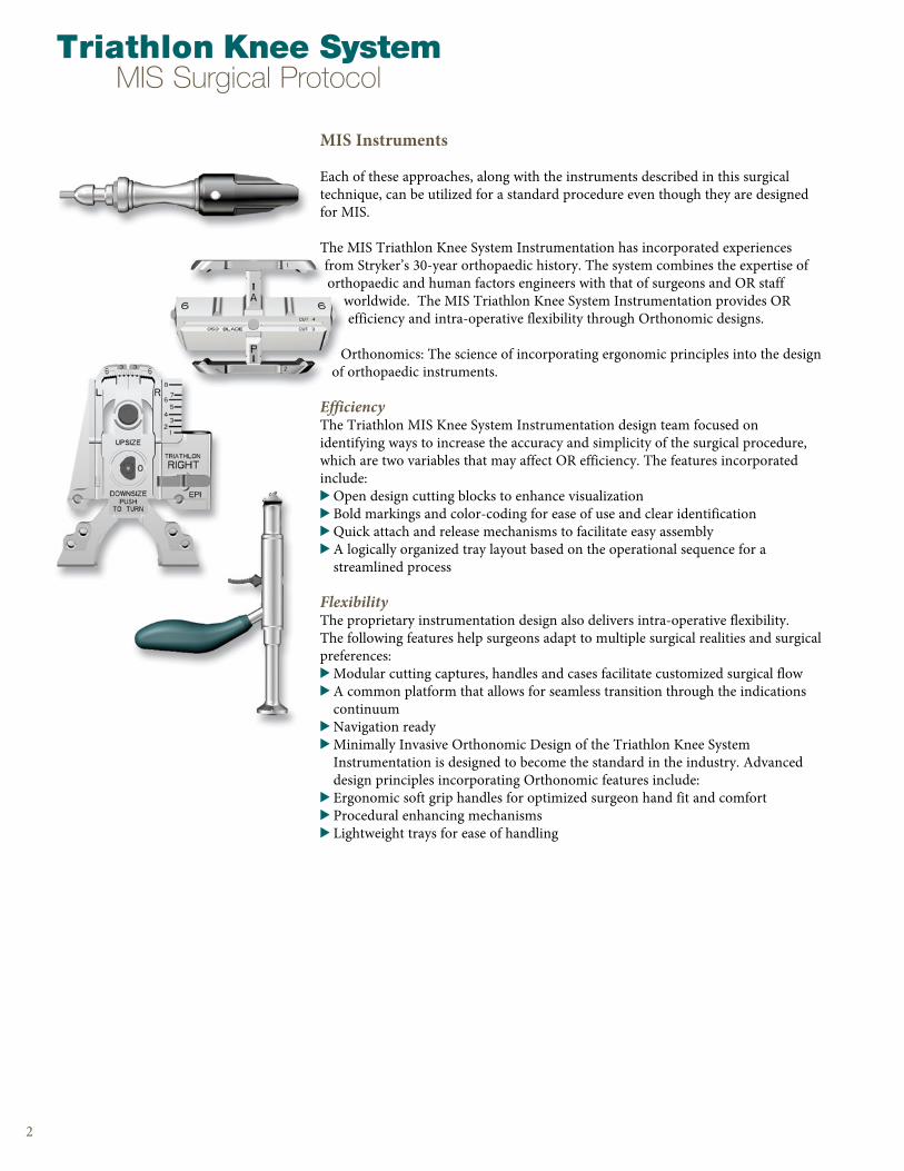
MIS Instruments
Each of these approaches, along with the instruments described in this surgical technique, can be utilized for a standard procedure even though they are designed for MIS .
The MIS Triathlon Knee System Instrumentation has incorporated experiences from Stryker’s 30-year orthopaedic history . The system combines the expertise of orthopaedic and human factors engineers with that of surgeons and OR staff
worldwide . The MIS Triathlon Knee System Instrumentation provides OR efficiency and intra-operative flexibility through Orthonomic designs .
Orthonomics: The science of incorporating ergonomic principles into the design of orthopaedic instruments .
EfficiencyThe Triathlon MIS Knee System Instrumentation design team focused on identifying ways to increase the accuracy and simplicity of the surgical procedure, which are two variables that may affect OR efficiency . The features incorporated include:> Open design cutting blocks to enhance visualization> Bold markings and color-coding for ease of use and clear identification> Quick attach and release mechanisms to facilitate easy assembly > A logically organized tray layout based on the operational sequence for a
streamlined process
FlexibilityThe proprietary instrumentation design also delivers intra-operative flexibility . The following features help surgeons adapt to multiple surgical realities and surgical preferences:> Modular cutting captures, handles and cases facilitate customized surgical flow> A common platform that allows for seamless transition through the indications
continuum> Navigation ready> Minimally Invasive Orthonomic Design of the Triathlon Knee System
Instrumentation is designed to become the standard in the industry . Advanced design principles incorporating Orthonomic features include:
> Ergonomic soft grip handles for optimized surgeon hand fit and comfort > Procedural enhancing mechanisms> Lightweight trays for ease of handling
2
Triathlon Knee SystemMIS Surgical Protocol

AssemblyInstructions
The Stryker Triathlon Knee System Instrumentation features mechanisms that provide surgeons and OR Staff a more simplified and efficient surgical experience . Assembly instructions are included in the first section of this surgical technique to assist with instruments that may be pre-assembled on the back table, as well as other instruments that need to be assembled . All of the actuating mechanisms that allow instruments to be adjusted and/or assembled have been color-coded . Those that correspond to femoral preparation are black, those for tibial preparation are bronze and those for patella preparation are gold .
Black Bronze Gold
Note: Any instrument that has been dropped should be returned to Stryker for evaluation prior to further use .

Assembly 1A
Assembly 1B
Assembly 1C
Tibial Alignment Ankle Clamp EM, Tibial Alignment Distal Assembly EM, MIS Proximal Rod EM, Tibial Stylus, MIS Tibial Resection Guide, and Tibial Adjustment Housing Assembly: > Press the bronze button 1 and advance the Distal
Assembly arm forward approximately halfway .
> Press the bronze button 2 on the Distal Assembly; put the arm into the grooves on the Ankle Clamp . Ensure that the side of the Ankle Clamp reading “proximal” is visible from above .
> Press the bronze wheel on the inferior portion of the Tibial Adjustment Housing with your thumb and insert the Proximal Rod from the superior side .
> With the bronze wheel depressed, slide the Tibial Adjustment Housing up to approximately 5cm from the arm of the Proximal Rod .
> Release the bronze wheel to engage the teeth of the Proximal Rod and lock the Adjustment Housing in place .
Note: The Tibial Adjustment Housing is available in 0 degree slope (posterior stabilized) and 3 degree slope (cruciate retaining) .
> Ensure that the bronze slide lock on the superior portion of the Distal Assembly is in the unlocked position prior to insertion of the Proximal Rod and Tibial Adjustment Housing assembly .
> Insert the Proximal Rod and Tibial Adjustment Housing assembly into the hole on the superior portion of the Distal Assembly . Note: Ensure the Proximal Rod arm extends in the same direction as the assembled Ankle Clamp .
4
Ass
em
bly
Inst
ructi
ons
Triathlon Knee SystemMIS Surgical Protocol
5
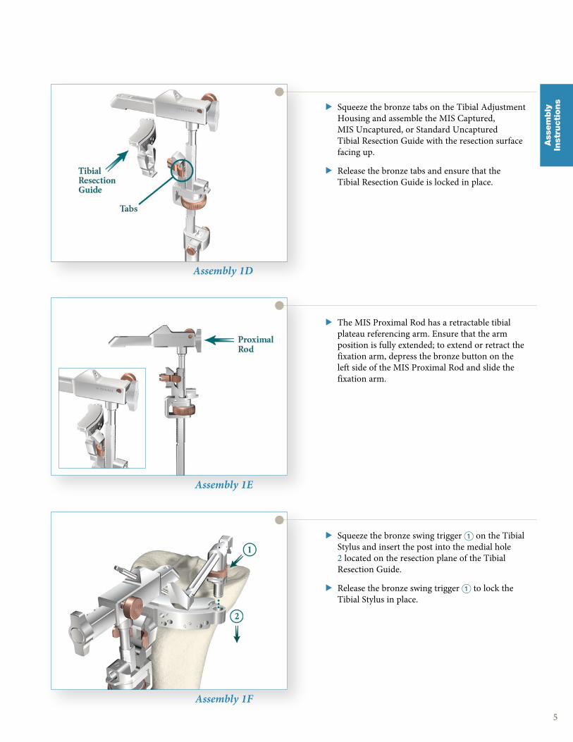
Assembly 1D
Assembly 1E
Assembly 1F
> Squeeze the bronze tabs on the Tibial Adjustment Housing and assemble the MIS Captured, MIS Uncaptured, or Standard Uncaptured Tibial Resection Guide with the resection surface facing up .
> Release the bronze tabs and ensure that the Tibial Resection Guide is locked in place .
> Squeeze the bronze swing trigger 1 on the Tibial Stylus and insert the post into the medial hole 2 located on the resection plane of the Tibial Resection Guide .
> Release the bronze swing trigger 1 to lock the Tibial Stylus in place .
> The MIS Proximal Rod has a retractable tibial plateau referencing arm . Ensure that the arm position is fully extended; to extend or retract the fixation arm, depress the bronze button on the left side of the MIS Proximal Rod and slide the fixation arm .
Ass
em
bly
Inst
ructi
ons
6
Assembly 2A
Assembly 2B
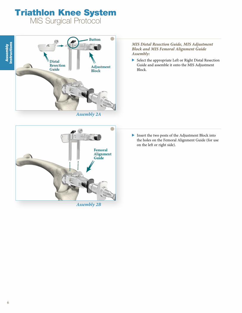
MIS Distal Resection Guide, MIS Adjustment Block and MIS Femoral Alignment Guide Assembly:> Select the appropriate Left or Right Distal Resection
Guide and assemble it onto the MIS Adjustment Block .
> Insert the two posts of the Adjustment Block into the holes on the Femoral Alignment Guide (for use on the left or right side) .
Triathlon Knee SystemMIS Surgical Protocol
Ass
em
bly
Inst
ructi
ons
7
Ass
em
bly
Inst
ructi
ons
Assembly 3A
Assembly 3B
Assembly 3C
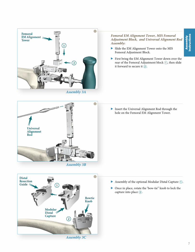
Femoral EM Alignment Tower, MIS Femoral Adjustment Block, and Universal Alignment Rod Assembly:> Slide the EM Alignment Tower onto the MIS
Femoral Adjustment Block .
> First bring the EM Alignment Tower down over the rear of the Femoral Adjustment block 1, then slide it forward to secure it 2 .
> Insert the Universal Alignment Rod through the hole on the Femoral EM Alignment Tower .
> Assembly of the optional Modular Distal Capture 1 .
> Once in place, rotate the ‘bow-tie” knob to lock the capture into place 2 .

Assembly 4A
Assembly 4B
Assembly 4C
MIS Femoral A/P Sizer and MIS Femoral Stylus Assembly:> Assemble the Left/Right modular body onto the
MIS Femoral A/P Sizer Adjustment Housing by first unlocking the assembly latch, sliding the Left or Right body onto the Adjustment Housing, then turning the latch to the lock position .
> Final Assembly .
> Slide the MIS Femoral Stylus into the medial hole of the MIS Femoral A/P Sizer .
> For A/P translation, insert the male hex of the MIS Femoral Flexion Impactor into the black hex interface of the A/P Sizer Adjustment Housing . Press and rotate to adjust A/P translation up or down by up to 1 .5mm .
8
Triathlon Knee SystemMIS Surgical Protocol
Ass
em
bly
Inst
ructi
ons
9
Ass
em
bly
Inst
ructi
ons
Assembly 5A
Assembly 5B
Assembly 5C
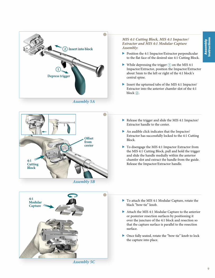
MIS 4:1 Cutting Block, MIS 4:1 Impactor/Extractor and MIS 4:1 Modular Capture Assembly:> Position the 4:1 Impactor/Extractor perpendicular
to the flat face of the desired size 4:1 Cutting Block .
> While depressing the trigger 1 on the MIS 4:1 Impactor/Extractor, position the Impactor/Extractor about 5mm to the left or right of the 4:1 block’s central spine .
> Insert the upturned tabs of the MIS 4:1 Impactor/Extractor into the anterior chamfer slot of the 4:1 block 2 .
> Release the trigger and slide the MIS 4:1 Impactor/Extractor handle to the center .
> An audible click indicates that the Impactor/Extractor has successfully locked to the 4:1 Cutting Block .
> To disengage the MIS 4:1 Impactor Extractor from the MIS 4:1 Cutting Block, pull and hold the trigger and slide the handle medially within the anterior chamfer slot and extract the handle from the guide . Release the Impactor/Extractor handle .
> To attach the MIS 4:1 Modular Capture, rotate the black “bow-tie” knob .
> Attach the MIS 4:1 Modular Capture to the anterior or posterior resection surfaces by positioning it over the juncture of the 4:1 block and resection so that the capture surface is parallel to the resection surface .
> Once fully seated, rotate the “bow-tie” knob to lock the capture into place .
Assembly 6A
Assembly 6B
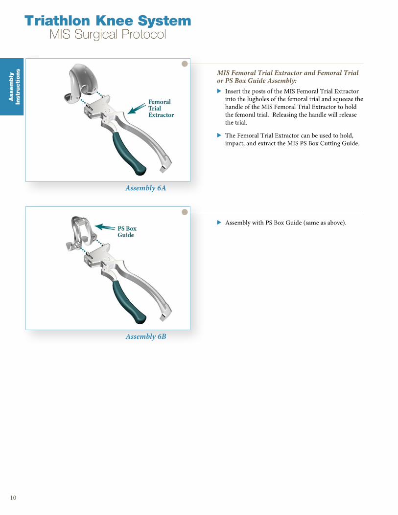
MIS Femoral Trial Extractor and Femoral Trial or PS Box Guide Assembly:> Insert the posts of the MIS Femoral Trial Extractor
into the lugholes of the femoral trial and squeeze the handle of the MIS Femoral Trial Extractor to hold the femoral trial . Releasing the handle will release the trial .
> The Femoral Trial Extractor can be used to hold, impact, and extract the MIS PS Box Cutting Guide .
> Assembly with PS Box Guide (same as above) .
10
Triathlon Knee SystemMIS Surgical Protocol
Ass
em
bly
Inst
ructi
ons
11
Ass
em
bly
Inst
ructi
ons
Assembly 7A
Assembly 7B
Assembly 8
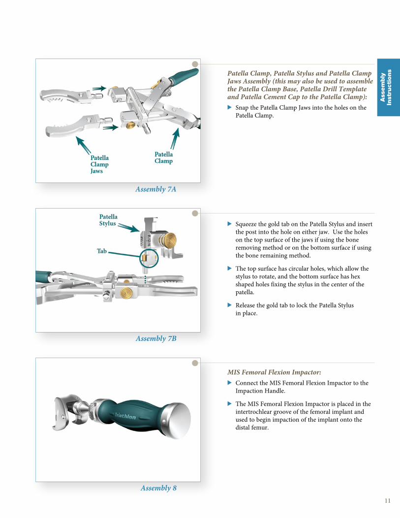
Patella Clamp, Patella Stylus and Patella Clamp Jaws Assembly (this may also be used to assemble the Patella Clamp Base, Patella Drill Template and Patella Cement Cap to the Patella Clamp):> Snap the Patella Clamp Jaws into the holes on the
Patella Clamp .
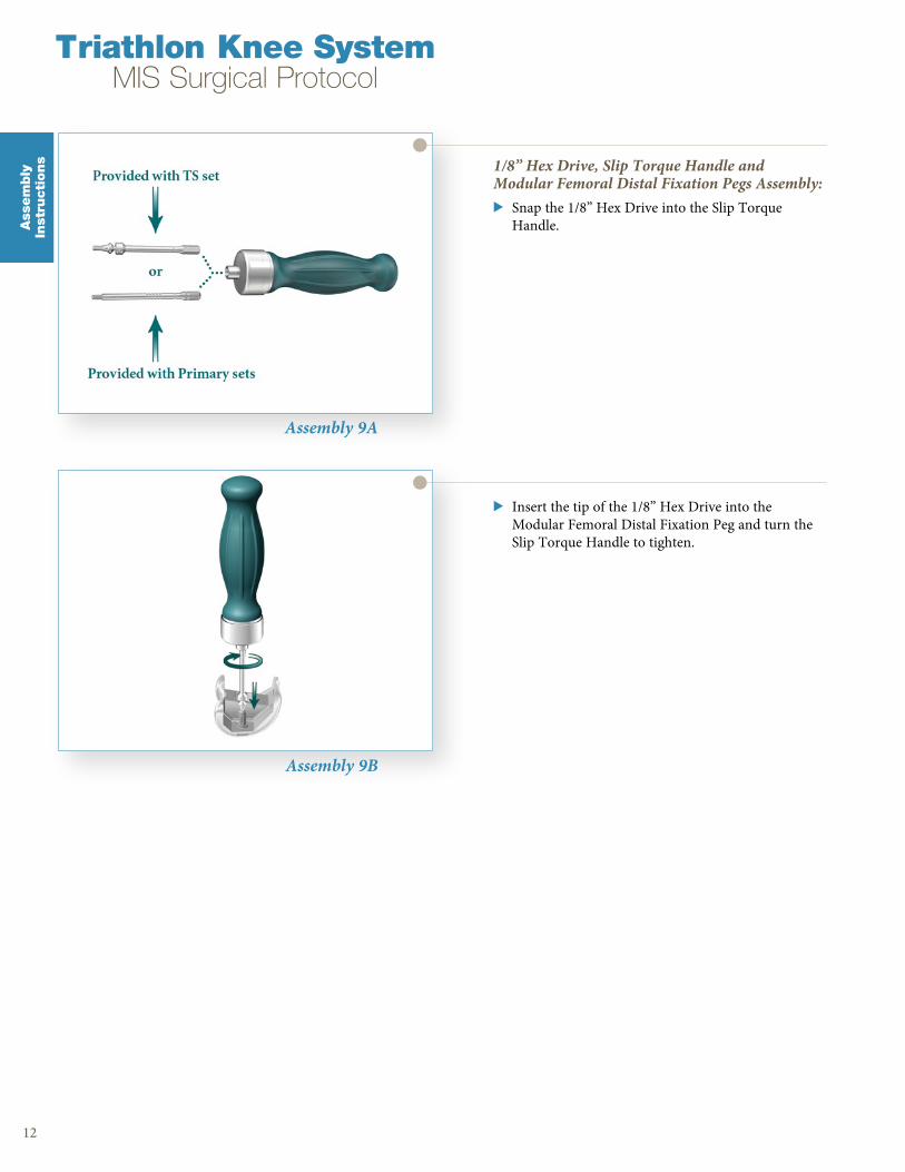
> Squeeze the gold tab on the Patella Stylus and insert the post into the hole on either jaw . Use the holes on the top surface of the jaws if using the bone removing method or on the bottom surface if using the bone remaining method .
> The top surface has circular holes, which allow the stylus to rotate, and the bottom surface has hex shaped holes fixing the stylus in the center of the patella .
> Release the gold tab to lock the Patella Stylus in place .
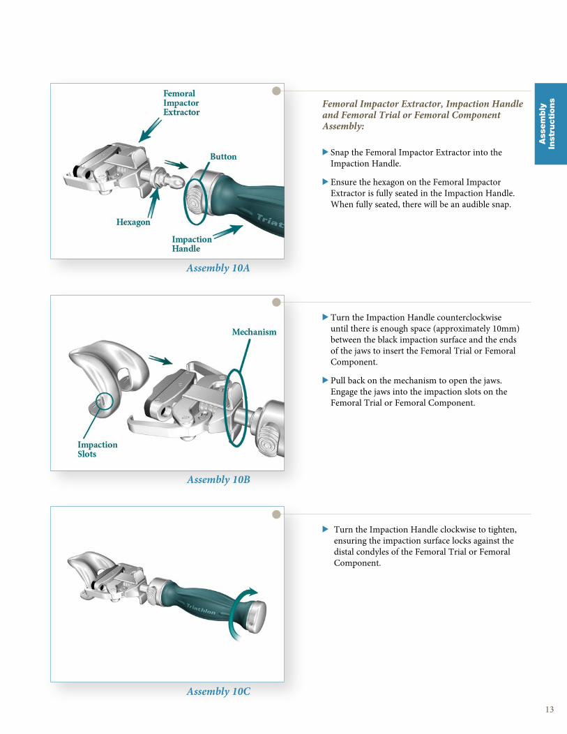
MIS Femoral Flexion Impactor:> Connect the MIS Femoral Flexion Impactor to the
Impaction Handle .
> The MIS Femoral Flexion Impactor is placed in the intertrochlear groove of the femoral implant and used to begin impaction of the implant onto the distal femur .
12
Assembly 9A
Assembly 9B
1/8” Hex Drive, Slip Torque Handle and Modular Femoral Distal Fixation Pegs Assembly:> Snap the 1/8” Hex Drive into the Slip Torque
Handle .
> Insert the tip of the 1/8” Hex Drive into the Modular Femoral Distal Fixation Peg and turn the Slip Torque Handle to tighten .
Triathlon Knee SystemMIS Surgical Protocol
Ass
em
bly
Inst
ructi
ons
13
Ass
em
bly
Inst
ructi
ons
Assembly 10A
Assembly 10B
Assembly 10C
Femoral Impactor Extractor, Impaction Handle and Femoral Trial or Femoral Component Assembly:
> Snap the Femoral Impactor Extractor into the Impaction Handle .
> Ensure the hexagon on the Femoral Impactor Extractor is fully seated in the Impaction Handle . When fully seated, there will be an audible snap .
> Turn the Impaction Handle counterclockwise until there is enough space (approximately 10mm) between the black impaction surface and the ends of the jaws to insert the Femoral Trial or Femoral Component .
> Pull back on the mechanism to open the jaws . Engage the jaws into the impaction slots on the Femoral Trial or Femoral Component .
> Turn the Impaction Handle clockwise to tighten, ensuring the impaction surface locks against the distal condyles of the Femoral Trial or Femoral Component .
Assembly 11A
Assembly 11B
Assembly 11C
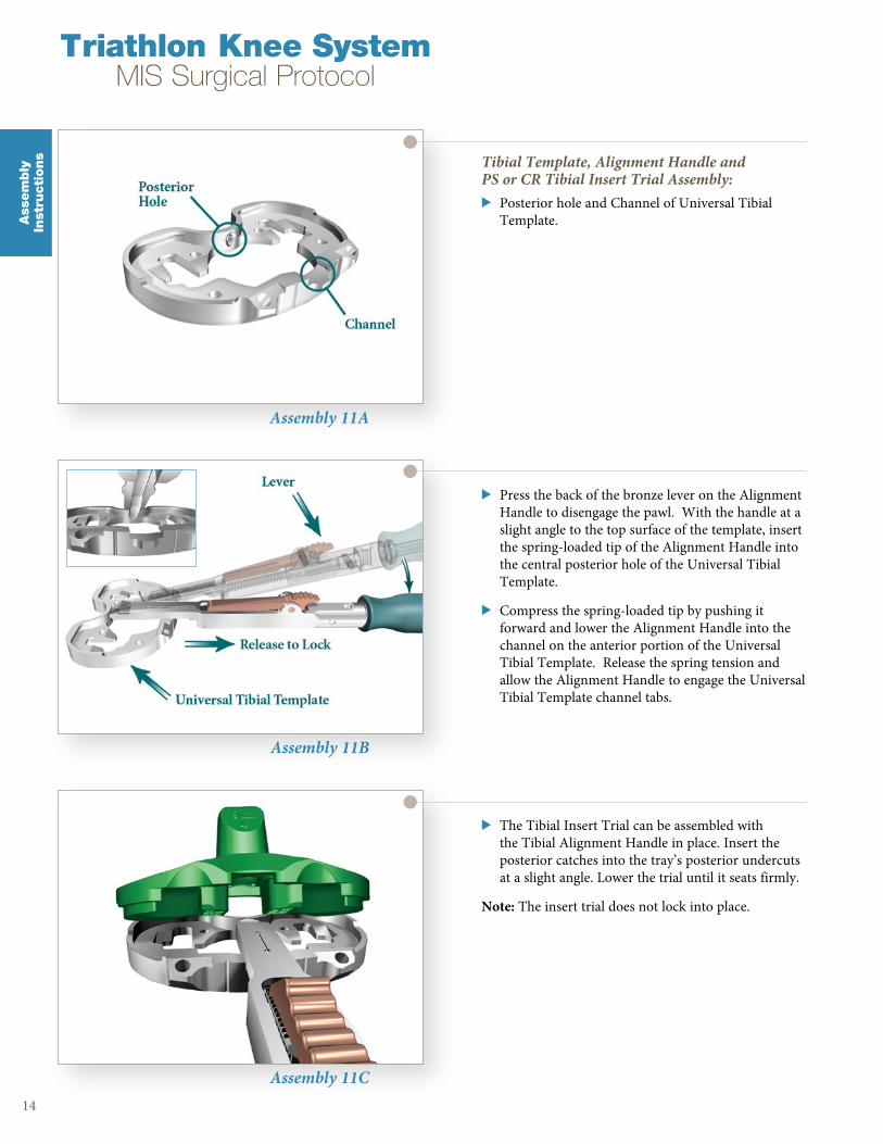
Tibial Template, Alignment Handle and PS or CR Tibial Insert Trial Assembly:> Posterior hole and Channel of Universal Tibial
Template .
> Press the back of the bronze lever on the Alignment Handle to disengage the pawl . With the handle at a slight angle to the top surface of the template, insert the spring-loaded tip of the Alignment Handle into the central posterior hole of the Universal Tibial Template .
> Compress the spring-loaded tip by pushing it forward and lower the Alignment Handle into the channel on the anterior portion of the Universal Tibial Template . Release the spring tension and allow the Alignment Handle to engage the Universal Tibial Template channel tabs .
> The Tibial Insert Trial can be assembled with the Tibial Alignment Handle in place . Insert the posterior catches into the tray’s posterior undercuts at a slight angle . Lower the trial until it seats firmly .
Note: The insert trial does not lock into place .
14
Ass
em
bly
Inst
ructi
ons
Triathlon Knee SystemMIS Surgical Protocol
15
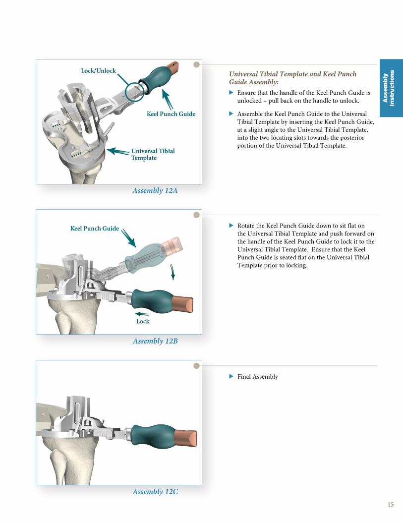
Assembly 12A
Assembly 12B
Assembly 12C
> Rotate the Keel Punch Guide down to sit flat on the Universal Tibial Template and push forward on the handle of the Keel Punch Guide to lock it to the Universal Tibial Template . Ensure that the Keel Punch Guide is seated flat on the Universal Tibial Template prior to locking .
Universal Tibial Template and Keel Punch Guide Assembly:> Ensure that the handle of the Keel Punch Guide is
unlocked – pull back on the handle to unlock .
> Assemble the Keel Punch Guide to the Universal Tibial Template by inserting the Keel Punch Guide, at a slight angle to the Universal Tibial Template, into the two locating slots towards the posterior portion of the Universal Tibial Template .
> Final AssemblyA
ssem
bly
Inst
ructi
ons
16
Triathlon Knee SystemMIS Surgical Protocol

SurgicalProcedure
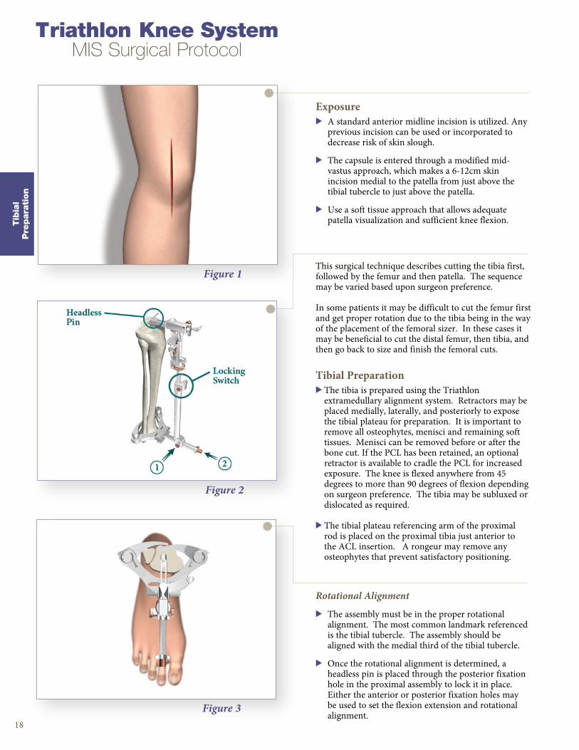
Figure 1
Exposure> A standard anterior midline incision is utilized . Any
previous incision can be used or incorporated to decrease risk of skin slough .
> The capsule is entered through a modified mid-vastus approach, which makes a 6-12cm skin incision medial to the patella from just above the tibial tubercle to just above the patella .
> Use a soft tissue approach that allows adequate patella visualization and sufficient knee flexion .
18
Triathlon Knee SystemMIS Surgical Protocol
Tib
ial
Pre
para
tion
Figure 3
This surgical technique describes cutting the tibia first, followed by the femur and then patella . The sequence may be varied based upon surgeon preference .
In some patients it may be difficult to cut the femur first and get proper rotation due to the tibia being in the way of the placement of the femoral sizer . In these cases it may be beneficial to cut the distal femur, then tibia, and then go back to size and finish the femoral cuts .
Tibial Preparation> The tibia is prepared using the Triathlon
extramedullary alignment system . Retractors may be placed medially, laterally, and posteriorly to expose the tibial plateau for preparation . It is important to remove all osteophytes, menisci and remaining soft tissues . Menisci can be removed before or after the bone cut . If the PCL has been retained, an optional retractor is available to cradle the PCL for increased exposure . The knee is flexed anywhere from 45 degrees to more than 90 degrees of flexion depending on surgeon preference . The tibia may be subluxed or dislocated as required .
> The tibial plateau referencing arm of the proximal rod is placed on the proximal tibia just anterior to the ACL insertion . A rongeur may remove any osteophytes that prevent satisfactory positioning .
Rotational Alignment
> The assembly must be in the proper rotational alignment . The most common landmark referenced is the tibial tubercle . The assembly should be aligned with the medial third of the tibial tubercle .
> Once the rotational alignment is determined, a headless pin is placed through the posterior fixation hole in the proximal assembly to lock it in place . Either the anterior or posterior fixation holes may be used to set the flexion extension and rotational alignment .
Figure 2
Instrument Bar
19
Tib
ial
Pre
para
tion
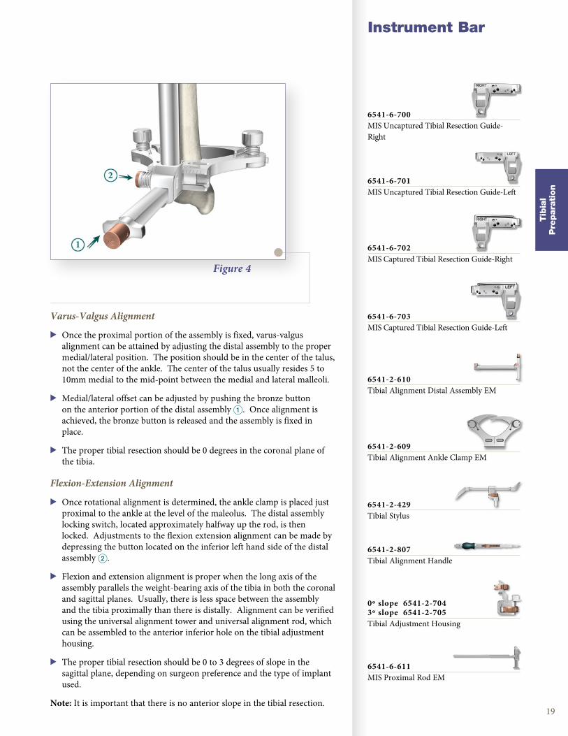
Varus-Valgus Alignment
> Once the proximal portion of the assembly is fixed, varus-valgus alignment can be attained by adjusting the distal assembly to the proper medial/lateral position . The position should be in the center of the talus, not the center of the ankle . The center of the talus usually resides 5 to 10mm medial to the mid-point between the medial and lateral malleoli .
> Medial/lateral offset can be adjusted by pushing the bronze button on the anterior portion of the distal assembly 1 . Once alignment is achieved, the bronze button is released and the assembly is fixed in place .
> The proper tibial resection should be 0 degrees in the coronal plane of the tibia .
Figure 4
Flexion-Extension Alignment
> Once rotational alignment is determined, the ankle clamp is placed just proximal to the ankle at the level of the maleolus . The distal assembly locking switch, located approximately halfway up the rod, is then locked . Adjustments to the flexion extension alignment can be made by depressing the button located on the inferior left hand side of the distal assembly 2 .
> Flexion and extension alignment is proper when the long axis of the assembly parallels the weight-bearing axis of the tibia in both the coronal and sagittal planes . Usually, there is less space between the assembly and the tibia proximally than there is distally . Alignment can be verified using the universal alignment tower and universal alignment rod, which can be assembled to the anterior inferior hole on the tibial adjustment housing .
> The proper tibial resection should be 0 to 3 degrees of slope in the sagittal plane, depending on surgeon preference and the type of implant used .
Note: It is important that there is no anterior slope in the tibial resection .
6541-6-700MIS Uncaptured Tibial Resection Guide-Right
6541-6-701MIS Uncaptured Tibial Resection Guide-Left
6541-6-702MIS Captured Tibial Resection Guide-Right
6541-6-703MIS Captured Tibial Resection Guide-Left
6541-2-609Tibial Alignment Ankle Clamp EM
6541-2-610Tibial Alignment Distal Assembly EM
0º slope 6541-2-7043º slope 6541-2-705Tibial Adjustment Housing
6541-2-429Tibial Stylus
6541-6-611MIS Proximal Rod EM
6541-2-807Tibial Alignment Handle
20
Triathlon Knee SystemMIS Surgical Protocol
Tib
ial
Pre
para
tion
Figure 5
Figure 6
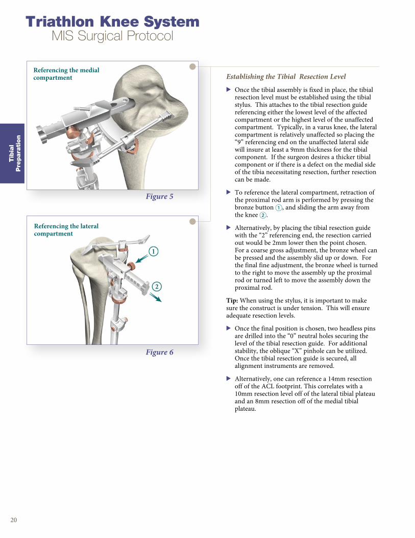
Establishing the Tibial Resection Level
> Once the tibial assembly is fixed in place, the tibial resection level must be established using the tibial stylus . This attaches to the tibial resection guide referencing either the lowest level of the affected compartment or the highest level of the unaffected compartment . Typically, in a varus knee, the lateral compartment is relatively unaffected so placing the “9” referencing end on the unaffected lateral side will insure at least a 9mm thickness for the tibial component . If the surgeon desires a thicker tibial component or if there is a defect on the medial side of the tibia necessitating resection, further resection can be made .
> To reference the lateral compartment, retraction of the proximal rod arm is performed by pressing the bronze button 1, and sliding the arm away from the knee 2 .
> Alternatively, by placing the tibial resection guide with the “2” referencing end, the resection carried out would be 2mm lower then the point chosen . For a coarse gross adjustment, the bronze wheel can be pressed and the assembly slid up or down . For the final fine adjustment, the bronze wheel is turned to the right to move the assembly up the proximal rod or turned left to move the assembly down the proximal rod .
Tip: When using the stylus, it is important to make sure the construct is under tension . This will ensure adequate resection levels .
> Once the final position is chosen, two headless pins are drilled into the “0” neutral holes securing the level of the tibial resection guide . For additional stability, the oblique “X” pinhole can be utilized . Once the tibial resection guide is secured, all alignment instruments are removed .
> Alternatively, one can reference a 14mm resection off of the ACL footprint . This correlates with a 10mm resection level off of the lateral tibial plateau and an 8mm resection off of the medial tibial plateau .
Referencing the medial compartment
Referencing the lateral compartment

Figure 7
Instrument Bar
21
Final Tibial Resection
> Once all alignment instruments are removed leaving the tibial resection guide in place, the proximal tibia is osteotomized using either the right or left captured or uncaptured tibial resection guide . If the entire resection cannot be completed, the guide is removed and the resection completed free-hand . Care must always be taken not to injure the patella tendon, neurovascular structures, or collateral ligaments . Often some bone is left unresected near the posterior aspect of the lateral tibial plateau and the anterior aspect of the lateral tibial plateau near Gerdy’s tubercle . Once the resection guide is removed, final resection can be completed either with an oscillating saw, bone file or a rongeur .
Note: Leaving the pins in place will allow for an additional 2mm or 4mm of tibial resection . The pins must be removed prior to cutting the tibial keel .
Tib
ial
Pre
para
tion
6541-2-807Tibial Alignment Handle
6541-6-700MIS Uncaptured Tibial Resection Guide-Right
6541-6-701MIS Uncaptured Tibial Resection Guide-Left
6541-6-702MIS Captured Tibial Resection Guide-Right
6541-6-703MIS Captured Tibial Resection Guide-Left
6541-4-003Headless Pins - 3”
6541-2-609Tibial Alignment Ankle Clamp EM
6541-2-610Tibial Alignment Distal Assembly EM
0º slope 6541-2-7043º slope 6541-2-705Tibial Adjustment Housing
6541-2-429Tibial Stylus
6541-6-611MIS Proximal Rod EM
Triathlon Knee SystemMIS Surgical Protocol
Figure 8
Figure 9
Figure 10
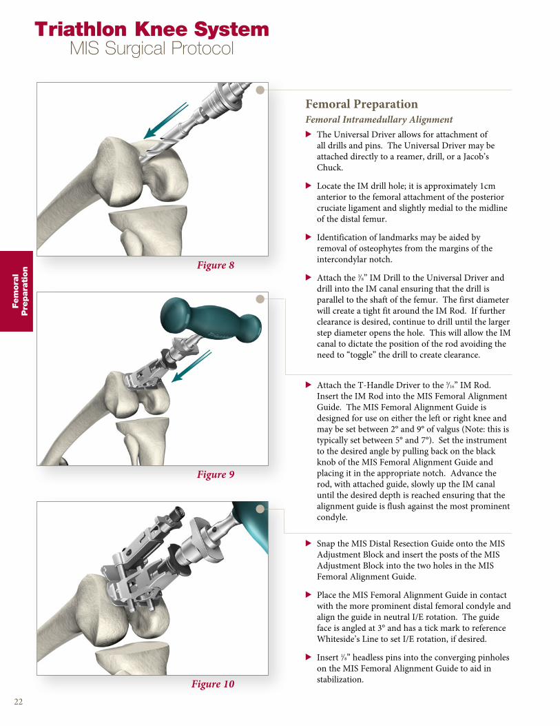
Femoral PreparationFemoral Intramedullary Alignment> The Universal Driver allows for attachment of
all drills and pins . The Universal Driver may be attached directly to a reamer, drill, or a Jacob’s Chuck .
> Locate the IM drill hole; it is approximately 1cm anterior to the femoral attachment of the posterior cruciate ligament and slightly medial to the midline of the distal femur .
> Identification of landmarks may be aided by removal of osteophytes from the margins of the intercondylar notch .
> Attach the 3/8” IM Drill to the Universal Driver and drill into the IM canal ensuring that the drill is parallel to the shaft of the femur . The first diameter will create a tight fit around the IM Rod . If further clearance is desired, continue to drill until the larger step diameter opens the hole . This will allow the IM canal to dictate the position of the rod avoiding the need to “toggle” the drill to create clearance .
22
> Attach the T-Handle Driver to the 5/16” IM Rod . Insert the IM Rod into the MIS Femoral Alignment Guide . The MIS Femoral Alignment Guide is designed for use on either the left or right knee and may be set between 2° and 9° of valgus (Note: this is typically set between 5° and 7°) . Set the instrument to the desired angle by pulling back on the black knob of the MIS Femoral Alignment Guide and placing it in the appropriate notch . Advance the rod, with attached guide, slowly up the IM canal until the desired depth is reached ensuring that the alignment guide is flush against the most prominent condyle .
> Snap the MIS Distal Resection Guide onto the MIS Adjustment Block and insert the posts of the MIS Adjustment Block into the two holes in the MIS Femoral Alignment Guide .
> Place the MIS Femoral Alignment Guide in contact with the more prominent distal femoral condyle and align the guide in neutral I/E rotation . The guide face is angled at 3° and has a tick mark to reference Whiteside’s Line to set I/E rotation, if desired .
> Insert 1/8” headless pins into the converging pinholes on the MIS Femoral Alignment Guide to aid in stabilization .
Fem
ora
lP
repara
tion

Figure 11
Instrument Bar
23
> Position the leg in 45°-60° of flexion .
> The MIS Adjustment Block allows for a 2mm through 12mm resection level .
> Press the black button on the end of the MIS Adjustment Block and push/pull the carrier to set the resection to the desired level .
Figure 12
> The Triathlon MIS Knee System Instruments allow for a clear view of the bone that is being resected to ensure the appropriate level is set .
> Slide the Adjustment Block Assembly posteriorly within the Femoral Alignment Guide until the Distal Resection Guide contacts the anterior surface of the femur .
Fem
ora
lP
repara
tion
6541-4-801Universal Driver
6541-4-5383/8” IM Drill
6541-4-800T-Handle Driver
6541-4-5165/16” IM Rod
6541-5-601MIS Femoral Adjustment Block
6541-5-629MIS Femoral Alignment Guide
6541-5-721MIS Distal Resection Guide - Left
6541-5-722MIS Distal Resection Guide - Right
6541-4-003Headless Pins - 3”
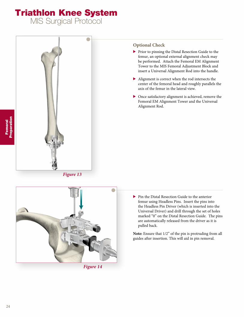
Figure 14
Optional Check> Prior to pinning the Distal Resection Guide to the
femur, an optional external alignment check may be performed . Attach the Femoral EM Alignment Tower to the MIS Femoral Adjustment Block and insert a Universal Alignment Rod into the handle .
> Alignment is correct when the rod intersects the center of the femoral head and roughly parallels the axis of the femur in the lateral view .
> Once satisfactory alignment is achieved, remove the Femoral EM Alignment Tower and the Universal Alignment Rod .
24
> Pin the Distal Resection Guide to the anterior femur using Headless Pins . Insert the pins into the Headless Pin Driver (which is inserted into the Universal Driver) and drill through the set of holes marked “0” on the Distal Resection Guide . The pins are automatically released from the driver as it is pulled back .
Note: Ensure that 1/2” of the pin is protruding from all guides after insertion . This will aid in pin removal .
Figure 13
Triathlon Knee SystemMIS Surgical Protocol
Fem
ora
lP
repara
tion
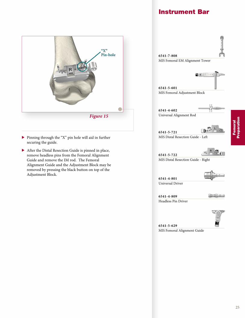
Figure 15
Instrument Bar
25
> Pinning through the “X” pin hole will aid in further securing the guide .
> After the Distal Resection Guide is pinned in place, remove headless pins from the Femoral Alignment Guide and remove the IM rod . The Femoral Alignment Guide and the Adjustment Block may be removed by pressing the black button on top of the Adjustment Block .
Fem
ora
lP
repara
tion
6541-5-601MIS Femoral Adjustment Block
6541-7-808MIS Femoral EM Alignment Tower
6541-4-801Universal Driver
6541-4-602Universal Alignment Rod
6541-4-809Headless Pin Driver
6541-5-721MIS Distal Resection Guide - Left
6541-5-722MIS Distal Resection Guide - Right
6541-5-629MIS Femoral Alignment Guide
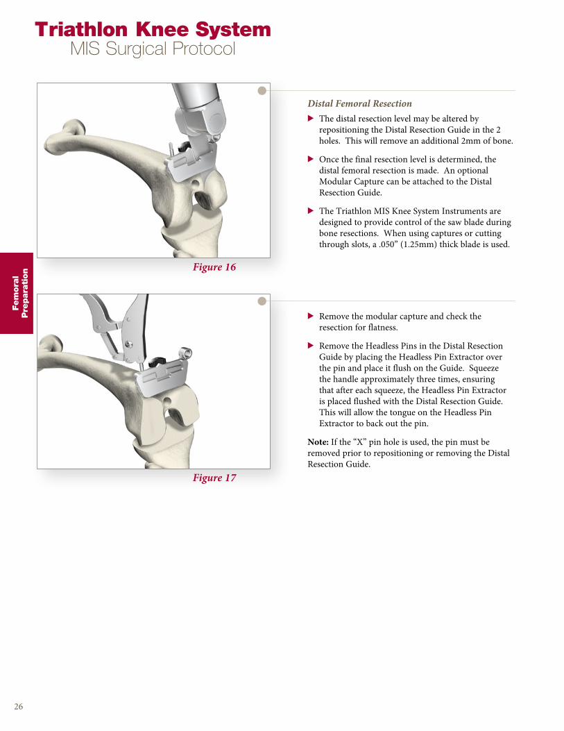
Figure 16
Figure 17
Distal Femoral Resection> The distal resection level may be altered by
repositioning the Distal Resection Guide in the 2 holes . This will remove an additional 2mm of bone .
> Once the final resection level is determined, the distal femoral resection is made . An optional Modular Capture can be attached to the Distal Resection Guide .
> The Triathlon MIS Knee System Instruments are designed to provide control of the saw blade during bone resections . When using captures or cutting through slots, a .050” (1 .25mm) thick blade is used .
26
> Remove the modular capture and check the resection for flatness .
> Remove the Headless Pins in the Distal Resection Guide by placing the Headless Pin Extractor over the pin and place it flush on the Guide . Squeeze the handle approximately three times, ensuring that after each squeeze, the Headless Pin Extractor is placed flushed with the Distal Resection Guide . This will allow the tongue on the Headless Pin Extractor to back out the pin .
Note: If the “X” pin hole is used, the pin must be removed prior to repositioning or removing the Distal Resection Guide .
Triathlon Knee SystemMIS Surgical Protocol
Fem
ora
lP
repara
tion
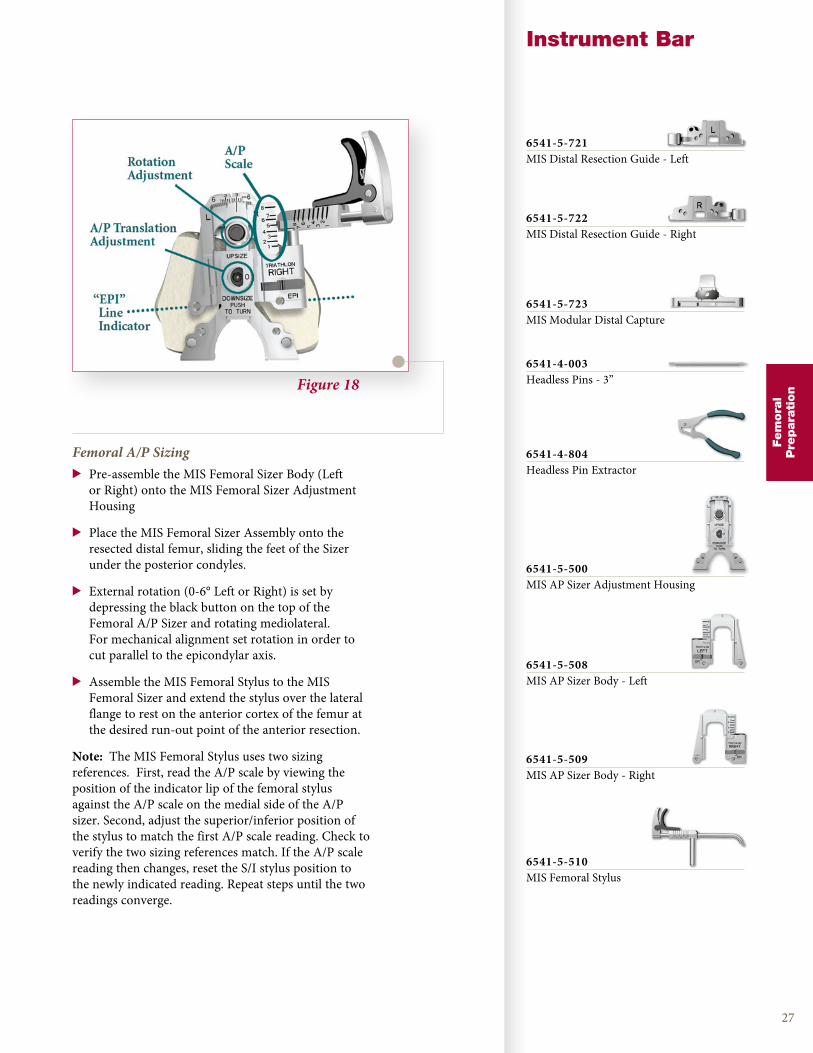
Figure 18
Instrument Bar
27
Femoral A/P Sizing> Pre-assemble the MIS Femoral Sizer Body (Left
or Right) onto the MIS Femoral Sizer Adjustment Housing
> Place the MIS Femoral Sizer Assembly onto the resected distal femur, sliding the feet of the Sizer under the posterior condyles .
> External rotation (0-6° Left or Right) is set by depressing the black button on the top of the Femoral A/P Sizer and rotating mediolateral . For mechanical alignment set rotation in order to cut parallel to the epicondylar axis .
> Assemble the MIS Femoral Stylus to the MIS Femoral Sizer and extend the stylus over the lateral flange to rest on the anterior cortex of the femur at the desired run-out point of the anterior resection .
Note: The MIS Femoral Stylus uses two sizing references . First, read the A/P scale by viewing the position of the indicator lip of the femoral stylus against the A/P scale on the medial side of the A/P sizer . Second, adjust the superior/inferior position of the stylus to match the first A/P scale reading . Check to verify the two sizing references match . If the A/P scale reading then changes, reset the S/I stylus position to the newly indicated reading . Repeat steps until the two readings converge .
Fem
ora
lP
repara
tion
6541-5-721MIS Distal Resection Guide - Left
6541-5-722MIS Distal Resection Guide - Right
6541-5-723MIS Modular Distal Capture
6541-4-003Headless Pins - 3”
6541-4-804Headless Pin Extractor
6541-5-500MIS AP Sizer Adjustment Housing
6541-5-508MIS AP Sizer Body - Left
6541-5-509MIS AP Sizer Body - Right
6541-5-510MIS Femoral Stylus
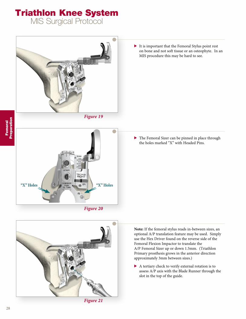
Figure 19
Figure 20
Figure 21
> It is important that the Femoral Stylus point rest on bone and not soft tissue or an osteophyte . In an MIS procedure this may be hard to see .
28
> The Femoral Sizer can be pinned in place through the holes marked “X” with Headed Pins .
Note: If the femoral stylus reads in-between sizes, an optional A/P translation feature may be used . Simply use the Hex Driver found on the reverse side of the Femoral Flexion Impactor to translate the A/P Femoral Sizer up or down 1 .5mm . (Triathlon Primary prosthesis grows in the anterior direction approximately 3mm between sizes .)
> A tertiary check to verify external rotation is to assess A/P axis with the Blade Runner through the slot in the top of the guide .
Triathlon Knee SystemMIS Surgical Protocol
Fem
ora
lP
repara
tion
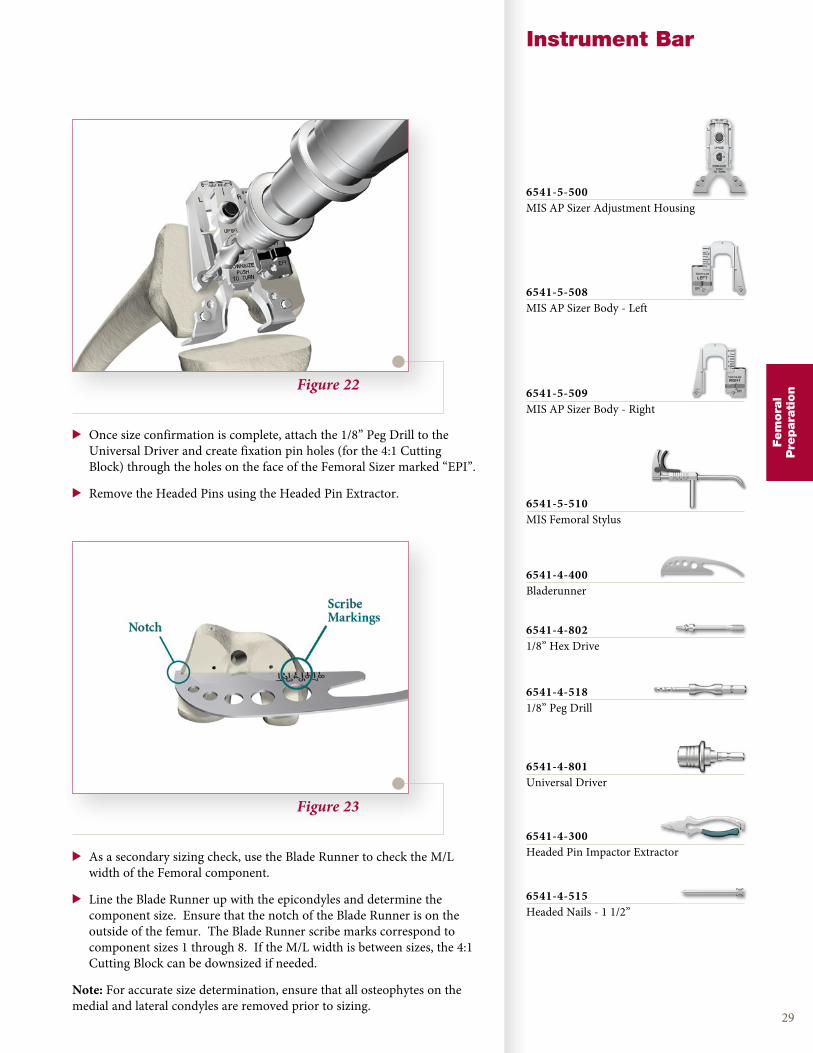
Figure 22
Instrument Bar
29
> Once size confirmation is complete, attach the 1/8” Peg Drill to the Universal Driver and create fixation pin holes (for the 4:1 Cutting Block) through the holes on the face of the Femoral Sizer marked “EPI” .
> Remove the Headed Pins using the Headed Pin Extractor .
Figure 23
> As a secondary sizing check, use the Blade Runner to check the M/L width of the Femoral component .
> Line the Blade Runner up with the epicondyles and determine the component size . Ensure that the notch of the Blade Runner is on the outside of the femur . The Blade Runner scribe marks correspond to component sizes 1 through 8 . If the M/L width is between sizes, the 4:1 Cutting Block can be downsized if needed .
Note: For accurate size determination, ensure that all osteophytes on the medial and lateral condyles are removed prior to sizing .
Fem
ora
lP
repara
tion
6541-5-500MIS AP Sizer Adjustment Housing
6541-5-508MIS AP Sizer Body - Left
6541-5-509MIS AP Sizer Body - Right
6541-5-510MIS Femoral Stylus
6541-4-400Bladerunner
6541-4-8021/8” Hex Drive
6541-4-5181/8” Peg Drill
6541-4-801Universal Driver
6541-4-300Headed Pin Impactor Extractor
6541-4-515Headed Nails - 1 1/2”

Figure 24
Figure 25
Figure 26
Femoral Anterior, Posterior, and Chamfer Resections> Locate the fixation pegs of the appropriate size 4:1
Cutting Block into the pin holes created on the distal femur .
> Attach the 4:1 Impactor Extractor to the 4:1 Cutting Block .
30
> Impact the 4:1 Impactor Extractor until the 4:1 Cutting Block is seated flush onto the distal femur .
Note: Do not impact the 4:1 Cutting Block without the 4:1 Impactor Extractor in place .
> Remove the 4:1 Impactor Extractor from the 4:1 Cutting Block .
Triathlon Knee SystemMIS Surgical Protocol
Fem
ora
lP
repara
tion

Figure 27
Instrument Bar
31
> Headless Pins should be utilized for further stabilization .
Figure 28
> The use of a .050” (1 .25mm) thick saw blade is recommended .
> Complete the remaining four femoral bone resections .
> The order of bone resections is not critical; however, a recommended sequence for improved stability of the 4:1 Cutting Block is:
> 1 . Anterior cortex . The 4:1 Modular Capture may be added for the anterior resection .
Note: Check run-out of the anterior cut . If there is a pronounced positive step, consider selecting the next smaller size 4:1 Cutting Block if the anterior femur preparation is not adequate .
Fem
ora
lP
repara
tion
# 1 - 6541-5-701# 2 - 6541-5-702# 3 - 6541-5-703# 4 - 6541-5-704# 5 - 6541-5-705# 6 - 6541-5-706# 7 - 6541-5-707# 8 - 6541-5-708MIS 4:1 Cutting Block
6541-7-806MIS 4:1 Impactor / Extractor
6541-5-806MIS 4:1 Modular Capture
6541-4-801Universal Driver
6541-4-003Headless Pins - 3”
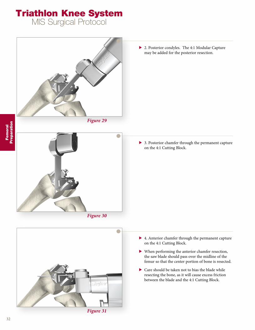
Figure 29
Figure 30
Figure 31
> 2 . Posterior condyles . The 4:1 Modular Capture may be added for the posterior resection .
32
> 3 . Posterior chamfer through the permanent capture on the 4:1 Cutting Block .
> 4 . Anterior chamfer through the permanent capture on the 4:1 Cutting Block .
> When performing the anterior chamfer resection, the saw blade should pass over the midline of the femur so that the center portion of bone is resected .
> Care should be taken not to bias the blade while resecting the bone, as it will cause excess friction between the blade and the 4:1 Cutting Block .
Triathlon Knee SystemMIS Surgical Protocol
Fem
ora
lP
repara
tion

Figure 35
PS Box Preparation
> If the surgeon has chosen a PS knee, then the intercondylar notch must be resected . In order to accomplish this, the PS box guide is placed onto the distal femur using the femoral trial Impactor/Extractor . Since the width of the distal portion of the guide represents the exact width of the implant, it should be centered and placed in the desired position flush with the distal resection . The box guide is then pinned to the femur using the headless pins through one of the holes on the anterior surface, as well as one of the holes on the distal surface of the cutting guide .
Figure 32
Instrument Bar
33
> Remove the 4:1 Cutting Block .
> If preparing for a Cruciate Retaining Knee, where no PS box preparation is needed, proceed to Femoral Trial Assessment on page 36 .
Fem
ora
lP
repara
tion
# 1 - 6541-5-701# 2 - 6541-5-702# 3 - 6541-5-703# 4 - 6541-5-704# 5 - 6541-5-705# 6 - 6541-5-706# 7 - 6541-5-707# 8 - 6541-5-708MIS 4:1 Cutting Block
6541-7-806MIS 4:1 Impactor / Extractor
6541-5-806MIS 4:1 Modular Capture
6541-7-807MIS Femoral Trial Extractor
# 1 - 6541-5-711# 2 - 6541-5-712# 3 - 6541-5-713# 4 - 6541-5-714# 5 - 6541-5-715# 6 - 6541-5-716# 7 - 6541-5-717# 8 - 6541-5-718MIS PS Box Cutting Guide
3 .5’’ - 7650-10382 .5’’ - 7650-1039Headless 1/8’’ Pin
6541-4-804Headless Pin Extractor
Size S - 6541-7-812Size M - 6541-7-813Size L - 6541-7-814Tibial Protector Plate
34
Triathlon Knee SystemMIS Surgical Protocol
Fem
ora
lP
repara
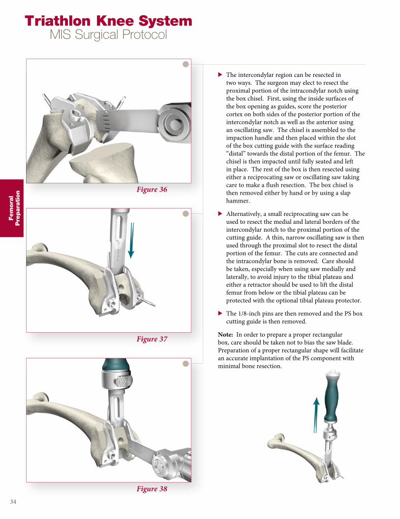
tion Figure 36
Figure 37
Figure 38
> The intercondylar region can be resected in two ways . The surgeon may elect to resect the proximal portion of the intracondylar notch using the box chisel . First, using the inside surfaces of the box opening as guides, score the posterior cortex on both sides of the posterior portion of the intercondylar notch as well as the anterior using an oscillating saw . The chisel is assembled to the impaction handle and then placed within the slot of the box cutting guide with the surface reading “distal” towards the distal portion of the femur . The chisel is then impacted until fully seated and left in place . The rest of the box is then resected using either a reciprocating saw or oscillating saw taking care to make a flush resection . The box chisel is then removed either by hand or by using a slap hammer .
> Alternatively, a small reciprocating saw can be used to resect the medial and lateral borders of the intercondylar notch to the proximal portion of the cutting guide . A thin, narrow oscillating saw is then used through the proximal slot to resect the distal portion of the femur . The cuts are connected and the intracondylar bone is removed . Care should be taken, especially when using saw medially and laterally, to avoid injury to the tibial plateau and either a retractor should be used to lift the distal femur from below or the tibial plateau can be protected with the optional tibial plateau protector .
> The 1/8-inch pins are then removed and the PS box cutting guide is then removed .
Note: In order to prepare a proper rectangular box, care should be taken not to bias the saw blade . Preparation of a proper rectangular shape will facilitate an accurate implantation of the PS component with minimal bone resection .
Instrument Bar
35
Fem
ora
lP
repara
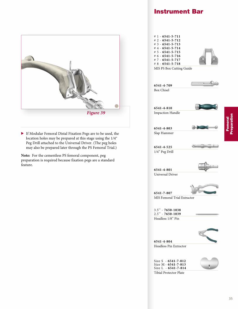
tionFigure 39
> If Modular Femoral Distal Fixation Pegs are to be used, the location holes may be prepared at this stage using the 1/4” Peg Drill attached to the Universal Driver . (The peg holes may also be prepared later through the PS Femoral Trial .)
Note: For the cementless PS femoral component, peg preparation is required because fixation pegs are a standard feature .
# 1 - 6541-5-711# 2 - 6541-5-712# 3 - 6541-5-713# 4 - 6541-5-714# 5 - 6541-5-715# 6 - 6541-5-716# 7 - 6541-5-717# 8 - 6541-5-718MIS PS Box Cutting Guide
6541-4-709Box Chisel
6541-4-810Impaction Handle
6541-4-803Slap Hammer
6541-4-5251/4” Peg Drill
6541-4-801Universal Driver
6541-7-807MIS Femoral Trial Extractor
3 .5’’ - 7650-10382 .5’’ - 7650-1039Headless 1/8’’ Pin
6541-4-804Headless Pin Extractor
Size S - 6541-7-812Size M - 6541-7-813Size L - 6541-7-814Tibial Protector Plate
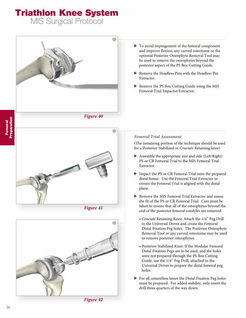
Figure 40
Figure 41
Figure 42
> To avoid impingement of the femoral component and improve flexion, any curved osteotome or the optional Posterior Osteophyte Removal Tool may be used to remove the osteophytes beyond the posterior aspect of the PS Box Cutting Guide .
> Remove the Headless Pins with the Headless Pin Extractor .
> Remove the PS Box Cutting Guide using the MIS Femoral Trial Impactor/Extractor .
36
Femoral Trial Assessment(The remaining portion of the technique should be used for a Posterior Stabilized or Cruciate Retaining knee)
> Assemble the appropriate size and side (Left/Right) PS or CR Femoral Trial to the MIS Femoral Trial Extractor .
> Impact the PS or CR Femoral Trial onto the prepared distal femur . Use the Femoral Trial Extractor to ensure the Femoral Trial is aligned with the distal plane .
> Remove the MIS Femoral Trial Extractor and assess the fit of the PS or CR Femoral Trial . Care must be taken to ensure that all of the osteophytes beyond the end of the posterior femoral condyles are removed .
• Cruciate Retaining Knee: Attach the 1/4” Peg Drill to the Universal Driver and create the Femoral Distal Fixation Peg holes . The Posterior Osteophyte Removal Tool or any curved osteotome may be used to remove posterior osteophytes .
• Posterior Stabilized Knee: If the Modular Femoral Distal Fixation Pegs are to be used, and the holes were not prepared through the PS Box Cutting Guide, use the 1/4’’ Peg Drill, attached to the Universal Driver to prepare the distal femoral peg holes .
> For all cementless knees the Distal Fixation Peg holes must be prepared . For added stability, only insert the drill three quarters of the way down .
Triathlon Knee SystemMIS Surgical Protocol
Fem
ora
lP
repara
tion
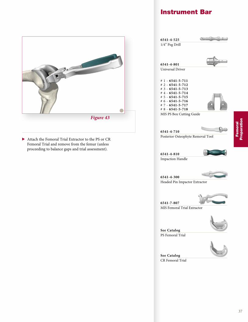
Figure 43
Instrument Bar
37
> Attach the Femoral Trial Extractor to the PS or CR Femoral Trial and remove from the femur (unless proceeding to balance gaps and trial assessment) .
Fem
ora
lP
repara
tion
6541-4-5251/4” Peg Drill
6541-4-801Universal Driver
# 1 - 6541-5-711# 2 - 6541-5-712# 3 - 6541-5-713# 4 - 6541-5-714# 5 - 6541-5-715# 6 - 6541-5-716# 7 - 6541-5-717# 8 - 6541-5-718MIS PS Box Cutting Guide
6541-4-710Posterior Osteophyte Removal Tool
6541-4-810Impaction Handle
6541-7-807MIS Femoral Trial Extractor
6541-4-300Headed Pin Impactor Extractor
See CatalogPS Femoral Trial
See CatalogCR Femoral Trial
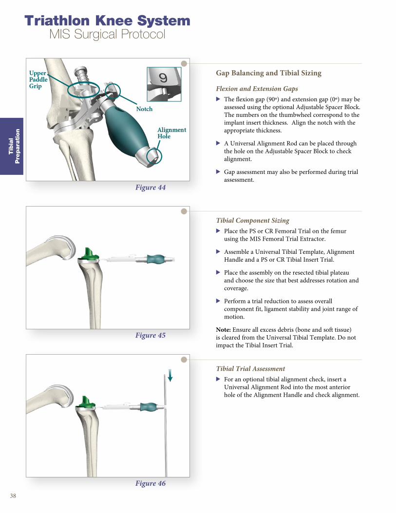
Figure 44
Figure 45
Figure 46
Gap Balancing and Tibial Sizing
Flexion and Extension Gaps> The flexion gap (90º) and extension gap (0º) may be
assessed using the optional Adjustable Spacer Block . The numbers on the thumbwheel correspond to the implant insert thickness . Align the notch with the appropriate thickness .
> A Universal Alignment Rod can be placed through the hole on the Adjustable Spacer Block to check alignment .
> Gap assessment may also be performed during trial assessment .
38
Tibial Component Sizing> Place the PS or CR Femoral Trial on the femur
using the MIS Femoral Trial Extractor .
> Assemble a Universal Tibial Template, Alignment Handle and a PS or CR Tibial Insert Trial .
> Place the assembly on the resected tibial plateau and choose the size that best addresses rotation and coverage .
> Perform a trial reduction to assess overall component fit, ligament stability and joint range of motion .
Note: Ensure all excess debris (bone and soft tissue) is cleared from the Universal Tibial Template . Do not impact the Tibial Insert Trial .
Tibial Trial Assessment> For an optional tibial alignment check, insert a
Universal Alignment Rod into the most anterior hole of the Alignment Handle and check alignment .
Triathlon Knee SystemMIS Surgical Protocol
Tib
ial
Pre
para
tion
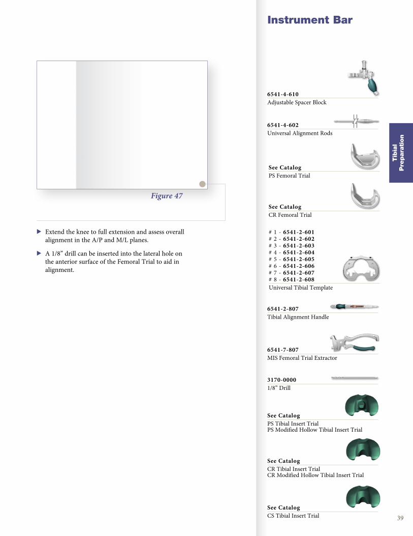
Figure 47
Instrument Bar
39
> Extend the knee to full extension and assess overall alignment in the A/P and M/L planes .
> A 1/8” drill can be inserted into the lateral hole on the anterior surface of the Femoral Trial to aid in alignment .
Tib
ial
Pre
para
tion
6541-4-610Adjustable Spacer Block
6541-4-602Universal Alignment Rods
See CatalogPS Femoral Trial
See CatalogCR Femoral Trial
# 1 - 6541-2-601# 2 - 6541-2-602# 3 - 6541-2-603# 4 - 6541-2-604# 5 - 6541-2-605# 6 - 6541-2-606# 7 - 6541-2-607# 8 - 6541-2-608Universal Tibial Template
6541-2-807Tibial Alignment Handle
6541-7-807MIS Femoral Trial Extractor
3170-00001/8” Drill
See CatalogPS Tibial Insert TrialPS Modified Hollow Tibial Insert Trial
See CatalogCR Tibial Insert TrialCR Modified Hollow Tibial Insert Trial
See CatalogCS Tibial Insert Trial
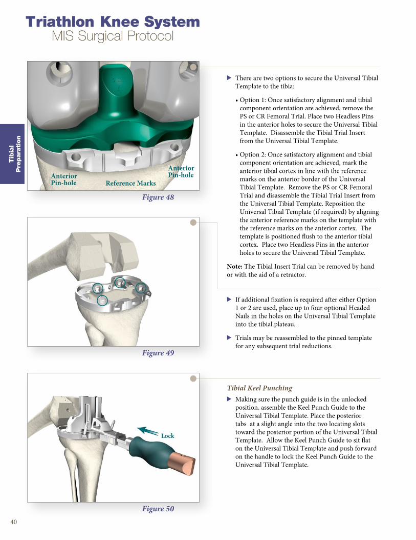
Figure 48
Figure 49
Figure 50
> There are two options to secure the Universal Tibial Template to the tibia:
• Option 1: Once satisfactory alignment and tibial component orientation are achieved, remove the PS or CR Femoral Trial . Place two Headless Pins in the anterior holes to secure the Universal Tibial Template . Disassemble the Tibial Trial Insert from the Universal Tibial Template .
• Option 2: Once satisfactory alignment and tibial component orientation are achieved, mark the anterior tibial cortex in line with the reference marks on the anterior border of the Universal Tibial Template . Remove the PS or CR Femoral Trial and disassemble the Tibial Trial Insert from the Universal Tibial Template . Reposition the Universal Tibial Template (if required) by aligning the anterior reference marks on the template with the reference marks on the anterior cortex . The template is positioned flush to the anterior tibial cortex . Place two Headless Pins in the anterior holes to secure the Universal Tibial Template .
Note: The Tibial Insert Trial can be removed by hand or with the aid of a retractor .
40
> If additional fixation is required after either Option 1 or 2 are used, place up to four optional Headed Nails in the holes on the Universal Tibial Template into the tibial plateau .
> Trials may be reassembled to the pinned template for any subsequent trial reductions .
Tibial Keel Punching> Making sure the punch guide is in the unlocked
position, assemble the Keel Punch Guide to the Universal Tibial Template . Place the posterior tabs at a slight angle into the two locating slots toward the posterior portion of the Universal Tibial Template . Allow the Keel Punch Guide to sit flat on the Universal Tibial Template and push forward on the handle to lock the Keel Punch Guide to the Universal Tibial Template .
Triathlon Knee SystemMIS Surgical Protocol
Tib
ial
Pre
para
tion
AnteriorPin-hole
AnteriorPin-hole
Reference Marks
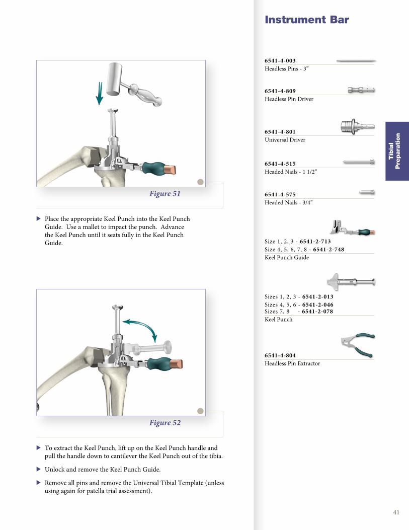
Figure 51
Instrument Bar
41
> Place the appropriate Keel Punch into the Keel Punch Guide . Use a mallet to impact the punch . Advance the Keel Punch until it seats fully in the Keel Punch Guide .
Figure 52
> To extract the Keel Punch, lift up on the Keel Punch handle and pull the handle down to cantilever the Keel Punch out of the tibia .
> Unlock and remove the Keel Punch Guide .
> Remove all pins and remove the Universal Tibial Template (unless using again for patella trial assessment) .
Tib
ial
Pre
para
tion
6541-4-003Headless Pins - 3”
6541-4-809Headless Pin Driver
6541-4-801Universal Driver
6541-4-575Headed Nails - 3/4”
6541-4-515Headed Nails - 1 1/2”
Size 1, 2, 3 - 6541-2-713Size 4, 5, 6, 7, 8 - 6541-2-748Keel Punch Guide
Sizes 1, 2, 3 - 6541-2-013Sizes 4, 5, 6 - 6541-2-046Sizes 7, 8 - 6541-2-078Keel Punch
6541-4-804Headless Pin Extractor
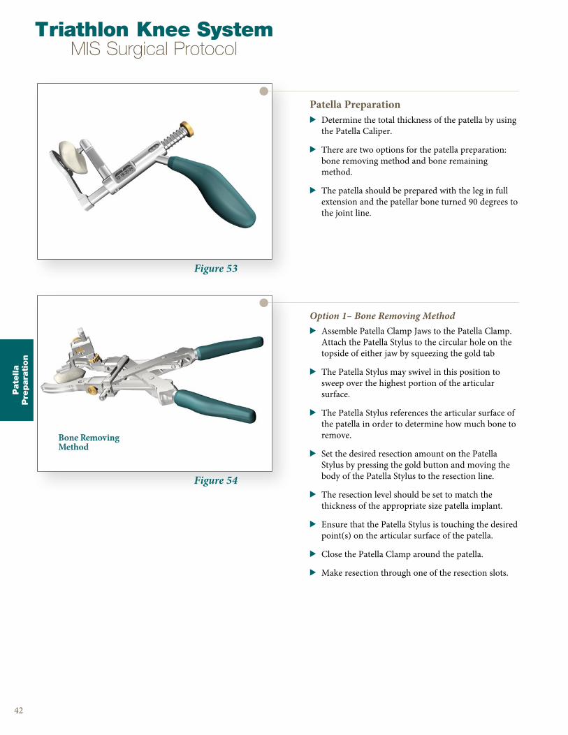
Figure 53
Figure 54
Patella Preparation> Determine the total thickness of the patella by using
the Patella Caliper .
> There are two options for the patella preparation: bone removing method and bone remaining method .
> The patella should be prepared with the leg in full extension and the patellar bone turned 90 degrees to the joint line .
42
Option 1– Bone Removing Method> Assemble Patella Clamp Jaws to the Patella Clamp .
Attach the Patella Stylus to the circular hole on the topside of either jaw by squeezing the gold tab
> The Patella Stylus may swivel in this position to sweep over the highest portion of the articular surface .
> The Patella Stylus references the articular surface of the patella in order to determine how much bone to remove .
> Set the desired resection amount on the Patella Stylus by pressing the gold button and moving the body of the Patella Stylus to the resection line .
> The resection level should be set to match the thickness of the appropriate size patella implant .
> Ensure that the Patella Stylus is touching the desired point(s) on the articular surface of the patella .
> Close the Patella Clamp around the patella .
> Make resection through one of the resection slots .
Triathlon Knee SystemMIS Surgical Protocol
Pate
lla
Pre
para
tion
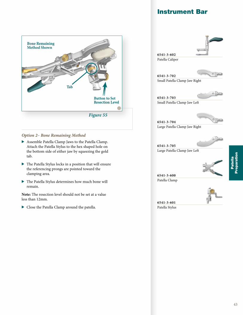
Figure 55
Instrument Bar
43
Option 2– Bone Remaining Method> Assemble Patella Clamp Jaws to the Patella Clamp .
Attach the Patella Stylus to the hex shaped hole on the bottom side of either jaw by squeezing the gold tab .
> The Patella Stylus locks in a position that will ensure the referencing prongs are pointed toward the clamping area .
> The Patella Stylus determines how much bone will remain .
Note: The resection level should not be set at a value less than 12mm .
> Close the Patella Clamp around the patella .
Pate
lla
Pre
para
tion
6541-3-602Patella Caliper
6541-3-702Small Patella Clamp Jaw Right
6541-3-703Small Patella Clamp Jaw Left
6541-3-704Large Patella Clamp Jaw Right
6541-3-705Large Patella Clamp Jaw Left
6541-3-600Patella Clamp
6541-3-601Patella Stylus
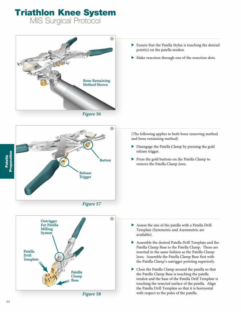
Figure 56
Figure 57
Figure 58
> Ensure that the Patella Stylus is touching the desired point(s) on the patella tendon .
> Make resection through one of the resection slots .
44
(The following applies to both bone removing method and bone remaining method)
> Disengage the Patella Clamp by pressing the gold release trigger .
> Press the gold buttons on the Patella Clamp to remove the Patella Clamp Jaws .
> Assess the size of the patella with a Patella Drill Template (Symmetric and Asymmetric are available) .
> Assemble the desired Patella Drill Template and the Patella Clamp Base to the Patella Clamp . These are inserted in the same fashion as the Patella Clamp Jaws . Assemble the Patella Clamp Base first with the Patella Clamp’s outrigger pointing superiorly .
> Close the Patella Clamp around the patella so that the Patella Clamp Base is touching the patella tendon and the base of the Patella Drill Template is touching the resected surface of the patella . Align the Patella Drill Template so that it is horizontal with respect to the poles of the patella .
Triathlon Knee SystemMIS Surgical Protocol
Pate
lla
Pre
para
tion

Figure 59
Instrument Bar
45
> Attach the All Poly Patella Drill with Stop or the Metal Back Patella Drill (for cementless patella) to the Universal Driver and drill through each fixation peg hole of the Patella Drill Template .
> Disengage the Patella Clamp by pressing the release trigger . Press the gold buttons on the Patella Clamp to remove the Patella Template .
Figure 60
Patella Trial Assessment> Remove any residual cartilage and wash away all debris . Place
correct size Patella Trial (Symmetric or Asymmetric) onto the prepared patella .
> Replace all Trials and assess patellar tracking by taking the knee through a ROM .
Pate
lla
Pre
para
tion
27mm - 6541-3-62729mm - 6541-3-62931mm - 6541-3-63133mm - 6541-3-63336mm - 6541-3-63639mm - 6541-3-639Symmetric Patella Drill Template
29mm - 6541-3-61732mm - 6541-3-61835mm - 6541-3-61938mm - 6541-3-62040mm - 6541-3-621Asymmetric Patella Drill Template
6541-3-801Patella Clamp Base
6541-3-600Patella Clamp
6541-3-524All-Poly Patella Drill w/Stop
6541-4-801Universal Driver
See CatalogSymmetric Patella Trial
See CatalogAsymmetric Patella Trial
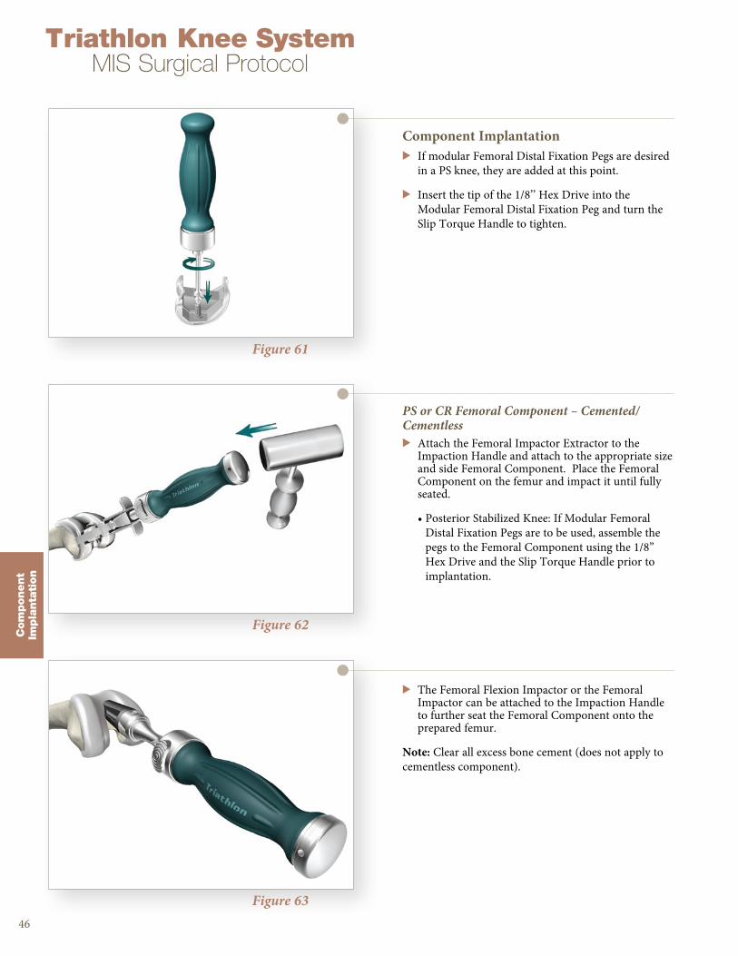
Figure 61
Figure 62
Figure 63
Component Implantation> If modular Femoral Distal Fixation Pegs are desired
in a PS knee, they are added at this point .
> Insert the tip of the 1/8’’ Hex Drive into the Modular Femoral Distal Fixation Peg and turn the Slip Torque Handle to tighten .
46
PS or CR Femoral Component – Cemented/Cementless> Attach the Femoral Impactor Extractor to the
Impaction Handle and attach to the appropriate size and side Femoral Component . Place the Femoral Component on the femur and impact it until fully seated .
• Posterior Stabilized Knee: If Modular Femoral Distal Fixation Pegs are to be used, assemble the pegs to the Femoral Component using the 1/8” Hex Drive and the Slip Torque Handle prior to implantation .
> The Femoral Flexion Impactor or the Femoral Impactor can be attached to the Impaction Handle to further seat the Femoral Component onto the prepared femur .
Note: Clear all excess bone cement (does not apply to cementless component) .
Triathlon Knee SystemMIS Surgical Protocol
Com
ponent
Impla
nta
tion
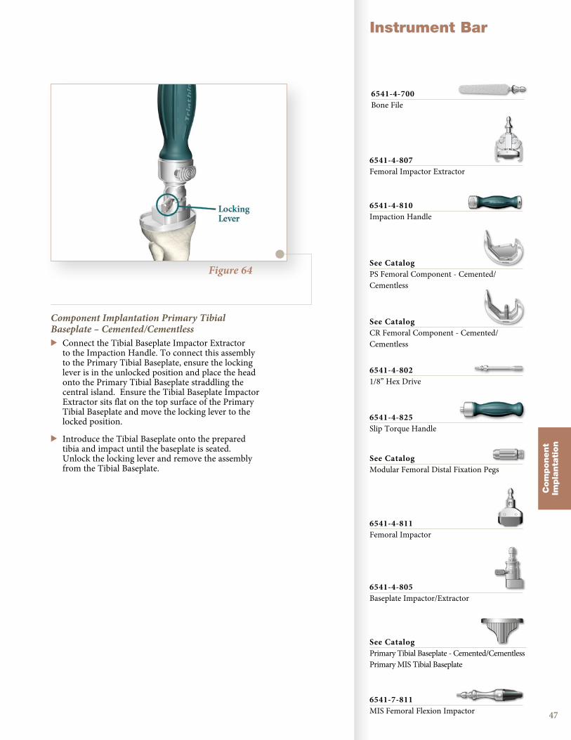
Figure 64
Instrument Bar
47
Component Implantation Primary Tibial Baseplate – Cemented/Cementless> Connect the Tibial Baseplate Impactor Extractor
to the Impaction Handle . To connect this assembly to the Primary Tibial Baseplate, ensure the locking lever is in the unlocked position and place the head onto the Primary Tibial Baseplate straddling the central island . Ensure the Tibial Baseplate Impactor Extractor sits flat on the top surface of the Primary Tibial Baseplate and move the locking lever to the locked position .
> Introduce the Tibial Baseplate onto the prepared tibia and impact until the baseplate is seated . Unlock the locking lever and remove the assembly from the Tibial Baseplate .
Com
ponent
Impla
nta
tion
6541-4-700Bone File
6541-4-807Femoral Impactor Extractor
6541-4-810Impaction Handle
See CatalogPS Femoral Component - Cemented/Cementless
See CatalogCR Femoral Component - Cemented/Cementless
6541-4-8021/8” Hex Drive
6541-4-825Slip Torque Handle
See CatalogModular Femoral Distal Fixation Pegs
6541-4-805Baseplate Impactor/Extractor
See CatalogPrimary Tibial Baseplate - Cemented/CementlessPrimary MIS Tibial Baseplate
6541-4-811Femoral Impactor
6541-7-811MIS Femoral Flexion Impactor

Figure 65
Figure 67
Figure 66
> To further seat the baseplate, attach the Tibial Baseplate Impactor to the Impaction Handle .
> Place the Tibial Baseplate Impactor on to the Primary Tibial Baseplate straddling the central island .
> Ensure the Tibial Baseplate Impactor sits flat on the top surface of the Primary Tibial Baseplate .
> Impact until the Primary Tibial Baseplate is fully seated .
Note: Clear all excess bone cement (does not apply to cementless component) while maintaining position of the Tibial Baseplate .
48
Tibial Insert > Prior to assembly of the Tibial Insert, the Tibial
Trial Insert may be placed on the Tibial Baseplate to once more assess joint stability and range of motion .
> To assemble the Tibial Insert, distract the joint and angle the insert posteriorly into the Tibial Baseplate . The posterior lip of the Tibial Insert must fit beneath the lip on the posterior Tibial Baseplate wall .
> Attach the Tibial Insert Impactor to the Impaction Handle and impact to snap the Insert in place anteriorly . The Tibial Insert is fully seated once the locking wire locks under the barbs on the anterior/interior surface of the Tibial Baseplate wall .
Symmetric or Asymmetric Patella > Assemble the Patella Cement Cap and the Patella
Clamp Base to the Patella Clamp .
Note: In cementless scenarios, if necessary, use a curette to mark the locations of the fixation peg holes .
> Place the Patella Component onto the prepared patella, making certain the fixation peg holes are aligned to the corresponding holes .
> Seat the Patella Component onto the prepared patella by clamping the Patella Cement Cap, Patella Clamp Base and Patella Clamp assembly .
Note: Ensure that the silicon O-ring of the Patella Cement Cap is placed on the articulating surface of the Patella Component .
Note: Leave the assembly clamped to the patella while excess cement is cleared and polymerization is complete .
> Disengage the Patella Clamp by pressing the gold release trigger .
Triathlon Knee SystemMIS Surgical Protocol
Com
ponent
Impla
nta
tion
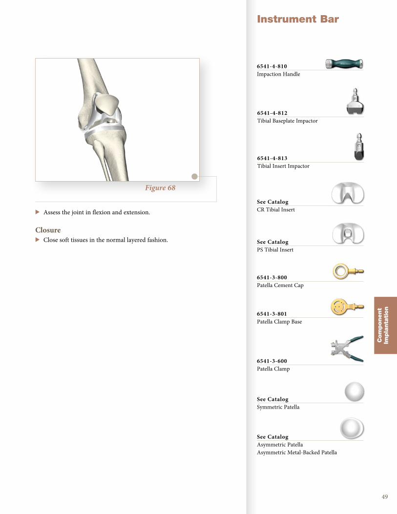
Figure 68
Instrument Bar
49
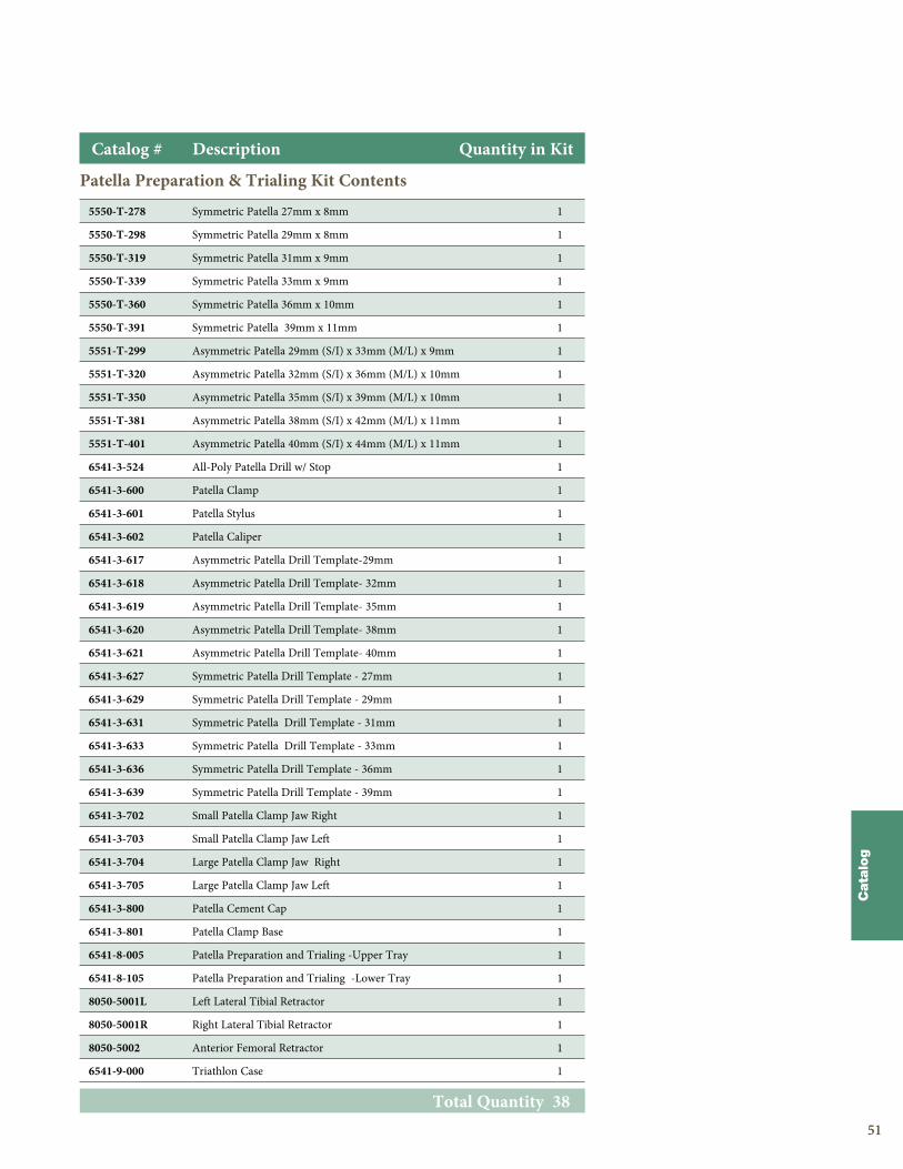
> Assess the joint in flexion and extension .
Closure> Close soft tissues in the normal layered fashion .
Com
ponent
Impla
nta
tion
6541-4-810Impaction Handle
6541-4-812Tibial Baseplate Impactor
6541-4-813Tibial Insert Impactor
See CatalogPS Tibial Insert
See CatalogCR Tibial Insert
6541-3-800Patella Cement Cap
6541-3-801Patella Clamp Base
See CatalogSymmetric Patella
See CatalogAsymmetric PatellaAsymmetric Metal-Backed Patella
6541-3-600Patella Clamp

5050
Triathlon Knee SystemMIS Surgical Protocol
Cata
log
5050
MIS Miscellaneous Instruments Kit Contents
Total Quantity 36
Catalog # Description Quantity in Kit
3170-0000 1/8” Drill 1
6541-4-003 Headless pin- 3” 1
6541-4-300 Headed Pin Impactor Extractor 1
6541-4-400 Bladerunner 1
6541-4-515 Headed Nails- 1 1/2” 2
6541-4-516 5/16” IM Rod 1
6541-4-518 1/8” Peg Drill 1
6541-4-525 1/4” Peg Drill 1
6541-4-538 3/8” IM Drill 1
6541-4-575 Headed Nail- 3/4” 2
6541-4-602 Universal Alignment Rod 2
6541-4-610 Adjustable Spacer Block 1
6541-4-700 Bone File 1
6541-4-709 Box Chisel 1
6541-4-710 Posterior osteophyte removal tool 1
6541-4-800 T- Handle Driver 1
6541-4-801 Universal Driver 1
6541-4-802 1/8” Hex Drive 1
6541-4-803 Slap Hammer 1
6541-4-804 Headless Pin Extractor 1
6541-4-805 Baseplate Impactor Extractor 1
6541-4-806 Universal Alignment Handle 1
6541-4-807 Femoral Impactor Extractor 1
6541-4-809 Headless Pin Driver 1
6541-4-810 Impaction Handle 2
6541-4-811 Femoral Impactor 1
6541-4-812 Tibial Baseplate Impactor 1
6541-4-813 Tibial Insert Impactor 1
6541-4-825 Slip Torque handle 1
6541-8-004 Miscellaneous Instruments- Upper Tray 1
6541-8-104 Miscellaneous Instruments - Lower Tray 1
6541-9-000 Triathlon Case 1
5151
Patella Preparation & Trialing Kit Contents
Total Quantity 38
Catalog # Description Quantity in Kit
5550-T-278 Symmetric Patella 27mm x 8mm 1
5550-T-298 Symmetric Patella 29mm x 8mm 1
5550-T-319 Symmetric Patella 31mm x 9mm 1
5550-T-339 Symmetric Patella 33mm x 9mm 1
5550-T-360 Symmetric Patella 36mm x 10mm 1
5550-T-391 Symmetric Patella 39mm x 11mm 1
5551-T-299 Asymmetric Patella 29mm (S/I) x 33mm (M/L) x 9mm 1
5551-T-320 Asymmetric Patella 32mm (S/I) x 36mm (M/L) x 10mm 1
5551-T-350 Asymmetric Patella 35mm (S/I) x 39mm (M/L) x 10mm 1
5551-T-381 Asymmetric Patella 38mm (S/I) x 42mm (M/L) x 11mm 1
5551-T-401 Asymmetric Patella 40mm (S/I) x 44mm (M/L) x 11mm 1
6541-3-524 All-Poly Patella Drill w/ Stop 1
6541-3-600 Patella Clamp 1
6541-3-601 Patella Stylus 1
6541-3-602 Patella Caliper 1
6541-3-617 Asymmetric Patella Drill Template-29mm 1
6541-3-618 Asymmetric Patella Drill Template- 32mm 1
6541-3-619 Asymmetric Patella Drill Template- 35mm 1
6541-3-620 Asymmetric Patella Drill Template- 38mm 1
6541-3-621 Asymmetric Patella Drill Template- 40mm 1
6541-3-627 Symmetric Patella Drill Template - 27mm 1
6541-3-629 Symmetric Patella Drill Template - 29mm 1
6541-3-631 Symmetric Patella Drill Template - 31mm 1
6541-3-633 Symmetric Patella Drill Template - 33mm 1
6541-3-636 Symmetric Patella Drill Template - 36mm 1
6541-3-639 Symmetric Patella Drill Template - 39mm 1
6541-3-702 Small Patella Clamp Jaw Right 1
6541-3-703 Small Patella Clamp Jaw Left 1
6541-3-704 Large Patella Clamp Jaw Right 1
6541-3-705 Large Patella Clamp Jaw Left 1
6541-3-800 Patella Cement Cap 1
6541-3-801 Patella Clamp Base 1
6541-8-005 Patella Preparation and Trialing -Upper Tray 1
6541-8-105 Patella Preparation and Trialing -Lower Tray 1
8050-5001L Left Lateral Tibial Retractor 1
8050-5001R Right Lateral Tibial Retractor 1
8050-5002 Anterior Femoral Retractor 1
6541-9-000 Triathlon Case 1
Cata
log
5252
Triathlon Knee SystemMIS Surgical Protocol
Cata
log
5252
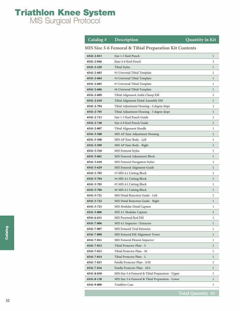
MIS Size 3-6 Femoral & Tibial Preparation Kit Contents
Total Quantity 43
Catalog # Description Quantity in Kit
6541-2-013 Size 1-3 Keel Punch 1
6541-2-046 Sizer 4-6 Keel Punch 1
6541-2-429 Tibial Stylus 1
6541-2-603 #3 Universal Tibial Template 1
6541-2-604 #4 Universal Tibial Template 1
6541-2-605 #5 Universal Tibial Template 1
6541-2-606 #6 Universal Tibial Template 1
6541-2-609 Tibial Alignment Ankle Clamp EM 1
6541-2-610 Tibial Alignment Distal Assembly EM 1
6541-2-704 Tibial Adjustment Housing - 0 degree slope 1
6541-2-705 Tibial Adjustment Housing - 3 degree slope 1
6541-2-713 Size 1-3 Keel Punch Guide 1
6541-2-748 Size 4-8 Keel Punch Guide 1
6541-2-807 Tibial Alignment Handle 1
6541-5-500 MIS AP Sizer Adjustment Housing 1
6541-5-508 MIS AP Sizer Body - Left 1
6541-5-509 MIS AP Sizer Body - Right 1
6541-5-510 MIS Femoral Stylus 1
6541-5-601 MIS Femoral Adjustment Block 1
6541-5-610 MIS Femoral Navigation Stylus 1
6541-5-629 MIS Femoral Alignment Guide 1
6541-5-703 #3 MIS 4:1 Cutting Block 1
6541-5-704 #4 MIS 4:1 Cutting Block 1
6541-5-705 #5 MIS 4:1 Cutting Block 1
6541-5-706 #6 MIS 4:1 Cutting Block 1
6541-5-721 MIS Distal Resection Guide - Left 1
6541-5-722 MIS Distal Resection Guide - Right 1
6541-5-723 MIS Modular Distal Capture 1
6541-5-806 MIS 4:1 Modular Capture 2
6541-6-611 MIS Proximal Rod EM 1
6541-7-806 MIS 4:1 Impactor / Extractor 1
6541-7-807 MIS Femoral Trial Extractor 1
6541-7-808 MIS Femoral EM Alignment Tower 1
6541-7-811 MIS Femoral Flexion Impactor 1
6541-7-812 Tibial Protector Plate - S 1
6541-7-813 Tibial Protector Plate - M 1
6541-7-814 Tibial Protector Plate - L 1
6541-7-815 Patella Protector Plate - S/M 1
6541-7-816 Patella Protector Plate - M/L 1
6541-8-030 MIS Size 3-6 Femoral & Tibial Preparation - Upper 1
6541-8-130 MIS Size 3-6 Femoral & Tibial Preparation - Lower 1
6541-9-000 Triathlon Case 1
5353
Cata
log
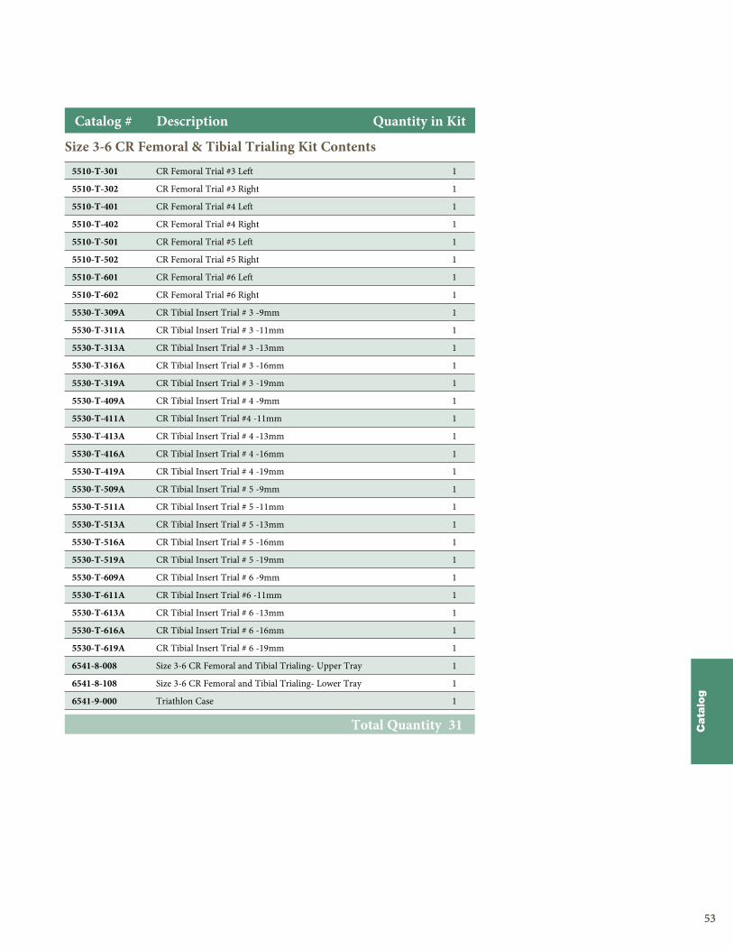
Size 3-6 CR Femoral & Tibial Trialing Kit Contents
Catalog # Description Quantity in Kit
Total Quantity 31
5510-T-301 CR Femoral Trial #3 Left 1
5510-T-302 CR Femoral Trial #3 Right 1
5510-T-401 CR Femoral Trial #4 Left 1
5510-T-402 CR Femoral Trial #4 Right 1
5510-T-501 CR Femoral Trial #5 Left 1
5510-T-502 CR Femoral Trial #5 Right 1
5510-T-601 CR Femoral Trial #6 Left 1
5510-T-602 CR Femoral Trial #6 Right 1
5530-T-309A CR Tibial Insert Trial # 3 -9mm 1
5530-T-311A CR Tibial Insert Trial # 3 -11mm 1
5530-T-313A CR Tibial Insert Trial # 3 -13mm 1
5530-T-316A CR Tibial Insert Trial # 3 -16mm 1
5530-T-319A CR Tibial Insert Trial # 3 -19mm 1
5530-T-409A CR Tibial Insert Trial # 4 -9mm 1
5530-T-411A CR Tibial Insert Trial #4 -11mm 1
5530-T-413A CR Tibial Insert Trial # 4 -13mm 1
5530-T-416A CR Tibial Insert Trial # 4 -16mm 1
5530-T-419A CR Tibial Insert Trial # 4 -19mm 1
5530-T-509A CR Tibial Insert Trial # 5 -9mm 1
5530-T-511A CR Tibial Insert Trial # 5 -11mm 1
5530-T-513A CR Tibial Insert Trial # 5 -13mm 1
5530-T-516A CR Tibial Insert Trial # 5 -16mm 1
5530-T-519A CR Tibial Insert Trial # 5 -19mm 1
5530-T-609A CR Tibial Insert Trial # 6 -9mm 1
5530-T-611A CR Tibial Insert Trial #6 -11mm 1
5530-T-613A CR Tibial Insert Trial # 6 -13mm 1
5530-T-616A CR Tibial Insert Trial # 6 -16mm 1
5530-T-619A CR Tibial Insert Trial # 6 -19mm 1
6541-8-008 Size 3-6 CR Femoral and Tibial Trialing- Upper Tray 1
6541-8-108 Size 3-6 CR Femoral and Tibial Trialing- Lower Tray 1
6541-9-000 Triathlon Case 1
5454
Triathlon Knee SystemMIS Surgical Protocol
Cata
log
5454
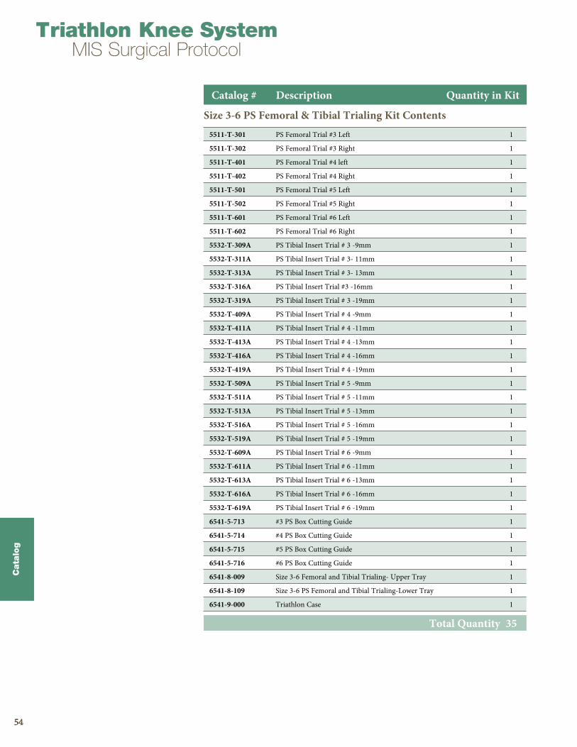
Size 3-6 PS Femoral & Tibial Trialing Kit Contents
Total Quantity 35
Catalog # Description Quantity in Kit
5511-T-301 PS Femoral Trial #3 Left 1
5511-T-302 PS Femoral Trial #3 Right 1
5511-T-401 PS Femoral Trial #4 left 1
5511-T-402 PS Femoral Trial #4 Right 1
5511-T-501 PS Femoral Trial #5 Left 1
5511-T-502 PS Femoral Trial #5 Right 1
5511-T-601 PS Femoral Trial #6 Left 1
5511-T-602 PS Femoral Trial #6 Right 1
5532-T-309A PS Tibial Insert Trial # 3 -9mm 1
5532-T-311A PS Tibial Insert Trial # 3- 11mm 1
5532-T-313A PS Tibial Insert Trial # 3- 13mm 1
5532-T-316A PS Tibial Insert Trial #3 -16mm 1
5532-T-319A PS Tibial Insert Trial # 3 -19mm 1
5532-T-409A PS Tibial Insert Trial # 4 -9mm 1
5532-T-411A PS Tibial Insert Trial # 4 -11mm 1
5532-T-413A PS Tibial Insert Trial # 4 -13mm 1
5532-T-416A PS Tibial Insert Trial # 4 -16mm 1
5532-T-419A PS Tibial Insert Trial # 4 -19mm 1
5532-T-509A PS Tibial Insert Trial # 5 -9mm 1
5532-T-511A PS Tibial Insert Trial # 5 -11mm 1
5532-T-513A PS Tibial Insert Trial # 5 -13mm 1
5532-T-516A PS Tibial Insert Trial # 5 -16mm 1
5532-T-519A PS Tibial Insert Trial # 5 -19mm 1
5532-T-609A PS Tibial Insert Trial # 6 -9mm 1
5532-T-611A PS Tibial Insert Trial # 6 -11mm 1
5532-T-613A PS Tibial Insert Trial # 6 -13mm 1
5532-T-616A PS Tibial Insert Trial # 6 -16mm 1
5532-T-619A PS Tibial Insert Trial # 6 -19mm 1
6541-5-713 #3 PS Box Cutting Guide 1
6541-5-714 #4 PS Box Cutting Guide 1
6541-5-715 #5 PS Box Cutting Guide 1
6541-5-716 #6 PS Box Cutting Guide 1
6541-8-009 Size 3-6 Femoral and Tibial Trialing- Upper Tray 1
6541-8-109 Size 3-6 PS Femoral and Tibial Trialing-Lower Tray 1
6541-9-000 Triathlon Case 1
5555
Cata
log
Catalog # Description Quantity in Kit
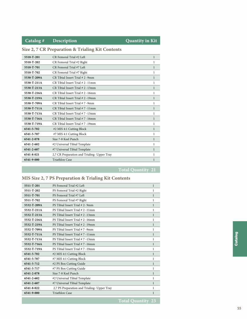
Size 2, 7 CR Preparation & Trialing Kit Contents
Total Quantity 21
5510-T-201 CR Femoral Trial #2 Left 15510-T-202 CR Femoral Trial #2 Right 15510-T-701 CR Femoral Trial #7 Left 15510-T-702 CR Femoral Trial #7 Right 15530-T-209A CR Tibial Insert Trial # 2 -9mm 15530-T-211A CR Tibial Insert Trial # 2 -11mm 15530-T-213A CR Tibial Insert Trial # 2 -13mm 15530-T-216A CR Tibial Insert Trial # 2 -16mm 15530-T-219A CR Tibial Insert Trial # 2 -19mm 15530-T-709A CR Tibial Insert Trial # 7 -9mm 15530-T-711A CR Tibial Insert Trial # 7 -11mm 15530-T-713A CR Tibial Insert Trial # 7 -13mm 15530-T-716A CR Tibial Insert Trial # 7 -16mm 15530-T-719A CR Tibial Insert Trial # 7 -19mm 16541-5-702 #2 MIS 4:1 Cutting Block 16541-5-707 #7 MIS 4:1 Cutting Block 16541-2-078 Size 7-8 Keel Punch 16541-2-602 #2 Universal Tibial Template 16541-2-607 #7 Universal Tibial Template 16541-8-021 2,7 CR Preparation and Trialing- Upper Tray 16541-9-000 Triathlon Case 1
MIS Size 2, 7 PS Preparation & Trialing Kit Contents
Total Quantity 23
5511-T-201 PS Femoral Trial #2 Left 15511-T-202 PS Femoral Trial #2 Right 15511-T-701 PS Femoral Trial #7 Left 15511-T-702 PS Femoral Trial #7 Right 15532-T-209A PS Tibial Insert Trial # 2- 9mm 15532-T-211A PS Tibial Insert Trial # 2 -11mm 15532-T-213A PS Tibial Insert Trial # 2 -13mm 15532-T-216A PS Tibial Insert Trial # 2 -16mm 15532-T-219A PS Tibial Insert Trial # 2 -19mm 15532-T-709A PS Tibial Insert Trial # 7 -9mm 15532-T-711A PS Tibial Insert Trial # 7 -11mm 15532-T-713A PS Tibial Insert Trial # 7 -13mm 15532-T-716A PS Tibial Insert Trial # 7 -16mm 15532-T-719A PS Tibial Insert Trial # 7 -19mm 16541-5-702 #2 MIS 4:1 Cutting Block 16541-5-707 #7 MIS 4:1 Cutting Block 16541-5-712 #2 PS Box Cutting Guide 16541-5-717 #7 PS Box Cutting Guide 16541-2-078 Size 7-8 Keel Punch 16541-2-602 #2 Universal Tibial Template 16541-2-607 #7 Universal Tibial Template 16541-8-022 2,7 PS Preparation and Trialing- Upper Tray 16541-9-000 Triathlon Case 1
5656
Triathlon Knee SystemMIS Surgical Protocol
Cata
log
5656
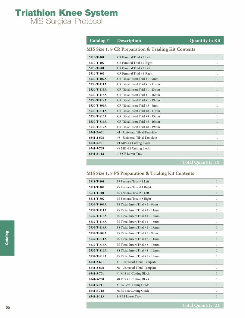
MIS Size 1, 8 CR Preparation & Trialing Kit Contents
Catalog # Description Quantity in Kit
Total Quantity 19
5510-T-101 CR Femoral Trial # 1 Left 1
5510-T-102 CR Femoral Trial # 1 Right 1
5510-T-801 CR Femoral Trial # 8 Left 1
5510-T-802 CR Femoral Trial # 8 Right 1
5530-T-109A CR Tibial Insert Trial #1 - 9mm 1
5530-T-111A CR Tibial Insert Trial #1 - 11mm 1
5530-T-113A CR Tibial Insert Trial #1 - 13mm 1
5530-T-116A CR Tibial Insert Trial #1 - 16mm 1
5530-T-119A CR Tibial Insert Trial #1 - 19mm 1
5530-T-809A CR Tibial Insert Trial #8 - 9mm 1
5530-T-811A CR Tibial Insert Trial #8 - 11mm 1
5530-T-813A CR Tibial Insert Trial #8 - 13mm 1
5530-T-816A CR Tibial Insert Trial #8 - 16mm 1
5530-T-819A CR Tibial Insert Trial #8 - 19mm 1
6541-2-601 #1 - Universal Tibial Template 1
6541-2-608 #8 - Universal Tibial Template 1
6541-5-701 #1 MIS 4:1 Cutting Block 1
6541-5-708 #8 MIS 4:1 Cutting Block 1
6541-8-112 1-8 CR Lower Tray 1
MIS Size 1, 8 PS Preparation & Trialing Kit Contents
Total Quantity 21
5511-T-101 PS Femoral Trial # 1 Left 1
5511-T-102 PS Femoral Trial # 1 Right 1
5511-T-801 PS Femoral Trial # 8 Left 1
5511-T-802 PS Femoral Trial # 8 Right 1
5532-T-109A PS Tibial Insert Trial # 1 - 9mm 1
5532-T-111A PS Tibial Insert Trial # 1 - 11mm 1
5532-T-113A PS Tibial Insert Trial # 1 - 13mm 1
5532-T-116A PS Tibial Insert Trial # 1 - 16mm 1
5532-T-119A PS Tibial Insert Trial # 1 - 19mm 1
5532-T-809A PS Tibial Insert Trial # 8 - 9mm 1
5532-T-811A PS Tibial Insert Trial # 8 - 11mm 1
5532-T-813A PS Tibial Insert Trial # 8 - 13mm 1
5532-T-816A PS Tibial Insert Trial # 8 - 16mm 1
5532-T-819A PS Tibial Insert Trial # 8 - 19mm 1
6541-2-601 #1 - Universal Tibial Template 1
6541-2-608 #8 - Universal Tibial Template 1
6541-5-701 #1 MIS 4:1 Cutting Block 1
6541-5-708 #8 MIS 4:1 Cutting Block 1
6541-5-711 #1 PS Box Cutting Guide 1
6541-5-718 #8 PS Box Cutting Guide 1
6541-8-113 1-8 PS Lower Tray 1
5757
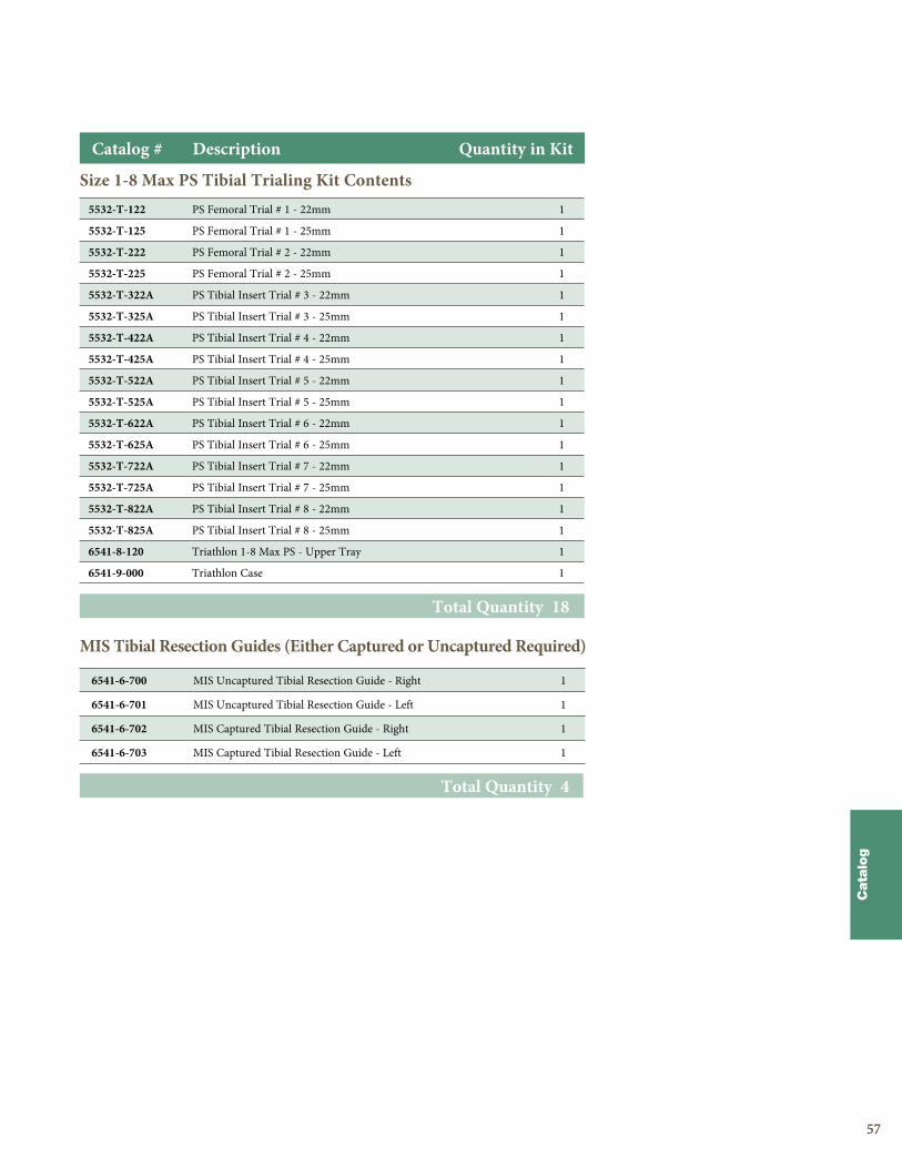
Size 1-8 Max PS Tibial Trialing Kit Contents
Total Quantity 18
5532-T-122 PS Femoral Trial # 1 - 22mm 1
5532-T-125 PS Femoral Trial # 1 - 25mm 1
5532-T-222 PS Femoral Trial # 2 - 22mm 1
5532-T-225 PS Femoral Trial # 2 - 25mm 1
5532-T-322A PS Tibial Insert Trial # 3 - 22mm 1
5532-T-325A PS Tibial Insert Trial # 3 - 25mm 1
5532-T-422A PS Tibial Insert Trial # 4 - 22mm 1
5532-T-425A PS Tibial Insert Trial # 4 - 25mm 1
5532-T-522A PS Tibial Insert Trial # 5 - 22mm 1
5532-T-525A PS Tibial Insert Trial # 5 - 25mm 1
5532-T-622A PS Tibial Insert Trial # 6 - 22mm 1
5532-T-625A PS Tibial Insert Trial # 6 - 25mm 1
5532-T-722A PS Tibial Insert Trial # 7 - 22mm 1
5532-T-725A PS Tibial Insert Trial # 7 - 25mm 1
5532-T-822A PS Tibial Insert Trial # 8 - 22mm 1
5532-T-825A PS Tibial Insert Trial # 8 - 25mm 1
6541-8-120 Triathlon 1-8 Max PS - Upper Tray 1
6541-9-000 Triathlon Case 1
Cata
log
MIS Tibial Resection Guides (Either Captured or Uncaptured Required)
Total Quantity 4
6541-6-700 MIS Uncaptured Tibial Resection Guide - Right 1
6541-6-701 MIS Uncaptured Tibial Resection Guide - Left 1
6541-6-702 MIS Captured Tibial Resection Guide - Right 1
6541-6-703 MIS Captured Tibial Resection Guide - Left 1
Catalog # Description Quantity in Kit
58
Cata
log
Triathlon Knee SystemMIS Surgical Protocol
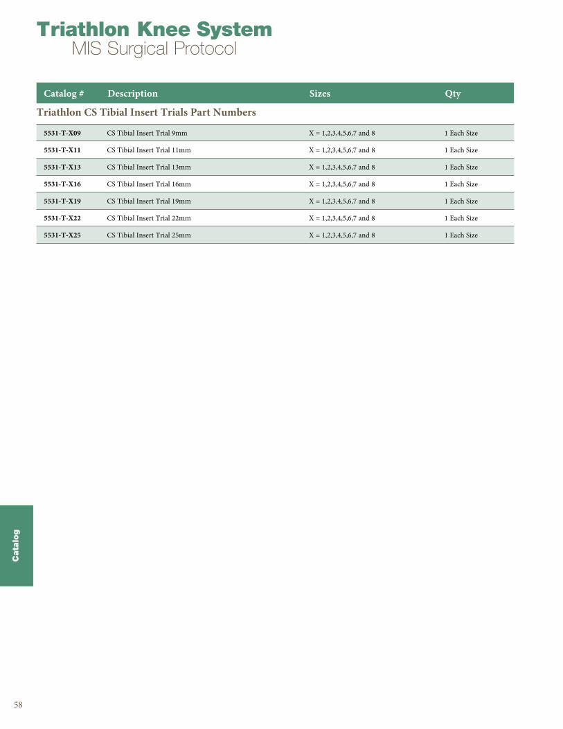
Catalog # Description Sizes Qty
5531-T-X09 CS Tibial Insert Trial 9mm X = 1,2,3,4,5,6,7 and 8 1 Each Size
5531-T-X11 CS Tibial Insert Trial 11mm X = 1,2,3,4,5,6,7 and 8 1 Each Size
5531-T-X13 CS Tibial Insert Trial 13mm X = 1,2,3,4,5,6,7 and 8 1 Each Size
5531-T-X16 CS Tibial Insert Trial 16mm X = 1,2,3,4,5,6,7 and 8 1 Each Size
5531-T-X19 CS Tibial Insert Trial 19mm X = 1,2,3,4,5,6,7 and 8 1 Each Size
5531-T-X22 CS Tibial Insert Trial 22mm X = 1,2,3,4,5,6,7 and 8 1 Each Size
5531-T-X25 CS Tibial Insert Trial 25mm X = 1,2,3,4,5,6,7 and 8 1 Each Size
Triathlon CS Tibial Insert Trials Part Numbers
59
Cata
log
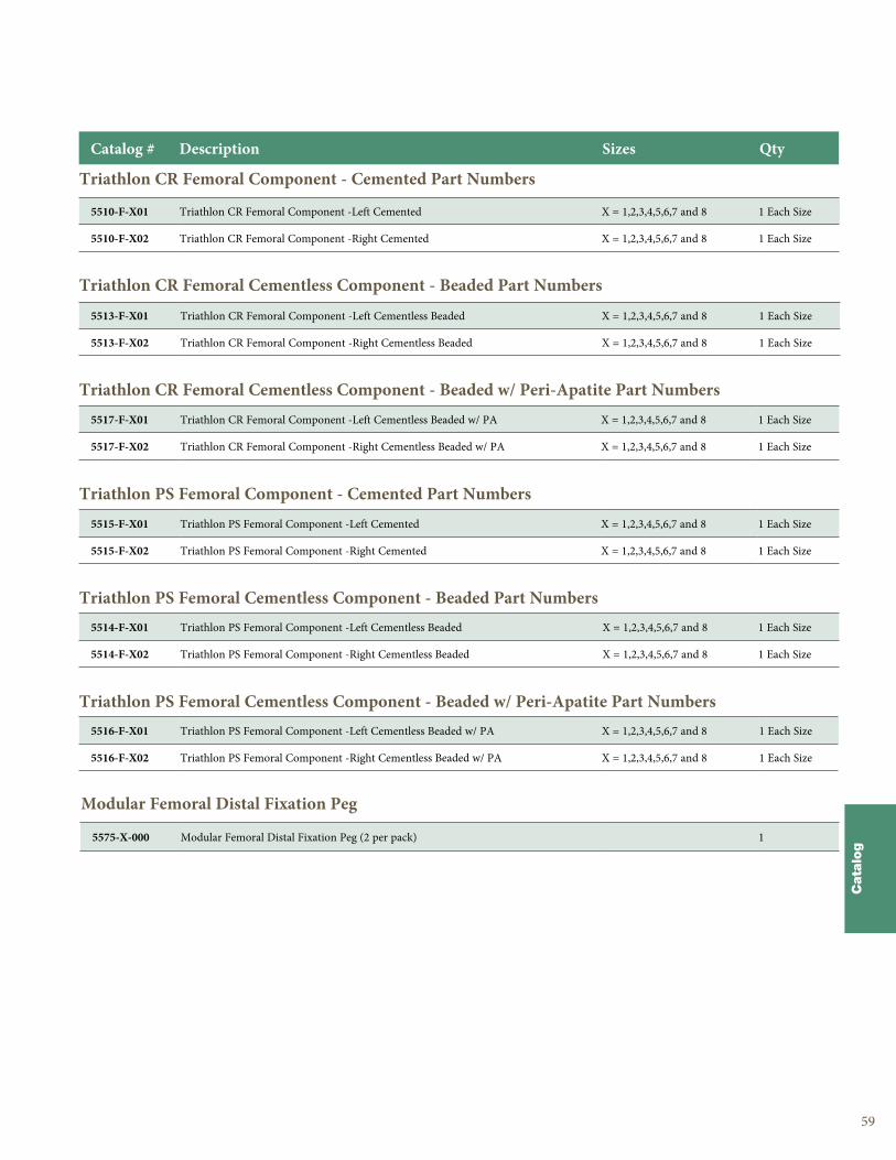
Triathlon CR Femoral Component - Cemented Part Numbers
Triathlon CR Femoral Cementless Component - Beaded Part Numbers
Triathlon CR Femoral Cementless Component - Beaded w/ Peri-Apatite Part Numbers
Triathlon PS Femoral Component - Cemented Part Numbers
Triathlon PS Femoral Cementless Component - Beaded Part Numbers
Triathlon PS Femoral Cementless Component - Beaded w/ Peri-Apatite Part Numbers
Catalog # Description Sizes Qty
5510-F-X01 Triathlon CR Femoral Component -Left Cemented X = 1,2,3,4,5,6,7 and 8 1 Each Size
5510-F-X02 Triathlon CR Femoral Component -Right Cemented X = 1,2,3,4,5,6,7 and 8 1 Each Size
5513-F-X01 Triathlon CR Femoral Component -Left Cementless Beaded X = 1,2,3,4,5,6,7 and 8 1 Each Size
5513-F-X02 Triathlon CR Femoral Component -Right Cementless Beaded X = 1,2,3,4,5,6,7 and 8 1 Each Size
5517-F-X01 Triathlon CR Femoral Component -Left Cementless Beaded w/ PA X = 1,2,3,4,5,6,7 and 8 1 Each Size
5517-F-X02 Triathlon CR Femoral Component -Right Cementless Beaded w/ PA X = 1,2,3,4,5,6,7 and 8 1 Each Size
5515-F-X01 Triathlon PS Femoral Component -Left Cemented X = 1,2,3,4,5,6,7 and 8 1 Each Size
5515-F-X02 Triathlon PS Femoral Component -Right Cemented X = 1,2,3,4,5,6,7 and 8 1 Each Size
5514-F-X01 Triathlon PS Femoral Component -Left Cementless Beaded X = 1,2,3,4,5,6,7 and 8 1 Each Size
5514-F-X02 Triathlon PS Femoral Component -Right Cementless Beaded X = 1,2,3,4,5,6,7 and 8 1 Each Size
5516-F-X01 Triathlon PS Femoral Component -Left Cementless Beaded w/ PA X = 1,2,3,4,5,6,7 and 8 1 Each Size
5516-F-X02 Triathlon PS Femoral Component -Right Cementless Beaded w/ PA X = 1,2,3,4,5,6,7 and 8 1 Each Size
Modular Femoral Distal Fixation Peg
5575-X-000 Modular Femoral Distal Fixation Peg (2 per pack) 1
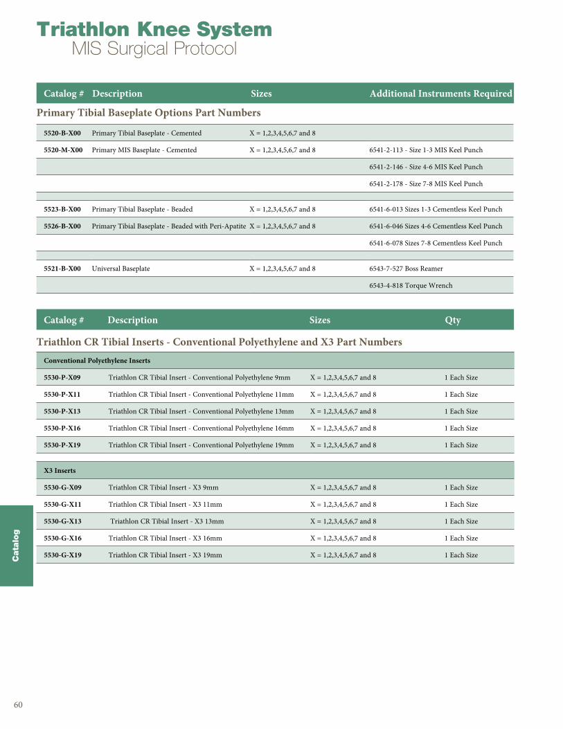
60
Cata
log
Triathlon Knee SystemMIS Surgical Protocol
Primary Tibial Baseplate Options Part Numbers
Triathlon CR Tibial Inserts - Conventional Polyethylene and X3 Part Numbers
Catalog # Description Sizes Additional Instruments Required
5520-B-X00 Primary Tibial Baseplate - Cemented X = 1,2,3,4,5,6,7 and 8
5520-M-X00 Primary MIS Baseplate - Cemented X = 1,2,3,4,5,6,7 and 8 6541-2-113 - Size 1-3 MIS Keel Punch
6541-2-146 - Size 4-6 MIS Keel Punch
6541-2-178 - Size 7-8 MIS Keel Punch
5523-B-X00 Primary Tibial Baseplate - Beaded X = 1,2,3,4,5,6,7 and 8 6541-6-013 Sizes 1-3 Cementless Keel Punch
5526-B-X00 Primary Tibial Baseplate - Beaded with Peri-Apatite X = 1,2,3,4,5,6,7 and 8 6541-6-046 Sizes 4-6 Cementless Keel Punch
6541-6-078 Sizes 7-8 Cementless Keel Punch
5521-B-X00 Universal Baseplate X = 1,2,3,4,5,6,7 and 8 6543-7-527 Boss Reamer
6543-4-818 Torque Wrench
Conventional Polyethylene Inserts
5530-P-X09 Triathlon CR Tibial Insert - Conventional Polyethylene 9mm X = 1,2,3,4,5,6,7 and 8 1 Each Size
5530-P-X11 Triathlon CR Tibial Insert - Conventional Polyethylene 11mm X = 1,2,3,4,5,6,7 and 8 1 Each Size
5530-P-X13 Triathlon CR Tibial Insert - Conventional Polyethylene 13mm X = 1,2,3,4,5,6,7 and 8 1 Each Size
5530-P-X16 Triathlon CR Tibial Insert - Conventional Polyethylene 16mm X = 1,2,3,4,5,6,7 and 8 1 Each Size
5530-P-X19 Triathlon CR Tibial Insert - Conventional Polyethylene 19mm X = 1,2,3,4,5,6,7 and 8 1 Each Size
X3 Inserts
5530-G-X09 Triathlon CR Tibial Insert - X3 9mm X = 1,2,3,4,5,6,7 and 8 1 Each Size
5530-G-X11 Triathlon CR Tibial Insert - X3 11mm X = 1,2,3,4,5,6,7 and 8 1 Each Size
5530-G-X13 Triathlon CR Tibial Insert - X3 13mm X = 1,2,3,4,5,6,7 and 8 1 Each Size
5530-G-X16 Triathlon CR Tibial Insert - X3 16mm X = 1,2,3,4,5,6,7 and 8 1 Each Size
5530-G-X19 Triathlon CR Tibial Insert - X3 19mm X = 1,2,3,4,5,6,7 and 8 1 Each Size
Catalog # Description Sizes Qty
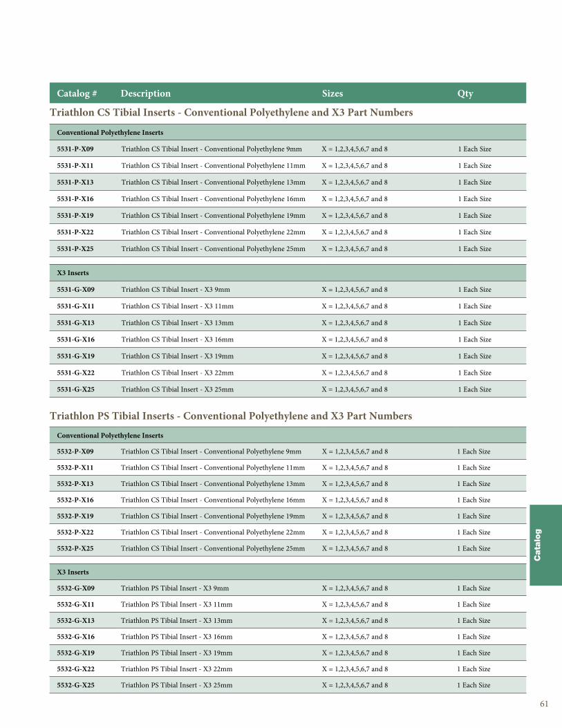
61
Cata
log
Triathlon CS Tibial Inserts - Conventional Polyethylene and X3 Part Numbers
Triathlon PS Tibial Inserts - Conventional Polyethylene and X3 Part Numbers
Catalog # Description Sizes Qty
Conventional Polyethylene Inserts
5531-P-X09 Triathlon CS Tibial Insert - Conventional Polyethylene 9mm X = 1,2,3,4,5,6,7 and 8 1 Each Size
5531-P-X11 Triathlon CS Tibial Insert - Conventional Polyethylene 11mm X = 1,2,3,4,5,6,7 and 8 1 Each Size
5531-P-X13 Triathlon CS Tibial Insert - Conventional Polyethylene 13mm X = 1,2,3,4,5,6,7 and 8 1 Each Size
5531-P-X16 Triathlon CS Tibial Insert - Conventional Polyethylene 16mm X = 1,2,3,4,5,6,7 and 8 1 Each Size
5531-P-X19 Triathlon CS Tibial Insert - Conventional Polyethylene 19mm X = 1,2,3,4,5,6,7 and 8 1 Each Size
5531-P-X22 Triathlon CS Tibial Insert - Conventional Polyethylene 22mm X = 1,2,3,4,5,6,7 and 8 1 Each Size
5531-P-X25 Triathlon CS Tibial Insert - Conventional Polyethylene 25mm X = 1,2,3,4,5,6,7 and 8 1 Each Size
X3 Inserts
5531-G-X09 Triathlon CS Tibial Insert - X3 9mm X = 1,2,3,4,5,6,7 and 8 1 Each Size
5531-G-X11 Triathlon CS Tibial Insert - X3 11mm X = 1,2,3,4,5,6,7 and 8 1 Each Size
5531-G-X13 Triathlon CS Tibial Insert - X3 13mm X = 1,2,3,4,5,6,7 and 8 1 Each Size
5531-G-X16 Triathlon CS Tibial Insert - X3 16mm X = 1,2,3,4,5,6,7 and 8 1 Each Size
5531-G-X19 Triathlon CS Tibial Insert - X3 19mm X = 1,2,3,4,5,6,7 and 8 1 Each Size
5531-G-X22 Triathlon CS Tibial Insert - X3 22mm X = 1,2,3,4,5,6,7 and 8 1 Each Size
5531-G-X25 Triathlon CS Tibial Insert - X3 25mm X = 1,2,3,4,5,6,7 and 8 1 Each Size
Conventional Polyethylene Inserts
5532-P-X09 Triathlon CS Tibial Insert - Conventional Polyethylene 9mm X = 1,2,3,4,5,6,7 and 8 1 Each Size
5532-P-X11 Triathlon CS Tibial Insert - Conventional Polyethylene 11mm X = 1,2,3,4,5,6,7 and 8 1 Each Size
5532-P-X13 Triathlon CS Tibial Insert - Conventional Polyethylene 13mm X = 1,2,3,4,5,6,7 and 8 1 Each Size
5532-P-X16 Triathlon CS Tibial Insert - Conventional Polyethylene 16mm X = 1,2,3,4,5,6,7 and 8 1 Each Size
5532-P-X19 Triathlon CS Tibial Insert - Conventional Polyethylene 19mm X = 1,2,3,4,5,6,7 and 8 1 Each Size
5532-P-X22 Triathlon CS Tibial Insert - Conventional Polyethylene 22mm X = 1,2,3,4,5,6,7 and 8 1 Each Size
5532-P-X25 Triathlon CS Tibial Insert - Conventional Polyethylene 25mm X = 1,2,3,4,5,6,7 and 8 1 Each Size
X3 Inserts
5532-G-X09 Triathlon PS Tibial Insert - X3 9mm X = 1,2,3,4,5,6,7 and 8 1 Each Size
5532-G-X11 Triathlon PS Tibial Insert - X3 11mm X = 1,2,3,4,5,6,7 and 8 1 Each Size
5532-G-X13 Triathlon PS Tibial Insert - X3 13mm X = 1,2,3,4,5,6,7 and 8 1 Each Size
5532-G-X16 Triathlon PS Tibial Insert - X3 16mm X = 1,2,3,4,5,6,7 and 8 1 Each Size
5532-G-X19 Triathlon PS Tibial Insert - X3 19mm X = 1,2,3,4,5,6,7 and 8 1 Each Size
5532-G-X22 Triathlon PS Tibial Insert - X3 22mm X = 1,2,3,4,5,6,7 and 8 1 Each Size
5532-G-X25 Triathlon PS Tibial Insert - X3 25mm X = 1,2,3,4,5,6,7 and 8 1 Each Size
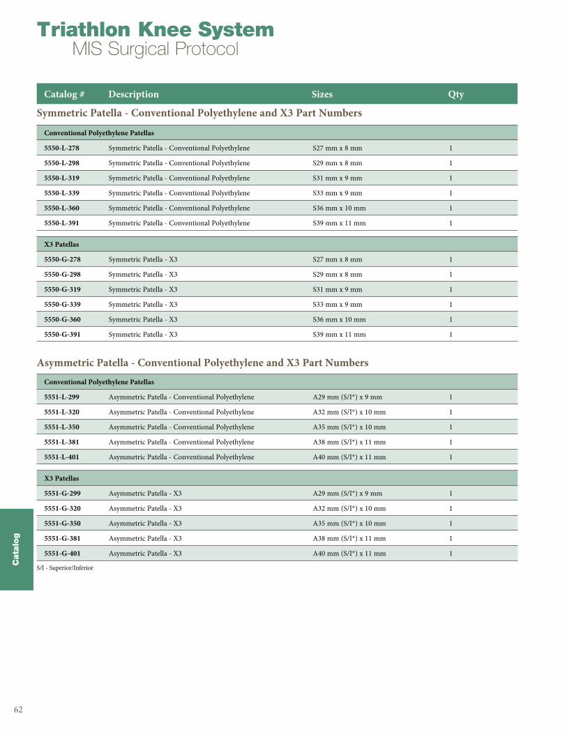
62
Cata
log
Triathlon Knee SystemMIS Surgical Protocol
Symmetric Patella - Conventional Polyethylene and X3 Part Numbers
Asymmetric Patella - Conventional Polyethylene and X3 Part Numbers
Conventional Polyethylene Patellas
5550-L-278 Symmetric Patella - Conventional Polyethylene S27 mm x 8 mm 1
5550-L-298 Symmetric Patella - Conventional Polyethylene S29 mm x 8 mm 1
5550-L-319 Symmetric Patella - Conventional Polyethylene S31 mm x 9 mm 1
5550-L-339 Symmetric Patella - Conventional Polyethylene S33 mm x 9 mm 1
5550-L-360 Symmetric Patella - Conventional Polyethylene S36 mm x 10 mm 1
5550-L-391 Symmetric Patella - Conventional Polyethylene S39 mm x 11 mm 1
X3 Patellas
5550-G-278 Symmetric Patella - X3 S27 mm x 8 mm 1
5550-G-298 Symmetric Patella - X3 S29 mm x 8 mm 1
5550-G-319 Symmetric Patella - X3 S31 mm x 9 mm 1
5550-G-339 Symmetric Patella - X3 S33 mm x 9 mm 1
5550-G-360 Symmetric Patella - X3 S36 mm x 10 mm 1
5550-G-391 Symmetric Patella - X3 S39 mm x 11 mm 1
Catalog # Description Sizes Qty
Conventional Polyethylene Patellas
5551-L-299 Asymmetric Patella - Conventional Polyethylene A29 mm (S/I*) x 9 mm 1
5551-L-320 Asymmetric Patella - Conventional Polyethylene A32 mm (S/I*) x 10 mm 1
5551-L-350 Asymmetric Patella - Conventional Polyethylene A35 mm (S/I*) x 10 mm 1
5551-L-381 Asymmetric Patella - Conventional Polyethylene A38 mm (S/I*) x 11 mm 1
5551-L-401 Asymmetric Patella - Conventional Polyethylene A40 mm (S/I*) x 11 mm 1
X3 Patellas
5551-G-299 Asymmetric Patella - X3 A29 mm (S/I*) x 9 mm 1
5551-G-320 Asymmetric Patella - X3 A32 mm (S/I*) x 10 mm 1
5551-G-350 Asymmetric Patella - X3 A35 mm (S/I*) x 10 mm 1
5551-G-381 Asymmetric Patella - X3 A38 mm (S/I*) x 11 mm 1
5551-G-401 Asymmetric Patella - X3 A40 mm (S/I*) x 11 mm 1
S/I - Superior/Inferior

63
IndicationsGeneral Total Knee Arthroplasty (TKR) Indications include:• Painful, disabling joint disease of the knee resulting
from: non-inflammatory degenerative joint disease (including osteoarthritis, traumatic arthritis or avascular necrosis) or rheumatoid arthritis .
• Post-traumatic loss of knee joint configuration and function .
• Moderate varus, valgus, or flexion deformity in which the ligamentous structures can be returned to adequate function and stability .
• Revision of previous unsuccessful knee replacement or other procedure .
• Fracture of the distal femur and/or proximal tibia that cannot be stabilized by standard fracture management techniques .
Additional Indications for Posterior Stabilized (PS) Components:• Ligamentous instability requiring implant bearing
surface geometries with increased constraint .• Absent or non-functioning posterior cruciate ligament .• Severe anteroposterior instability of the knee joint .
The Triathlon Tritanium Tibial Baseplate and Tritanium Metal-Backed Patella components are indicated for both uncemented and cemented use .
The Triathlon Total Knee System beaded and beaded with Peri-Apatite components are intended for uncemented use only .
Contraindications• Any active or suspected latent infection in or about the
knee joint .• Distant foci of infection which may cause hematogenous
spread to the implant site .• Any mental or neuromuscular disorder which would
create an unacceptable risk of prosthesis instability, prosthesis fixation failure, or complications in post-operative care .
• Bone stock compromised by disease, infection or prior implantation which cannot provide adequate support and/or fixation to the prosthesis .
• Skeletal immaturity .• Severe instability of the knee joint secondary to the
absence of collateral ligament integrity and function .See package insert for warnings, precautions, adverse effects, information for patients and other essential product information .
Before using Triathlon MIS instrumentation, verify:• Instruments have been properly disassembled prior to
cleaning and sterilization;• Instruments have been properly assembled post-
sterilization;• Instruments have maintained design integrity; and,• Proper size configurations are available . For Instructions for Cleaning, Sterilization, Inspection and Maintenance of Orthopaedic Medical Devices, refer to LSTPI-B .

Notes
Triathlon Knee SystemMIS Surgical Protocol
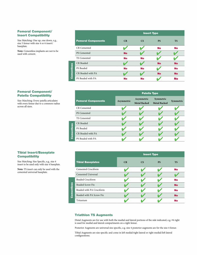
Femoral Component/Insert Compatibility
Size Matching: One up, one down, e .g ., size 5 femur with size 4 or 6 insert/baseplate .
Note: Cementless implants are not to be used with cement .
Femoral Component/Patella Compatibility
Size Matching: Every patella articulates with every femur due to a common radius across all sizes .
Tibial Insert/Baseplate Compatibility Size Matching: Size Specific, e .g ., size 4 insert to be used only with size 4 baseplate .
Note: TS insert can only be used with the cemented universal baseplate .
Insert Type
Femoral Components CR CS PS TS
CR Cemented No No
PS Cemented No
TS Cemented No No
Cem
entl
ess
CR Beaded No No
PS Beaded No No No
CR Beaded with PA No No
PS Beaded with PA No No No
4
4
4
44
4
4
44
4
4
44
Patella Type
Femoral Components AsymmetricAsymmetric
Metal BackedSymmetric
Metal BackedSymmetric
CR Cemented
PS Cemented
TS Cemented
Cem
entl
ess
CR Beaded
PS Beaded
CR Beaded with PA
PS Beaded with PA
4444444
4444444
4444444
4444444
Insert Type
Tibial Baseplates CR CS PS TS
Cemented Cruciform No
Cemented Universal
Cem
entl
ess
Beaded Cruciform No
Beaded Screw Fix No
Beaded with PA Cruciform No
Beaded with PA Screw Fix No
Tritanium No
4444444
4444444
4444444
4
Triathlon TS Augments
Distal Augments are for use with both the medial and lateral portions of the side indicated, e .g . #4 right is used for medial and lateral compartments on a right femur .
Posterior Augments are universal size specific, e .g . size 4 posterior augments are for the size 4 femur .
Tibial Augments are size specific and come in left medial/right lateral or right medial/left lateral configurations .
325 Corporate DriveMahwah, NJ 07430t: 201 831 5000
www .stryker .com
References:1 . Silva M ., Schmalzried TP et al . Knee Strength after Total Knee Arthroplasty . The Journal of Arthroplasty . Vol . 18
(5) 605-11 . 2003 . LIT# LRP100
2 . Bonutti PM et al . Minimally Invasive Total Knee Arthroplasty . JBJS . Vol . 86-A . Suppl 2 26-32 . 2004 . LIT# LRP124
3 . Dalury DF et al . A Comparison of the Mid-vastus and Paramedian Approaches for Total Knee Arthroplasty . Vol . 14 (1) 33-37 . 1999 . LIT# LRP98
4 . Cooper RE et al . Mid-vastus Approach in Total Knee Arthroplasty: A Description and a Cadaveric Study Determining the Distance of the Popliteal Artery From the Patellar Margin of the Incision . The Journal of Arthroplasty . Vol . 14 (4) 505-08 . 1999 . LIT# LRP116
A surgeon must always rely on his or her own professional clinical judgment when deciding whether to use a particular product when treating a particular patient . Stryker does not dispense medical advice and recommends that surgeons be trained in the use of any particular product before using it in surgery .
The information presented is intended to demonstrate the breadth of Stryker product offerings . A surgeon must always refer to the package insert, product label and/or instructions for use before using any Stryker product . The products depicted are CE marked according to the Medical Device Directive 93/42/EEC . Products may not be available in all markets because product availability is subject to the regulatory and/or medical practices in individual markets . Please contact your Stryker representative if you have questions about the availability of Stryker products in your area .
Stryker Corporation or its divisions or other corporate affiliated entities own, use or have applied for the following trademarks or service marks: Stryker, Stryker Orthopaedics, Triathlon, X3 . All other trademarks are trademarks of their respective owners or holders .
TRIATH-SP-5 Rev1 Copyright ©2015 Stryker