
Tree-dimennsional multi-scale plate assembly for maximum ...
29
1 THREE-DIMENSIONAL MULTI-SCALE PLATE ASSEMBLY FOR MAXIMUM HEAT TRANSFER RATE DENSITY T. Bello-Ochende * , J. P. Meyer, J. Dirker Department of Mechanical and Aeronautical Engineering, University of Pretoria, Pretoria, 0002, South Africa. * Corresponding author. Tel.: +27 12 4203105; fax: +27 12 362 5124 E-mail address: [email protected] Abstract This paper extends the design concept for generating multi-scale structures in forced convection for a finite-size flow system to a three-dimensional heat-generating plate with the objectives of maximizing heat transfer rate density, or the heat transfer rate per unit volume. The heat generating plates, arranged in a stack form channels in which the fluids are forced through by an applied pressure difference. The first stage of this work consists of numerical simulation of the flow and heat transfer in a large number of flow configurations, to determine the optimum plate spacing, and the maximum heat transfer rate density. In the subsequent stages, shorter plates are inserted in the centers at adjacent (longer) plates in the entranced region were the boundary layer are thin and there is a core of unused fluid. The heat transfer density is further increased by progressively inserting another set of even shorter plates between the plates and then optimizing the whole structure. The resulting structure is an optimized multi-scale and multi channel structure with horizontal equidistant heated plates of decreasing lengths scales. Further more the effects of plate thickness and dimensionless pressure drop number on the multi-scale structure was investigated. The numerical results are found to be in good agreement with predicted analytical results. Keywords: Constructal theory; Multi-scale; Electronic cooling, Maximum heat transfer rate density; Plate inserts
Transcript of Tree-dimennsional multi-scale plate assembly for maximum ...

1
THREE-DIMENSIONAL MULTI-SCALE PLATE ASSEMBLY FOR MAXIMUM HEAT
TRANSFER RATE DENSITY
T. Bello-Ochende∗, J. P. Meyer, J. Dirker
Department of Mechanical and Aeronautical Engineering, University of Pretoria,
Pretoria, 0002, South Africa.
∗ Corresponding author. Tel.: +27 12 4203105; fax: +27 12 362 5124
E-mail address: [email protected]
Abstract
This paper extends the design concept for generating multi-scale structures in forced
convection for a finite-size flow system to a three-dimensional heat-generating plate with
the objectives of maximizing heat transfer rate density, or the heat transfer rate per unit
volume. The heat generating plates, arranged in a stack form channels in which the fluids
are forced through by an applied pressure difference. The first stage of this work consists of
numerical simulation of the flow and heat transfer in a large number of flow configurations,
to determine the optimum plate spacing, and the maximum heat transfer rate density. In the
subsequent stages, shorter plates are inserted in the centers at adjacent (longer) plates in the
entranced region were the boundary layer are thin and there is a core of unused fluid. The
heat transfer density is further increased by progressively inserting another set of even
shorter plates between the plates and then optimizing the whole structure. The resulting
structure is an optimized multi-scale and multi channel structure with horizontal equidistant
heated plates of decreasing lengths scales. Further more the effects of plate thickness and
dimensionless pressure drop number on the multi-scale structure was investigated. The
numerical results are found to be in good agreement with predicted analytical results.
Keywords: Constructal theory; Multi-scale; Electronic cooling, Maximum heat transfer
rate density; Plate inserts
2
Nomenclature
Be dimensionless pressure number,
d spacing between two-dimensional parallel plates, m
D0 spacing between two plates, m
D1 spacing between the L0 and L1 plates when L1 plate is inserted, m
H stack height, m
j Mesh interation index
k thermal conductivity, W/mK
Lu length of control volume before the plate, m
L0 plate length in the flow direction, m
L1 flow length of the first plate insert, m
L2 Flow length of the second plate insert, m
Ld length of control volume downstream after the plate, m
m number of new inserted plates
n number of plates
P pressure, Pa
Pr Prandtl number
Re Reynold number
q heat transfer, W
q~ dimensionless heat transfer
t plate thickness, m
T temperature, K
Tw wall temperature, K

3
T∞ free-stream temperature, K
u velocity component in the x-direction, m/s
v velocity component, in the y-direction, m/s
w velocity component, in the z-direction, m/s
U∞ free-stream velocity, m/s
W plate width, m
x Cartesian axis direction, m
y Cartesian axis direction, m
z Cartesian axis direction, m
Greek
α thermal diffusivity, m2/s
µ viscosity, kg/s m
ν kinematic viscosity, m2/s
γ convergence criterion
δ boundary layer thickness, m
φ porosity
Subscripts
0, 1, 2 No plate insert, first plate inserts, second plate insert
max maximum
opt optimum
u upstream
w wall
∞ free-stream
4
Superscript
~ dimensionless
1. Introduction
Compactness and miniaturisation are driven by the need to remove more and more heat
transfer from a given volume. The figure of merit is the heat transfer density. A recent
trend in heat transfer research has been the focus on the generation of optimal flow
architecture, as a mechanism by which the system achieves its maximal heat transfer
density objective under certain constraints [1-3]. The strategy is to endow the flow
configuration with the freedom to morph, and to examine systematically many of the
eligible design configurations. Strategy and systematic search mean that architectural
features that have been found to be beneficial in the past can be refined and incorporated
into more complex systems of the present. A similar idea has also been pursued and
implemented by Dirker and co-workers [4-6] in the cooling of power electronics by
embedded solids.
One class of flow features that aid the achievement of high-heat transfer density is the
optimal spacings that have been reported for forced convection [7-9]. The progress in this
area has aso been reported in [10-14]. Optimal spacings have been determined for parallel
plate channels, cylinders in cross-flow, staggered parallel plates, and pin fin arrays with
impinging flow. In each configuration, the optimal spacing is a single-length scale that is
distributed throughout the available volume.
The optimal spacing idea was taken theoretically and numerically one step further in
[1, 7, 15], where the flow structure had not one but several optimal-length scales. These
were distributed non-uniformly through the flow space with more and smaller plates in the

5
entrance region of the available volume. The reason is that the boundary layers were
thinner at the entrance and more plates could be fitted together optimally.
In this paper, we evaluated this design approach numerically, by considering forced
convection cooling of a volume filled by stacks of parallel plates that generate heat. The
plates are modelled three dimensionally which represents the actual geometry in space and
the limitations of the result obtained using two-dimensional parallel plates [1] are
eliminated. The flow and heat transfer are simulated numerically for a wide range of flow
configurations. Each numerical simulation shows that the entrance region of every parallel
plate channel has a core of unused (isothermal) fluid. In this wedge-shaped region, we
progressively inserted smaller heat-generating plates, and then we optimised the multi-scale
assembly. The maximisation of heat transfer density is pursued geometrically, by varying
more and more degrees of freedom. The result is a class of progressively better flow
structures with multiple-length scales that are distributed non-uniformly through the flow
system.
2. Physical model
Consider a stack of three-dimensional heat-generating parallel plates that form a
channel in space as shown in Fig. 1a. The plates are modelled as isothermal with
temperature T = Tw. A stream of coolant with temperature T = T∞ is forced through the
channels that is formed by the plates. The problem consists of maximising the heat transfer
rate between the coolant and the heat-generating plates.
The problem is ruled by the conservation of mass, momentum and energy equations.
They are simplified in accordance with the assumptions of three-dimensional
incompressible steady-state laminar flow with constant properties for a Newtonian fluid.
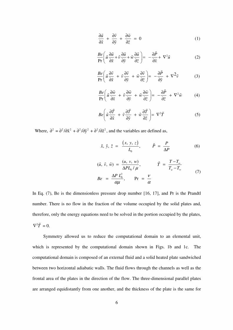
The governing equations in the dimensionless forms are:
6
0 u v w
x y z
∂ ∂ ∂+ + =
∂ ∂ ∂
� � �
� � � (1)
2 Pr
Be u u u Pu v w u
x y z x
∂ ∂ ∂ ∂+ + = − + ∇
∂ ∂ ∂ ∂
�� � �� � � �� � ��
(2)
2 Pr
Be v v v Pu v w v
x y z y
∂ ∂ ∂ ∂+ + = − + ∇
∂ ∂ ∂ ∂
�� � �� � � �� � ��
(3)
2 Pr
Be w w w Pu v w w
x y z z
∂ ∂ ∂ ∂+ + = − + ∇
∂ ∂ ∂ ∂
�� � �� � � �� � � �
(4)
2
T T TBe u v w T
x y z
∂ ∂ ∂+ + = ∇
∂ ∂ ∂
� � ��� � �
� � � (5)
Where, 2 2 2 2 2 2 2 = / x + / y + / z∂ ∂ ∂ ∂ ∂ ∂ ∂� � � , and the variables are defined as,
( )
0
, , , , ,
x y z Px y z P
L P= =
∆�� � � (6)
0
2
0
( , , )( , , ) ,
/
, Pr
w
T Tu v wu v w T
PL T T
P LBe
µ
ν
αµ α
∞
∞
−= =
∆ −
∆= =
�� � �
(7)
In Eq. (7), Be is the dimensionless pressure drop number [16, 17], and Pr is the Prandtl
number. There is no flow in the fraction of the volume occupied by the solid plates and,
therefore, only the energy equations need to be solved in the portion occupied by the plates,
2T∇ � = 0.
Symmetry allowed us to reduce the computational domain to an elemental unit,
which is represented by the computational domain shown in Figs. 1b and 1c. The
computational domain is composed of an external fluid and a solid heated plate sandwiched
between two horizontal adiabatic walls. The fluid flows through the channels as well as the
frontal area of the plates in the direction of the flow. The three-dimensional parallel plates
are arranged equidistantly from one another, and the thickness of the plate is the same for

7
all the plates. To complete the problem formulation, the following boundary conditions are
then specified for the extended three-dimensional computational domain in line with Fig 1b
and 1c:
1, 0, 0 0 P v w and T at x= = = = =� �� � � (8)
0, 0 T
u v w at z and z W z
∂= = = = = =
∂
��� � � � �
� (9)
0 0 0
u wv at y and y D t
y y
∂ ∂= = = = = +
∂ ∂
� �� �� �
� � (10)
0, 1
on the surface of the plates
u v w T= = = =�� � � (11)
0
0
at ( )u d
u v w TP
x x x x
x L L L
∂ ∂ ∂ ∂= = = = =
∂ ∂ ∂ ∂
= + +
�� � ��
� � � �
� � ��
(12)
Additional boundary conditions are zero shear and zero heat flux around the periphery of
the computational domain and no-slip on the plate surfaces in contact with the fluids. In
order to represent the actual flow, an extension was added to the computational domains.
The extent of the computational domains ( uL� and dL� ) was chosen such that the flow in front
and behind the plates (Fig. 1b) behaves like a free stream (i.e. is not affected by the stacks
in regions situated sufficiently far from the stack). The upstream reservoir frees the flow
and allows it to develop hydraulically starting at the entrance plane of the channel, while
the uniform inlet flow boundary condition is specified at the entrance plane of the upstream
reservoir. Doing this eliminates the need to impose a velocity profile at the entrance of the
channels. The downstream reservoir of the computational domain delayed the imposition of
an unrealistic outlet boundary condition on the exit plane of the channel. The symmetry
about y� = 0 and y� = 0 + ,D t� � allows us to perform the calculations in the region defined by

8
Figs. 1b and 1c of the field, namely (0 ≤ y� ≤ 0 + D t� � ). The temperature profile in the
volume occupied by the plates is solved simultaneously with Eqs. (1) - (5) for the fluid
portion of the domain.
The flow and the temperature fields were simulated for several configurations, one
differing slightly from the next, in order to determine the overall heat transfer rate density.
The global objective is to maximize the heat transfer from the plates to the fluid.
0 0
00
0 0 0 0 /2
L LW W
y D y D t
T Tq k dxdz k dxdz
y y= = +
∂ ∂= − +
∂ ∂ ∫ ∫ ∫ ∫
m
i = 1 0 0 0 0 /2 ( /2)
- i i
i i
L LW W
i
y D y D t
T Tn k dxdz k dxdz
y y+ += = +
∂ ∂
∂ ∂ ∑ ∫ ∫ ∫ ∫ (13)
Where (m+1) is the number of length scales. The dimensionless overall heat transfer
density based on the total fluid volume is
0
0
( - )w
qLq
k T T WD∞
=� (14)
Another way of looking at the above optimization objective is to monitor the changes in the
use of plate materials for a plate of finite dimension. The available flow volume is given as
L0 × φH ×W, Both L0, H and W are fixed. The solidity of the assembled stack is 1- φ, where
φ is the porosity of the plate assembly, and φ = (fluid space)/HWL. Therefore, another
indicator of the heat transfer rate density associated with the use of the number of finite
plate materials is given as
(1 )plate material
qq =
−
��
ϕ (15)
Where Eq. (15) can be used as a new performance criterion for multi-scale scale structures.
9
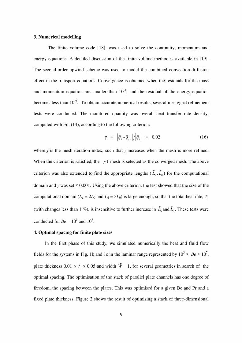
3. Numerical modelling
The finite volume code [18], was used to solve the continuity, momentum and
energy equations. A detailed discussion of the finite volume method is available in [19].
The second-order upwind scheme was used to model the combined convection-diffusion
effect in the transport equations. Convergence is obtained when the residuals for the mass
and momentum equation are smaller than 10-4
, and the residual of the energy equation
becomes less than 10-9
. To obtain accurate numerical results, several mesh/grid refinement
tests were conducted. The monitored quantity was overall heat transfer rate density,
computed with Eq. (14), according to the following criterion:
-1 - 0.02j j jq q qγ = =� � � (16)
where j is the mesh iteration index, such that j increases when the mesh is more refined.
When the criterion is satisfied, the j-1 mesh is selected as the converged mesh. The above
criterion was also extended to find the appropriate lengths ( uL� , dL� ) for the computational
domain and γ was set ≤ 0.001. Using the above criterion, the test showed that the size of the
computational domain (Lu = 2L0 and Ld = 3L0) is large enough, so that the total heat rate, q~
(with changes less than 1 %), is insensitive to further increase in uL� and dL� . These tests were
conducted for Be = 105 and 10
7.
4. Optimal spacing for finite plate sizes
In the first phase of this study, we simulated numerically the heat and fluid flow
fields for the systems in Fig. 1b and 1c in the laminar range represented by 105 ≤ Be ≤ 10
7,
plate thickness 0.01 ≤ t� ≤ 0.05 and width W� = 1, for several geometries in search of the
optimal spacing. The optimisation of the stack of parallel plate channels has one degree of
freedom, the spacing between the plates. This was optimised for a given Be and Pr and a
fixed plate thickness. Figure 2 shows the result of optimising a stack of three-dimensional
10
parallel plate channels cooled with a free stream. Figure 2 also shows that there exists an
optimal spacing of opt 0.18D ≈� with the isothermal plate temperatures.
Figure 3 gives the optimum channel spacing for different Bejan number while
keeping the Prandtl number constant at 0.71. The effect of plate thickness was also
considered. Its show that as the dimensionless pressure difference increases, the optimal
spacing decreases. The effect of plate thickness is negligible in the range considered in this
study. This is due to the fact that the scales of the length and width of the plate are much
greater than the plate thickness.
To further validate our numerical result, we compared our results with the work of
Bejan and Scuibba [9] that investigated the cooling of a stack of parallel plates with an
imposed pressure difference ∆P between x = 0 and x = L0. In that study, the plate-to-plate
channel flow was identical, however the stack being cooled was modelled two-
dimensionally with a channel formed between two adiabatic plates with distance H in
between them (no three-dimensional effect and no free stream around the stack were taken
into consideration). It was further assumed that the plate thickness is negligible, and that the
plate-to-plate spacing, d is small when compared with H, or that the number of plates is
large, thus
1H
nd
= >> (17)
The analysis produced the following optimum spacing for a stack with uniform temperature
on both sides of each plate;
0
-1/4
0 2.7 (Pr = 0.71)LD Be=� (18)
From Fig. 3, the optimal spacing in the log-log graphs of Fig. 3 for t� = 0.01 can be
correlated with the expressions
-0.28
0, 4.51 ( = 0.01, Pr = 0.71)optD Be t=� � (19)
11
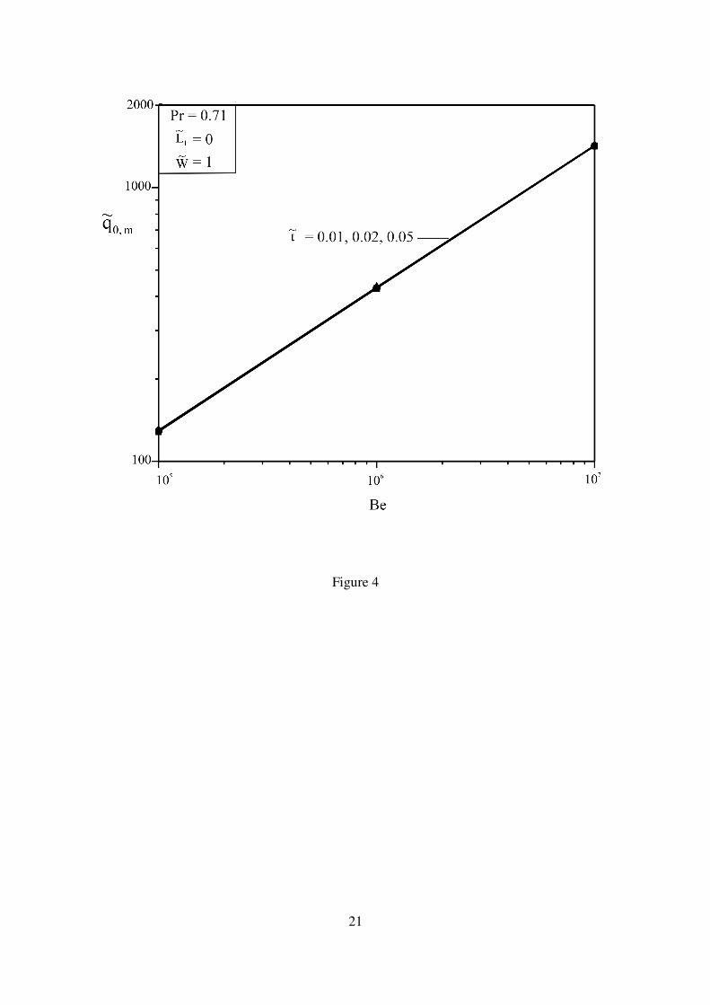
Figure 4 summarises the effect of the dimensionless pressure drop number and plate
thickness on the maximum heat transfer. As the Be number increases, the maximum heat
transfer rate from the plates also increases. The effect of the plate thickness, t� on the heat
transfer rate density is again negligible. The maximum heat transfer rate density in the log-
log graphs of Fig. 4 for t� = 0.01 can be correlated with the expressions
0.52
max 0.31 ( 0.01)q Be t≅ =�� (20)
These results are in agreement with the constructal method [7-8] according to which
the maximum heat transfer means ‘optimal packing’ such that flow regions that do not
contribute to global performance are eliminated. This implies that the packing of Fig. 1 is
achieved when the plates are brought close enough such that their thermal boundary layers
just touch. The thermal boundary layer of a parallel plate with laminar flow and fluid
Prandtl number of order 1 and length L0, has a thickness of order
0
-1/2
0 0.5 ReLL=δ (21)
The behaviour of equations (18, 19, and 21) suggests that the structure of Fig. 1 can be
improved further if we insert shorter plates midway [8] at the entrance of the three-
dimensional plate channels. These possibilities will be discussed in the next section.
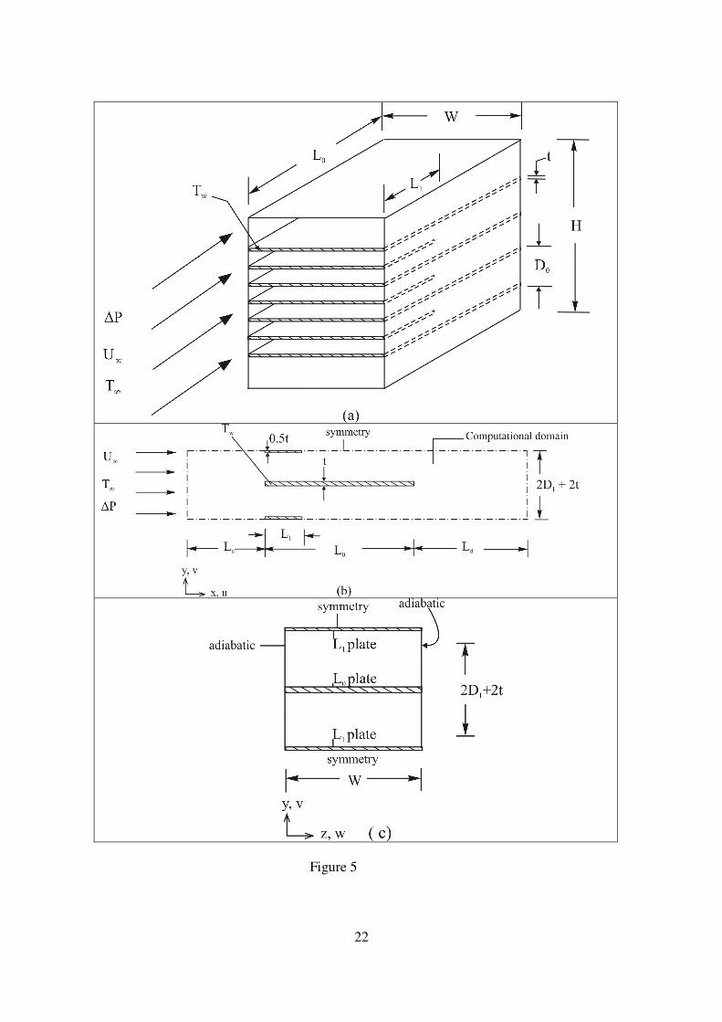
5. Channels with plates insert
In the sequence of increasing more complex structures and utilising the fluid wedge
between two parallel plates, a small 1L� -long plate with plate thickness 0.5t� was inserted
between the plates with thickness t� as shown in Fig. 5. Using the same procedure outlined
above, we numerically solved the governing equations 1-5, subject to the same boundary
conditions.
To determine the contribution of the 1L� -long plate, we fixed 0, optD� at the values
determined previously (Fig. 2) so that the already optimised structure stays the same. The

12
spacing between the plates becomes optD� =
1,opt2 D� . The thickness of the plates was set at t�
= 0.01, as the maximised q� is insensitive to changes in t� as previously determined. We
now optimized 1L� by varying its length until we obtained an optimal length that
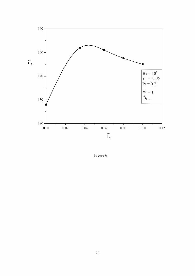
corresponded to the new maximised q� , as is shown in Fig. 6. The procedure stated above
was repeated for several Bejan number in the range 105 ≤ Be ≤ 10
7 and Pr = 0.71, for the
ratio of 0,opt 1,opt/D D� � = 2. Figure 6 shows that the optimum region lies within 1L 0.04≈� .
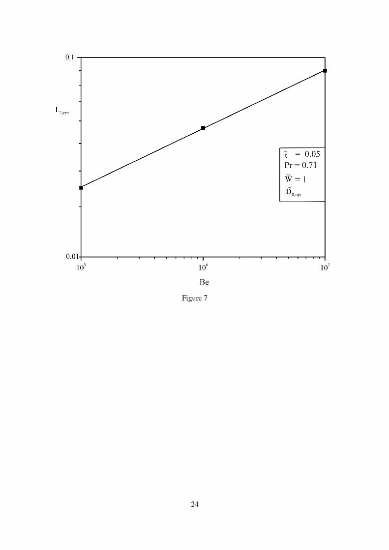
Figure 7, shows the behaviour of the optimal-length scale, 1,optL� . The optimal-length scale
increases as the dimensionless pressure drop number increases. Figure 8 shows the effects
of Bejan number on the maximum heat transfer rate density for the two combinations of
length scales. The maximum heat transfer rate density increases as the number of plates
increases. The results are in agreement with [1], which shows that as the Bejan number
increases the optimal plate insert also increases.
In the sequence of constructing a multi-scale assembly, and determining the
contribution brought about by enduring the flow structure with more degrees of freedom,
we inserted a second plate, 2L� (see Fig. 9) in the channels formed between the L0 and 1,optL�
channel, while still retaining the optimal spacing optD� obtained without plate insert. We
now varied the length of the second plate until an optimal length, 2 opt,L� of the plate that
maximises the heat transfer rate density is obtained. Figure 10 shows that as the pressure
number increases, the plate length increases. This is due to the fact that the slenderness of
the plates also increases with the pressure drop number. Note that optD� =
1,opt2 D� =2,opt4D� .
Figure 11 show the contribution of the second plate inserts to the heat transfer rate density
is not significant. So inserting more plate to the structure is not beneficial to the heat
transfer rate density. It was therefore decided to keep the number of plate inserts to two.
13
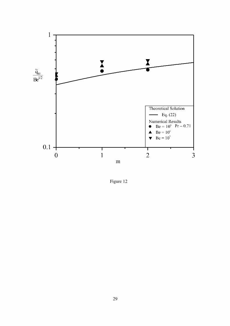
Figure 12 shows the comparisons of the theoretical heat transfer prediction, Eq. (22)
and the results obtained from numerical analysis. It was observed that the general trend is
the same and the agreement is acceptable. Figure 12 shows that the maximised heat transfer
rate density increases in proportion to Be1/2
. This confirms the analytical result [8] which
can be rewritten in the notation employed in this paper for asymmetric plate inserts:
1/2
1/2 0.36 12
mq Be
= +
� (22)
Parameter m is the number of new (inserted) plate lengths, for example when m = 1, 2 as in
Figure 12. The prediction is that the heat transfer rate density increases in progressively
smaller steps as the number of length scales increases. This is confirmed by the numerical
result shown in Fig. 12. Using the relationship obtained from Bejan and Fautrelle [8]
4
32 1
2 10
m m Be + =
(23)
and solving for m for Be in the range 105 to 108, one find that the realistic cut off (smallest)
length scales below which the boundary layer are no longer distinct and where the sequence
of generating optimal length scale ends is approximately m = 2, which also correspond to
our numerical results.
6. Conclusions
In this paper, we illustrated the emergence of a multi-scale forced convection flow
structure for maximal heat transfer rate density for three-dimensional parallel plates
installed in a fixed volume. This objective was achieved by inserting smaller plates in the
entrance region formed between successive plates. This technique utilises to the fullest the
fluid surrounding the two tips of two neighbouring plates where the boundary layers are the
14
thinnest. The optimised spacing was fixed with each new (smaller) plate that is inserted in
the entrance region of each channel.
As the number of plates increases, it is expected that the flow structure becomes less
permeable and the flow rate decreases. At the same time, the total heat transfer density
from the solid structure increases. It was found numerically that when the number of plates
increases to three, the increase in the heat transfer rate density becomes less noticeable
hence for this numerical computation the number of plates inserted in the flow structure
was limited to two.
Optimal spacings were found numerically for structures with one length scale.
Performance increases as complexity increases. The number of plate-length scales is
limited by the validity of the boundary layer assumption. The smallest plate is the one
where the plate length is comparable with the boundary layer thickness.
The fundamental value of this study is that multi-scale flow structures are applicable
to every sector of heat exchanger design. This approach promises the development of new
and unconventional internal flow structures for heat exchangers and cooled electronic
packages.
Acknowledgements
Tunde Bello-Ochende acknowledges the support of the University of Pretoria and the
National Research Foundation of South Africa.
Reference
[1] T. Bello-Ochende, A. Bejan, Maximal heat transfer density: Plates with multiple
lengths in forced convection, Int. J. of Thermal Sciences 43 (2004) 1181 – 1186.
[2] T. Bello-Ochende, L. Liebenberg, J. P. Meyer, Constructal cooling channels for
micro-channel heat sinks, Int. J Heat Mass Transfer 50 (2007) 4141-4150.

15
[3] T. Bello-Ochende, L. Liebenberg, A. G. Malan, A. Bejan, J. P. Meyer, Constructal
conjugate heat transfer in three-dimensional cooling channels, J. Enhanced Heat
Transfer 14 (4) (2007) 279-293.
[4] J. Dirker, W. Liu, J. D. Van Wyk, J. P. Meyer, A. G. Malan, Embedded solid state
heat extraction in integrated power electronic modules, IEEE Transactions on Power
Electronics 20 No. 3 (2005) 694 – 703.
[5] J. Dirker, A. G. Malan, J. P. Meyer, Thermal characterization of rectangular cooling
shapes in heat generating mediums-a three dimensional investigation, Stonjniski
Vesnik – Journal of Mechanical Engineering 51 No 7-8 (2005) 391-398.
[6] J. Dirker, J. D. Van Wyk, J. P. Meyer, Cooling of power electronics by embedded
solids, ASME Journals of Electronic Packaging 128 (2006) 388-387.
[7] A. Bejan, Shape and Structure, from Engineering to Nature, Cambridge University
Press, Cambridge, UK, 2000.
[8] A. Bejan, Y. Fautrelle, Constructal multi-scale structure for maximal heat transfer
density, Acta Mechanica 163 (2003) 39-49.
[9] A. Bejan, E. Sciubba, 1992, The optimal spacing for parallel plates cooled by forced
convection, International Journal of Heat and Mass Transfer 35 (1992) 3259-3264.
[10] T. Aihara, T. Ohara, A. Sasaco, M. Akaku, F. Gori, Augmentation of free-convection
of heat transfer between vertical parallel plates by inserting an auxiliaryplate, 2nd
European Thermal-Sciences and 14th
UIT National Heat Transfer Conference, Rome,
Italy (2006).
[11] S. J. Kim, S. W. Lee, eds., Air cooling technology for electronic equipment, CRC
Press, Boca Raton, FL, 1996, Chapter 1.
[12] J.-M. Koo, S. Im, L. Jiang, K. E. Goodson, Integrated micro channel cooling for
three-dimensional electronic architectures, J. Heat Transfer 127 (2005) 49- 58.
16
[13] R. S. Matos, T. A. Laursen, J. V. C. Vargas, A. Bejan, Three-dimensional
optimization of staggard finned circular and elliptic tubes in forced convection, Int. J.
Thermal Sciences 43 (2004) 447 – 487.
[14] A. M. Morega, A. Bejan, S. W. Lee, Free stream cooling of a stack of parallel plates,
Int. J. Heat and Mass Transfer 38 (1995) 519 – 531.
[15] A. K. da Silva, A. Bejan, Constructal multi-scale structure for maximal heat transfer
density in natural convenction, Int. J. Heat Fluid Flow 26 (2005) 34-44.
[16] S. Bhattacharjee, W. L. Grosshandler, The formation of a wall jet near a high
temperature wall under microgravity environment, ASME HTD 96 (1988) 711-716.
[17] S. Petrescu, Comments on the optimal spacing of parallel plates cooled by forced
convection, Int. J. Heat Mass Transfer 37 (1994) 1283.
[18] www.fluent.com
[19] S. V. Patankar, Numerical Heat Transfer and Fluid flow, Hemisphere, Washington
DC, 1980.
17
Figures Captions
Figure 1 Stack of parallel plate channels and computational domain.
Figure 2 Numerical optimization results for channel spacing.
Figure 3 The optimal spacing for parallel plates with a finite thickness.
Figure 4 The maximised total heat transfer rate from a plate with finite thickness as a
function of dimensionless pressure drop number.
Figure 5 Stacks of parallel plates, with small plate insert.
Figure 6 The effect of the inserted plate with length 1
~L on the dimensionless total heat
transfer density for optopto DD ,1,
~/
~ = 2.
Figure 7 The effect of the pressure drop number on the channel plate spacing with one
plate insert.
Figure 8 The effect of pressure drop number and lengths of the two types of plates on the
dimensionless maximum heat transfer density.
Figure 9 Three-dimensional stacks channels with smaller plate inserts.
Figure 10 The optimized lengths of the flow structure with two length scales for the
ratio optoptopto DDD ,2,1,
~4
~2
~== .
Figure 11 The maximized heat transfer density of the flow structure with three plates.
Figure 12 Comparison between the theoretical maximum heat transfer and the numerical
results obtained from this study versus number of plates inserted.

18
Figure 1

19
Figure 2

20
Figure 3
21
Figure 4
22
Figure 5
23
Figure 6
24
Figure 7

25
Figure 8

26
Figure 9

27
Figure 10

28
Figure 11
29
Figure 12