TRAV&L BUNKER Transfer of Vapour & Liquid System · marine crane technology. ... 3.2.1 Process Flow...
26
TRAV&L BUNKER Transfer of Vapour & Liquid System FEATURES: + SUITABLE FOR SHIP TO SHIP OR SHORE TO SHIP LNG TRANSFER + COMPRISES LIQUID AND VAPOUR RETURN LINES + 14 METRE VERTICAL WORKING ENVELOPE + 16 METRE HORIZONTAL MAXIMUM ACHIEVABLE DISTANCE + 360° SLEW CAPABILITY TRAV&L BUNKER Transfer of Vapour & Liquid System FEATURES: + SUITABLE FOR SHIP TO SHIP OR SHORE TO SHIP LNG TRANSFER + COMPRISES LIQUID AND VAPOUR RETURN LINES + 14 METRE VERTICAL WORKING ENVELOPE + 16 METRE HORIZONTAL MAXIMUM ACHIEVABLE DISTANCE + 360° SLEW CAPABILITY
Transcript of TRAV&L BUNKER Transfer of Vapour & Liquid System · marine crane technology. ... 3.2.1 Process Flow...
TRAV&L BUNKER Transfer of Vapour & Liquid System
FEATURES: + SUITABLE FOR SHIP TO SHIP OR SHORE TO SHIP LNG TRANSFER
+ COMPRISES LIQUID AND VAPOUR RETURN LINES
+ 14 METRE VERTICAL WORKING ENVELOPE
+ 16 METRE HORIZONTAL MAXIMUM ACHIEVABLE DISTANCE
+ 360° SLEW CAPABILITY
TRAV&L BUNKER Transfer of Vapour & Liquid System
FEATURES: + SUITABLE FOR SHIP TO SHIP OR SHORE TO SHIP LNG TRANSFER
+ COMPRISES LIQUID AND VAPOUR RETURN LINES
+ 14 METRE VERTICAL WORKING ENVELOPE
+ 16 METRE HORIZONTAL MAXIMUM ACHIEVABLE DISTANCE
+ 360° SLEW CAPABILITY
CONTENTS
1. DESCRIPTION
2. DIMENSIONS
3. TRAV&L BUNKER SPECIFICATION
3.1 HANDLING SYSTEM
3.2 GAS SYSTEM
3.3 SAFETY SYSTEMS
3.4 ENVIRONMENTAL & TRANSFER CONDITIONS
4. STANDARDS & CODE COMPLIANCE
5. TECHNICAL DESCRIPTION
5.1 HYDRAULIC SYSTEM REQUIREMENTS
5.2 ELECTRIC SYSTEM
5.3 CONTROL SYSTEM
6. OPERATION SEQUENCE
6.1 TRANSFER OPERATIONS
6.2 EMERGENCY SHUTDOWN (ESD)
7. OPTIONS (on request)
7.1 PURGING LINE
7.2 QUICK CONNECT/DISCONNECT (QCDC)
7.3 PENDANT & REMOTE CONTROL
4
10
12
13
16
17
19
21
22
23
23
15
4
14
15
19
22
3
1
This Data Sheet for the TRAV&L Bunker System (patent pending) contains Houlder confi dential and Proprietary Information and is provided for the sole purpose of evaluating the system and should not be transferred, communicated, or otherwise divulged in whole or in part to any third party whether or not such party and third party are bound by secrecy provisions without the express written agreement of Houlder.
Should this data sheet be of further interest and from which future works arise, such works shall be subject to contract including commercial arrangements for the incorporation of any Houlder confi dential and proprietary information into the works. Houlder Document H/016/044/6073 - Rev 3.
[1] Two 8” transfer lines with a liquid fl ow speed of 12 m/s
[2] Datum TRAV&L slew bearing fl ange
[3] Datum TRAV&L pedestal centre line
[4] Non continuous
[5] Feature offered as option
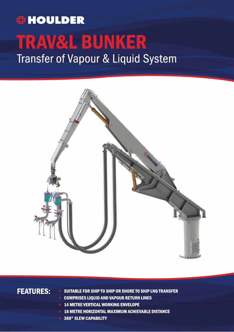
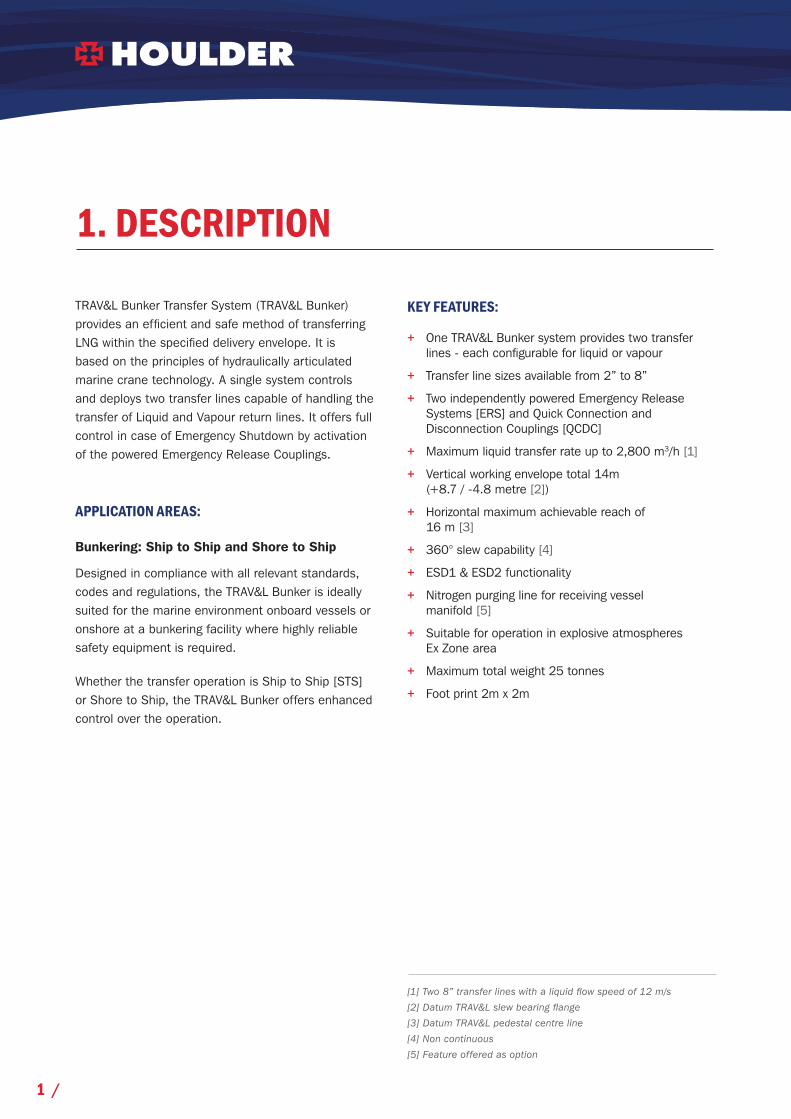
TRAV&L Bunker Transfer System (TRAV&L Bunker) provides an effi cient and safe method of transferring LNG within the specifi ed delivery envelope. It is based on the principles of hydraulically articulated marine crane technology. A single system controls and deploys two transfer lines capable of handling the transfer of Liquid and Vapour return lines. It offers full control in case of Emergency Shutdown by activation of the powered Emergency Release Couplings.
APPLICATION AREAS:
Bunkering: Ship to Ship and Shore to Ship
Designed in compliance with all relevant standards, codes and regulations, the TRAV&L Bunker is ideally suited for the marine environment onboard vessels or onshore at a bunkering facility where highly reliable safety equipment is required.
Whether the transfer operation is Ship to Ship [STS] or Shore to Ship, the TRAV&L Bunker offers enhanced control over the operation.
1. DESCRIPTION
KEY FEATURES:
+ One TRAV&L Bunker system provides two transfer lines - each confi gurable for liquid or vapour
+ Transfer line sizes available from 2” to 8”
+ Two independently powered Emergency Release Systems [ERS] and Quick Connection and Disconnection Couplings [QCDC]
+ Maximum liquid transfer rate up to 2,800 m3/h [1]
+ Vertical working envelope total 14m (+8.7 / -4.8 metre [2])
+ Horizontal maximum achievable reach of 16 m [3]
+ 360° slew capability [4]
+ ESD1 & ESD2 functionality
+ Nitrogen purging line for receiving vessel manifold [5]
+ Suitable for operation in explosive atmospheres Ex Zone area
+ Maximum total weight 25 tonnes
+ Foot print 2m x 2m
1 /

5
6
8
7
12
3
4
9
TRAV&L BUNKERMAIN COMPONENTS:
Constant tension winch
Rotary Hammerhead
ERS valve
QCDC
Transfer Hose
ERS hydraulic supply
Pedestal interface fl ange
Slew Bearing
Transfer line, fl ange interface(Link hoses to be connected with bunker vessel gas system)
Fixed Boom
Centre Boom
Top Boom
NOTE:
Confi guration may vary depending on fi nal installation requirements.
1
2
3
5
8
9
7
6
4
10
11
12
10
11
12
/ 2
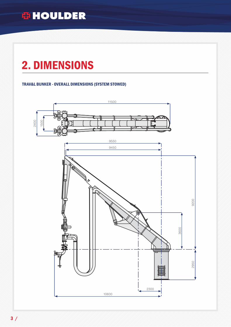
2. DIMENSIONSTRAV&L BUNKER - OVERALL DIMENSIONS (SYSTEM STOWED)
11500
230010600
2400
9200
3600
9450
9550
2950
1500
3 /

3. TRAV&L BUNKER SPECIFICATION
3.1 HANDLING SYSTEM
MECHANICAL AND STRUCTURAL FEATURES:
+ Robust and reliable marine crane design
+ Two hydraulic articulated booms on fi xed interface pedestal
+ Slew angle 360° (120° during transfer operation)
TRAV&L BUNKER – ONBOARD INSTALLATION
CONTROL FEATURES:
+ Fixed operating console or wandering/remote lead control
+ Two speed boom deployment for rapid deployment and fi nal connection
+ Constant tension system also absorbs shock loads
COMPLIANCE:
+ Compliance with Classifi cation Society codes for lifting appliances
+ Suitable for operation in Exclusion Zone (EX Zone) in accordance with IGF Code (Explosive atmospheres)
RELIABILITY FEATURES:
+ Loads on receiving vessel manifolds controlled
+ Fitted with and incorporating industry standard cryogenic equipment
+ Simple installation and interfaces with bunker vessel
+ Maintenance comparable with a standard marine crane
+ Centralised greasing system to reduce necessity for access at height
/ 4

3. TRAV&L BUNKER SPECIFICATION
3.1.1 Working Envelope DiagramsFinal envelopes may differ subject to system installation and location
TRAV&L BUNKER CONNECTION ENVELOPE - SIDE VIEW LOOKING AFT14
m
WORKINGENVELOPE
LIMITS
5m
5 /

-5m
0m
0m 10m-6m
WORKINGENVELOPE
LIMITS
10m
TRAV&L BUNKER CONNECTION ENVELOPE - FRONT VIEW LOOKING OUTBOARD
/ 6
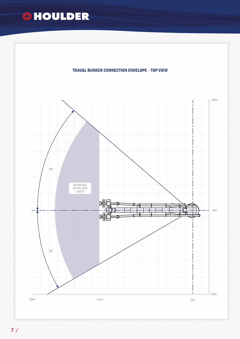
TRAV&L BUNKER CONNECTION ENVELOPE - TOP VIEW
0m
-10m
0m-11m-19m
13m
WORKINGENVELOPE
LIMITS
30̊
40̊
7 /

TRAV&L BUNKER CONNECTION ENVELOPE - VESSEL SCENARIO LOOKING AFT
VESSEL REPRESENTED:
LOA 110mBeam 18mCapacity 5000m3
WORKINGENVELOPE
LIMITS
WORKINGENVELOPE
LIMITS
18m
-16m
0m
0m-18m 18m
/ 8

Z(VERTICAL)
X(TRANSVERSE)
Y(FORE/AFT)
INTERFACE BOLTED FLANGE
Mz
Mx My
3.1.2 Base Load InformationTRAV&L Bunker System Base Load:
TRAV&L BUNKER SYSTEM MAX. TOTAL WEIGHT 25 TONNES
DESCRIPTION DIRECTION VALUEForce x- direction (Fx) 24.6 kNForce y- direction (Fy) 68.1 kNForce z- direction (Fz) 282.2 kNMoment About x- axis (Mx) 534.1 kN.mMoment About y- axis (My) 1875.3 kN.mMoment About z- axis (Mz) 430.8 kN.m
9 /

3.2 GAS SYSTEMNumber of transfer lines .........................................................................................2
Hose diameter available ............................................................................................2”, 3”, 4”, 6”, 8”
Cryogenic equipment design temperature ..................................................-196°C / +50°C
Maximum Allowable Working Pressure ..........................................................10.5 bar g
Maximum allowable liquid fl ow speed ............................................................12m/s
QCDC type ..........................................................................................................................Manually or hydraulically operated
ERS type ................................................................................................................................Double ball valve - hydraulically operated
Interface fl ange type ....................................................................................................ANSI 150lbs Floating SS316 Flange RF
Pipeline and hose fi ttings material ...................................................................Stainless steel 316L
Transfer Hose type .......................................................................................................LNG STS Transfer Hoses
SHOWING ERS ASSEMBLIES AND HYDRAULIC SUPPLY
Houlder work with acknowledged leading equipment suppliers, such as MIB Italiana and Gutteling BV, in supplying the TRAV&L Bunker system.
Electrical isolation between the vessels is ensured through the use of isolation fl anges in the above.
/ 10
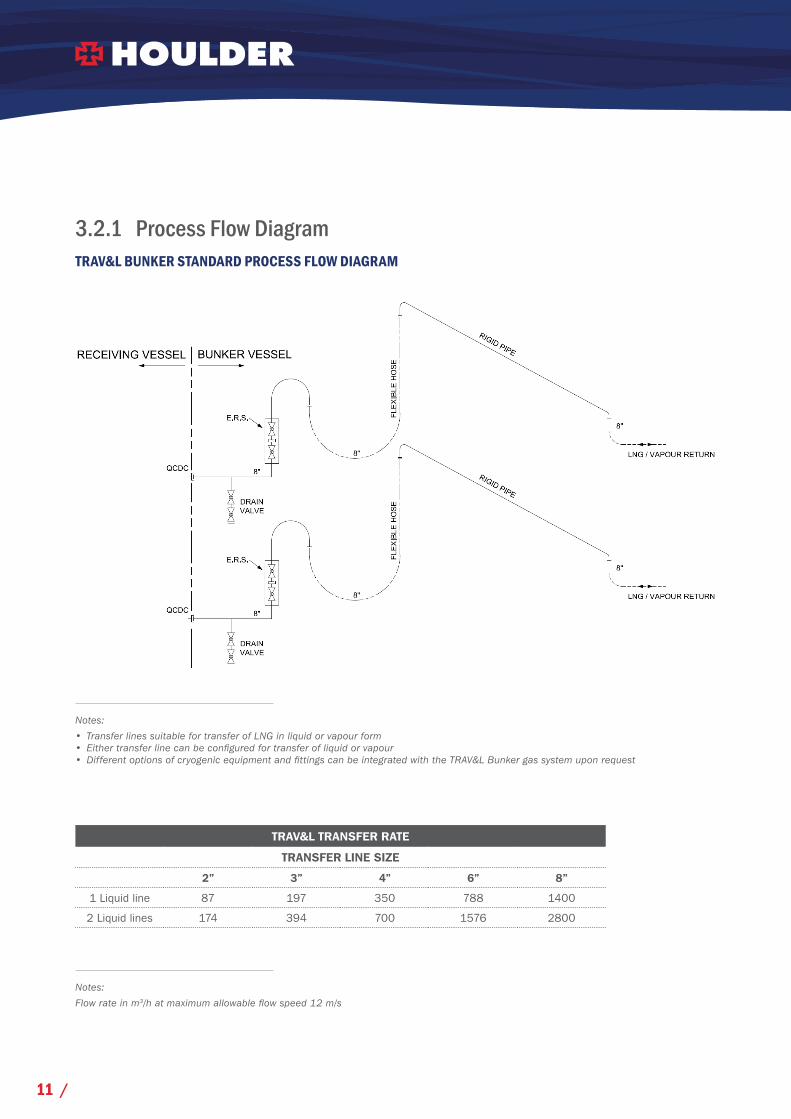
3.2.1 Process Flow DiagramTRAV&L BUNKER STANDARD PROCESS FLOW DIAGRAM
Notes:
• Transfer lines suitable for transfer of LNG in liquid or vapour form• Either transfer line can be confi gured for transfer of liquid or vapour• Different options of cryogenic equipment and fi ttings can be integrated with the TRAV&L Bunker gas system upon request
Notes:
Flow rate in m3/h at maximum allowable fl ow speed 12 m/s
TRAV&L TRANSFER RATE
TRANSFER LINE SIZE
2” 3” 4” 6” 8”
1 Liquid line 87 197 350 788 1400
2 Liquid lines 174 394 700 1576 2800
11 /

3.3 SAFETY
The TRAV&L Bunker system provides ESD functionality during the operation by providing the ability to stop the transfer and disconnect both transfer lines in a safe and controlled way if an ESD event occurs.
The TRAV&L protects the hose from being stretched beyond its maximum length or into unacceptable curvatures. Safety lines initiate the following signals.
• Warning • ESD1 • ESD2
GRAPHICAL REPRESENTATION OF THE ENVELOPE LIMITS
Following the initiation of ESD signals, action will occur as per vessel safety procedure (see section 6.2).
/ 12

3.4 ENVIRONMENTAL & TRANSFER CONDITIONS
TYPE OF TRANSFER:
TRAV&L Bunker system supports side by side STS transfer in sheltered water, harbours and other weather-protected locations. It also supports transfer from a shore facility with the receiving vessel moored alongside.
AMBIENT CONDITIONS:
Minimum Stowed Temperature ............................................ -30°C
Maximum Stowed Temperature ........................................... 45°C
Minimum Operating Temperature ......................................... -20°C
Maximum Operating Temperature ........................................ 40°C
Operational Humidity .......................................................... 0% & 100%
WIND:
Maximum Transfer Windspeed ............................................. 17 m/s
Maximum Stowed Windspeed .............................................. 48 m/s
Maximum Maintenance Windspeed ...................................... 15 m/s
13 /
4. STANDARDS & CODE COMPLIANCE
THE TRAV&L BUNKER GOVERNING STANDARDS AND CODES:
+ ISO “Guidelines for systems and installations for supply of LNG as fuel to ships” (OGP draft 118683)
+ EN 1474: Installation and equipment for liquefi ed natural gas. Design and testing of marine transfer systems.
• Part 1: Design and testing of marine transfer arms
• Part 2: Design and testing of transfer hoses
• Part 3: Offshore transfer systems
+ SIGTTO: LNG Ship to Ship Transfer Guidelines
+ SIGTTO: ESD Arrangements and Linked Ship / Shore Systems for Liquefi ed Gas Carriers
+ SIGTTO: Manifold Recommendations for Liquefi ed Natural Gas Carriers
+ Classifi cation Society Lifting Appliance Rules (BV, LR, DNV as applicable)
+ National and local codes will be applied to TRAV&L Bunker System as required
/ 14

5. TECHNICAL DESCRIPTION
5.1 HYDRAULIC SYSTEM REQUIREMENTS
HYDRAULIC POWER UNIT (HPU):
The HPU provides hydraulic energy for the hydraulic system components used to manoeuvre the booms, motors and miscellaneous accessories, estimated consumption 50 kW.
The HPU consists of a self-contained unit comprising the hydraulic reservoir on which is mounted an electric motor pump system discharging to a pressure manifold block via an inline fi lter.
Mounted on the pressure manifold are the solenoid operated control valves for the associated control functions. The function valves have a manual operation facility to allow manual recovery functions in the event of a controls power supply failure.
Conforming to applicable Exclusion Zone, the unit’s construction enables the HPU to be located in close proximity to the TRAV&L Bunker. Protection from the elements is provided by robust exterior panels.
HYDRAULIC CIRCUIT FEATURES:
+ High and low speed functionality to aid ERS positioning
+ Independent isolating valves are fi tted for each hydraulic cylinder and/ or hydraulic motor
+ Hydraulic locking system for cylinders and motors when the system is shutdown
+ Stainless steel, hydraulic pipelines and fi ttings used throughout
+ Pressure gauges are provided adjacent to the control panel for monitoring both main & ERS system pressures
+ Connection for an optional external hydraulic supply such as an emergency pump
+ Low pressure system circulation pump providing offl ine fi ltration and system pre-heating and/or cooling
A system HPU providing the hydraulic system requirements to operate the TRAV&L Bunker system can be provided by Houlder as a separate costed option.
15 /

5.2 ELECTRICAL SYSTEM + The main control panel enables the operator to control the movement and operation of the TRAV&L Bunker
+ The panel can be located on deck or a ship or the jetty control room adjacent to the TRAV&L Bunker with full visibility of the working envelope
+ The power requirements for the system are 440v supply for the HPU and 24v DC main & emergency supply for the control system
TYPICAL ELECTRICAL POWER LAYOUT FOR ONBOARD INSTALLATION
ELECTRIC CIRCUIT AND EQUIPMENT FEATURES:
+ The local control panel is approved according to applicable Exclusion Zone
+ Equipment and materials are suitable for operation in the marine environment with a minimum IEC 529 protection rating of IP56 or equivalent
+ Isolating switch from main incoming power supply and power ON indication
+ Intrinsically safe circuit cables
+ Flexible cables on the articulated sections are supplied with outer sheath impervious to hydrocarbons and salt water and resistant to U.V. light and corrosion
ELECTRICAL ISOLATION:
Electrical isolation between the vessels is ensured via isolation fl anges located between the fl exible hose and the fi xed structure.
BUNKER VESSEL
TRAV&L BUNKER SYSTEM
HPU
CONTROL PANEL
PENDANT / REMOTE
E STOP
440 V 3Ph - MAIN
24 V - Emergency power supply
Typical electrical power layout for on-board installation
/ 16

5.3 CONTROL SYSTEM
A control panel is provided for each installation to control the functions of the TRAV&L Bunker such as system manoeuvring and ERS sequence.
OPERATOR INTERFACE:
All of the necessary control switches and indicators for operating the complete TRAV&L Bunker system are mounted on the control panel facia. These are grouped to enable the operator to start/stop the HPU, operate the dynamic functions to manoeuver the TRAV&L Bunker, and activate the safety systems.
AVAILABLE OPTIONS:
+ A Human Machine Interface (HMI), in place of the standard control panel, that can be located in the proximity of the TRAV&L Bunker or in the ship control room.
+ Explosion protected pendants or radio remote control units.
17 /

CONTROL PANEL:
The local control panel is compliant for use in Exclusion Zone areas.
CONTROL PANEL TYPICAL FUNCTIONS/INDICATIONS:
Gauges: + System Hydraulic pressure + ERS system pressure
Indicators: + Power ON/OFF + Fault light + Emergency stop
Functions: + Slew: Port / Starboard + Centre boom: Raise/Lower + Top boom: Raise/Lower + Winch: Raise/Lower/Transfer (auto) + Hammer head: Left/Right + ERS: Open (protected), Close, Test
PENDANT/REMOTE TYPICAL FUNCTIONS/INDICATIONS:
Indicators/switches: + Power available + Fault light + Emergency stop
Functions: + Slew: Port/Starboard + Centre Boom: Raise/Lower + Top Boom: Raise/Lower + Emergency Stop + Winch: Raise/Lower/Transfer (auto) + Hammerhead Left/Right + ERS Open / Close
AVAILABLE OPTIONS:
+ Pendant connected to the local control panel with 20 metre extension cable + Radio remote control + Lockable enclosure
/ 18

6. OPERATION SEQUENCE
The following list is a step by step sequence of the typical operations occurring during an LNG transfer
6.1 TRANSFER OPERATIONS
This sequence is provided as a guideline to show the capability of the TRAV&L Bunker system. Final operation guidance shall be developed in accordance with bunker vessel safety procedure and ISO “Guidelines for systems and installations for supply of LNG as fuel to ships” prior to system onboard installation.
+ Connection link hoses between TRAV&L Bunker and vessel gas system to be rigged and confi gured for vapour or liquid transfer in accordance with the receiving vessel manifold arrangement
+ ERSs to be released from stowed position
+ Horizontal distance between QCDC to be adjusted as per receiving vessel manifold arrangement
+ TRAV&L Bunker manoeuvred to its connection position by slewing and raising the articulated booms
(In connection position, the TRAV&L Bunker head is located vertically over the receiving vessel manifold)
+ ERSs lowered to the receiving vessel manifold platform level
+ TRAV&L Bunker is manoeuvred until contact is achieved between the QCDCs and the receiving manifold fl anges
(Operator/s is required on the receiving vessel to ensure that fi nal connection is achieved)
+ QCDCs to be engaged and jack stand legs extended to the deck to secure the connection
+ TRAV&L Bunker control system is now switched to transfer mode with the ERS winch working in tension
+ Transfer operations such as purging, cool-down, draining etc… can now be safely performed as agreed between the vessels
+ QCDCs disengaged now transfer completed
+ ERSs lifted away from receiving vessel manifold platform
+ TRAV&L Bunker manoeuvred back to its stowed position
1
2
3
4
5
6
7
8
9
12
10
11
19 /

BUNKER VESSEL WITH ONBOARD TRAV&L SYSTEM DURING BUNKERING OPERATION
SYSTEM FEATURES:
+ The horizontal span between the two ERSs is adjustable before transfer to ensure obtaining accurate alignment with the receiving fl anges.
+ During the transfer operation, the TRAV&L Bunker automatically compensates for the relative movements between the vessels by its winch operating in tension mode and compensating for vessel movements.
+ Change of loads due to the system release are accommodated by the winch operating in tension mode preventing any shock loads transmitted to the TRAV&L Bunker structure.
+ A Guidance Connection System (GCS) can be provided as an option to facilitate connection operations.
Bunker Vessel:Type: LNG Feeder VesselCapacity: 5,000m3
Length x Beam: 110m x 18m
Receiving Vessel:Type: Tanker
Deadweight: 151,400tLength x Beam: 274m x 46m
/ 20

6.2 EMERGENCY SHUTDOWN ESD
The TRAV&L Bunker safety system interfaces with the bunker vessel or jetty safety system throughout operation to ensure that in the case of emergency shutdown, the transfer is stopped in a controlled and safe way.
TYPICAL ESD COMMUNICATION SYSTEM LAYOUT
TRAV&L TRIGGERS THE FOLLOWING SIGNALS TO THE VESSEL/JETTY SAFETY SYSTEMS:
+ ESD1 signal (In the event that vessel drifts over the ESD1 limits) + ESD2 signal (In the event that vessel drifts over the ESD2 limits)
TRAV&L RECEIVES FROM THE VESSEL/JETTY SAFETY SYSTEM:
+ ESD1 signal (actions initiation) + ESD2 signal (actions initiation)
TRAV&L ACTIONS FOLLOWING ESD1 AND ESD2 SIGNALS:
+ ERS shutdown by closing double ball valve + ERC release by opening the emergency collar + ERS retrieved by winching up the transfer line away from the receiving vessel
(This is an automatic action following the ERC release) + Audio and visual alarm
TRAV&L BUNKER SYSTEM
BUNKER VESSEL SAFETY SYSTEM
RECEIVING VESSEL
ESD 1 VESSEL DRIFT OVER LIMIT
VESSELS SAFETY LINK
ERS SHUTDOWN
ERC RELEASED
ERS RETRIEVETRAV
&L E
SD A
CTI
ON
S
ESD 1 ACTIONS INITIATION
ESD 2 VESSEL DRIFT OVER LIMIT
ESD 2 ACTIONS INITIATION
21 /

7. OPTIONS (on request)
7.1 PURGING LINEA nitrogen purging line can be chosen as an option for the TRAV&L Bunker standard gas system confi guration. Connected to the bunker vessel nitrogen supply this line is linked to the ERS at the end of the hoses providing an effi cient and safe way to purge the receiving vessel manifold during the transfer operation.
This option includes:
+ Nitrogen line from TRAV&L Bunker base to ERSs with isolation valves and quick release connection
+ Vent test point with double isolation valves
+ Pressure gauge or pressure indicator with local and/or remote reading
TRAV&L BUNKER PROCESS FLOW DIAGRAM WITH NITROGEN PURGING LINE (OPTION)
/ 22

7.2 QUICK CONNECT/DISCONNECT COUPLER (QCDC)
The TRAV&L Bunker is provided with a standard manual QCDC; A Hydraulically operated version of the QCDC is available upon request.
QCDC MANUAL AND HYDRAULIC VERSION
7.3 PENDANT & REMOTE CONTROL
Pendant or remote controls can be supplied as an option in addition to the standard fi xed control panel as described in Section 5.3.
Manual QCDC Hydraulic QCDC
Images: MIB Italiana23 /

HOULDER LONDONHoulder LimitedOcean House22 Cousin LaneLondonEC4R 3TEUnited Kingdom
T: +44 (0)20 7283 1220
CONTACTS HOULDER ABERDEENHoulder LimitedSuite E3 NorthpointAberdeen Science & Energy ParkBridge of Don, AberdeenAB23 8HZUnited Kingdom
T: +44 (0)1224 702 200
HOULDER PORTSMOUTHHoulder LimitedNorman HouseKettering TerracePortsmouthPO2 7AEUnited Kingdom
T: +44 (0)23 9287 5277
HOULDER TYNESIDEHoulder Limited22 Witney WayBoldon Business ParkTyne & WearNE35 9PEUnited Kingdom
T: +44 (0)191 536 2777
HOULDER AMERICAS INC5847 San Felipe StreetSuite 1724San Felipe PlazaHoustonTX 77057USA
T: +1 713 561 3808