Traverse Planning with Temporal-Spatial Constraints
9
Traverse Planning with Temporal-Spatial Constraints John L. Bresina * , Paul H. Morris * , Matthew C. Deans * , Tamar E. Cohen + , David S. Lees + * NASA / + SGT, Inc. NASA Ames Research Center, Mail Stop 269-2, Moffett Field, CA 94035 [email protected], [email protected], [email protected], [email protected], [email protected] Abstract We present an approach to planning rover traverses in a domain that includes temporal-spatial constraints. We are using the NASA Resource Prospector mission as a reference mission in our research. The primary objective of this mis- sion is to assess the feasibility of in-situ resource utilization (ISRU) on the lunar surface. One of the mission operations constraints is that the rover is generally required to avoid being in shadow, because it is solar-powered. This require- ment depends on where the rover is located and when it is at that location. Such a temporal-spatial constraint makes trav- erse planning more challenging for both humans and ma- chines. We present a mixed-initiative traverse planner which helps address this challenge. This traverse planner is part of the Exploration Ground Data Systems (xGDS), which we have enhanced with new visualization features, new analysis tools, and new automa- tion for path planning, in order to be applicable to the Re- source Prospector mission. The key concept that is the basis of the analysis tools and that supports the automated path planning is reachability in this dynamic environment due to the temporal-spatial constraints. Introduction We address the problem of mission planning for a robotic mission that includes temporal-spatial constraints. We are investigating this problem within the context of the NASA Resource Prospector (RP) mission. Within this problem domain, there are two important mission requirements that define temporal-spatial constraints on rover operations: (1) avoiding spending time in shadows, because the rover is solar-powered and (2) maintaining direct-to-earth commu- nications with the operations center (unless the rover is idle), because mission operations requires tight interaction with the ground. Both of these constraints depend on where the rover is located and when it is at that location. These dynamic constraints make traverse planning more challenging. We have enhanced an existing traverse plan- ner to address these challenges. The traverse planner is part of the Exploration Ground Data Systems (xGDS), devel- oped at NASA Ames Research Center. We have enhanced the xGDS traverse planner by adding new reachability analyses and automated path planning, and we have devel- oped a variety of new visualizations to present the geo- graphical and temporal data. In the following sections, we first present background on the Resource Prospector mis- sion and xGDS and then describe these new enhancements and how they can be employed to manage domains with temporal-spatial constraints. Resource Prospector Mission Resource Prospector (RP) is a robotic mission currently in formulation by NASA's Advanced Exploration Systems Division within the Human Exploration and Operations Mission Directorate. The mission’s primary objective is to demonstrate the feasibility of in-situ resource utilization (ISRU) on the lunar surface (Andrews, et al., 2014, Colaprete, et al., 2014). In service of this objective, the mission will characterize the distribution of water and oth- er volatiles at the lunar poles, with the goal to map the dis- tribution of surface and subsurface hydrogen-rich materi- als. The areas of interest fall into one of four categories, defined by their thermal character and ice stability depth: • Dry: Temperatures in the top meter expected to be too warm for ice to be stable • Deep: Ice expected to be stable between 50-100 cm of the surface • Shallow: Ice expected to be stable within 50cm of surface • Surface: Ice expected to be stable at the surface; i.e., within a Permanently Shadowed Region, (PSR) The ISRU processing demonstration will use a hydrogen reduction process to extract oxygen from lunar regolith, demonstrating hardware in the lunar environment and cap- turing, quantifying, and displaying water generated from ISRU processing. To keep costs low, the mission will use a solar-powered rover and will use direct-to-earth (DTE) communications to uplink commands and downlink telemetry and science data. Solar power will require landing and traversing in
Transcript of Traverse Planning with Temporal-Spatial Constraints
Traverse Planning with Temporal-Spatial Constraints
John L. Bresina*, Paul H. Morris*, Matthew C. Deans*, Tamar E. Cohen+, David S. Lees+ * NASA / + SGT, Inc.
NASA Ames Research Center, Mail Stop 269-2, Moffett Field, CA 94035 [email protected], [email protected], [email protected], [email protected], [email protected]
Abstract We present an approach to planning rover traverses in a domain that includes temporal-spatial constraints. We are using the NASA Resource Prospector mission as a reference mission in our research. The primary objective of this mis-sion is to assess the feasibility of in-situ resource utilization (ISRU) on the lunar surface. One of the mission operations constraints is that the rover is generally required to avoid being in shadow, because it is solar-powered. This require-ment depends on where the rover is located and when it is at that location. Such a temporal-spatial constraint makes trav-erse planning more challenging for both humans and ma-chines. We present a mixed-initiative traverse planner which helps address this challenge.
This traverse planner is part of the Exploration Ground Data Systems (xGDS), which we have enhanced with new visualization features, new analysis tools, and new automa-tion for path planning, in order to be applicable to the Re-source Prospector mission. The key concept that is the basis of the analysis tools and that supports the automated path planning is reachability in this dynamic environment due to the temporal-spatial constraints.
Introduction We address the problem of mission planning for a robotic mission that includes temporal-spatial constraints. We are investigating this problem within the context of the NASA Resource Prospector (RP) mission. Within this problem domain, there are two important mission requirements that define temporal-spatial constraints on rover operations: (1) avoiding spending time in shadows, because the rover is solar-powered and (2) maintaining direct-to-earth commu-nications with the operations center (unless the rover is idle), because mission operations requires tight interaction with the ground. Both of these constraints depend on where the rover is located and when it is at that location. These dynamic constraints make traverse planning more challenging. We have enhanced an existing traverse plan-ner to address these challenges. The traverse planner is part of the Exploration Ground Data Systems (xGDS), devel-oped at NASA Ames Research Center. We have enhanced the xGDS traverse planner by adding new reachability
analyses and automated path planning, and we have devel-oped a variety of new visualizations to present the geo-graphical and temporal data. In the following sections, we first present background on the Resource Prospector mis-sion and xGDS and then describe these new enhancements and how they can be employed to manage domains with temporal-spatial constraints.
Resource Prospector Mission Resource Prospector (RP) is a robotic mission currently in formulation by NASA's Advanced Exploration Systems Division within the Human Exploration and Operations Mission Directorate. The mission’s primary objective is to demonstrate the feasibility of in-situ resource utilization (ISRU) on the lunar surface (Andrews, et al., 2014, Colaprete, et al., 2014). In service of this objective, the mission will characterize the distribution of water and oth-er volatiles at the lunar poles, with the goal to map the dis-tribution of surface and subsurface hydrogen-rich materi-als. The areas of interest fall into one of four categories, defined by their thermal character and ice stability depth:
• Dry: Temperatures in the top meter expected to be too warm for ice to be stable
• Deep: Ice expected to be stable between 50-100 cm of the surface
• Shallow: Ice expected to be stable within 50cm of surface
• Surface: Ice expected to be stable at the surface; i.e., within a Permanently Shadowed Region, (PSR)
The ISRU processing demonstration will use a hydrogen reduction process to extract oxygen from lunar regolith, demonstrating hardware in the lunar environment and cap-turing, quantifying, and displaying water generated from ISRU processing.
To keep costs low, the mission will use a solar-powered rover and will use direct-to-earth (DTE) communications to uplink commands and downlink telemetry and science data. Solar power will require landing and traversing in
sunlit areas to maintain power levels, and periodically op-erating on battery power to collect measurements of vola-tiles in permanently shadowed regions. DTE communica-tions are required because there are no plans for a concur-rent orbital mission and adding an orbiting communication relay is cost prohibitive. Staying in sunlight and in line-of-site of the Earth are temporal-spatial constraints. A third operations constraint is that the rover must avoid slopes that are over fifteen degrees. This is a spatial constraint, with no temporal aspect.
Mission planning for RP involves constructing a tour from a lunar landing site and landing time to a number of sites, or stations, at which activities are performed (e.g., payload operations), such that the rover is kept safe and the mission objectives are met.
A landing ellipse is considered safe if it satisfies the slope constraint and satisfies the sunlight and comm con-straints with a temporal margin of forty-eight hours; that is, the two constraints are satisfied at the time of landing and remain satisfied throughout the next forty-eight hours. A station is considered safe if its location satisfies the slope constraint and from the arrival time until the departure time (i.e., throughout the station dwell time), the location satis-fies the sunlight and comm constraints. A traverse between two stations is considered safe if each location on the path satisfies the slope constraint and satisfies the sunlight and comm constraints at the time the rover is expected to be at that location.
xGDS Overview The Exploration Ground Data Systems (xGDS), synthesiz-es real world data from sensors, robots, ROVs, mobile de-
vices, etc., and from human observations into rich, digital maps and displays for planning, analysis, and decision making. xGDS is a highly collaborative, interactive suite of web software. xGDS has been employed in rover field tests and analog missions, e.g., the Mojave Volatiles Prospec-tor, MVP (Heldmann, et al., 2016).
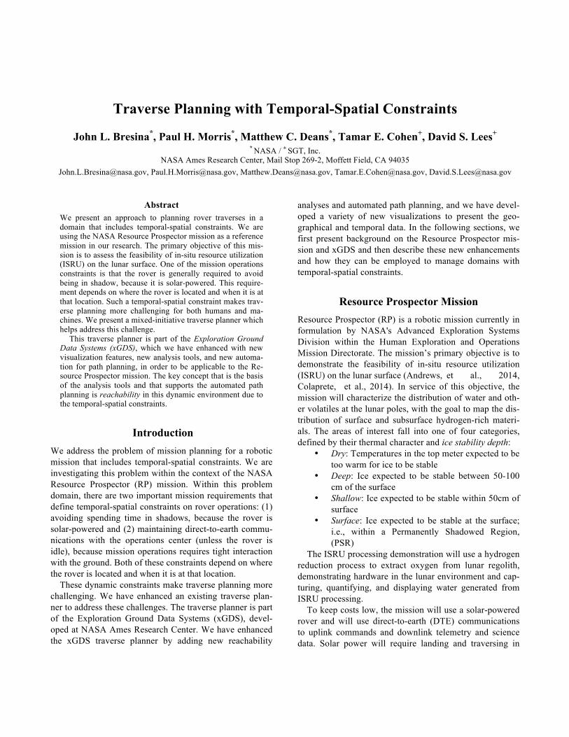
The map server is a repository for organizing multiple layers of map data. xGDS users can manage a tree of map layers, including simple markup, kml imports, and com-plex tiled geoTIFF data layers. Figure 1 shows an image of the map server displaying slope data for an area of the lunar north pole.
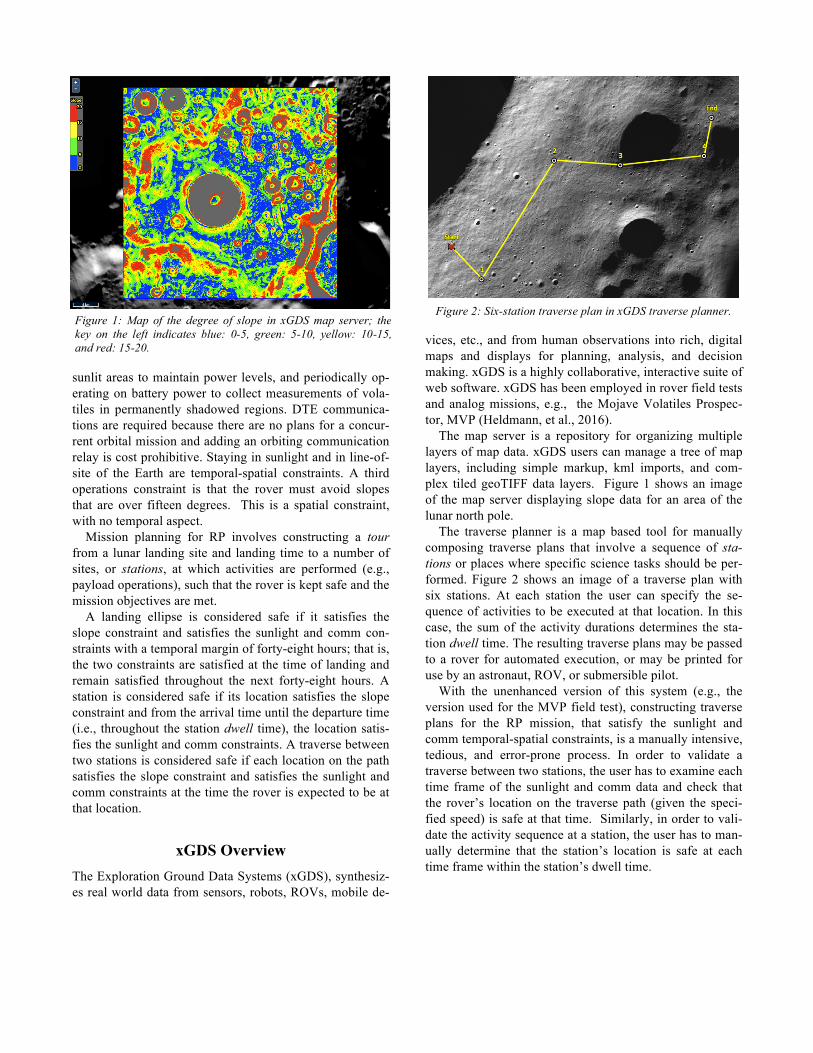
The traverse planner is a map based tool for manually composing traverse plans that involve a sequence of sta-tions or places where specific science tasks should be per-formed. Figure 2 shows an image of a traverse plan with six stations. At each station the user can specify the se-quence of activities to be executed at that location. In this case, the sum of the activity durations determines the sta-tion dwell time. The resulting traverse plans may be passed to a rover for automated execution, or may be printed for use by an astronaut, ROV, or submersible pilot.
With the unenhanced version of this system (e.g., the version used for the MVP field test), constructing traverse plans for the RP mission, that satisfy the sunlight and comm temporal-spatial constraints, is a manually intensive, tedious, and error-prone process. In order to validate a traverse between two stations, the user has to examine each time frame of the sunlight and comm data and check that the rover’s location on the traverse path (given the speci-fied speed) is safe at that time. Similarly, in order to vali-date the activity sequence at a station, the user has to man-ually determine that the station’s location is safe at each time frame within the station’s dwell time.
Figure 1: Map of the degree of slope in xGDS map server; the key on the left indicates blue: 0-5, green: 5-10, yellow: 10-15, and red: 15-20.
Figure 2: Six-station traverse plan in xGDS traverse planner.
In the following sections we describe the key capabili-ties we have added to xGDS to make the planning process easier and safer via new visualization capabilities and new automation in terms of reachability analyses and path gen-eration. The new automation capabilities reduces the bur-den on the user and makes the xGDS traverse planner an effective mixed-initiative system.
Visualization Enhancements For this project, we have adapted xGDS’ map server and traverse planner to meet the needs of the RP mission. For planning lunar traverses, we have configured the map serv-er to render lunar maps in polar stereographic projection, using base map data synthesized at Arizona State Universi-ty from LROC imagery (http://lroc.sese.asu.edu/).
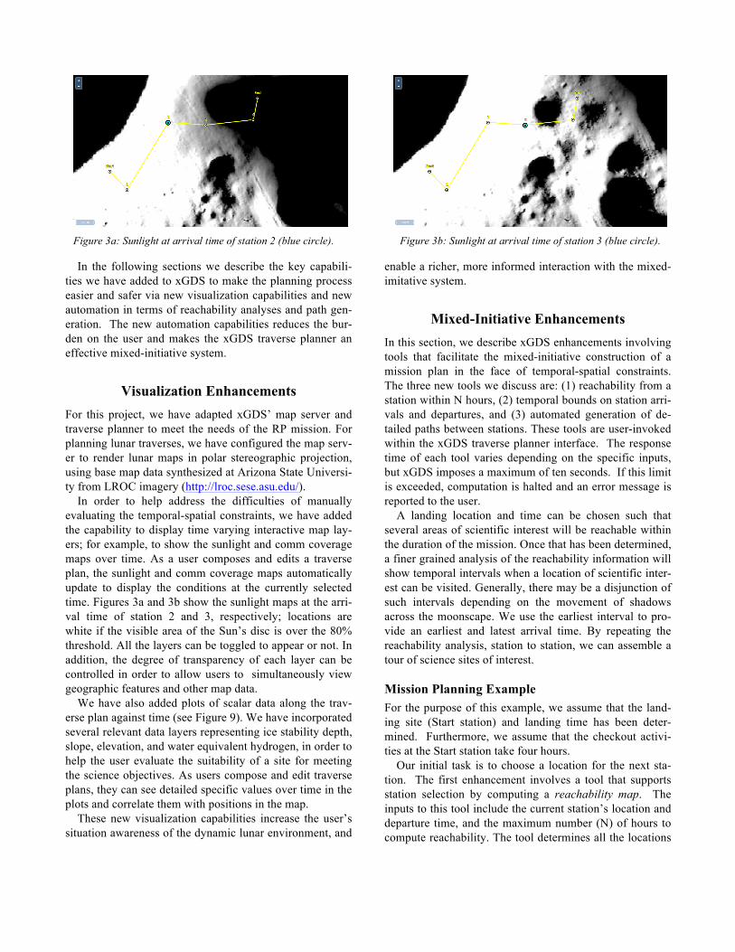
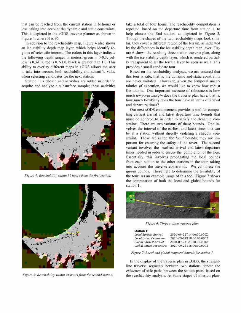
In order to help address the difficulties of manually evaluating the temporal-spatial constraints, we have added the capability to display time varying interactive map lay-ers; for example, to show the sunlight and comm coverage maps over time. As a user composes and edits a traverse plan, the sunlight and comm coverage maps automatically update to display the conditions at the currently selected time. Figures 3a and 3b show the sunlight maps at the arri-val time of station 2 and 3, respectively; locations are white if the visible area of the Sun’s disc is over the 80% threshold. All the layers can be toggled to appear or not. In addition, the degree of transparency of each layer can be controlled in order to allow users to simultaneously view geographic features and other map data.
We have also added plots of scalar data along the trav-erse plan against time (see Figure 9). We have incorporated several relevant data layers representing ice stability depth, slope, elevation, and water equivalent hydrogen, in order to help the user evaluate the suitability of a site for meeting the science objectives. As users compose and edit traverse plans, they can see detailed specific values over time in the plots and correlate them with positions in the map.
These new visualization capabilities increase the user’s situation awareness of the dynamic lunar environment, and
enable a richer, more informed interaction with the mixed-imitative system.
Mixed-Initiative Enhancements In this section, we describe xGDS enhancements involving tools that facilitate the mixed-initiative construction of a mission plan in the face of temporal-spatial constraints. The three new tools we discuss are: (1) reachability from a station within N hours, (2) temporal bounds on station arri-vals and departures, and (3) automated generation of de-tailed paths between stations. These tools are user-invoked within the xGDS traverse planner interface. The response time of each tool varies depending on the specific inputs, but xGDS imposes a maximum of ten seconds. If this limit is exceeded, computation is halted and an error message is reported to the user.
A landing location and time can be chosen such that several areas of scientific interest will be reachable within the duration of the mission. Once that has been determined, a finer grained analysis of the reachability information will show temporal intervals when a location of scientific inter-est can be visited. Generally, there may be a disjunction of such intervals depending on the movement of shadows across the moonscape. We use the earliest interval to pro-vide an earliest and latest arrival time. By repeating the reachability analysis, station to station, we can assemble a tour of science sites of interest.
Mission Planning Example For the purpose of this example, we assume that the land-ing site (Start station) and landing time has been deter-mined. Furthermore, we assume that the checkout activi-ties at the Start station take four hours. Our initial task is to choose a location for the next sta-tion. The first enhancement involves a tool that supports station selection by computing a reachability map. The inputs to this tool include the current station’s location and departure time, and the maximum number (N) of hours to compute reachability. The tool determines all the locations
Figure 3a: Sunlight at arrival time of station 2 (blue circle). Figure 3b: Sunlight at arrival time of station 3 (blue circle).
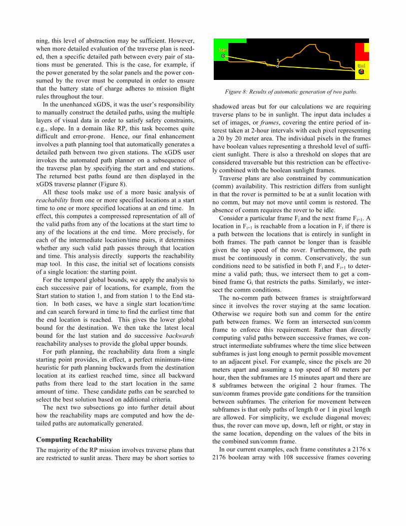
that can be reached from the current station in N hours or less, taking into account the dynamic and static constraints. This is depicted in the xGDS traverse planner as shown in Figure 4, where N is 96.
In addition to the reachability map, Figure 4 also shows an ice stability depth map layer, which helps identify re-gions of scientific interest. The colors in this layer indicate the following depth ranges in meters: green is 0-0.3, yel-low is 0.3-0.7, red is 0.7-1.0, black is greater than 1.0. This ability to overlay different maps in xGDS allows the user to take into account both reachability and scientific value when selecting candidates for the next station. Station 1 is chosen and activities are added in order to acquire and analyze a subsurface sample; these activities
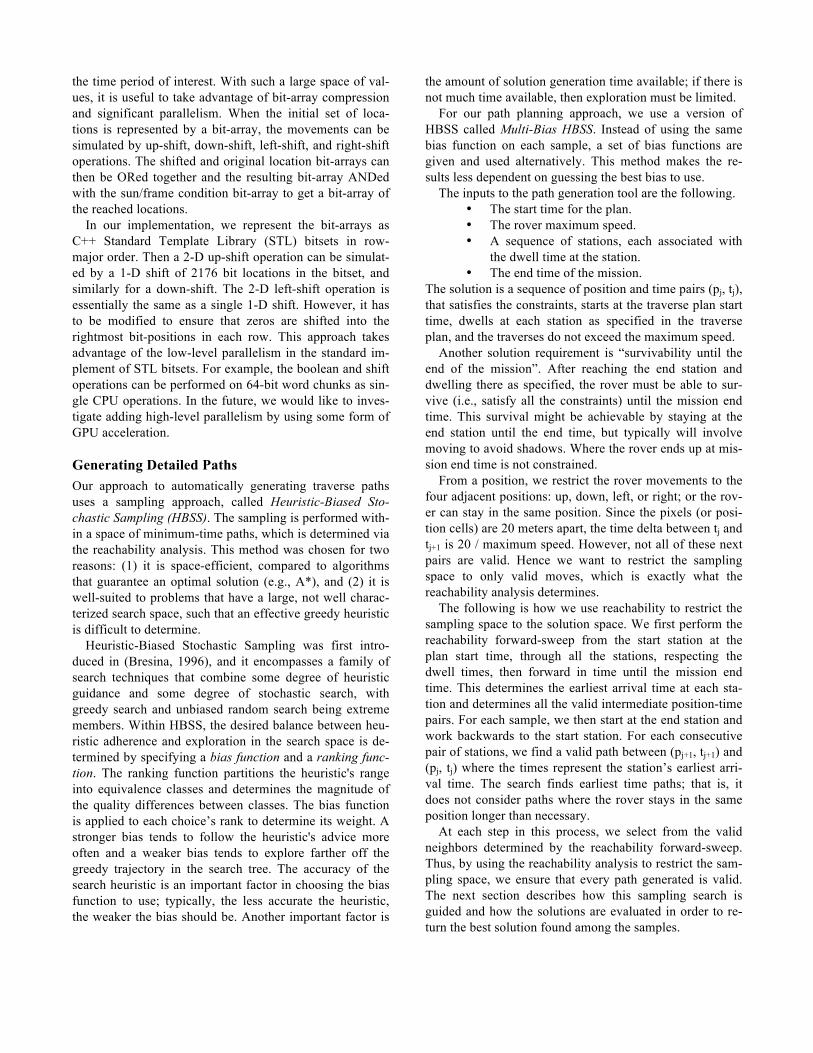
take a total of four hours. The reachability computation is repeated, based on the departure time from station 1, to help choose the End station, as depicted in Figure 5. Though the shapes of the two reachability maps look simi-lar, they cover a different region of the terrain, as indicated by the differences in the ice stability depth map layer. Fig-ure 6 shows the resulting three-station traverse plan, along with the ice stability depth layer, which is rendered partial-ly transparent to let the terrain layer be seen as well. This provides a small candidate tour.
Based on the reachability analyses, we are ensured that this tour is safe; that is, the dynamic and static constraints are never violated. However, given the temporal uncer-tainties of execution, we would like to know how robust the tour is. One important measure of robustness is how much temporal margin does the traverse plan have, that is, how much flexibility does the tour have in terms of arrival and departure times?
Our next xGDS enhancement provides a tool for compu-ting earliest arrival and latest departure time bounds that must be adhered to in order to satisfy the dynamic con-straints. There are two variants of these bounds. One in-volves the interval of the earliest and latest times one can be at a station without directly violating a shadow con-straint. These are called the local bounds; they are im-portant for ensuring the safety of the rover. The second variant involves the earliest arrival and latest departure times needed in order to ensure the completion of the tour. Essentially, this involves propagating the local bounds from each station to the other stations in the tour, taking into account the traverse constraints. We call these the global bounds. These help to determine the feasibility of the tour. As an example usage of this tool, Figure 7 shows the computation of both the local and global bounds for station 1.
In the display of the traverse plan in xGDS, the straight-line traverse segments between two stations denote the existence of safe paths between the station pairs, based on the reachability analysis. At some stages of mission plan-
Figure 4: Reachability within 96 hours from the first station.
Figure 5: Reachability within 96 hours from the second station.
Station1: LocalEarliestArrival:2020-09-22T14:00:00.000Z LocalLatestDeparture:2020-09-24T18:00:00.000Z GlobalEarliestArrival:2020-09-23T20:00:00.000Z GlobalLatestDeparture:2020-09-24T16:00:00.000Z
Figure 7: Local and global temporal bounds for station 1.
Figure 6: Three station traverse plan.
ning, this level of abstraction may be sufficient. However, when more detailed evaluation of the traverse plan is need-ed, then a specific detailed path between every pair of sta-tions must be generated. This is the case, for example, if the power generated by the solar panels and the power con-sumed by the rover must be computed in order to ensure that the battery state of charge adheres to mission flight rules throughout the tour.
In the unenhanced xGDS, it was the user’s responsibility to manually construct the detailed paths, using the multiple layers of visual data in order to satisfy safety constraints, e.g., slope. In a domain like RP, this task becomes quite difficult and error-prone. Hence, our final enhancement involves a path planning tool that automatically generates a detailed path between two given stations. The xGDS user invokes the automated path planner on a subsequence of the traverse plan by specifying the start and end stations. The returned best paths found are then displayed in the xGDS traverse planner (Figure 8).
All these tools make use of a more basic analysis of reachability from one or more specified locations at a start time to one or more specified locations at an end time. In effect, this computes a compressed representation of all of the valid paths from any of the locations at the start time to any of the locations at the end time. More precisely, for each of the intermediate location/time pairs, it determines whether any such valid path passes through that location and time. This analysis directly supports the reachability map tool. In this case, the initial set of locations consists of a single location: the starting point. For the temporal global bounds, we apply the analysis to each successive pair of locations, for example, from the Start station to station 1, and from station 1 to the End sta-tion. In both cases, we have a single start location/time and can search forward in time to find the earliest time that the end location is reached. This gives the lower global bound for the destination. We then take the latest local bound for the last station and do successive backwards reachability analyses to provide the global upper bounds. For path planning, the reachability data from a single starting point provides, in effect, a perfect minimum-time heuristic for path planning backwards from the destination location at its earliest reached time, since all backward paths from there lead to the start location in the same amount of time. These candidate paths can be searched to select the best solution based on additional criteria.
The next two subsections go into further detail about how the reachability maps are computed and how the de-tailed paths are automatically generated.
Computing Reachability The majority of the RP mission involves traverse plans that are restricted to sunlit areas. There may be short sorties to
shadowed areas but for our calculations we are requiring traverse plans to be in sunlight. The input data includes a set of images, or frames, covering the entire period of in-terest taken at 2-hour intervals with each pixel representing a 20 by 20 meter area. The individual pixels in the frames have boolean values representing a threshold level of suffi-cient sunlight. There is also a threshold on slopes that are considered traversable but this restriction can be effective-ly combined with the boolean sunlight frames. Traverse plans are also constrained by communication (comm) availability. This restriction differs from sunlight in that the rover is permitted to be at a sunlit location with no comm, but may not move until comm is restored. The absence of comm requires the rover to be idle.
Consider a particular frame Fi and the next frame Fi+1. A location in Fi+1 is reachable from a location in Fi if there is a path between the locations that is entirely in sunlight in both frames. The path cannot be longer than is feasible given the top speed of the rover. Furthermore, the path must be continuously in comm. Conservatively, the sun conditions need to be satisfied in both Fi and Fi+1 to deter-mine a valid path; thus, we intersect them to get a com-bined frame Gi that restricts the paths. Similarly, we inter-sect the comm conditions. The no-comm path between frames is straightforward since it involves the rover staying at the same location. Otherwise we require both sun and comm for the entire path between frames. We form an intersected sun/comm frame to enforce this requirement. Rather than directly computing valid paths between successive frames, we con-struct intermediate subframes where the time slice between subframes is just long enough to permit possible movement to an adjacent pixel. For example, since the pixels are 20 meters apart and assuming a top speed of 80 meters per hour, then the subframes are 15 minutes apart and there are 8 subframes between the original 2 hour frames. The sun/comm frames provide gate conditions for the transition between subframes. The criterion for movement between subframes is that only paths of length 0 or 1 in pixel length are allowed. For simplicity, we exclude diagonal moves; thus, the rover can move up, down, left or right, or stay in the same location, depending on the values of the bits in the combined sun/comm frame.
In our current examples, each frame constitutes a 2176 x 2176 boolean array with 108 successive frames covering
Figure 8: Results of automatic generation of two paths.
the time period of interest. With such a large space of val-ues, it is useful to take advantage of bit-array compression and significant parallelism. When the initial set of loca-tions is represented by a bit-array, the movements can be simulated by up-shift, down-shift, left-shift, and right-shift operations. The shifted and original location bit-arrays can then be ORed together and the resulting bit-array ANDed with the sun/frame condition bit-array to get a bit-array of the reached locations. In our implementation, we represent the bit-arrays as C++ Standard Template Library (STL) bitsets in row-major order. Then a 2-D up-shift operation can be simulat-ed by a 1-D shift of 2176 bit locations in the bitset, and similarly for a down-shift. The 2-D left-shift operation is essentially the same as a single 1-D shift. However, it has to be modified to ensure that zeros are shifted into the rightmost bit-positions in each row. This approach takes advantage of the low-level parallelism in the standard im-plement of STL bitsets. For example, the boolean and shift operations can be performed on 64-bit word chunks as sin-gle CPU operations. In the future, we would like to inves-tigate adding high-level parallelism by using some form of GPU acceleration.
Generating Detailed Paths Our approach to automatically generating traverse paths uses a sampling approach, called Heuristic-Biased Sto-chastic Sampling (HBSS). The sampling is performed with-in a space of minimum-time paths, which is determined via the reachability analysis. This method was chosen for two reasons: (1) it is space-efficient, compared to algorithms that guarantee an optimal solution (e.g., A*), and (2) it is well-suited to problems that have a large, not well charac-terized search space, such that an effective greedy heuristic is difficult to determine.
Heuristic-Biased Stochastic Sampling was first intro-duced in (Bresina, 1996), and it encompasses a family of search techniques that combine some degree of heuristic guidance and some degree of stochastic search, with greedy search and unbiased random search being extreme members. Within HBSS, the desired balance between heu-ristic adherence and exploration in the search space is de-termined by specifying a bias function and a ranking func-tion. The ranking function partitions the heuristic's range into equivalence classes and determines the magnitude of the quality differences between classes. The bias function is applied to each choice’s rank to determine its weight. A stronger bias tends to follow the heuristic's advice more often and a weaker bias tends to explore farther off the greedy trajectory in the search tree. The accuracy of the search heuristic is an important factor in choosing the bias function to use; typically, the less accurate the heuristic, the weaker the bias should be. Another important factor is
the amount of solution generation time available; if there is not much time available, then exploration must be limited.
For our path planning approach, we use a version of HBSS called Multi-Bias HBSS. Instead of using the same bias function on each sample, a set of bias functions are given and used alternatively. This method makes the re-sults less dependent on guessing the best bias to use.
The inputs to the path generation tool are the following. • The start time for the plan. • The rover maximum speed. • A sequence of stations, each associated with
the dwell time at the station. • The end time of the mission.
The solution is a sequence of position and time pairs (pj, tj), that satisfies the constraints, starts at the traverse plan start time, dwells at each station as specified in the traverse plan, and the traverses do not exceed the maximum speed.
Another solution requirement is “survivability until the end of the mission”. After reaching the end station and dwelling there as specified, the rover must be able to sur-vive (i.e., satisfy all the constraints) until the mission end time. This survival might be achievable by staying at the end station until the end time, but typically will involve moving to avoid shadows. Where the rover ends up at mis-sion end time is not constrained.
From a position, we restrict the rover movements to the four adjacent positions: up, down, left, or right; or the rov-er can stay in the same position. Since the pixels (or posi-tion cells) are 20 meters apart, the time delta between tj and tj+1 is 20 / maximum speed. However, not all of these next pairs are valid. Hence we want to restrict the sampling space to only valid moves, which is exactly what the reachability analysis determines.
The following is how we use reachability to restrict the sampling space to the solution space. We first perform the reachability forward-sweep from the start station at the plan start time, through all the stations, respecting the dwell times, then forward in time until the mission end time. This determines the earliest arrival time at each sta-tion and determines all the valid intermediate position-time pairs. For each sample, we then start at the end station and work backwards to the start station. For each consecutive pair of stations, we find a valid path between (pj+1, tj+1) and (pj, tj) where the times represent the station’s earliest arri-val time. The search finds earliest time paths; that is, it does not consider paths where the rover stays in the same position longer than necessary.
At each step in this process, we select from the valid neighbors determined by the reachability forward-sweep. Thus, by using the reachability analysis to restrict the sam-pling space, we ensure that every path generated is valid. The next section describes how this sampling search is guided and how the solutions are evaluated in order to re-turn the best solution found among the samples.
In order to instantiate HBSS for a specific problem do-main, we define the following: a heuristic function, a rank-ing function, a bias function (or multiple bias functions in this case), and a solution evaluation method. Our path planning heuristic is Manhattan distance. The ranking function groups choices in the same equivalence class only if they have the same heuristic score, where better score means lower rank. As mentioned, we use multiple bias functions; they are all polynomial functions, of the rank, with exponents of -1 through -10.
Our solution evaluation method uses two criteria. The primary criterion is the minimal distance travelled, based on the sum of the Manhattan distance between all consecu-tive pairs of position-times. The secondary criterion is based on temporal margin within the reachability space. The temporal margin at a position-time is how much long-er the rover can stay at that position and still be able to survive until the mission end time. The metric we are using is the minimum of the margin over all position-time pairs in the path, where the largest minimum margin is pre-ferred. This secondary criterion is only used to break ties with respect to the distance criterion. To generate each of the two paths in Figure 8, 1, 000 samples were used.
Concluding Remarks In this section, we mention some related work, describe future directions we are pursuing, and conclude.
Related Work An early system that integrated activity planning, resource management, and traverse planning is TEMPEST (Tomp-kins, Stentz, Wettergreen, 2004). The system employed the Incremental Search Engine (ISE), which is a graph-theory based, heuristic search algorithm that supports planning in high-dimensional spaces.
There is other ongoing work based on the RP problem domain; see, for example, (Cunningham, et al., 2014). To cope with the large search space, they perform a temporal compression of the dynamic terrain data and use an hierar-chical planning approach. A low-resolution planner com-putes feasible paths based on pre-computed results from a high-resolution planner. The search is carried out by an A* approach. The state space is reduced via the temporal com-pression and by using state dominance to prune states dur-ing the search. A similar approach is taken in (Otten, et al., 2015), which uses a combination of connected components analysis to find interconnected regions in space and time, and A* to find optimal routes within those components.
Another effort that addresses similar constraints is that of Peng and Hehua (2013). The constraints include sun-light and earth visibility, as well as constraints on thermal, energy, and storage resources. Their approach collapses all
constraints to temporal ones and solves a time-lining prob-lem. The approach is applied to a lower latitude site, where the lighting constraint can be modeled as temporal where the sun elevation is above a threshold elevation angle.
The Surface Exploration Traverse Analysis and Naviga-tion Tool (SEXTANT) is a related system, because not only does it automatically generate paths using multi-criteria optimization, it also has been integrated with xGDS as part of the Minerva Architecture (Deans, et al., 2017) employed in the Biologic Analog Science Associated with Lava Ter-rains (BASALT) project at NASA. A unique aspect of SEXTANT (Johnson, et al., 2010) is that in addition to being applicable to rover traverse planning, it is well-suited to human traverse planning as it models human consuma-ble resources as well as thermal load. This is important for BASALT as the explorations are carried out by geologists (simulated astronauts). The traverse optimization in SEX-TANT is accomplished by an A* search algorithm.
Fink, et al., (2015) present a related automated path planner called Rover Traverse Optimization Planner (RTOP), which employs a multivariate stochastic optimiza-tion framework using Simulated Annealing. The criteria they have considered include 3D Euclidian distance, trav-erse roughness, and slope-change. However, they have not dealt with dynamic constraints like shadow avoidance.
Future Work One of the aspects that we would like to improve is the solution evaluation within the HBSS path generation. There are a number of other solution quality measures that could be considered. Currently we are using terrain slope as one of the hard constraints, but we could also use slope in an “ease of travel” metric in the solution evaluation.
Another important solution quality consideration is en-ergy; the solution path affects both the amount of energy generated by the solar panels and the energy consumed by the traversal. However, this is a non-trivial metric to mod-el, and would increase the computational time of HBSS.
We are pursuing the support of more complex activity planning. The xGDS system does support generation of simple sequential activity plans at the stations. This facility has been sufficient for the many rover field tests and ana-log mission that employed xGDS; however, some deploy-ments require more complex forms of activity plans and activity planning capabilities. We are still evaluating whether the RP mission is one of those domains.
As a first step towards achieving this objective, we have integrated xGDS with a powerful activity planning system, called OpenSPIFe, which is derived from the Ensemble system that has been deployed on NASA missions (Phoe-nix, MSL, LADEE), as well as on the ISS and analogue missions. The Scheduling and Planning Interface for Ex-ploration (SPIFe) provides a rich environment for creating
activity plans. OpenSPIFe also includes a back-end, pow-erful constraint reasoning system, called Dynamic Europa, which detects temporal violations and state resource viola-tions, and provides a mixed-initiative facility for resolving these violations. For more details see (Morris, et al., 2011).
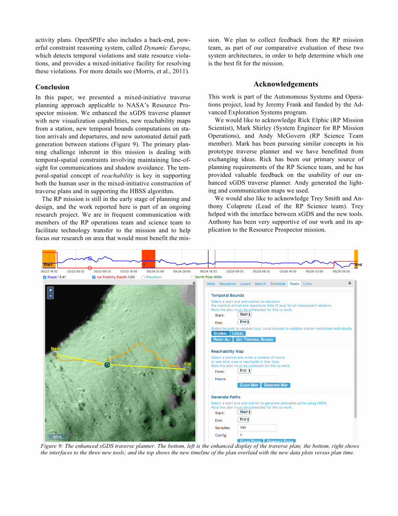
Conclusion In this paper, we presented a mixed-initiative traverse planning approach applicable to NASA’s Resource Pro-spector mission. We enhanced the xGDS traverse planner with new visualization capabilities, new reachability maps from a station, new temporal bounds computations on sta-tion arrivals and departures, and new automated detail path generation between stations (Figure 9). The primary plan-ning challenge inherent in this mission is dealing with temporal-spatial constraints involving maintaining line-of-sight for communications and shadow avoidance. The tem-poral-spatial concept of reachability is key in supporting both the human user in the mixed-initiative construction of traverse plans and in supporting the HBSS algorithm.
The RP mission is still in the early stage of planning and design, and the work reported here is part of an ongoing research project. We are in frequent communication with members of the RP operations team and science team to facilitate technology transfer to the mission and to help focus our research on area that would most benefit the mis-
sion. We plan to collect feedback from the RP mission team, as part of our comparative evaluation of these two system architectures, in order to help determine which one is the best fit for the mission.
Acknowledgements This work is part of the Autonomous Systems and Opera-tions project, lead by Jeremy Frank and funded by the Ad-vanced Exploration Systems program.
We would like to acknowledge Rick Elphic (RP Mission Scientist), Mark Shirley (System Engineer for RP Mission Operations), and Andy McGovern (RP Science Team member). Mark has been pursuing similar concepts in his prototype traverse planner and we have benefitted from exchanging ideas. Rick has been our primary source of planning requirements of the RP Science team, and he has provided valuable feedback on the usability of our en-hanced xGDS traverse planner. Andy generated the light-ing and communication maps we used.
We would also like to acknowledge Trey Smith and An-thony Colaprete (Lead of the RP Science team). Trey helped with the interface between xGDS and the new tools. Anthony has been very supportive of our work and its ap-plication to the Resource Prospector mission.
Figure 9: The enhanced xGDS traverse planner. The bottom, left is the enhanced display of the traverse plan; the bottom, right shows the interfaces to the three new tools; and the top shows the new timeline of the plan overlaid with the new data plots versus plan time.
References Andrews, D. R., Colaprete, A., Quinn, J., Chavers, D., and Picard, M. 2014. Introducing the Resource Prospector (RP) Mission. In Proceedings of the AIAA SPACE 2014 Conference and Exposi-tion. AIAA SPACE Forum. Bresina, J.L. 1996. Heuristic-Biased Stochastic Sampling. In Proceedings of the 13th AAAI Conference. Portland, OR. AAAI Press. Colaprete, A. 2014. Resource Prospector: A Lunar Volatiles Pro-specting and ISRU Demonstration Mission. NASA Exploration Science Forum. Cunningham, C., Jones, H., Kay, J., Peterson, K.M., Whittaker, W.L. 2014. Time-Dependent Planning for Resource Prospecting. In Proceedings of the International Symposium on Artificial Intel-ligence, Robotics and Automation in Space. Montreal, Canada. Deans, M., Marquez, J., Miller, M., Hoffman, J., Lim, D. 2017. Minerva: User-Centered Science Operations Software Capability for Future Human Exploration. In Proceedings of the IEE Aero-space Conference. Big Sky, Montana. IEEE. Fink, W., Baker, V.R., Flammia, M., Tarbell, M.A. 2015. Rover traverse-optimizing planner for multi-objective deployment sce-narios. In IEEE Aerospace Conference. Big Sky, MT. IEEE.
Heldmann, J.L., Colaprete, A., Elphic, R., Lim, D., Deans, M., Cook, A., Roush, T., Skok, J., Button, N., Karunatillake, S., Stok-er, C., Marquez. J., Shirley, M., Kobayashi, L., Lees, D., Bresina, J., Hunt, R. 2016. Lunar polar rover science operations: Lessons learned and mission architecture implications from the Mojave Volatiles Prospector terrestrial field campaign. In Advances in Space Research, Vol 58, Issue 4, pp. 545-559. Elsevier. Johnson, A.W., Hoffman, J.A., Newman, D.J., Mazarico, E.M., Zuber, M.T. 2010. An Integrated Traverse Planner and Analysis Tool for Planetary Exploration. In Proceedings of the AIAA SPACE 2010 Conference & Exposition. Anaheim CA. pp. 1-28. Morris, P., Bresina, J.L., Barreiro, J., Iaturo, M., Smith, T., 2011. State-Based Scheduling via Active Resource Solving. In Proceed-ings of the Fourth IEEE International Conference on Space Mis-sion Challenges for Information Technology. Palo Alto, CA, pp.29-34, IEEE. Otten, N.D., Jones, H.L., Wettergreen, D.S., Whittaker, W.L. 2015. Planning routes of continuous illumination and traversable slope using connected component analysis. In IEEE International Conference on Robotics and Automation, pp. 3953-3958. IEEE. Peng, Wu and Hehua, Ju. 2013. Mission-Integrated Path Planning for Planetary Rover Exploration. In Journal of Software, Volume 8, Number 10, pp. 2620-2627. Academy Publisher. Tompkins, P., Stentz, A., Wettergreen, D. 2004. Global path planning for Mars rover exploration. In Proceedings of the IEEE Aerospace Conference. Volume 6. IEEE.