Síndromes linfoproliferativos CD30+. Serie de 26 casos y ...

16-0809.01 5/14/2016 Page 1 of 7
TRAVERSE CITY LIGHT & POWER CD21 & CD30 POLE REPLACEMENT
REQUEST FOR BIDS Traverse City Light & Power (TCL&P) is requesting bids to provide all labor, equipment and material (majority of material is Owner-Furnished) necessary for the replacement of forty-seven poles. This project is being undertaken to replace poles that have been tested and marked for immediate replacement. The project is located both in the City of Traverse City and Garfield Township, Grand Traverse County, Michigan as shown on the construction drawings. All bidders must familiarize themselves with the site conditions prior to submitting a bid for this project. All work must be completed no later than September 30, 2016. TCL&P will furnish all of the material required for this project except stone backfill. Refer to the attached material list for specific material information. The successful bidder will be responsible for retrieving all Owner-furnished material from TCL&P’s warehouse and transporting it to the project locations. The successful Bidder will be required to execute the attached Contract Agreement and submit a Certificate of Insurance plus Performance and Payment Bonds (for the Total Contract Price) meeting the requirements stated in the Agreement. Bids must be submitted on a unit price basis on the attached forms. Bidders may submit alternate bids that reduce the total project cost, but must submit a unit price bid as well. All sales, consumer, use and other similar taxes required by law to be paid by the Contractor shall be included in the bid price. Sealed bids must be submitted no later than 11:00am, Wednesday, June 1, 2016 to the offices of TCL&P (address listed below), attn: Mr. Pete Schimpke. Electronic copies will not be accepted. Bidders are required to have an extensive record of successful medium voltage (15kV) overhead and underground projects for municipal, cooperative, or investor owned power utilities. Project record must include overhead line construction, medium voltage cable installation and termination, medium voltage padmount equipment installation, and fault indicator system installation & testing. Traverse City Light & Power reserves the right to accept or reject any bid, waive technicalities, and to accept the bid deemed to be in the best interest of TCL&P. Please address all questions to Mr. Michael McGeehan, 231.439.9683 (office) 231.330.2900 (cell.) Traverse City Light & Power GRP Engineering, Inc. 1131 Hastings Street 459 Bay Street Traverse City, MI 49686 Petoskey, MI 49770 231.932.4940 231.439.9683 231.922.4638 Fax Fax 231.439.9698
16-0809.01 5/14/2016 Page 2 of 7
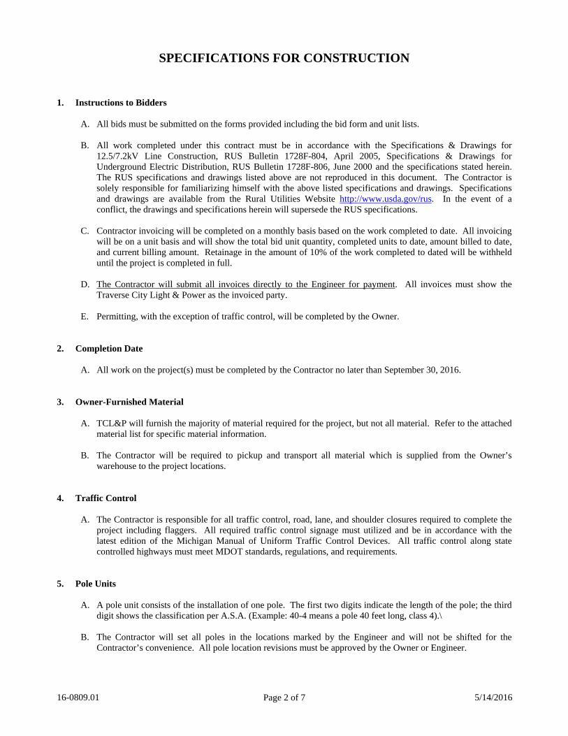
SPECIFICATIONS FOR CONSTRUCTION
1. Instructions to Bidders
A. All bids must be submitted on the forms provided including the bid form and unit lists.
B. All work completed under this contract must be in accordance with the Specifications & Drawings for 12.5/7.2kV Line Construction, RUS Bulletin 1728F-804, April 2005, Specifications & Drawings for Underground Electric Distribution, RUS Bulletin 1728F-806, June 2000 and the specifications stated herein. The RUS specifications and drawings listed above are not reproduced in this document. The Contractor is solely responsible for familiarizing himself with the above listed specifications and drawings. Specifications and drawings are available from the Rural Utilities Website http://www.usda.gov/rus. In the event of a conflict, the drawings and specifications herein will supersede the RUS specifications.
C. Contractor invoicing will be completed on a monthly basis based on the work completed to date. All invoicing
will be on a unit basis and will show the total bid unit quantity, completed units to date, amount billed to date, and current billing amount. Retainage in the amount of 10% of the work completed to dated will be withheld until the project is completed in full.
D. The Contractor will submit all invoices directly to the Engineer for payment. All invoices must show the
Traverse City Light & Power as the invoiced party.
E. Permitting, with the exception of traffic control, will be completed by the Owner. 2. Completion Date
A. All work on the project(s) must be completed by the Contractor no later than September 30, 2016.
3. Owner-Furnished Material
A. TCL&P will furnish the majority of material required for the project, but not all material. Refer to the attached material list for specific material information.
B. The Contractor will be required to pickup and transport all material which is supplied from the Owner’s
warehouse to the project locations. 4. Traffic Control
A. The Contractor is responsible for all traffic control, road, lane, and shoulder closures required to complete the project including flaggers. All required traffic control signage must utilized and be in accordance with the latest edition of the Michigan Manual of Uniform Traffic Control Devices. All traffic control along state controlled highways must meet MDOT standards, regulations, and requirements.
5. Pole Units
A. A pole unit consists of the installation of one pole. The first two digits indicate the length of the pole; the third digit shows the classification per A.S.A. (Example: 40-4 means a pole 40 feet long, class 4).\
B. The Contractor will set all poles in the locations marked by the Engineer and will not be shifted for the
Contractor’s convenience. All pole location revisions must be approved by the Owner or Engineer.

16-0809.01 5/14/2016 Page 3 of 7
C. Thoroughly backfill and tamp full depth all pole holes. Bank up earth around each pole except in residential areas where poles are located in finished lawn areas. After completion of job, inspect holes, and refill any settlement.
D. Additional payment will not be made for poles required to be set in wet areas utilizing the “wet hole” method.
The Contractor will familiarize himself with each project section to determine if the “wet hole” method” will be required.
E. All stone backfill required for the TM-101, TM-102, & TM-103 will be supplied by the Contractor. Cost for
this material must be included in the labor column for these units.
F. Deadend and corner poles will be raked ¼” per foot of pole exposed above grade in a direction away from the line tension.
G. Owner and Engineer will coordinate the transfer of all communication cables to new poles. Contractor will cut
the pole tops of poles with communications cables directly above the system neutral. In the event the communications cables are not transferred prior to the Contractor demobilizing, the Contractor will invoice the Owner on a Cut Pole Top unit and not a full pole removal unit.
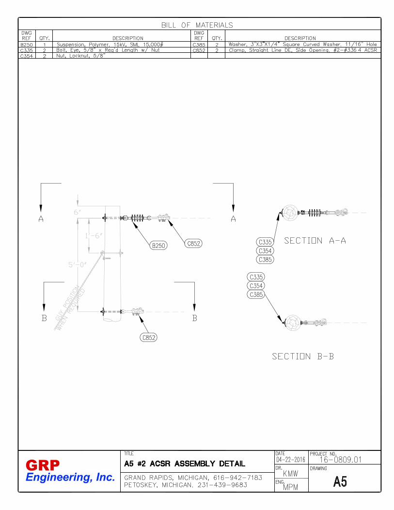
6. Pole Top Assembly Units
A. A pole top assembly unit consists of the installation of the hardware, crossarms and their appurtenances, insulators, etc., including tie wire, required to support the primary conductors.
B. The Contractor will install M5-5 jumper supports as necessary on deadend and corner poles to adequately hold
jumpers from contacting grounded surfaces.
C. Maintain a minimum of 2” between all ungrounded pole hardware and the pole ground downlead.
D. All bolts will extend a minimum of ½” but not more than 2-1/2” beyond the nuts. Any bolt cut will be rethreaded by the Contractor.
7. Conductor Assembly Units
A. A conductor assembly unit consists of the installation of 1.0 foot of conductor or cable for primaries, secondaries or services. The Bill of Materials lists conductor footage based on the horizontal distance between poles plus an additional 3% for sag.
B. All conductor will be strung under tension according to the stringing charts included herein. The Contractor
must take a precautions necessary to insure the conductor does not touch the ground, energized equipment or conductors, or buildings during stringing operations.
C. All Hendrix aerial spacer cable systems must be installed according to the manufacturers’ instructions.
8. Guy Assembly Units
A. A guy assembly unit consists of the installation of the hardware and wire, guy marker, and guy insulator where necessary. An overhead guy assembly unit does not include the associated pole and anchor, each of which is listed separately.
B. All guy wire will be 10M Alumoweld. C. Guy wire will be deadended with pre-formed grips sized appropriately for the specified guy strand.
16-0809.01 5/14/2016 Page 4 of 7
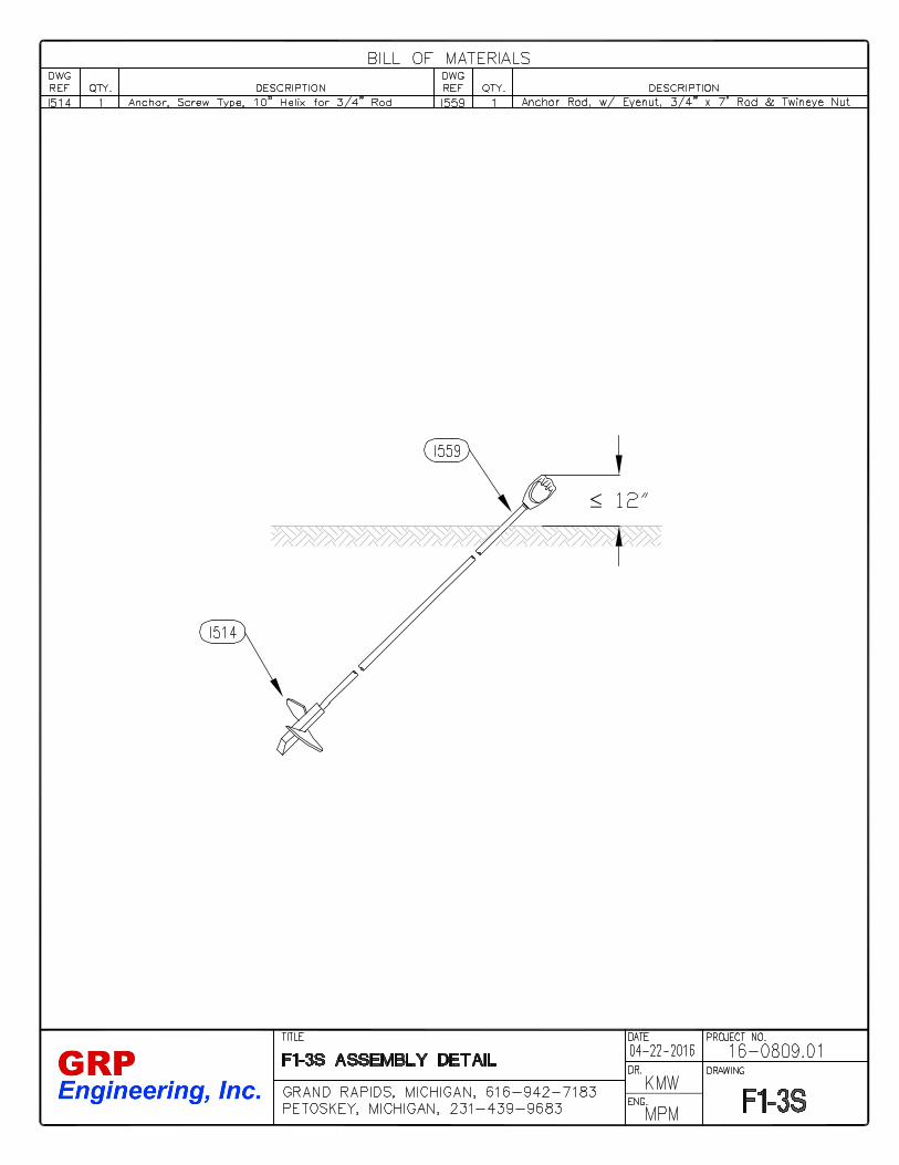
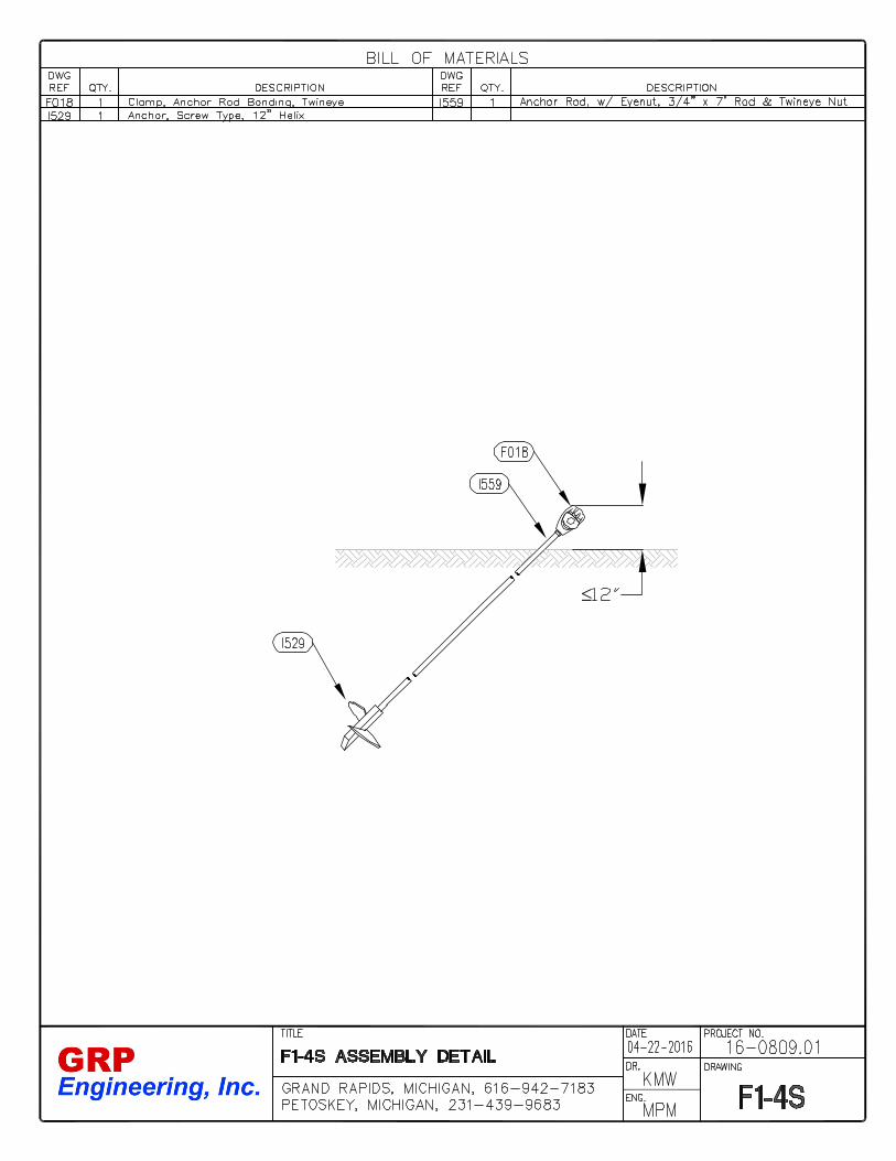
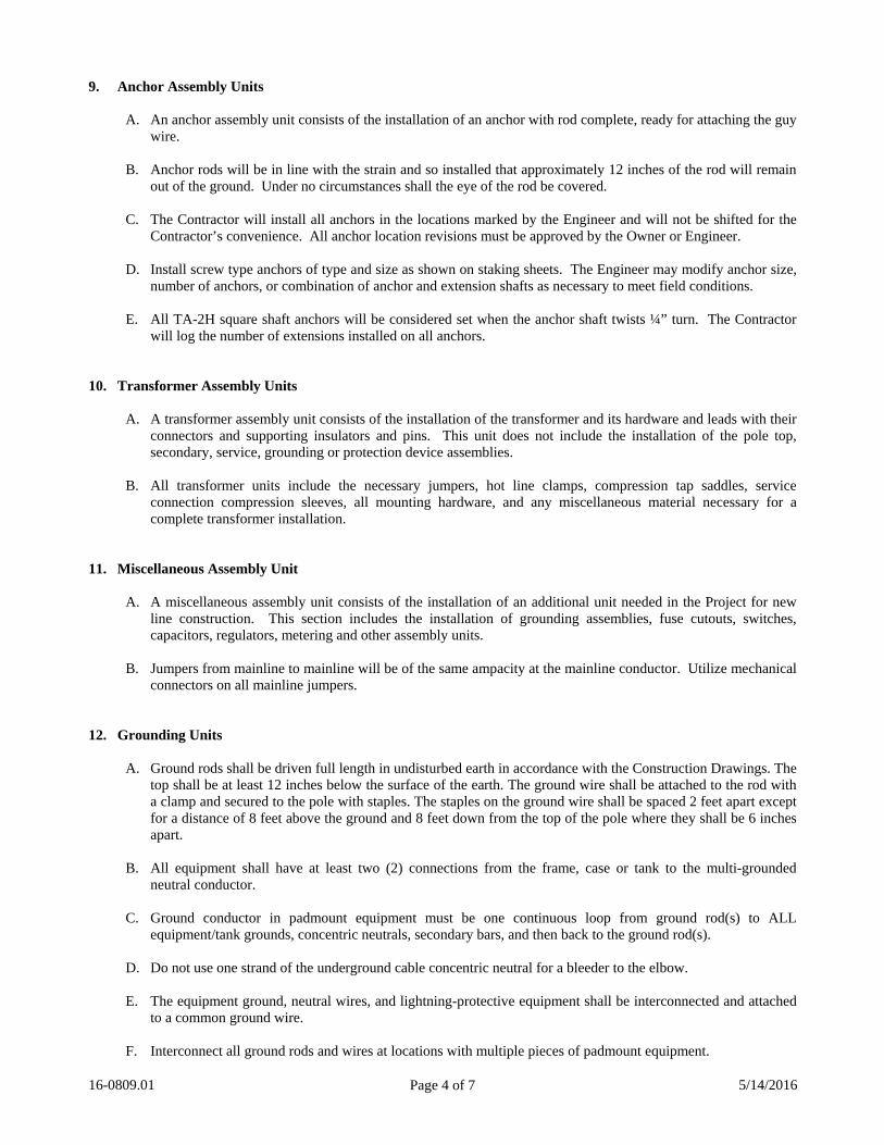
9. Anchor Assembly Units
A. An anchor assembly unit consists of the installation of an anchor with rod complete, ready for attaching the guy wire.
B. Anchor rods will be in line with the strain and so installed that approximately 12 inches of the rod will remain
out of the ground. Under no circumstances shall the eye of the rod be covered. C. The Contractor will install all anchors in the locations marked by the Engineer and will not be shifted for the
Contractor’s convenience. All anchor location revisions must be approved by the Owner or Engineer.
D. Install screw type anchors of type and size as shown on staking sheets. The Engineer may modify anchor size, number of anchors, or combination of anchor and extension shafts as necessary to meet field conditions.
E. All TA-2H square shaft anchors will be considered set when the anchor shaft twists ¼” turn. The Contractor
will log the number of extensions installed on all anchors.
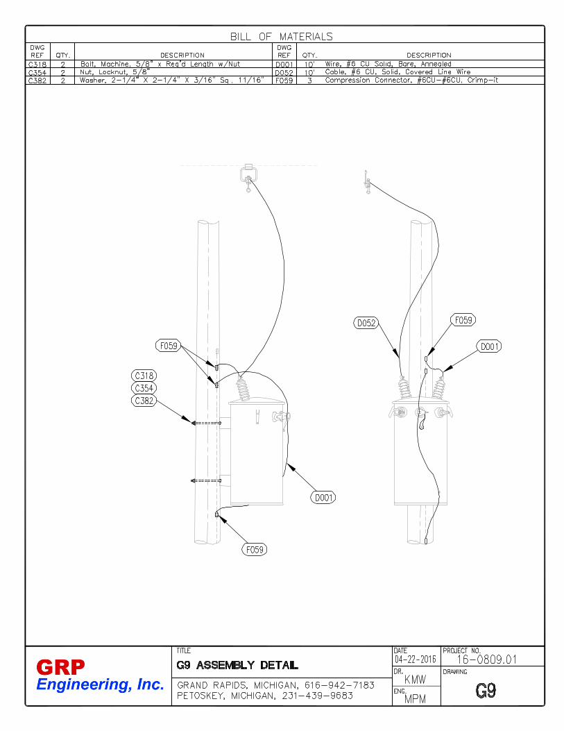
10. Transformer Assembly Units
A. A transformer assembly unit consists of the installation of the transformer and its hardware and leads with their connectors and supporting insulators and pins. This unit does not include the installation of the pole top, secondary, service, grounding or protection device assemblies.
B. All transformer units include the necessary jumpers, hot line clamps, compression tap saddles, service
connection compression sleeves, all mounting hardware, and any miscellaneous material necessary for a complete transformer installation.
11. Miscellaneous Assembly Unit
A. A miscellaneous assembly unit consists of the installation of an additional unit needed in the Project for new line construction. This section includes the installation of grounding assemblies, fuse cutouts, switches, capacitors, regulators, metering and other assembly units.
B. Jumpers from mainline to mainline will be of the same ampacity at the mainline conductor. Utilize mechanical
connectors on all mainline jumpers. 12. Grounding Units
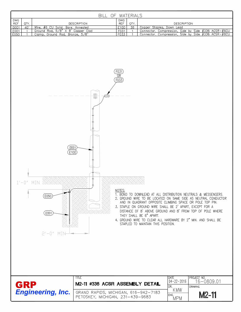
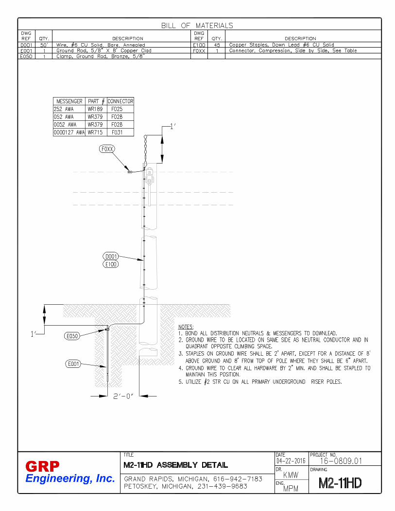
A. Ground rods shall be driven full length in undisturbed earth in accordance with the Construction Drawings. The top shall be at least 12 inches below the surface of the earth. The ground wire shall be attached to the rod with a clamp and secured to the pole with staples. The staples on the ground wire shall be spaced 2 feet apart except for a distance of 8 feet above the ground and 8 feet down from the top of the pole where they shall be 6 inches apart.
B. All equipment shall have at least two (2) connections from the frame, case or tank to the multi-grounded
neutral conductor.
C. Ground conductor in padmount equipment must be one continuous loop from ground rod(s) to ALL equipment/tank grounds, concentric neutrals, secondary bars, and then back to the ground rod(s).
D. Do not use one strand of the underground cable concentric neutral for a bleeder to the elbow.
E. The equipment ground, neutral wires, and lightning-protective equipment shall be interconnected and attached
to a common ground wire.
F. Interconnect all ground rods and wires at locations with multiple pieces of padmount equipment.

16-0809.01 5/14/2016 Page 5 of 7
G. Tie all concentric neutrals together before tapping to ground loop to assure the same conductivity as the cable
neutral. 13. Removal Assembly Units
A. The Contractor will deliver all salvageable material which includes all poles 10 years old or less, transformers, conductor, cutouts, and OCR’s to the Owner’s warehouse. Verify with the Owner if any other material will be salvaged.
B. The Contractor will assume ownership of and responsibility for all other removed materials. All material will
be removed from the Project site. The Contractor will not bury non-salvaged material in pole holes or other locations on site.
C. All pole holes, where poles have been removed, must be backfilled and tamped to grade.
D. Removal assembly units cover the furnishing of all labor for the removal of existing units of construction from
existing lines, disassembling into salvageable items, and all labor and transportation for the returning of those salvageable items to the Owner’s warehouse.
The unit removal prices will include all labor required to reinstall in accordance with specifications any
conductors temporarily detached. The Contractor will reinstall at his own expense any other units removed by him for his own convenience.
The following special notes apply to specific removal units:
a. Poles. All poles of the same height, regardless of class, are designated by the same unit. Thus a 30 on the removal staking sheets signifies the removal of a 30-foot pole of any class. The Contractor is not require under this unit to remove from the pole any ground wire or pole numbering attached to the pole. This unit includes the refilling and tamping of holes in a workmanlike manner unless they are to be reused.
b. Pole-top Assemblies. The unit removal of pole-top assemblies includes, in addition to the removal of
the assembly itself, any necessary handling, resagging, and retying of conductors in those cases where an existing pole-top assembly will be removed and replaced by a new pole-top assembly and where any existing conductor is to be reused.
The unit of removal of pole-top assemblies also included any holding or handling of mainline or tap conductors at tap lines, angles, and deadends where such is involved, and the reinstalling of such conductor in accordance with the Specifications; for example, an A5-4 will include the disconnection of the tap conductors, snubbing off the tap line at the nearest practical point and the reconnection and resagging of these tap conductors if necessary to the new tap assembly when installed. The new unit of construction, however, will be specified separately in the New Construction section.
c. Conductor. The conductor removal unit covers the removal of 1.0 linear foot of conductor or cable
and reeling or coiling it in a workmanlike manner in such a way that it can be recycled. d. Guys. All guys regardless of length, type of attachment, or size of guy strand are specified by the same
unit; thus an E on the removal staking sheets signifies the removal of any guy.
e. Anchors. All anchors are to be removed from the ground by the Contractor. An F on the removal staking sheets signifies the removal of any anchor.
f. Transformers. Only one transformer unit is specified and all sizes of transformers from 1 to 50kVA
are covered by the same unit.

16-0809.01 5/14/2016 Page 6 of 7
g. Secondary Units. The unit for removal of secondary assemblies includes, in addition to the removal of the assembly itself, all necessary handling such as untying, resagging, and retying of secondary conductor or cables where existing secondary conductor or cable is to be reused.
In addition, the unit for removal of the secondary assembly includes the handling or holding of any conductor at tap lines where such is involved, and the reinstalling of such tap conductor in accordance with the Specifications.
h. Service Units. The unit for removal of service assemblies includes, in addition to the removal of the
assembly itself, all necessary handling such as untying, resagging, and retying of service conductor or cables where existing service conductor or cable is to be reused.
14. Outages
A. Although the work under this contract is scheduled to be completed with the primary system energized, should any primary outage be required, the Contractor shall provide a minimum of 48 hours notice to the Owner. The Contractor will coordinate all outages with the Owner and all affected customers.
B. Coordinate all switching operations with the Owner.
15. Transfer Units – Transfer units include all labor necessary to remove the complete assembly unit from an existing
pole to a new pole. This includes all necessary conductor handling to complete the transfer including temporary means to maintain an energized system (e.g. installation of insulated jumpers “macks”) and reconnection on the new pole. All transfer and splice units for underground construction include excavation necessary to complete the work.
16. Fusing & Sectionalizing
A. All fusing and sectionalizing instructions will be given to the Contractor by the Owner. Fuses will be furnished by the Owner to the Contractor at no cost. The Contractor will record all sectionalizing and fuse sizes and settings on the record drawings.
17. Safety Rules
A. The Contractor shall have a written safety program in place to adequately protect their employees from workplace hazards. Written documentation of the safety program and employee trainings shall be made available to TCL&P upon request. The Contractor is ultimately responsible for the safety of all Contractor employees while completing the project(s).
B. TCL&P reserves the right to stop work on the project(s) immediately following any contractor related injury or
accident during the accident investigation period. 18. Leaving the Project(s) for Extended Time Periods
A. Following commencement of work on the project(s), the Contractor shall not abandon the Project for an extended length of time unless granted written permission from the Owner. The Owner will review the project schedule to verify that the Contractor has provided sufficient crews and equipment to keep the project on schedule prior to granting permission to leave for an extended time period. The Owner’s intent is to insure the Contractor is progressing throughout the duration of the Project.
B. Should the Contractor abandon the Project for greater than five working days, the Contractor must leave the
Project in a safe and reliable state. This includes but is not limited to:
a. All conductors removed from hot or temporary arms and secured to insulators and pole. b. Poles and associated material moved to a safe zone approved by the Owner.

16-0809.01 5/14/2016 Page 7 of 7
c. All leaned poles shall be secured. d. Secure all temporary jumpers and apparatuses and obtain Owner approval on method used to secure. e. All Contractor owned vehicles and equipment removed from the project site and moved to an area
approved by the Owner.
C. Should the Contractor leave the project and not comply with the items above, the Owner retains the right to complete those incomplete items and charge the Contractor for all labor and equipment time and material utilized. This includes payment to outside contractors to complete the required work.
19. Contract Date Extensions
A. All requests for contract date extensions shall be written requests and submitted to the Owner.
B. Extensions requests based on weather related delays shall include documentation provided by the Contractor of non-working days due to inclement weather.
Version 1/5/16
1
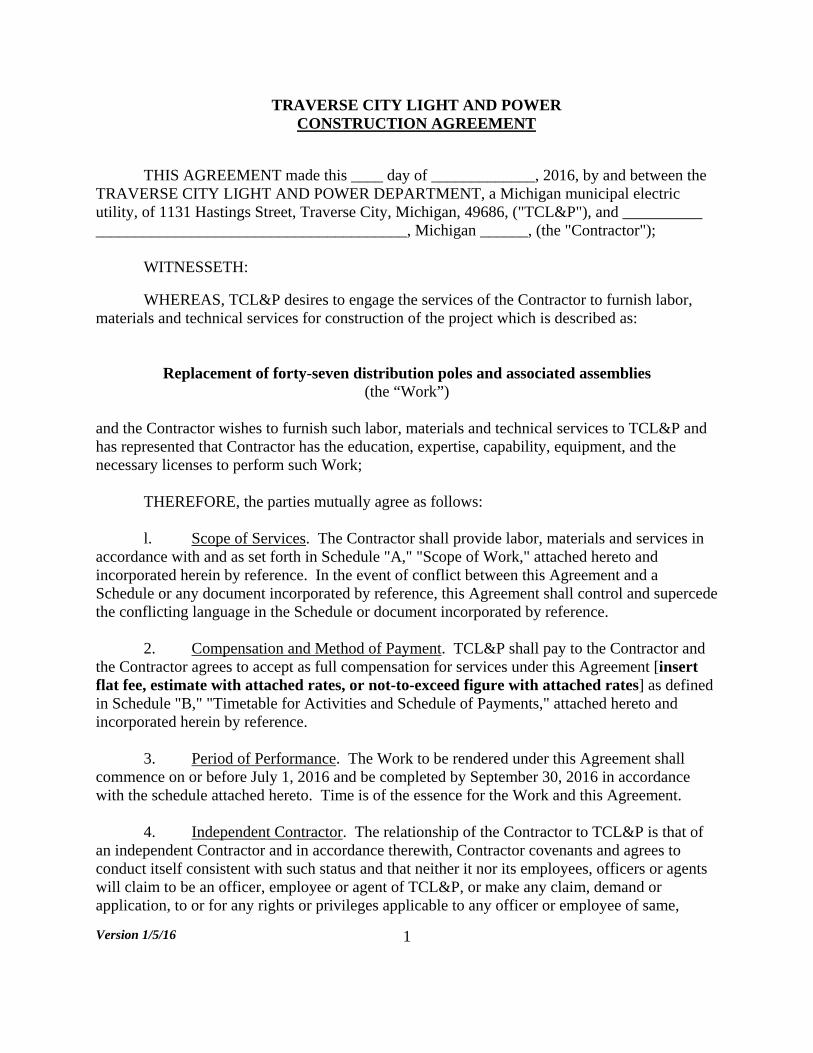
TRAVERSE CITY LIGHT AND POWER CONSTRUCTION AGREEMENT
THIS AGREEMENT made this ____ day of _____________, 2016, by and between the TRAVERSE CITY LIGHT AND POWER DEPARTMENT, a Michigan municipal electric utility, of 1131 Hastings Street, Traverse City, Michigan, 49686, ("TCL&P"), and __________ _______________________________________, Michigan ______, (the "Contractor");
WITNESSETH:
WHEREAS, TCL&P desires to engage the services of the Contractor to furnish labor, materials and technical services for construction of the project which is described as:
Replacement of forty-seven distribution poles and associated assemblies (the “Work”)
and the Contractor wishes to furnish such labor, materials and technical services to TCL&P and has represented that Contractor has the education, expertise, capability, equipment, and the necessary licenses to perform such Work; THEREFORE, the parties mutually agree as follows: l. Scope of Services. The Contractor shall provide labor, materials and services in accordance with and as set forth in Schedule "A," "Scope of Work," attached hereto and incorporated herein by reference. In the event of conflict between this Agreement and a Schedule or any document incorporated by reference, this Agreement shall control and supercede the conflicting language in the Schedule or document incorporated by reference. 2. Compensation and Method of Payment. TCL&P shall pay to the Contractor and the Contractor agrees to accept as full compensation for services under this Agreement [insert flat fee, estimate with attached rates, or not-to-exceed figure with attached rates] as defined in Schedule "B," "Timetable for Activities and Schedule of Payments," attached hereto and incorporated herein by reference. 3. Period of Performance. The Work to be rendered under this Agreement shall commence on or before July 1, 2016 and be completed by September 30, 2016 in accordance with the schedule attached hereto. Time is of the essence for the Work and this Agreement. 4. Independent Contractor. The relationship of the Contractor to TCL&P is that of an independent Contractor and in accordance therewith, Contractor covenants and agrees to conduct itself consistent with such status and that neither it nor its employees, officers or agents will claim to be an officer, employee or agent of TCL&P, or make any claim, demand or application, to or for any rights or privileges applicable to any officer or employee of same,
Version 1/5/16
2
including, but not limited to worker's compensation coverage, unemployment insurance benefits, social security coverage, or retirement membership or credit.
5. Contractor Responsibility. The Contractor shall perform the Work in a good and workmanlike manner and assumes the risk in performing under this Agreement. Contractor shall be solely responsible and answerable in damages for all improper Work, accidents or injuries to person or property. Contractor shall make a careful examination of the site, plans, specifications and all conditions affecting the Work, and any failure to make such examination will not be a valid excuse for failure to do the Work as a basis for any claim for extra compensation or extension of time. 6. Indemnity. Contractor shall defend, indemnify and save harmless TCL&P, its officers and employees, from and against any and all claims, liabilities, losses, damages, actual attorneys' fees and settlement expenses for injury or death, or, any person and damage, or loss of any property allegedly or actually resulting or arising out of any act, omission, or negligence of Contractor or its employees, agents or subcontractors in connection with performing this Agreement, or resulting from or arising out of the joint negligence of TCL&P and that of Contractor or any other person or entity. TCL&P shall not be indemnified against liability for damages arising out of bodily injury or damage to property where the entire amount of such damage, whether recoverable or not, is caused by or resulted from the sole negligence of TCL&P, its officers or employees. This indemnification agreement shall not be limited by reason of any insurance coverage.
7. Bonds. The Contractor shall, at the time of execution hereof by TCL&P, provide a performance bond in an amount of not less than one-hundred percent (100%) of the contract price in favor of TCL&P, conditioned upon the faithful performance of the contract and completion on or before the date specified; and a labor and material bond running to TCL&P in an amount of not less than one-hundred percent (100%) of the contract price for the protection of subcontractors, material suppliers and labor. The bonds shall be in substantially the same form as the current AIA bond forms, or in such other form as is approved by TCL&P's General Counsel. The TCL&P may waive the requirement for these bonds if the contract is less than $50,000 and the signature of the Executive Director appearing at the end of this paragraph shall be deemed to be a waiver of the bond requirements. ________________________________ Timothy J. Arends, Executive Director
8. Insurance. The Contractor shall acquire and maintain comprehensive general liability insurance coverage. The limits and deductible shall be as follows:
A. Comprehensive General Liability insurance coverage. $2,000,000 minimum coverage.

Version 1/5/16
3
B. Owners and Contractors Protective Liability insurance coverage $2,000,000 minimum coverage. [omit this if the work does not justify this coverage.]
C. Comprehensive Automobile Liability insurance coverage $2,000,000
minimum coverage. The Contractor agrees not to change such insurance and agrees to maintain such insurance throughout the period of performance of this Agreement. Contractor will upon execution of this Agreement provide a certificate of insurance to the TCL&P Controller. Such certificate shall name TCL&P as an additional named insured with the broad form endorsement for ongoing operations and completed operations on the insurance policies for general liability, excess liability, and contractor liability. Contractor shall also provide Additional Insured Endorsement CG 20330413 or its equivalent. If any of the required insurance is not renewed or canceled, the Contractor and all subcontractors shall cease operations and shall not resume until new insurance is obtained. Contractor shall obtain Third Party Notice Endorsement IL 79901010 for each required policy requiring the insurer to give Owner 30 days’ notice of non-renewal or cancellation. 9. Workers' Compensation. The parties shall maintain suitable workers' compensation insurance pursuant to Michigan law and Contractor shall provide a certificate of insurance or copy of state approval for self-insurance to the TCL&P Controller upon execution of this Agreement. 10. Compliance with Regulations. The Contractor shall familiarize itself with and comply with all applicable statutes, rules and regulations of all Federal, State and local governments and agencies having jurisdiction, and bears the risk of any such authorities or changes thereto. 11. Standard of Conduct. Contractor shall tender all services under this Agreement according to generally accepted professional practices for the intended use of the Work. 12. TCL&P's Obligation. TCL&P shall provide Contractor with all information currently available to it upon request of the Contractor. TCL&P's Executive Director or such other person as the Executive Director shall designate shall be TCL&P's representative for purposes of this Agreement. 13. Non-Discrimination. The Contractor agrees not to discriminate against an employee or applicant for employment with respect to hire, tenure, terms, conditions or privileges of employment, or a matter directly or indirectly related to employment because of their actual or perceived race, color, religion, national origin, age, sex, height, weight, marital status, physical or mental disability, family status, sexual orientation, or gender identity. Breach of this covenant may be regarded as a material breach of this contract. The Contractor agrees to require similar provisions from any sub-contractor.

Version 1/5/16
4
14. Prohibition Against Assignment. This Agreement is intended to secure the service of Contractor because of its ability and reputation and none of the Contractor's duties under the Agreement shall be assigned, subcontracted, or transferred without the prior written consent of the TCL&P Executive Director. Any assignment, subcontract or transfer of Contractor's duties under this Agreement must be in writing. 15. Third-Party Participation. The Contractor agrees that despite any subcontract entered into by the Contractor for execution of activities or provision of services related to the completion of this project, the Contractor shall be solely responsible for carrying out the project pursuant to this Agreement. The Contractor shall specify in any such subcontract that the subcontractor shall be bound by this Agreement and any other requirements applicable to the Contractor in the conduct of the project, unless TCL&P and the Contractor agree to modification in a particular case. The Contractor shall not subcontract unless agreed upon in writing by TCL&P’s Executive Director. 16. Interest of Contractor. The Contractor represents that its officers and employees have no interest and covenant that they will not acquire any interest, direct or indirect, which would conflict in any manner or degree with the performance of Contractor's services and duties hereunder. The Contractor further covenants that in the performance of the Agreement, no person having any such interest shall be employed, Contractor further covenants that neither it nor any of its principals are in default to the City of Traverse City. 17. Covenant Against Contingent Fees. The Contractor warrants that no person or selling agency has been employed or retained to solicit or secure this contract upon any agreement or understanding for a commission, percentage, brokerage, or contingent fee, excepting bona fide employees. For breach of violation of this warranty, TCL&P shall have the right to annul this Agreement without liability, or in its discretion, to deduct from the contract price or consideration, or otherwise recover the full amount of such commission, percentage, brokerage, or contingent fee. 18. Qualifications of the Contractor. The Contractor specifically represents and agrees that its officers, employees, agents and consultants have and shall possess the experience, knowledge, and competence necessary to qualify them individually for the particular duties they perform hereunder. 19. Electronic Transactions. The parties agree to conduct this transaction by electronic means. This Agreement may be executed by providing an electronic signature under the terms of the Uniform Electronic Transactions Act. This Agreement may not be denied legal effect or admissibility as evidence solely because it is in electronic form, permits the completion of the business transaction referenced herein electronically instead of in person, or has been stored electronically. As an alternative to physical delivery, any document, including any signed document or written notice, may be delivered in electronic form only. Documents with original signatures shall be provided upon request of any party.
Version 1/5/16
5
20. Notice. Notices pursuant to this Agreement shall be given to TCL&P as follows: _________________ 1131 Hastings Street Traverse City, MI 49686 (231) 922-____ ext. ___ @tclp.org
Notices pursuant to this Agreement shall be given to Contractor as follows:
___________________ ___________________ ___________________ (___) ______________ _____@____________
21. Amendments. This Agreement may be modified fiom time to time, but such modifications must be in writing and signed by both parties. 22. Termination for Fault. If TCL&P determines that the Contractor has failed to perform or will fail to perform all or any part of the services, obligations, or duties required by this Agreement, TCL&P may terminate or suspend this Agreement in whole or in part upon written notice to the Contractor specifying the portions of the Agreement and in the case of suspension shall specify a reasonable period not more than thirty (30) days nor less than fifteen (15) days from receipt of the notice, during which time the Contractor shall correct the violations referred to in the notice. If the Contractor does not correct the violations during the period provided for in the notice, this Agreement shall be terminated upon expiration of such time. Upon termination, any payment due the Contractor at time of termination may be adjusted to cover TCL&P’s additional costs occasioned by reason of the termination. This provision for termination shall not limit or modify any other right of TCL&P to proceed against the Contractor at law or under the terms of this Agreement. 23. Force Majeure. If because of Force Majeure, either party is unable to carry out any of its obligations under this agreement (other than obligations of such party to pay or expend money for or in connection with the performance of this Agreement), and if such party promptly gives to the other party concerned written notice of such force majeure, then the obligations of the party giving such notice will be suspended to the extent made necessary by such force majeure and during its continuance, provided the effect of such force majeure is eliminated insofar as possible with all reasonable dispatch. "Force Majeure" means unforeseeable events beyond a party's reasonable control and without such party's fault or negligence, including, but not limited to, acts of God, acts of public enemy, acts of the federal government, acts of another party to this Agreement, fire, flood, inclement weather, epidemic, quarantine restrictions, strikes and embargoes, labor disturbances, the unavailability of raw materials, legislation, charter amendments or referendum, orders or acts of civil or military authority, injunctions, or other causes of a similar nature which wholly or substantially prevent performance. TCL&P may terminate this Agreement because of Force Majeure and the Contractor shall be entitled to and

Version 1/5/16
6
TCL&P shall pay the costs actually incurred in compliance with this Agreement until the date of such termination. 24. Delay. If the Contractor is delayed in the completion of the Work due to acts of TCL&P or due to Force Majeure, the time for completion shall be extended for a period determined by TCL&P to be equivalent to the time of such delay. The Contractor shall not be entitled to recover damages or costs sustained by reason of such delays. 25. Interpretation. This Agreement shall be governed by the laws of the State of Michigan, both as to interpretation and performance. The pronouns and relative words used herein are written in the neuter and singular. However, if more than one person or entity joins in this Agreement on behalf of Contractor, or if a person of masculine or feminine gender joins in this Agreement on behalf of Contractor, such words shall be interpreted to be in the plural, masculine or feminine as the sense requires. 26. Venue. Any and all suits for any and every breach of this Agreement may be instituted and maintained in any court of competent jurisdiction in the County of Grand Traverse, State of Michigan. 27. Entire Agreement. This Agreement, together with all items incorporated herein by reference, constitutes the entire agreement of the parties and there are no valid promises, conditions or understandings which are not contained herein. It is understood that should Contractor recommend further work concerning the project, TCL&P is under no obligation to engage Contractor in such work. 28. Authority to Execute. The parties agree that the signatories appearing below have the authority and are duly authorized to execute this Agreement on behalf of the party to the Agreement. 29. Counterparts. This Agreement may be signed in one or more counterparts, and each counterpart will be considered an original Agreement. All of the counterparts will be considered one document and become a binding agreement when one or more counterparts have been signed by each of the parties and delivered to the other. 30. No Third Party Beneficiaries. This Agreement confers no rights or remedies on any third-party, other than the parties to this Agreement, and their respective successors and permitted assigns. 31. No Joint Venture or Partnership. This Agreement does not and is not intended to create a joint venture or partnership between the parties. The rights and obligations of the parties are entirely contained within this Agreement.
Version 1/5/16
7
IN WITNESS WHEREOF, the parties hereto have executed this Agreement on the date and year first above written. TRAVERSE CITY LIGHT AND POWER DEPARTMENT ______________________________ John Taylor, Chairman ______________________________ Timothy J. Arends, Secretary ________________(Contractor) ______________________________ , ___________ ______________________________ APPROVED AS TO SUBSTANCE: ______________________________ Timothy J. Arends Executive Director APPROVED AS TO FORM: ______________________________ W. Peter Doren General Counsel

Version 1/5/16
8
SCHEDULE A
SCOPE OF WORK
The parties agree that the Work for TCL&P shall consist of the following:

Version 1/5/16
9
SCHEDULE B
TIMETABLE FOR ACTIVITIES Contractor shall commence the Work July 1, 2016. The schedule of activities shall follow the "Work Plan Schedule" attached as part of Schedule B, incorporated herein by reference. Services shall be completed not later than September 30, 2016.
SCHEDULE OF PAYMENTS Payments shall be made to the Contractor as follows:
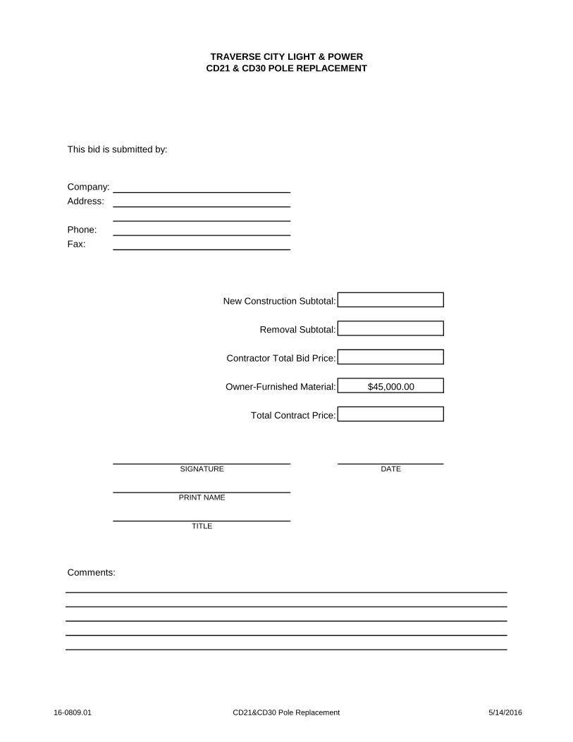
TRAVERSE CITY LIGHT & POWERCD21 & CD30 POLE REPLACEMENT
This bid is submitted by:
Company:
Address:
Phone:
Fax:
New Construction Subtotal:
Removal Subtotal:
Contractor Total Bid Price:
Owner-Furnished Material: $45,000.00
Total Contract Price:
SIGNATURE DATE
PRINT NAME
TITLE
Comments:
16-0809.01 CD21&CD30 Pole Replacement 5/14/2016

TRAVERSE CITY LIGHT & POWERCD21 & CD30 POLE REPLACEMENT
NEW CONSTRUCTION UNIT LIST
UNIT EXTENDEDUNIT ITEM DESCRIPTION UNIT QUANTITY PRICE TOTAL
35-4 EA 19
40-4 EA 8
45-3 EA 1
45-4 EA 10
50-3 EA 8
55-3 EA 1
A1 EA 5
A2 EA 1
A5 EA 5
A5-3 EA 2
A9-1 EA 2
C1-2 EA 10
C7A EA 7
C8-2 EA 1
HD-T-14 EA 3
E1-3Fi EA 2
E1-3i EA 12
E2-3Fi EA 3
E2-3i EA 8
5.0' EXT. EA 3
F1-3S EA 8
F4-1S EA 2
TA-2H EA 3
G9 EA 6
Transfer G25DB240 EA 6
#1/0 USE LFT 150
#2 TX LFT 332
Transfer #1/0 USE EA 7
Transfer #1/0 USE QX EA 1
Transfer #2 QX EA 1
Transfer #2 TX EA 21
Transfer #4 TX EA 58
Transfer #4/0 TX EA 1
Transfer #6 DX EA 9
Transfer #6 TX EA 1
Transfer 1OWS EA 3
Transfer 2OWS EA 2
Transfer 3OWS EA 18
UM45-3 1/0 EA 6
UM45-3 2 EA 3
K10 EA 3
K14 EA 109
M2-11 EA 26
16-0809.01 CD21 & CD30 Poles New - 1 5/16/2016
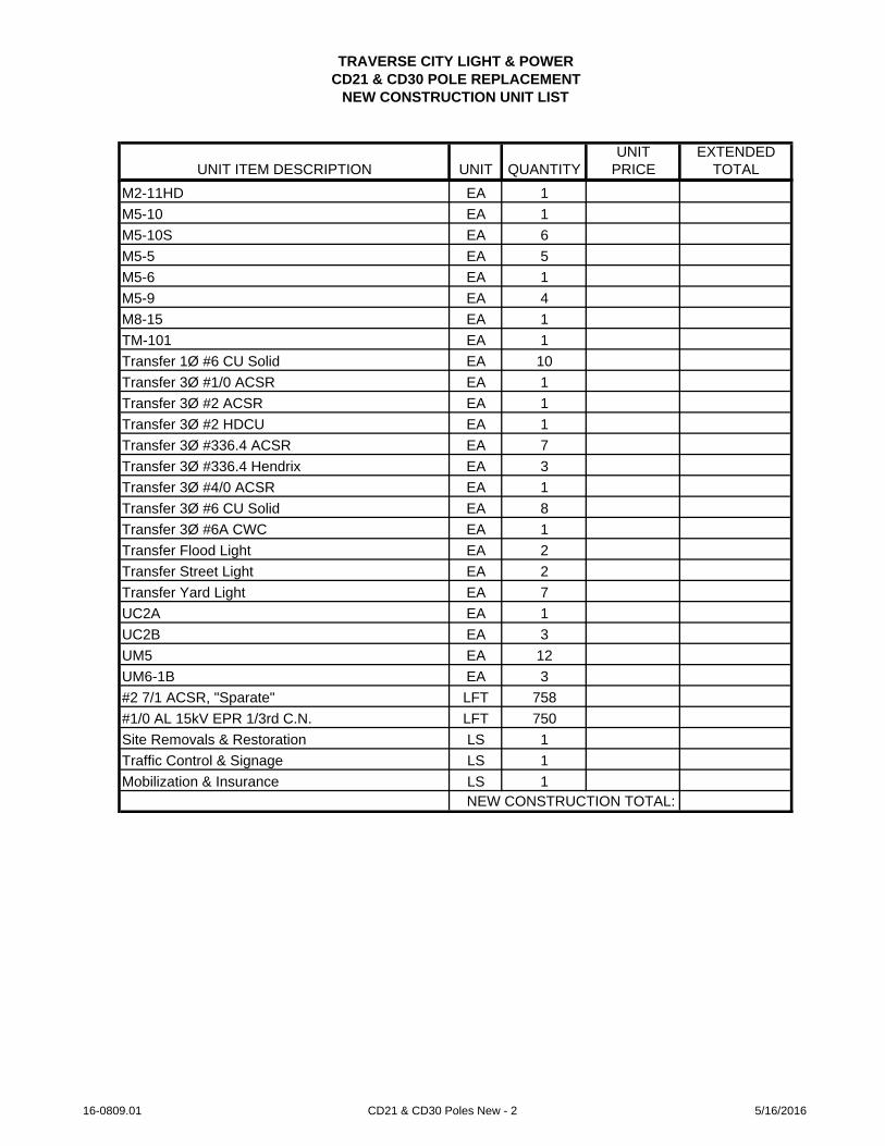
TRAVERSE CITY LIGHT & POWERCD21 & CD30 POLE REPLACEMENT
NEW CONSTRUCTION UNIT LIST
UNIT EXTENDEDUNIT ITEM DESCRIPTION UNIT QUANTITY PRICE TOTAL
M2-11HD EA 1
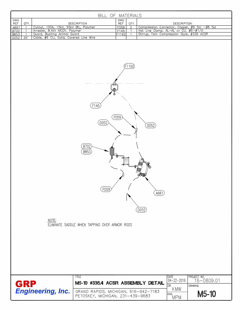
M5-10 EA 1
M5-10S EA 6
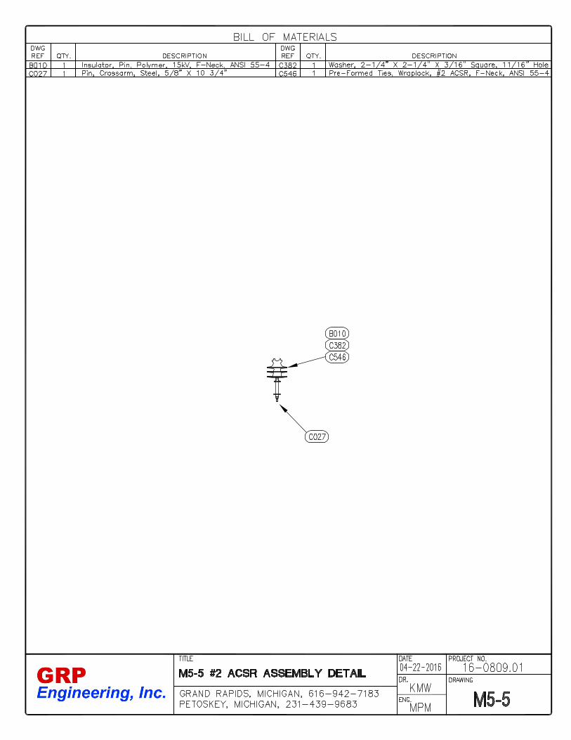
M5-5 EA 5
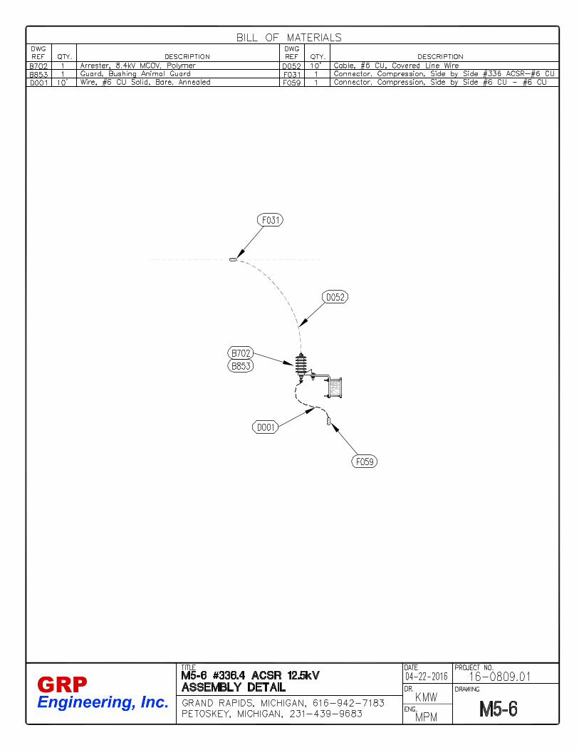
M5-6 EA 1
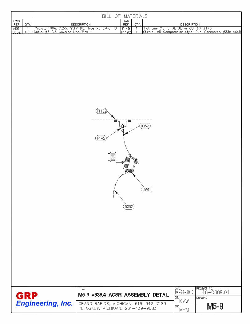
M5-9 EA 4
M8-15 EA 1
TM-101 EA 1
Transfer 1Ø #6 CU Solid EA 10
Transfer 3Ø #1/0 ACSR EA 1
Transfer 3Ø #2 ACSR EA 1
Transfer 3Ø #2 HDCU EA 1
Transfer 3Ø #336.4 ACSR EA 7
Transfer 3Ø #336.4 Hendrix EA 3
Transfer 3Ø #4/0 ACSR EA 1
Transfer 3Ø #6 CU Solid EA 8
Transfer 3Ø #6A CWC EA 1
Transfer Flood Light EA 2
Transfer Street Light EA 2
Transfer Yard Light EA 7
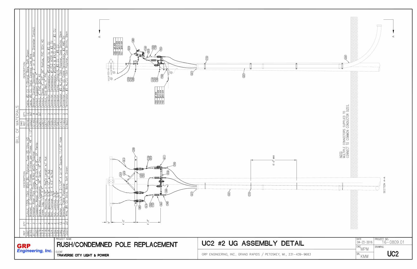
UC2A EA 1
UC2B EA 3
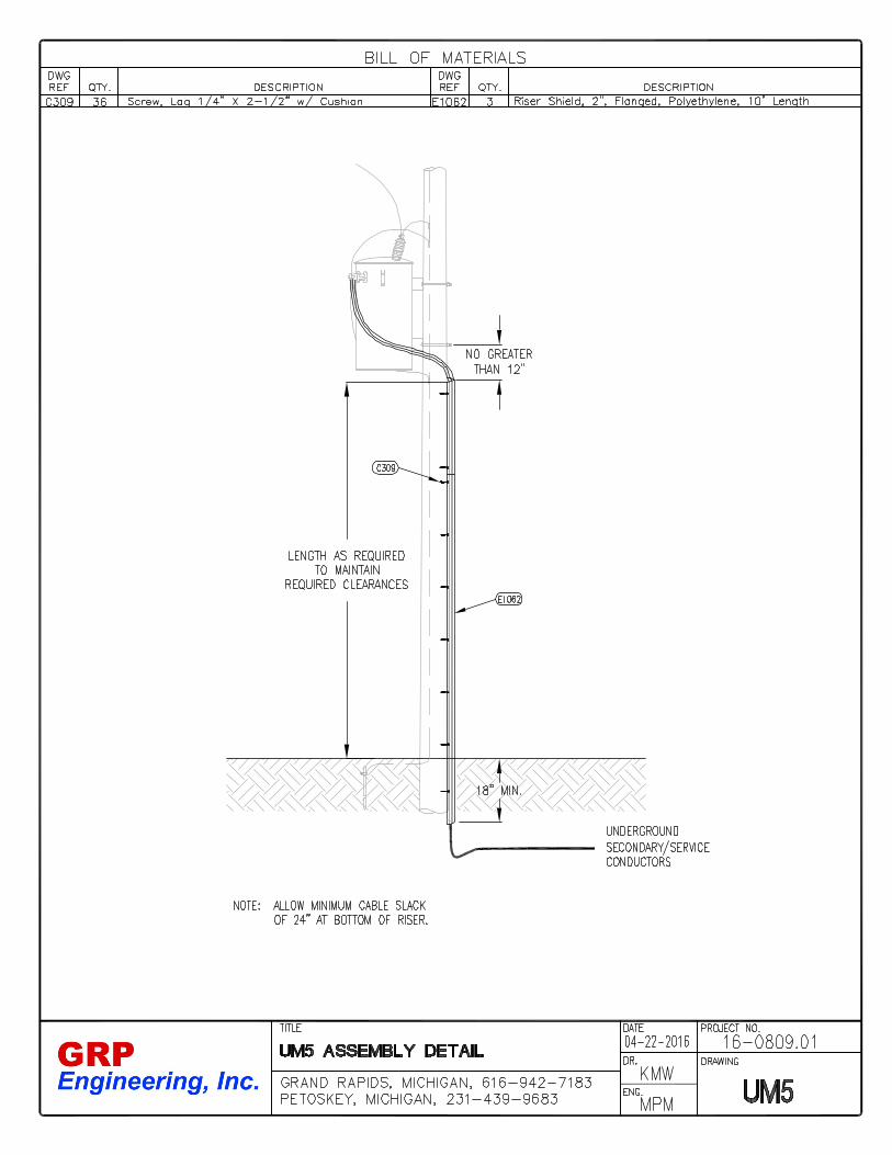
UM5 EA 12
UM6-1B EA 3
#2 7/1 ACSR, "Sparate" LFT 758
#1/0 AL 15kV EPR 1/3rd C.N. LFT 750
Site Removals & Restoration LS 1
Traffic Control & Signage LS 1
Mobilization & Insurance LS 1NEW CONSTRUCTION TOTAL:
16-0809.01 CD21 & CD30 Poles New - 2 5/16/2016

TRAVERSE CITY LIGHT & POWERCD21 & CD30 POLE REPLACEMENT
REMOVAL UNIT LIST
UNIT EXTENDEDUNIT ITEM DESCRIPTION UNIT QUANTITY PRICE TOTAL
30 EA 9
35 EA 12
40 EA 9
45 EA 8
50 EA 8
55 EA 2
A1 EA 5
A5 EA 5
A5-3 EA 2
A9-1 EA 3
C1 EA 9
C1-2 EA 2
C7 EA 7
C8 EA 1
HD-T-14 EA 1
E EA 12
E2-3Fi EA 1
E2-3i EA 9
F EA 10
G EA 6
#2 TX LFT 114
3OWS LFT 295
K10 EA 16
K13 EA 25
K14 EA 53
M5-10 EA 3
M5-10S EA 3
M5-14 EA 1
M5-17 EA 2
M5-2 EA 1
M5-4 EA 1
M5-5 EA 6
M5-9 EA 5
M8-15 EA 1
UC2A EA 1
UC2B EA 3
UM5 EA 11
#6 Solid HDCU LFT 698
Cut Pole Top EA 24REMOVAL TOTAL:
16-0809.01 CD21 & CD30 Poles Removal - 4 5/6/2016

TRAVERSE CITY LIGHT & POWERCD21 & CD30 POLE REPLACEMENT
MATERIAL LIST
ITEM OWNER ITEM SUGGESTED SUGGESTEDNO. QUANTITY FURNISHED DESCRIPTION MANUFACTURER PART #
A-661 26 X Cutout, 100A, 15kV, 95kV BIL, Polymer, Type XS Extra HD MacLean SC15HG110-C-DB-010 46 X Insulator, Pin, Polymer, 15kV, F-Neck, ANSI 55-4 Hendrix HPI-55-4B-024 125 X Insulator, Spool, Polymer, 3" X 3 1/8", 5/8" Pin, 3,000#, ANSI 53-2 Hendrix HPI-53-2B-031 3 X Wire Holder, Nylon, 5/16" X 2-1/4" Lag Screw, 7/8" X 13/16" Slot Chance 2070138B-041 14 X Guard, Guy Guard, 8' Yellow, PVC, Helical Pigtail Wrap MacLean J5518B-051 25 X Insulator, Guy Strain, Porcelain, 1/2", 12,000#, ANSI 54-2 MacLean L-504B-126 5 X Insulator, Guy Strain, Fiberglass, Clevis-Clevis Roller, 54", 21,000# Flagg GCC21-54RB-160 6 X Standoff, Cutout, & Arrester, Fiberglass, Three Hole Cloverleaf Chance 1SBM18CLHB-165 4 X Bracket, 0° Extension, Three-Phase, 3-Holes per Phase, 48" x 13" MacLean G3MA014813DDBB-250 34 X Suspension, Polymer, 15kV, SML 15,000#, Clevis-Eye, Type PDI-15 Ohio Brass 401015-0215B-702 11 X Arrester, Heavy-Duty Distribution Class, 8.4kV MCOV, Polymer, Crossarm Mount MacLean ZHP010-0C00100B-711 12 X Arrester, Riser Pole Class, 8.4kV MCOV, Polymer MacLean ZRP010-0000100B-853 23 X Guard, Bushing Animal Guard Salisbury 21116C-004 125 X Bracket, Spool, 3" Spool, 5/8" Pin MacLean J1300C-018 2 X Anchor Shackle, 5/8" Chance 5801C-025 7 X Pin, Pole Top, 20", 1" Thread Chance 2199C-027 9 X Pin, Crossarm, Steel, 5/8" X 10 3/4", 1" Thread MacLean J203ZC-030 30 X Pin, Crossarm, Saddle-Type, 1" Thread MacLean J3322ZC-038 36 X Pole Eye Plate, 4-5", 21,000# MacLean PEP-66-45C-050 31 X Clevis, Thimble, Dead-End, 20,000# MacLean CT-88C-103 10 X Clamp, Dead-End Shoe, #8 HDCU - #1/0 HDCU, 8,000# Anderson 80500-2000C-1038 7 X Crossarm, Composite, Dead End, 3-5/8" X 4-5/8" X 8', 10,000# Pupi DA2500-096E2-B72C-104 12 X Clamp, Straight Line Dead-End, Bronze, #6 HDCU - #4/0 HDCU, 8,000# Anderson BDE-46-NC-228 100 X Grip, Guy Dead-End, 10M Alumoweld Preformed AWDE-4116C-260 19 X Crossarm, Wood, 3-3/4" X 4-3/4" X 8', DF, Penta, REA Spec, WQC, Type 03 BrooksC-261 2 X Crossarm, Wood, 3-3/4" X 4-3/4" X 10', Penta, REA Spec, WQC, Type 05 BrooksC-279 14 X Brace, Wood Crossarm, 38" Span, 18" Drop Alumaform AF626C-280 13 X Brace, Wood Crossarm, 60" Span, 18" Drop Alumaform RA6018C-314 159 X Screw, Lag 1/2" X 4" Chance 508754C-317_6 24 X Bolt, Machine, 1/2" X 6" w/Nut Chance 8706C-318_10 22 X Bolt, Machine, 5/8" X 10" w/Nut Chance 8810C-318_12 267 X Bolt, Machine, 5/8" X 12" w/Nut Chance 8812C-318_14 154 X Bolt, Machine, 5/8" X 14" w/Nut Chance 8814C-318_16 14 X Bolt, Machine, 5/8" X 16" w/Nut Chance 8816C-318_5 20 X Bolt, Machine, 5/8" X 5" w/Nut Chance 8805C-319_12 40 X Bolt, Machine, 3/4" X 12" w/Nut Chance 8912C-319_14 32 X Bolt, Machine, 3/4" X 14" w/Nut Chance 8914C-324_4.5 14 X Bolt, Carriage, 3/8" X 4.5" w/Nut Chance 863412C-324_7 14 X Bolt, Carriage, 3/8" X 7" w/Nut Chance 8637C-328_24 3 X Bolt, Double Arming, 5/8" X 24" w/Nuts Chance 8874C-335_12 20 X Bolt, Oval Eye, 5/8" X 12" w/ Nut Chance 29962C-352 14 X Nut, Locknut, 3/8" Chance 3510
16-0809.01 Pole Replacement Material List - 1 5/16/2016

ITEM OWNER ITEM SUGGESTED SUGGESTEDNO. QUANTITY FURNISHED DESCRIPTION MANUFACTURER PART #
C-353 50 X Nut, Locknut, 1/2" Chance 3511C-354 389 X Nut, Locknut, 5/8" Chance 3512C-355 72 X Nut, Locknut, 3/4" Chance 3513C-364 21 X Nut, Eye, 5/8" Chance 6502C-377 26 X Washer, Round 1-3/8" Dia., 9/16" Hole Hubbell PS6803C-382 409 X Washer, 2-1/4" X 2-1/4" X 3/16" Square, 11/16" Hole Hubbell 6813C-385 43 X Washer, 3" X 3" X 1/4" Square Curved Washer, 11/16" Hole Chance 682312C-390_C 72 X Washer, Cast, 4" X 4" X 1/4" Square Curved Washer, 13/16" Hole Chance GCW41C-440 12 X Bracket, Cable Positioner Alumaform CS-820C-461 3 X Bracket, Hendrix Tangent W/MC-2 Messenger Clamp, 14" Offset Hendrix BM-14C-465 3 X Bracket, Hendrix Antisway, 14" Hendrix BAS-14FC-479 3 X Bracket, Hendrix Tangent Stirrup Hendrix TS-1C-546 2 X Pre-Formed Ties, Wraplock, #2 ACSR, F-Neck, ANSI 55-4 Preformed WTF-0206C-563 21 X Pre-Formed Ties, Wraplock, #336.4 ACSR 18/1, F-Neck, ANSI 55-4 Preformed WTF-0121C-634 1 X Double Side Tie, #2 ACSR, C/F-Neck, ANSI 55-4 Preformed DBST-1102C-654_E 3 X Spool Tie, EZ-Wrap, #2 ACSR, ANSI 53-2 Preformed EZSP-4374C-661_E 7 X Spool Tie, EZ-Wrap, #366.4 ACSR, ANSI 53-2 Preformed EZSP-4380C-696 13 X Grip, Service, Dead End, #6 TX Neutral Preformed SG-4500C-698 58 X Grip, Service, Dead End, #4 TX Neutral Preformed SG-4502C-700 22 X Grip, Service, Dead End, #2 TX Neutral Preformed SG-4504C-705 1 X Grip, Service, Dead End, #4/0 TX Neutral Preformed SG-4509C-852 8 X Clamp, Straight Line Dead-End, Side Opening, #2 - #336.4 ACSR, 9,000# MacLean HDSO-70D-001 1545 X Wire, #6 CU Solid, Bare, Soft Drawn SouthwireD-016 255 X Cable, #2 CU 7-Strand, Bare, Soft Drawn SouthwireD-052 460 X Wire, Covered Line, #6 CU, Solid Southwire 6CSPS S ###D-207 758 X Cable, #2 7/1 ACSR, "Sparate" SouthwireD-332 332 X Cable, Triplex, (2) #2 7-Strand AL 600V & (1) #2 6/1 ACSR, "Conch" Southwire ConchD-357 150 X Cable, UD Triplex, (2) #1/0 & (1) #2 AL, USE-2 600V, "Brenau" Southwire BrenauD-461 750 X Cable, Concentric Neutral, #1/0 AL 133% EPR 15kV, 33% Neutral OkoniteD-666 1705 X Cable, Guy Strand, 10M Alumoweld AlumoweldE-001 27 X Ground Rod, 5/8" X 8' Copper Clad MacLean J5328E-050 27 X Clamp, Ground Rod, Bronze, 5/8" Blackburn JAB58HE-091 6 X Clamp, Cable - Tank Lug, #8-#2/0, Bronze Anderson GTCS-34AE-097 1255 X Staples, Zinc Plated, Diamond Point, Down Lead Chance 7511E-145 92 X Bracket, Conduit Standoff, 2" or 5" Max Diameter Conduit Sherman & Reilly CRB-U-975E-155 32 X Conduit Support Strap Kit, 4" Alumaform STK-4E-254 36 X Conduit, 2" PVC SCH 40, 10' Length CarlonE-257 12 X Conduit, 4" PVC SCH 40, 10' Length CarlonE-357 4 X Elbow, 4", 90°, 36" Radius, Plain End, PVC SCH 40 Carlon UA9FNE-674 12 X End Bell, 2" PVC Carlon E997JE-677 4 X End Bell, 4" PVC Carlon E997NF-024 14 X Connector, Compression, #2,4,6 ACSR to #2,4,6 ACSR or #2,4,6 CU Blackburn WR159F-025 9 X Connector, Compression, #1/0,2 ACSR to #2,4,6 ACSR or #2,4,6 CU Blackburn WR189F-027 6 X Connector, Compression, #2/0,1/0 ACSR to #2/0,1/0 ACSR or #2/0,#1/0 CU Blackburn WR279F-028 2 X Connector, Compression, #4/0,3/0 ACSR to #2,4,6 ACSR or #2,4,6 CU Blackburn WR379F-033 3 X Connector, Compression, #477,336,4/0 ACSR to #2/0,1/0,2,4 ACSR or #2/0,1/0,2,4,6CU Blackburn WR815F-059 55 X Connector, Compression, Crimp-It, #6 Sol, #4 Str CU to #6 Sol/Str CU Burndy YC4C6
16-0809.01 Pole Replacement Material List - 2 5/16/2016
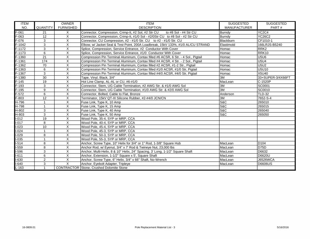
ITEM OWNER ITEM SUGGESTED SUGGESTEDNO. QUANTITY FURNISHED DESCRIPTION MANUFACTURER PART #
F-061 21 X Connector, Compression, Crimp-It, #2 Sol, #2 Str CU to #8 Sol - #4 Str CU Burndy YC2C4F-063 12 X Connector, Compression, Crimp-It, #1/0 Sol - #2/0Str CU to #8 Sol - #2 Str CU Burndy YC26C2F-076 3 X Connector, CU Compression, #2 - #1/0 Str. CU to #2 - #1/0 Str. CU Blackburn CF1010-1F-1042 3 X Elbow, w/ Jacket Seal & Test Point, 200A Loadbreak, 15kV 133%, #1/0 AL/CU STRAND Elastimold 166LRJS-B5240F-1172 3 X Splice, Compression, Service Entrance, #2 Conductor With Cover Homac RRK2F-1173 6 X Splice, Compression, Service Entrance, #1/0 Conductor With Cover Homac RRK10F-1360 21 X Compression Pin Terminal Aluminum, Contax filled #6 ACSR, 6 Str. - 4 Sol., Pigtail Homac U5U6F-1361 174 X Compression Pin Terminal Aluminum, Contax filled #4 ACSR, 4 Str. - 2 Sol., Pigtail Homac U5U4F-1362 70 X Compression Pin Terminal Aluminum, Contax filled #2 ACSR, #1-2 Str., Pigtail Homac U5U2F-1363 6 X Compression Pin Terminal Aluminum, Contax filled #1/0 ACSR, #1/0 Str, Pigtail Homac U5U10F-1367 3 X Compression Pin Terminal Aluminum, Contax filled #4/0 ACSR, #4/0 Str, Pigtail Homac X5U40F-1380 30 X Tape, Vinyl, Black, 3/4" 3M 33+SUPER-3/4X66FTF-145 19 X Hot Line Clamp, AL-AL or CU, #6-#1/0 MacLean C-1520PF-193 3 X Connector, Stem, UG Cable Termination, #2 AWG Str. & #1/0 AWG Sol 3M SC0001F-195 9 X Connector, Stem, UG Cable Termination, #1/0 AWG Str. & #2/0 AWG Sol 3M SC0010F-572 6 X Connector, Bolted, Cable to Flat, Bronze Anderson TLD-32F-803 12 X Terminator, 15kV QT-III Silicone Rubber, #2-#4/0 JCN/CN 3M 7652-S-4H-796 1 X Fuse Link, Type K, 10 Amp S&C 265010H-798 1 X Fuse Link, Type K, 15 Amp S&C 265015H-802 3 X Fuse Link, Type K, 40 Amp S&C 265040H-803 3 X Fuse Link, Type K, 50 Amp S&C 265050I-012 19 X Wood Pole, 35-4, SYP or MRP, CCAI-017 8 X Wood Pole, 40-4, SYP or MRP, CCAI-023 10 X Wood Pole, 45-4, SYP or MRP, CCAI-024 1 X Wood Pole, 45-3, SYP or MRP, CCAI-029 8 X Wood Pole, 50-3, SYP or MRP, CCAI-035 1 X Wood Pole, 55-3, SYP or MRP, CCAI-514 8 X Anchor, Screw Type, 10" Helix for 3/4" or 1" Rod, 1-3/8" Square Hub MacLean D104I-559 8 X Anchor Rod, w/ Eyenut, 3/4" x 7' Rod & Twineye Nut, 23,000 lbs MacLean D75DI-596 3 X Anchor, Multi-Helix, 8 & 10" Helix, 24" Spacing, 3' Long, 1-1/2" Square Shaft MacLean D6632I-611 6 X Anchor, Extension, 1-1/2" Square x 5', Square Shaft MacLean D6620UI-630 2 X Anchor, Screw Type, 6" Helix, 3/4" x 66" Shaft, No-Wrench MacLean J6526WCAI-640 3 X Anchor, Eyebolt Adapter, Tripleye MacLean D6606USL-163 1 CONTRACTOR Stone, Crushed Dolomite Stone
16-0809.01 Pole Replacement Material List - 3 5/16/2016

CD21 & CD30 Pole ReplacementLead: CD21& CD30
Traverse City Light & Power1131 Hastings Street
231.922.4940231.922.4638 FAX
Traverse City, MI 49686
NEW CONSTRUCTION STAKING SHEET
Petoskey459 Bay Street
Petoskey, MI 49770231.439.9683
FAX 231.439.9698
ConductorQty Size Type
4 #6 Solid HDCU
AreaCounty:
Township:Section:
Grand Traverse
10
Town:
Range:
T 27 NR 11 W
Traverse CityMunicipality/City:
Voltage: 7.96/13.8kV
Sheet 1 of 8Work Order #: Project#: 16-0809.01
Guy Anchor Transformer Secondary/Service
Span Conductor Unit
Ground Miscellaneous/Comments
PoleNo.
BackSpan
PoleHeightClass
PriUnits
No. Unit Lead No. Unit
Angle
1 50-3#23063
A1 1 Transfer 3OWS1 Transfer #4 TX1 Transfer #1/0
USE
M2-11 UM5Transfer 1Ø #6 CU SolidCharter22.0'AT&T21.0'
3 K14
2 50-3#23064
A5 G9
Transfer G25DB240
1 Transfer 3OWS3 Transfer #4 TX1 Transfer #4/0
TX
M2-11 UM5M5-10STransfer 1Ø #6 CU SolidCharter21.0'AT&T19.5'
4 K14
3 40-4#23065
1 Transfer 3OWS2 Transfer #4 TX1 Transfer #1/0
USE
UM5Transfer Yard LightCharter20.5'AT&T19.0'
4 K14
4 35-4#28101
3 Transfer #4 TX1 Transfer #6 TX
Charter23.0'AT&T21.5'Satellite dish attached to pole.TCL&P to coordinate removal.
2 K14
5 50-3#23034
C1-2 2 Transfer #6 DX M2-11 Transfer 3Ø #336.4 ACSRCharter24.0'AT&T22.5' & 21.0'
2 K14
6 35-4#23199
4 Transfer #4 TX M2-11 Transfer Yard LightCharter19.5'AT&T18.0'
2 K14
Span Total Designed: 04/11/2016 Revised: As Built: Printed: 05/16/2016 9:02:05AM
Copyright © 2016 GRP Engineering, Inc.

CD21 & CD30 Pole ReplacementLead: CD21& CD30
Traverse City Light & Power1131 Hastings Street
231.922.4940231.922.4638 FAX
Traverse City, MI 49686
NEW CONSTRUCTION STAKING SHEET
Petoskey459 Bay Street
Petoskey, MI 49770231.439.9683
FAX 231.439.9698
ConductorQty Size Type
4 #6 Solid HDCU
AreaCounty:
Township:Section:
Grand Traverse
10
Town:
Range:
T 27 NR 11 W
Traverse CityMunicipality/City:
Voltage: 7.96/13.8kV
Sheet 2 of 8Work Order #: Project#: 16-0809.01
Guy Anchor Transformer Secondary/Service
Span Conductor Unit
Ground Miscellaneous/Comments
PoleNo.
BackSpan
PoleHeightClass
PriUnits
No. Unit Lead No. Unit
Angle
7 35-4#22985
1 12E1-3i1 E2-3i
1 F1-3S 1 Transfer #2 QX1 Transfer #1/0
USE QX
UM5Charter19.0'AT&T18.0'Remove and patch asphalt around pole and anchor.
K14
8 45-4#22986
C7A M2-11 UC2B3 __K Fuse3 UM6-1B750 #1/0 AL 15kV EPR 1/3rd C.N.Transfer 3Ø #6 CU SolidCharter19.5'AT&T18.0'Review extending conduit instead of replacing cable
9 35-4#23235
3 Transfer #4 TX Charter22.0'AT&T21.0' & 19.5'
K14
10 50-3#22802
C1-2C7AA5-3
2 Transfer 3OWS1 Transfer 1OWS
Raise OWS 2.0'
M2-11 M5-5M5-1010K FuseTransfer 1Ø #6 CU SolidTransfer 3Ø #336.4 ACSRTransfer 3Ø #2 HDCUCharter23.0'
6 K14K10
11 50-3#23239
C1-2 1 Transfer 1OWS M2-11 Transfer 3Ø #336.4 ACSRCharter23.0'
K14
Span Total Designed: 04/11/2016 Revised: As Built: Printed: 05/16/2016 9:05:12AM
Copyright © 2016 GRP Engineering, Inc.

CD21 & CD30 Pole ReplacementLead: CD21& CD30
Traverse City Light & Power1131 Hastings Street
231.922.4940231.922.4638 FAX
Traverse City, MI 49686
NEW CONSTRUCTION STAKING SHEET
Petoskey459 Bay Street
Petoskey, MI 49770231.439.9683
FAX 231.439.9698
ConductorQty Size Type
4 #6 Solid HDCU
AreaCounty:
Township:Section:
Grand Traverse
10
Town:
Range:
T 27 NR 11 W
Traverse CityMunicipality/City:
Voltage: 7.96/13.8kV
Sheet 3 of 8Work Order #: Project#: 16-0809.01
Guy Anchor Transformer Secondary/Service
Span Conductor Unit
Ground Miscellaneous/Comments
PoleNo.
BackSpan
PoleHeightClass
PriUnits
No. Unit Lead No. Unit
Angle
12 40-4#23135
100 #2 TX70 #2 TX50 #1/0 USE1 UM45-3 22 UM45-3 1/0
UM5Charter20.0'AT&T18.5'
3 K14
13 40-4#23152
C1-2 1 Transfer 3OWS1 Transfer #4 TX1 Transfer #1/0
USE1 Transfer #2 TX
M2-11 UM5Transfer 3Ø #6 CU SolidCharter22.5'AT&T21.5'
4 K14
14 45-4#22953
A1 2 Transfer #2 TX100 #1/0 USE
2 UM45-3 24 UM45-3 1/0
M2-11 2 UM5Transfer 1Ø #6 CU SolidAT&T23.5'
K14
15 50-3#23092
C1-2 M2-11 Transfer 3Ø #336.4 ACSRCharter21.0'
16 50-3#27028
C7AC8-2
1 20E1-3Fi1 20E1-3i1 20E1-3Fi1 E2-3Fi1 15E1-3i
1 TA-2H1 5.0' EXT.1 TA-2H1 5.0' EXT.1 TA-2H1 5.0' EXT.
2 Transfer 2OWS M2-11 4 M5-5Transfer 3Ø #2 ACSR2 Transfer 3Ø #6 CU SolidTransfer Yard Light
2 K10
17 35-4#22754
2 E2-3i 2 Transfer #2 TX1 Transfer #6 DX1 Transfer #1/0
USE
UM5AT&T19.0'
2 K14
18 35-4#18476
1 Transfer #6 DX Transfer Yard LightAT&T22.0' (Drop)
K14
Span Total Designed: 04/11/2016 Revised: As Built: Printed: 05/16/2016 9:05:12AM
Copyright © 2016 GRP Engineering, Inc.

CD21 & CD30 Pole ReplacementLead: CD21& CD30
Traverse City Light & Power1131 Hastings Street
231.922.4940231.922.4638 FAX
Traverse City, MI 49686
NEW CONSTRUCTION STAKING SHEET
Petoskey459 Bay Street
Petoskey, MI 49770231.439.9683
FAX 231.439.9698
ConductorQty Size Type
4 #6 Solid HDCU
AreaCounty:
Township:Section:
Grand Traverse
10
Town:
Range:
T 27 NR 11 W
Traverse CityMunicipality/City:
Voltage: 7.96/13.8kV
Sheet 4 of 8Work Order #: Project#: 16-0809.01
Guy Anchor Transformer Secondary/Service
Span Conductor Unit
Ground Miscellaneous/Comments
PoleNo.
BackSpan
PoleHeightClass
PriUnits
No. Unit Lead No. Unit
Angle
19 45-4#23513
A1 G9
Transfer G25DB240
1 Transfer 3OWS4 Transfer #4 TX
M2-11 M5-10S246 #2 7/1 ACSR, "Sparate"AT&T22.5', 21.5', 20.5', 22.5' (Drop)Charter23.5'
4 K14
19-1 45-4A2A5
1 Transfer #4 TX1 Transfer 3OWS
M2-11 120 #2 7/1 ACSR, "Sparate"Charter23.5'AT&T22.5', 21.5' & 20.5'
3 K14
19-2 45-4A1 3 Transfer #4 TX
1 Transfer 3OWSM2-11 190 #2 7/1 ACSR, "Sparate"
Transfer Yard LightCharter22.0'AT&T21.0', 20.0' & 19.0'
4 K14
20 45-4#23511
A5 1 E2-3Fi G9
Transfer G25DB240
1 Transfer 3OWS4 Transfer #4 TX
M2-11 M5-10S202 #2 7/1 ACSR, "Sparate"Charter22.5'AT&T21.5', 20.5' & 19.5'
4 K14
20-1 40-41 15E1-3i 1 F1-3S 2 Transfer #4 TX
1 Transfer 3OWSCharter23.0'AT&T21.0' & 20.0'
4 K14
21 35-4#27949
1 12E1-3i 1 F1-3S 1 Transfer #2 TX1 Transfer #4 TX
Charter20.0'
2 K14
22 35-4#27950
3 Transfer #2 TX70 #2 TX55 #2 TX
Charter20.5'
3 K14
Span Total Designed: 04/11/2016 Revised: As Built: Printed: 05/16/2016 9:05:12AM
Copyright © 2016 GRP Engineering, Inc.

CD21 & CD30 Pole ReplacementLead: CD21& CD30
Traverse City Light & Power1131 Hastings Street
231.922.4940231.922.4638 FAX
Traverse City, MI 49686
NEW CONSTRUCTION STAKING SHEET
Petoskey459 Bay Street
Petoskey, MI 49770231.439.9683
FAX 231.439.9698
ConductorQty Size Type
4 #6 Solid HDCU
AreaCounty:
Township:Section:
Grand Traverse
10
Town:
Range:
T 27 NR 11 W
Traverse CityMunicipality/City:
Voltage: 7.96/13.8kV
Sheet 5 of 8Work Order #: Project#: 16-0809.01
Guy Anchor Transformer Secondary/Service
Span Conductor Unit
Ground Miscellaneous/Comments
PoleNo.
BackSpan
PoleHeightClass
PriUnits
No. Unit Lead No. Unit
Angle
23 35-4#23314
1 E2-3i AT&T23.0'TM-101Rake Pole 1.0' South
24 35-4#23443
1 15E1-3i 1 F1-3S 1 Transfer #4 TX1 Transfer #2 TX
Charter22.0' (Lower 1.0')AT&T21.0'
2 K14
25 35-4#23496
2 Transfer #2 TX 2 K14
26 35-4#22675
2 Transfer #4 TX1 Transfer #6 DX
2 K14
27 45-4#22674
HD-T-14C1-2
M2-11HD Transfer 3Ø #336.4 ACSRTransfer 3Ø #336.4 HendrixCharter27.0'AT&T26.0'
28 35-4#22687
1 Transfer #6 DX Transfer Street LightTransfer Ped Signal
K14
29 45-4#23601
C1-2 1 Transfer 1OWS M2-11 Transfer 3Ø #6 CU SolidTransfer Street LightCharter23.5'AT&T22.0' & 21.0'
K14
30 35-4#23593
1 Transfer #2 TX AT&T20.0'
K14
Span Total Designed: 04/11/2016 Revised: As Built: Printed: 05/16/2016 9:05:12AM
Copyright © 2016 GRP Engineering, Inc.

CD21 & CD30 Pole ReplacementLead: CD21& CD30
Traverse City Light & Power1131 Hastings Street
231.922.4940231.922.4638 FAX
Traverse City, MI 49686
NEW CONSTRUCTION STAKING SHEET
Petoskey459 Bay Street
Petoskey, MI 49770231.439.9683
FAX 231.439.9698
ConductorQty Size Type
4 #6 Solid HDCU
AreaCounty:
Township:Section:
Grand Traverse
10
Town:
Range:
T 27 NR 11 W
Traverse CityMunicipality/City:
Voltage: 7.96/13.8kV
Sheet 6 of 8Work Order #: Project#: 16-0809.01
Guy Anchor Transformer Secondary/Service
Span Conductor Unit
Ground Miscellaneous/Comments
PoleNo.
BackSpan
PoleHeightClass
PriUnits
No. Unit Lead No. Unit
Angle
31 40-4#23549
A1 37 #2 TX1 Transfer 3OWS3 Transfer #4 TX1 Transfer #2 TX
M2-11 Transfer 1Ø #6 CU SolidCharter24.0'AT&T22.0' & 21.0'
4 K14
32 35-4#23460
2 12E1-3i 2 F4-1S 2 Transfer 3OWS2 Transfer #4 TX1 Transfer #1/0
USE
UM5AT&T21.0'
3 K14
33 35-4#23625
1 12E1-3i 1 F1-3S 2 Transfer #2 TX Charter22.0'AT&T21.0' (Drops)
2 K14
34 35-4#23452
1 Transfer 3OWS1 Transfer #2 TX
4 K14
35 EX 35-4#22621
Pole Already Replaced
36 35-4#29309
1 12E1-3i 1 F1-3S 3 Transfer #4 TX Charter21.5'AT&T20.5'
3 K14
37 EX 50-3#23533
CE Pole
EX C1-2CEA9-1
G9
Transfer G25DB240
5 Transfer #4 TX1 Transfer #1/0
USE
M2-11 UM5M5-10STransfer 1Ø #6 CU SolidCharter20.5'AT&T19.5'CE to replace pole
4 K14
Span Total Designed: 04/11/2016 Revised: As Built: Printed: 05/16/2016 9:05:12AM
Copyright © 2016 GRP Engineering, Inc.
CD21 & CD30 Pole ReplacementLead: CD21& CD30
Traverse City Light & Power1131 Hastings Street
231.922.4940231.922.4638 FAX
Traverse City, MI 49686
NEW CONSTRUCTION STAKING SHEET
Petoskey459 Bay Street
Petoskey, MI 49770231.439.9683
FAX 231.439.9698
ConductorQty Size Type
4 #6 Solid HDCU
AreaCounty:
Township:Section:
Grand Traverse
10
Town:
Range:
T 27 NR 11 W
Traverse CityMunicipality/City:
Voltage: 7.96/13.8kV
Sheet 7 of 8Work Order #: Project#: 16-0809.01
Guy Anchor Transformer Secondary/Service
Span Conductor Unit
Ground Miscellaneous/Comments
PoleNo.
BackSpan
PoleHeightClass
PriUnits
No. Unit Lead No. Unit
Angle
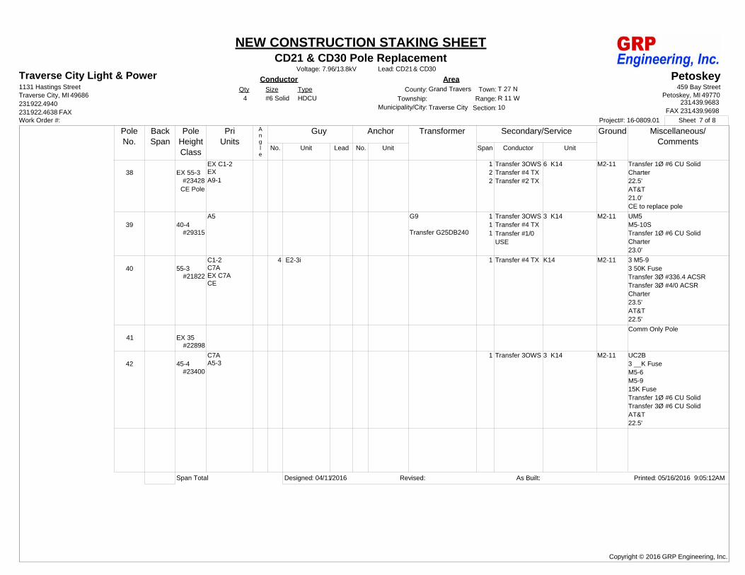
38 EX 55-3#23428
CE Pole
EX C1-2EXA9-1
1 Transfer 3OWS2 Transfer #4 TX2 Transfer #2 TX
M2-11 Transfer 1Ø #6 CU SolidCharter22.5'AT&T21.0'CE to replace pole
6 K14
39 40-4#29315
A5 G9
Transfer G25DB240
1 Transfer 3OWS1 Transfer #4 TX1 Transfer #1/0
USE
M2-11 UM5M5-10STransfer 1Ø #6 CU SolidCharter23.0'
3 K14
40 55-3#21822
C1-2C7AEX C7ACE
4 E2-3i 1 Transfer #4 TX M2-11 3 M5-93 50K FuseTransfer 3Ø #336.4 ACSRTransfer 3Ø #4/0 ACSRCharter23.5'AT&T22.5'
K14
41 EX 35#22898
Comm Only Pole
42 45-4#23400
C7AA5-3
1 Transfer 3OWS M2-11 UC2B3 __K FuseM5-6M5-915K FuseTransfer 1Ø #6 CU SolidTransfer 3Ø #6 CU SolidAT&T22.5'
3 K14
Span Total Designed: 04/11/2016 Revised: As Built: Printed: 05/16/2016 9:05:12AM
Copyright © 2016 GRP Engineering, Inc.

CD21 & CD30 Pole ReplacementLead: CD21& CD30
Traverse City Light & Power1131 Hastings Street
231.922.4940231.922.4638 FAX
Traverse City, MI 49686
NEW CONSTRUCTION STAKING SHEET
Petoskey459 Bay Street
Petoskey, MI 49770231.439.9683
FAX 231.439.9698
ConductorQty Size Type
4 #6 Solid HDCU
AreaCounty:
Township:Section:
Grand Traverse
10
Town:
Range:
T 27 NR 11 W
Traverse CityMunicipality/City:
Voltage: 7.96/13.8kV
Sheet 8 of 8Work Order #: Project#: 16-0809.01
Guy Anchor Transformer Secondary/Service
Span Conductor Unit
Ground Miscellaneous/Comments
PoleNo.
BackSpan
PoleHeightClass
PriUnits
No. Unit Lead No. Unit
Angle
43 45-4#23359
C7A 1 15E1-3i 1 F1-3S M2-11 UC2A3 __K FuseTransfer 3Ø #6 CU SolidCharter24.0'
44 45-3#23686
2 HD-T-14C1-2
1 Transfer #2 TX M2-11 M8-15Transfer 900kVAR Capacitor Bank3 40K FuseTransfer 3Ø #1/0 ACSR2 Transfer 3Ø #336.4 HendrixTransfer 3Ø #336.4 ACSRAT&T21.0' & 22.0'
K14
45 35-4#19759
2 Transfer #6 DX 2 Transfer Yard LightK14
46 40-4#23698
A5 1 15E1-3i 1 F1-3S G9
Transfer G25DB240
2 Transfer #4 TX1 Transfer #6 DX
M2-11 M5-10STransfer 1Ø #6 CU Solid2 Transfer Flood Light
2 K14
47 40-4Set 80'
Deep
C1-2 1 Transfer #2 TX4 Transfer #4 TX
M2-11 Transfer 3Ø #6 CU Solid2 K14
48 50-3C7A 1 E2-3Fi UC2B
3 __K FuseTransfer 3Ø #6A CWC
Span Total Designed: 04/11/2016 Revised: As Built: Printed: 05/16/2016 9:05:12AM
Copyright © 2016 GRP Engineering, Inc.
CD21 & CD30 Pole ReplacementLead: CD21& CD30
Traverse City Light & Power1131 Hastings Street
231.922.4940231.922.4638 FAX
Traverse City, MI 49686
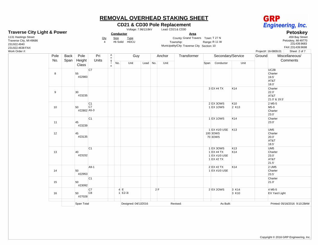
REMOVAL OVERHEAD STAKING SHEET
Petoskey459 Bay Street
Petoskey, MI 49770231.439.9683
FAX 231.439.9698
ConductorQty Size Type
4 #6 Solid HDCU
AreaCounty:
Township:Section:
Grand Traverse
10
Town:
Range:
T 27 NR 11 W
Traverse CityMunicipality/City:
Voltage: 7.96/13.8kV
Sheet 1 of 7Work Order #: Project#: 16-0809.01
Guy Anchor Transformer Secondary/Service
Span Conductor Unit
Ground Miscellaneous/Comments
PoleNo.
BackSpan
PoleHeightClass
PriUnits
No. Unit Lead No. Unit
Angle
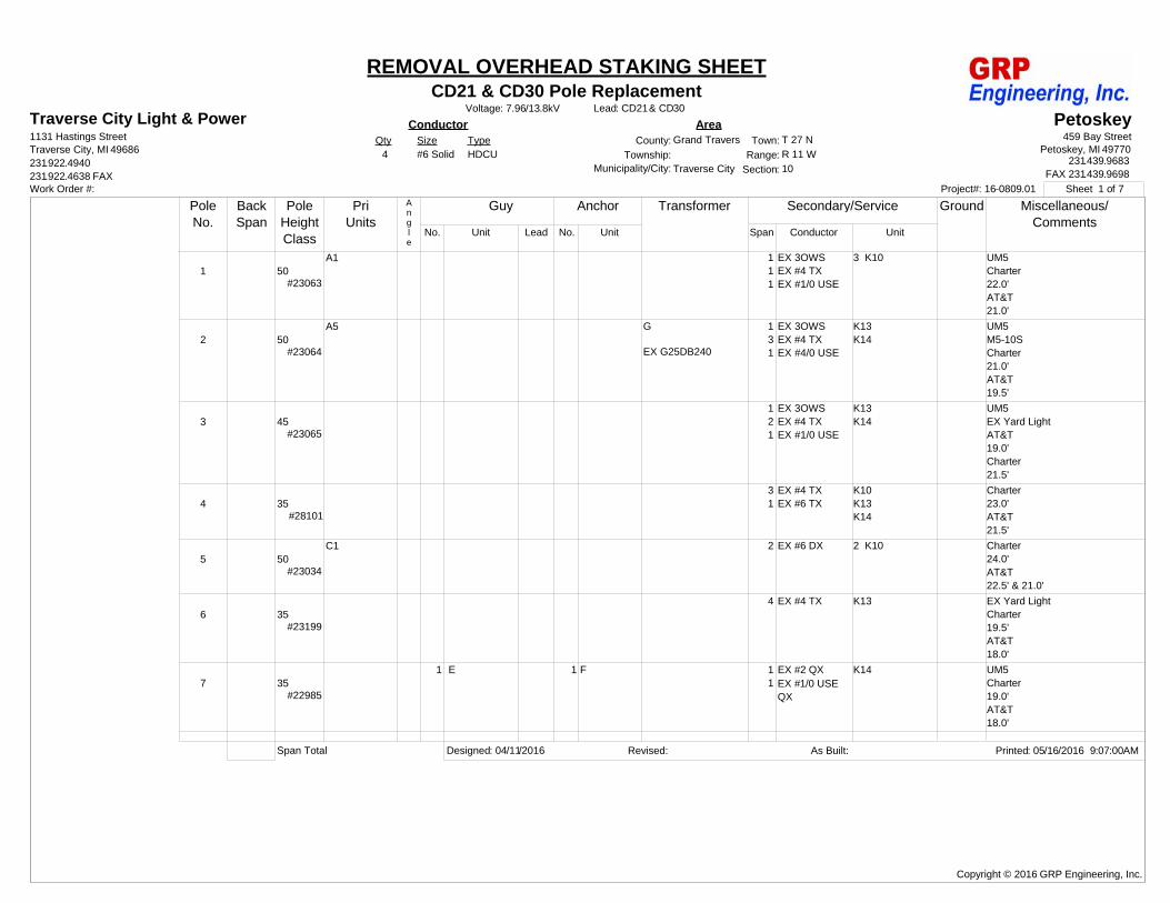
1 50#23063
A1 1 EX 3OWS1 EX #4 TX1 EX #1/0 USE
UM5Charter22.0'AT&T21.0'
3 K10
2 50#23064
A5 G
EX G25DB240
1 EX 3OWS3 EX #4 TX1 EX #4/0 USE
UM5M5-10SCharter21.0'AT&T19.5'
K13K14
3 45#23065
1 EX 3OWS2 EX #4 TX1 EX #1/0 USE
UM5EX Yard LightAT&T19.0'Charter21.5'
K13K14
4 35#28101
3 EX #4 TX1 EX #6 TX
Charter23.0'AT&T21.5'
K10K13K14
5 50#23034
C1 2 EX #6 DX Charter24.0'AT&T22.5' & 21.0'
2 K10
6 35#23199
4 EX #4 TX EX Yard LightCharter19.5'AT&T18.0'
K13
7 35#22985
1 E 1 F 1 EX #2 QX1 EX #1/0 USE
QX
UM5Charter19.0'AT&T18.0'
K14
Span Total Designed: 04/11/2016 Revised: As Built: Printed: 05/16/2016 9:07:00AM
Copyright © 2016 GRP Engineering, Inc.
CD21 & CD30 Pole ReplacementLead: CD21& CD30
Traverse City Light & Power1131 Hastings Street
231.922.4940231.922.4638 FAX
Traverse City, MI 49686
REMOVAL OVERHEAD STAKING SHEET
Petoskey459 Bay Street
Petoskey, MI 49770231.439.9683
FAX 231.439.9698
ConductorQty Size Type
4 #6 Solid HDCU
AreaCounty:
Township:Section:
Grand Traverse
10
Town:
Range:
T 27 NR 11 W
Traverse CityMunicipality/City:
Voltage: 7.96/13.8kV
Sheet 2 of 7Work Order #: Project#: 16-0809.01
Guy Anchor Transformer Secondary/Service
Span Conductor Unit
Ground Miscellaneous/Comments
PoleNo.
BackSpan
PoleHeightClass
PriUnits
No. Unit Lead No. Unit
Angle
8 55#22983
C7 UC2BCharter19.5'AT&T18.0'
9 30#23235
3 EX #4 TX Charter22.0'AT&T21.0' & 19.5'
K14
10 50#22802
C1C7A5-3
2 EX 3OWS1 EX 1OWS
2 M5-5M5-9Charter23.0'
K102 K13
11 45#23239
C1 1 EX 1OWS Charter23.0'
K14
12 45#23135
1 EX #1/0 USE100 3OWS70 3OWS
UM5Charter20.0'AT&T18.5'
K13
13 40#23152
C1 1 EX 3OWS1 EX #4 TX1 EX #1/0 USE1 EX #2 TX
UM5Charter23.0'AT&T21.5'
K13K14
14 50#22953
A9-1 2 EX #2 TX1 EX #1/0 USE
2 UM5Charter23.5'
K14
15 50#23092
C1 Charter21.0'
16 50#27028
C7C8
4 E1 E2-3i
2 F 2 EX 2OWS 4 M5-5EX Yard Light
3 K143 K10
Span Total Designed: 04/11/2016 Revised: As Built: Printed: 05/16/2016 9:10:28AM
Copyright © 2016 GRP Engineering, Inc.
CD21 & CD30 Pole ReplacementLead: CD21& CD30
Traverse City Light & Power1131 Hastings Street
231.922.4940231.922.4638 FAX
Traverse City, MI 49686
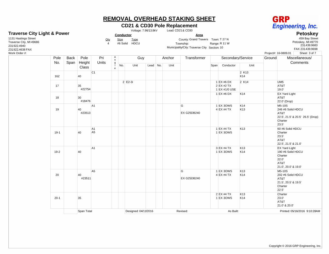
REMOVAL OVERHEAD STAKING SHEET
Petoskey459 Bay Street
Petoskey, MI 49770231.439.9683
FAX 231.439.9698
ConductorQty Size Type
4 #6 Solid HDCU
AreaCounty:
Township:Section:
Grand Traverse
10
Town:
Range:
T 27 NR 11 W
Traverse CityMunicipality/City:
Voltage: 7.96/13.8kV
Sheet 3 of 7Work Order #: Project#: 16-0809.01
Guy Anchor Transformer Secondary/Service
Span Conductor Unit
Ground Miscellaneous/Comments
PoleNo.
BackSpan
PoleHeightClass
PriUnits
No. Unit Lead No. Unit
Angle
16Z 40C1 2 K13
K14
17 35#22754
2 E2-3i 1 EX #6 DX2 EX #2 TX1 EX #1/0 USE
UM5AT&T19.0'
2 K14
18 30#18476
1 EX #6 DX EX Yard LightAT&T22.0' (Drop)
K14
19 40#23513
A1 G
EX G25DB240
1 EX 3OWS4 EX #4 TX
M5-10S246 #6 Solid HDCUAT&T22.5', 21.5' & 20.5' 26.5' (Drop)Charter23.5'
K14K13
19-1 40A1A5
1 EX #4 TX1 EX 3OWS
60 #6 Solid HDCUCharter23.5'AT&T22.5', 21.5' & 21.0'
K13
19-2 40A1 3 EX #4 TX
1 EX 3OWSEX Yard Light190 #6 Solid HDCUCharter22.0'AT&T21.0', 20.0' & 19.0'
K13K14
20 40#23511
A5 G
EX G25DB240
1 EX 3OWS4 EX #4 TX
M5-10S202 #6 Solid HDCUAT&T21.5', 20.5' & 19.5'Charter22.5'
K13K14
20-1 352 EX #4 TX1 EX 3OWS
Charter23.0'AT&T21.0' & 20.0'
K13K14
Span Total Designed: 04/11/2016 Revised: As Built: Printed: 05/16/2016 9:10:28AM
Copyright © 2016 GRP Engineering, Inc.
CD21 & CD30 Pole ReplacementLead: CD21& CD30
Traverse City Light & Power1131 Hastings Street
231.922.4940231.922.4638 FAX
Traverse City, MI 49686
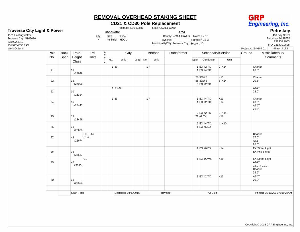
REMOVAL OVERHEAD STAKING SHEET
Petoskey459 Bay Street
Petoskey, MI 49770231.439.9683
FAX 231.439.9698
ConductorQty Size Type
4 #6 Solid HDCU
AreaCounty:
Township:Section:
Grand Traverse
10
Town:
Range:
T 27 NR 11 W
Traverse CityMunicipality/City:
Voltage: 7.96/13.8kV
Sheet 4 of 7Work Order #: Project#: 16-0809.01
Guy Anchor Transformer Secondary/Service
Span Conductor Unit
Ground Miscellaneous/Comments
PoleNo.
BackSpan
PoleHeightClass
PriUnits
No. Unit Lead No. Unit
Angle
21 35#27949
1 E 1 F 1 EX #2 TX1 EX #4 TX
Charter20.0'
2 K14
22 35#27950
70 3OWS55 3OWS3 EX #2 TX
Charter20.5'
K133 K14
23 30#23314
1 E2-3i AT&T23.0'
24 35#23443
1 E 1 F 1 EX #4 TX1 EX #2 TX
Charter23.0'AT&T21.5'
K13K14
25 35#23496
2 EX #2 TX77 #2 TX
2 K14K10
26 30#22675
2 EX #4 TX1 EX #6 DX
4 K10
27 45#22674
HD-T-14C1-2
Charter27.0'AT&T26.0'
28 35#22687
1 EX #6 DX EX Street LightEX Ped Signal
K14
29 45#23601
C1 1 EX 1OWS EX Street LightAT&T22.0' & 21.0'Charter23.5'
K10
30 30#23593
1 EX #2 TX AT&T20.0'
K13
Span Total Designed: 04/11/2016 Revised: As Built: Printed: 05/16/2016 9:10:28AM
Copyright © 2016 GRP Engineering, Inc.

CD21 & CD30 Pole ReplacementLead: CD21& CD30
Traverse City Light & Power1131 Hastings Street
231.922.4940231.922.4638 FAX
Traverse City, MI 49686
REMOVAL OVERHEAD STAKING SHEET
Petoskey459 Bay Street
Petoskey, MI 49770231.439.9683
FAX 231.439.9698
ConductorQty Size Type
4 #6 Solid HDCU
AreaCounty:
Township:Section:
Grand Traverse
10
Town:
Range:
T 27 NR 11 W
Traverse CityMunicipality/City:
Voltage: 7.96/13.8kV
Sheet 5 of 7Work Order #: Project#: 16-0809.01
Guy Anchor Transformer Secondary/Service
Span Conductor Unit
Ground Miscellaneous/Comments
PoleNo.
BackSpan
PoleHeightClass
PriUnits
No. Unit Lead No. Unit
Angle
31 40#23549
A1 1 EX 3OWS3 EX #4 TX1 EX #2 TX
37 #2 TX
Charter24.0'AT&T22.0' & 21.0'
2 K13K14
32 30#23460
2 E 2 F 2 EX 3OWS2 EX #4 TX1 EX #1/0 USE
UM5AT&T21.0'
2 K13
33 35#23625
2 EX #2 TX Charter22.0'AT&T21.0'
2 K14
34 30#23452
1 EX 3OWS1 EX #2 TX
K13K14
35 EX 35-4#22621
Pole Already Replaced
36 30#29309
1 E 1 F 3 EX #4 TX Charter21.5'AT&T20.5'
3 K14
37 EX 50#23533; CE Pole
EX C1CEA9-1
G
EX G25DB240
5 EX #4 TX1 EX #1/0 USE
M5-10Charter20.5'AT&T19.0'CE to replace pole
4 K14
38 EX 55#23428; CE Pole
EX C1CEA9-1
1 EX 3OWS2 EX #4 TX2 EX #2 TX
Charter22.5'AT&T21.0'CE to replace pole
K133 K14
Span Total Designed: 04/11/2016 Revised: As Built: Printed: 05/16/2016 9:10:28AM
Copyright © 2016 GRP Engineering, Inc.
CD21 & CD30 Pole ReplacementLead: CD21& CD30
Traverse City Light & Power1131 Hastings Street
231.922.4940231.922.4638 FAX
Traverse City, MI 49686
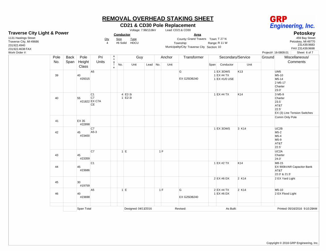
REMOVAL OVERHEAD STAKING SHEET
Petoskey459 Bay Street
Petoskey, MI 49770231.439.9683
FAX 231.439.9698
ConductorQty Size Type
4 #6 Solid HDCU
AreaCounty:
Township:Section:
Grand Traverse
10
Town:
Range:
T 27 NR 11 W
Traverse CityMunicipality/City:
Voltage: 7.96/13.8kV
Sheet 6 of 7Work Order #: Project#: 16-0809.01
Guy Anchor Transformer Secondary/Service
Span Conductor Unit
Ground Miscellaneous/Comments
PoleNo.
BackSpan
PoleHeightClass
PriUnits
No. Unit Lead No. Unit
Angle
39 40#29315
A5 G
EX G25DB240
1 EX 3OWS1 EX #4 TX1 EX #1/0 USE
UM5M5-10M5-142 M5-17Charter23.0'
K13
40 55#21822
C1C7EX C7ACE
4 E2-3i1 E2-3i
1 EX #4 TX 3 M5-9Charter23.5'AT&T22.5'EX (3) Line Tension Switches
K14
41 EX 35#22898
Comm Only Pole
42 45#23400
C7A5-3
1 EX 3OWS UC2BM5-2M5-4M5-9AT&T22.5'
3 K14
43 45#23359
C7 1 E 1 F UC2ACharter24.0'
44 45#23686
C1 1 EX #2 TX M8-15EX 900kVAR Capacitor BankAT&T22.0' & 21.5'
K14
45 30#19759
2 EX #6 DX 2 EX Yard Light2 K14
46 40#23698
A5 1 E 1 F G
EX G25DB240
2 EX #4 TX1 EX #6 DX
M5-102 EX Flood Light
2 K14
Span Total Designed: 04/11/2016 Revised: As Built: Printed: 05/16/2016 9:10:28AM
Copyright © 2016 GRP Engineering, Inc.

CD21 & CD30 Pole ReplacementLead: CD21& CD30
Traverse City Light & Power1131 Hastings Street
231.922.4940231.922.4638 FAX
Traverse City, MI 49686
REMOVAL OVERHEAD STAKING SHEET
Petoskey459 Bay Street
Petoskey, MI 49770231.439.9683
FAX 231.439.9698
ConductorQty Size Type
4 #6 Solid HDCU
AreaCounty:
Township:Section:
Grand Traverse
10
Town:
Range:
T 27 NR 11 W
Traverse CityMunicipality/City:
Voltage: 7.96/13.8kV
Sheet 7 of 7Work Order #: Project#: 16-0809.01
Guy Anchor Transformer Secondary/Service
Span Conductor Unit
Ground Miscellaneous/Comments
PoleNo.
BackSpan
PoleHeightClass
PriUnits
No. Unit Lead No. Unit
Angle
47 35C1-2 1 EX #2 TX
4 EX #4 TX2 K14
48 50C7 1 E2-3Fi UC2B
Span Total Designed: 04/11/2016 Revised: As Built: Printed: 05/16/2016 9:10:28AM
Copyright © 2016 GRP Engineering, Inc.