Traveling Block -...
23
Traveling Block Operation and Maintenance Manual Model: TB5001002 Serial Number: 128 COSCO Shipyard Energy Drilling – N491 PO 49112E001769 SO 2385246
Transcript of Traveling Block -...
Traveling Block
Operation and Maintenance
Manual
Model: TB5001002 Serial Number: 128
COSCO Shipyard Energy Drilling – N491
PO 49112E001769 SO 2385246

Disclaimer
The information in this publication is subject to change without notice.
Improvements in design, engineering, materials, production methods, etc. may necessitate changes to the product and may result in inconsistencies between the numeric values, figures, and descriptions in this publication and the physical equipment. Cameron reserves the right to make any and all changes deemed necessary.
Although the author and publisher have made every effort to ensure that the information in this publication was correct prior to release, the author and publisher do not assume and hereby disclaim any liability to any party for any loss, damage, or disruption caused by errors or omissions, whether such errors or omissions result from negligence, accident, or any other cause.
Copyright
© 2012 Cameron. All Rights Reserved.
This document contains material protected under International and Federal Copyright Laws and Treaties. Any unauthorized reprint or use of this material is prohibited.
No part of this document may be reproduced or transmitted in any form or by any means, electronic or mechanical, including photocopying, recording, or by any information storage and retrieval system, without express written permission from Cameron.
Trademarks
The following are registered trademarks or trademarks of Cameron, and/or its subsidiaries and/or affiliates in the USA and other countries:
LEWCO™
All other brand names, product names or trademarks belong to their respective holders.
Published By
Cameron Drilling Systems 6401 W. Sam Houston Parkway N. Houston, TX 77041 Tel: 713.983.4700, Tel: 832-782-6500
Document No. DS-TB-OMM
Revision History
Revision Level
Date Description of Change
00 05/12 Initial Release
01 12/12 Corrected labels on the diagram in the Assembly and Parts List section. Updated graphics in the Assembly and Disassembly sections.
LEWCO™ Traveling Block Operation and Maintenance Manual
Page 1 of 20
Table of Contents
Conventions ............................................................................................................................................. 2
Contact Information ................................................................................................................................. 2
Warranty and Liability Information ............................................................................................................. 2
Introduction ............................................................................................................................................. 3
Warnings, Responsibilities, and Procedures ................................................................................................ 3
Owner and Operator Responsibilities ........................................................................................................................... 4
Accessories and Safety Equipment ............................................................................................................................... 4
General Safety Provisions ............................................................................................................................................. 4
Traveling Block Assembly and Parts List ...................................................................................................... 5
Traveling Block Parts List .............................................................................................................................................. 6
Specifications ........................................................................................................................................... 7
Installation ............................................................................................................................................... 8
Pre-Installation Checklist .............................................................................................................................................. 8
Reeving the Drill Line ................................................................................................................................................... 8
Hook or Top Drive Bell ................................................................................................................................................. 8
Operation ................................................................................................................................................. 9
Sheave Bearing Lubrication .......................................................................................................................................... 9
Maintenance .......................................................................................................................................... 10
Daily Maintenance ..................................................................................................................................................... 10
Weekly Maintenance ................................................................................................................................................. 10
Quarterly Maintenance .............................................................................................................................................. 10
Semiannual Maintenance........................................................................................................................................... 11
Five Year Maintenance .............................................................................................................................................. 12
Disassembly ............................................................................................................................................................... 13
Assembly ................................................................................................................................................................... 16
Storage and Preservation ......................................................................................................................... 20
LEWCO™ Traveling Block Operation and Maintenance Manual
Page 2 of 20
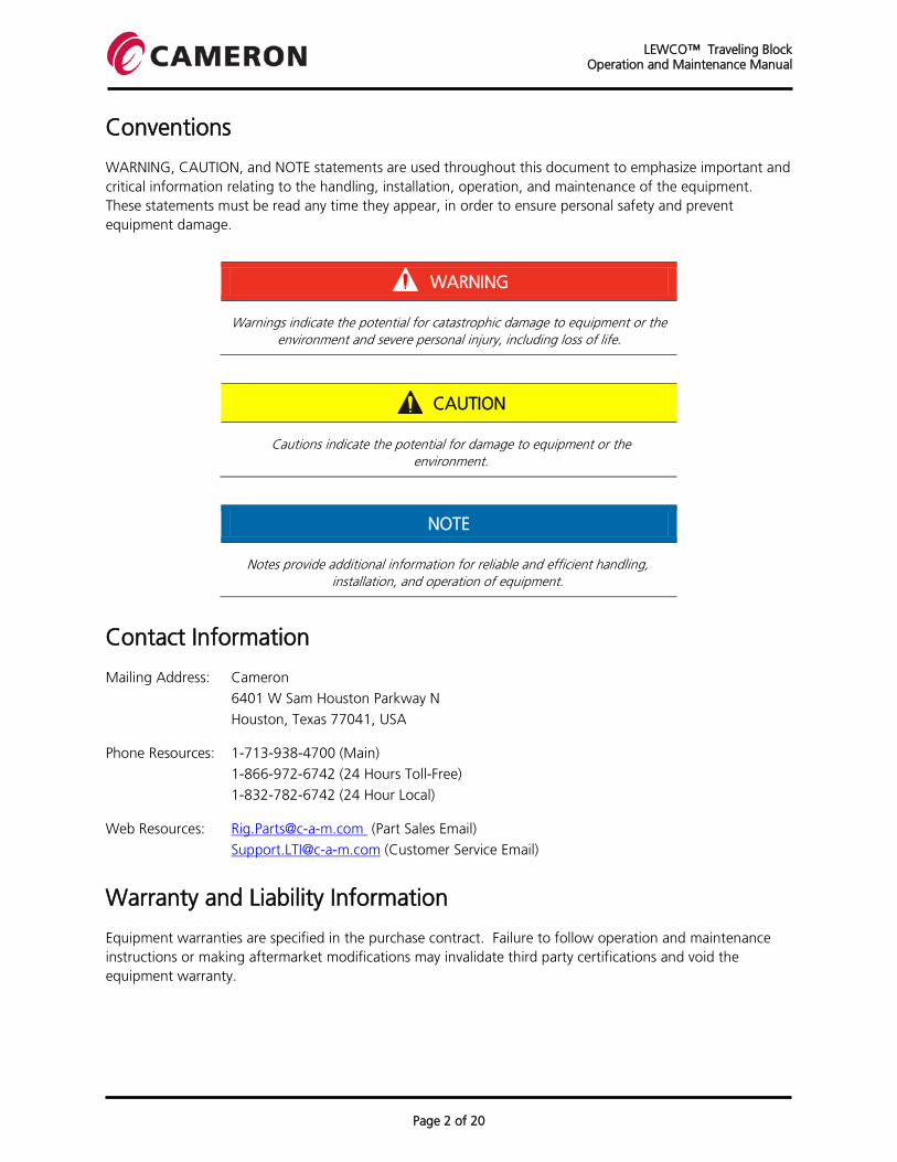
Conventions
WARNING, CAUTION, and NOTE statements are used throughout this document to emphasize important and critical information relating to the handling, installation, operation, and maintenance of the equipment. These statements must be read any time they appear, in order to ensure personal safety and prevent equipment damage.
WARNING
Warnings indicate the potential for catastrophic damage to equipment or the environment and severe personal injury, including loss of life.
CAUTION
Cautions indicate the potential for damage to equipment or the environment.
NOTE
Notes provide additional information for reliable and efficient handling, installation, and operation of equipment.
Contact Information
Mailing Address: Cameron
6401 W Sam Houston Parkway N
Houston, Texas 77041, USA
Phone Resources: 1-713-938-4700 (Main)
1-866-972-6742 (24 Hours Toll-Free)
1-832-782-6742 (24 Hour Local)
Web Resources: [email protected] (Part Sales Email)
[email protected] (Customer Service Email)
Warranty and Liability Information
Equipment warranties are specified in the purchase contract. Failure to follow operation and maintenance instructions or making aftermarket modifications may invalidate third party certifications and void the equipment warranty.

LEWCO™ Traveling Block Operation and Maintenance Manual
Page 3 of 20
Introduction
This manual is published as a general guide for the operation and maintenance of the LEWCO™ Traveling Block, manufactured by Cameron. Because of the many factors that may contribute to the proper function or malfunction of this equipment, and not having complete knowledge of each factor or combination of factors on location, all facets of this subject cannot be detailed here. Therefore, the scope of this presentation is confined. When situations are encountered that are not fully encompassed by complete and understandable instructions, the situation should then be referred to personnel at Cameron.
When servicing is necessary, outside of the scope of routine maintenance, it can be most effectively performed if the unit or primary components being serviced are moved from the location of operation to an area of adequate space. Shelter should also be available and readily accessible.
Use sound mechanical practices and proper safety precautions at all times. Ensure personnel are adequately trained and have all updated documentation and/or drawings prior to performing any maintenance on this equipment.
WARNING
Use of inadequately trained or unprepared personnel could result in damage to equipment and serious injury or loss of life to personnel.
Cameron reserves the right to change, discontinue, or modify Traveling Block models at any time without notice and without incurring any obligation. Improvements in design, engineering, materials, production methods, etc. may necessitate changes in the Traveling Block and may result in inconsistencies between this publication and the physical equipment. Cameron reserves the right to make any and all changes deemed necessary.
NOTE
The drawings, diagrams, and photographs shown in this publication may be of similar equipment and may not appear exactly like the equipment
supplied.
Warnings, Responsibilities, and Procedures
WARNING
Carefully read and understand the operation and maintenance instructions. Failure to follow these instructions may result in equipment damage and
severe personal injury, including loss of life.
LEWCO™ Traveling Block Operation and Maintenance Manual
Page 4 of 20
Owner and Operator Responsibilities
It is the buyer’s and operator’s responsibility to obtain proper instruction and to train personnel in the safe operation and maintenance of this equipment. The buyer and operator must obtain instruction in safe operation and maintenance of the motors, controls, and any accessories and safety devices required to operate this equipment safely and to complete the application of this product.
Accessories and Safety Equipment
This product is supplied in accordance with the buyer’s specifications and does not necessarily include all accessories and safety devices required to put this product into operation.
Safety devices such as, but not limited to, rotating equipment guards, chains, cables, and wrenches are available from other suppliers.
WARNING
Never disable guards, safety systems, or switches to equipment for any reason.
General Safety Provisions
Before conducting maintenance or repair operations, the following general safety precautions and provisions should be followed at all times. All provisions or all the possible eventualities of accidents during use cannot be listed here. Proper training, precaution, and good judgment should always be followed when operating, maintaining, or repairing equipment.
1. Wear proper eye protection, such as safety glasses or goggles.
2. Remove jewelry, such as rings, watches, necklaces, etc.
3. Personnel should always wear Personal Protective Equipment (PPE) such as steel toe footwear, hard hat, etc. Ensure PPE clothing is available if the task requires such protection.
4. ALWAYS wear and properly secure a safety harness when working at an elevated level.
5. Turn off and lock-out any electrical power prior to performing any task on electrical equipment.
6. Avoid working with loose tools or components directly above any other people.
7. ALWAYS ensure heavy and/or overhead components being removed or installed are moved and lifted with the proper equipment and the equipment is properly secured.
8. ALWAYS use the appropriate tools. NEVER use a tool for a purpose it is not designed for. NEVER modify any tool.
9. Shut down ALL drilling equipment and disconnect power during maintenance. In order to prevent personal injury during maintenance or inspection, all drilling equipment should be shut down or turned off and the power disconnected. Employ good mechanical practices when making maintenance repairs and adjustments.
LEWCO™ Traveling Block Operation and Maintenance Manual
Page 5 of 20
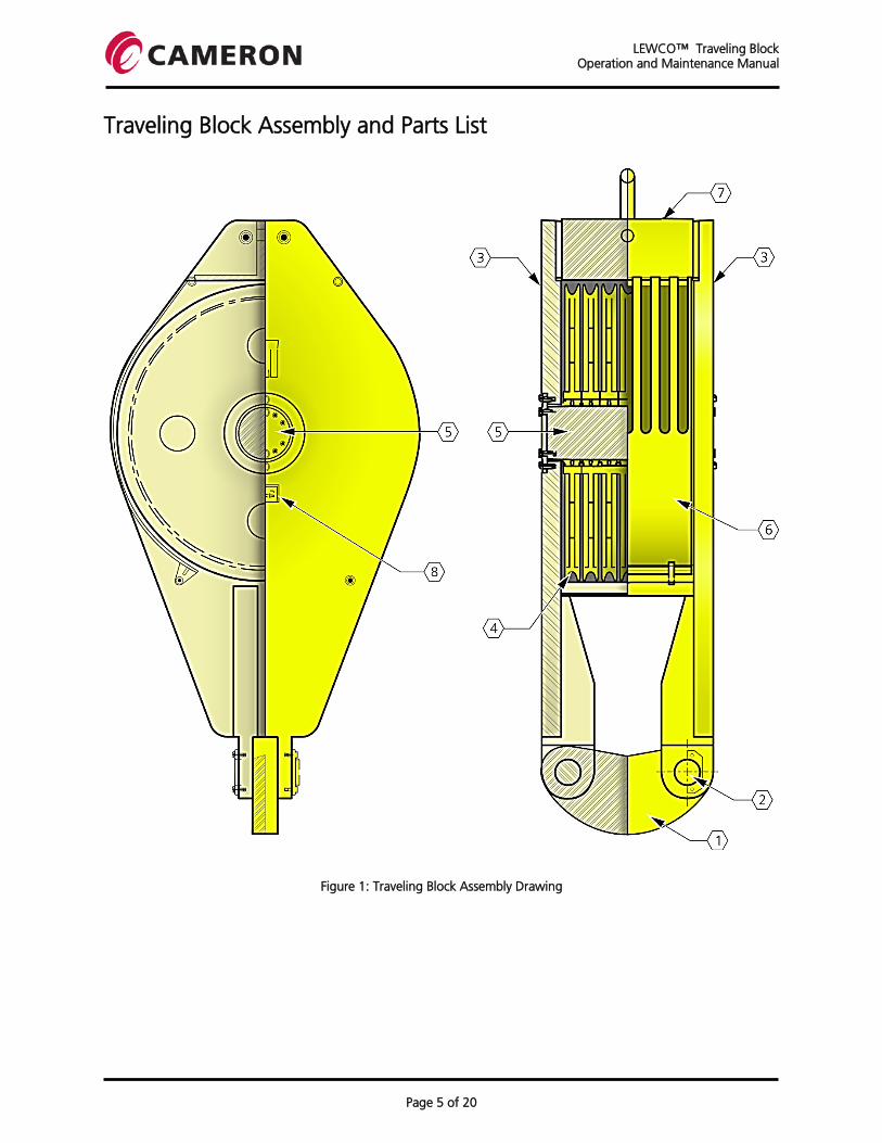
Traveling Block Assembly and Parts List
Figure 1: Traveling Block Assembly Drawing

LEWCO™ Traveling Block Operation and Maintenance Manual
Page 6 of 20
Traveling Block Parts List
1. Becket: The solid steel becket is attached below the side plates and provides a connection for the hook or top drive.
2. Becket Pins: The becket pins are made from heat-treated alloy steel. They attach the becket to brackets that are integral with the side plates.
3. Side Plates: The side plates cover the sides of the block and carry loads from the top to bottom of the block.
4. Sheaves: The sheaves transmit the wire line load to the sheave pin. They operate on sealed tapered roller bearings. The wire line grooves are accurately formed to A.P.I. specifications.
5. Sheave Pin: The sheave pin is made from heat-treated alloy steel and transmits the load from the sheaves to the side plates. It also contains grease fittings and passageways for lubricating the sheave bearings.
6. Sheave Guards: The sheave guards are removable plates constructed to permit easy reeving of the block and provide protection for the sheaves during operation.
7. Hood: The hood is the primary hang off point for suspending the block during installation and maintenance operations.
8. Name Plate: The nameplate bears the model and serial numbers of the block. These numbers are required to correctly identify the block for maintenance purposes.
LEWCO™ Traveling Block Operation and Maintenance Manual
Page 7 of 20
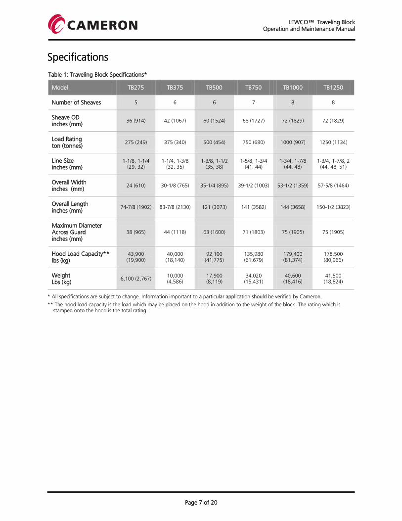
Specifications
Table 1: Traveling Block Specifications*
Model TB275 TB375 TB500 TB750 TB1000 TB1250
Number of Sheaves 5 6 6 7 8 8
Sheave OD inches (mm)
36 (914) 42 (1067) 60 (1524) 68 (1727) 72 (1829) 72 (1829)
Load Rating ton (tonnes)
275 (249) 375 (340) 500 (454) 750 (680) 1000 (907) 1250 (1134)
Line Size inches (mm)
1-1/8, 1-1/4 (29, 32)
1-1/4, 1-3/8 (32, 35)
1-3/8, 1-1/2 (35, 38)
1-5/8, 1-3/4 (41, 44)
1-3/4, 1-7/8 (44, 48)
1-3/4, 1-7/8, 2 (44, 48, 51)
Overall Width inches (mm)
24 (610) 30-1/8 (765) 35-1/4 (895) 39-1/2 (1003) 53-1/2 (1359) 57-5/8 (1464)
Overall Length inches (mm)
74-7/8 (1902) 83-7/8 (2130) 121 (3073) 141 (3582) 144 (3658) 150-1/2 (3823)
Maximum Diameter Across Guard inches (mm)
38 (965) 44 (1118) 63 (1600) 71 (1803) 75 (1905) 75 (1905)
Hood Load Capacity** lbs (kg)
43,900 (19,900)
40,000 (18,140)
92,100 (41,775)
135,980 (61,679)
179,400 (81,374)
178,500 (80,966)
Weight Lbs (kg)
6,100 (2,767) 10,000 (4,586)
17,900 (8,119)
34,020 (15,431)
40,600 (18,416)
41,500 (18,824)
* All specifications are subject to change. Information important to a particular application should be verified by Cameron.
** The hood load capacity is the load which may be placed on the hood in addition to the weight of the block. The rating which is stamped onto the hood is the total rating.
LEWCO™ Traveling Block Operation and Maintenance Manual
Page 8 of 20
Installation
Pre-Installation Checklist
1. Check the nameplate on the block for capacity. Verify that the sum of the block and all anticipated supported loads does not exceed the amount listed on the nameplate.
2. Check the becket pins and lock plates to make sure they are properly installed.
3. Bolt and nuts are properly tightened. Lock nuts in place. Lock wires on drilled head bolts.
4. Measure the sheave groove per API RP 9B. Verify that the drilling line matches the sheave grooves.
Reeving the Drill Line
1. Support the traveling block from the hood shackle.
2. Rotate the traveling block so its sheaves are parallel with the crown block sheaves.
3. Remove the upper sheave guard retaining pins and nuts. Open the sheave guards.
4. Reeve the drilling line per I.A.D.C. Drilling Manual (Chapter M: Wire Rope, Section 2: Care and Handling, Item B: Proper Steps in Stringing Line).
5. Use the Drawworks to hoist the traveling block a few inches.
6. Verify that the drilling line is seated properly in the traveling block and crown block sheave grooves.
7. Close the sheave guards. Replace the upper sheave guard retaining pins and lock nuts.
8. Disconnect the hood shackle from its support.
Hook or Top Drive Bell
1. Support the becket to allow controlled lowering.
2. Screw a lifting eye into the lock plate end of one becket pin.
3. Remove the lock plate from the becket pin.
4. Using the lifting eye of Step 2 remove the becket pin, and lower to the drill floor.
5. Lower the becket until it hangs on the remaining becket pin.
6. Move the hook or top drive bail into a position between the side plate brackets and above the becket pins.
7. Raise the becket to align the hole in the becket with the holes in the side plate bracket.
8. Insert the becket pin from step 4 into the aligned holes.
9. Install the lock plate, torque the bolts and wire the heads.
10. Remove the lifting eye installed in Step 2.
LEWCO™ Traveling Block Operation and Maintenance Manual
Page 9 of 20
Operation
Sheave Bearing Lubrication
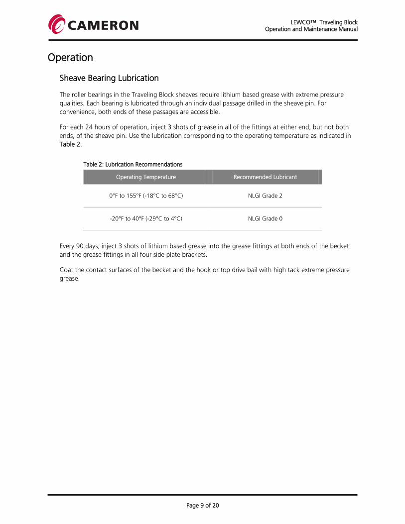
The roller bearings in the Traveling Block sheaves require lithium based grease with extreme pressure qualities. Each bearing is lubricated through an individual passage drilled in the sheave pin. For convenience, both ends of these passages are accessible.
For each 24 hours of operation, inject 3 shots of grease in all of the fittings at either end, but not both ends, of the sheave pin. Use the lubrication corresponding to the operating temperature as indicated in Table 2.
Table 2: Lubrication Recommendations
Operating Temperature Recommended Lubricant
0°F to 155°F (-18°C to 68°C) NLGI Grade 2
-20°F to 40°F (-29°C to 4°C) NLGI Grade 0
Every 90 days, inject 3 shots of lithium based grease into the grease fittings at both ends of the becket and the grease fittings in all four side plate brackets.
Coat the contact surfaces of the becket and the hook or top drive bail with high tack extreme pressure grease.
LEWCO™ Traveling Block Operation and Maintenance Manual
Page 10 of 20
Maintenance
A properly implemented preventive maintenance program will help reduce down time, lower the cost of repairs, and enhance safety. It is strongly recommended that a written log of maintenance activities be kept in a notebook for future reference. The following represents a minimum maintenance program of the Traveling Block assembly. Additional items may need to be added to comply with your safety program, company policies, or local governmental regulations.
Daily Maintenance
1. Lubricate each sheave bearing with 1 to 3 shots of grease before each trip per Table 2.
2. Lubricate the contact surfaces of the becket and the hook or top drive bail.
3. Visually inspect the Traveling Block to make sure of the following:
3.1 The sheave guards are properly secured
3.2 The sheave guards do not show wear from the wire rope
3.3 All bolts and nuts are in place, properly tightened and locked
3.4 Becket pin lock plates are properly secured
3.5 No other dangerous or undesirable conditions are present
Weekly Maintenance
1 . Perform the Daily Maintenance procedure.
2 . Clean off loose paint, scale, dirt, and grease around the sheave pin bore and becket pin bore areas in the side plate brackets.
3 . Visually inspect the sheave and becket pin bore areas for cracks. If cracks are found, remove the Traveling Block from service and perform a 5-year inspection.
Quarterly Maintenance
1 . Perform the Weekly Maintenance procedure.
2 . Lubricate each becket pin with three shots of grease.
3 . Remove accumulated scale, dirt, and grease from the becket.
4 . Lubricate the becket and the hook or top drive bail contact areas.

LEWCO™ Traveling Block Operation and Maintenance Manual
Page 11 of 20
Semiannual Maintenance
1 . Review the logs from previous inspections. Identify repeating problem areas. Disassemble the Traveling Block to determine the extent of damage in these areas and repair as necessary.
2 . Open both sheave guards.
3 . Remove loose paint, scale, dirt, and grease.
4 . Visually inspect the sheave rims for cracks and wear per API RP 9B.
5 . Check the sheaves for excessive run-out, roughness or grinding during rotation.
6 . Perform A.P.I. RP 8B recommended semiannual inspection. If cracks are found remove the Traveling Block from service and perform a 5 year inspection.
7 . Measure the depth of the becket, shown as measurement “Y” in Figure 2. If the depth is less than the dimension indicated in Table 3, replace the becket.
Table 3: Minimum Becket Depth According to Model
Traveling Block Model Minimum Becket Depth (Y)
TB275 10.444"
TB375 12.250"
TB500 13.625"
TB750 16.625"
TB1000 17.688"
TB1250 19.000"
Figure 2: Traveling Block Depth Measurement

LEWCO™ Traveling Block Operation and Maintenance Manual
Page 12 of 20
Five Year Maintenance
1 . Remove the Traveling Block from service and completely disassemble. Refer to the Disassembly section for specific instructions.
2 . Perform API RP 8B recommended five year inspection, including a nondestructive examination of all structural parts. This inspection should include the hood, hood bolts, side plates, sheaves, sheave pin, becket, and becket pins.
3 . If any cracks are found, or if there is any indication of a malfunction of any type (bearing movement, marks on the shaft, etc.) contact Cameron for assistance.
4 . Measure the depth of the becket as shown in Figure 2. If the depth is less than the corresponding dimension in the chart for the capacity of the Traveling Block the becket should be replaced.
5 . Reassembly the Traveling Block according to the instructions in the Assembly section.
LEWCO™ Traveling Block Operation and Maintenance Manual
Page 13 of 20
Disassembly
Use the following instructions for disassembly of the Traveling Block:
1 . Review the General Safety Provisions section.
2 . Place the Traveling Block, with the nameplate facing up, on supports and at least 18" off the floor. Provide support for the sheave pin.
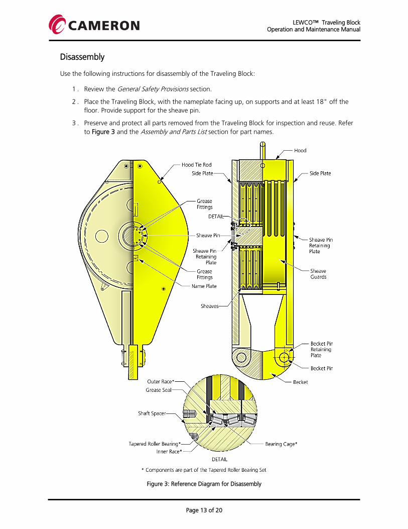
3 . Preserve and protect all parts removed from the Traveling Block for inspection and reuse. Refer to Figure 3 and the Assembly and Parts List section for part names.
Figure 3: Reference Diagram for Disassembly
LEWCO™ Traveling Block Operation and Maintenance Manual
Page 14 of 20
4 . Remove the becket using the following steps:
4.1. Choke a sling around the middle of the becket and hoist it to remove the load from the becket pins.
4.2. Screw a 1" eyebolt into one of the becket pins.
4.3. Remove the two hex head screws from the becket pin retaining plate and remove the becket pin retaining plate.
4.4. Pull the becket pin completely out of the side plate bracket and set aside.
4.5. Repeat Steps 4.1 through 4.4 for the other becket pin.
4.6. Slide the becket sideways until it is free of the side plate brackets and set aside.
5 . Remove the sheave guards using the following steps:
9.1. Attach a sling to the second finger from the top of the sheave guard and the other end of the guard.
9.2. Hoist the sheave guard slightly to remove the load from the sheave guard tie rods.
9.3. Remove the four locknuts from the sheave guard tie rods and remove the sheave guard tie rods.
9.4. Slide the sheave guard sideways until it is free of the side plate and set it aside.
9.5. Repeat Steps 5.1 through 5.4 for the other sheave guard and the bottom guard, if removable.
6 . Remove the side plate using the following steps:
6.1. Screw four 1" eyebolts into the edge of the top side plate if holes are available, otherwise use best rigging practice.
6.2. Attach one leg of a four point lifting device to each eyebolt or rigging.
6.3. Remove the hex head screws from the sheave pin retaining plate and remove the sheave pin retaining plate.
6.4. Remove the two hex bolts, nuts, and flat washers holding the side plate to the hood.
6.5. Hoist the side plate straight up until clear of the sheave pin and set aside.
6.6. If the shaft spacer remains with the side plate, loosen it by gently tapping on the outside edge until it falls from the plate.
7 . Remove the hood using the following steps:
7.1. Attach a sling to the hood shackle.
7.2. Remove the two hex bolts, nuts, and flat washers holding the hood to the side plate.
7.3. Lift the hood from the lower side plate and set aside.
LEWCO™ Traveling Block Operation and Maintenance Manual
Page 15 of 20
8 . Remove the sheaves and sheave bearings using the following steps:
8.1. If the shaft spacer did not remain with the side plate, slide the shaft spacer up and off the end of the sheave pin. Take care not to damage the OD or ID surfaces.
8.2. Set the shaft spacer aside.
8.3. Using a three or four point lifting device, hoist the top sheave off of the sheave pin.
8.4. If the bearing cone and grease seal remain on the sheave pin, lift them up off the sheave pin and reinsert them into the bottom of the sheave bore.
8.5. Set the sheave aside taking care to keep the bearings clean.
8.6. Repeat Steps 8.2 through 8.5 until all of the sheaves have been removed.
9 . Remove the sheave pin using the following steps:
9.1. Screw one or two eyebolts into the top end of the sheave pin.
9.2. Hoist the sheave pin slightly to remove the load from the sheave pin retaining plate.
9.3. From the underside of the side plate, remove the hex head screws holding the sheave pin retaining plate and set the plate aside.
9.4. Hoist the sheave pin above the side plate and set aside. Take care not to damage the OD surface.
9.5. If the shaft spacer did not remain with the side plate, slide the shaft spacer off the end of the sheave pin. Take care not to damage the OD or ID surfaces.
9.6. If the shaft spacer sticks to the side plate, loosen it by gently tapping on the top edge until it falls from the plate. Set the shaft spacer aside.
1 0 . Remove the sheave bearing using the following steps:
10.1. Do not remove the sheave bearings and seals unless these parts are to be replaced with new parts.
10.2. Support the sheave horizontally.
10.3. Pry the upper seal from the sheave bore being careful not to damage the sheave bore surface.
10.4. Remove the upper portion (cone) of the inner bearing assembly.
10.5. Press or use a bronze bar to drive the outer bearing race (cup) downward until the race clears the sheave hub bore. The lower portion (cone) of the inner bearing assembly and the lower seal will fall from the sheave bore as the outer bearing race travels downward.

LEWCO™ Traveling Block Operation and Maintenance Manual
Page 16 of 20
Assembly
Use the following instructions for assembly of the Traveling Block:
1. Review the General Safety Provisions section.
2. Set the side plate without a nameplate on supports at least 18" off the floor. The brackets should be pointing upward to the right.
3. Make sure all unpainted surfaces of all parts are free from dust, dirt, and loose paint and lightly coat them with grease prior to installation.
4. Preserve and protect all parts removed from the traveling block for inspection and reuse. Refer to Figure 4 and the Assembly and Parts List section for part names.
Figure 4: Reference Diagram for Assembly

LEWCO™ Traveling Block Operation and Maintenance Manual
Page 17 of 20
5. Install the sheave pin using the following steps:
5.1. Loosely attach the sheave pin retaining plate to the underside of the side plate with at least two diametrically opposed hex head screws. Allow 1/8" space between the retaining plate and the side plate.
5.2. Slip the shaft spacer into the bore of the side plate until the shaft spacer rests on the sheave pin retaining plate.
5.3. Screw one or two eyebolts into the end of the sheave pin.
5.4. Hoist the sheave pin over the side plate.
5.5. Lower the sheave pin into the bore of the shaft spacer. Orient the sheave pin so the tapped holes are aligned with the holes in the sheave pin retaining plate.
5.6. Lower the sheave pin until the sheave pin rests on the sheave pin retaining plate.
5.7. Loosely attach the sheave pin retaining plate to the sheave pin with at least two head screws. Allow 1/8" clearance between the screw head and the retainer plate.
5.8. If a new sheave pin is being installed or if the grease holes of the old pin have been cleaned, install the grease fittings into both ends of the sheave pin.
5.9. Pump grease into each of the fittings on one end of the sheave pin until grease comes out of the related hole on the side of the pin.
5.10. Pump grease into each of the fittings on the other end of the pin until a solid column of grease comes out of the related hole on the side of the pin.
6. Install the sheave bearing and seals using the following steps:
6.1. Support the sheave horizontally.
6.2. Press or use a bronze bar to drive the outer bearing race (cup) downward into the sheave hub bore until the race is laterally centered in the sheave bore.
6.3. Pack the upper portion (cone) of the inner bearing assembly with lithium-base grease and insert it into the bearing.
6.4. Place the bearing seal on the sheave hub bore with the sealing lips pointed downward (toward the bearing). Tap the bearing seal into the sheave hub bore. The seal must be tight in the sheave hub bore.
6.5. Ensure that the grease seal is inside the face of the bearing inner (cone) assembly.
6.6. Turn the sheave bottom side to top side and repeat Steps 6.3, 6.4 and 6.5.
7. Install the sheaves using the following steps:
7.1. Using a three or four point lifting device, hoist a sheave over the sheave pin.
7.2. Ensure that the bearing cone and grease seal remain on the underside of the sheave.
7.3. Carefully lower the sheave onto the sheave pin until it comes to rest.
7.4. Remove the lifting device from the sheave.
7.5. Repeat Steps 7.1 through 7.4 until all of the sheaves have been placed on the sheave pin.
LEWCO™ Traveling Block Operation and Maintenance Manual
Page 18 of 20
8. Install the hood using the following steps:
8.1. Attach a sling to the hood shackle.
8.2. Hoist the hood and place it on the side plate. Orient the hood so the shackle is on the left side and the flat plates on either end are at the top and bottom.
8.3. Move the hood around until the hood bolt holes line up with their respective holes in the side plate.
8.4. Attach the hood to the side plate with two hex bolts, nuts, and flat washers.
9. Install the side plate using the following steps:
9.1. Screw four 1" eyebolts into the edge of the top side plate if holes are available. If not, use best rigging practice.
9.2. Attach one leg of a four point lifting device to each eyebolt or rigging.
9.3. Orient the side plate so the nameplate is facing up and the brackets point down and to the right.
9.4. Hoist the side plate and position the center hole over the sheave pin.
9.5. Carefully lower the side plate until the sheave pin is fully engaged in the center hole and the side plate rests on the top sheave.
9.6. Slide the shaft spacer over the end of the sheave pin and down between the sheave pin and side plate center-hole.
9.7. Loosely install the sheave pin retaining plate and the hex head retaining screws. Allow 1/8" clearance between the screw head and the retainer plate.
9.8. Attach the hood to the side plate with two hex bolts, nuts, and flat washers.
10. Install the becket using the following steps:
10.1. Choke a sling to the middle of the becket, hoist it, and locate it near the side plate brackets.
10.2. Orient the becket so the holes are horizontal and slide it sideways until it is between the side plate brackets.
10.3. Align one of the becket holes with the holes in the side plate brackets.
10.4. Choke a sling around the middle of one of the becket pins.
10.5. Hoist the becket pin and slide the tapered end into the aligned holes of Step 10.3.
10.6. Place the becket pin retaining plate near the becket pin and continue sliding the becket pin sideways until the retaining plate engages the groove near the end of the becket pin.
10.7. Install two hex head screws through the becket pin retaining plate and into the side plate bracket.
10.8. Repeat Steps 10.4 through 10.7 for the other becket pin.
LEWCO™ Traveling Block Operation and Maintenance Manual
Page 19 of 20
11. Install the sheave guards using the following steps:
11.1. Attach a sling to the second finger from the one edge of the sheave guard.
11.2. Attach a sling to the hinge at the other end of the sheave guard.
11.3. Hoist the sheave guard and orient so the fingers point to the left.
11.4. Slide the sheave guard sideways until it is between the side plates and the guard retainer holes align with the side plate holes.
11.5. Screw one lock nut on the end of a sheave guard tie rod.
11.6. Drop a flat washer into the proper counterbore of the side plate.
11.7. Slide the sheave guard tie rod down through the counterbore and respective holes in the side plates and sheave guard retainer. If the block contains a loose lower sheave guard, the lower sheave guard tie rod must also pass through those retainers.
11.8. Screw a lock nut and flat washer onto the lower end of the sheave guard tie rod.
11.9. Repeat Steps 11.4 through 11.8 at the other end of the sheave guard.
12. Complete the assembly using the following steps:
12.1. Torque each bolt nut or screw in accordance with the bolt torque chart.
12.2. Torque the two hex head screws in each of the becket pin retaining plate and lock wire together.
12.3. Torque the two lock nuts on each sheave guard tie rod. Make sure that the ends of the sheave guard tie rods do not extend more than 1/8" past the face of the side plate.
12.4. Torque the four hex head screws and lock nuts in the hood, two each end.
12.5. Torque the hex head screws attaching each sheave pin retaining plate to the sheave pin and lockwire together.
12.6. Torque the hex head screws attaching each sheave pin retaining plate to the side plate and lockwire together.
LEWCO™ Traveling Block Operation and Maintenance Manual
Page 20 of 20
Storage and Preservation
The packaging of the equipment should not be altered or removed before the equipment is to be commissioned. Disruption of the packaging may result in exposure of the equipment and its components which may cause damage and result in suboptimal operation.
In general, the equipment should not be submerged in water, exposed to excessive vibration, or allowed to collide with other equipment or property during transport or storage. This may cause severe damage to the equipment making it unsuitable for use at the site of commissioning.
A properly preserved Traveling Block will remain in operational condition for many years. The following are general recommendations for Traveling Block storage:
1. The traveling block should be stored indoors, although outside storage is allowable for brief periods.
2. The Traveling Block should be stored off the ground on wooden blocks when kept in outdoor or indoor locations.
3. Do not cover the Traveling Block with plastic because it will hold moisture against the metal parts.
4. Place the Traveling Block so the sheave and becket pins are horizontal and the weight of the traveling block is resting on the edges of the side plates and face of the becket.
Perform the following tasks when the Traveling Block is first put into storage and at regular 90-day intervals:
1. Lubricate each sheave bearing with three shots of grease while rotating at least one full revolution.
2. Inspect all painted surfaces. If corrosion is found, clean the area with emery cloth down to bright metal and coat with a zinc rich primer.
3. Lubricate each becket pin by putting three shots of grease into each of the three grease fittings for each pin (one in the end of the becket and one in each of the associated brackets).
4. Coat all unpainted surfaces with a suitable rust preventative. These surfaces include the sheaves, sheave pin, becket, and becket pins.
For further information or for assistance, contact Cameron. Refer to the Contact Information section.

HSE Policy StatementAt Cameron, we are committed ethically, financially, and personally to a working environment where no one gets hurt, nothing gets harmed.
© 2012 Cameron I LEWCO and OEM are trademarks of Cameron
Cameron
Drilling Systems6401 W Sam Houston Parkway NHouston, TX 77041, USATel: 713.983.4700Tel: 832.782.650024/7 Toll Free: 1.866.972.674224/7 Local: 1.832.782.6742
[email protected]@c-a-m.com
PO Box 1212Houston, TX 77251-1212, USATel: 713.983.2211Fax: 713.983.2611
www.c-a-m.com
Cameron