TRANS/WP.29/GRSG/2003/?? - unece.org€¦ · Web viewNATIONS. E Economic and Social. Council....
51
UNITED NATIONS E Economic and Social Council Distr. GENERAL TRANS/WP.29/GRSG/2005/20 25 July 2005 Original: ENGLISH ENGLISH AND FRENCH ONLY ECONOMIC COMMISSION FOR EUROPE INLAND TRANSPORT COMMITTEE World Forum for Harmonization of Vehicle Regulations (WP.29) Working Party on General Safety Provisions (GRSG) (Eighty-ninth session, 11-14 October 2005, agenda item 1.4.1.) PROPOSAL FOR DRAFT 02 SERIES OF AMENDMENTS TO REGULATION No. 107 (M2 and M3 vehicles) Transmitted by the secretariat Note : The text reproduced below was prepared by the secretariat following the GRSG decision to consolidate the proposals for the draft 02 series of amendments to Regulation No. 107 (TRANS/WP.29/GRSG/67, para. 11). This document is the consolidation of the proposals of documents
Transcript of TRANS/WP.29/GRSG/2003/?? - unece.org€¦ · Web viewNATIONS. E Economic and Social. Council....
UNITEDNATIONS E
Economic and SocialCouncil
Distr.GENERAL
TRANS/WP.29/GRSG/2005/2025 July 2005
Original: ENGLISH ENGLISH AND FRENCH ONLY
ECONOMIC COMMISSION FOR EUROPE
INLAND TRANSPORT COMMITTEE
World Forum for Harmonization of Vehicle Regulations (WP.29)
Working Party on General Safety Provisions (GRSG)(Eighty-ninth session, 11-14 October 2005, agenda item 1.4.1.)
PROPOSAL FOR DRAFT 02 SERIES OF AMENDMENTS TO REGULATION No. 107
(M2 and M3 vehicles)
Transmitted by the secretariat
Note: The text reproduced below was prepared by the secretariat following the GRSG decision to consolidate the proposals for the draft 02 series of amendments to Regulation No. 107 (TRANS/WP.29/GRSG/67, para. 11). This document is the consolidation of the proposals of documents TRANS/WP.29/GRSG/2003/21, TRANS/WP.29/GRSG/67, para. 10, GRSG-87-26, GRSG-88-6 and GRSG-88-26, which it supersedes.
________________Note: This document is distributed to the Experts on General Safety Provisions only.
TRANS/WP.29/GRSG/2005/20page 2
A. PROPOSAL
The list of contents, amend to read:"..................Annex 5 - (Reserved).................Annex 9 - (Reserved).................Annex 12 - Trolleybuses."
The text of the Regulation,
Insert a new paragraph 2.1.8., to read:
"2.1.8. "Trolleybus" means a vehicle, electrically driven by energy from external, overhead contact wires. For the purposes of this Regulation, it also includes such vehicles having an additional internal means of propulsion (dual mode vehicles) or having a means of external guidance (guided trolleybuses)."
Paragraph 2.15.1., amend to read:
"2.15.1. the space extending 300 mm in front of any seat, except where a sideways-facing seat is situated above a wheel arch, in which case this dimension may be reduced to 225 mm (see Annex 4, figure 25)."
Paragraph 2.27., amend to read:
"2.27. "Starting prevention device" means a device which prevents the vehicle being driven away from rest when a door is not fully closed;"
Paragraph 4.2., amend to read:
"4.2. An approval number shall be assigned to each vehicle type approved. Its first two digits (at present 02, corresponding to the 02 series of amendments) shall indicate the series of amendments incorporating the most recent major technical amendment made to the Regulation at the time of issue of the approval. The same Contracting Party may not assign the same number to another vehicle or bodywork type within the meaning of paragraph 2.2."
Paragraph 5.1., amend to read:
"5.1. All vehicles shall comply with the provisions set out in Annex 3 to this Regulation. Bodywork approved separately shall comply with Annex 10. The approval of a vehicle incorporating a bodywork approved in accordance with Annex 10 shall be completed in accordance with that annex."

TRANS/WP.29/GRSG/2005/20page 3
Paragraphs 10.1. to 10.4., amend to read:
"10.1. As from the official date of entry into force of the 02 series of amendments, no Contracting Party applying this Regulation shall refuse to grant ECE approval under this Regulation as amended by the 02 series of amendments.
10.2. No Contracting Party applying this Regulation shall refuse national type approval of a vehicle type approved to the 02 series of amendments to this Regulation.
10.3. As from 12 August 2007, Contracting Parties applying this Regulation shall grant approvals only if the vehicle type to be approved meets the requirements of this Regulation as amended by the 02 series of amendments.
10.4. As from 12 August 2010, Contracting Parties applying this Regulation may refuse first national registration (first entry into service) of a vehicle which does not meet the requirements of the 02 series of amendments to this Regulation."
Insert a new paragraph 10.5., to read:
"10.5. As from the date mentioned in paragraph 10.3., Contracting Parties applying this Regulation shall no longer grant new approvals in accordance with Regulation No. 36 or Regulation No. 52."
Annex 1, Part 1, Appendices 1 and 2, items 5.3. and 5.4., amend to read:
"5.3. Number of passengers (seated and standing):
5.3.1. Total (N): 2/
5.3.2. Upper deck (Na): 1/2/
5.3.3. Lower deck (Nb): 1/2/
5.4. Number of passengers (seated): 2/
5.4.1. Total (A): 2/
5.4.2. Upper deck (Aa): 1/2/
5.4.3. Lower deck (Ab): 1/2/"
Add a new explanatory footnote 2/, to read:
"2/ In the case of an articulated vehicle, specify the number of seats in each rigid section."
TRANS/WP.29/GRSG/2005/20page 4
Annex 1, Part 1, Appendix 1,
Item 5.11.1., for available read applicable.
Items 5.11.2. to 5.11.2.4., should be deleted.
Annex 1, Part 1, Appendix 2,
Item 5.10.1., for available read applicable.
Items 5.10.2. to 5.10.2.4., should be deleted.
Annex 1, Part 1, Appendix 3,
Item 4..1., for available read applicable.
Items 4.2. to 4.4., should be deleted.
Annex 2,
In the example of the approval marks and in the captions below amend the approval number "012439" to read "022439" (5 times, related to Regulation No. 107). [In Model B, the letter "A" shall be deleted]. In addition, in the caption below Models A and C of the approval mark amend the words "01 series of amendments" to read "02 series of amendments". The caption below Model B of the approval mark amend to read as follows (footnote */ not modified):
"... on the dates on which these approvals were granted Regulation No. 107 included the 02 series of amendments and Regulation No. 43 was in its original form."
Annex 3,
Paragraph 7.2.2.2., amend to read:
"7.2.2.2. The surface area S1 available for standing passengers (only in the case of vehicles of Class A, I and II, in which the carriage of standing passengers is allowed) is calculated by deducting from S0:"
Paragraph 7.3.1., amend to read:
"7.3.1. All single-deck Class II and III vehicles shall have superstructures which comply with the requirements of Regulation No. 66."
Paragraph 7.4.2.1., amend to read:
"7.4.2.1. Loads equal to Q (as defined in paragraph 7.4.3.3.1. of Annex 11) shall be placed on each passenger seat (of the upper deck only in the case of double-deck vehicles).
TRANS/WP.29/GRSG/2005/20page 5
If a single deck vehicle is intended for standees or with a crew member who is not seated, the centre of gravity of the loads Q or 75kg representing them, shall be uniformly distributed over the standee or crew area respectively, at a height of 875 mm. If a double deck vehicle is intended to be used with a crew member who is not seated, the centre of gravity of the mass of 75 kg representing the crew member shall be placed in the upper deck gangway at a height of 875 mm.
Where a vehicle is equipped to carry luggage on the roof, a uniformly distributed mass (BX) of not less than that declared by the manufacturer in accordance with paragraph 7.4.3.3.1. of Annex 11, representing such baggage shall be secured to the roof. The other baggage compartments shall not contain any baggage."
Paragraph 7.5.2.3., amend to read:
"7.5.2.3. Every electrical circuit feeding an item of equipment other than the starter, the ignition circuit (positive ignition), the glow-plugs, the engine-stopping device, the charging circuit and the battery earth connection shall include a fuse or a circuit breaker. Circuits feeding low consumption equipment may, however, be protected by a common fuse or a common circuit-breaker, provided that its rated capacity does not exceed 16 A. In the case where electronics are incorporated, these circuits may be protected by protection devices integrated into the electronic components or systems. In such a case, the manufacturer shall give all the relevant technical information at the request of the technical service responsible for conducting the tests."
Paragraph 7.5.4.1., amend to read:
"7.5.4.1. Space shall be provided for the fitting of one or more fire extinguishers, one being near the driver's seat. In vehicles of Class A or B the space shall be not less than 8 dm3 and in Class I, II or III not less than 15 dm3. In the case of a double-deck vehicle, an additional extinguisher space shall be provided on the upper deck."
Paragraph 7.5.5., amend to read:
"7.5.5. Materials
No flammable material shall be permitted within 100 mm of the exhaust system component, any high voltage electrical equipment or any other significant source of heat unless the material is effectively shielded. Where necessary, shielding shall be provided to prevent grease or other flammable materials coming into contact with exhaust system or other significant heat sources. For the purposes of this paragraph, a flammable material is considered to be one which is not designed to withstand the temperatures likely to be encountered in that location."
TRANS/WP.29/GRSG/2005/20page 6
Paragraph 7.6.1.1., amend to read:
"7.6.1.1. The minimum number of doors in a vehicle shall be two, either two service doors or one service door and one emergency door. Every double-deck vehicle shall have two doors on the lower deck (see also paragraph 7.6.2.2). The minimum number of service doors required is as follows:
Number of passengers
Number of service doors
CLASS I & A CLASS II CLASS III & B9 - 45 1 1 146 - 70 2 1 171 - 100 3
(2 in the case of a double-deck vehicle)
2 1
> 100 4 3 1"
Paragraph 7.6.1.4., amend to read:
"7.6.1.4. The minimum number of emergency exits shall be such that the total number of exits in a separate compartment is as follows:
Number of passengers and crew to be accommodated in each compartment or
deck
Minimum total number of exits
1 - 8 29 - 16 317 - 30 431 - 45 546 - 60 661 - 75 776 - 90 891 - 110 9111 - 130 10
>130 11
The number of exits for each separate deck (in the case of a double-deck vehicle) and each separate compartment must be determined separately. Toilet compartments or galleys are not considered to be separate compartments for the purposes of defining the number of emergency exits. Escape hatches can only count as one of the above-mentioned number of emergency exits."
Paragraph 7.6.1.5., amend to read:
"7.6.1.5. Each rigid section of an articulated vehicle shall be treated as a separate vehicle for the purpose of determining the minimum number and the position of exits, except for paragraph 7.6.2.4. Toilet compartments or galleys are not considered to be separate compartments for the purposes of defining the number of
TRANS/WP.29/GRSG/2005/20page 7
emergency exits. A number of passengers shall be determined for each rigid section. The plane, which lies through the geometric centre of the turning section floor, and perpendicular to the longitudinal axis of a vehicle, when it moves straight, shall be considered as the border between sections."
Paragraph 7.6.1.8., amend to read:
"7.6.1.8. If the driver's compartment and any seats adjacent to it are accessible from the main passenger compartment by means of a passageway complying with one of the conditions described in paragraph 7.7.5.1.1., no external exit is required from the driver's compartment."
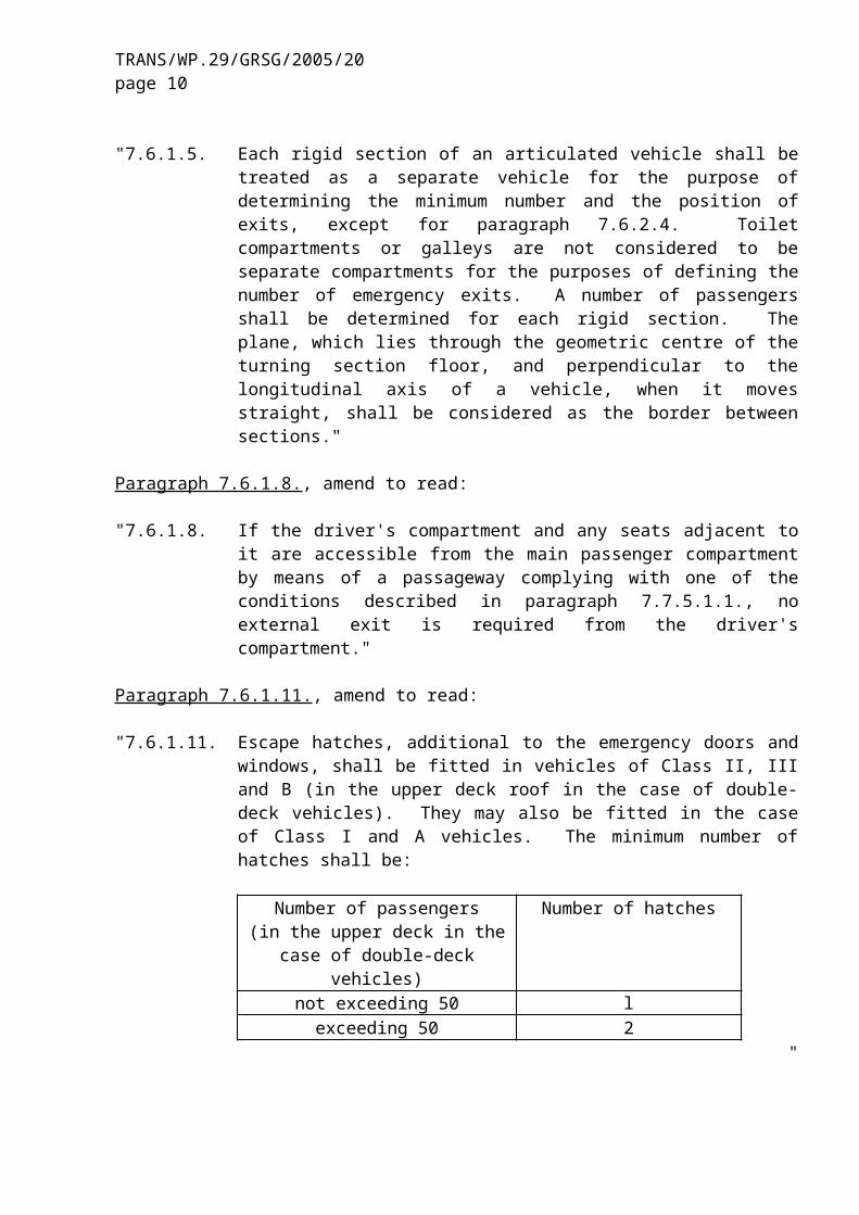
Paragraph 7.6.1.11., amend to read:
"7.6.1.11. Escape hatches, additional to the emergency doors and windows, shall be fitted in vehicles of Class II, III and B (in the upper deck roof in the case of double-deck vehicles). They may also be fitted in the case of Class I and A vehicles. The minimum number of hatches shall be:
Number of passengers (in the upper deck in the case of
double-deck vehicles)
Number of hatches
not exceeding 50 lexceeding 50 2
"
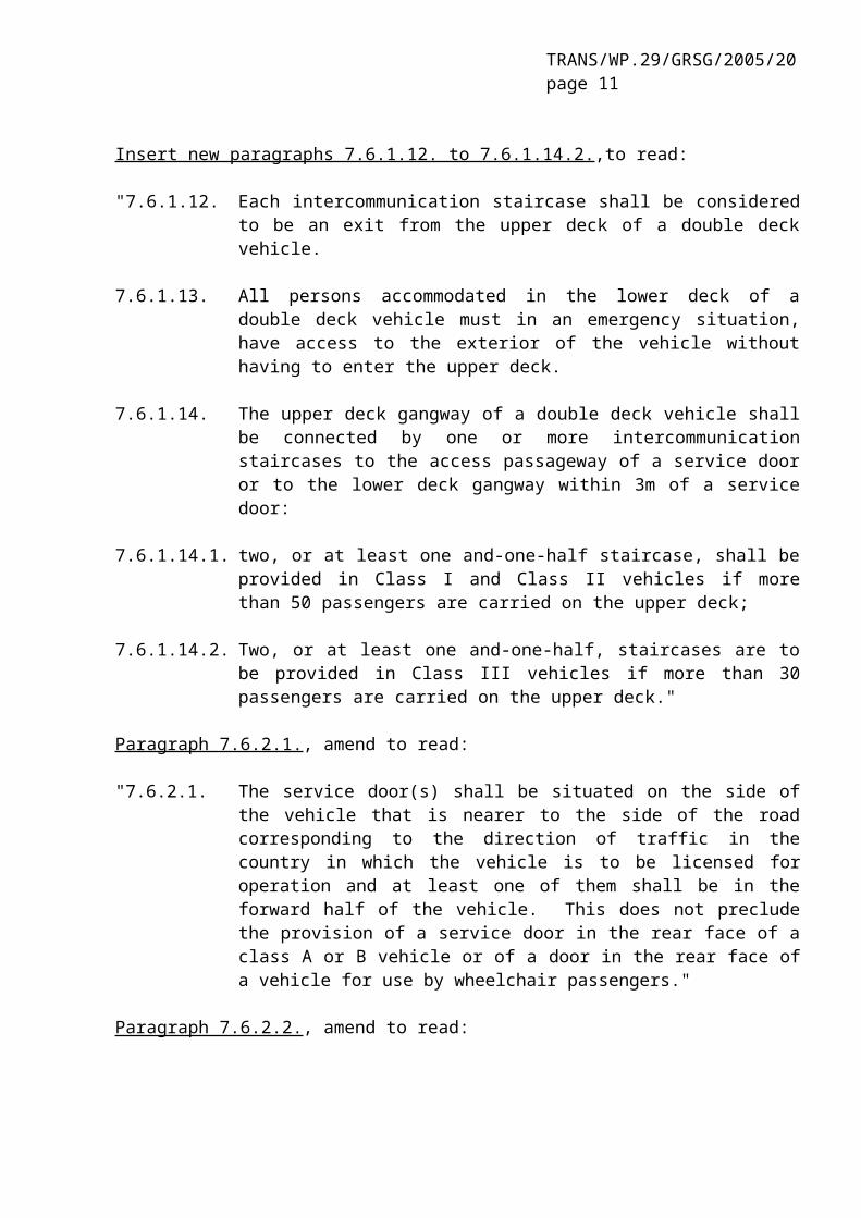
Insert new paragraphs 7.6.1.12. to 7.6.1.14.2.,to read:
"7.6.1.12. Each intercommunication staircase shall be considered to be an exit from the upper deck of a double deck vehicle.
7.6.1.13. All persons accommodated in the lower deck of a double deck vehicle must in an emergency situation, have access to the exterior of the vehicle without having to enter the upper deck.
7.6.1.14. The upper deck gangway of a double deck vehicle shall be connected by one or more intercommunication staircases to the access passageway of a service door or to the lower deck gangway within 3m of a service door:
7.6.1.14.1. two, or at least one and-one-half staircase, shall be provided in Class I and Class II vehicles if more than 50 passengers are carried on the upper deck;
7.6.1.14.2. Two, or at least one and-one-half, staircases are to be provided in Class III vehicles if more than 30 passengers are carried on the upper deck."
TRANS/WP.29/GRSG/2005/20page 8
Paragraph 7.6.2.1., amend to read:
"7.6.2.1. The service door(s) shall be situated on the side of the vehicle that is nearer to the side of the road corresponding to the direction of traffic in the country in which the vehicle is to be licensed for operation and at least one of them shall be in the forward half of the vehicle. This does not preclude the provision of a service door in the rear face of a class A or B vehicle or of a door in the rear face of a vehicle for use by wheelchair passengers."
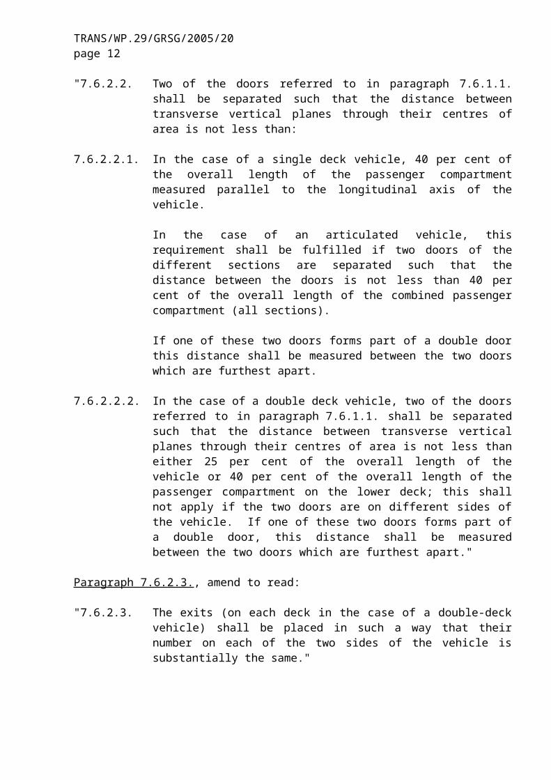
Paragraph 7.6.2.2., amend to read:
"7.6.2.2. Two of the doors referred to in paragraph 7.6.1.1. shall be separated such that the distance between transverse vertical planes through their centres of area is not less than:
7.6.2.2.1. In the case of a single deck vehicle, 40 per cent of the overall length of the passenger compartment measured parallel to the longitudinal axis of the vehicle.
In the case of an articulated vehicle, this requirement shall be fulfilled if two doors of the different sections are separated such that the distance between the doors is not less than 40 per cent of the overall length of the combined passenger compartment (all sections).
If one of these two doors forms part of a double door this distance shall be measured between the two doors which are furthest apart.
7.6.2.2.2. In the case of a double deck vehicle, two of the doors referred to in paragraph 7.6.1.1. shall be separated such that the distance between transverse vertical planes through their centres of area is not less than either 25 per cent of the overall length of the vehicle or 40 per cent of the overall length of the passenger compartment on the lower deck; this shall not apply if the two doors are on different sides of the vehicle. If one of these two doors forms part of a double door, this distance shall be measured between the two doors which are furthest apart."
Paragraph 7.6.2.3., amend to read:
"7.6.2.3. The exits (on each deck in the case of a double-deck vehicle) shall be placed in such a way that their number on each of the two sides of the vehicle is substantially the same."
Paragraph 7.6.2.4., amend to read:
"7.6.2.4. At least one emergency exit shall be situated either in the rear face or in the front face of the vehicle respectively. For Class I vehicles and for vehicles with a rear part permanently closed off from the passenger compartment, this provision is fulfilled if an escape hatch is fitted. For double-deck vehicles, this requirement shall apply only to the upper deck."

TRANS/WP.29/GRSG/2005/20page 9
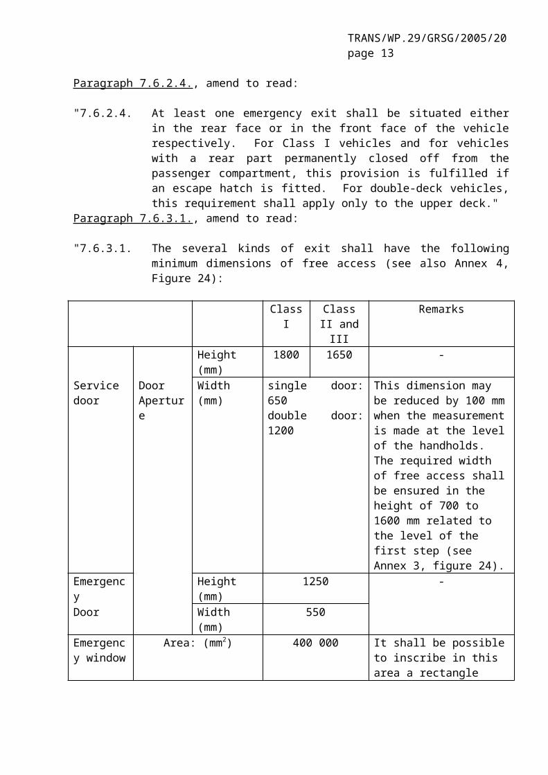
Paragraph 7.6.3.1., amend to read:
"7.6.3.1. The several kinds of exit shall have the following minimum dimensions of free access (see also Annex 4, Figure 24):
Class I Class II and III
Remarks
Height (mm) 1800 1650 -Service door Door
ApertureWidth (mm) single door: 650
double door: 1200This dimension may be reduced by 100 mm when the measurement is made at the level of the handholds. The required width of free access shall be ensured in the height of 700 to 1600 mm related to the level of the first step (see Annex 3, figure 24).
Emergency Height (mm) 1250 -Door Width (mm) 550Emergency window
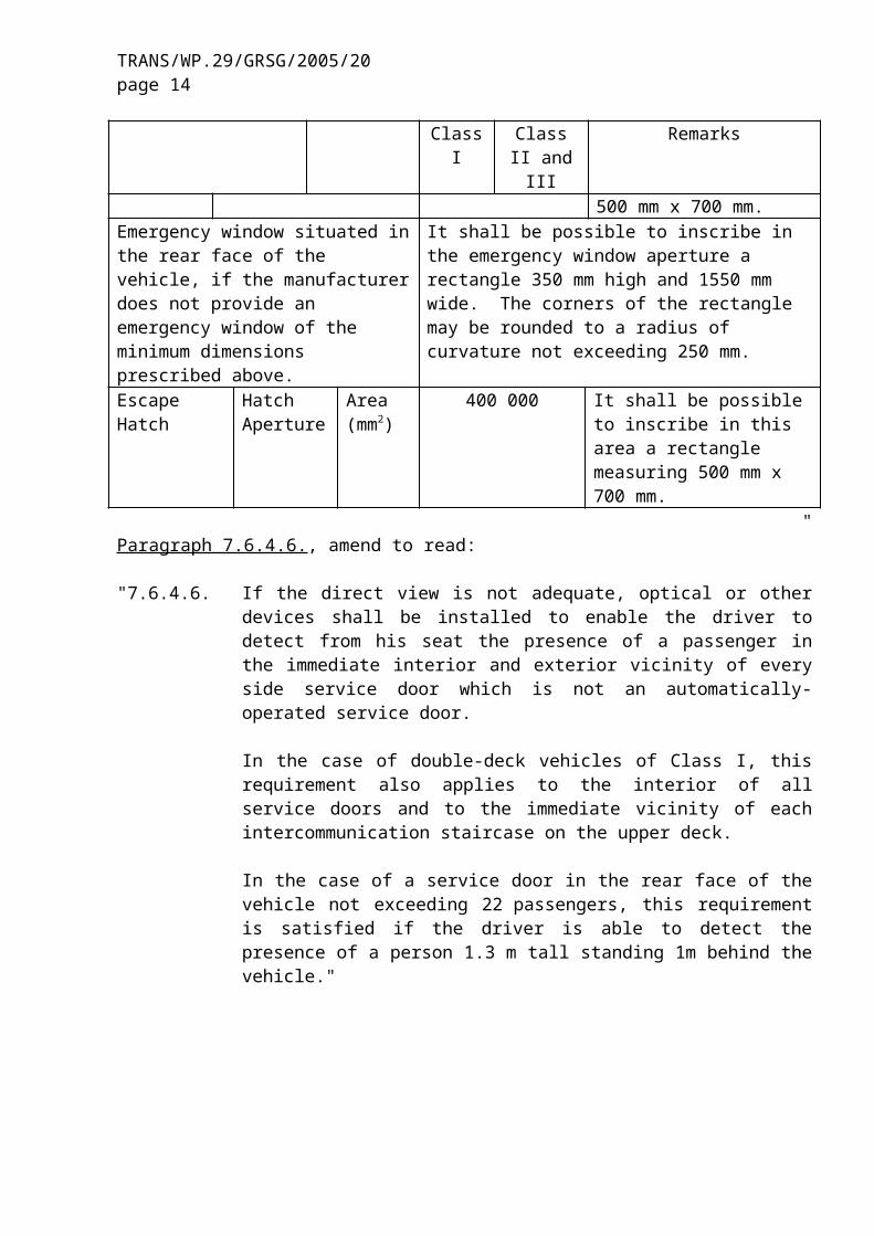
Area: (mm2) 400 000 It shall be possible to inscribe in this area a rectangle 500 mm x 700 mm.
Emergency window situated in the rear face of the vehicle, if the manufacturer does not provide an emergency window of the minimum dimensions prescribed above.
It shall be possible to inscribe in the emergency window aperture a rectangle 350 mm high and 1550 mm wide. The corners of the rectangle may be rounded to a radius of curvature not exceeding 250 mm.
Escape Hatch Hatch Aperture
Area (mm2)
400 000 It shall be possible to inscribe in this area a rectangle measuring 500 mm x 700 mm.
"Paragraph 7.6.4.6., amend to read:
"7.6.4.6. If the direct view is not adequate, optical or other devices shall be installed to enable the driver to detect from his seat the presence of a passenger in the immediate interior and exterior vicinity of every side service door which is not an automatically-operated service door.
In the case of double-deck vehicles of Class I, this requirement also applies to the interior of all service doors and to the immediate vicinity of each intercommunication staircase on the upper deck.
In the case of a service door in the rear face of the vehicle not exceeding 22 passengers, this requirement is satisfied if the driver is able to detect the presence of a person 1.3 m tall standing 1m behind the vehicle."
TRANS/WP.29/GRSG/2005/20page 10
Insert a new paragraph 7.6.4.10., to read:
"7.6.4.10. The service door in any open position shall not obstruct the use of, or required access to, any mandatory exit."
Paragraph 7.6.5.1.2., amend to read:
"7.6.5.1.2. in the case of interior controls, are placed on, or within 300 mm of, the door, at a height (except in the case of interior controls for the door referred to in Annex 8, paragraph 3.9.1) of not less than 1600 mm above the first step;"
Paragraph 7.6.5.1.7., amend to read:
"7.6.5.1.7. in the case of a driver-operated door which does not comply with the requirements of paragraph 7.6.5.6.2., shall be such that after they have been operated to open the door and returned to their normal position, the door will not close again until the driver subsequently operates a closing control."
Paragraph 7.6.7.3., amend to read:
"7.6.7.3. Every control or device for opening an emergency door (on the lower deck in the case of a double deck vehicle) from the outside shall be between 1000 mm and 1500 mm from the ground and not more than 500 mm from the door. In vehicles of Classes I, II and III every control or device for opening an emergency door from the inside shall be between 1000 mm and 1500 mm from the upper surface of the floor or step nearest to the control and be not more than 500 mm from the door. This shall not apply to controls located within the driver’s area."
Paragraph 7.6.10.9., amend to read:
"7.6.10.9. when the passenger door is open, the retractable step shall be securely held in the extended position. When a mass of 136 kg is placed in the centre of a single step or a mass of 272 kg is placed in the centre of a double step the deflection at any point on the step, measured from the body of vehicle, shall not exceed 10 mm."
Paragraph 7.7.1.6., amend to read:
"7.7.1.6. The free passage clearance for this figure shall not include any space extending to 300 mm in front of any uncompressed seat cushion of a forward or rearward facing seat, or 225 mm in the case of seats fitted at wheel arches, and to the height of the top of the seat cushion (see Annex 4, figure 25)."
Paragraph 7.7.1.7., amend to read:
"7.7.1.7. In the case of folding seats, this space shall be determined with the seat in the position of use."
Paragraph 7.7.1.11., amend to read:
TRANS/WP.29/GRSG/2005/20page 11
"7.7.1.11. The maximum slope of the floor in the access passage shall not exceed 5 per cent."
Insert a new paragraph 7.7.1.12., to read:
"7.7.1.12. The surface of access passages shall be slip-resistant."
Paragraph 7.7.4.1.1., amend to read:
"7.7.4.1.1. Except in the case of Class I and A vehicles, at least one escape hatch shall be located such that a four-sided truncated pyramid having a side angle of 20 degrees and a height of 1600 mm touches part of a seat or equivalent support. The axis of the pyramid shall be vertical and its smaller section shall contact the aperture area of the escape hatch. Supports may be foldable or movable provided they can be locked in their position of use. This position shall be taken for verification."
Paragraph 7.7.5.1., amend to read:
"7.7.5.1. The gangway(s) of a vehicle shall be so designed and constructed as to permit the free passage of a gauging device consisting of two co-axial cylinders with an inverted truncated cone interposed between them, the gauging device having the dimensions shown in Annex 4 figure 6.
The gauging device may come into contact with strap hangers, if fitted, or other flexible objects such as seat belt components and move them away."
Paragraphs 7.7.5.2. to 7.7.5.2.2., amend to read:
"7.7.5.2. (reserved)"
Paragraph 7.7.5.4., amend to read:
"7.7.5.4. On articulated vehicles, the gauging device defined in paragraph 7.7.5.1. shall be able to pass unobstructed through the articulated section on any deck where the two sections permit through passage by passengers. No part of the soft covering of that section, including parts of bellows, shall project into the gangway."
Paragraph 7.7.5.9., delete the words "and access passages".
Paragraphs 7.7.6. to 7.7.6.2., amend to read:
"7.7.6. Slope of gangway
The slope of the gangway shall not exceed:
7.7.6.1. in the longitudinal direction:
TRANS/WP.29/GRSG/2005/20page 12
7.7.6.1.1. 8 per cent in the case of a vehicle of Class I, II or A, or
7.7.6.1.2. 12.5 per cent in the case of a vehicle of Class III and B, and
7.7.6.2. In the transversal direction, 5 per cent for all classes."
Paragraph 7.7.7.1., amend to read:
"7.7.7.1. The maximum and minimum height, with the kneeling system not activated, and the minimum depth of steps for passengers at service and emergency doors and within the vehicle are specified in Annex 4, figure 8."
Paragraph 7.7.7.7., amend to read:
"7.7.7.7. The maximum slope of the step in any direction shall not exceed 5 per cent."
Paragraph 7.7.8., amend to read:
"7.7.8. Passenger seats (including folding seats) and space for seated passengers"
Paragraph 7.7.8.1., amend to read:
"7.7.8.1. Minimum seat width (see Annex 4, figure 9)"
Insert a new paragraph 7.7.8.1.5., to read:
"7.7.8.1.5. In measuring the gangway width, no account shall be taken of whether or not the available space defined above protrudes into the gangway."
Paragraph 7.7.8.4.5., amend to read:
"7.7.8.4.5. Measurements shall be taken with any folding table fitted to a seat back in the folded (stowed) position."
Paragraph 7.7.8.5.1., amend to read:
"7.7.8.5.1. A minimum clear space in front of each passenger seat shall be provided as shown in Annex 4, figure 13. The seat-back of another preceding seat or a partition whose contour corresponds approximately to that of the inclined seat back may intrude into this space as provided by paragraph 7.7.8.6. The local presence in this space of seat legs shall also be permitted provided that adequate space remains for the passenger's feet. In the case of seats alongside the driver's seat in vehicles with up to 22 passengers, intrusion of the dashboard, instrument panel, windscreen, sun visor, seat belts and seat belt anchorages shall be allowed."
TRANS/WP.29/GRSG/2005/20page 13
Paragraph 7.7.8.6.1., amend to read:
"7.7.8.6.1. In the case of single deck vehicles, over each seating position and, except in the case of the front row seats in a vehicle not exceeding 22 passengers, its associated foot space, there shall be measured a free space with a height of not less than 900 mm measured from the highest point of the uncompressed seat cushion and at least 1350 mm from the mean level of the floor in the foot space. In the case of vehicles to which paragraph 7.7.1.10. applies, this dimension may be reduced to 1200 mm measured from the floor.
In the case of double deck vehicles, each seating position shall have a free height of not less than 900 mm measured from the highest point of the uncompressed seat cushion. This free height shall extend over the vertical projection of the whole area of the seat and the associated foot space. In the case of the upper deck, this free height may be reduced to 850 mm."
Paragraph 7.7.8.6.3.1., amend to read:
"7.7.8.6.3.1. in the case of the upper part of the outboard seats, adjacent to the inner wall of the vehicle, a zone with a rectangular cross-section 150 mm in height and 100 mm in width (see Annex 4, figure 14)."
Paragraph 7.7.7.8.6.3.2., amend to read:
"7.7.8.6.3.2. in the case of the upper part of outboard seats, a zone with a triangular cross-section whose apex is situated 700 mm from the top and whose base is 100 mm in width (see Annex 4, figure 15);"
Paragraph 7.7.8.6.4.3., amend to read:
"7.7.8.6.4.3. In the case of seats alongside the driver's seat in vehicles with up to 22 passengers, intrusion of the dashboard / instrument panel, windscreen, sun visors, seat belts, seat belt anchorages and front dome."
Insert a new paragraph 7.7.8.4.4., to read:
"7.7.8.6.4.4. Intrusion of hopper type windows when open and their fittings."
Insert a new paragraph 7.7.9.3., to read:
"7.7.9.3. Communication with the toilet compartment
Toilet compartments shall be fitted with a means of summoning assistance in an emergency."
Insert new paragraphs 7.7.12. to 7.7.12.3., to read:
"7.7.12. Intercommunication staircase of a double-deck vehicle (see Annex 4, figure 1).
TRANS/WP.29/GRSG/2005/20page 14
7.7.12.1. The minimum width of any intercommunication staircase shall be so designed as to permit the free passage of the single door access template as defined in figure 1 of Annex 4. The panel shall be moved starting from the gangway of the lower deck up to the last step, in the probable direction of motion of a person using the staircase.
7.7.12.2. Intercommunication staircases shall be so designed, that, during heavy braking of the vehicle moving in the forward direction, there is no danger of a passenger being projected downwards.
This requirement is considered to be fulfilled if at least one of the following conditions is met:
7.7.12.2.1. no part of the staircase is forward descending;
7.7.12.2.2. the staircase is equipped with guards or a similar provision;
7.7.12.2.3. there is an automatic device in the upper part of the staircase which prevents the use of the staircase when the vehicle is in motion; this device shall be easily operable in an emergency.
7.7.12.3. It shall be verified, by use of the cylinder of paragraph 7.7.5.1., that access conditions from the gangways (upper and lower) to the staircase are adequate."
Paragraph 7.8., amend to read:
"7.8. Artificial interior lighting"
Insert a new paragraph 7.8.4., to read:
"7.8.4. Individual lights for each of the items in paragraph 7.8.1. are not required providing adequate illumination can be maintained during normal use."
Paragraph 7.11.2.3., amend to read:
"7.11.2.3. For every position that can be occupied by a standing passenger, at least one of the two required handrails or handholds shall be not more than 1500 mm above the level of the floor at that position. This does not apply to an area adjacent to a door where the door or its mechanism in open position would prevent the use of this handhold. Also, exception may be given in the middle of large platforms, but the sum of these exceptions shall not exceed 20 per cent of the total standing area."
Insert new paragraphs 7.11.5. to 7.11.5.2.2., to read:
"7.11.5. Handrails and handholds for intercommunication staircases in double deck vehicles.
TRANS/WP.29/GRSG/2005/20page 15
7.11.5.1. Suitable handrails or handholds shall be provided at each side of all intercommunication staircases. These shall be positioned between 800 mm and 1100 mm above the tread edge of each step.
7.11.5.2. The handrails and/or handholds to be provided shall be such that they include a grasping point available to a person standing on the lower or upper deck adjacent to the intercommunication staircase, and at any of the successive steps. Such points shall be situated vertically between 800 mm and 1100 mm above the lower deck or each above the surface of each step, and,
7.11.5.2.1. for the position appropriate to a person standing on the lower deck, not more than 400 mm inwards from the outer edge of the first step, and
7.11.5.2.2. for the position appropriate to a particular step, not outwards from the outer edge of the step considered, and not more than 600 mm inwards from the same edge."
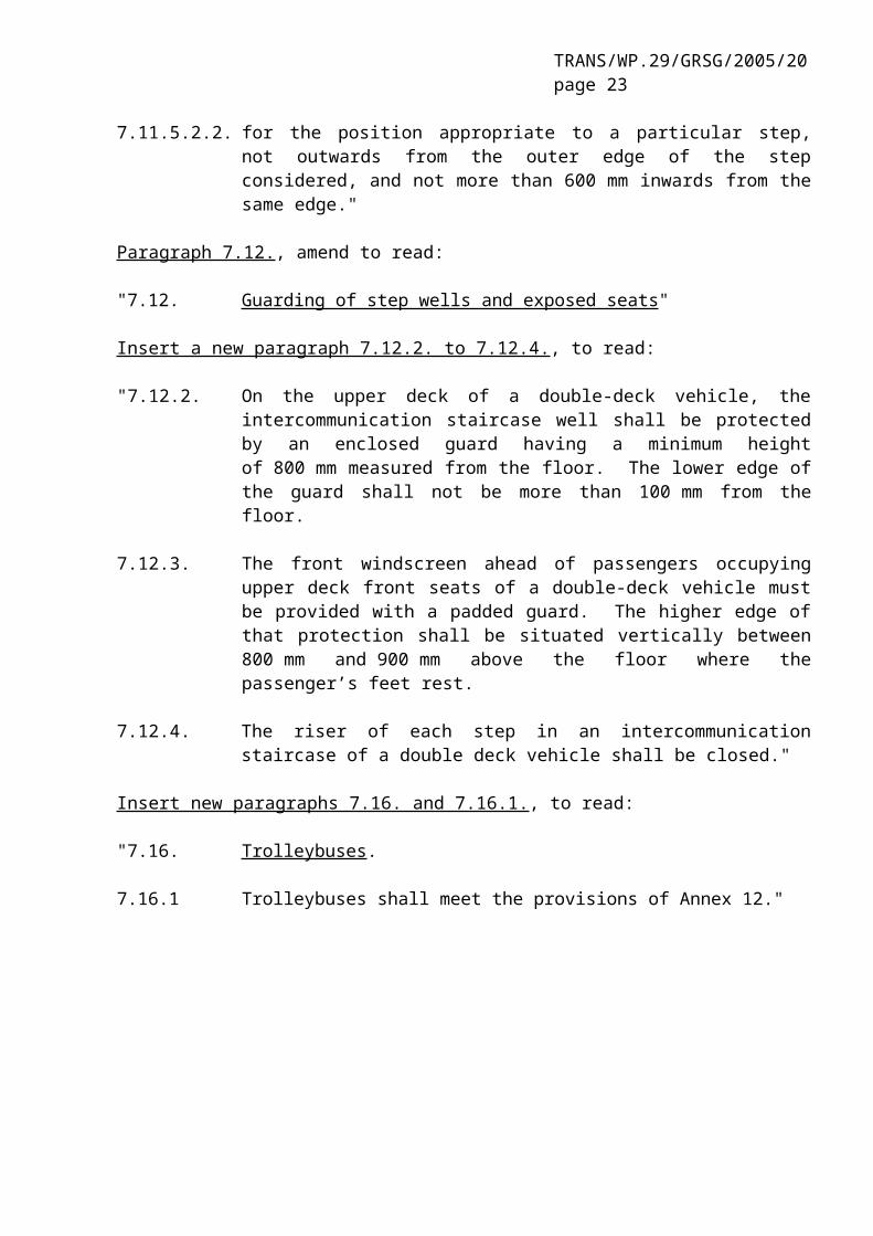
Paragraph 7.12., amend to read:
"7.12. Guarding of step wells and exposed seats"
Insert a new paragraph 7.12.2. to 7.12.4., to read:
"7.12.2. On the upper deck of a double-deck vehicle, the intercommunication staircase well shall be protected by an enclosed guard having a minimum height of 800 mm measured from the floor. The lower edge of the guard shall not be more than 100 mm from the floor.
7.12.3. The front windscreen ahead of passengers occupying upper deck front seats of a double-deck vehicle must be provided with a padded guard. The higher edge of that protection shall be situated vertically between 800 mm and 900 mm above the floor where the passenger’s feet rest.
7.12.4. The riser of each step in an intercommunication staircase of a double deck vehicle shall be closed."
Insert new paragraphs 7.16. and 7.16.1., to read:
"7.16. Trolleybuses.
7.16.1 Trolleybuses shall meet the provisions of Annex 12."
TRANS/WP.29/GRSG/2005/20page 16
Annex 4,
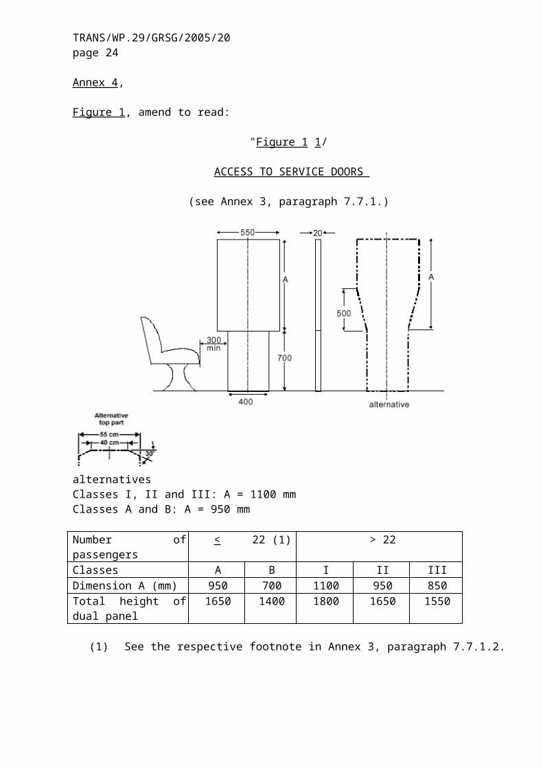
Figure 1, amend to read:
"Figure 1 1/
ACCESS TO SERVICE DOORS
(see Annex 3, paragraph 7.7.1.)
alternativesClasses I, II and III: A = 1100 mmClasses A and B: A = 950 mm
Number of passengers < 22 (1) > 22Classes A B I II IIIDimension A (mm) 950 700 1100 950 850Total height of dual panel 1650 1400 1800 1650 1550
(1) See the respective footnote in Annex 3, paragraph 7.7.1.2.
_____________1/ "Alternative top part" diagram should be revised before publication to refer to "550 mm" and "400 mm" as appropriate."
TRANS/WP.29/GRSG/2005/20page 17
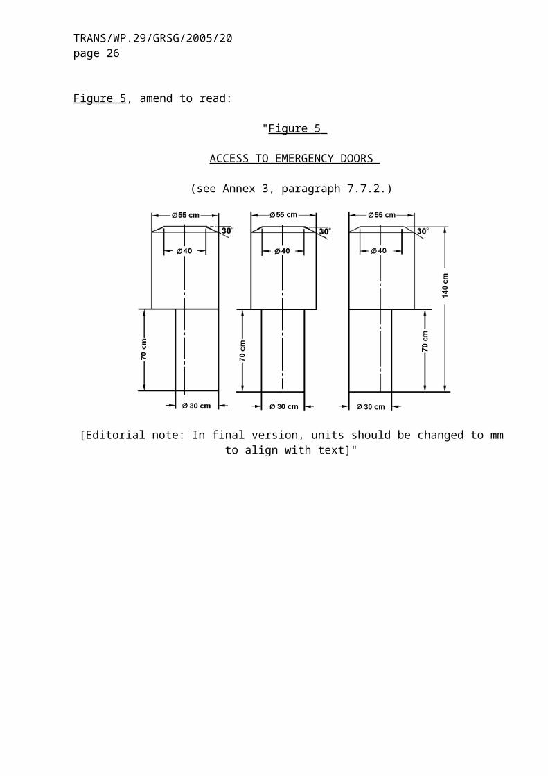
Figure 5, amend to read:
"Figure 5
ACCESS TO EMERGENCY DOORS
(see Annex 3, paragraph 7.7.2.)
[Editorial note: In final version, units should be changed to mm to align with text]"
TRANS/WP.29/GRSG/2005/20page 18
Figure 6, amend to read:
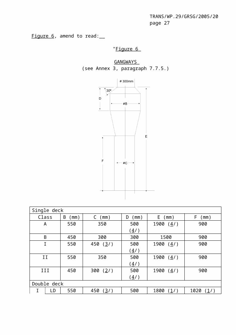
"Figure 6
GANGWAYS (see Annex 3, paragraph 7.7.5.)
Single deckClass B (mm) C (mm) D (mm) E (mm) F (mm)
A 550 350 500 (4/) 1900 (4/) 900B 450 300 300 1500 900I 550 450 (3/) 500 (4/) 1900 (4/) 900II 550 350 500 (4/) 1900 (4/) 900III 450 300 (2/) 500 (4/) 1900 (4/) 900
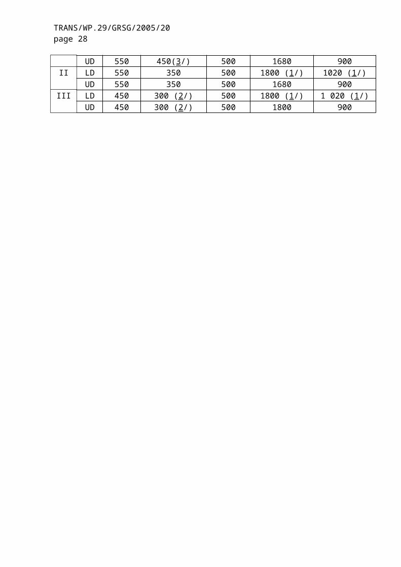
Double deckI LD 550 450 (3/) 500 1800 (1/) 1020 (1/)
UD 550 450(3/) 500 1680 900II LD 550 350 500 1800 (1/) 1020 (1/)
UD 550 350 500 1680 900III LD 450 300 (2/) 500 1800 (1/) 1 020 (1/)
UD 450 300 (2/) 500 1800 900
TRANS/WP.29/GRSG/2005/20page 19
(1/) The overall height of the gauging device may be reduced (by reducing the height of the lower cylinder):(a) from 1800 mm to 1680 mm in any part of the gangway of the lower deck to the rear of a
transverse vertical plane situated 1500 mm forward to the centre of the rear axle (foremost rear axle in the case of vehicles with more than one rear axle),
(b) from 1800 mm to 1770 mm in the case of a service door which is situated forward the front axle in any part of the gangway situated between two transverse vertical planes situated 800 mm forwards and behind the centre line of the front axle.
(2/) 220mm in the case of laterally movable seats (see paragraph 7.7.5.3).(3/) The diameter of the lower cylinder may be reduced from 450 mm to 400 mm in any part of
the gangway to the rear of the most forward of the following two planes:(a) a transverse vertical plane situated 1.5 m forward of the centre line of the rear axle
(foremost rear axle in the case of vehicles with more than one rear axle); and(b) a transverse vertical plane situated at the rear edge of the rearmost service door in
between the axles.For the purpose of the above, each rigid section of an articulated vehicle shall be considered separately.
(4/) The height of the upper cylinder and herewith the overall height may be reduced by 100 mm in any part of the gangway to the rear of:(a) a transverse plane situated 1.5 m forward of the centre line of the rear axle (foremost rear
axle in the case of vehicles with more than one rear axle), and(b) a transverse vertical plane situated at the rear edge of the service door or of the rearmost
service door if there are more than one service door."
TRANS/WP.29/GRSG/2005/20page 20
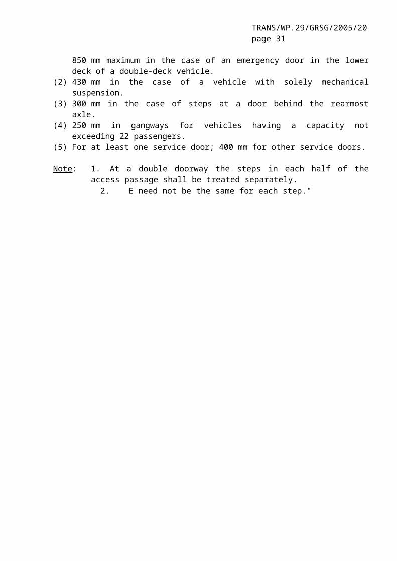
Figure 8, amend to read:
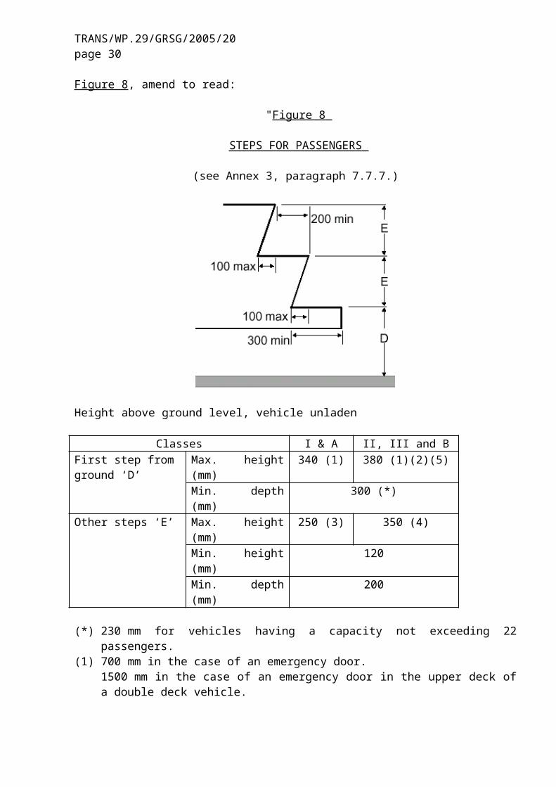
"Figure 8
STEPS FOR PASSENGERS
(see Annex 3, paragraph 7.7.7.)
Height above ground level, vehicle unladen
Classes I & A II, III and BFirst step from ground ‘D’
Max. height (mm) 340 (1) 380 (1)(2)(5)
Min. depth (mm) 300 (*)Other steps ‘E’ Max. height (mm) 250 (3) 350 (4)
Min. height (mm) 120Min. depth (mm) 200
(*) 230 mm for vehicles having a capacity not exceeding 22 passengers.(1) 700 mm in the case of an emergency door.
1500 mm in the case of an emergency door in the upper deck of a double deck vehicle.850 mm maximum in the case of an emergency door in the lower deck of a double-deck vehicle.
(2) 430 mm in the case of a vehicle with solely mechanical suspension.(3) 300 mm in the case of steps at a door behind the rearmost axle.(4) 250 mm in gangways for vehicles having a capacity not exceeding 22 passengers.(5) For at least one service door; 400 mm for other service doors.
Note: 1. At a double doorway the steps in each half of the access passage shall be treated separately.
2. E need not be the same for each step."

TRANS/WP.29/GRSG/2005/20page 21
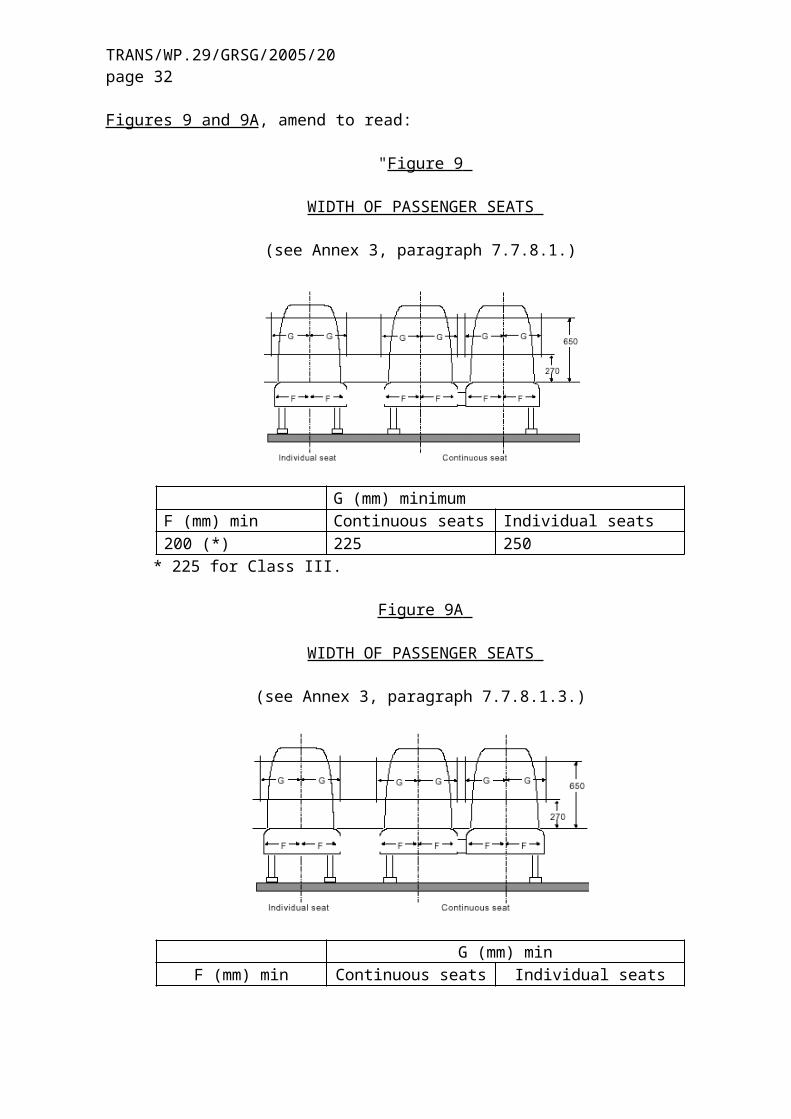
Figures 9 and 9A, amend to read:
"Figure 9
WIDTH OF PASSENGER SEATS
(see Annex 3, paragraph 7.7.8.1.)
G (mm) minimumF (mm) min Continuous seats Individual seats200 (*) 225 250
* 225 for Class III.
Figure 9A
WIDTH OF PASSENGER SEATS
(see Annex 3, paragraph 7.7.8.1.3.)
G (mm) minF (mm) min Continuous seats Individual seats
200 200 200"
TRANS/WP.29/GRSG/2005/20page 22
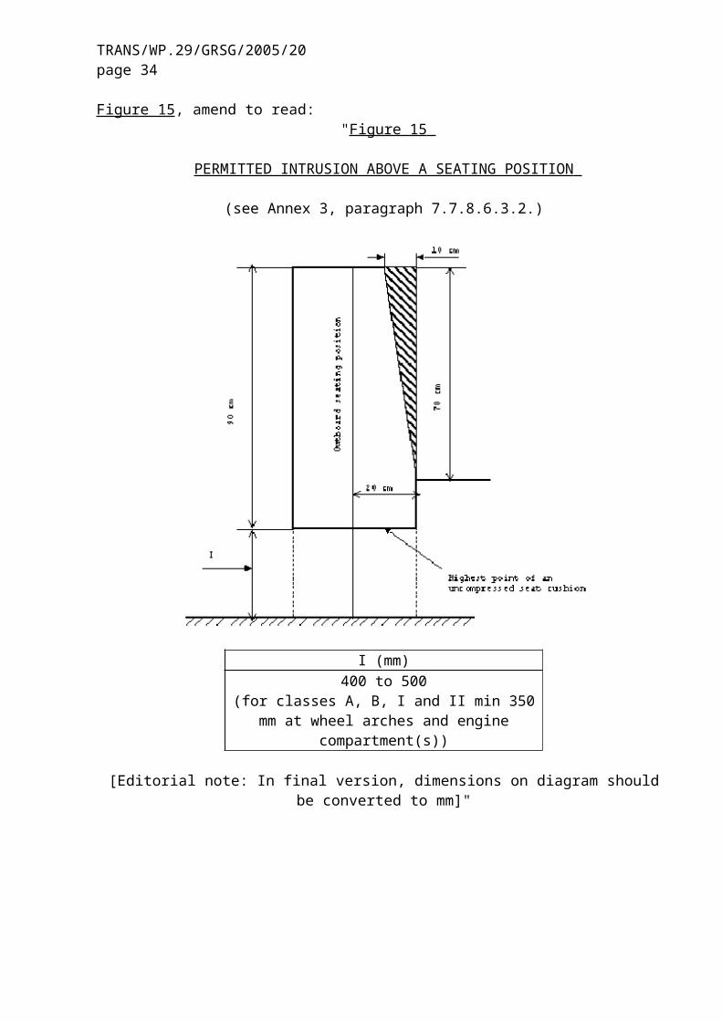
Figure 15, amend to read:"Figure 15
PERMITTED INTRUSION ABOVE A SEATING POSITION
(see Annex 3, paragraph 7.7.8.6.3.2.)
I (mm)400 to 500
(for classes A, B, I and II min 350 mm at wheel arches and engine compartment(s))
[Editorial note: In final version, dimensions on diagram should be converted to mm]"
TRANS/WP.29/GRSG/2005/20page 23
Figure 20, amend to read:
"Figure 20
TESTING DEVICE FOR SITING OF HANDHOLDS
(see Annex 3, paragraph 7.11.2.1.)
Thickness: 2cm."
Figure 23, amend to read:
"Figure 23
ACCESSIBILITY SYMBOLS(see Annex 8, paragraph 3.4.)
(diagrams unchanged)"
TRANS/WP.29/GRSG/2005/20page 24
Insert new figures 24 to 26, to read:
"Figure 24
SERVICE DOOR FREE ACCESS
(see Annex 3, paragraph 7.6.3.1.).
TRANS/WP.29/GRSG/2005/20page 25
Figure 25
PASSENGER FOOT SPACE
(see Annex 4, paragraph 7.7.1.6.)
Figure 26
ROOF ESCAPE HATCH ACCESS
(see Annex 4, paragraph 7.7.4.1.1.)
"
TRANS/WP.29/GRSG/2005/20page 26
Annex 5, delete text and replace by:
"Annex 5
(Reserved)"
Annex 7,
Paragraph 1.1., amend to read:
"1.1. Minimum dimensions for exits
The several kinds of exits shall have the following minimum dimensions:(table unchanged)
Annex 9, delete text and replace by:
"Annex 9
(Reserved)"
Insert a new Annex 12, to read:
"Annex 12
ADDITIONAL SAFETY PRESCRIPTIONS FOR TROLLEYBUSES
1. DEFINITIONS AND OPERATING PARAMETERS
For the purpose of this annex:
1.1. "Line voltage" means the voltage provided to the vehicle from the external power supply.
Trolleybuses shall be designed to operate at a rated line voltage of either:- 600 V (a working range of 400 to 720 V); or- 750 V (a working range of 500 to 900 V).
1.2. The electrical circuits of a trolleybus are classified as:
1.2.1. "high voltage circuits" means circuits energised at line voltage;
1.2.2. "low voltage circuits " means circuits energised at a nominal voltage of 12 V, 24 V or 42 V.
1.2.3. "three phase circuits" means circuits supplied with a three-phase voltage not exceeding 400 V AC.
TRANS/WP.29/GRSG/2005/20page 27
1.3. Rated climatic conditions
Trolleybuses shall be designed to operate reliably under the following environmental conditions:
1.3.1. a temperature range of minus 40 С to plus 40 С;
1.3.2. a relative humidity of 98 per cent at temperatures up to 25 С;
1.3.3. an atmospheric pressure range of 866 kPa to 1,066 kPa;
1.3.4. an altitude range from sea level to a maximum of 1,000 m above sea level.
1.4. "Self-extinguishing material" means a material that does not continue to burn when the ignition source is removed.
2. POWER COLLECTION
2.1. Electrical power shall be obtained from the contact wires by means of one or more power collection devices, normally comprising two trolley booms. (A single trolley boom or a pantograph may be used in guided applications). A trolley boom shall consist of a roof mounting (trolley base), a pole, an electrical power collector (trolley head) and a replaceable contact surface insert. Trolley booms shall be mounted so that they can turn in both horizontal and vertical directions.
2.2. Poles shall be made of an insulated material or of metal covered with insulating material and shall be resistant to mechanical shocks.
2.3. Power collectors shall be designed to maintain adequate positive contact with the contact wires when the wires are located at between 4 and 6 metres above the ground and, in the case of trolley booms, to allow the longitudinal axis of the trolleybus to deviate at least 4.0 metres to either side of the mean axis of the contact wires.
2.4. If the power collector becomes accidentally detached from the contact wire (de-wired), the upper end of the power collector(s) shall not be raised higher than 7.2 metres above the road, or 1 metre maximum above the contact wires at the time of de-wiring, nor lower than 0.5 metres above the roof of the trolleybus.
2.5. Each trolley boom shall be equipped with a device which retracts the boom automatically if the pole unwires.
2.6. The trolley head, if dismounted from its normal position on the pole, shall be remain attached to the pole and must not fall down.
2.7. The insulation resistance between the electric power collector and the roof mounting/trolley base shall be at least 10 М:
TRANS/WP.29/GRSG/2005/20page 28
2.8. Power collectors may be equipped with remote control from the driver’s compartment, at least for retraction.
2.9. Provision shall be made to enable the driver to replace, if necessary, contact surface inserts while the vehicle is in operation on the road.
3. TRACTION AND AUXILIARY EQUIPMENT
3.1. Electrical components installed on the trolleybus shall be protected against over-voltage and short-circuit current. The protection shall preferably be assured by circuit breakers that are reset automatically, remotely or manually.
3.2. Electrical components shall be protected against commutation or atmospheric over-voltage.
3.3. Circuit breakers shall provide interruption of particular damaged circuits.
3.4. If any circuit includes a single-pole circuit breaker, it shall be installed in the positive wire of the circuit.
3.5. All electrical circuits and circuit branches shall be of dual wiring. The trolleybus body can be used for current earth return only for low voltage circuits.
3.6. Battery cases, covers and trays shall be made of non-flammable or self-extinguishing materials.
3.7. Electrical components energized at the line voltage shall have additional insulation from the vehicle.
3.8. Electrical components, with the exception of traction resistors, shall be protected against penetration of moisture and dust into the body and onto insulated and current conducting parts.
3.9. Within the rated climate conditions, with the trolleybus dry and clean, the insulation resistance of electrical circuits, when all rotating machines and apparatus are switched on, shall not be less than:
3.9.1. body to high voltage circuits 5 M
3.9.2. high voltage circuits to low voltage circuits 5 M
3.9.3. body to positive pole of low voltage circuits 1 M
3.10. Wiring and apparatus
3.10.1. Only multi-core wires shall be used for high voltage circuits. All high voltage DC wiring shall have insulation rated for 3,000 V DC or AC.
TRANS/WP.29/GRSG/2005/20page 29
3.10.2. Mounted wiring should not be stressed mechanically.
3.10.3. Wiring insulation shall not propagate burning.
3.10.4. Wiring of different voltages shall be mounted separately.
3.10.5. Wiring conduits shall be made of non-flammable material.
3.10.6. [Reserved]
3.10.7. Wiring located under the floor of the trolleybus shall be contained in conduit that protects it against the ingress and propagation of water and dust.
3.10.8. Fastening and arrangement of wiring and cables shall be designed to prevent damage by abrasion (chafing) of insulation. Grommets of elastomeric material shall be provided at points where wiring penetrates metal structure. The bend radius of conduits containing wiring shall be at least five times the external diameter of the conduit.
3.10.9. The location of wiring in the vicinity of circuit breakers shall be designed so as to prevent arcing onto the wiring.
3.10.10. Precautions shall be taken to avoid damage of wiring from heated resistors and other electrical components. In critical areas thermo-resistant wires shall be used.
3.10.11. Wiring holders, connectors and other mounting devices shall be made of non-flammable or self-extinguishing materials. Electrical components of the self-extinguishing materials shall only be installed outside the passenger compartment.
3.10.12. All electrical circuits shall undergo an excess voltage test. The test voltage shall be AC with a frequency of 50 Hz and approximately sinusoidal form. The time of application of the test voltage shall be 1 min.
3.10.12.1. The test voltage Utest for electrical equipment and wiring for high voltage circuits shall be:
Utest = 2.5 U + 2,000 V AC,
where U is the rated line voltage
3.10.12.2. The test voltage for low voltage circuits shall be U test = 750 V AC.
3.11. Electrical machines, apparatus, devices and wiring shall withstand mechanical loads, applied to mounting points, as follows:
3.11.1. sine-wave form vibration of 0.5 - 55 Hz frequency and 10 m/s2 maximum amplitude including resonance if produced;
TRANS/WP.29/GRSG/2005/20page 30
3.11.2. vertical discrete shocks of 30 m/s2 peak shock acceleration lasting 2 - 20 ms.
4. ELECTRICAL SAFETY OF PASSENGERS AND CREW
4.1. At the rated climate conditions, with the trolleybus dry and clean and connected to both positive and negative power supply via the power collection devices, the earth leakage current from the body shall not be higher than 0.2 mA.
4.2. The trolleybus must be equipped with an onboard device for permanent monitoring of leakage current or voltage between the chassis and the road surface. The device shall disconnect the high voltage circuits from the contact system if the leakage current exceeds 3 mA at a line voltage of 600 V DC, or if the leakage voltage exceeds 40 V.
4.3. Stanchions and handrails at doorways shall be made of insulating material or covered with mechanically durable insulation or insulated from the trolleybus body. The insulation resistance shall at least be 1.0 M over a contact area of 100 ± 5 cm2.
4.4. The first steps shall be made of insulating material or covered with mechanically durable insulation. The insulation resistance shall at least be 1.0 M over a contact area of 300 ± 5 cm2.
4.5. Door panels shall be made of insulating material or insulated from the trolleybus body. The insulation resistance shall be at least 1.0 M over a contact area on the panel of 300 ± 5 cm2.
4.6. The external body panels adjacent to the door apertures shall be covered with insulating material. The insulated area shall extend in width at least 50 cm each side of the door apertures and in height at least 200 cm from the roadway. The insulation resistance in respect to the trolleybus body shall not be less than 1.0 M over a contact area of 200 ± 5 cm2.
4.7 If the trolleybus is equipped with double-insulated converters, paragraphs 4.3. to 4.6. need not be applied.
5. THE DRIVER’S COMPARTMENT
5.1. In the driver’s compartment, there should not be any high voltage equipment accessible by the driver.
5.2. As a minimum, the instrument panel shall include:
5.2.1. indicator of voltage in the contact system;
5.2.2. indicator of zero voltage in the contact system;
5.2.3. indicator of state of main automatic line voltage circuit breaker;
TRANS/WP.29/GRSG/2005/20page 31
5.2.4. indicator of charge/discharge of the batteries;
5.2.5.. indicator of body voltage or leakage current exceeding the limits specified in paragraph 4.2.
TRANS/WP.29/GRSG/2005/20page 32
B. CORRELATION TABLE
This Draft 107.01 Notes2.1.8 Reg.36, 2.1.4 A2.15.1. 2.15.1. F2.27. 2.27. DEF4.2. 4.2. G5.1. 5.1. S10.1. 10.1. G10.2. 10.2. G10.3. 10.3. G10.4. 10.4. G10.5 - MAnnex 1 Annex 1Part 1 Part 1Appendix 1 Appendix 1 DAppendix 2 Appendix 2 DAnnex 2 Annex 2 GAnnex 3 Annex 37.2.2.2. 7.2.2.2. DF7.3.1. 7.3.1. H7.4.2.1. 7.4.2.1. I7.5.2.3. 7.5.2.3. DEF7.5.4.1. 7.5.4.1. I7.5.5. 7.5.5. D7.6.1.1. 7.6.1.1. I7.6.1.4. 7.6.1.4. I7.6.1.5. 7.6.1.5. DF7.6.1.8. 7.6.1.8. F7.6.1.11. 7.6.1.11. I7.6.1.12 Annex 9, 7.6.1.12 I7.6.1.13 Annex 9, 7.6.1.12 I7.6.1.14 Annex 9, 7.6.1.12 I7.6.1.14.1 Annex 9, 7.6.1.12 (a) I7.6.1.14.2 Annex 9, 7.6.1.12 (b) I7.6.2.1. 7.6.2.1. E7.6.2.2. 7.6.2.2. I7.6.2.2.1 7.6.2.2. D7.6.2.2.2 Annex 9, 7.6.2.2. FI7.6.2.3. 7.6.2.3. I7.6.2.4. 7.6.2.4. I7.6.3.1. 7.6.3.1. DF7.6.4.6. 7.6.4.6. I7.6.4.10 Reg.36, 5.6.4.9 ABC
This Draft 107.01 NotesReg.52, 5.6.4.10Reg.107, 5.6.4.9
7.6.5.1.2. 7.6.5.1.2. U7.6.5.1.7. 7.6.5.1.7. J7.6.7.3. 7.6.7.3. I7.6.10.9. 7.6.10.9. DEF7.7.1.6. 7.7.1.6. F7.7.1.7. 7.7.1.7. E7.7.1.11. 7.7.1.11. EFK7.7.1.12 Reg.36, 5.7.1.10,
Reg.52, 5.7.1.11,Reg.107, 5.7.1.10
ABC
7.7.4.1.1. 7.7.4.1.1. E7.7.5.1. 7.7.5.1. T(7.7.5.2.) 7.7.5.2. T7.7.5.4. 7.7.5.4. I(7.7.5.8.) 7.7.5.8 I7.7.5.8.1 Annex 9, 7.7.5.11.(a) I7.7.5.8.2 Annex 9, 7.7.5.11.(b) I7.7.6. 7.7.6. DEF
K7.7.6.1 Reg.36, 5.7.6.1
Reg.52, 5.7.6.1,Reg.107, 5.7.7.1
ABC
7.7.6.2. 7.7.6.4. DEF7.7.7.1. 7.7.7.1. DEF7.7.7.7. 7.7.7.7. EFK7.7.8. 7.7.8. DEF7.7.8.1. 7.7.8.1. DEF7.7.8.1.5 Reg.107, 5.7.9.1.2.3 C7.7.8.4.5. 7.7.8.4.5. F7.7.8.5.1. 7.7.8.5.1. V7.7.8.6.1. 7.7.8.6.1. I7.7.8.6.3.1. 7.7.8.6.3.1. E7.7.8.6.3.2. 7.7.8.6.3.2. DEF7.7.8.6.4.3. 7.7.8.6.4.3. L7.7.8.6.4.4 Reg.36, 5.7.8.6.2.4
Reg.107, 5.7.9.6.2.4AC
7.7.9.3 Reg.107, 5.7.10.3 C7.7.12 Annex 9, 7.7.12 I7.7.12.1 Annex 9, 7.7.12.1 I7.7.12.2 Annex 9, 7.7.12.2 I

TRANS/WP.29/GRSG/2005/20page 33
This Draft 107.01 Notes7.7.12.2.1 Annex 9, 7.7.12.2.1 I7.7.12.2.2 Annex 9, 7.7.12.2.2 I7.7.12.2.3 Annex 9, 7.7.12.2.3 I7.7.12.3 Annex 9, 7.7.12.3 I7.8. 7.8. DEF7.8.4 Reg.107, 7.8.2 C7.11.2.3. 7.11.2.3. DEF7.11.5 Annex 9, 7.11.5 I7.11.5.1 Annex 9, 7.11.5.1 I7.11.5.2 Annex 9, 7.11.5.2 I7.11.5.2.1 Annex 9, 7.11.5.2.1 I7.11.5.2.2 Annex 9, 7.11.5.2.2 I7.12. 7.12. I7.12.2 Annex 9, 7.12.2 I7.12.3 Annex 9, 7.12.3 I7.12.4 Annex 9, 7.12.4 I7.16. - G7.16.1 Reg.36, 7.16 AAnnex 4 Annex 4Figure 1 Figure 1 NFigure 5 Figure 5 OFigure 6 Figure 6 TFigure 8 Figure 8 IFigure 9 Figure 9 PFigure 9A Figure 9A PFigure 15 Figure 15 DEFFigure 20 Figure 20 DFigure 24 Reg.36, Fig.12,
Reg.107, Fig.16.AC
Figure 25 Reg.107, Fig.15. CFigure 26 Reg.36, 5.7.4.1.1
Reg.52, 5.7.4.1Reg.107, 5.7.4.1
ABC
(Annex 5) Annex 5 HAnnex 7 Annex 71.1. 1.1. R(Annex 9) Annex 9 IAnnex 12 Reg.36, Annex 8 A
TRANS/WP.29/GRSG/2005/20page 34
Notes:A Incorporated from Regulation No.36.B Incorporated from Regulation No.52.C Incorporated from Regulation No.107.D Aligned with Regulation No.36.E Aligned with Regulation No.52.F Aligned with Regulation No.107.G Administrative update only.H Rationalised by reference to Regulation No. 66 in Annex 3, para. 7.3.1.I Annex 9 text merged into Annex 3 in the interests of clarity.J Word “it” should be deleted (grammatical correction).K See para. 7.1.1.L Consequential amendment to 7.7.8.6.4.4 below.M Consequential amendment to terminate granting of new approvals to Regulation Nos. 36
and 52 in accordance with normal procedure.N Aligned with text by adding “alternative top”, as recently done for Regulation No. 52.O Aligned with text by adding chamfer, as correctly shown in Regulation No. 52.P Title amended to correctly reflect content, as in Regulation Nos. 36 and 107.R Editorial correction.S Amendment consequential on abolition of Annexes 5 and 9.T Single deck and double deck requirements merged in common format. Table and
paragraphs qualifying dimensions of test gauge moved from Annex 3 and merged with Annex 4 table and footnotes to avoid duplication (as previously done for steps in Regulation No. 36). No change to dimensions but presentation commonised and notes adjusted to remove pre-existing conflicts between text and figures.
U Present text conflicts with Annex 8.V Correction to cross-reference.
- - - - -