
TransSynergic 4000/5000, TransPuls Synergic 2700, TransPuls ...
210
TÄYDELLISTÄ HITSAUSTA / Operating Instructions / Spare Parts List v.01/2012 ENG TRANSPULS SYNERGIC 2700/3200/4000/5000 TIME 5000 DIGITAL CMT 4000 ADVANCED
-
Upload
nguyenphuc -
Category
Documents
-
view
273 -
download
12
Transcript of TransSynergic 4000/5000, TransPuls Synergic 2700, TransPuls ...
TÄYDELLISTÄ HITSAUSTA
/ Operating Instructions/ Spare Parts List
v.01/2012 ENG
TRANSPULS SYNERGIC 2700/3200/4000/5000TIME 5000 DIGITALCMT 4000 ADVANCED

EN
Dear reader,
Introduction Thank you for the trust you have placed in our company and congratulations on buying this high-quality Fronius product. These instructions will help you familiarise yourself with the product. Reading the instructions carefully will enable you to learn about the many different features it has to offer. This will allow you to make full use of its advantages.
Please also note the safety rules to ensure greater safety when using the product. Careful handling of the product will repay you with years of safe and reliable operation. These are essential prerequisites for excellent results.
1

2
EN
Contents
Safety rules ................................................................................................................................................ 9Explanation of safety symbols .............................................................................................................. 9General ................................................................................................................................................. 9Intended purpose .................................................................................................................................. 10Environmental conditions...................................................................................................................... 10Obligations of the operator.................................................................................................................... 10Obligations of personnel ....................................................................................................................... 11Mains connection .................................................................................................................................. 11Protecting yourself and others .............................................................................................................. 11Noise emission values .......................................................................................................................... 12Danger from toxic gases and vapours .................................................................................................. 12Danger from flying sparks ..................................................................................................................... 13Risks from mains current and welding current...................................................................................... 13Meandering welding currents................................................................................................................ 15EMC device classifications ................................................................................................................... 15EMC measures ..................................................................................................................................... 15EMF measures...................................................................................................................................... 16Specific hazards.................................................................................................................................... 16Danger from shielding gas cylinders..................................................................................................... 18Safety measures at the installation location and during transport ........................................................ 18Safety measures in normal operation ................................................................................................... 19Maintenance and repair ........................................................................................................................ 20Safety inspection................................................................................................................................... 20Disposal ................................................................................................................................................ 20Safety symbols...................................................................................................................................... 20Data protection...................................................................................................................................... 21Copyright............................................................................................................................................... 21
General information 23
General ...................................................................................................................................................... 25Device concept ..................................................................................................................................... 25Functional principle ............................................................................................................................... 25Application areas .................................................................................................................................. 25Warning notices on the device.............................................................................................................. 25
Special versions......................................................................................................................................... 27General ................................................................................................................................................. 27Alu edition ............................................................................................................................................. 27CrNi edition ........................................................................................................................................... 27CMT Variants ........................................................................................................................................ 27CMT 4000 Advanced ............................................................................................................................ 27TIME 5000 Digital ................................................................................................................................. 28Yard edition........................................................................................................................................... 28Steel-Edition.......................................................................................................................................... 28
System components .................................................................................................................................. 29General ................................................................................................................................................. 29Overview............................................................................................................................................... 29
Control elements and connections 31
Description of the control panels................................................................................................................ 33General ................................................................................................................................................. 33Safety.................................................................................................................................................... 33Übersicht............................................................................................................................................... 33
Standard control panel............................................................................................................................... 34General ................................................................................................................................................. 34Standard control panel.......................................................................................................................... 34Key combinations - special functions.................................................................................................... 36Displaying the feeder inching speed ..................................................................................................... 36Displaying the gas pre-flow and gas post-flow time.............................................................................. 36
3
Displaying the software version ............................................................................................................ 36Comfort / CrNi / Steel control panel ........................................................................................................... 38
Unterscheidung Bedienpanel Comfort, CrNi und Steel......................................................................... 38Comfort control panel............................................................................................................................ 38Key combinations - special functions.................................................................................................... 41Displaying the feeder inching speed ..................................................................................................... 41Displaying the gas pre-flow and gas post-flow time.............................................................................. 42Displaying the software version ............................................................................................................ 42
US control panel ........................................................................................................................................ 43US control panel ................................................................................................................................... 43Key combinations - special functions.................................................................................................... 46Displaying the feeder inching speed ..................................................................................................... 46Displaying the gas pre-flow and gas post-flow time.............................................................................. 46Displaying the software version ............................................................................................................ 46
TIME 5000 Digital control panel................................................................................................................. 48TIME 5000 Digital control panel............................................................................................................ 48Key combinations - special functions.................................................................................................... 51Displaying the feeder inching speed ..................................................................................................... 51Displaying the gas pre-flow and gas post-flow time.............................................................................. 52Displaying the software version ............................................................................................................ 52
CMT control panel...................................................................................................................................... 53CMT control panel................................................................................................................................. 53Key combinations - special functions.................................................................................................... 56Displaying the feeder inching speed ..................................................................................................... 56Displaying the gas pre-flow and gas post-flow time.............................................................................. 56Displaying the software version ............................................................................................................ 56
Yard control panel...................................................................................................................................... 58Yard control panel................................................................................................................................. 58Key combinations - special functions.................................................................................................... 61Displaying the feeder inching speed ..................................................................................................... 61Displaying the gas pre-flow and gas post-flow time.............................................................................. 61Displaying the software version ............................................................................................................ 61
“Remote” control panel .............................................................................................................................. 63General ................................................................................................................................................. 63Remote control panel............................................................................................................................ 63
CMT Remote control panel ........................................................................................................................ 64General ................................................................................................................................................. 64CMT Remote and CMT Advanced control panel .................................................................................. 64
Connections, switches and mechanical components ................................................................................ 65TPS 2700 power source ....................................................................................................................... 65TPS 2700 CMT power source............................................................................................................... 66TS 4000 / 5000, TPS 3200 / 4000 / 5000, TIME 5000 Digital power sources ...................................... 67CMT 4000 Advanced power source...................................................................................................... 68
Installation and commissioning 71
Minimum equipment needed for welding task............................................................................................ 73General ................................................................................................................................................. 73MIG/MAG gas-cooled welding .............................................................................................................. 73MIG/MAG water-cooled welding ........................................................................................................... 73MIG/MAG automated welding............................................................................................................... 73CMT manual welding ............................................................................................................................ 73CMT automated welding ....................................................................................................................... 74CMT Advanced welding ........................................................................................................................ 74TIG DC welding..................................................................................................................................... 74Manual metal arc welding ..................................................................................................................... 74
Before installation and commissioning....................................................................................................... 75Safety.................................................................................................................................................... 75Proper use ............................................................................................................................................ 75Setup regulations .................................................................................................................................. 75Mains connection .................................................................................................................................. 75
Connecting up the mains cable on US power sources .............................................................................. 76General ................................................................................................................................................. 76Stipulated mains cables and strain-relief devices ................................................................................. 76
4
EN
Safety.................................................................................................................................................... 76Connecting the mains cable.................................................................................................................. 76Replacing the strain-relief device.......................................................................................................... 77
Start-up ...................................................................................................................................................... 79Safety.................................................................................................................................................... 79Remarks on the cooling unit ................................................................................................................. 79Information on system components ...................................................................................................... 79Overview............................................................................................................................................... 79
Commissioning the TPS 2700 ................................................................................................................... 80General ................................................................................................................................................. 80Recommendation for water-cooled applications ................................................................................... 80Connecting the gas cylinder.................................................................................................................. 80Establishing a ground (earth) connection ............................................................................................. 81Connecting the welding torch................................................................................................................ 81Inserting/replacing feed rollers.............................................................................................................. 81Inserting the wirespool .......................................................................................................................... 82Inserting the basket-type spool ............................................................................................................. 82Feeding in the wire electrode................................................................................................................ 83Setting the contact pressure ................................................................................................................. 84Adjusting the brake ............................................................................................................................... 84Design of the brake............................................................................................................................... 85
Commissioning the TS 4000 / 5000, TPS 3200 / 4000 / 5000, TIME 5000 Digital .................................... 86General ................................................................................................................................................. 86Fitting the system components (overview)............................................................................................ 86Fixing the strain-relief device in place................................................................................................... 87Connecting the interconnecting hosepack ............................................................................................ 87Connecting the gas cylinder.................................................................................................................. 88Establishing a ground (earth) connection ............................................................................................. 89Connecting the welding torch................................................................................................................ 89Other tasks............................................................................................................................................ 89
Commissioning the CMT4000 Advanced................................................................................................... 90Fitting the system components (overview)............................................................................................ 90Connecting the interconnecting hosepack, CMT welding torch and wire buffer ................................... 90Other tasks............................................................................................................................................ 90Preparing the wire-feed unit.................................................................................................................. 91
Welding 93
MIG/MAG modes ....................................................................................................................................... 95General ................................................................................................................................................. 95Symbols and their explanations ............................................................................................................ 952-step mode.......................................................................................................................................... 964-step mode.......................................................................................................................................... 96Special 4-step mode ............................................................................................................................. 97Spot welding ......................................................................................................................................... 97
MIG/MAG welding...................................................................................................................................... 98Safety.................................................................................................................................................... 98General tasks before MIG/MAG welding .............................................................................................. 98Overview............................................................................................................................................... 98
MIG/MAG synergic welding ....................................................................................................................... 99General ................................................................................................................................................. 99MIG/MAG synergic welding .................................................................................................................. 99Corrections during welding ................................................................................................................... 100Adjusting parameters for correction ...................................................................................................... 100Remarks on the Standard control panel ............................................................................................... 100
MIG/MAG standard manual welding .......................................................................................................... 101General ................................................................................................................................................. 101Available parameters ............................................................................................................................ 101MIG/MAG standard manual welding ..................................................................................................... 101Corrections during welding ................................................................................................................... 102Adjusting parameters for correction ...................................................................................................... 102
CMT welding .............................................................................................................................................. 103General ................................................................................................................................................. 103CMT welding ......................................................................................................................................... 103
5
Corrections during welding ................................................................................................................... 104Adjusting parameters for correction ...................................................................................................... 106
Special functions and options .................................................................................................................... 107Arc break watchdog function................................................................................................................. 107Ignition time-out function....................................................................................................................... 107Spatter-free ignition option.................................................................................................................... 107SynchroPulse option ............................................................................................................................. 108
Robot welding ............................................................................................................................................ 110Prerequisite........................................................................................................................................... 110General ................................................................................................................................................. 110Special 2-step mode for robot interface ................................................................................................ 110Wire-stick control function..................................................................................................................... 111Changing the welding process during CMT Advanced welding............................................................ 111
TIG welding................................................................................................................................................ 112Safety.................................................................................................................................................... 112Prerequisite........................................................................................................................................... 112Preparation ........................................................................................................................................... 112TIG welding........................................................................................................................................... 112Igniting the arc ...................................................................................................................................... 113Finishing welding .................................................................................................................................. 114TIG Comfort Stop option ....................................................................................................................... 114TIG welding with TIG Comfort Stop ...................................................................................................... 116
MMA welding ............................................................................................................................................. 117Safety.................................................................................................................................................... 117Prerequisite........................................................................................................................................... 117Preparation ........................................................................................................................................... 117Manual metal arc welding ..................................................................................................................... 117Corrections during welding ................................................................................................................... 118Adjusting parameters for correction ...................................................................................................... 118HotStart function ................................................................................................................................... 118SoftStart function .................................................................................................................................. 119Anti-stick function.................................................................................................................................. 119
Job mode ................................................................................................................................................... 120General ................................................................................................................................................. 120Prerequisites ......................................................................................................................................... 120Restrictions ........................................................................................................................................... 120Job mode displays on the left-hand digital display................................................................................ 120Selecting job mode as the process ....................................................................................................... 120Creating a job........................................................................................................................................ 120Retrieving a job ..................................................................................................................................... 121Copying/overwriting a job...................................................................................................................... 122Deleting a job ........................................................................................................................................ 123
Setup settings 125
Job correction ............................................................................................................................................ 127General ................................................................................................................................................. 127Opening the Job correction menu......................................................................................................... 127Changing welding parameters .............................................................................................................. 127Exiting the Job correction menu............................................................................................................ 127Parameters in the job correction menu ................................................................................................. 128Permanently settable parameters ......................................................................................................... 128Parameters that can be corrected at a later time.................................................................................. 130
Shielding gas setup menu.......................................................................................................................... 133General ................................................................................................................................................. 133Protective gas shield setup menu for the standard control panel ......................................................... 133Protective gas shield setup menu for the Comfort, US, TIME 5000 Digital and CMT control panels ... 133Welding parameters in the Protective gas shield setup menu .............................................................. 133
Setup menu for the standard control panel................................................................................................ 135General ................................................................................................................................................. 135Setup menu for the standard control panel........................................................................................... 135Parameters in the Setup menu for the Standard control panel............................................................. 135
Process setup menu .................................................................................................................................. 138General ................................................................................................................................................. 138
6
EN
Process setup menu for the Comfort, US, TIME 5000 Digital and CMT control panels ....................... 138Parameters for MIG/MAG welding in the Process setup menu ............................................................ 138Parameters for TIG welding in the Process setup menu ...................................................................... 141Parameters for MMA welding in the Process setup menu .................................................................... 141
Mode setup menu ...................................................................................................................................... 142General ................................................................................................................................................. 142Mode setup menu for the Comfort, US, TIME 5000 Digital and CMT control panels ........................... 142Welding parameters for "Special 2-step mode" in the Mode setup menu............................................. 142Welding parameters for "Special 4-step mode" in the Mode setup menu............................................. 143Parameters for spot welding in the Mode setup menu.......................................................................... 143
Setup menu - Level 2................................................................................................................................. 144General ................................................................................................................................................. 144Setup menulevel 2 for the Standard control panel................................................................................ 144Setup menu level 2 for the Comfort, US, TIME 5000 Digital and CMT control panels ......................... 145Welding parameters for MIG/MAG welding in the Setup menu level 2................................................. 145Parameters for operating power sources in parallel in the Setup menu level2..................................... 148Parameters for TimeTwin Digital in the Setup menu level2 .................................................................. 148Parameters for TIG welding in the Setup menu level2 ......................................................................... 148Parameters for rod electrode (MMA) welding in the Setup menu level 2.............................................. 149Notes on the use of the FAC parameter ............................................................................................... 152
Calibrating push-pull unit ........................................................................................................................... 153General ................................................................................................................................................. 153Calibrating the push-pull unit - overview ............................................................................................... 153Calibrating the push-pull unit ................................................................................................................ 153
Service codes for push-pull calibration ...................................................................................................... 157Safety.................................................................................................................................................... 157Service codes when the drive units are disengaged ("open-circuit" calibration)................................... 157Service codes when the drive units are engaged ("engaged" calibration)............................................ 158
Measuring welding circuit resistance r ....................................................................................................... 160General ................................................................................................................................................. 160Measuring welding circuit resistance r .................................................................................................. 160
Displaying welding circuit inductivity L ....................................................................................................... 162General ................................................................................................................................................. 162Displaying welding circuit inductivity L .................................................................................................. 162Arranging the interconnecting hosepack correctly ................................................................................ 162
Troubleshooting and maintenance 163
Troubleshooting ......................................................................................................................................... 165General ................................................................................................................................................. 165Safety.................................................................................................................................................... 165Displayed service codes ....................................................................................................................... 165Power source - troubleshooting ............................................................................................................ 173
Care, maintenance and disposal ............................................................................................................... 177General ................................................................................................................................................. 177Safety.................................................................................................................................................... 177At every start-up.................................................................................................................................... 177Every 2 months ..................................................................................................................................... 177Every 6 months ..................................................................................................................................... 177Disposal ................................................................................................................................................ 177
Appendix 179
Technical data............................................................................................................................................ 181Special voltages.................................................................................................................................... 181TPS 2700 .............................................................................................................................................. 181TPS 2700 MV........................................................................................................................................ 182TPS 3200 .............................................................................................................................................. 183TPS 3200 MV........................................................................................................................................ 184TPS 3200 460VAC............................................................................................................................... 185TS/TPS 4000 ........................................................................................................................................ 186TS/TPS 4000 MV.................................................................................................................................. 187TS/TPS 5000 ........................................................................................................................................ 187TS/TPS 5000 MV.................................................................................................................................. 188
7
Technical data - US devices ................................................................................................................. 189Technical data - Alu edition, CrNi edition, Yard edition and CMT variants ........................................... 189TIME 5000 Digital ................................................................................................................................. 189CMT 4000 Advanced ............................................................................................................................ 190CMT 4000 Advanced MV...................................................................................................................... 191
Welding program databases ...................................................................................................................... 193Explanation of symbols ......................................................................................................................... 193Setting up a welding program database - example............................................................................... 193
Terms and abbreviations used................................................................................................................... 194General ................................................................................................................................................. 194Terms and abbreviations A - C ............................................................................................................. 194Terms and abbreviations D - F ............................................................................................................. 194Terms and abbreviations G - I .............................................................................................................. 195Terms and abbreviations J - R.............................................................................................................. 195Terms and abbreviations S ................................................................................................................... 196Terms and abbreviations T - 2nd .......................................................................................................... 196
Spare parts list 199
Spare parts list: TransPuls Synergic 2700................................................................................................. 200Spare parts list: TS/TPS 3200/4000/5000, TIME 5000.............................................................................. 203Spare parts list: CMT 4000 Advanced ....................................................................................................... 206
8
EN
Safety rules
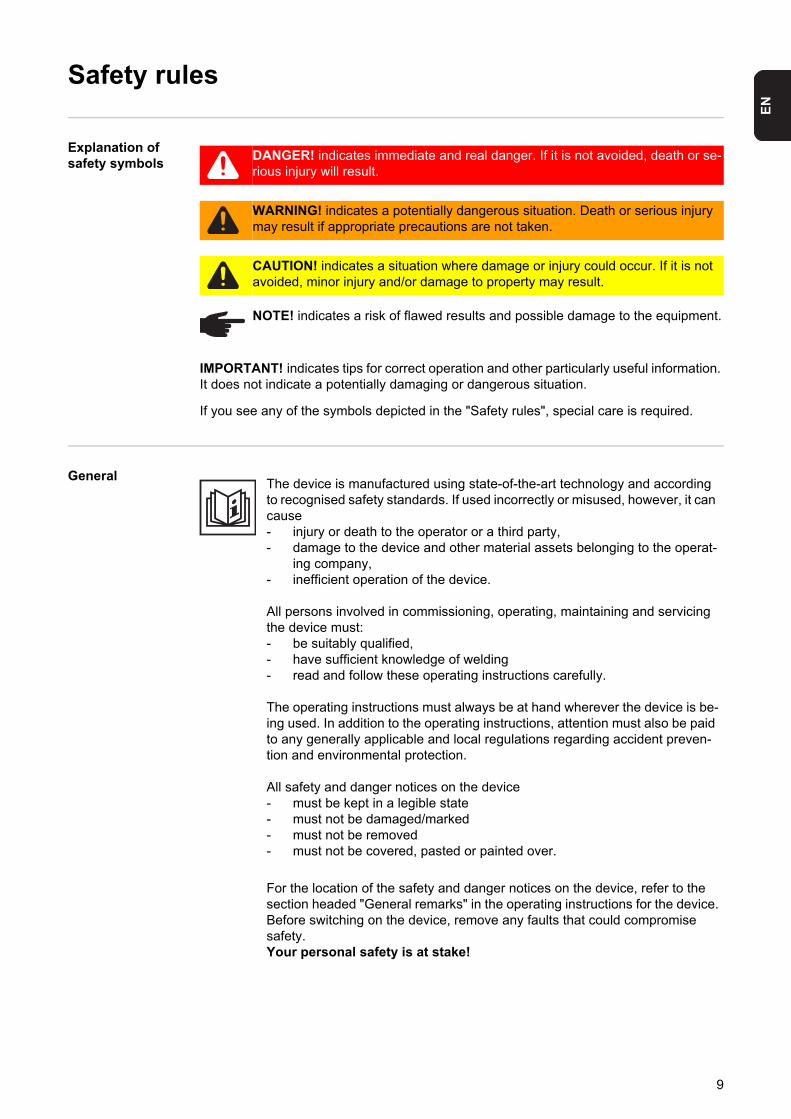
Explanation of safety symbols
If you see any of the symbols depicted in the "Safety rules", special care is required.
General
DANGER! indicates immediate and real danger. If it is not avoided, death or se-rious injury will result.
WARNING! indicates a potentially dangerous situation. Death or serious injury may result if appropriate precautions are not taken.
CAUTION! indicates a situation where damage or injury could occur. If it is not avoided, minor injury and/or damage to property may result.
NOTE! indicates a risk of flawed results and possible damage to the equipment.
IMPORTANT! indicates tips for correct operation and other particularly useful information. It does not indicate a potentially damaging or dangerous situation.
The device is manufactured using state-of-the-art technology and according to recognised safety standards. If used incorrectly or misused, however, it can cause- injury or death to the operator or a third party,- damage to the device and other material assets belonging to the operat-
ing company,- inefficient operation of the device.
All persons involved in commissioning, operating, maintaining and servicing the device must:- be suitably qualified,- have sufficient knowledge of welding- read and follow these operating instructions carefully.
The operating instructions must always be at hand wherever the device is be-ing used. In addition to the operating instructions, attention must also be paid to any generally applicable and local regulations regarding accident preven-tion and environmental protection.
All safety and danger notices on the device - must be kept in a legible state - must not be damaged/marked - must not be removed- must not be covered, pasted or painted over.
For the location of the safety and danger notices on the device, refer to the section headed "General remarks" in the operating instructions for the device.Before switching on the device, remove any faults that could compromise safety.Your personal safety is at stake!
9
Intended purpose
Environmental conditions
Obligations of the operator
The device is to be used exclusively for its intended purpose.
The device is intended for the welding process described on the rating plate only. Any use above and beyond this purpose is deemed improper. The manufac-turer shall not be liable for any damage resulting from such improper use.
Utilisation in accordance with the "intended purpose" also comprises- reading carefully and following all operating instructions to the letter - studying and obeying all safety and danger notices carefully- performing all stipulated inspection and servicing work.
Never use the device for the following purposes:- Thawing out pipes- Charging batteries/accumulators- Starting engines
The device is designed for use in industry and the workshop. The manufactur-er accepts no responsibility for any damage caused through use in a domestic setting.
The manufacturer likewise accepts no liability for unexpected or incorrect re-sults.
Operation or storage of the device outside the stipulated area will be deemed as "not in accordance with the intended purpose". The manufacturer shall not be liable for any damage resulting from such improper use.
Ambient temperature:- during operation: -10 °C to + 40 °C (14 °F to 104 °F)- during transport and storage: -25 °C to +55 °C (-13 °F to 131 °F)
Relative humidity:- up to 50 % at 40 °C (104 °F)- up to 90 % at 20 °C (68 °F)
Ambient air: free from dust, acids, corrosive gases and substances, etc.For use at altitudes above sea level: up to 2000 m (6500 ft)
The operator undertakes only to allow persons to work with the device who: - are familiar with the fundamental instructions regarding safety and acci-
dent prevention, and have been instructed how to use the device- have read and understood these operating instructions, especially the
section “safety rules”, and have confirmed as much with their signatures - are trained to produce the required results.
Checks must be carried out at regular intervals to ensure that operators are working in a safety-conscious manner.
10
EN
Obligations ofpersonnel
Mains connection
Protecting your-self and others
Before using the device, all persons instructed to do so undertake:- to observe the basic instructions regarding safety at work and accident
prevention- to read these operating instructions, especially the "Safety rules" section
and sign to confirm that they have understood them and will follow them.
Before leaving the work area, ensure that people or property cannot come to any harm in your absence.
Devices with a higher rating may affect the energy quality of the mains due to their current input.
This may affect a number of types of device in terms of:- connection restrictions- criteria with regard to maximum permissible mains impedance *)
- criteria with regard to minimum short-circuit power requirement *)
*)at the interface with the public mains network
see Technical Data
In this case, the plant operator or the person using the device should check whether the device may be connected, where appropriate by discussing the matter with the power supply company.
Persons involved with welding expose themselves to numerous risks, e.g.:- flying sparks and hot pieces of metal- arc radiation, which can damage eyes and skin
- hazardous electromagnetic fields, which can endanger the lives of those using cardiac pacemakers
- risk of electrocution from mains current and welding current
- greater noise pollution
- harmful welding fumes and gases
Anyone working on the workpiece while welding is in progress must wear suit-able protective clothing with the following properties:- flame-resistant- insulating and dry- covers the whole body, is undamaged and in good condition- safety helmet- trousers with no turn-ups
Protective clothing refers to a variety of different items. Operators should:
11
Noise emission values
Danger from toxic gases and va-pours
- protect eyes and face from UV rays, heat and sparks using a protective visor and regulation filter.
- wear regulation protective goggles with side protection behind the safety visor.
- wear stout footwear that provides insulation even in wet conditions.- protect the hands with suitable gloves (electrically insulated and providing
protection against heat).- wear ear protection to reduce the harmful effects of noise and to prevent
injury.
Keep all persons, especially children, out of the working area while any devic-es are in operation or welding is in progress. If, however, there are people in the vicinity,- make them aware of all the dangers (risk of dazzling by the arc, injury
from flying sparks, harmful welding fumes, noise, possible danger from mains or welding current, etc.),
- provide suitable protective equipment or- erect suitable safety screens/curtains.
The device generates a maximum sound power level of <80 dB(A) (ref. 1pW) when idling and in the cooling phase following operation at the maximum per-missible operating point under maximum rated load conditions according to EN 60974-1.
It is not possible to provide a workplace-related emission value during welding (or cutting) as this is influenced by both the process and the environment. All manner of different welding parameters come into play, including the welding process (MIG/MAG, TIG welding), the type of power selected (DC or AC), the power range, the type of weld metal, the resonance characteristics of the workpiece, the workplace environment, etc.
The fumes produced during welding contain harmful gases and vapours.
Welding fumes contain substances that may, under certain circumstances, cause birth defects or cancer.
Keep your face away from welding fumes and gases.
Fumes and hazardous gases,- must not be breathed in- must be extracted from the working area using appropriate methods.
Ensure an adequate supply of fresh air.
If this cannot be provided, a protective mask with an air supply must be worn.
Close the shielding gas cylinder valve or central gas supply if no welding is tak-ing place.
12
EN
Danger from fly-ing sparks
Risks from mains current and weld-ing current
If there is any doubt about whether the extraction system is powerful enough, then the measured toxic emission values should be compared with the permis-sible limit values.
The following components are responsible, amongst other things, for the de-gree of toxicity of welding fumes:- Metals used for the workpiece- Electrodes- Coatings- Cleaners, degreasers, etc.
The relevant material safety data sheets and manufacturer's specifications for the listed components should therefore be studied carefully.
Flammable vapours (e.g. solvent fumes) should be kept away from the arc's radiation area.
Flying sparks may cause fires or explosions.
Never weld close to flammable materials.
Flammable materials must be at least 11 metres (35 ft) away from the arc, or alternatively covered with an approved cover.
A suitable, tested fire extinguisher must be available and ready for use.
Sparks and pieces of hot metal may also get into adjacent areas through small gaps or openings. Take appropriate precautions to prevent any danger of in-jury or fire.
Welding must not be performed in areas that are subject to fire or explosion or near sealed tanks, vessels or pipes unless these have been prepared in ac-cordance with the relevant national and international standards.
Do not carry out welding on containers that are being or have been used to store gases, propellants, mineral oils or similar products. Residues pose an explosive hazard.
An electric shock is life threatening and can be fatal.
Do not touch live parts either inside or outside the device.
During MIG/MAG or TIG welding, the welding wire, the wirespool, the drive rollers and all metal parts that are in contact with the welding wire are live.
Always set the wire-feed unit up on a sufficiently insulated surface or use a suitable, insulated wire-feed unit mount.
Make sure that you and others are protected with an adequately insulated, dry temporary backing or cover for the earth or ground potential. This temporary backing or cover must extend over the entire area between the body and the earth or ground potential.
13

All cables and leads must be complete, undamaged, insulated and adequately dimensioned. Loose connections, scorched, damaged or inadequately dimen-sioned cables and leads must be repaired/replaced immediately.
Do not sling cables or leads around either the body or parts of the body.
The electrode (rod electrode, tungsten electrode, welding wire, etc) must- never be immersed in liquid for cooling- never be touched when current is flowing.
Double the open circuit voltage of a welding machine can occur between the welding electrodes of two welding machines. Touching the potentials of both electrodes at the same time may under certain circumstances be fatal.
Arrange for the mains and device supply to be checked regularly by a qualified electrician to ensure the PE conductor is functioning properly.
The device must only be operated on a mains supply with a PE conductor and a socket with an earth contact.
If the device is operated on a mains without a PE conductor and in a socket without an earth contact, this will be deemed gross negligence. The manufac-turer shall not be liable for any damage resulting from such improper use.
If necessary, provide an adequate earth connection for the workpiece.
Switch off unused devices.
Wear a safety harness if working at height.
Before working on the device, switch it off and pull out the mains plug.
Attach a clearly legible and easy-to-understand warning sign to the device to prevent anyone from reconnecting it to the mains and switching it on again.
After opening the device:- discharge all components holding an electric charge- ensure that all components in the device are de-energised.
If work on live parts cannot be avoided, appoint a second person to switch off the main switch at the right moment.
14
EN
Meandering weld-ing currents
EMC device clas-sifications
EMC measures
If the following instructions are ignored, meandering welding currents can de-velop with the following consequences:- Fire hazard- Overheating of parts connected to the workpiece- Irreparable damage to PE conductors- Damage to device and other electrical equipment
Ensure that the workpiece is held securely by the workpiece clamp.
Attach the workpiece clamp as close as possible to the area that is to be weld-ed.
If the floor is electrically conductive, the device must be set up with sufficient insulating material to insulate it from the floor.
If distribution boards, twin-head mounts, etc., are being used, note the follow-ing: The electrode of the welding torch / electrode holder that is not used is also live. Make sure that the welding torch / electrode holder that is not used is kept sufficiently insulated.
In the case of automated MIG/MAG applications, ensure that only an insulated wire electrode is routed from the welding wire drum, large wirefeeder spool or wirespool to the wire-feed unit.
Devices with emission class A:- are only designed for use in an industrial setting- can cause conducted and emitted interference in other areas.
Devices with emission class B:- satisfy the emissions criteria for residential and industrial areas.
This also applies to residential areas in which power is supplied from the public low-voltage grid.
EMC device classification according to the rating plate or the techni-cal data.
In certain cases, even though a device complies with the standard limit values for emissions, it may affect the application area for which it was designed (e.g. when there is sensitive equipment at the same location, or if the site where the device is installed is close to either radio or television receivers).If this is the case, then the operator is obliged to take appropriate action to rec-tify the situation.
15
EMF measures
Specific hazards
Check for possible problems, and check and evaluate neighbouring devices' resistance to interference according to national and international require-ments:- Safety features- power, signal and data transfer lines- IT and telecommunications devices- measuring and calibrating devices
Supporting measures for avoidance of EMC problems:a) Mains supply
- if electromagnetic interference arises despite correct mains connec-tion, additional measures are necessary (e.g. use a suitable line fil-ter).
b) Welding leads- must be kept as short as possible- must run close together (to avoid EMF problems)- must be kept well apart from other leads
c) Equipotential bondingd) Earthing the workpiece
- if necessary, establish an earth connection using suitable capacitors.e) Shielding, if necessary
- shield off other nearby devices- shield off entire welding installation
Electromagnetic fields may pose as yet unknown risks to health:- effects on the health of others in the vicinity, e.g. wearers of pacemakers
and hearing aids- wearers of pacemakers must seek advice from their doctor before ap-
proaching the device or any welding that is in progress- for safety reasons, keep distances between the welding cables and the
welder's head/torso as large as possible- do not carry welding cables and hosepacks over the shoulders or wind
them around any part of the body
Keep hands, hair, clothing and tools away from moving parts. For example:- Fans- Cogs- Rollers- Shafts- Wirespools and welding wires
Do not reach into the rotating cogs of the wire drive or into rotating drive com-ponents.
Covers and side panels may only be opened/removed while maintenance or repair work is being carried out.
During operation- ensure that all covers are closed and all side panels are fitted properly.- keep all covers and side panels closed.
16
EN
The welding wire emerging from the welding torch poses a high risk of injury (piercing of the hand, injuries to the face and eyes, etc.).
Always keep the welding torch away from the body (devices with wire-feed unit) and wear suitable protective goggles.
Never touch the workpiece during or after welding - risk of burns.
Slag can jump off cooling workpieces. The specified protective equipment must therefore also be worn when reworking workpieces, and steps must be taken to ensure that other people are also adequately protected.
Welding torches and other parts with a high operating temperature must be al-lowed to cool down before handling.
Special provisions apply in areas at risk of fire or explosion - observe relevant national and international regulations.
Power sources that are to be used in areas with increased electric risk (e.g. near boilers) must carry the "Safety" sign. However, the power source must not be located in such areas.
Risk of scalding from escaping coolant. Switch off cooling unit before discon-necting coolant flow or return lines.
Use only suitable load-carrying equipment supplied by the manufacturer when transporting devices by crane.
- Hook chains and/or ropes onto the suspension points provided on the load-carrying equipment.
- Chains/ropes must be at the smallest angle possible to the vertical.- Remove gas cylinder and wire-feed unit (MIG/MAG and TIG devices).
If the wire-feed unit is attached to a crane holder during welding, always use a suitable, insulated wire-feed unit holder (MIG/MAG and TIG devices).
If the device has a carrying strap or handle, this is intended solely for carrying by hand. The carrying strap is not to be used if transporting with a crane, forklift truck or other mechanical hoist.
Odourless and colourless shielding gas may escape unnoticed if an adapter is used for the shielding gas connection. Prior to assembly, seal the device-side thread of the adapter for the shielding gas connection using suitable Te-flon tape.
17
Danger from shielding gas cyl-inders
Safety measures at the installation location and dur-ing transport
Shielding gas cylinders contain gas under pressure and can explode if dam-aged. As the shielding gas cylinders are part of the welding equipment, they must be handled with the greatest of care.
Protect shielding gas cylinders containing compressed gas from excessive heat, mechanical impact, slag, naked flames, sparks and arcs.
Mount the shielding gas cylinders vertically and secure according to instruc-tions to prevent them falling over.
Keep the shielding gas cylinders well away from any welding or other electrical circuits.
Never hang a welding torch on a shielding gas cylinder.
Never touch a shielding gas cylinder with an electrode.
Risk of explosion - never attempt to weld a pressurised shielding gas cylinder.
Only use shielding gas cylinders suitable for the application in hand, along with the correct and appropriate accessories (regulator, hoses and fittings). Only use shielding gas cylinders and accessories that are in good condition.
Turn your face to one side when opening the valve of a shielding gas cylinder.
Close the shielding gas cylinder valve if no welding is taking place.
If the shielding gas cylinder is not connected, leave the valve cap in place on the cylinder.
The manufacturer's instructions must be observed as well as applicable na-tional and international regulations for shielding gas cylinders and accesso-ries.
A device that topples over can easily kill someone. Place the device on a solid, level surface in such a way that it remains stable- The maximum permissible slope is 10°.
Special regulations apply in rooms at risk of fire or explosion- observe relevant national and international requirements.
Use internal directives and checks to ensure that the workplace environment is always clean and clearly laid out.
Only set up and operate the device in accordance with the degree of protec-tion shown on the rating plate.
When setting up the device, ensure there is a gap of 0.5 m (1 ft. 7.69 in.) all round so that cooling air can enter and exit unhindered.
18
EN
Safety measures in normal opera-tion
When transporting the device, observe the relevant national and local guide-lines and accident prevention regulations. This applies especially to guidelines regarding the risks arising during transportation.
Before transporting the device, allow coolant to drain completely and detach the following components:- Wire-feed unit- Wirespool- Shielding gas cylinder
After transporting the device, and before commissioning, you MUST carry out a visual inspection to check whether it has been damaged in any way. Any damage must be repaired by trained service technicians before commission-ing takes place.
Only operate the device when all protection devices are fully functional. If the protection devices are not fully functional, there is a risk of- injury or death to the operator or a third party,- damage to the device and other material assets belonging to the operator,- inefficient operation of the device.
Any safety devices that are not functioning properly must be repaired before switching on the device.
Never bypass or disable protection devices.
Before switching on the device, ensure that no one is likely to be endangered.
- Check the device at least once a week for obvious damage and proper functioning of safety devices.
- Always fasten the shielding gas cylinder securely and remove it before-hand if the device is to be transported by crane.
- Only the manufacturer's original coolant is suitable for use with our devic-es due to its properties (electrical conductivity, frost protection, material compatibility, flammability, etc.)
- Only use suitable original coolant from the manufacturer.- Do not mix the manufacturer's original coolant with other coolants.- If damage results from using a different coolant, the manufacturer accepts
no liability. In addition, no warranty claims will be entertained.- The coolant can ignite under certain conditions. Transport the coolant
only in its original, sealed containers and keep well away from any sourc-es of ignition
- Used coolant must be disposed of properly in accordance with the rele-vant national and international regulations. A safety data sheet may be obtained from your service centre or downloaded from the manufacturer's website.
- Check the coolant level before you start to weld while the system is still cool.
19
Maintenance and repair
Safety inspection
Disposal
Safety symbols
It is impossible to guarantee that bought-in parts are designed and manufac-tured to meet the demands made on them, or that they satisfy safety require-ments. Use only original replacement and wearing parts (also applies to standard parts).Do not carry out any modifications, alterations, etc. to the device without the manufacturer's consent.Components that are not in perfect condition must be changed immediately.When ordering, please give the exact designation and part number as shown in the spare parts list, as well as the serial number of your device.
The manufacturer recommends that a safety inspection of the device is per-formed at least once every 12 months.
The manufacturer recommends that the power source be calibrated during the same 12-month period.
A safety inspection should be carried out by a qualified electrician- after any changes are made- after any additional parts are installed, or after any conversions- after repair, care and maintenance has been carried out- at least every twelve months.
For safety inspections, follow the appropriate national and international stand-ards and directives.
Further details on safety inspection and calibration can be obtained from your service centre. They will provide you on request with any documents you may require.
Do not dispose of this device with normal domestic waste! To comply with the European Directive 2002/96/EC on Waste Electrical and Electronic Equip-ment and its implementation as national law, electrical equipment that has reached the end of its life must be collected separately and returned to an ap-proved recycling facility. Any device that you no longer require must either be returned to your dealer or given to one of the approved collection and recycling facilities in your area. Ignoring this European Directive may have potentially adverse affects on the environment and your health!
Devices with the CE marking satisfy the essential requirements of the low-volt-age and electromagnetic compatibility directive (e.g. relevant product norms from the EN 60 974 series).
Devices with the CSA test mark satisfy the requirements of the relevant stand-ards in Canada and the USA.
20

EN
Data protectionCopyright
The user is responsible for the safekeeping of any changes made to the fac-tory settings. The manufacturer accepts no liability for any deleted personal settings.
Copyright of these operating instructions remains with the manufacturer.
The text and illustrations are all technically correct at the time of printing. We reserve the right to make changes. The contents of the operating instructions shall not provide the basis for any claims whatsoever on the part of the pur-chaser. If you have any suggestions for improvement, or can point out any mistakes that you have found in the instructions, we will be most grateful for your comments.
21

22

General information

EN
General
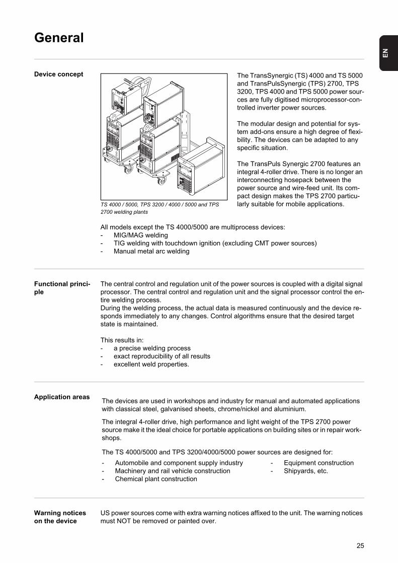
Device concept
TS 4000 / 5000, TPS 3200 / 4000 / 5000 and TPS 2700 welding plants
The TransSynergic (TS) 4000 and TS 5000 and TransPulsSynergic (TPS) 2700, TPS 3200, TPS 4000 and TPS 5000 power sour-ces are fully digitised microprocessor-con-trolled inverter power sources.
The modular design and potential for sys-tem add-ons ensure a high degree of flexi-bility. The devices can be adapted to any specific situation.
The TransPuls Synergic 2700 features an integral 4-roller drive. There is no longer an interconnecting hosepack between the power source and wire-feed unit. Its com-pact design makes the TPS 2700 particu-larly suitable for mobile applications.
All models except the TS 4000/5000 are multiprocess devices:- MIG/MAG welding- TIG welding with touchdown ignition (excluding CMT power sources)- Manual metal arc welding
Functional princi-ple
The central control and regulation unit of the power sources is coupled with a digital signal processor. The central control and regulation unit and the signal processor control the en-tire welding process.During the welding process, the actual data is measured continuously and the device re-sponds immediately to any changes. Control algorithms ensure that the desired target state is maintained.
This results in:- a precise welding process- exact reproducibility of all results- excellent weld properties.
Application areas
Warning notices on the device
US power sources come with extra warning notices affixed to the unit. The warning notices must NOT be removed or painted over.
VR 7000
The devices are used in workshops and industry for manual and automated applications with classical steel, galvanised sheets, chrome/nickel and aluminium.
The integral 4-roller drive, high performance and light weight of the TPS 2700 power source make it the ideal choice for portable applications on building sites or in repair work-shops.
The TS 4000/5000 and TPS 3200/4000/5000 power sources are designed for:
- Automobile and component supply industry- Machinery and rail vehicle construction- Chemical plant construction
- Equipment construction- Shipyards, etc.
25
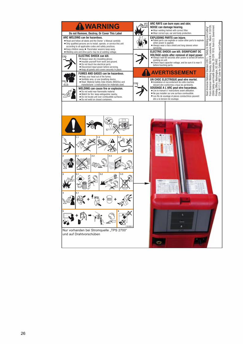
Nur vorhanden bei Stromquelle „TPS 2700“und auf Drahtvorschüben
26
EN
Special versions
General Professional processing of specific materials requires welding programs that are specially matched to the different materials in question. The special versions of the digital power sources are perfectly matched to these requirements. As a result the most important weld-ing programs can be called up directly from the operating panel. Furthermore, the power sources are characterised by standard functions that assist the user when welding these materials.
Alu edition The Alu edition power sources were developed for perfect and careful processing of alu-minium. Special aluminium welding programs assist in the professional processing of alu-minium.The Alu edition power sources are equipped as standard with the following options:- Special aluminium welding programs- SynchroPulse option
CrNi edition The CrNi edition power sources were developed for perfect and careful processing of CrNi. Special CrNi welding programs assist in the professional processing of high-grade steels. The CrNi edition power sources are equipped as standard with the following options:- Special CrNi welding programs- SynchroPulse option- TIG Comfort Stop option- TIG welding torch connection- Gas solenoid valve
CMT Variants In addition to conventional welding processes, the CMT variants also support the CMT process. CMT (Cold Metal Transfer) is a special MIG short-arc process. Its special features include low heat input and a controlled, low-current material transfer.CMT is suitable for:- Virtually spatter-free MIG brazing- Welding on light-gauge sheet with minimal distortion- Joining steel and aluminium (weld brazing)
CMT 4000 Ad-vanced
In addition to the conventional MIG/MAG welding processes, MMA welding and the CMT process, the CMT 4000 Advanced power source supports the improved CMT Advanced process.The functional principle of the CMT Advanced process is based on a combination arc with negatively polarised CMT cycles and positively polarised CMT cycles or positively polar-
NOTE! The technical data of the special versions is identical to that of the stand-ard power sources.
NOTE! It is not possible to install the “Uni Box” system add-on on the CrNi edition (e.g. for the field bus connection of a robot control).However, the CrNi edition supports a robot connection via ROB 4000 / 5000 robot interfaces.
27
ised pulse cycles. Special features are targeted heat input, a higher deposition rate, better gap bridging properties, precise droplet detachment and an extremely stable arc.CMT Advanced is suitable for:- joining thin sheets with outstanding gap bridging properties- High-strength steels with low heat input- Spots: precisely defined drop volumes and defined heat input- Root passes with no pool support- Brazing high-strength and ultra high-strength steels
TIME 5000 Digital ConceptAs a universal power source, the TIME 5000 Digital is particularly suited for manual appli-cations. In addition to conventional welding processes, the TIME 5000 Digital also sup-ports the TIME high-performance welding process.
Functional principleCompared with conventional MIG/MAG processes, the following features bring about fast-er welding speeds, with an increase in deposition rate of up to 30%:- Power module with high voltage reserves- High performance welding programs- Specially selected shielding gases- High-performance wire-feed unit with water-cooled disc armature motor for wire feed
speeds of up to 30 m/min- TIME welding torch with dual circuit cooling system
ApplicationAnywhere where long weld seams, large seam cross-sections and controlled heat input are required, e.g.:- Mechanical engineering- Steel engineering- Crane construction- Shipbuilding- Boiler manufacture
The new TIME 5000 Digital power source can also be used in automated applications.
Material typesThe high-performance welding process is especially suitable for- unalloyed steels- low-alloy steels EN 10027- fine-grained structural steels up to 890 N/mm²- steels resistant to low temperatures
Yard edition Yard edition power sources are designed especially for use in shipyards and offshore ap-plications. The welding programs are designed primarily for steel and CrNi applications with solid and flux cored wires.
Steel edition Steel edition power sources are designed specifically for use in the steel sector. The spe-cial characteristics can be set on the control panel - both for standard and pulsed arcs.
28
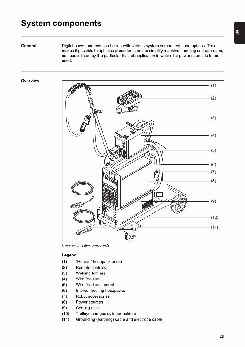
EN
System components
General Digital power sources can be run with various system components and options. This makes it possible to optimise procedures and to simplify machine handling and operation, as necessitated by the particular field of application in which the power source is to be used.
Overview
Overview of system components
Legend:
(1) “Human” hosepack boom
(2) Remote controls
(3) Welding torches
(4) Wire-feed units
(5) Wire-feed unit mount
(6) Interconnecting hosepacks
(7) Robot accessories
(8) Power sources
(9) Cooling units
(10) Trolleys and gas cylinder holders
(11) Grounding (earthing) cable and electrode cable
(1)
(2)
(3)
(4)
(5)
(6)
(7)
(11)
(10)
(9)
(8)
FRONIUS
29

30

Control elements and connections

EN
Description of the control panels
General The functions on the control panels are all arranged in a logical way. The various welding parameters can easily be selected using buttons and can just as easily be- altered using buttons or the adjusting dial- displayed on the digital display during welding
The synergic function ensures that all other welding parameters are adjusted when an in-dividual parameter has been changed.
Safety
Overview "Description of the control panels" is composed of the following sections:- Standard control panel- Comfort control panel- US control panel- TIME 5000 Digital control panel- CMT control panel- Yard control panel- Remote control panel- CMT Remote control panel - CrNi control panel- Steel control panel
NOTE! As a result of software updates, you may find that your device has certain functions that are not described in these operating instructions, or vice versa. Cer-tain illustrations may also differ slightly from the actual control elements on your device, but these controls function in exactly the same way.
WARNING! Operating the equipment incorrectly can cause serious injury and damage. Do not use the functions described until you have thoroughly read and understood the following documents:- these operating instructions- all the operating instructions for the system components, especially the safe-
ty rules
33
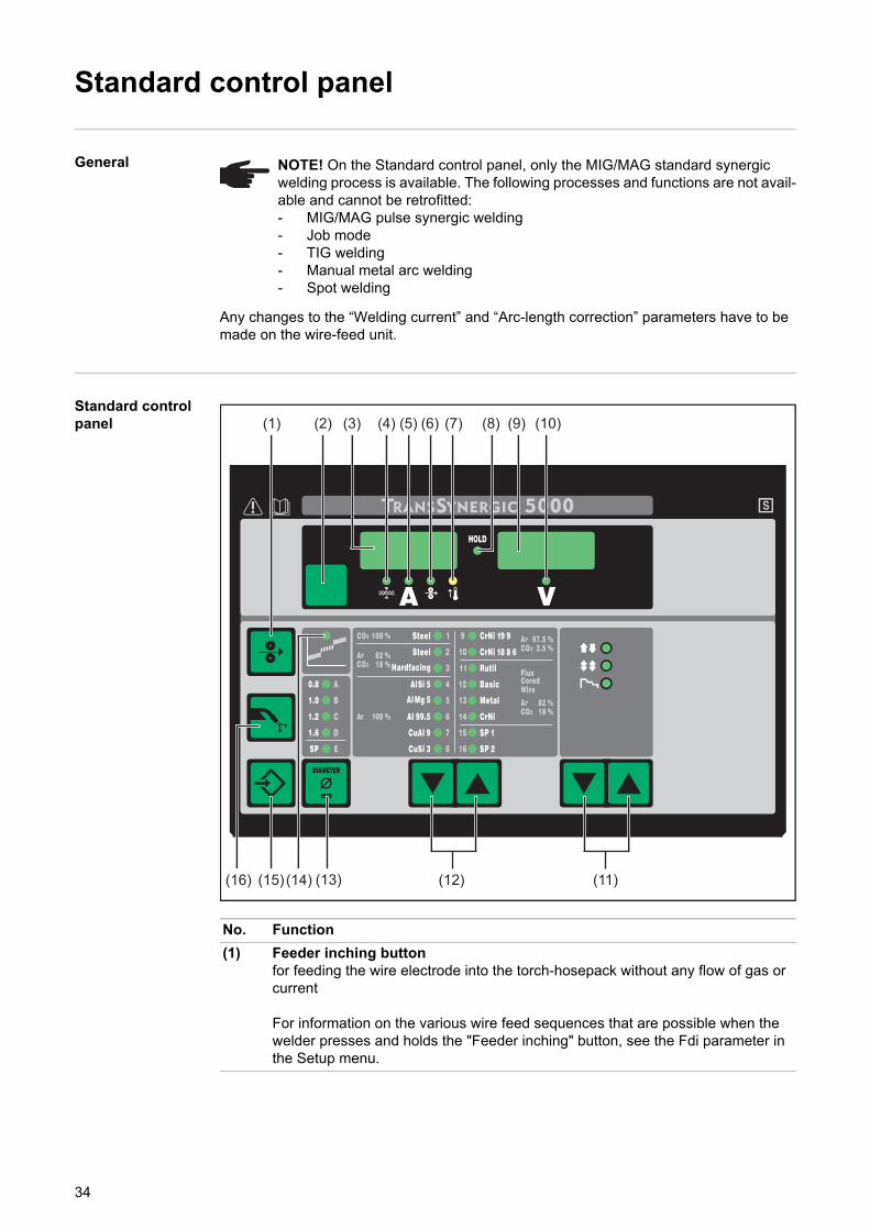
Standard control panel
General
Any changes to the “Welding current” and “Arc-length correction” parameters have to be made on the wire-feed unit.
Standard control panel
NOTE! On the Standard control panel, only the MIG/MAG standard synergic welding process is available. The following processes and functions are not avail-able and cannot be retrofitted:- MIG/MAG pulse synergic welding- Job mode- TIG welding- Manual metal arc welding- Spot welding
No. Function
(1) Feeder inching buttonfor feeding the wire electrode into the torch-hosepack without any flow of gas or current
For information on the various wire feed sequences that are possible when the welder presses and holds the "Feeder inching" button, see the Fdi parameter in the Setup menu.
(3) (5)
(15) (14)
(6) (9) (10)(8)(7)(4)
(13) (12) (11)
(2)(1)
(16)
34
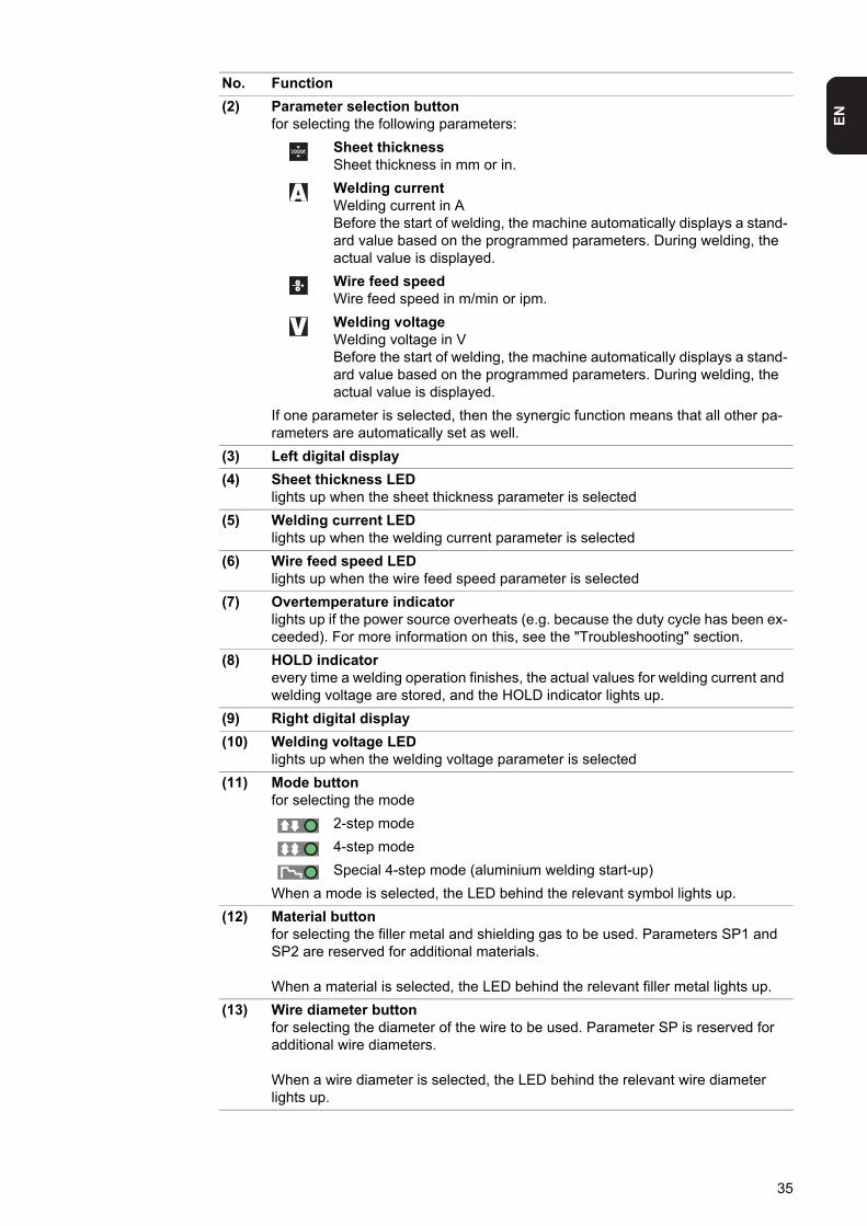
EN
(2) Parameter selection buttonfor selecting the following parameters:
Sheet thicknessSheet thickness in mm or in.
Welding currentWelding current in ABefore the start of welding, the machine automatically displays a stand-ard value based on the programmed parameters. During welding, the actual value is displayed.
Wire feed speedWire feed speed in m/min or ipm.
Welding voltageWelding voltage in VBefore the start of welding, the machine automatically displays a stand-ard value based on the programmed parameters. During welding, the actual value is displayed.
If one parameter is selected, then the synergic function means that all other pa-rameters are automatically set as well.
(3) Left digital display
(4) Sheet thickness LEDlights up when the sheet thickness parameter is selected
(5) Welding current LEDlights up when the welding current parameter is selected
(6) Wire feed speed LEDlights up when the wire feed speed parameter is selected
(7) Overtemperature indicatorlights up if the power source overheats (e.g. because the duty cycle has been ex-ceeded). For more information on this, see the "Troubleshooting" section.
(8) HOLD indicatorevery time a welding operation finishes, the actual values for welding current and welding voltage are stored, and the HOLD indicator lights up.
(9) Right digital display
(10) Welding voltage LEDlights up when the welding voltage parameter is selected
(11) Mode buttonfor selecting the mode
2-step mode
4-step mode
Special 4-step mode (aluminium welding start-up)
When a mode is selected, the LED behind the relevant symbol lights up.
(12) Material buttonfor selecting the filler metal and shielding gas to be used. Parameters SP1 and SP2 are reserved for additional materials.
When a material is selected, the LED behind the relevant filler metal lights up.
(13) Wire diameter buttonfor selecting the diameter of the wire to be used. Parameter SP is reserved for additional wire diameters.
When a wire diameter is selected, the LED behind the relevant wire diameter lights up.
No. Function
35
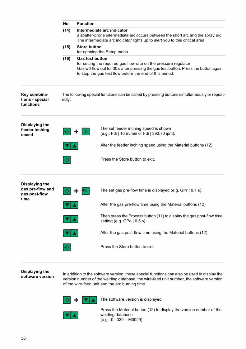
Key combina-tions - special functions
The following special functions can be called by pressing buttons simultaneously or repeat-edly.
Displaying the feeder inching speed
Displaying the gas pre-flow and gas post-flow time
Displaying the software version
(14) Intermediate arc indicatora spatter-prone intermediate arc occurs between the short arc and the spray arc. The intermediate arc indicator lights up to alert you to this critical area
(15) Store buttonfor opening the Setup menu
(16) Gas test buttonfor setting the required gas flow rate on the pressure regulator.Gas will flow out for 30 s after pressing the gas test button. Press the button again to stop the gas test flow before the end of this period.
No. Function
The set feeder inching speed is shown(e.g.: Fdi | 10 m/min or Fdi | 393.70 ipm).
Alter the feeder inching speed using the Material buttons (12)
Press the Store button to exit.
The set gas pre-flow time is displayed (e.g. GPr | 0.1 s).
Alter the gas pre-flow time using the Material buttons (12)
Then press the Process button (11) to display the gas post-flow time setting (e.g. GPo | 0.5 s)
Alter the gas post-flow time using the Material buttons (12)
Press the Store button to exit.
In addition to the software version, these special functions can also be used to display the version number of the welding database, the wire-feed unit number, the software version of the wire-feed unit and the arc burning time.
The software version is displayed
Press the Material button (12) to display the version number of the welding database(e.g.: 0 | 029 = M0029).
36

EN
Press the Material button (12) again to display the number of the wire-feed unit (A or B in the case of twin-head mounts) and the soft-ware version of the wire-feed unit(e.g.: A 1.5 | 0.23).
Press the Material button (12) a third time to display the actual arc burning time since starting for the first time (e.g. "654 | 32.1" = 65,432.1 h = 65,432 h, 6 min)
NOTE! The arc burning time indicator is not suitable as a basis for calculating hiring fees, guarantee, etc.
Press the Store button to exit.
37
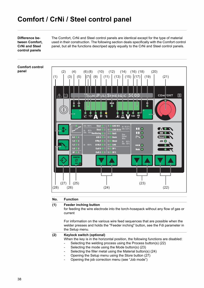
Comfort / CrNi / Steel control panel
Difference be-tween Comfort, CrNi and Steel control panels
The Comfort, CrNi and Steel control panels are identical except for the type of material used in their construction. The following section deals specifically with the Comfort control panel, but all the functions descriped apply equally to the CrNi and Steel control panels.
Comfort control panel
No. Function
(1) Feeder inching buttonfor feeding the wire electrode into the torch-hosepack without any flow of gas or current
For information on the various wire feed sequences that are possible when the welder presses and holds the "Feeder inching" button, see the Fdi parameter in the Setup menu.
(2) Keylock switch (optional)When the key is in the horizontal position, the following functions are disabled:- Selecting the welding process using the Process button(s) (22)- Selecting the mode using the Mode button(s) (23)- Selecting the filler metal using the Material button(s) (24)- Opening the Setup menu using the Store button (27)- Opening the job correction menu (see “Job mode”)
(14)(4)(1)
(28) (26)(25)
(5)(18)
(15)(12)
(11)(10)
(3)(6)
(9)(7)(16)(8)
(27)(24)
(23)(22)
(13)(2)
(19)(17)(20)
(21)
38
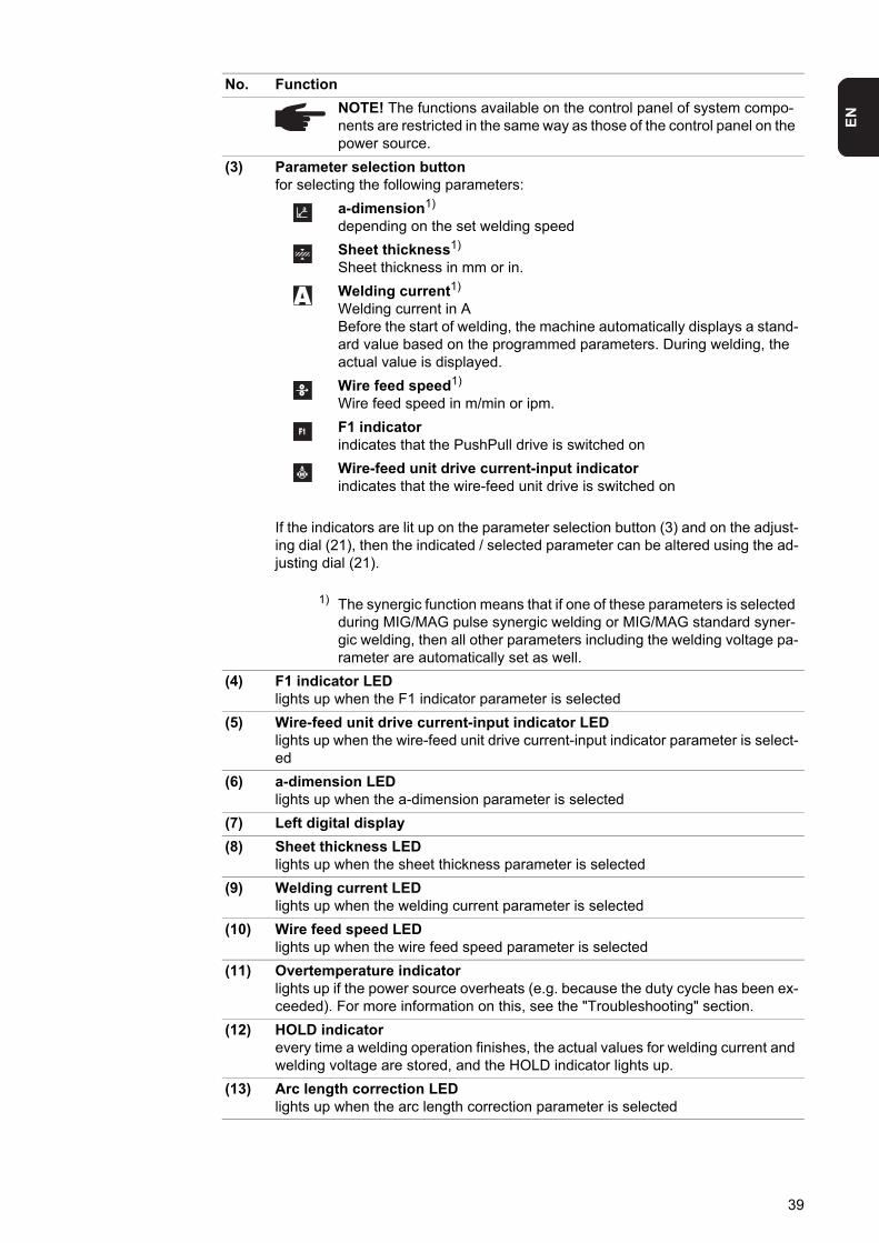
EN
NOTE! The functions available on the control panel of system compo-nents are restricted in the same way as those of the control panel on the power source.
(3) Parameter selection buttonfor selecting the following parameters:
a-dimension1)
depending on the set welding speed
Sheet thickness1)
Sheet thickness in mm or in.
Welding current1)
Welding current in ABefore the start of welding, the machine automatically displays a stand-ard value based on the programmed parameters. During welding, the actual value is displayed.
Wire feed speed1)
Wire feed speed in m/min or ipm.
F1 indicatorindicates that the PushPull drive is switched on
Wire-feed unit drive current-input indicatorindicates that the wire-feed unit drive is switched on
If the indicators are lit up on the parameter selection button (3) and on the adjust-ing dial (21), then the indicated / selected parameter can be altered using the ad-justing dial (21).
1) The synergic function means that if one of these parameters is selected during MIG/MAG pulse synergic welding or MIG/MAG standard syner-gic welding, then all other parameters including the welding voltage pa-rameter are automatically set as well.
(4) F1 indicator LEDlights up when the F1 indicator parameter is selected
(5) Wire-feed unit drive current-input indicator LEDlights up when the wire-feed unit drive current-input indicator parameter is select-ed
(6) a-dimension LEDlights up when the a-dimension parameter is selected
(7) Left digital display
(8) Sheet thickness LEDlights up when the sheet thickness parameter is selected
(9) Welding current LEDlights up when the welding current parameter is selected
(10) Wire feed speed LEDlights up when the wire feed speed parameter is selected
(11) Overtemperature indicatorlights up if the power source overheats (e.g. because the duty cycle has been ex-ceeded). For more information on this, see the "Troubleshooting" section.
(12) HOLD indicatorevery time a welding operation finishes, the actual values for welding current and welding voltage are stored, and the HOLD indicator lights up.
(13) Arc length correction LEDlights up when the arc length correction parameter is selected
No. Function
39
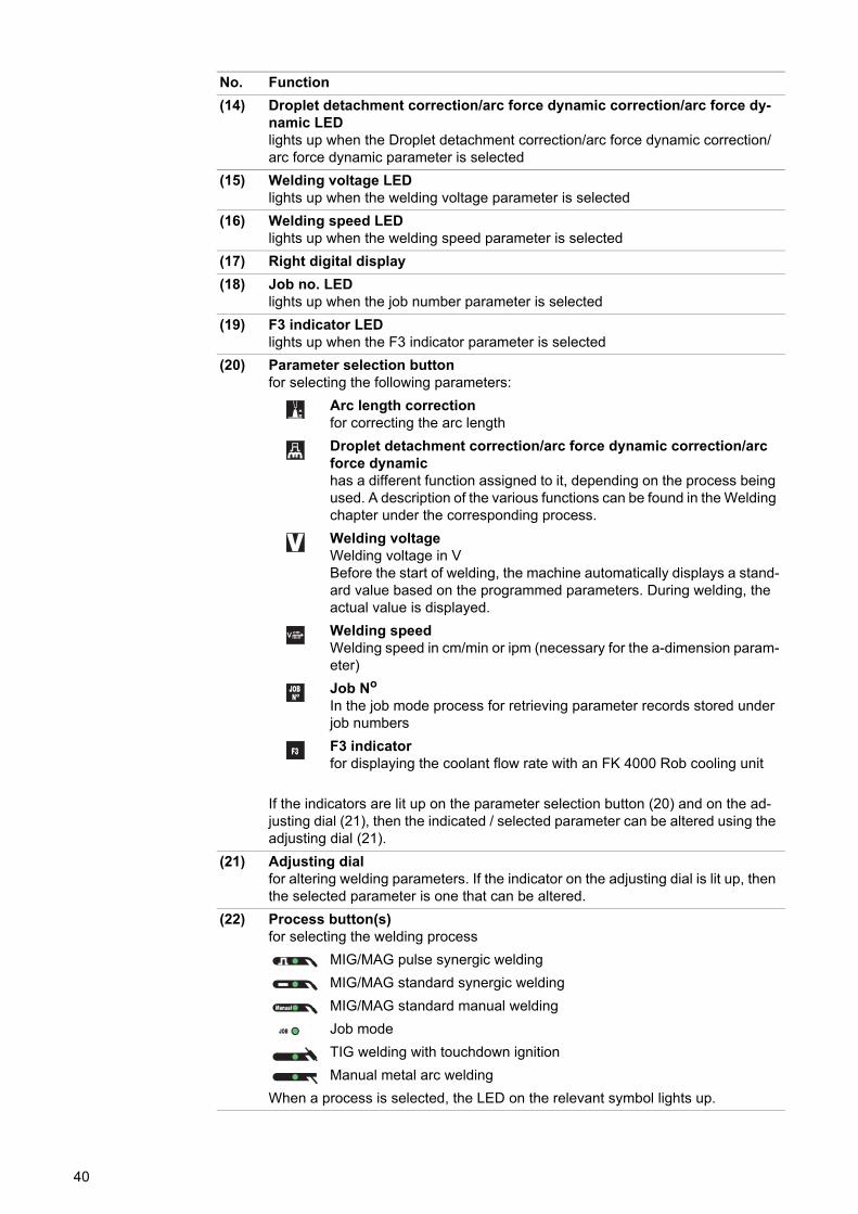
(14) Droplet detachment correction/arc force dynamic correction/arc force dy-namic LEDlights up when the Droplet detachment correction/arc force dynamic correction/arc force dynamic parameter is selected
(15) Welding voltage LEDlights up when the welding voltage parameter is selected
(16) Welding speed LEDlights up when the welding speed parameter is selected
(17) Right digital display
(18) Job no. LEDlights up when the job number parameter is selected
(19) F3 indicator LEDlights up when the F3 indicator parameter is selected
(20) Parameter selection buttonfor selecting the following parameters:
Arc length correctionfor correcting the arc length
Droplet detachment correction/arc force dynamic correction/arc force dynamichas a different function assigned to it, depending on the process being used. A description of the various functions can be found in the Welding chapter under the corresponding process.
Welding voltageWelding voltage in VBefore the start of welding, the machine automatically displays a stand-ard value based on the programmed parameters. During welding, the actual value is displayed.
Welding speedWelding speed in cm/min or ipm (necessary for the a-dimension param-eter)
Job No
In the job mode process for retrieving parameter records stored under job numbers
F3 indicatorfor displaying the coolant flow rate with an FK 4000 Rob cooling unit
If the indicators are lit up on the parameter selection button (20) and on the ad-justing dial (21), then the indicated / selected parameter can be altered using the adjusting dial (21).
(21) Adjusting dialfor altering welding parameters. If the indicator on the adjusting dial is lit up, then the selected parameter is one that can be altered.
(22) Process button(s)for selecting the welding process
MIG/MAG pulse synergic welding
MIG/MAG standard synergic welding
MIG/MAG standard manual welding
Job mode
TIG welding with touchdown ignition
Manual metal arc welding
When a process is selected, the LED on the relevant symbol lights up.
No. Function
40
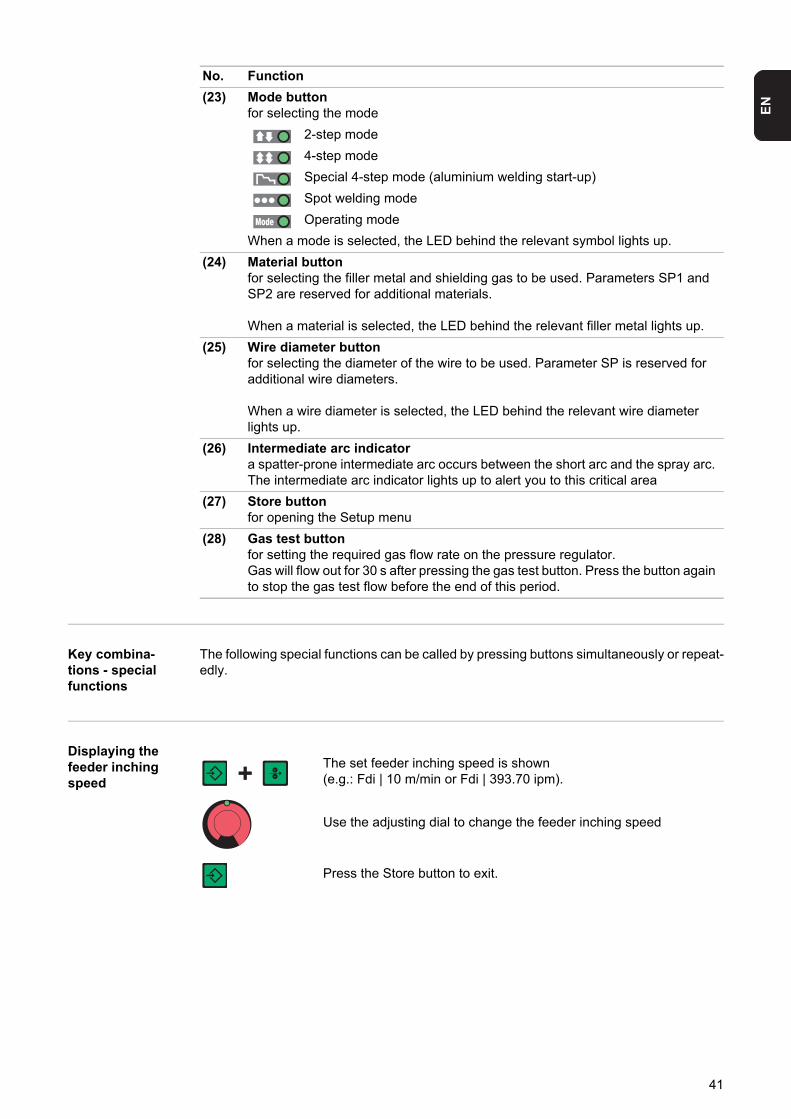
EN
Key combina-tions - special functions
The following special functions can be called by pressing buttons simultaneously or repeat-edly.
Displaying the feeder inching speed
(23) Mode buttonfor selecting the mode
2-step mode
4-step mode
Special 4-step mode (aluminium welding start-up)
Spot welding mode
Operating mode
When a mode is selected, the LED behind the relevant symbol lights up.
(24) Material buttonfor selecting the filler metal and shielding gas to be used. Parameters SP1 and SP2 are reserved for additional materials.
When a material is selected, the LED behind the relevant filler metal lights up.
(25) Wire diameter buttonfor selecting the diameter of the wire to be used. Parameter SP is reserved for additional wire diameters.
When a wire diameter is selected, the LED behind the relevant wire diameter lights up.
(26) Intermediate arc indicatora spatter-prone intermediate arc occurs between the short arc and the spray arc. The intermediate arc indicator lights up to alert you to this critical area
(27) Store buttonfor opening the Setup menu
(28) Gas test buttonfor setting the required gas flow rate on the pressure regulator.Gas will flow out for 30 s after pressing the gas test button. Press the button again to stop the gas test flow before the end of this period.
No. Function
The set feeder inching speed is shown(e.g.: Fdi | 10 m/min or Fdi | 393.70 ipm).
Use the adjusting dial to change the feeder inching speed
Press the Store button to exit.
41

Displaying the gas pre-flow and gas post-flow time
Displaying the software version
In addition to the software version, these special functions can also be used to display the version number of the welding database, the wire-feed unit number, the software version of the wire-feed unit and the arc burning time.
The set gas pre-flow time is displayed (e.g. GPr | 0.1 s)
Use the adjusting dial to change the gas pre-flow time
Then press the Process button (22) to display the gas post-flow time setting (e.g. GPo | 0.5 s)
Use the adjusting dial to change the gas post-flow time
Press the Store button to exit.
The software version is displayed
Press the Material button (24) to display the version number of the welding database(e.g.: 0 | 029 = M0029).
Press the Material button (24) again to display the number of the wire-feed unit (A or B in the case of twin-head mounts) and the soft-ware version of the wire-feed unit(e.g.: A 1.5 | 0.23).
Press the Material button (24) a third time to display the actual arc burning time since starting for the first time (e.g. "654 | 32.1" = 65,432.1 h = 65,432 h, 6 min)
NOTE! The arc burning time indicator is not suitable as a basis for calculating hiring fees, guarantee, etc.
Press the Store button to exit.
42
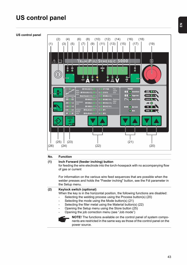
EN
US control panel
US control panel
No. Function
(1) Inch Forward (feeder inching) buttonfor feeding the wire electrode into the torch-hosepack with no accompanying flow of gas or current
For information on the various wire feed sequences that are possible when the welder presses and holds the "Feeder inching" button, see the Fdi parameter in the Setup menu.
(2) Keylock switch (optional)When the key is in the horizontal position, the following functions are disabled:- Selecting the welding process using the Process button(s) (20)- Selecting the mode using the Mode button(s) (21)- Selecting the filler metal using the Material button(s) (22)- Opening the Setup menu using the Store button (25)- Opening the job correction menu (see “Job mode”)
NOTE! The functions available on the control panel of system compo-nents are restricted in the same way as those of the control panel on the power source.
(14)(4)(1)
(26)(25)
(5)(18)
(15)(12)
(11)(10)
(3)(6)
(9)(7)(16)(8)
(24)(23)
(22)
(13)(2)
(19)(17)
(20)(21)
43
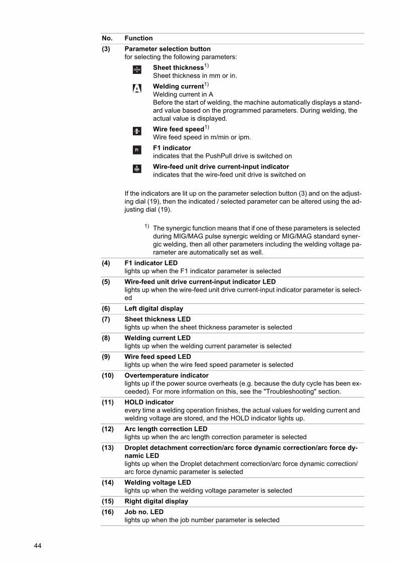
(3) Parameter selection buttonfor selecting the following parameters:
Sheet thickness1)
Sheet thickness in mm or in.
Welding current1)
Welding current in ABefore the start of welding, the machine automatically displays a stand-ard value based on the programmed parameters. During welding, the actual value is displayed.
Wire feed speed1)
Wire feed speed in m/min or ipm.
F1 indicatorindicates that the PushPull drive is switched on
Wire-feed unit drive current-input indicatorindicates that the wire-feed unit drive is switched on
If the indicators are lit up on the parameter selection button (3) and on the adjust-ing dial (19), then the indicated / selected parameter can be altered using the ad-justing dial (19).
1) The synergic function means that if one of these parameters is selected during MIG/MAG pulse synergic welding or MIG/MAG standard syner-gic welding, then all other parameters including the welding voltage pa-rameter are automatically set as well.
(4) F1 indicator LEDlights up when the F1 indicator parameter is selected
(5) Wire-feed unit drive current-input indicator LEDlights up when the wire-feed unit drive current-input indicator parameter is select-ed
(6) Left digital display
(7) Sheet thickness LEDlights up when the sheet thickness parameter is selected
(8) Welding current LEDlights up when the welding current parameter is selected
(9) Wire feed speed LEDlights up when the wire feed speed parameter is selected
(10) Overtemperature indicatorlights up if the power source overheats (e.g. because the duty cycle has been ex-ceeded). For more information on this, see the "Troubleshooting" section.
(11) HOLD indicatorevery time a welding operation finishes, the actual values for welding current and welding voltage are stored, and the HOLD indicator lights up.
(12) Arc length correction LEDlights up when the arc length correction parameter is selected
(13) Droplet detachment correction/arc force dynamic correction/arc force dy-namic LEDlights up when the Droplet detachment correction/arc force dynamic correction/arc force dynamic parameter is selected
(14) Welding voltage LEDlights up when the welding voltage parameter is selected
(15) Right digital display
(16) Job no. LEDlights up when the job number parameter is selected
No. Function
44
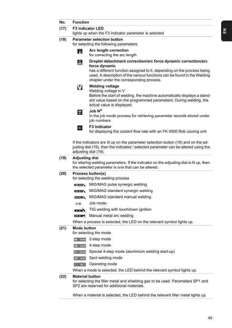
EN
(17) F3 indicator LEDlights up when the F3 indicator parameter is selected
(18) Parameter selection buttonfor selecting the following parameters:
Arc length correctionfor correcting the arc length
Droplet detachment correction/arc force dynamic correction/arc force dynamichas a different function assigned to it, depending on the process being used. A description of the various functions can be found in the Welding chapter under the corresponding process.
Welding voltageWelding voltage in VBefore the start of welding, the machine automatically displays a stand-ard value based on the programmed parameters. During welding, the actual value is displayed.
Job No
In the job mode process for retrieving parameter records stored under job numbers
F3 indicatorfor displaying the coolant flow rate with an FK 4000 Rob cooling unit
If the indicators are lit up on the parameter selection button (18) and on the ad-justing dial (19), then the indicated / selected parameter can be altered using the adjusting dial (19).
(19) Adjusting dialfor altering welding parameters. If the indicator on the adjusting dial is lit up, then the selected parameter is one that can be altered.
(20) Process button(s)for selecting the welding process
MIG/MAG pulse synergic welding
MIG/MAG standard synergic welding
MIG/MAG standard manual welding
Job mode
TIG welding with touchdown ignition
Manual metal arc welding
When a process is selected, the LED on the relevant symbol lights up.
(21) Mode buttonfor selecting the mode
2-step mode
4-step mode
Special 4-step mode (aluminium welding start-up)
Spot welding mode
Operating mode
When a mode is selected, the LED behind the relevant symbol lights up.
(22) Material buttonfor selecting the filler metal and shielding gas to be used. Parameters SP1 and SP2 are reserved for additional materials.
When a material is selected, the LED behind the relevant filler metal lights up.
No. Function
45
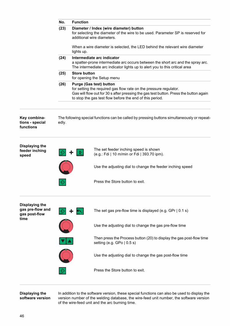
Key combina-tions - special functions
The following special functions can be called by pressing buttons simultaneously or repeat-edly.
Displaying the feeder inching speed
Displaying the gas pre-flow and gas post-flow time
Displaying the software version
In addition to the software version, these special functions can also be used to display the version number of the welding database, the wire-feed unit number, the software version of the wire-feed unit and the arc burning time.
(23) Diameter / Index (wire diameter) buttonfor selecting the diameter of the wire to be used. Parameter SP is reserved for additional wire diameters.
When a wire diameter is selected, the LED behind the relevant wire diameter lights up.
(24) Intermediate arc indicatora spatter-prone intermediate arc occurs between the short arc and the spray arc. The intermediate arc indicator lights up to alert you to this critical area
(25) Store buttonfor opening the Setup menu
(26) Purge (Gas test) buttonfor setting the required gas flow rate on the pressure regulator.Gas will flow out for 30 s after pressing the gas test button. Press the button again to stop the gas test flow before the end of this period.
No. Function
The set feeder inching speed is shown(e.g.: Fdi | 10 m/min or Fdi | 393.70 ipm).
Use the adjusting dial to change the feeder inching speed
Press the Store button to exit.
The set gas pre-flow time is displayed (e.g. GPr | 0.1 s)
Use the adjusting dial to change the gas pre-flow time
Then press the Process button (20) to display the gas post-flow time setting (e.g. GPo | 0.5 s)
Use the adjusting dial to change the gas post-flow time
Press the Store button to exit.
46

EN
The software version is displayed
Press the Material button (22) to display the version number of the welding database(e.g.: 0 | 029 = M0029).
Press the Material button (22) again to display the number of the wire-feed unit (A or B in the case of twin-head mounts) and the soft-ware version of the wire-feed unit(e.g.: A 1.5 | 0.23).
Press the Material button (22) a third time to display the actual arc burning time since starting for the first time (e.g. "654 | 32.1" = 65,432.1 h = 65,432 h, 6 min)
NOTE! The arc burning time indicator is not suitable as a basis for calculating hiring fees, guarantee, etc.
Press the Store button to exit.
47
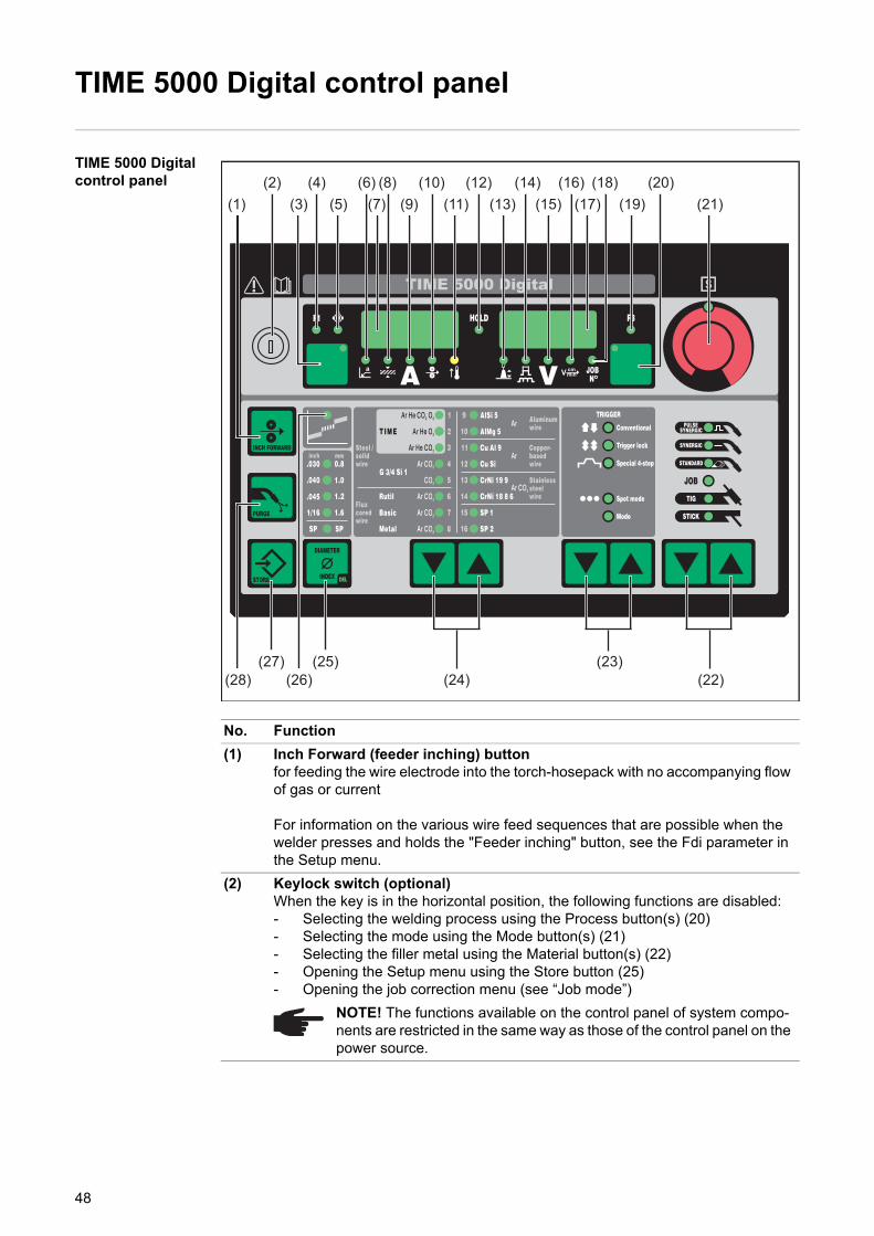
TIME 5000 Digital control panel
TIME 5000 Digital control panel
No. Function
(1) Inch Forward (feeder inching) buttonfor feeding the wire electrode into the torch-hosepack with no accompanying flow of gas or current
For information on the various wire feed sequences that are possible when the welder presses and holds the "Feeder inching" button, see the Fdi parameter in the Setup menu.
(2) Keylock switch (optional)When the key is in the horizontal position, the following functions are disabled:- Selecting the welding process using the Process button(s) (20)- Selecting the mode using the Mode button(s) (21)- Selecting the filler metal using the Material button(s) (22)- Opening the Setup menu using the Store button (25)- Opening the job correction menu (see “Job mode”)
NOTE! The functions available on the control panel of system compo-nents are restricted in the same way as those of the control panel on the power source.
(14)(4)(1)
(28) (26)(25)
(5)(18)
(15)(12)
(11)(10)
(3)(6)
(9)(7)(16)(8)
(27)(24)
(23)(22)
(13)(2)
(19)(17)(20)
(21)
48
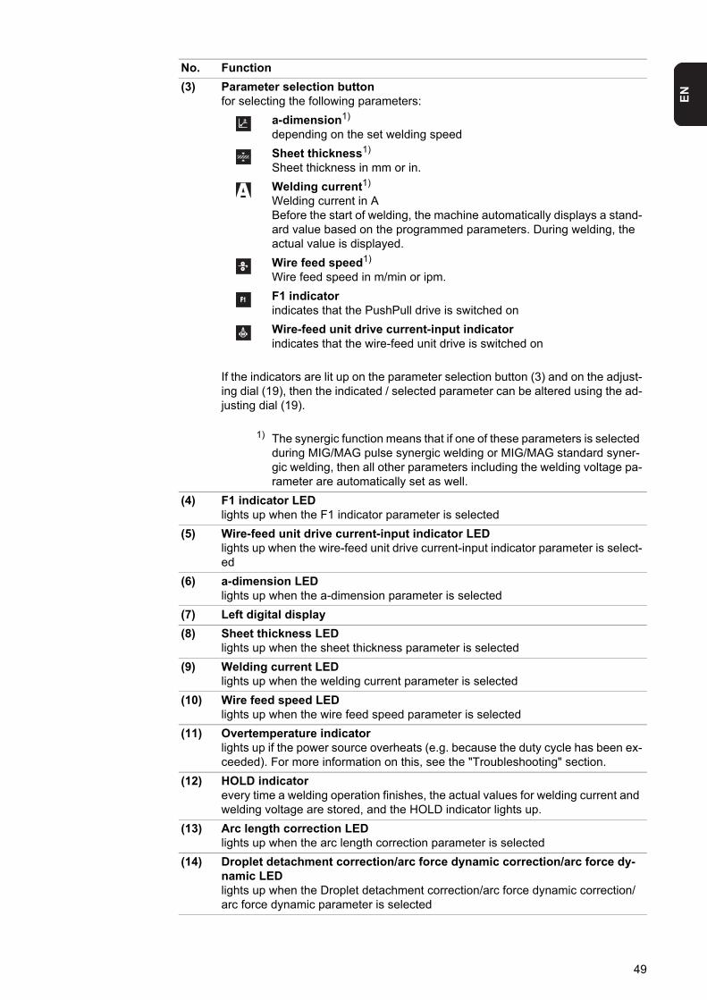
EN
(3) Parameter selection buttonfor selecting the following parameters:
a-dimension1)
depending on the set welding speed
Sheet thickness1)
Sheet thickness in mm or in.
Welding current1)
Welding current in ABefore the start of welding, the machine automatically displays a stand-ard value based on the programmed parameters. During welding, the actual value is displayed.
Wire feed speed1)
Wire feed speed in m/min or ipm.
F1 indicatorindicates that the PushPull drive is switched on
Wire-feed unit drive current-input indicatorindicates that the wire-feed unit drive is switched on
If the indicators are lit up on the parameter selection button (3) and on the adjust-ing dial (19), then the indicated / selected parameter can be altered using the ad-justing dial (19).
1) The synergic function means that if one of these parameters is selected during MIG/MAG pulse synergic welding or MIG/MAG standard syner-gic welding, then all other parameters including the welding voltage pa-rameter are automatically set as well.
(4) F1 indicator LEDlights up when the F1 indicator parameter is selected
(5) Wire-feed unit drive current-input indicator LEDlights up when the wire-feed unit drive current-input indicator parameter is select-ed
(6) a-dimension LEDlights up when the a-dimension parameter is selected
(7) Left digital display
(8) Sheet thickness LEDlights up when the sheet thickness parameter is selected
(9) Welding current LEDlights up when the welding current parameter is selected
(10) Wire feed speed LEDlights up when the wire feed speed parameter is selected
(11) Overtemperature indicatorlights up if the power source overheats (e.g. because the duty cycle has been ex-ceeded). For more information on this, see the "Troubleshooting" section.
(12) HOLD indicatorevery time a welding operation finishes, the actual values for welding current and welding voltage are stored, and the HOLD indicator lights up.
(13) Arc length correction LEDlights up when the arc length correction parameter is selected
(14) Droplet detachment correction/arc force dynamic correction/arc force dy-namic LEDlights up when the Droplet detachment correction/arc force dynamic correction/arc force dynamic parameter is selected
No. Function
49
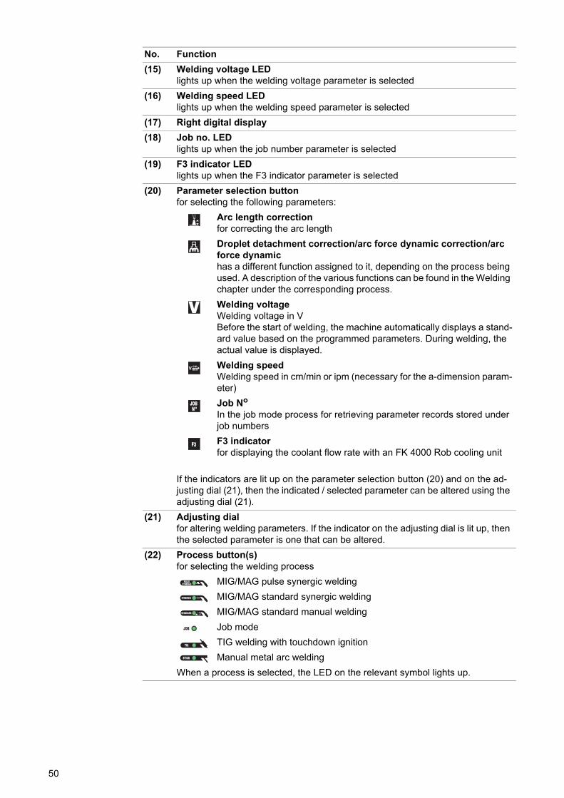
(15) Welding voltage LEDlights up when the welding voltage parameter is selected
(16) Welding speed LEDlights up when the welding speed parameter is selected
(17) Right digital display
(18) Job no. LEDlights up when the job number parameter is selected
(19) F3 indicator LEDlights up when the F3 indicator parameter is selected
(20) Parameter selection buttonfor selecting the following parameters:
Arc length correctionfor correcting the arc length
Droplet detachment correction/arc force dynamic correction/arc force dynamichas a different function assigned to it, depending on the process being used. A description of the various functions can be found in the Welding chapter under the corresponding process.
Welding voltageWelding voltage in VBefore the start of welding, the machine automatically displays a stand-ard value based on the programmed parameters. During welding, the actual value is displayed.
Welding speedWelding speed in cm/min or ipm (necessary for the a-dimension param-eter)
Job No
In the job mode process for retrieving parameter records stored under job numbers
F3 indicatorfor displaying the coolant flow rate with an FK 4000 Rob cooling unit
If the indicators are lit up on the parameter selection button (20) and on the ad-justing dial (21), then the indicated / selected parameter can be altered using the adjusting dial (21).
(21) Adjusting dialfor altering welding parameters. If the indicator on the adjusting dial is lit up, then the selected parameter is one that can be altered.
(22) Process button(s)for selecting the welding process
MIG/MAG pulse synergic welding
MIG/MAG standard synergic welding
MIG/MAG standard manual welding
Job mode
TIG welding with touchdown ignition
Manual metal arc welding
When a process is selected, the LED on the relevant symbol lights up.
No. Function
50
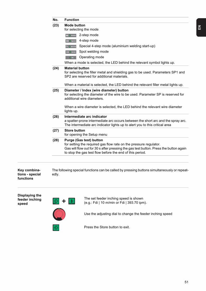
EN
Key combina-tions - special functions
The following special functions can be called by pressing buttons simultaneously or repeat-edly.
Displaying the feeder inching speed
(23) Mode buttonfor selecting the mode
2-step mode
4-step mode
Special 4-step mode (aluminium welding start-up)
Spot welding mode
Operating mode
When a mode is selected, the LED behind the relevant symbol lights up.
(24) Material buttonfor selecting the filler metal and shielding gas to be used. Parameters SP1 and SP2 are reserved for additional materials.
When a material is selected, the LED behind the relevant filler metal lights up.
(25) Diameter / Index (wire diameter) buttonfor selecting the diameter of the wire to be used. Parameter SP is reserved for additional wire diameters.
When a wire diameter is selected, the LED behind the relevant wire diameter lights up.
(26) Intermediate arc indicatora spatter-prone intermediate arc occurs between the short arc and the spray arc. The intermediate arc indicator lights up to alert you to this critical area
(27) Store buttonfor opening the Setup menu
(28) Purge (Gas test) buttonfor setting the required gas flow rate on the pressure regulator.Gas will flow out for 30 s after pressing the gas test button. Press the button again to stop the gas test flow before the end of this period.
No. Function
The set feeder inching speed is shown(e.g.: Fdi | 10 m/min or Fdi | 393.70 ipm).
Use the adjusting dial to change the feeder inching speed
Press the Store button to exit.
51
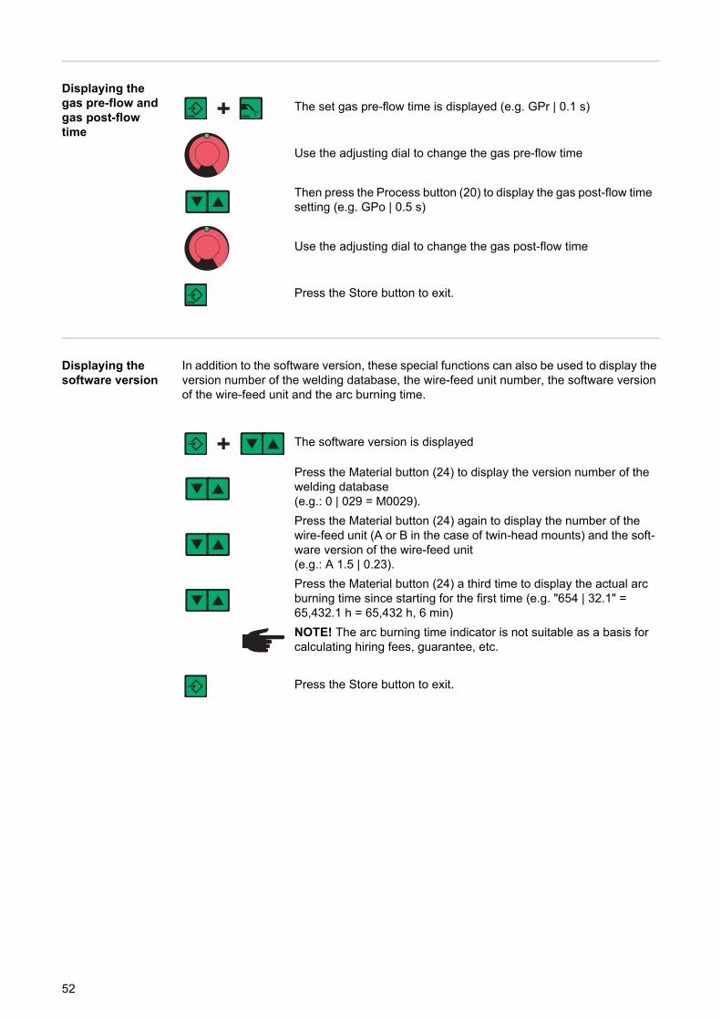
Displaying the gas pre-flow and gas post-flow time
Displaying the software version
In addition to the software version, these special functions can also be used to display the version number of the welding database, the wire-feed unit number, the software version of the wire-feed unit and the arc burning time.
The set gas pre-flow time is displayed (e.g. GPr | 0.1 s)
Use the adjusting dial to change the gas pre-flow time
Then press the Process button (20) to display the gas post-flow time setting (e.g. GPo | 0.5 s)
Use the adjusting dial to change the gas post-flow time
Press the Store button to exit.
The software version is displayed
Press the Material button (24) to display the version number of the welding database(e.g.: 0 | 029 = M0029).
Press the Material button (24) again to display the number of the wire-feed unit (A or B in the case of twin-head mounts) and the soft-ware version of the wire-feed unit(e.g.: A 1.5 | 0.23).
Press the Material button (24) a third time to display the actual arc burning time since starting for the first time (e.g. "654 | 32.1" = 65,432.1 h = 65,432 h, 6 min)
NOTE! The arc burning time indicator is not suitable as a basis for calculating hiring fees, guarantee, etc.
Press the Store button to exit.
52
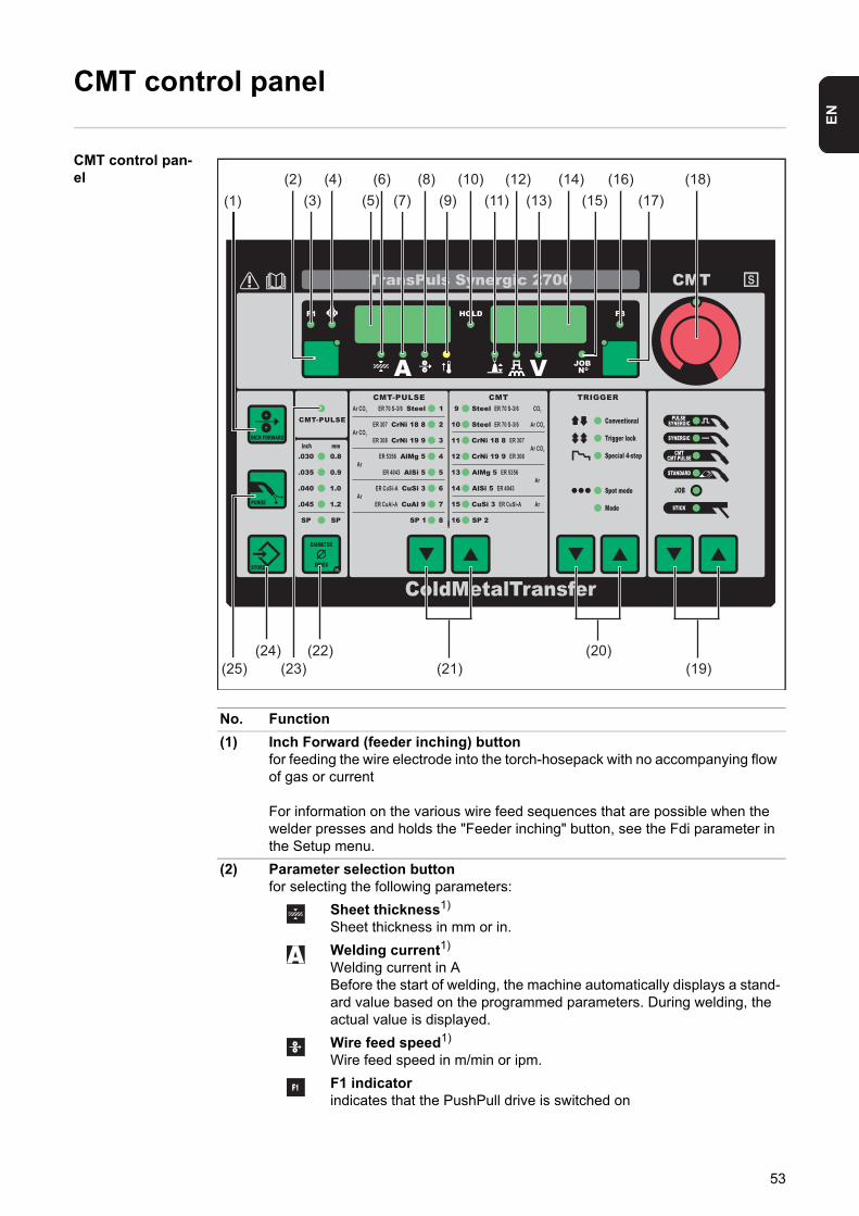
EN
CMT control panel
CMT control pan-el
No. Function
(1) Inch Forward (feeder inching) buttonfor feeding the wire electrode into the torch-hosepack with no accompanying flow of gas or current
For information on the various wire feed sequences that are possible when the welder presses and holds the "Feeder inching" button, see the Fdi parameter in the Setup menu.
(2) Parameter selection buttonfor selecting the following parameters:
Sheet thickness1)
Sheet thickness in mm or in.
Welding current1)
Welding current in ABefore the start of welding, the machine automatically displays a stand-ard value based on the programmed parameters. During welding, the actual value is displayed.
Wire feed speed1)
Wire feed speed in m/min or ipm.
F1 indicatorindicates that the PushPull drive is switched on
(14)(4)(1)
(25)
(5)(18)
(15)(12)
(11)(10)
(3)(6)
(9)(7)(16)(8)
(24)(23)
(22)
(13)(2)
(19)
(17)
(20)(21)
53
Wire-feed unit drive current-input indicatorindicates that the wire-feed unit drive is switched on
If the indicators are lit up on the parameter selection button (3) and on the adjust-ing dial (19), then the indicated / selected parameter can be altered using the ad-justing dial (19).
1) The synergic function means that if one of these parameters is selected during MIG/MAG pulse synergic welding or MIG/MAG standard syner-gic welding, then all other parameters including the welding voltage pa-rameter are automatically set as well.
(3) F1 indicator LEDlights up when the F1 indicator parameter is selected
(4) Wire-feed unit drive current-input indicator LEDlights up when the wire-feed unit drive current-input indicator parameter is select-ed
(5) Left digital display
(6) Sheet thickness LEDlights up when the sheet thickness parameter is selected
(7) Welding current LEDlights up when the welding current parameter is selected
(8) Wire feed speed LEDlights up when the wire feed speed parameter is selected
(9) Overtemperature indicatorlights up if the power source overheats (e.g. because the duty cycle has been ex-ceeded). For more information on this, see the "Troubleshooting" section.
(10) HOLD indicatorevery time a welding operation finishes, the actual values for welding current and welding voltage are stored, and the HOLD indicator lights up.
(11) Arc length correction LEDlights up when the arc length correction parameter is selected
(12) Droplet detachment correction/arc force dynamic correction/arc force dy-namic LEDlights up when the Droplet detachment correction/arc force dynamic correction/arc force dynamic parameter is selected
(13) Welding voltage LEDlights up when the welding voltage parameter is selected
(14) Right digital display
(15) Job no. LEDlights up when the job number parameter is selected
(16) F3 indicator LEDlights up when the F3 indicator parameter is selected
No. Function
54
EN
(17) Parameter selection buttonfor selecting the following parameters:
Arc length correctionfor correcting the arc length
Droplet detachment correction/arc force dynamic correction/arc force dynamichas a different function assigned to it, depending on the process being used. A description of the various functions can be found in the Welding chapter under the corresponding process.
Welding voltageWelding voltage in VBefore the start of welding, the machine automatically displays a stand-ard value based on the programmed parameters. During welding, the actual value is displayed.
Job No
In the job mode process for retrieving parameter records stored under job numbers
F3 indicatorfor displaying the coolant flow rate with an FK 4000 Rob cooling unit
If the indicators are lit up on the parameter selection button (17) and on the ad-justing dial (18), then the indicated / selected parameter can be altered using the adjusting dial (18).
(18) Adjusting dialfor altering welding parameters. If the indicator on the adjusting dial is lit up, then the selected parameter is one that can be altered.
(19) Process button(s)for selecting the welding process
MIG/MAG pulse synergic welding
MIG/MAG standard synergic welding
CMT, CMT pulse
MIG/MAG standard manual welding
Job mode
Manual metal arc welding
When a process is selected, the LED on the relevant symbol lights up.
(20) Mode buttonfor selecting the mode
2-step mode
4-step mode
Special 4-step mode (aluminium welding start-up)
Spot welding mode
Operating mode
When a mode is selected, the LED behind the relevant symbol lights up.
(21) Material buttonfor selecting the filler metal and shielding gas to be used. Parameters SP1 and SP2 are reserved for additional materials.
When a material is selected, the LED behind the relevant filler metal lights up.
No. Function
55
Key combina-tions - special functions
The following special functions can be called by pressing buttons simultaneously or repeat-edly.
Displaying the feeder inching speed
Displaying the gas pre-flow and gas post-flow time
Displaying the software version
In addition to the software version, these special functions can also be used to display the version number of the welding database, the wire-feed unit number, the software version of the wire-feed unit and the arc burning time.
(22) Diameter / Index (wire diameter) buttonfor selecting the diameter of the wire to be used. Parameter SP is reserved for additional wire diameters.
When a wire diameter is selected, the LED behind the relevant wire diameter lights up.
(23) CMT Pulse indicatorlights up when a CMT/pulse characteristic is selected
(24) Store buttonfor opening the Setup menu
(25) Purge (Gas test) buttonfor setting the required gas flow rate on the pressure regulator.Gas will flow out for 30 s after pressing the gas test button. Press the button again to stop the gas test flow before the end of this period.
No. Function
The set feeder inching speed is shown(e.g.: Fdi | 10 m/min or Fdi | 393.70 ipm).
Use the adjusting dial to change the feeder inching speed
Press the Store button to exit.
The set gas pre-flow time is displayed (e.g. GPr | 0.1 s)
Use the adjusting dial to change the gas pre-flow time
Then press the Process button (20) to display the gas post-flow time setting (e.g. GPo | 0.5 s)
Use the adjusting dial to change the gas post-flow time
Press the Store button to exit.
56

EN
The software version is displayed
Press the Material button (24) to display the version number of the welding database(e.g.: 0 | 029 = M0029).
Press the Material button (24) again to display the number of the wire-feed unit (A or B in the case of twin-head mounts) and the soft-ware version of the wire-feed unit(e.g.: A 1.5 | 0.23).
Press the Material button (24) a third time to display the actual arc burning time since starting for the first time (e.g. "654 | 32.1" = 65,432.1 h = 65,432 h, 6 min)
NOTE! The arc burning time indicator is not suitable as a basis for calculating hiring fees, guarantee, etc.
Press the Store button to exit.
57
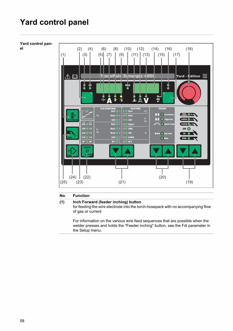
Yard control panel
Yard control pan-el
No. Function
(1) Inch Forward (feeder inching) buttonfor feeding the wire electrode into the torch-hosepack with no accompanying flow of gas or current
For information on the various wire feed sequences that are possible when the welder presses and holds the "Feeder inching" button, see the Fdi parameter in the Setup menu.
(14)(4)(1)
(25)
(5)(18)
(15)(12)
(11)(10)
(3)(6)
(9)(7)(16)(8)
(24)(23)
(22)
(13)(2)
(19)
(17)
(20)(21)
58
EN
(2) Parameter selection buttonfor selecting the following parameters:
Sheet thickness1)
Sheet thickness in mm or in.
Welding current1)
Welding current in ABefore the start of welding, the machine automatically displays a stand-ard value based on the programmed parameters. During welding, the actual value is displayed.
Wire feed speed1)
Wire feed speed in m/min or ipm.
F1 indicatorindicates that the PushPull drive is switched on
Wire-feed unit drive current-input indicatorindicates that the wire-feed unit drive is switched on
If the indicators are lit up on the parameter selection button (2) and on the adjust-ing dial (18), then the indicated / selected parameter can be altered using the ad-justing dial (18).
1) The synergic function means that if one of these parameters is selected during MIG/MAG pulse synergic welding or MIG/MAG standard syner-gic welding, then all other parameters including the welding voltage pa-rameter are automatically set as well.
(3) F1 indicator LEDlights up when the F1 indicator parameter is selected
(4) Wire-feed unit drive current-input indicator LEDlights up when the wire-feed unit drive current-input indicator parameter is select-ed
(5) Left digital display
(6) Sheet thickness LEDlights up when the sheet thickness parameter is selected
(7) Welding current LEDlights up when the welding current parameter is selected
(8) Wire feed speed LEDlights up when the wire feed speed parameter is selected
(9) Overtemperature indicatorlights up if the power source overheats (e.g. because the duty cycle has been ex-ceeded). For more information on this, see the "Troubleshooting" section.
(10) HOLD indicatorevery time a welding operation finishes, the actual values for welding current and welding voltage are stored, and the HOLD indicator lights up.
(11) Arc length correction LEDlights up when the arc length correction parameter is selected
(12) Droplet detachment correction/arc force dynamic correction/arc force dy-namic LEDlights up when the Droplet detachment correction/arc force dynamic correction/arc force dynamic parameter is selected
(13) Welding voltage LEDlights up when the welding voltage parameter is selected
(14) Right digital display
(15) Job no. LEDlights up when the job number parameter is selected
No. Function
59
(16) F3 indicator LEDlights up when the F3 indicator parameter is selected
(17) Parameter selection buttonfor selecting the following parameters:
Arc length correctionfor correcting the arc length
Droplet detachment correction/arc force dynamic correction/arc force dynamichas a different function assigned to it, depending on the process being used. A description of the various functions can be found in the Welding chapter under the corresponding process.
Welding voltageWelding voltage in VBefore the start of welding, the machine automatically displays a stand-ard value based on the programmed parameters. During welding, the actual value is displayed.
Job No
In the job mode process for retrieving parameter records stored under job numbers
F3 indicatorfor displaying the coolant flow rate with an FK 4000 Rob cooling unit
If the indicators are lit up on the parameter selection button (17) and on the ad-justing dial (18), then the indicated / selected parameter can be altered using the adjusting dial (18).
(18) Adjusting dialfor altering welding parameters. If the indicator on the adjusting dial is lit up, then the selected parameter is one that can be altered.
(19) Process button(s)for selecting the welding process
MIG/MAG pulse synergic welding
MIG/MAG standard synergic welding
MIG/MAG standard manual welding
Job mode
TIG welding with touchdown ignition
Manual metal arc welding
When a process is selected, the LED on the relevant symbol lights up.
(20) Mode buttonfor selecting the mode
2-step mode
4-step mode
Special 4-step mode (aluminium welding start-up)
Spot welding mode
Operating mode
When a mode is selected, the LED behind the relevant symbol lights up.
(21) Material buttonfor selecting the filler metal and shielding gas to be used. Parameters SP1 and SP2 are reserved for additional materials.
When a material is selected, the LED behind the relevant filler metal lights up.
No. Function
60
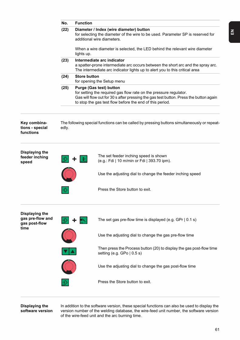
EN
Key combina-tions - special functions
The following special functions can be called by pressing buttons simultaneously or repeat-edly.
Displaying the feeder inching speed
Displaying the gas pre-flow and gas post-flow time
Displaying the software version
In addition to the software version, these special functions can also be used to display the version number of the welding database, the wire-feed unit number, the software version of the wire-feed unit and the arc burning time.
(22) Diameter / Index (wire diameter) buttonfor selecting the diameter of the wire to be used. Parameter SP is reserved for additional wire diameters.
When a wire diameter is selected, the LED behind the relevant wire diameter lights up.
(23) Intermediate arc indicatora spatter-prone intermediate arc occurs between the short arc and the spray arc. The intermediate arc indicator lights up to alert you to this critical area
(24) Store buttonfor opening the Setup menu
(25) Purge (Gas test) buttonfor setting the required gas flow rate on the pressure regulator.Gas will flow out for 30 s after pressing the gas test button. Press the button again to stop the gas test flow before the end of this period.
No. Function
The set feeder inching speed is shown(e.g.: Fdi | 10 m/min or Fdi | 393.70 ipm).
Use the adjusting dial to change the feeder inching speed
Press the Store button to exit.
The set gas pre-flow time is displayed (e.g. GPr | 0.1 s)
Use the adjusting dial to change the gas pre-flow time
Then press the Process button (20) to display the gas post-flow time setting (e.g. GPo | 0.5 s)
Use the adjusting dial to change the gas post-flow time
Press the Store button to exit.
61

The software version is displayed
Press the Material button (24) to display the version number of the welding database(e.g.: 0 | 029 = M0029).
Press the Material button (24) again to display the number of the wire-feed unit (A or B in the case of twin-head mounts) and the soft-ware version of the wire-feed unit(e.g.: A 1.5 | 0.23).
Press the Material button (24) a third time to display the actual arc burning time since starting for the first time (e.g. "654 | 32.1" = 65,432.1 h = 65,432 h, 6 min)
NOTE! The arc burning time indicator is not suitable as a basis for calculating hiring fees, guarantee, etc.
Press the Store button to exit.
62
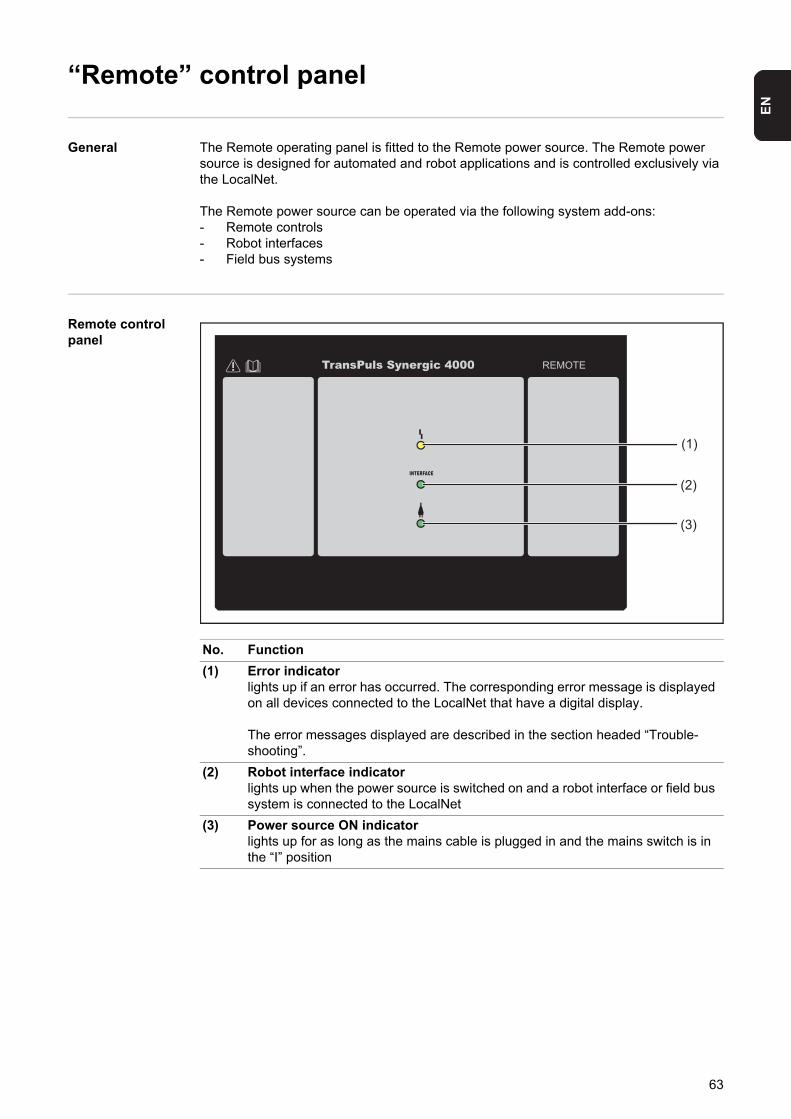
EN
“Remote” control panel
General The Remote operating panel is fitted to the Remote power source. The Remote power source is designed for automated and robot applications and is controlled exclusively via the LocalNet.
The Remote power source can be operated via the following system add-ons:- Remote controls- Robot interfaces- Field bus systems
Remote control panel
No. Function
(1) Error indicatorlights up if an error has occurred. The corresponding error message is displayed on all devices connected to the LocalNet that have a digital display.
The error messages displayed are described in the section headed “Trouble-shooting”.
(2) Robot interface indicatorlights up when the power source is switched on and a robot interface or field bus system is connected to the LocalNet
(3) Power source ON indicatorlights up for as long as the mains cable is plugged in and the mains switch is in the “I” position
TransPuls Synergic 4000
(3)
(2)
(1)
63
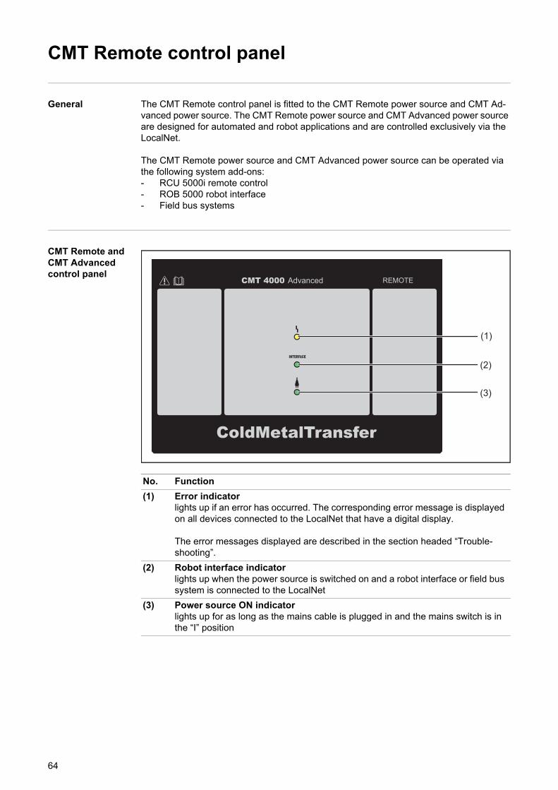
CMT Remote control panel
General The CMT Remote control panel is fitted to the CMT Remote power source and CMT Ad-vanced power source. The CMT Remote power source and CMT Advanced power source are designed for automated and robot applications and are controlled exclusively via the LocalNet.
The CMT Remote power source and CMT Advanced power source can be operated via the following system add-ons:- RCU 5000i remote control- ROB 5000 robot interface- Field bus systems
CMT Remote and CMT Advanced control panel
No. Function
(1) Error indicatorlights up if an error has occurred. The corresponding error message is displayed on all devices connected to the LocalNet that have a digital display.
The error messages displayed are described in the section headed “Trouble-shooting”.
(2) Robot interface indicatorlights up when the power source is switched on and a robot interface or field bus system is connected to the LocalNet
(3) Power source ON indicatorlights up for as long as the mains cable is plugged in and the mains switch is in the “I” position
CMT 4000 Advanced
(3)
(2)
(1)
64
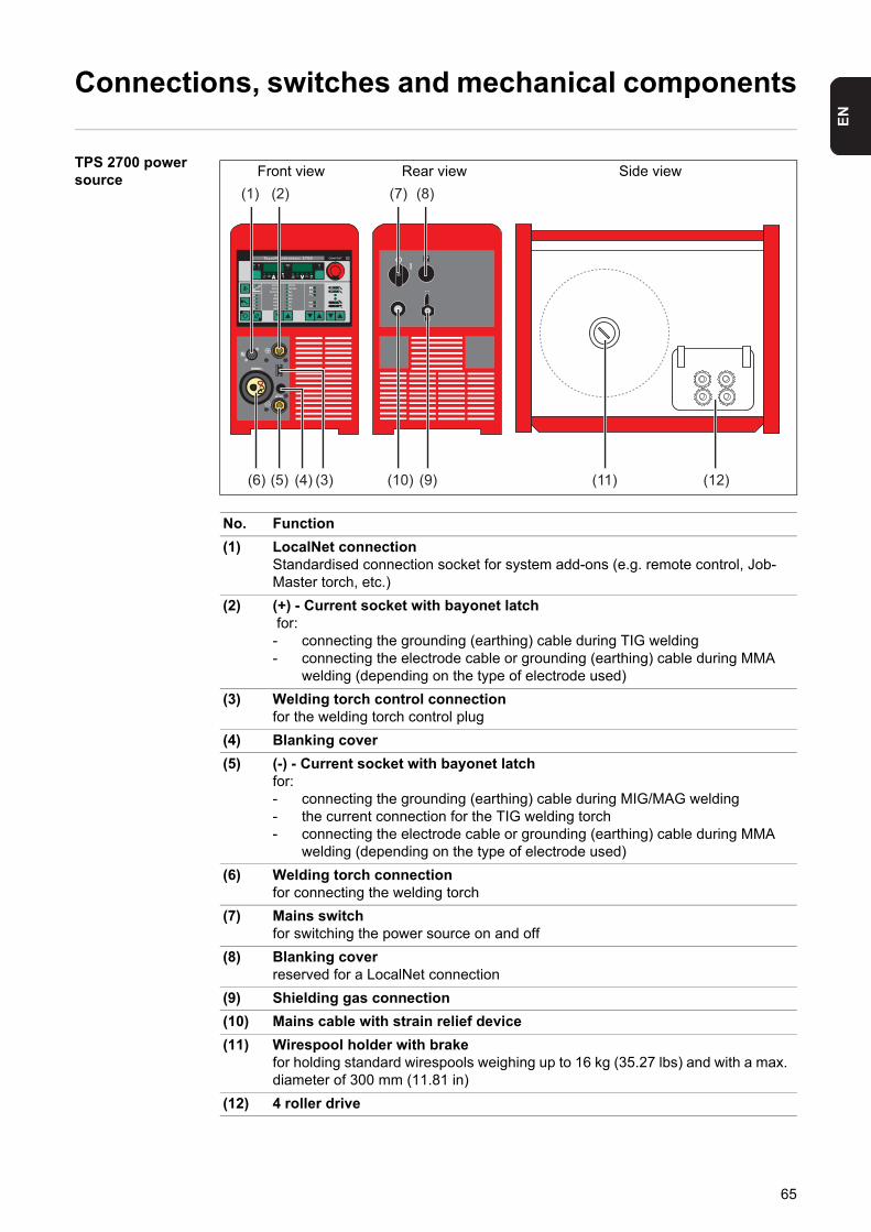
EN
Connections, switches and mechanical components
TPS 2700 power source
Front view Rear view Side view
No. Function
(1) LocalNet connectionStandardised connection socket for system add-ons (e.g. remote control, Job-Master torch, etc.)
(2) (+) - Current socket with bayonet latch for:- connecting the grounding (earthing) cable during TIG welding- connecting the electrode cable or grounding (earthing) cable during MMA
welding (depending on the type of electrode used)
(3) Welding torch control connectionfor the welding torch control plug
(4) Blanking cover
(5) (-) - Current socket with bayonet latchfor:- connecting the grounding (earthing) cable during MIG/MAG welding- the current connection for the TIG welding torch- connecting the electrode cable or grounding (earthing) cable during MMA
welding (depending on the type of electrode used)
(6) Welding torch connectionfor connecting the welding torch
(7) Mains switchfor switching the power source on and off
(8) Blanking coverreserved for a LocalNet connection
(9) Shielding gas connection
(10) Mains cable with strain relief device
(11) Wirespool holder with brakefor holding standard wirespools weighing up to 16 kg (35.27 lbs) and with a max. diameter of 300 mm (11.81 in)
(12) 4 roller drive
(1) (2)
(3)(4)(5)(6)
(7) (8)
)9()01( )21()11(
65
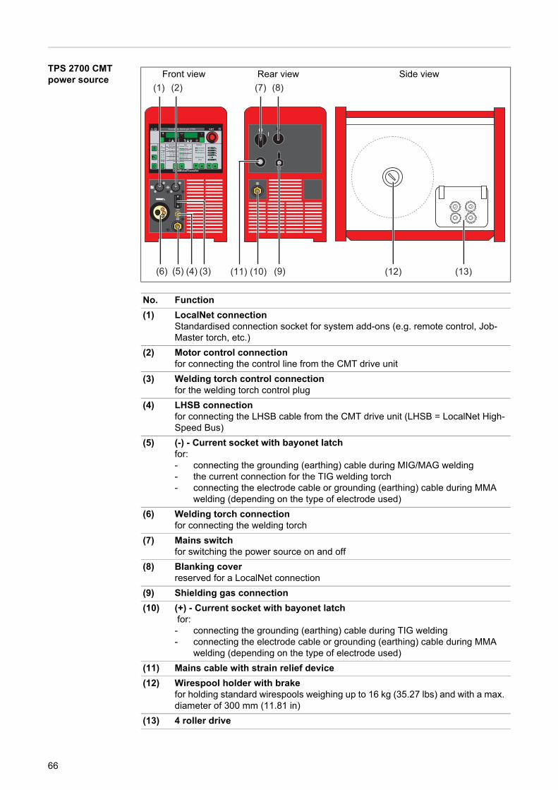
TPS 2700 CMT power source
Front view Rear view Side view
No. Function
(1) LocalNet connectionStandardised connection socket for system add-ons (e.g. remote control, Job-Master torch, etc.)
(2) Motor control connectionfor connecting the control line from the CMT drive unit
(3) Welding torch control connectionfor the welding torch control plug
(4) LHSB connectionfor connecting the LHSB cable from the CMT drive unit (LHSB = LocalNet High-Speed Bus)
(5) (-) - Current socket with bayonet latchfor:- connecting the grounding (earthing) cable during MIG/MAG welding- the current connection for the TIG welding torch- connecting the electrode cable or grounding (earthing) cable during MMA
welding (depending on the type of electrode used)
(6) Welding torch connectionfor connecting the welding torch
(7) Mains switchfor switching the power source on and off
(8) Blanking coverreserved for a LocalNet connection
(9) Shielding gas connection
(10) (+) - Current socket with bayonet latch for:- connecting the grounding (earthing) cable during TIG welding- connecting the electrode cable or grounding (earthing) cable during MMA
welding (depending on the type of electrode used)
(11) Mains cable with strain relief device
(12) Wirespool holder with brakefor holding standard wirespools weighing up to 16 kg (35.27 lbs) and with a max. diameter of 300 mm (11.81 in)
(13) 4 roller drive
(1) (2)
(3)(4)(5)(6)
(7) (8)
(9)(10)(11) (13)(12)
66
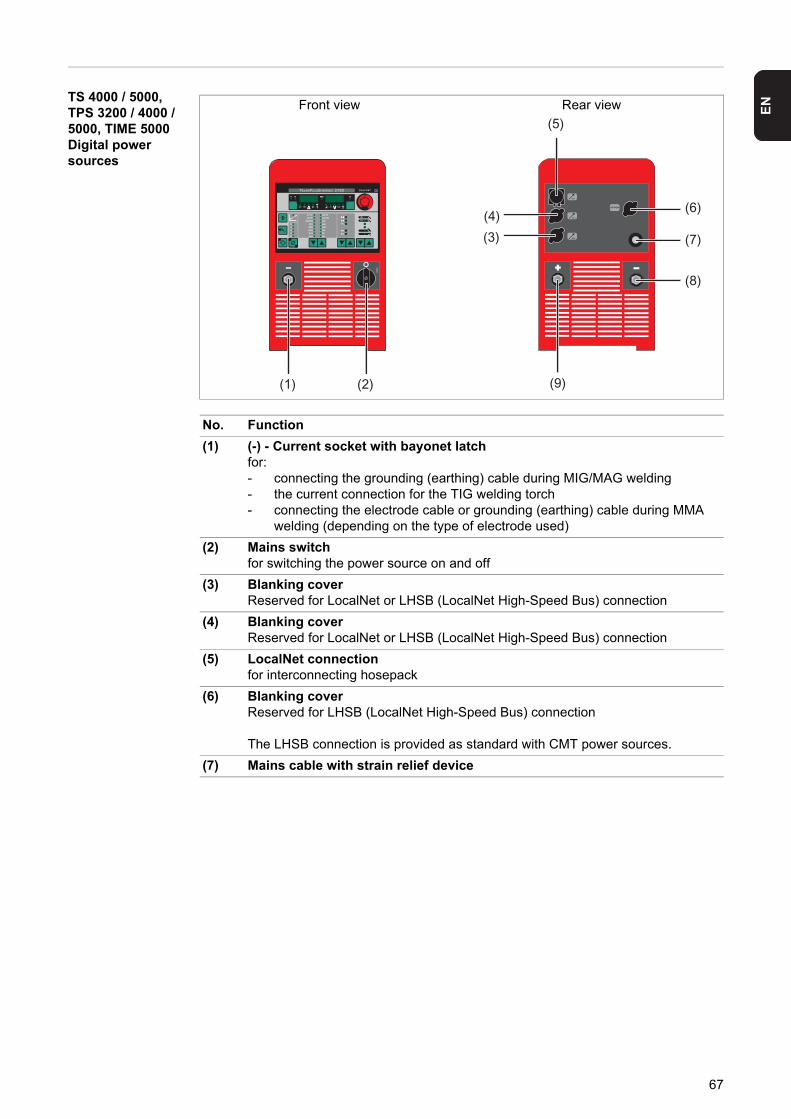
EN
TS 4000 / 5000,TPS 3200 / 4000 / 5000, TIME 5000 Digital power sources
Front view Rear view
No. Function
(1) (-) - Current socket with bayonet latchfor:- connecting the grounding (earthing) cable during MIG/MAG welding- the current connection for the TIG welding torch- connecting the electrode cable or grounding (earthing) cable during MMA
welding (depending on the type of electrode used)
(2) Mains switchfor switching the power source on and off
(3) Blanking coverReserved for LocalNet or LHSB (LocalNet High-Speed Bus) connection
(4) Blanking coverReserved for LocalNet or LHSB (LocalNet High-Speed Bus) connection
(5) LocalNet connectionfor interconnecting hosepack
(6) Blanking coverReserved for LHSB (LocalNet High-Speed Bus) connection
The LHSB connection is provided as standard with CMT power sources.
(7) Mains cable with strain relief device
(1) (2)
(3)
(4)
(5)
(6)
(7)
(8)
(9)
67
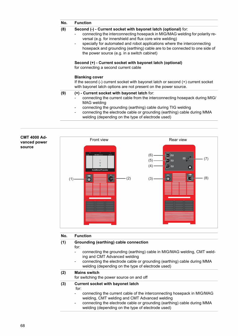
CMT 4000 Ad-vanced power source
(8) Second (-) - Current socket with bayonet latch (optional) for:- connecting the interconnecting hosepack in MIG/MAG welding for polarity re-
versal (e.g. for innershield and flux core wire welding)- specially for automated and robot applications where the interconnecting
hosepack and grounding (earthing) cable are to be connected to one side of the power source (e.g. in a switch cabinet)
Second (+) - Current socket with bayonet latch (optional)for connecting a second current cable
Blanking coverIf the second (-) current socket with bayonet latch or second (+) current socket with bayonet latch options are not present on the power source.
(9) (+) - Current socket with bayonet latch for:- connecting the current cable from the interconnecting hosepack during MIG/
MAG welding- connecting the grounding (earthing) cable during TIG welding- connecting the electrode cable or grounding (earthing) cable during MMA
welding (depending on the type of electrode used)
No. Function
Front view Rear view
No. Function
(1) Grounding (earthing) cable connectionfor:- connecting the grounding (earthing) cable in MIG/MAG welding, CMT weld-
ing and CMT Advanced welding- connecting the electrode cable or grounding (earthing) cable during MMA
welding (depending on the type of electrode used)
(2) Mains switchfor switching the power source on and off
(3) Current socket with bayonet latch for:- connecting the current cable of the interconnecting hosepack in MIG/MAG
welding, CMT welding and CMT Advanced welding- connecting the electrode cable or grounding (earthing) cable during MMA
welding (depending on the type of electrode used)
CMT 4000 Advanced
(1) (2)
LHSB
(3)
(4)(5) (7)
(8)
(6)
68

EN
(4) Blanking coverReserved for LocalNet connection
(5) Blanking coverReserved for LocalNet connection
(6) LocalNet connectionfor interconnecting hosepack
(7) LHSB (LocalNet High-Speed Bus) connection
(8) Mains cable with strain relief device
No. Function
69

70

Installation and commissioning

EN
Minimum equipment needed for welding task
General Depending on which welding process you intend to use, a certain minimum equipment lev-el will be needed in order to work with the power source.The welding processes and the minimum equipment levels required for the welding task are then described.
MIG/MAG gas-cooled welding
- Power source- Grounding (earthing) cable- MIG/MAG welding torch, gas-cooled- Gas connection (shielding gas supply)- Wire-feed unit (TS 4000 / 5000, TPS 3200 / 4000 / 5000 only)- Interconnecting hosepack (TS 4000/5000, TPS 3200/4000/5000 only)- Wire electrode
MIG/MAG water-cooled welding
- Power source- Cooling unit- Grounding (earthing) cable- MIG/MAG welding torch, water-cooled- Gas connection (shielding gas supply)- Wire-feed unit (TS 4000 / 5000, TPS 3200 / 4000 / 5000 only)- Interconnecting hosepack (TS 4000/5000, TPS 3200/4000/5000 only)- Wire electrode
MIG/MAG auto-mated welding
- Power source (TS 4000 / 5000, TPS 3200 / 4000 / 5000)- Robot interface or field bus connection- Grounding (earthing) cable- MIG/MAG robot welding torch or MIG/MAG machine welding torch (a cooling unit is
also required with water-cooled robot or machine welding torches)- Gas connection (shielding gas supply)- Wire-feed unit- Interconnecting hosepack- Wire electrode
CMT manual welding
- CMT power source- Grounding (earthing) cable- CMT welding torch with CMT drive unit and CMT wire buffer (a cooling unit is also re-
quired for water-cooled CMT applications)- CMT wire-feed unit (TPS 3200 / 4000 / 5000 only)- CMT interconnecting hosepack (TPS 3200 / 4000 / 5000 only)- Wire electrode- Gas connection (shielding gas supply)
73
CMT automated welding
- CMT power source: TPS 3200 / 4000 / 5000 (or CMT remote power source with RCU 5000i remote control)
- Robot interface or field bus connection- Grounding (earthing) cable- CMT welding torch incl. CMT drive unit- Cooling unit- CMT wire-feed unit- CMT interconnecting hosepack- CMT wire buffer- Wire electrode- Gas connection (shielding gas supply)
CMT Advanced welding
- CMT 4000 Advanced power source- RCU 5000i remote control- Robot interface or field bus connection- Grounding (earthing) cable- CMT welding torch incl. CMT drive unit- Cooling unit- CMT wire-feed unit- CMT interconnecting hosepack- CMT wire buffer- Wire electrode- Gas connection (shielding gas supply)
TIG DC welding - Power source- Grounding (earthing) cable- TIG gas valve welding torch- Gas connection (shielding gas supply)- Filler metal (depending on the application)
Manual metal arc welding
- Power source- Grounding (earthing) cable- Electrode holder- Rod electrodes
74
EN
Before installation and commissioning
Safety
Proper use The power source may only be used for MIG/MAG, MMA and TIG welding. Any use above and beyond this purpose is deemed improper. The manufacturer shall not be held liable for any damage arising from such usage.
Proper use also includes:- following all the information in the operating instructions- carrying out all the specified inspection and servicing work
Setup regulations The device is tested to IP 23 protection, meaning:- protection against penetration by solid foreign bodies with diameters > 12.5 mm (0.49
in.)- protection against direct sprays of water at any angle up to 60° from the vertical
The device can be set up and operated outdoors in accordance with IP23. Avoid direct wet-ting (e.g. from rain).
The venting duct is a very important safety feature. When choosing the installation location, ensure that the cooling air can enter and exit unhindered through the air ducts on the front and back of the device. Any electroconductive metallic dust (e.g. from grinding work) must not be allowed to get sucked into the device.
Mains connection The devices are designed to run at the mains voltage specified on the rating plate. If your version of the device does not come with mains cables and plugs ready-fitted, these must be fitted in accordance with national regulations and standards. For details of fuse protec-tion of the mains lead, please see the Technical Data.
WARNING! Operating the equipment incorrectly can cause serious injury and damage. Do not use the functions described until you have thoroughly read and understood the following documents:- these operating instructions- all the operating instructions for the system components, especially the safe-
ty rules
WARNING! If one of these devices topples over or falls it could cause serious or even fatal injury. Place devices, upright consoles and trolleys on a solid, level sur-face in such a way that they remain stable.
NOTE! Inadequately dimensioned electrical installations can cause serious dam-age. The mains lead and its fuse must be dimensioned to suit the local power sup-ply. The technical data shown on the rating plate applies.
Applies to TIME 5000 Digital power source:The standard mains plug allows the user to operate with a mains voltage of up to 400 V. For mains voltages up to 460 V, fit an approved mains plug or install the mains supply directly.
75
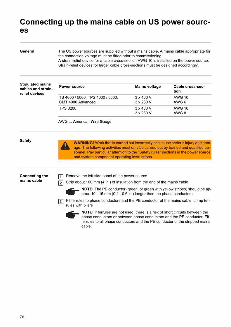
Connecting up the mains cable on US power sourc-es
General The US power sources are supplied without a mains cable. A mains cable appropriate for the connection voltage must be fitted prior to commissioning.A strain-relief device for a cable cross-section AWG 10 is installed on the power source. Strain-relief devices for larger cable cross-sections must be designed accordingly.
Stipulated mains cables and strain-relief devices
AWG ... American Wire Gauge
Safety
Connecting the mains cable
Remove the left side panel of the power source
Strip about 100 mm (4 in.) of insulation from the end of the mains cable
Fit ferrules to phase conductors and the PE conductor of the mains cable; crimp fer-rules with pliers
Power source Mains voltage Cable cross-sec-tion
TS 4000 / 5000, TPS 4000 / 5000, CMT 4000 Advanced
3 x 460 V3 x 230 V
AWG 10AWG 6
TPS 3200 3 x 460 V3 x 230 V
AWG 10AWG 8
WARNING! Work that is carried out incorrectly can cause serious injury and dam-age. The following activities must only be carried out by trained and qualified per-sonnel. Pay particular attention to the "Safety rules" sections in the power source and system component operating instructions.
NOTE! The PE conductor (green, or green with yellow stripes) should be ap-prox. 10 - 15 mm (0.4 - 0.6 in.) longer than the phase conductors.
NOTE! If ferrules are not used, there is a risk of short circuits between the phase conductors or between phase conductors and the PE conductor. Fit ferrules to all phase conductors and the PE conductor of the stripped mains cable.
12
3
76
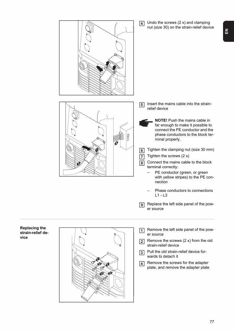
EN
Undo the screws (2 x) and clamping nut (size 30) on the strain-relief device
Insert the mains cable into the strain-relief device
Tighten the clamping nut (size 30 mm)
Tighten the screws (2 x)
Connect the mains cable to the block terminal correctly:
– PE conductor (green, or green with yellow stripes) to the PE con-nection
– Phase conductors to connections L1 - L3
Replace the left side panel of the pow-er source
Replacing the strain-relief de-vice
Remove the left side panel of the pow-er source
Remove the screws (2 x) from the old strain-relief device
Pull the old strain-relief device for-wards to detach it
Remove the screws for the adapter plate, and remove the adapter plate
4
PEW1V1U1
5
7
8
6
NOTE! Push the mains cable in far enough to make it possible to connect the PE conductor and the phase conductors to the block ter-minal properly.
5
678
9
2
3
24
4
1
2
3
4
77
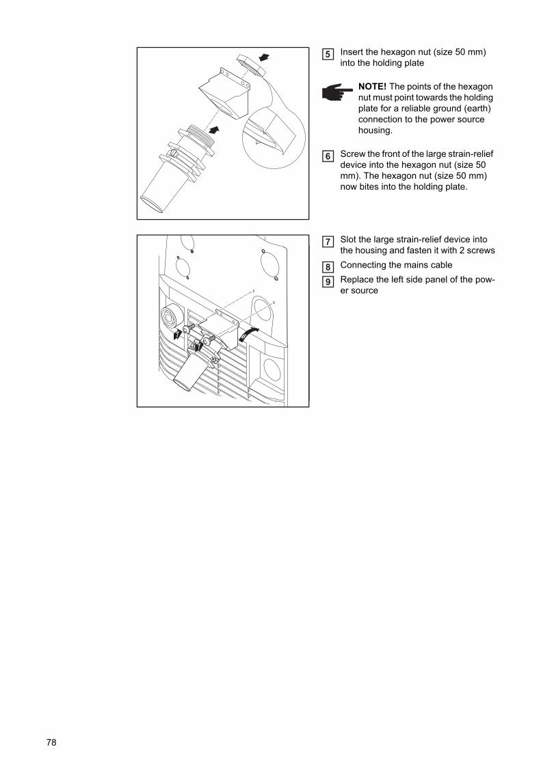
Insert the hexagon nut (size 50 mm) into the holding plate
Screw the front of the large strain-relief device into the hexagon nut (size 50 mm). The hexagon nut (size 50 mm) now bites into the holding plate.
Slot the large strain-relief device into the housing and fasten it with 2 screws
Connecting the mains cable
Replace the left side panel of the pow-er source
NOTE! The points of the hexagon nut must point towards the holding plate for a reliable ground (earth) connection to the power source housing.
5
6
67
7
7
89
78
EN
Start-up
Safety
Remarks on the cooling unit
We recommend using an FK 4000 R cooling unit for the following applications and situa-tions:- TS 4000 / 5000, TPS 3200 / 4000 / 5000 power sources- JobMaster welding torch- Push-pull welding torch- Robot welding- Hosepacks over 5 m long- MIG/MAG pulse synergic welding- In general, where welding is performed in higher power ranges
The cooling unit is powered from the power source. The cooling unit is ready for operation when the mains switch of the power source is in the - I - position.
More information on the cooling unit can be found in the operating instructions for the cool-ing unit.
Information on system compo-nents
The steps and activities described below include references to various system compo-nents, including:- Trolleys- Cooling units- Wire-feed unit holders- Wire-feed units- Interconnecting hosepacks- Welding torches- etc.
For more detailed information about installing and connecting the system components, please refer to the appropriate operating instructions.
Overview "Commissioning" is composed of the following sections:- Commissioning the TPS 2700- Commissioning the TS 4000/5000, TPS 3200/4000/5000- Commissioning the CMT 4000 Advanced
WARNING! An electric shock can be fatal. If the power source is connected to the mains electricity supply during installation, there is a high risk of very serious in-jury and damage. Before carrying out any work on the device make sure that:- the power source mains switch is in the "O" position- the power source is unplugged from the mains
79
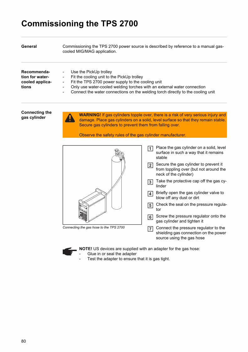
Commissioning the TPS 2700
General Commissioning the TPS 2700 power source is described by reference to a manual gas-cooled MIG/MAG application.
Recommenda-tion for water-cooled applica-tions
- Use the PickUp trolley- Fit the cooling unit to the PickUp trolley- Fit the TPS 2700 power supply to the cooling unit- Only use water-cooled welding torches with an external water connection- Connect the water connections on the welding torch directly to the cooling unit
Connecting the gas cylinder
Connecting the gas hose to the TPS 2700
Place the gas cylinder on a solid, level surface in such a way that it remains stable
Secure the gas cylinder to prevent it from toppling over (but not around the neck of the cylinder)
Take the protective cap off the gas cy-linder
Briefly open the gas cylinder valve to blow off any dust or dirt
Check the seal on the pressure regula-tor
Screw the pressure regulator onto the gas cylinder and tighten it
Connect the pressure regulator to the shielding gas connection on the power source using the gas hose
WARNING! If gas cylinders topple over, there is a risk of very serious injury and damage. Place gas cylinders on a solid, level surface so that they remain stable. Secure gas cylinders to prevent them from falling over.
Observe the safety rules of the gas cylinder manufacturer.
1
2
3
4
5
6
7
NOTE! US devices are supplied with an adapter for the gas hose:- Glue in or seal the adapter- Test the adapter to ensure that it is gas tight.
80
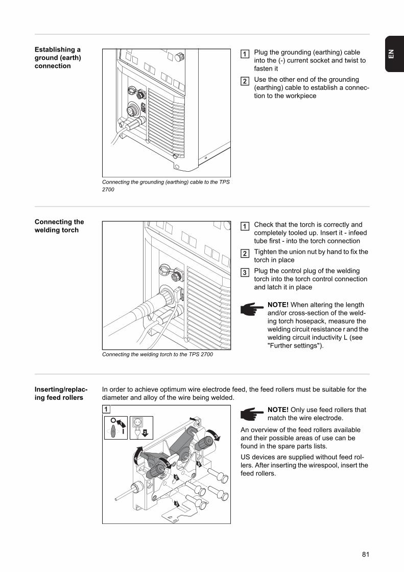
EN
Establishing aground (earth) connection
Connecting the grounding (earthing) cable to the TPS 2700
Plug the grounding (earthing) cable into the (-) current socket and twist to fasten it
Use the other end of the grounding (earthing) cable to establish a connec-tion to the workpiece
Connecting the welding torch
Connecting the welding torch to the TPS 2700
Check that the torch is correctly and completely tooled up. Insert it - infeed tube first - into the torch connection
Tighten the union nut by hand to fix the torch in place
Plug the control plug of the welding torch into the torch control connection and latch it in place
Inserting/replac-ing feed rollers
In order to achieve optimum wire electrode feed, the feed rollers must be suitable for the diameter and alloy of the wire being welded.
An overview of the feed rollers available and their possible areas of use can be found in the spare parts lists.
US devices are supplied without feed rol-lers. After inserting the wirespool, insert the feed rollers.
1
2
NOTE! When altering the length and/or cross-section of the weld-ing torch hosepack, measure the welding circuit resistance r and the welding circuit inductivity L (see "Further settings").
1
2
3
4
4
5
2
1
6
6
1 NOTE! Only use feed rollers that match the wire electrode.
81
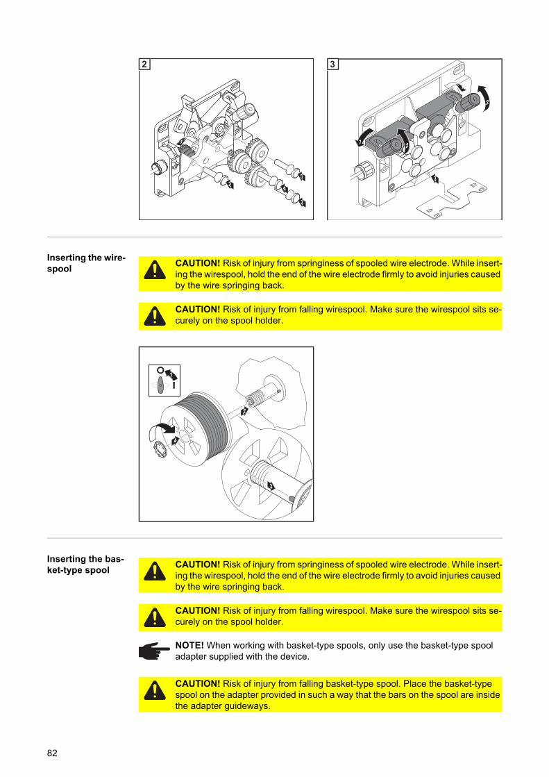
Inserting the wire-spool
Inserting the bas-ket-type spool
4
5
3
2
1
2
1
2
3
12
3
CAUTION! Risk of injury from springiness of spooled wire electrode. While insert-ing the wirespool, hold the end of the wire electrode firmly to avoid injuries caused by the wire springing back.
CAUTION! Risk of injury from falling wirespool. Make sure the wirespool sits se-curely on the spool holder.
1
2
4
3
CAUTION! Risk of injury from springiness of spooled wire electrode. While insert-ing the wirespool, hold the end of the wire electrode firmly to avoid injuries caused by the wire springing back.
CAUTION! Risk of injury from falling wirespool. Make sure the wirespool sits se-curely on the spool holder.
NOTE! When working with basket-type spools, only use the basket-type spool adapter supplied with the device.
CAUTION! Risk of injury from falling basket-type spool. Place the basket-type spool on the adapter provided in such a way that the bars on the spool are inside the adapter guideways.
82
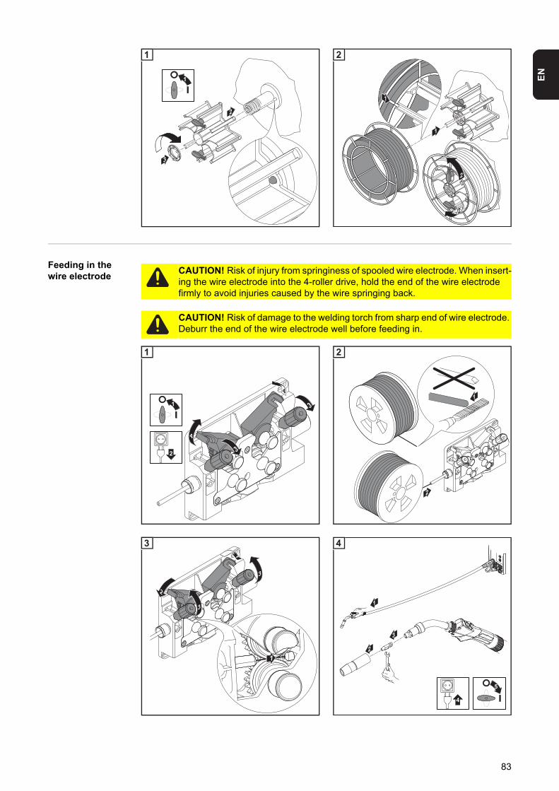
EN
Feeding in the wire electrode
3
2
1
1
1
2
2
1
2
CAUTION! Risk of injury from springiness of spooled wire electrode. When insert-ing the wire electrode into the 4-roller drive, hold the end of the wire electrode firmly to avoid injuries caused by the wire springing back.
CAUTION! Risk of damage to the welding torch from sharp end of wire electrode. Deburr the end of the wire electrode well before feeding in.
4
4
1
2
1
1
2
2
2
2
3
3
1
3
1
5
2
3
4
4
83
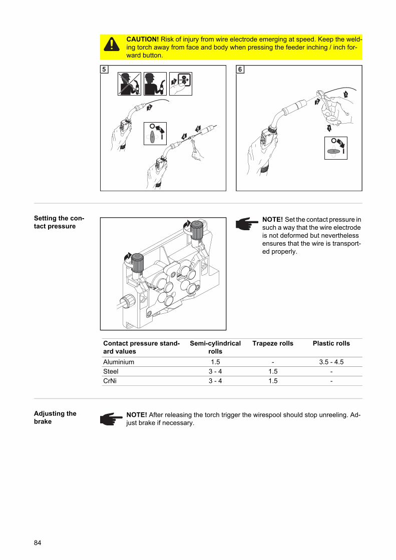
Setting the con-tact pressure
Adjusting the brake
CAUTION! Risk of injury from wire electrode emerging at speed. Keep the weld-ing torch away from face and body when pressing the feeder inching / inch for-ward button.
1
2
4
53
5
1
1
2
3
6
1
1
NOTE! Set the contact pressure in such a way that the wire electrode is not deformed but nevertheless ensures that the wire is transport-ed properly.
Contact pressure stand-ard values
Semi-cylindrical rolls
Trapeze rolls Plastic rolls
Aluminium 1.5 - 3.5 - 4.5
Steel 3 - 4 1.5 -
CrNi 3 - 4 1.5 -
NOTE! After releasing the torch trigger the wirespool should stop unreeling. Ad-just brake if necessary.
84
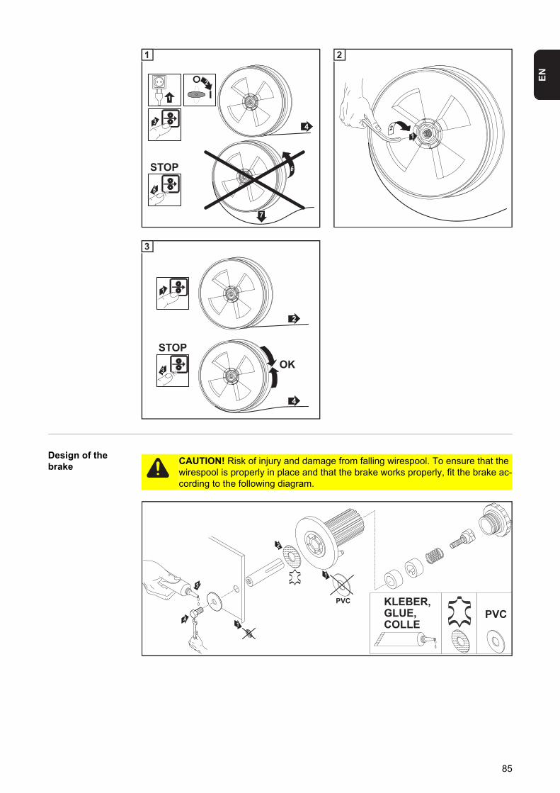
EN
Design of the brake
43
STOP 6
7
5
1
2
1
21
2
2
1
4
STOPOK
3
3
CAUTION! Risk of injury and damage from falling wirespool. To ensure that the wirespool is properly in place and that the brake works properly, fit the brake ac-cording to the following diagram.
1
2
PVC1
4
3
PVC KLEBER,GLUE,COLLE
85
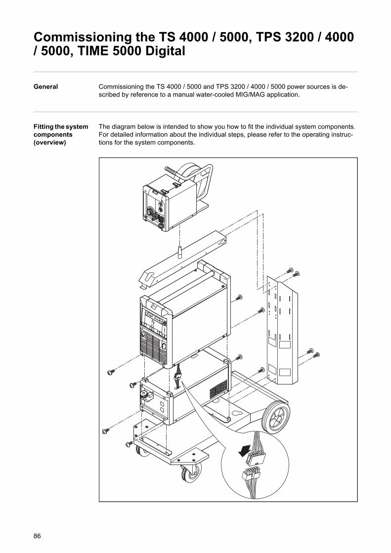
Commissioning the TS 4000 / 5000, TPS 3200 / 4000 / 5000, TIME 5000 Digital
General Commissioning the TS 4000 / 5000 and TPS 3200 / 4000 / 5000 power sources is de-scribed by reference to a manual water-cooled MIG/MAG application.
Fitting the system components (overview)
The diagram below is intended to show you how to fit the individual system components.For detailed information about the individual steps, please refer to the operating instruc-tions for the system components.
86
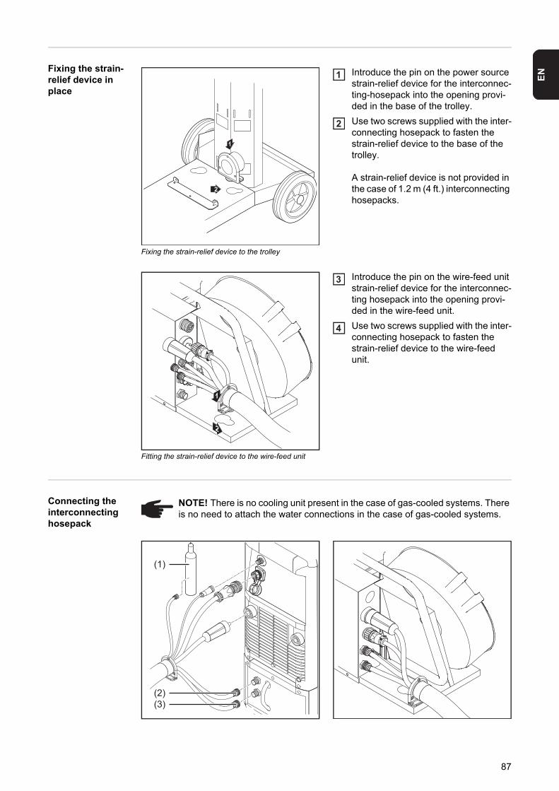
EN
Fixing the strain-relief device in place
Fixing the strain-relief device to the trolley
Introduce the pin on the power source strain-relief device for the interconnec-ting-hosepack into the opening provi-ded in the base of the trolley.
Use two screws supplied with the inter-connecting hosepack to fasten the strain-relief device to the base of the trolley.
A strain-relief device is not provided in the case of 1.2 m (4 ft.) interconnecting hosepacks.
Fitting the strain-relief device to the wire-feed unit
Introduce the pin on the wire-feed unit strain-relief device for the interconnec-ting hosepack into the opening provi-ded in the wire-feed unit.
Use two screws supplied with the inter-connecting hosepack to fasten the strain-relief device to the wire-feed unit.
Connecting the interconnecting hosepack
1
2
1
2
2
1
3
4
NOTE! There is no cooling unit present in the case of gas-cooled systems. There is no need to attach the water connections in the case of gas-cooled systems.
(1)
(2)(3)
87
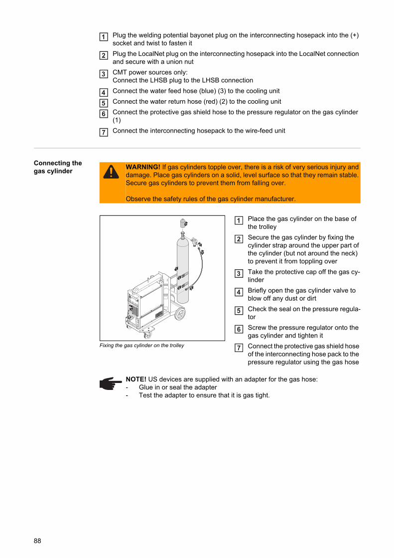
Plug the welding potential bayonet plug on the interconnecting hosepack into the (+) socket and twist to fasten it
Plug the LocalNet plug on the interconnecting hosepack into the LocalNet connection and secure with a union nut
CMT power sources only:Connect the LHSB plug to the LHSB connection
Connect the water feed hose (blue) (3) to the cooling unit
Connect the water return hose (red) (2) to the cooling unit
Connect the protective gas shield hose to the pressure regulator on the gas cylinder (1)
Connect the interconnecting hosepack to the wire-feed unit
Connecting the gas cylinder
Fixing the gas cylinder on the trolley
Place the gas cylinder on the base of the trolley
Secure the gas cylinder by fixing the cylinder strap around the upper part of the cylinder (but not around the neck) to prevent it from toppling over
Take the protective cap off the gas cy-linder
Briefly open the gas cylinder valve to blow off any dust or dirt
Check the seal on the pressure regula-tor
Screw the pressure regulator onto the gas cylinder and tighten it
Connect the protective gas shield hose of the interconnecting hose pack to the pressure regulator using the gas hose
1
2
3
456
7
WARNING! If gas cylinders topple over, there is a risk of very serious injury and damage. Place gas cylinders on a solid, level surface so that they remain stable. Secure gas cylinders to prevent them from falling over.
Observe the safety rules of the gas cylinder manufacturer.
3
1
2
2
4
5
5
1
2
3
4
5
6
7
NOTE! US devices are supplied with an adapter for the gas hose:- Glue in or seal the adapter- Test the adapter to ensure that it is gas tight.
88
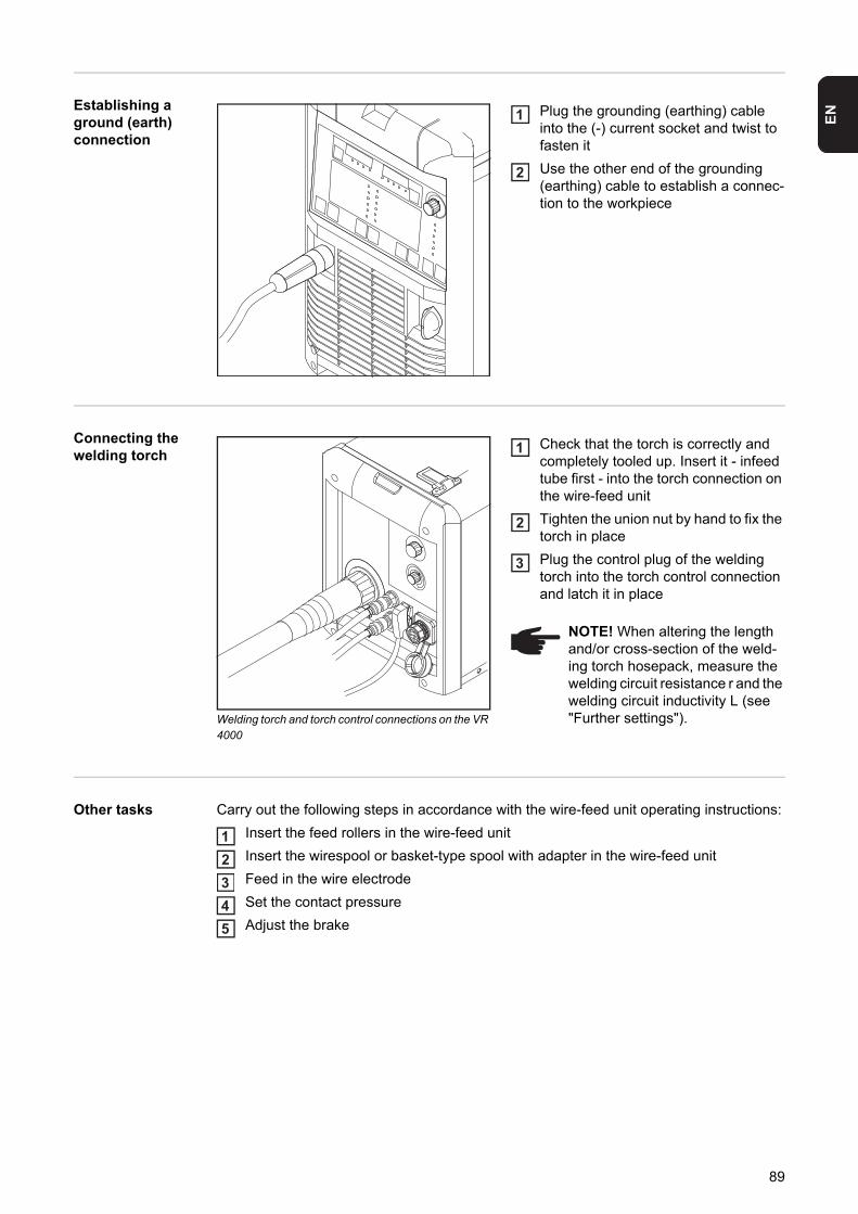
EN
Establishing aground (earth) connection
Plug the grounding (earthing) cable into the (-) current socket and twist to fasten it
Use the other end of the grounding (earthing) cable to establish a connec-tion to the workpiece
Connecting the welding torch
Welding torch and torch control connections on the VR 4000
Check that the torch is correctly and completely tooled up. Insert it - infeed tube first - into the torch connection on the wire-feed unit
Tighten the union nut by hand to fix the torch in place
Plug the control plug of the welding torch into the torch control connection and latch it in place
Other tasks Carry out the following steps in accordance with the wire-feed unit operating instructions:
Insert the feed rollers in the wire-feed unit
Insert the wirespool or basket-type spool with adapter in the wire-feed unit
Feed in the wire electrode
Set the contact pressure
Adjust the brake
1
2
NOTE! When altering the length and/or cross-section of the weld-ing torch hosepack, measure the welding circuit resistance r and the welding circuit inductivity L (see "Further settings").
1
2
3
12345
89
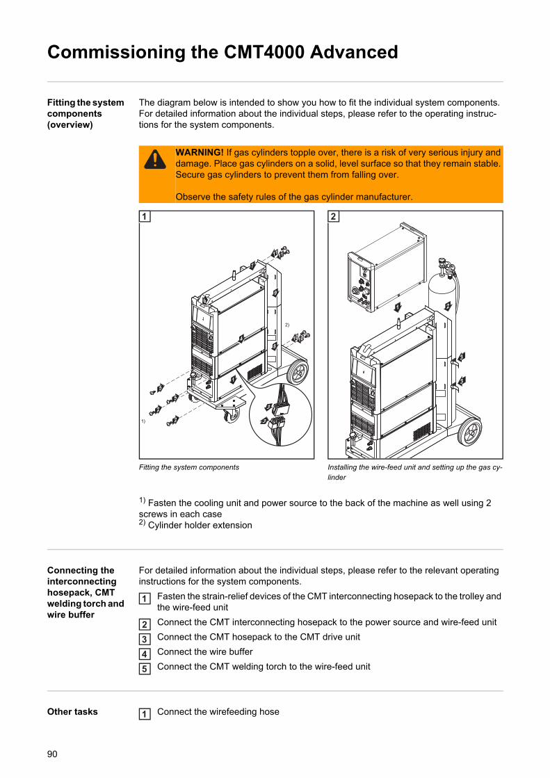
Commissioning the CMT4000 Advanced
Fitting the system components (overview)
The diagram below is intended to show you how to fit the individual system components.For detailed information about the individual steps, please refer to the operating instruc-tions for the system components.
Fitting the system components Installing the wire-feed unit and setting up the gas cy-linder
1) Fasten the cooling unit and power source to the back of the machine as well using 2 screws in each case2) Cylinder holder extension
Connecting the interconnecting hosepack, CMT welding torch and wire buffer
For detailed information about the individual steps, please refer to the relevant operating instructions for the system components.
Fasten the strain-relief devices of the CMT interconnecting hosepack to the trolley and the wire-feed unit
Connect the CMT interconnecting hosepack to the power source and wire-feed unit
Connect the CMT hosepack to the CMT drive unit
Connect the wire buffer
Connect the CMT welding torch to the wire-feed unit
Other tasks Connect the wirefeeding hose
WARNING! If gas cylinders topple over, there is a risk of very serious injury and damage. Place gas cylinders on a solid, level surface so that they remain stable. Secure gas cylinders to prevent them from falling over.
Observe the safety rules of the gas cylinder manufacturer.
11
1
4
7
8
96
5
2
2 3
3
11
1)
2)
1010
5
1
3
1 2
3
2
1
2345
1
90

EN
Establish a ground (earth) connection between the workpiece and power source
Connect the gas cylinder
Connect the RCU 5000i remote control
Make the connection to the robot control
Preparing the wire-feed unit
Carry out the following steps in accordance with the wire-feed unit operating instructions:
Insert the feed rollers in the wire-feed unit
Insert the wirespool or basket-type spool with adapter in the wire-feed unit
Feed in the wire electrode
Set the contact pressure
Adjust the brake
2345
12345
91

92

Welding

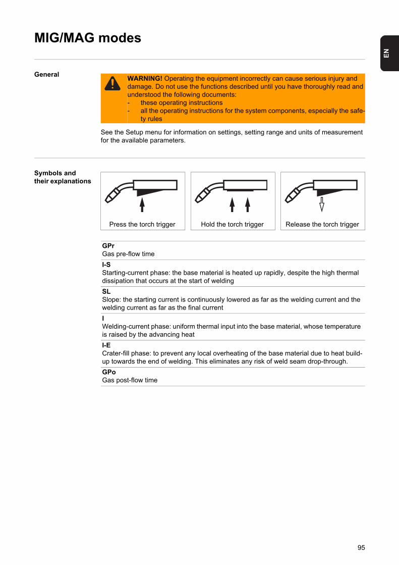
EN
MIG/MAG modes
General
See the Setup menu for information on settings, setting range and units of measurement for the available parameters.
Symbols and their explanations
WARNING! Operating the equipment incorrectly can cause serious injury and damage. Do not use the functions described until you have thoroughly read and understood the following documents:- these operating instructions- all the operating instructions for the system components, especially the safe-
ty rules
Press the torch trigger Hold the torch trigger Release the torch trigger
GPrGas pre-flow time
I-SStarting-current phase: the base material is heated up rapidly, despite the high thermal dissipation that occurs at the start of welding
SLSlope: the starting current is continuously lowered as far as the welding current and the welding current as far as the final current
IWelding-current phase: uniform thermal input into the base material, whose temperature is raised by the advancing heat
I-ECrater-fill phase: to prevent any local overheating of the base material due to heat build-up towards the end of welding. This eliminates any risk of weld seam drop-through.
GPoGas post-flow time
95
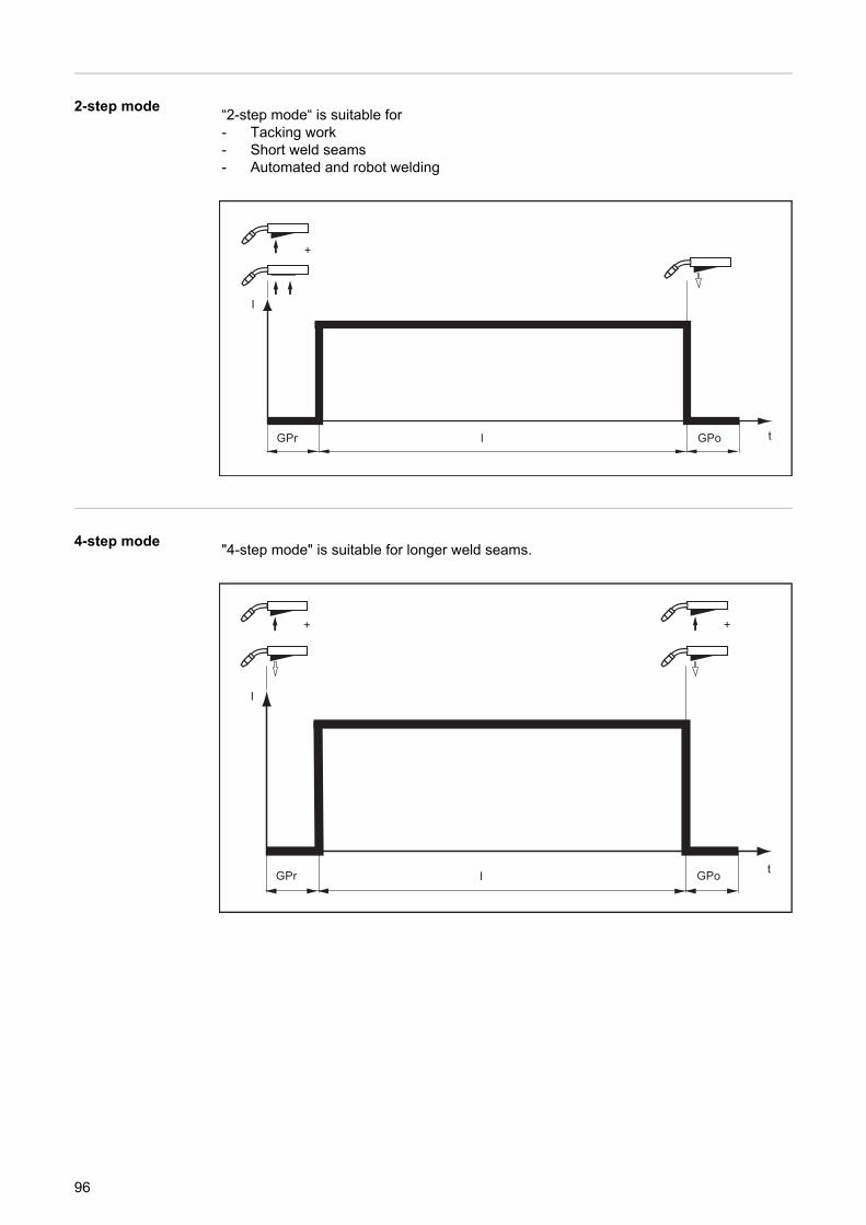
2-step mode
4-step mode
“2-step mode“ is suitable for- Tacking work- Short weld seams- Automated and robot welding
t
I
+
IGPr GPo
"4-step mode" is suitable for longer weld seams.
t
I
+
IGPr GPo
+
96
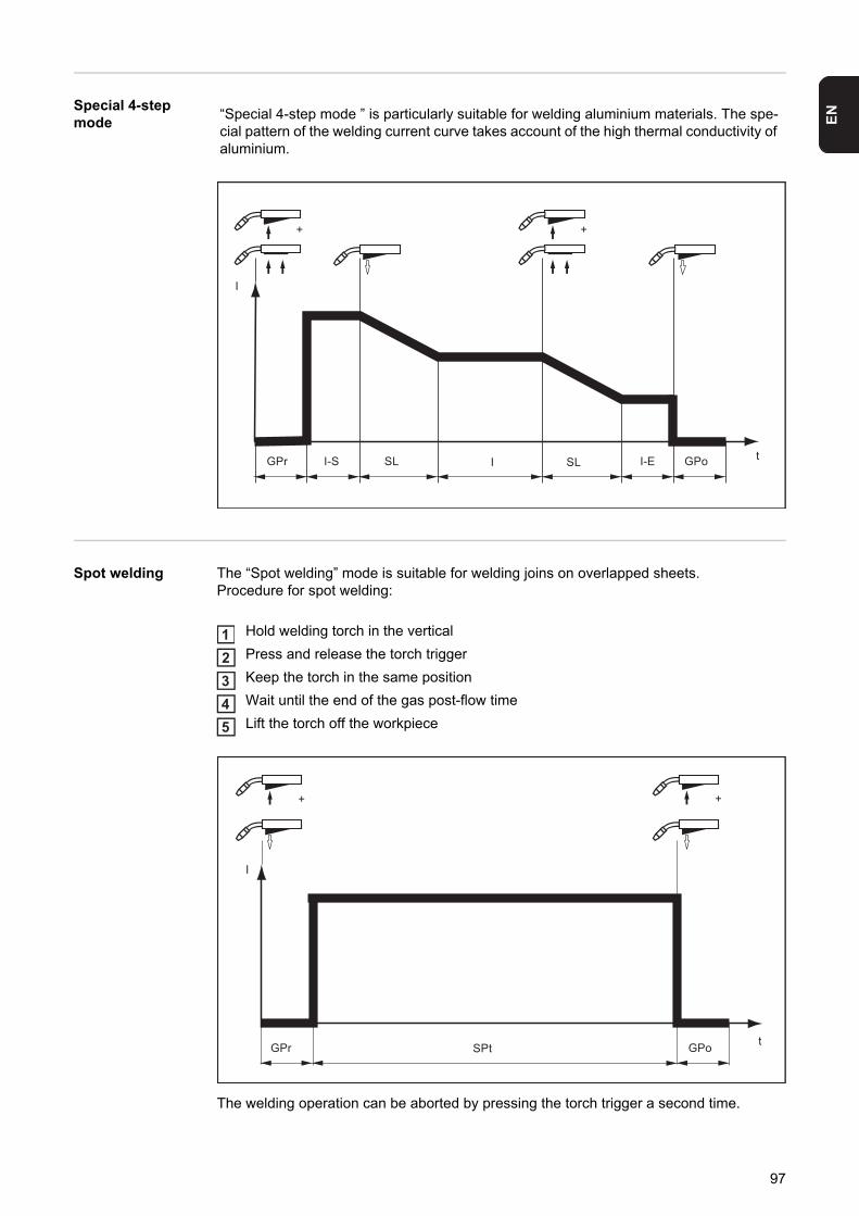
EN
Special 4-stepmode
Spot welding The “Spot welding” mode is suitable for welding joins on overlapped sheets.Procedure for spot welding:
Hold welding torch in the vertical
Press and release the torch trigger
Keep the torch in the same position
Wait until the end of the gas post-flow time
Lift the torch off the workpiece
The welding operation can be aborted by pressing the torch trigger a second time.
“Special 4-step mode ” is particularly suitable for welding aluminium materials. The spe-cial pattern of the welding current curve takes account of the high thermal conductivity of aluminium.
I
tIGPr GPoE-I LSS-I SL
+ +
12345
t
I
+
SPtGPr GPo
+
97
MIG/MAG welding
Safety
General tasks be-fore MIG/MAG welding
Only where a cooling unit and water-cooled welding torch are used:- TPS 2700 with water cooling:
Plug the water hoses of the welding torch to the correct connection sockets on the cooling unit
- TS 4000 / 5000, TPS 3200 / 4000 / 5000 with water cooling:Connect the water hoses of the welding torch to the correct connection sockets on the wire-feed unit
Plug in the mains plug
Move the mains switch to the "I" position:- all the indicators on the control panel light up briefly- where applicable, the cooling unit starts to run
Overview MIG/MAG welding is composed of the following sections:- MIG/MAG synergic welding- MIG/MAG standard manual welding- CMT welding- Special functions and options- Robot welding
WARNING! Operating the equipment incorrectly can cause serious injury and damage. Do not use the functions described until you have thoroughly read and understood the following documents:- these operating instructions- all the operating instructions for the system components, especially the safe-
ty rules
WARNING! An electric shock can be fatal. If the power source is connected to the mains electricity supply during installation, there is a high risk of very serious in-jury and damage. Before carrying out any work on the device make sure that:- the power source mains switch is in the "O" position- the power source is unplugged from the mains
NOTE! Follow the safety rules and note the operating conditions in the cool-ing unit operating instructions.
1
23
98
EN
MIG/MAG synergic welding
General The inputs required for MIG/MAG synergic welding (pulse/standard) are described by ref-erence to the Comfort control panel.
MIG/MAG syner-gic welding
Press the Process button to select the desired welding process: MIG/MAG pulse synergic welding MIG/MAG standard synergic welding
Press the Material button to select the filler metal and shielding gas used
The assignment of SP1 and SP2 depends on the welding database used for the power source.
Press the Wire diameter button to select the diameter of the wire electrode
The assignment of SP depends on the welding database used for the power source.
Press the Mode button to select the desired MIG/MAG mode:
2-step mode 4-step mode Special 4-step mode (aluminium welding start-up) Spot welding
See the Setup menu for details of how to set the parameters for Special 4-step and Spot welding modes.
Press the Parameter selection button to select the welding parameters to be used to specify the welding power:
a-dimension
Sheet thickness
Welding current
Wire feed speed
Use the adjusting dial to set the selected parameter to the desired value. The param-eter value is displayed in the digital display located above it.
The a-dimension, sheet thickness, welding current, wire feed speed and welding volt-age parameters are directly interlinked. It is only necessary to alter one of the param-eters, as the other parameters are immediately adjusted to match.
All welding parameter set values that have been set using the adjusting dial or buttons on the welding torch remain stored until the next time they are changed. This applies even if the power source is switched off and on again in the meantime.
Open the gas cylinder valve
Set the shielding gas flow rate:
Press the Gas test button- Turn the adjusting screw on the underside of the pressure regulator until the pres-
sure gauge shows the required gas flow rate
NOTE! Parameters that have been set on a system component control panel (e.g. wire feed unit or remote control) might not be able to be changed on the power source control panel.
NOTE! Before selecting the a-dimension parameter, the welding speed pa-rameter must be set (recommended welding speed for manual welding:- ap-prox. 35 cm/min or 13.78 ipm).
1
2
3
4
5
6
78
99
Press the torch trigger and start welding
Corrections dur-ing welding
In order to obtain the best possible welding results, the following parameters can be cor-rected in certain circumstances:
The settings for the background parameters gas pre-flow time, gas post-flow time and feeder creep speed are described in the Setup menu.
Adjusting param-eters for correc-tion
Press the Parameter selection button to select the parameter you wish to correct
Use the adjusting dial to set the selected parameter to the desired value. The param-eter value is displayed in the digital display located above it.
Remarks on the Standard control panel
It is not possible to correct the arc length on the Standard control panel.
However, you can set the arc force correction as a background parameter in the Setup menu.
CAUTION! Risk of injury and damage from electric shock and from the wire electrode emerging from the torch. When pressing the torch trigger:
- keep the torch away from your face and body- do not point the welding torch at people- make sure that the wire electrode does not touch any electrically
conducting or earthed (grounded) parts, such as the housing, etc.
9
Arc length correctionfor correcting the arc length
- shorter arc length
0 neutral arc length
+ longer arc length
Droplet detachment correction/arc force dynamic correction/arc force dynam-ic
MIG/MAG pulse synergic welding:for continuous correction of the droplet detachment energy
- lower droplet detachment force
0 neutral droplet detachment force
+ higher droplet detachment force
MIG/MAG standard synergic welding:for influencing the short-circuiting dynamic at the instant of droplet transfer
- harder, more stable arc
0 neutral arc
+ soft, low-spatter arc
Gas pre-flow time
Gas post-flow time
Feeder creep speed
12
100
EN
MIG/MAG standard manual welding
General The MIG/MAG standard manual welding process is a MIG/MAG welding process with no Synergic function.Changing one parameter does not result in any automatic adjustments to the other param-eters. All of the variable parameters must therefore be adjusted individually, as dictated by the welding process in question.
The inputs required for MIG/MAG standard manual welding are described by reference to the "Comfort" control panel.
Available parame-ters
In MIG/MAG standard manual welding, the following parameters are available:
MIG/MAG stand-ard manual weld-ing
Press the Process button to select the MIG/MAG standard manual welding process
Press the Material button to select the filler metal and shielding gas used
The assignment of SP1 and SP2 depends on the welding database used for the power source.
Press the Wire diameter button to select the diameter of the wire electrode
The assignment of SP depends on the welding database used for the power source.
Press the Mode button to select the desired MIG/MAG mode:
2-step mode 4-step mode Special 4-step mode (aluminium welding start-up) Spot welding
In MIG/MAG standard manual welding, special 4-step mode corresponds to conven-tional 4-step mode.
The settings for the parameters for Spot welding mode are described in the Setup menu.
Press the Parameter selection button and select the wire feed speed parameter
Use the adjusting dial to set the desired value for the wire feed speed
Press the Parameter selection button and select the welding voltage parameter
Use the adjusting dial to set the desired value for the welding voltage
The parameter value is displayed in the digital display located above it.
Wire feed speed0.5 m/min (19.69 ipm) - maximum wire feed speede.g. 22.0 m/min (866.14 ipm)
Welding voltageTPS 3200 / 4000 / 5000: 10.0 - 40.0 VTPS 2700: 10.0 - 34.0 V
Dynamic correction for influencing the short-circuiting dynamic at the instant of droplet transfer
Welding currentonly the actual value is displayed
NOTE! Parameters that have been set on a system component control panel (e.g. wire feed unit or remote control) might not be able to be changed on the power source control panel.
1
2
3
4
5678
101
All welding parameter set values that have been set using the adjusting dial or buttons on the welding torch remain stored until the next time they are changed. This is true even if the power source is switched off and on again in the meantime
To display the actual welding current during welding:- press the Parameter selection button and select the welding current parameter- the actual welding current is displayed on the digital display during welding
Open the gas cylinder valve
Set the shielding gas flow rate:
Press the Gas test button- Turn the adjusting screw on the underside of the pressure regulator until the pres-
sure gauge shows the required gas flow rate
Press the torch trigger and start welding
Corrections dur-ing welding
In order to obtain the best possible welding results, the following parameters can be cor-rected in certain circumstances:
The settings for the background parameters gas pre-flow time, gas post-flow time and feeder creep speed are described in the Setup menu.
Adjusting param-eters for correc-tion
Press the Parameter selection button to select the parameter you wish to correct
Use the adjusting dial to set the selected parameter to the desired value. The param-eter value is displayed in the digital display located above it.
CAUTION! Risk of injury and damage from electric shock and from the wire electrode emerging from the torch. When pressing the torch trigger:
- keep the torch away from your face and body- do not point the welding torch at people- make sure that the wire electrode does not touch any electrically
conducting or earthed (grounded) parts, such as the housing, etc.
910
1111
Dynamic correctionfor influencing the short-circuiting dynamic at the instant of droplet transfer
0 harder, more stable arc
10 soft, low-spatter arc
Gas pre-flow time
Gas post-flow time
Feeder creep speed
12
102
EN
CMT welding
General The inputs required for CMT welding are described by reference to the CMT control panel.Settings for CMT applications with the CMT remote power source and the RCU 5000i re-mote control can be found in the operating instructions for the RCU 5000i remote control.
CMT welding Press the Process button to select the CMT/CMT pulse process:
Press the Material button to select the filler metal and shielding gas used
Press the Wire diameter button to select the diameter of the wire electrode
The assignment of SP depends on the welding database used for the power source.
Press the Mode button to select the desired MIG/MAG mode:
2-step mode 4-step mode Special 4-step mode (aluminium welding start-up) Spot welding
See the Setup menu for details of how to set the parameters for Special 4-step and Spot welding modes.
Press the Parameter selection button to select the welding parameters to be used to specify the welding power:
Sheet thickness
Welding current
Wire feed speed
Filler metals for CMT welding:
1 ER 70 S-3/6 Steel
3 ER 308 CrNi 19 9
5 ER 4043 AlSi 5
6 ER CuSi-A CuSi 3
8 SP 1 1)
10 Steel ER 70 S-3/6
12 CrNi 19 9 ER 308
14 AlSi 5 ER 4043
15 CuSi 3 ER CuSi-A
16 SP 2 1)
To weld the other filler metals, select one of the following processes: MIG/MAG pulse synergic welding MIG/MAG standard synergic welding MIG/MAG standard manual welding
1) The assignment of SP1 and SP2 depends on the welding database used for the pow-er source.
NOTE! Parameters that have been set on a system component control panel (e.g. wire feed unit or remote control) might not be able to be changed on the power source control panel.
1
2
3
4
5
103
Use the adjusting dial to set the selected parameter to the desired value. The param-eter value is displayed in the digital display located above it.
The sheet thickness, welding current, wire feed speed and welding voltage parame-ters are directly interlinked. It is only necessary to alter one of the parameters, as the other parameters are immediately adjusted to match.
All welding parameter set values that have been set using the adjusting dial or buttons on the welding torch remain stored until the next time they are changed. This applies even if the power source is switched off and on again in the meantime.
Open the gas cylinder valve
Set the shielding gas flow rate:
Press the Purge (Gas test) button- Turn the adjusting screw on the underside of the pressure regulator until the pres-
sure gauge shows the required gas flow rate
Press the torch trigger and start welding
Corrections dur-ing welding
In order to obtain the best possible welding results, the following parameters can be cor-rected in certain circumstances:
CAUTION! Risk of injury and damage from electric shock and from the wire electrode emerging from the torch. When pressing the torch trigger:
- keep the torch away from your face and body- do not point the welding torch at people- make sure that the wire electrode does not touch any electrically
conducting or earthed (grounded) parts, such as the housing, etc.
6
78
9
Arc length correctionfor correcting the arc length
- shorter arc length
0 neutral arc length
+ longer arc length
Droplet detachment correction/arc force dynamic correction/arc force dynam-icdepending on the selected filler metal and wire electrode diameter, different settings are corrected with this parameter:
Boost correctionsets the boost current for controlling the heat input to the base material
-5 maximum boost current
0 neutral boost current
+5 maximum boost current
The boost current can be corrected for the following filler metals:- CrNi 19 9 / Ar + 2.5 % CO2 / 1.2 mm- CuSi 3 / 100 % Ar / 0.8 mm- CuSi 3 / 100 % Ar / 1.0 mm- CuSi 3 / 100 % Ar / 1.2 mm
Dynamic correctionfor influencing the short-circuiting dynamic at the instant of droplet transfer
-5 harder, more stable arc
0 neutral arc
104
EN
The settings for the background parameters gas pre-flow time, gas post-flow time and feeder creep speed are described in the Setup menu.
+5 soft, low-spatter arc
The arc force dynamic can be corrected with the following filler metals:- G3Si 1 / Ar + 18 % CO2 / 1.0 mm- G3Si 1 / Ar + 18 % CO2 / 1.2 mm
HotStart pulse cyclesfor setting the HotStart pulse cycles
-5 0 pulses
+5 100 pulses
The HotStart pulse cycles can be corrected with the following filler metals:- AlMg 4.5 Mn / 100 % Ar / 1.2 mm (CMT 0875)
HotStart timefor setting the HotStart time
-5 HotStart time = 0
+5 HotStart time = 200 ms
The HotStart pulse cycles can be corrected with the following filler metals:- AlMg 4.5 Mn / 100 % Ar / 1.2 mm (CMT 0874)1)
- AlSi 5 / 100% Ar / 1.2 mm- CrNi 19 9 / Ar + 2.5 % CO2 / 0.8 mm- CrNi 19 9 / Ar + 2.5 % CO2 / 1.0 mm- CuAl 5 Ni 2 / 100 % Ar / 1.0 mm
Pulse correctionfor continuous correction of the droplet detachment energy
-5 lower droplet detachment force
0 neutral droplet detachment force
+5 higher droplet detachment force
The pulse can be corrected with the following filler metals:- AlMg 4.5 Mn / 100% Ar / 1.2 mm 2)
- AlSi 5 / 100 % Ar / 1.2 mm (CMT 0880) 2) 3)
- AlSi 5 / 100 % Ar / 1.2 mm (CMT 0881) 2) 4)
- CrNi 19 9 / Ar + 2.5 % CO2 / 0.8 mm 2)
- CrNi 19 9 / Ar + 2.5 % CO2 / 1.0 mm 2)
- CrNi 19 9 / Ar + 2.5 % CO2 / 1.2 mm 2)
- CuAl 8 / 100 % Ar / 1.0 mm 2)
- CuSi 3 / 100 % Ar / 1.0 mm 2)
Notes1) Different ignition process from the CMT 0875 characteristic2) Combination of CMT characteristic and pulse characteristic3) CMT/pulse characteristic with more pulse cycles than CMT cycles4) CMT/pulse characteristic with fewer pulse cycles than CMT cycles
Gas pre-flow time
Gas post-flow time
Feeder creep speed
105

Adjusting param-eters for correc-tion
Press the Parameter selection button to select the parameter you wish to correct
Use the adjusting dial to set the selected parameter to the desired value. The param-eter value is displayed in the digital display located above it.
12
106
EN
Special functions and options
Arc break watch-dog function
If the arc breaks and no current starts to flow again within a time defined in the Setup menu, the system cuts out automatically. The service code "no | Arc" appears on the control pan-el.
To start welding again, press the torch trigger again.
In the factory settings, the arc break watchdog function (Arc) is set to OFF.
The settings for the arc break watchdog parameter (Arc) are described in "Setup menu - level 2".
Ignition time-out function
The power source has the Ignition time-out function. This function is not factory-activated as standard.
Once the torch trigger is pressed, gas pre-flow begins immediately. Wire feeding then be-gins, followed by ignition. If no current starts flowing before the length of wire specified in the Setup menu has been fed, the power source cuts out automatically. The service code "no | IGn" appears on the control panel.
“E55” is displayed on the JobMaster torch and on the field bus module.
To make another attempt to achieve ignition, press the torch trigger again.
The settings for the Ignition time-out parameter (ito) are described in the "Setup-menu-lev-el 2" section.
Spatter-free igni-tion option
The spatter free ignition option (SFi) makes it possible to ignite the arc with practically no spatter. At the beginning of welding, the wire is slowly fed as far as the surface of the work-piece and then stopped as soon as it touches it. Next, the welding current is activated and the wire is pulled back. Once the correct arc length has been reached, the wire starts being fed at the speed specified for this welding process.
System requirements:- Firmware version on the power source: OFFICIAL UST V2.60.1- Firmware version on the wire-feed unit: OFFICIAL SR41 V1.40.15
NOTE! At maximum welding current and very low arc length it is possible that the arc will break without the service code “no | Arc” appearing. If the arc is reduced significantly, the welding current would have to be increased to more than the maximum current in order to be able to maintain the requested welding power. As this is not acceptable, the power source switches off for safety reasons.
NOTE! The optimum function of the spatter-free ignition option can only be guar-anteed in aluminium applications in conjunction with Fronius push-pull wire-feed unit systems.
NOTE! External enabling of the spatter-free ignition option is possible from firmware version OFFICIAL UST V2.70.1 (power source) upwards. At present, this option only supports aluminium wires of diameters:- 0.8 mm / 1.0 mm / 1.2 mm / 1.6 mm- USA: 0.9 mm (0.035 in.) / 1.2 mm (0.045 in) / 1.6 mm (1/16 in.)
107
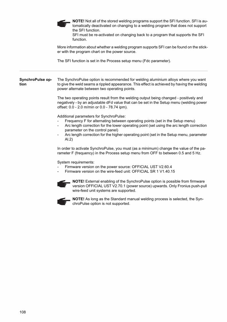
More information about whether a welding program supports SFI can be found on the stick-er with the program chart on the power source.
The SFI function is set in the Process setup menu (Fdc parameter).
SynchroPulse op-tion
The SynchroPulse option is recommended for welding aluminium alloys where you want to give the weld seams a rippled appearance. This effect is achieved by having the welding power alternate between two operating points.
The two operating points result from the welding output being changed - positively and negatively - by an adjustable dFd value that can be set in the Setup menu (welding power offset: 0.0 - 2.0 m/min or 0.0 - 78.74 ipm).
Additional parameters for SynchroPulse:- Frequency F for alternating between operating points (set in the Setup menu)- Arc length correction for the lower operating point (set using the arc length correction
parameter on the control panel)- Arc length correction for the higher operating point (set in the Setup menu, parameter
Al.2)
In order to activate SynchroPulse, you must (as a minimum) change the value of the pa-rameter F (frequency) in the Process setup menu from OFF to between 0.5 and 5 Hz.
System requirements:- Firmware version on the power source: OFFICIAL UST V2.60.4- Firmware version on the wire-feed unit: OFFICIAL SR 1 V1.40.15
NOTE! Not all of the stored welding programs support the SFI function. SFI is au-tomatically deactivated on changing to a welding program that does not support the SFI function.SFI must be re-activated on changing back to a program that supports the SFI function.
NOTE! External enabling of the SynchroPulse option is possible from firmware version OFFICIAL UST V2.70.1 (power source) upwards. Only Fronius push-pull wire-feed unit systems are supported.
NOTE! As long as the Standard manual welding process is selected, the Syn-chroPulse option is not supported.
108
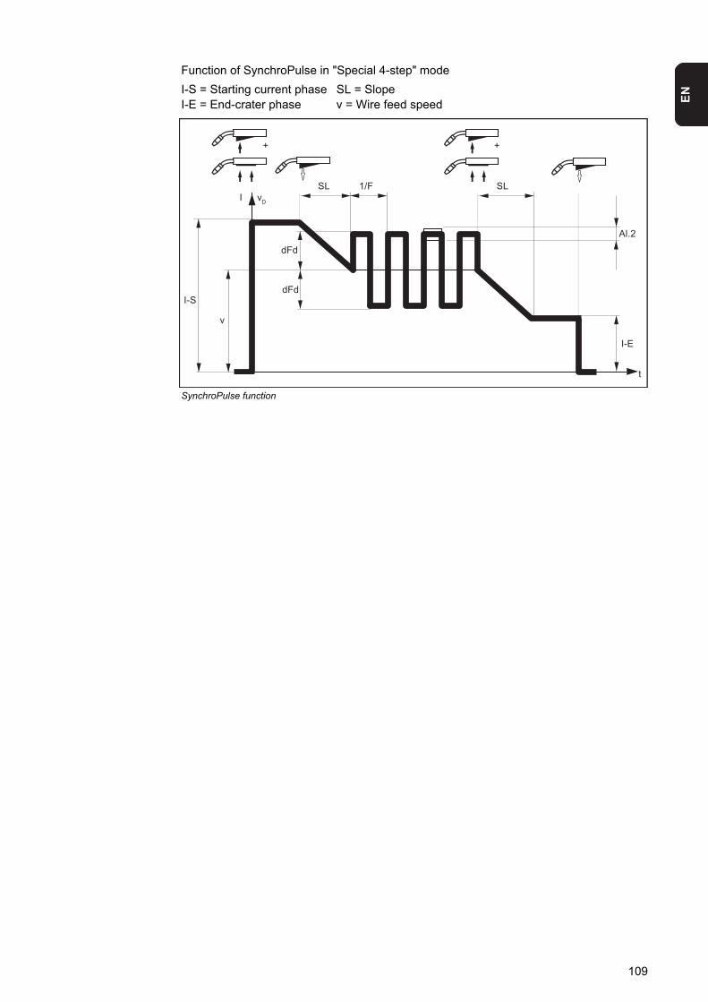
EN
Function of SynchroPulse in "Special 4-step" mode
I-S = Starting current phase SL = SlopeI-E = End-crater phase v = Wire feed speed
SynchroPulse function
I vD
Al.2
LSLS
+ +
dFd
1/F
v
I-SdFd
t
I-E
109
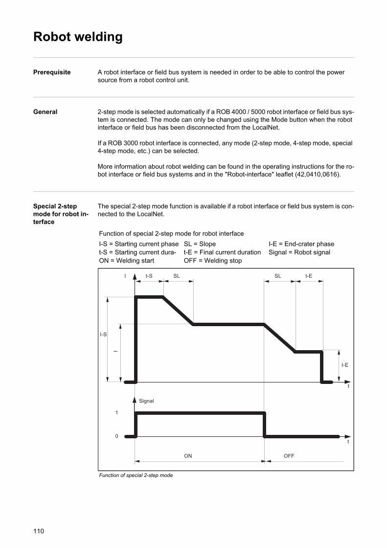
Robot welding
Prerequisite A robot interface or field bus system is needed in order to be able to control the power source from a robot control unit.
General 2-step mode is selected automatically if a ROB 4000 / 5000 robot interface or field bus sys-tem is connected. The mode can only be changed using the Mode button when the robot interface or field bus has been disconnected from the LocalNet.
If a ROB 3000 robot interface is connected, any mode (2-step mode, 4-step mode, special 4-step mode, etc.) can be selected.
More information about robot welding can be found in the operating instructions for the ro-bot interface or field bus systems and in the "Robot-interface" leaflet (42,0410,0616).
Special 2-step mode for robot in-terface
The special 2-step mode function is available if a robot interface or field bus system is con-nected to the LocalNet.
Function of special 2-step mode for robot interface
I-S = Starting current phase SL = Slope I-E = End-crater phaset-S = Starting current dura- t-E = Final current duration Signal = Robot signalON = Welding start OFF = Welding stop
Function of special 2-step mode
Signal
0
1
I
I-S
I-E
E-tLSLSS-t
I
t
t
OFFON
110
EN
Wire-stick controlfunctionThe wire-stick control function is available if a robot interface or field bus system is con-nected to the LocalNet.
After the end of welding, the wire-stick control function detects any “sticking” of the wire electrode in the solidifying weld pool. If a sticking wire electrode is detected within 750 ms after the end of welding, the error message “Err | 054” will be output.
Procedure in the event of a sticking wire electrode:
Cut off the end of the wire electrode that is sticking
The power source is now ready for operation.
Changing the welding process during CMT Ad-vanced welding To change the welding process or characteristic:
first, end the CMT Advanced process
wait 300 - 600 msAnother welding process or characteristic can be selected during this time.
Resume the welding process with another welding process or characteristic
WARNING! A welding process that starts automatically can pose a risk to life. The “Arc on” signal must not be set while the error is being rectified, otherwise welding will start as soon as the error is rectified.
NOTE! The error message “Err | 054” does not need to be acknowledged.
NOTE! The standard factory setting is that the wire-stick control function is not ac-tivated. If required, activate the wire-stick control function in the "Setup menu - level 2" (“Stc | ON”).
1
NOTE! Neither the welding process nor the currently selected characteristic can be changed during CMT Advanced welding.
12
3
111
TIG welding
Safety
Prerequisite The TIG welding process is only possible- with the Comfort, US and TIME 5000 Digital control panels- with a TIG gas valve torch
The inputs required for TIG welding are described by reference to the Comfort control pan-el.
Preparation Move the mains switch to the "O" position
Disconnect the mains plug
Remove the MIG/MAG welding torch
Disconnect the grounding (earthing) cable from the (-) current socket
Plug the grounding (earthing) cable into the (+) current socket and latch it in place
Use the other end of the grounding (earthing) cable to establish a connection to the workpiece
Plug the bayonet current plug on the TIG gas valve torch into the (-) current socket and twist it clockwise to fasten it
Screw the pressure regulator onto the (argon) gas cylinder and tighten it
Connect the gas hose of the TIG gas valve torch to the pressure regulator
Plug in the mains plug
TIG welding
Move the mains switch to the "I" position: all the indicators on the control panel light up briefly
Press the Process button to select the TIG welding process:
The welding voltage is connected to the welding socket with a 3-second time lag.
WARNING! Operating the equipment incorrectly can cause serious injury and damage. Do not use the functions described until you have thoroughly read and understood the following documents:- these operating instructions- all the operating instructions for the system components, especially the safe-
ty rules
WARNING! An electric shock can be fatal. If the power source is connected to the mains electricity supply during installation, there is a high risk of very serious in-jury and damage. Before carrying out any work on the device make sure that:- the power source mains switch is in the "O" position- the power source is unplugged from the mains
123456
7
89
10
CAUTION! Risk of injury and damage from electric shock. As soon as the mains switch is in the "I" position, the tungsten electrode of the welding torch is LIVE. Make sure that the tungsten electrode does not touch any persons or electrically conducting or earthed parts (e.g. housing, etc.)
1
2
112
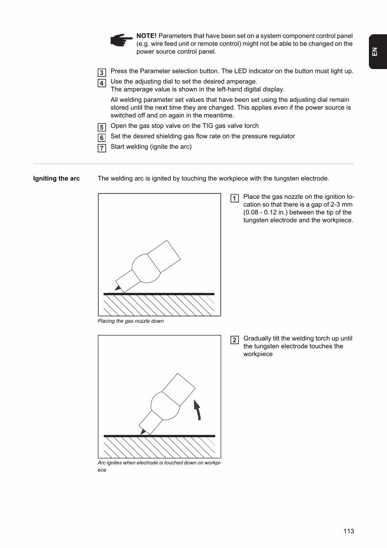
EN
Press the Parameter selection button. The LED indicator on the button must light up.
Use the adjusting dial to set the desired amperage.The amperage value is shown in the left-hand digital display.
All welding parameter set values that have been set using the adjusting dial remain stored until the next time they are changed. This applies even if the power source is switched off and on again in the meantime.
Open the gas stop valve on the TIG gas valve torch
Set the desired shielding gas flow rate on the pressure regulator
Start welding (ignite the arc)
Igniting the arc The welding arc is ignited by touching the workpiece with the tungsten electrode.
Placing the gas nozzle down
Place the gas nozzle on the ignition lo-cation so that there is a gap of 2-3 mm (0.08 - 0.12 in.) between the tip of the tungsten electrode and the workpiece.
Arc ignites when electrode is touched down on workpi-ece
Gradually tilt the welding torch up until the tungsten electrode touches the workpiece
NOTE! Parameters that have been set on a system component control panel (e.g. wire feed unit or remote control) might not be able to be changed on the power source control panel.
34
567
1
2
113
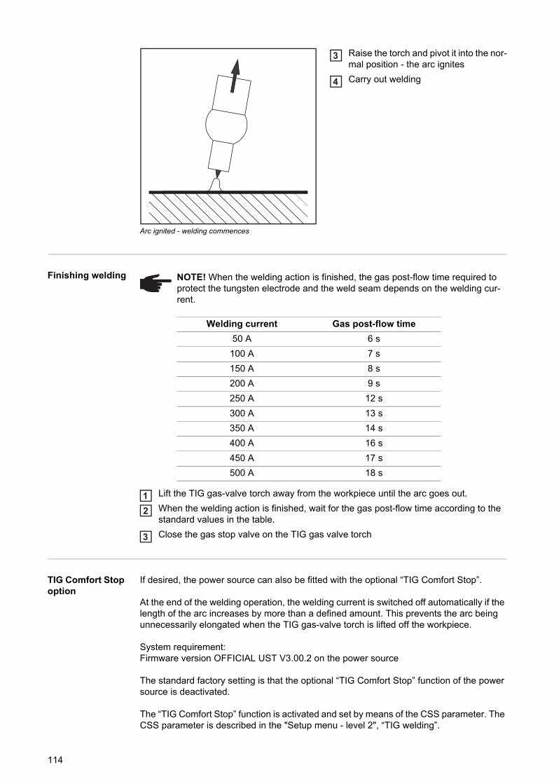
Arc ignited - welding commences
Raise the torch and pivot it into the nor-mal position - the arc ignites
Carry out welding
Finishing welding
Lift the TIG gas-valve torch away from the workpiece until the arc goes out.
When the welding action is finished, wait for the gas post-flow time according to the standard values in the table.
Close the gas stop valve on the TIG gas valve torch
TIG Comfort Stop option
If desired, the power source can also be fitted with the optional “TIG Comfort Stop”.
At the end of the welding operation, the welding current is switched off automatically if the length of the arc increases by more than a defined amount. This prevents the arc being unnecessarily elongated when the TIG gas-valve torch is lifted off the workpiece.
System requirement:Firmware version OFFICIAL UST V3.00.2 on the power source
The standard factory setting is that the optional “TIG Comfort Stop” function of the power source is deactivated.
The “TIG Comfort Stop” function is activated and set by means of the CSS parameter. The CSS parameter is described in the "Setup menu - level 2", “TIG welding”.
3
4
NOTE! When the welding action is finished, the gas post-flow time required to protect the tungsten electrode and the weld seam depends on the welding cur-rent.
Welding current Gas post-flow time
50 A 6 s
100 A 7 s
150 A 8 s
200 A 9 s
250 A 12 s
300 A 13 s
350 A 14 s
400 A 16 s
450 A 17 s
500 A 18 s
12
3
114
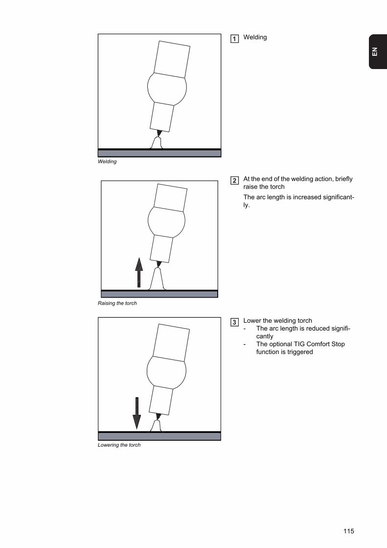
EN
Welding
Welding
Raising the torch
At the end of the welding action, briefly raise the torch
The arc length is increased significant-ly.
Lowering the torch
Lower the welding torch- The arc length is reduced signifi-
cantly- The optional TIG Comfort Stop
function is triggered
1
2
3
115
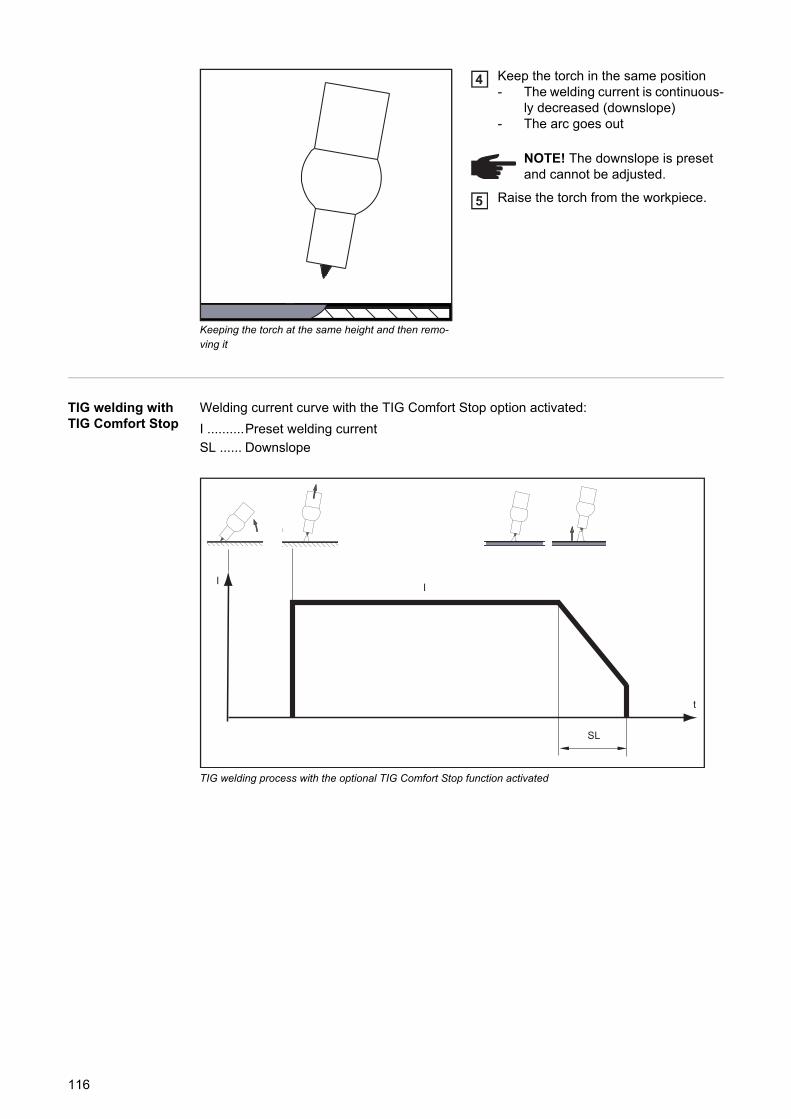
Keeping the torch at the same height and then remo-ving it
Keep the torch in the same position- The welding current is continuous-
ly decreased (downslope)- The arc goes out
Raise the torch from the workpiece.
TIG welding with TIG Comfort Stop
Welding current curve with the TIG Comfort Stop option activated:
I ..........Preset welding current
SL ...... Downslope
TIG welding process with the optional TIG Comfort Stop function activated
NOTE! The downslope is preset and cannot be adjusted.
4
5
I
t
I
SL
116
EN
MMA welding
Safety
Prerequisite Manual metal arc (MMA) welding is only possible in conjunction with the Comfort, US, TIME 5000 Digital and CMT control panels.
The inputs required for MMA welding are described by reference to the Comfort control panel.
Preparation Move the mains switch to the "O" position
Disconnect the mains plug
Remove the MIG/MAG welding torch
Plug the grounding (earthing) cable into either the (-) or the (+) current socket, depend-ing on the type of electrode, and latch it in firmly
Use the other end of the grounding (earthing) cable to establish a connection to the workpiece
Plug the bayonet current plug of the electrode holder cable into the free current socket with the opposite polarity, according to the type of electrode, and twist it clockwise to latch it in place
Plug in the mains plug
Manual metal arc welding
Move the mains switch to the "I" position: all the indicators on the control panel light up briefly
Press the Process button to select the MMA welding process:
The welding voltage is connected to the welding socket with a 3-second time lag.
If the MMA welding process is selected, any cooling unit present is automatically de-activated. It is not possible to switch it on.
WARNING! Operating the equipment incorrectly can cause serious injury and damage. Do not use the functions described until you have thoroughly read and understood the following documents:- these operating instructions- all the operating instructions for the system components, especially the safe-
ty rules
WARNING! An electric shock can be fatal. If the power source is connected to the mains electricity supply during installation, there is a high risk of very serious in-jury and damage. Before carrying out any work on the device make sure that:- the power source mains switch is in the "O" position- the power source is unplugged from the mains
NOTE! Check the rod electrode packaging to determine whether the rod electrodes are for (+) or (-) welding.
123
4
5
6
7
CAUTION! Risk of injury and damage from electric shock. As soon as the mains switch is in the "I" position, the rod electrode in the electrode holder is LIVE. Make sure that the rod electrode does not touch any persons or electrically conducting or earthed parts (e.g. the housing etc.).
1
2
117
Press the Parameter selection button. The LED indicator on the button must light up.
Use the adjusting dial to set the desired amperage.The amperage value is shown in the left-hand digital display.
All welding parameter set values that have been set using the adjusting dial remain stored until the next time they are changed. This applies even if the power source is switched off and on again in the meantime.
Start welding
Corrections dur-ing welding
Adjusting param-eters for correc-tion
Press the Parameter selection button to select the parameter you wish to correct
Use the adjusting dial to set the selected parameter to the desired value. The param-eter value is displayed in the digital display located above it.
HotStart function To obtain optimum welding results, it will sometimes be necessary to adjust the HotStart function.Benefits- Improved ignition, even when using electrodes with poor ignition properties- Better fusion of the base material during start-up phase, meaning fewer cold-shut de-
fects- Largely prevents slag inclusions
See the "Setup menu: level 2" section for details on setting the available welding parame-ters.
NOTE! Parameters that have been set on a system component control panel (e.g. wire feed unit or remote control) might not be able to be changed on the power source control panel.
NOTE! The power source has a pulsating open circuit voltage. When the MMA welding process is selected, the right hand digital display shows an average weld-ing voltage value of 40 V before welding begins (open circuit). The following max-imum welding voltages are available for the welding start and the welding process to ensure optimum ignition properties:- TPS 2700 ... 50 V- TS 4000 / 5000, TPS 3200 / 4000 / 5000 ... 70 V
34
5
In order to obtain the best possible welding results, the following parameter can be cor-rected in certain circumstances:
Arc-force dynamicto influence the short-circuiting dynamic at the instant of droplet transfer
0 soft, low-spatter arc
100 harder, more stable arc
12
118
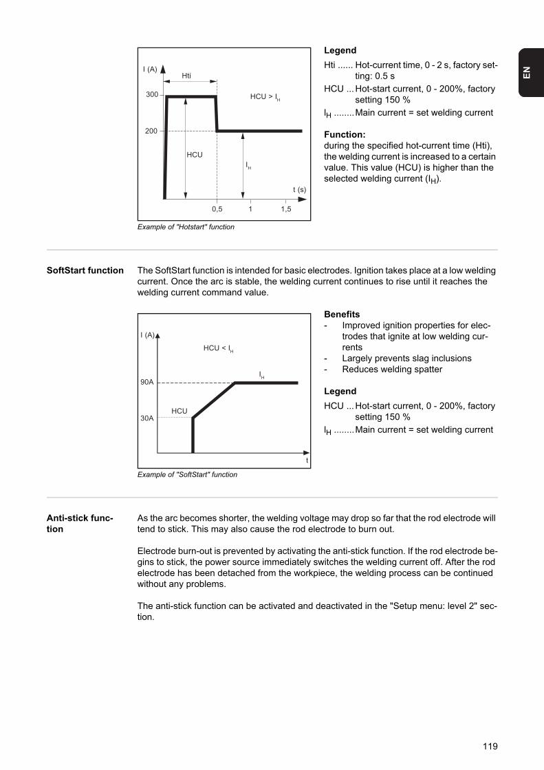
EN
Example of "Hotstart" function
Legend
Hti ...... Hot-current time, 0 - 2 s, factory set-ting: 0.5 s
HCU ...Hot-start current, 0 - 200%, factory setting 150 %
lH ........Main current = set welding current
Function:during the specified hot-current time (Hti), the welding current is increased to a certain value. This value (HCU) is higher than the selected welding current (IH).
SoftStart function The SoftStart function is intended for basic electrodes. Ignition takes place at a low welding current. Once the arc is stable, the welding current continues to rise until it reaches the welding current command value.
Example of "SoftStart" function
Benefits- Improved ignition properties for elec-
trodes that ignite at low welding cur-rents
- Largely prevents slag inclusions- Reduces welding spatter
Legend
HCU ...Hot-start current, 0 - 200%, factory setting 150 %
lH ........Main current = set welding current
Anti-stick func-tion
As the arc becomes shorter, the welding voltage may drop so far that the rod electrode will tend to stick. This may also cause the rod electrode to burn out.
Electrode burn-out is prevented by activating the anti-stick function. If the rod electrode be-gins to stick, the power source immediately switches the welding current off. After the rod electrode has been detached from the workpiece, the welding process can be continued without any problems.
The anti-stick function can be activated and deactivated in the "Setup menu: level 2" sec-tion.
I (A)
t (s)
0,5 1 1,5
Hti
IH
HCU
200
300 HCU > IH
I (A)
t
90A
30A
IH
HCU
HCU < IH
119
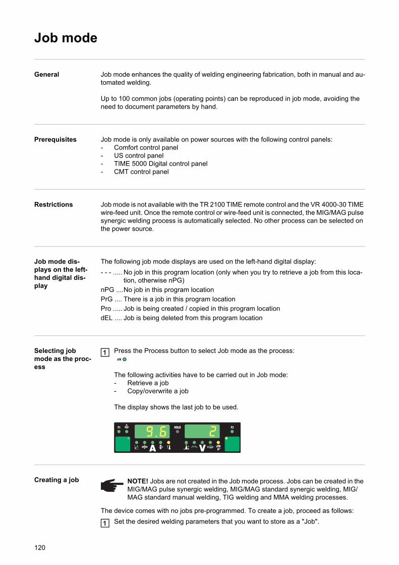
Job mode
General Job mode enhances the quality of welding engineering fabrication, both in manual and au-tomated welding.
Up to 100 common jobs (operating points) can be reproduced in job mode, avoiding the need to document parameters by hand.
Prerequisites Job mode is only available on power sources with the following control panels:- Comfort control panel- US control panel- TIME 5000 Digital control panel- CMT control panel
Restrictions Job mode is not available with the TR 2100 TIME remote control and the VR 4000-30 TIME wire-feed unit. Once the remote control or wire-feed unit is connected, the MIG/MAG pulse synergic welding process is automatically selected. No other process can be selected on the power source.
Job mode dis-plays on the left-hand digital dis-play
The following job mode displays are used on the left-hand digital display:
- - - ..... No job in this program location (only when you try to retrieve a job from this loca-tion, otherwise nPG)
nPG ....No job in this program location
PrG .... There is a job in this program location
Pro ..... Job is being created / copied in this program location
dEL .... Job is being deleted from this program location
Selecting job mode as the proc-ess
Press the Process button to select Job mode as the process:
The following activities have to be carried out in Job mode:- Retrieve a job- Copy/overwrite a job
The display shows the last job to be used.
Creating a job
The device comes with no jobs pre-programmed. To create a job, proceed as follows:
Set the desired welding parameters that you want to store as a "Job".
1
NOTE! Jobs are not created in the Job mode process. Jobs can be created in the MIG/MAG pulse synergic welding, MIG/MAG standard synergic welding, MIG/MAG standard manual welding, TIG welding and MMA welding processes.
1
120
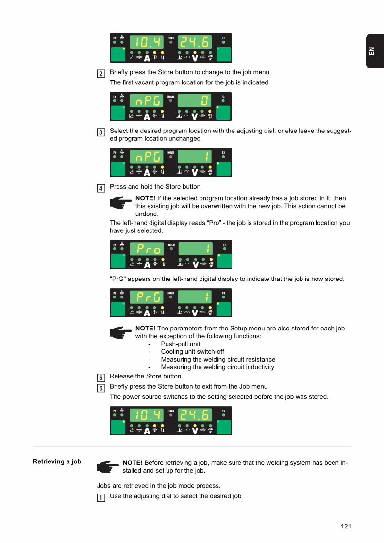
EN
Briefly press the Store button to change to the job menu
The first vacant program location for the job is indicated.
Select the desired program location with the adjusting dial, or else leave the suggest-ed program location unchanged
Press and hold the Store button
The left-hand digital display reads “Pro” - the job is stored in the program location you have just selected.
"PrG" appears on the left-hand digital display to indicate that the job is now stored.
Release the Store button
Briefly press the Store button to exit from the Job menu
The power source switches to the setting selected before the job was stored.
Retrieving a job
Jobs are retrieved in the job mode process.
Use the adjusting dial to select the desired job
2
3
NOTE! If the selected program location already has a job stored in it, then this existing job will be overwritten with the new job. This action cannot be undone.
4
NOTE! The parameters from the Setup menu are also stored for each job with the exception of the following functions:
- Push-pull unit- Cooling unit switch-off- Measuring the welding circuit resistance- Measuring the welding circuit inductivity
56
NOTE! Before retrieving a job, make sure that the welding system has been in-stalled and set up for the job.
1
121
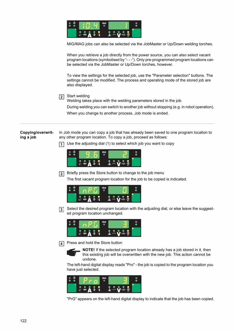
MIG/MAG jobs can also be selected via the JobMaster or Up/Down welding torches.
When you retrieve a job directly from the power source, you can also select vacant program locations (symbolised by “- - -”). Only pre-programmed program locations can be selected via the JobMaster or Up/Down torches, however.
To view the settings for the selected job, use the "Parameter selection" buttons. The settings cannot be modified. The process and operating mode of the stored job are also displayed.
Start weldingWelding takes place with the welding parameters stored in the job.
During welding you can switch to another job without stopping (e.g. in robot operation).
When you change to another process, Job mode is ended.
Copying/overwrit-ing a job
In Job mode you can copy a job that has already been saved to one program location to any other program location. To copy a job, proceed as follows:
Use the adjusting dial (1) to select which job you want to copy
Briefly press the Store button to change to the job menu
The first vacant program location for the job to be copied is indicated.
Select the desired program location with the adjusting dial, or else leave the suggest-ed program location unchanged.
Press and hold the Store button
The left-hand digital display reads "Pro" - the job is copied to the program location you have just selected.
"PrG" appears on the left-hand digital display to indicate that the job has been copied.
2
1
2
3
NOTE! If the selected program location already has a job stored in it, then this existing job will be overwritten with the new job. This action cannot be undone.
4
122
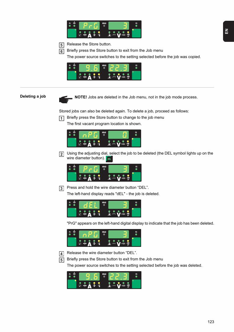
EN
Release the Store button.
Briefly press the Store button to exit from the Job menu
The power source switches to the setting selected before the job was copied.
Deleting a job
Stored jobs can also be deleted again. To delete a job, proceed as follows:
Briefly press the Store button to change to the job menu
The first vacant program location is shown.
Using the adjusting dial, select the job to be deleted (the DEL symbol lights up on the wire diameter button).
Press and hold the wire diameter button “DEL”.
The left-hand display reads "dEL" - the job is deleted.
"PrG" appears on the left-hand digital display to indicate that the job has been deleted.
Release the wire diameter button “DEL”.
Briefly press the Store button to exit from the Job menu
The power source switches to the setting selected before the job was deleted.
56
NOTE! Jobs are deleted in the Job menu, not in the job mode process.
1
2
3
45
123

124

Setup settings

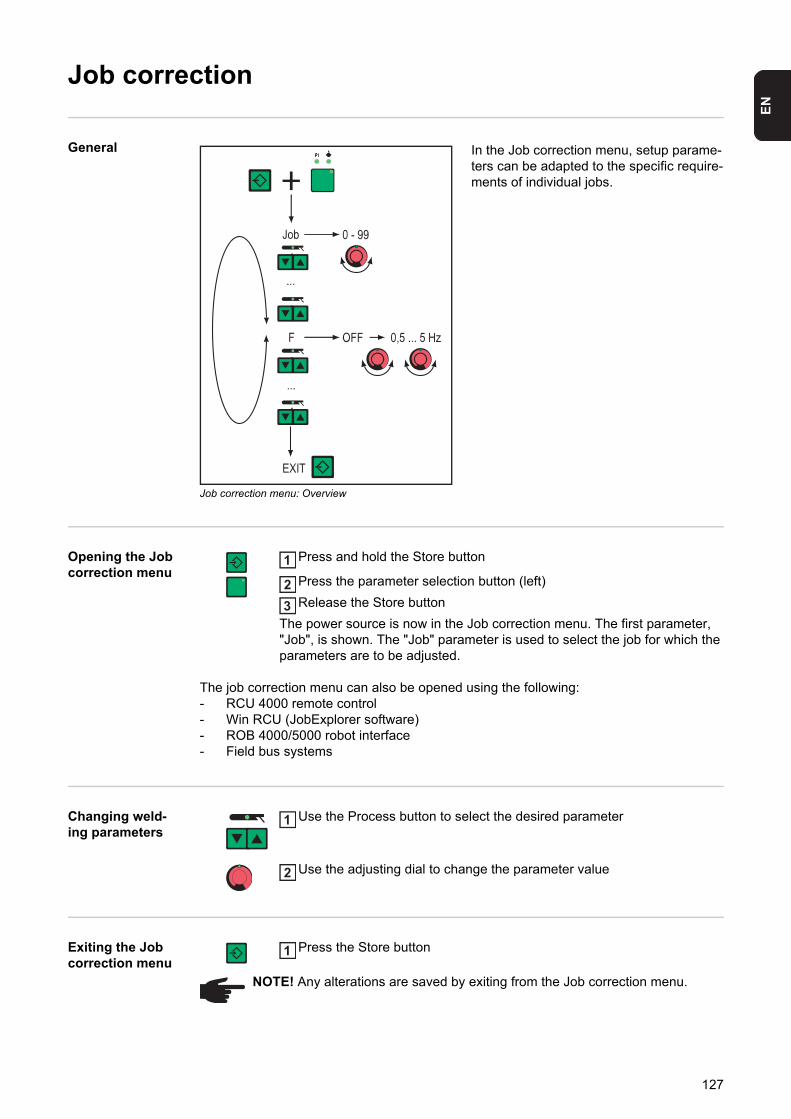
EN
Job correction
General
Job correction menu: Overview
In the Job correction menu, setup parame-ters can be adapted to the specific require-ments of individual jobs.
Opening the Job correction menu
Press and hold the Store button
Press the parameter selection button (left)
Release the Store button
The power source is now in the Job correction menu. The first parameter, "Job", is shown. The "Job" parameter is used to select the job for which the parameters are to be adjusted.
The job correction menu can also be opened using the following:- RCU 4000 remote control- Win RCU (JobExplorer software)- ROB 4000/5000 robot interface- Field bus systems
Changing weld-ing parameters
Use the Process button to select the desired parameter
Use the adjusting dial to change the parameter value
Exiting the Job correction menu
Press the Store button
1
23
1
2
NOTE! Any alterations are saved by exiting from the Job correction menu.
1
127
Parameters in the job correction menu
There are two types of parameter in the job correction menu:
permanently settable parameters:- cannot be altered apart from in the job correction menu.- can only be corrected in the job correction menu.
parameters that can be corrected at a later time:- with boundary values for which an adjusting range can be defined- within this adjusting range, these parameters can be corrected from the following con-
trol elements:- Control panel (Comfort, US, TIME 5000 Digital, CMT)- JobMaster welding torch- RCU 4000 remote control- Win RCU (JobExplorer software)
Permanently set-table parameters
"Minimum" and "maximum" are used for setting ranges that differ according to power source, wire-feed unit, welding program, etc.
JobJob whose parameters are to be adjusted
Unit -
Setting range 0 - 99 = numbers of the programmed jobsn = memory location vacant
Factory setting -
PPower correction - correction of the welding power as defined by the wire feed speed
Unit m/min ipm
Setting range e.g.: 5 - 22 e.g.: 0.2 - 866.14
The setting range depends upon which job has been selected.
Factory setting -
AL.1Arc length correction 1 - general arc length correction
Unit % (of welding voltage)
Setting range ± 30%
Factory setting -
NOTE! When the SynchroPulse option is enabled, AL.1 is the arc length correc-tion for the lower operating point of the pulsed welding power. The arc length cor-rection for the upper operating point is made using parameter AL.2.
dYndynamic - arc force dynamic correction for standard arcs or pulse correction for pulsed arcs.The function of the "dyn" parameter corresponds to the droplet detachment correction/arc force dynamic correction/arc force dynamic parameter on the control panel, described un-der "Welding".
Unit 1
Setting range ± 5
Factory setting -
GPrGas pre-flow time
128
EN
Unit s
Setting range 0 - 9.9
Factory setting 0.1
GPoGas post-flow time
Unit s
Setting range 0 - 9.9
Factory setting 0.5
FDcFeeder creep - wire feeder creep speed
Unit m/min ipm
Setting range AUT, OFF or 0.5 - max. AUT, OFF or 19.69 - max.
Additional possible setting with SFi option: SFi
Factory setting AUT AUT
NOTE! If Fdc is set to AUT, the value from the welding program database will be used. If Fdc values are set manually and these values are faster than the wire feed speed that was set for the welding operation then the feeder creep speed is equal to the wire feed speed set for the welding operation.
FdiFeeder inching
Unit m/min ipm
Setting range 1 - max. 39.37 - max.
Factory setting 10 393.7
bbcBurn-back time correction
Unit s
Setting range ± 0.20
Factory setting 0
I-SI (current) - Starting current
Unit % (of starting current)
Setting range 0 - 200
Factory setting 135
SLSlope
Unit s
Setting range 0.1 - 9.9
Factory setting 1.0
I-EI (current) - End - Final current
Unit % (of starting current)
Setting range 0 - 200
Factory setting 50
t-Stime - Starting current - Starting current duration
Unit s
Setting range OFF or 0.1 - 9.9
129
Parameters that can be corrected at a later time
Factory setting OFF
t-Etime - End current - Final current duration
Unit s
Setting range OFF or 0.1 - 9.9
Factory setting OFF
SPtSpot welding time
Unit s
Setting range 0.1 - 5.0
Factory setting 1.0
FFrequency - for SynchroPulse option
Unit Hz
Setting range OFF or 0.5 - 5
Factory setting OFF
dFddelta Feeder - Welding power offset for the SynchroPulse option (defined by the wire feed speed)
Unit m/min ipm
Setting range 0.0 - 2.0 0.0 - 78.74
Factory setting 2,0 78.74
AL.2Arc length correction 2 (for the upper operating point of the pulsed welding power with the SynchroPulse option)
Unit % (of welding voltage)
Setting range ± 30
Factory setting 0
NOTE! The arc length correction for the lower operating point is made using pa-rameter AL.1.
triTrigger - subsequent correction of the mode: 2-step, 4-step, special 2-step, special 4-step, spot welding
Unit -
Setting range 2-step, 4-step, special 4-step, spot welding
Factory setting 2-step
NOTE! During welding, the welding power (defined by the wire feed speed) or arc length can only be corrected as follows:- via the control panel (Comfort, US, TIME 5000 Digital, CMT)- via the JobMaster welding torch- via the RCU 4000 remote control- via Win RCU (JobExplorer software)- within the defined boundaries (listed below for the parameters PcH, PcL and
AL.c)
130
EN
As long as the power source is switched on, the corrected parameter values remain saved. After the power source has been switched on again, the parameters are reset to the per-manently settable values.
"Minimum" and "maximum" are used for setting ranges that differ according to power source, wire-feed unit, welding program, etc.
PcHPower correction High - Correction boundary (high) for the welding power
Unit % (of permanently settable parameter P - power correction)
Setting range 0 - 20
Factory setting 0
NOTE! The maximum amount by which parameter P can be increased is the val-ue set for PcL.
PcLPower correction Low - Correction boundary (low) for the welding power
Unit % (of permanently settable parameter P - power correction)
Setting range 0 - 20
Factory setting 0
NOTE! The maximum amount by which parameter P can be decreased is the val-ue set for PcL.
AL.cArc length correction (up or down)
Unit % (of permanently settable parameter AL.1)
Setting range 0 - 30
Factory setting 0
NOTE! The maximum amount by which parameter AL.1 can be increased or de-creased is the value specified for AL.c.
JSLJob Slope - defines the time between the job that is currently selected and the next job
Unit s
Setting range OFF or 0.1 - 9.9
Factory setting OFF
131
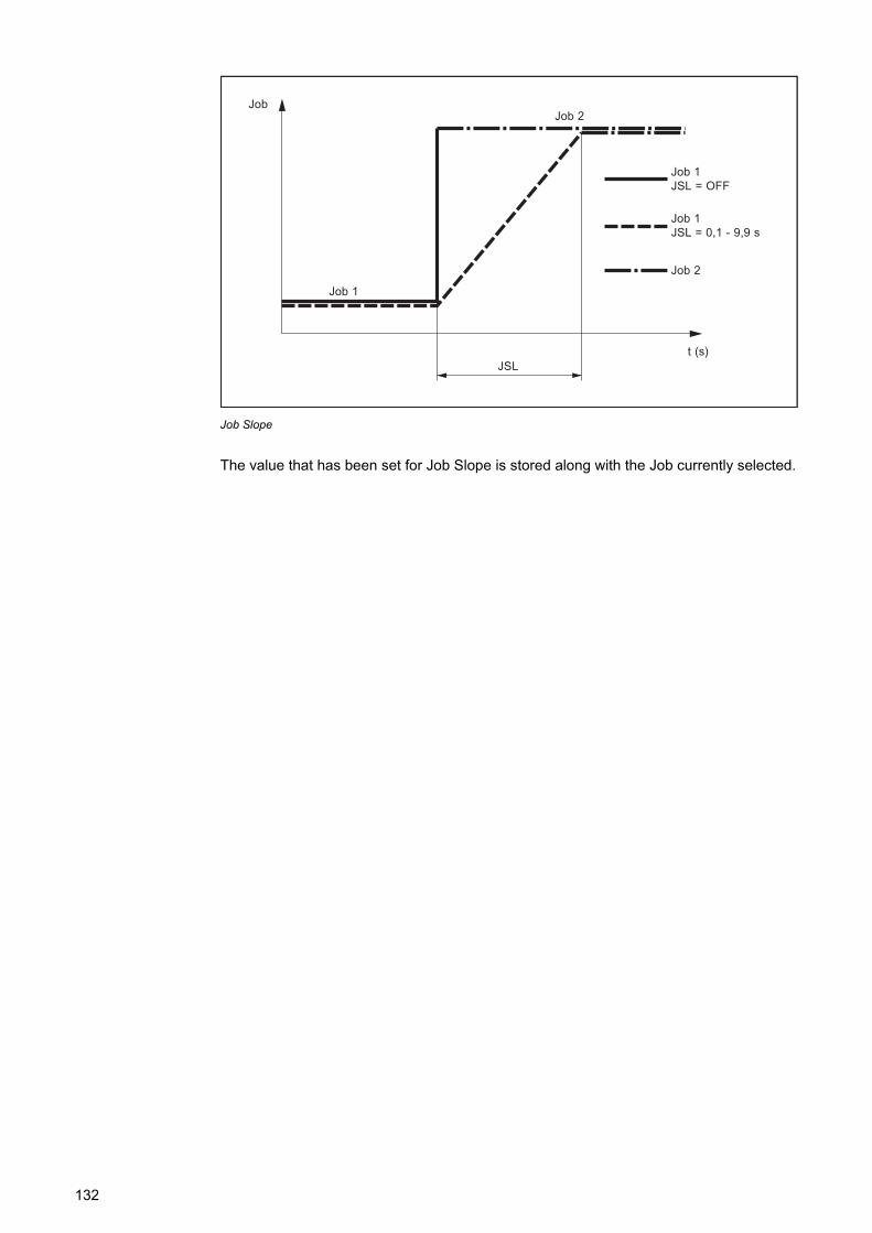
Job Slope
The value that has been set for Job Slope is stored along with the Job currently selected.
Job
t (s)
Job 1
Job 2
Job 1JSL = OFF
Job 1JSL = 0,1 - 9,9 s
JSL
Job 2
132
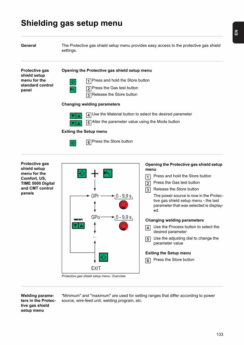
EN
Shielding gas setup menu
General The Protective gas shield setup menu provides easy access to the protective gas shield settings.
Protective gas shield setup menu for the standard control panel
Opening the Protective gas shield setup menu
Press and hold the Store button
Press the Gas test button
Release the Store button
Changing welding parameters
Use the Material button to select the desired parameter
Alter the parameter value using the Mode button
Exiting the Setup menu
Press the Store button
Protective gas shield setup menu for the Comfort, US, TIME 5000 Digital and CMT control panels
Protective gas shield setup menu: Overview
Opening the Protective gas shield setup menu
Press and hold the Store button
Press the Gas test button
Release the Store button
The power source is now in the Protec-tive gas shield setup menu - the last parameter that was selected is display-ed.
Changing welding parameters
Use the Process button to select the desired parameter
Use the adjusting dial to change the parameter value
Exiting the Setup menu
Press the Store button
Welding parame-ters in the Protec-tive gas shield setup menu
"Minimum" and "maximum" are used for setting ranges that differ according to power source, wire-feed unit, welding program, etc.
1
23
4
5
6
123
4
5
6
133
Purging of the shielding gas begins as soon as GPU is allocated a value.
For safety reasons, purging of the shielding gas cannot be restarted until a new GPU value is entered.
GPrGas pre-flow time
Unit s
Setting range 0 - 9.9
Factory setting 0.1
GPoGas post-flow time
Unit s
Setting range 0 - 9.9
Factory setting 0.5
GPUGas purger
Unit min
Setting range OFF or 0.1 - 10.0
Factory setting OFF
NOTE! Purging the shielding gas is necessary if condensation forms when the device is left unused in a cold environment for a prolonged period. Long hosepa-cks are most affected.
GASGasflow - set value for shielding gas flow (digital gas control option)
Unit l/min cfh
Setting range OFF or 0.5 - max. OFF or 10.71 - max.
Factory setting 15.0 32.14
NOTE! Please refer to the “Digital Gas Control” operating instructions for more detailed explanations of the “GAS” parameter.
134
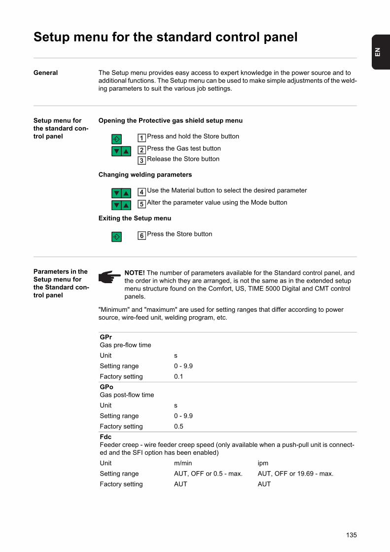
EN
Setup menu for the standard control panel
General The Setup menu provides easy access to expert knowledge in the power source and to additional functions. The Setup menu can be used to make simple adjustments of the weld-ing parameters to suit the various job settings.
Setup menu for the standard con-trol panel
Opening the Protective gas shield setup menu
Press and hold the Store button
Press the Gas test button
Release the Store button
Changing welding parameters
Use the Material button to select the desired parameter
Alter the parameter value using the Mode button
Exiting the Setup menu
Press the Store button
Parameters in the Setup menu for the Standard con-trol panel
"Minimum" and "maximum" are used for setting ranges that differ according to power source, wire-feed unit, welding program, etc.
1
23
4
5
6
NOTE! The number of parameters available for the Standard control panel, and the order in which they are arranged, is not the same as in the extended setup menu structure found on the Comfort, US, TIME 5000 Digital and CMT control panels.
GPrGas pre-flow time
Unit s
Setting range 0 - 9.9
Factory setting 0.1
GPoGas post-flow time
Unit s
Setting range 0 - 9.9
Factory setting 0.5
FdcFeeder creep - wire feeder creep speed (only available when a push-pull unit is connect-ed and the SFI option has been enabled)
Unit m/min ipm
Setting range AUT, OFF or 0.5 - max. AUT, OFF or 19.69 - max.
Factory setting AUT AUT
135
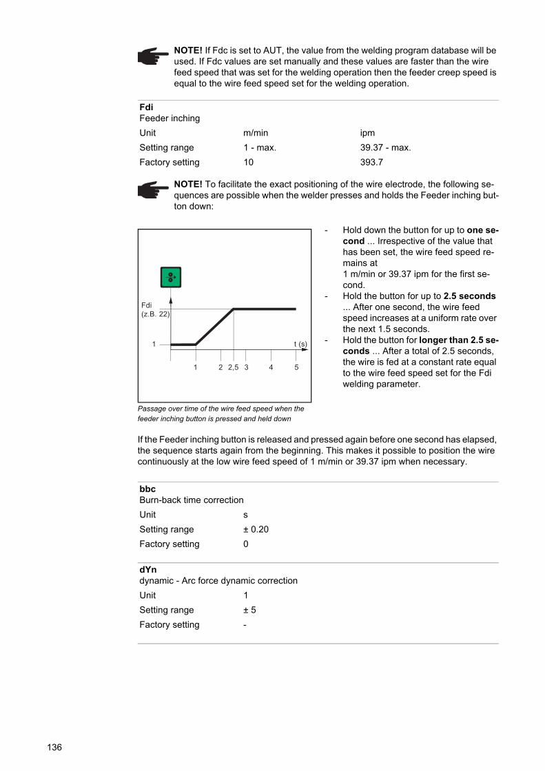
Passage over time of the wire feed speed when the feeder inching button is pressed and held down
- Hold down the button for up to one se-cond ... Irrespective of the value that has been set, the wire feed speed re-mains at1 m/min or 39.37 ipm for the first se-cond.
- Hold the button for up to 2.5 seconds ... After one second, the wire feed speed increases at a uniform rate over the next 1.5 seconds.
- Hold the button for longer than 2.5 se-conds ... After a total of 2.5 seconds, the wire is fed at a constant rate equal to the wire feed speed set for the Fdi welding parameter.
If the Feeder inching button is released and pressed again before one second has elapsed, the sequence starts again from the beginning. This makes it possible to position the wire continuously at the low wire feed speed of 1 m/min or 39.37 ipm when necessary.
NOTE! If Fdc is set to AUT, the value from the welding program database will be used. If Fdc values are set manually and these values are faster than the wire feed speed that was set for the welding operation then the feeder creep speed is equal to the wire feed speed set for the welding operation.
FdiFeeder inching
Unit m/min ipm
Setting range 1 - max. 39.37 - max.
Factory setting 10 393.7
NOTE! To facilitate the exact positioning of the wire electrode, the following se-quences are possible when the welder presses and holds the Feeder inching but-ton down:
t (s)
1 2 3 4 52,5
1
Fdi(z.B. 22)
bbcBurn-back time correction
Unit s
Setting range ± 0.20
Factory setting 0
dYndynamic - Arc force dynamic correction
Unit 1
Setting range ± 5
Factory setting -
136
EN
When the power source is reset, jobs are not deleted but are retained in the memory. The functions in the second level of the Setup menu (2nd) are also not deleted. Exception: Ig-nition time-out welding parameter (ito).
I-SI (current) - Starting current
Unit % (of starting current)
Setting range 0 - 200
Factory setting 135
SLSlope
Unit s
Setting range 0.1 - 9.9
Factory setting 1.0
I-EI (current) - End - Final current
Unit % (of starting current)
Setting range 0 - 200
Factory setting 50
FACReset power source to factory settingPress and hold down the Store button for 2 s to restore the factory settingswhen "PrG" appears on the digital display, the power source has been reset
NOTE! When the power source is reset, all the customised settings in the Setup menu are lost.
2ndSecond level of the Setup menu (see “Setup menu - level 2”)
t-Stime - Starting current - Starting current duration
Unit s
Setting range OFF or 0.1 - 9.9
Factory setting OFF
t-Etime - End current - Final current duration
Unit s
Setting range OFF or 0.1 - 9.9
Factory setting OFF
137
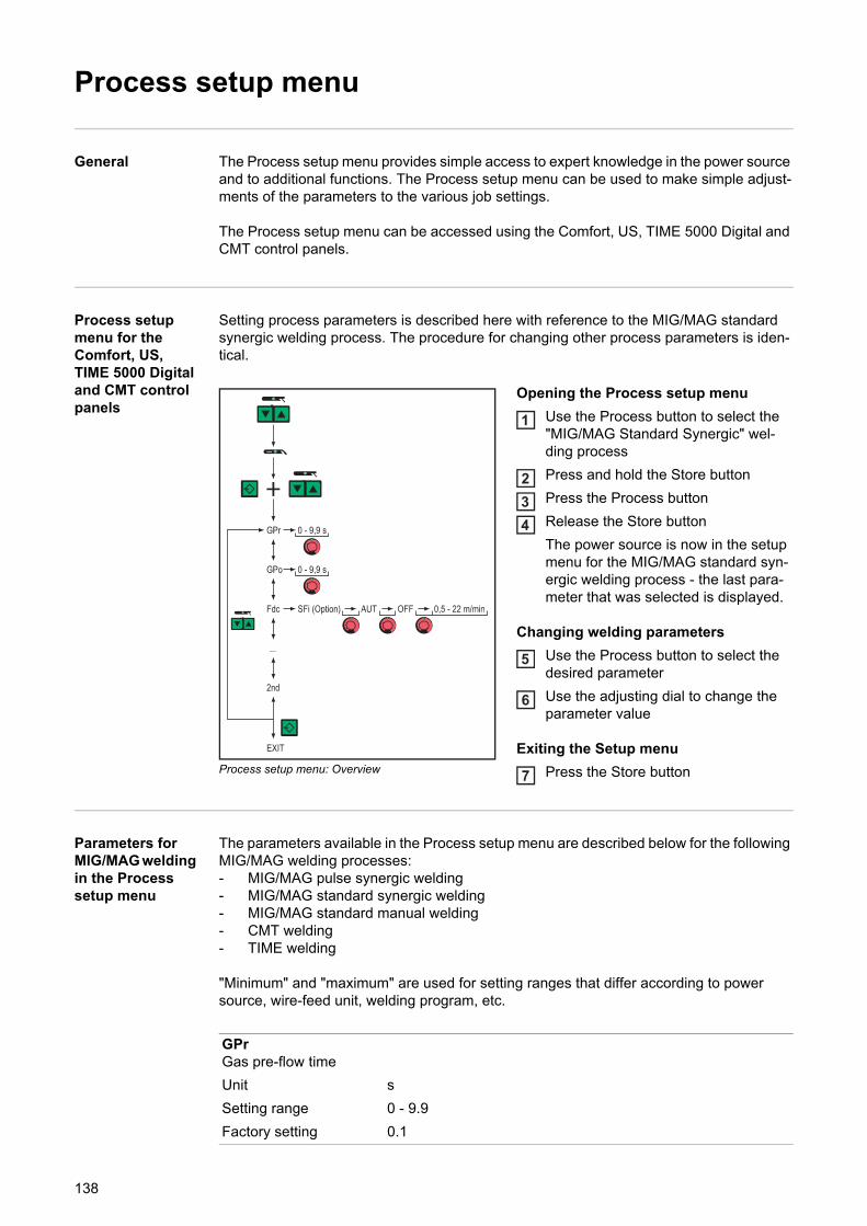
Process setup menu
General The Process setup menu provides simple access to expert knowledge in the power source and to additional functions. The Process setup menu can be used to make simple adjust-ments of the parameters to the various job settings.
The Process setup menu can be accessed using the Comfort, US, TIME 5000 Digital and CMT control panels.
Process setup menu for the Comfort, US, TIME 5000 Digital and CMT control panels
Setting process parameters is described here with reference to the MIG/MAG standard synergic welding process. The procedure for changing other process parameters is iden-tical.
Process setup menu: Overview
Opening the Process setup menu
Use the Process button to select the "MIG/MAG Standard Synergic" wel-ding process
Press and hold the Store button
Press the Process button
Release the Store button
The power source is now in the setup menu for the MIG/MAG standard syn-ergic welding process - the last para-meter that was selected is displayed.
Changing welding parameters
Use the Process button to select the desired parameter
Use the adjusting dial to change the parameter value
Exiting the Setup menu
Press the Store button
Parameters for MIG/MAG welding in the Process setup menu
The parameters available in the Process setup menu are described below for the following MIG/MAG welding processes:- MIG/MAG pulse synergic welding- MIG/MAG standard synergic welding- MIG/MAG standard manual welding- CMT welding- TIME welding
"Minimum" and "maximum" are used for setting ranges that differ according to power source, wire-feed unit, welding program, etc.
1
234
5
6
7
GPrGas pre-flow time
Unit s
Setting range 0 - 9.9
Factory setting 0.1
138
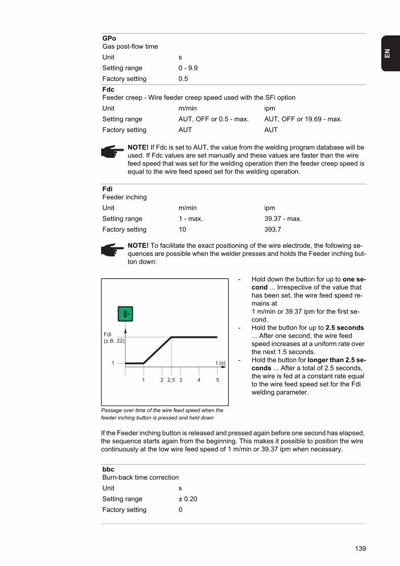
EN
Passage over time of the wire feed speed when the feeder inching button is pressed and held down
- Hold down the button for up to one se-cond ... Irrespective of the value that has been set, the wire feed speed re-mains at1 m/min or 39.37 ipm for the first se-cond.
- Hold the button for up to 2.5 seconds ... After one second, the wire feed speed increases at a uniform rate over the next 1.5 seconds.
- Hold the button for longer than 2.5 se-conds ... After a total of 2.5 seconds, the wire is fed at a constant rate equal to the wire feed speed set for the Fdi welding parameter.
If the Feeder inching button is released and pressed again before one second has elapsed, the sequence starts again from the beginning. This makes it possible to position the wire continuously at the low wire feed speed of 1 m/min or 39.37 ipm when necessary.
GPoGas post-flow time
Unit s
Setting range 0 - 9.9
Factory setting 0.5
FdcFeeder creep - Wire feeder creep speed used with the SFi option
Unit m/min ipm
Setting range AUT, OFF or 0.5 - max. AUT, OFF or 19.69 - max.
Factory setting AUT AUT
NOTE! If Fdc is set to AUT, the value from the welding program database will be used. If Fdc values are set manually and these values are faster than the wire feed speed that was set for the welding operation then the feeder creep speed is equal to the wire feed speed set for the welding operation.
FdiFeeder inching
Unit m/min ipm
Setting range 1 - max. 39.37 - max.
Factory setting 10 393.7
NOTE! To facilitate the exact positioning of the wire electrode, the following se-quences are possible when the welder presses and holds the Feeder inching but-ton down:
t (s)
1 2 3 4 52,5
1
Fdi(z.B. 22)
bbcBurn-back time correction
Unit s
Setting range ± 0.20
Factory setting 0
139
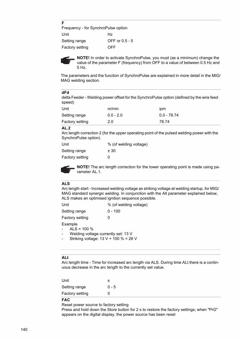
The parameters and the function of SynchroPulse are explained in more detail in the MIG/MAG welding section.
FFrequency - for SynchroPulse option
Unit Hz
Setting range OFF or 0.5 - 5
Factory setting OFF
NOTE! In order to activate SynchroPulse, you must (as a minimum) change the value of the parameter F (frequency) from OFF to a value of between 0.5 Hz and 5 Hz.
dFddelta Feeder - Welding power offset for the SynchroPulse option (defined by the wire feed speed)
Unit m/min ipm
Setting range 0.0 - 2.0 0.0 - 78.74
Factory setting 2.0 78.74
AL.2Arc length correction 2 (for the upper operating point of the pulsed welding power with the SynchroPulse option)
Unit % (of welding voltage)
Setting range ± 30
Factory setting 0
NOTE! The arc length correction for the lower operating point is made using pa-rameter AL.1.
ALSArc length start - Increased welding voltage as striking voltage at welding startup, for MIG/MAG standard synergic welding. In conjunction with the Alt parameter explained below, ALS makes an optimised ignition sequence possible.
Unit % (of welding voltage)
Setting range 0 - 100
Factory setting 0
Example- ALS = 100 %- Welding voltage currently set: 13 V- Striking voltage: 13 V + 100 % = 26 V
ALtArc length time - Time for increased arc length via ALS. During time ALt there is a contin-uous decrease in the arc length to the currently set value.
Unit s
Setting range 0 - 5
Factory setting 0
FACReset power source to factory settingPress and hold down the Store button for 2 s to restore the factory settings; when "PrG" appears on the digital display, the power source has been reset
140
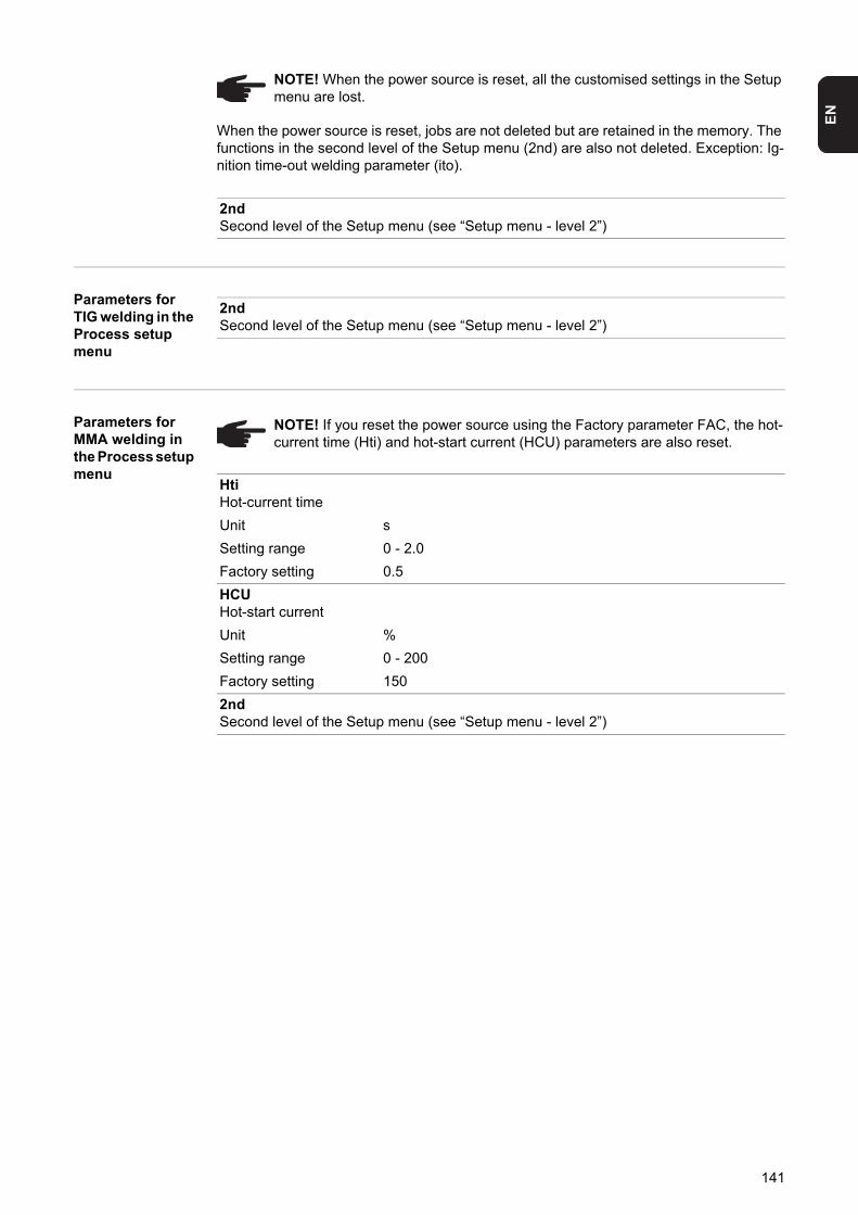
EN
When the power source is reset, jobs are not deleted but are retained in the memory. The functions in the second level of the Setup menu (2nd) are also not deleted. Exception: Ig-nition time-out welding parameter (ito).
Parameters for TIG welding in the Process setup menu
Parameters for MMA welding in the Process setup menu
NOTE! When the power source is reset, all the customised settings in the Setup menu are lost.
2ndSecond level of the Setup menu (see “Setup menu - level 2”)
2ndSecond level of the Setup menu (see “Setup menu - level 2”)
NOTE! If you reset the power source using the Factory parameter FAC, the hot-current time (Hti) and hot-start current (HCU) parameters are also reset.
HtiHot-current time
Unit s
Setting range 0 - 2.0
Factory setting 0.5
HCUHot-start current
Unit %
Setting range 0 - 200
Factory setting 150
2ndSecond level of the Setup menu (see “Setup menu - level 2”)
141
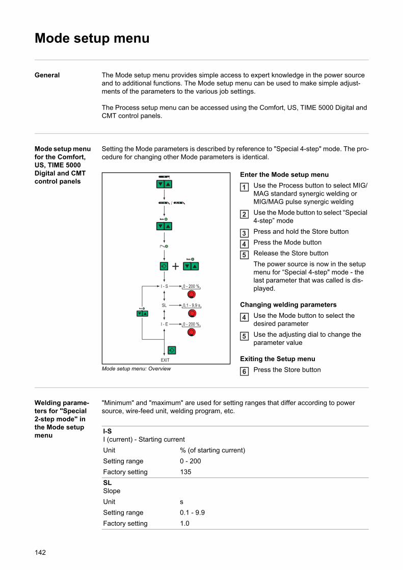
Mode setup menu
General The Mode setup menu provides simple access to expert knowledge in the power source and to additional functions. The Mode setup menu can be used to make simple adjust-ments of the parameters to the various job settings.
The Process setup menu can be accessed using the Comfort, US, TIME 5000 Digital and CMT control panels.
Mode setup menu for the Comfort, US, TIME 5000 Digital and CMT control panels
Setting the Mode parameters is described by reference to "Special 4-step" mode. The pro-cedure for changing other Mode parameters is identical.
Mode setup menu: Overview
Enter the Mode setup menu
Use the Process button to select MIG/MAG standard synergic welding or MIG/MAG pulse synergic welding
Use the Mode button to select “Special 4-step” mode
Press and hold the Store button
Press the Mode button
Release the Store button
The power source is now in the setup menu for “Special 4-step" mode - the last parameter that was called is dis-played.
Changing welding parameters
Use the Mode button to select the desired parameter
Use the adjusting dial to change the parameter value
Exiting the Setup menu
Press the Store button
Welding parame-ters for "Special 2-step mode" in the Mode setup menu
"Minimum" and "maximum" are used for setting ranges that differ according to power source, wire-feed unit, welding program, etc.
1
2
345
4
5
6
I-SI (current) - Starting current
Unit % (of starting current)
Setting range 0 - 200
Factory setting 135
SLSlope
Unit s
Setting range 0.1 - 9.9
Factory setting 1.0
142
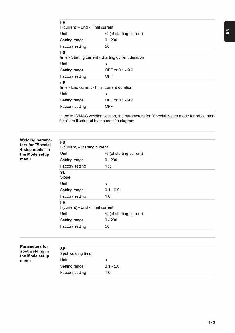
EN
In the MIG/MAG welding section, the parameters for "Special 2-step mode for robot inter-face" are illustrated by means of a diagram.
Welding parame-ters for "Special 4-step mode" in the Mode setup menu
Parameters for spot welding in the Mode setup menu
I-EI (current) - End - Final current
Unit % (of starting current)
Setting range 0 - 200
Factory setting 50
t-Stime - Starting current - Starting current duration
Unit s
Setting range OFF or 0.1 - 9.9
Factory setting OFF
t-Etime - End current - Final current duration
Unit s
Setting range OFF or 0.1 - 9.9
Factory setting OFF
I-SI (current) - Starting current
Unit % (of starting current)
Setting range 0 - 200
Factory setting 135
SLSlope
Unit s
Setting range 0.1 - 9.9
Factory setting 1.0
I-EI (current) - End - Final current
Unit % (of starting current)
Setting range 0 - 200
Factory setting 50
SPtSpot welding time
Unit s
Setting range 0.1 - 5.0
Factory setting 1.0
143
Setup menu - Level 2
General The following functions are located in a second menu level:
Setup menulevel 2 for the Standard control panel
Changing to the second menu level (2nd)
Access the Setup menu for the Standard control panel
Select "2nd" welding parameter
Press and hold the Store button
Press the Mode button
Release the Store button
The power source is now in the second menu level (2nd) of the Setup menu. The func-tion “PPU” (push-pull unit) is displayed.
Selecting the function
Use the Material button to select the desired function
Make the settings for this function with the Mode button
Exiting from the second menu level (2nd)
Press the Store button
The power source is now in the Setup menu for the Standard control panel.
To exit from the Setup menu for the Standard control panelpress the Store button again
- PPU (push-pull unit)- C-C (cooling unit cut-out)- Stc (wire-stick - only where there is a
robot interface)- Ito (ignition time-out)- Arc (arc break watchdog)- S4t (gun trigger option)- Gun (option for changing between
modes with the JobMaster torch)
- r (welding circuit resistance measure-ment)
- L (welding circuit inductivity display)- Eln (characteristic selection - not on
Standard control panel)- ASt (Anti-stick - not on Standard con-
trol panel)- COr (gas correction for digital gas con-
trol option)
12
3
45
6
7
8
9
144
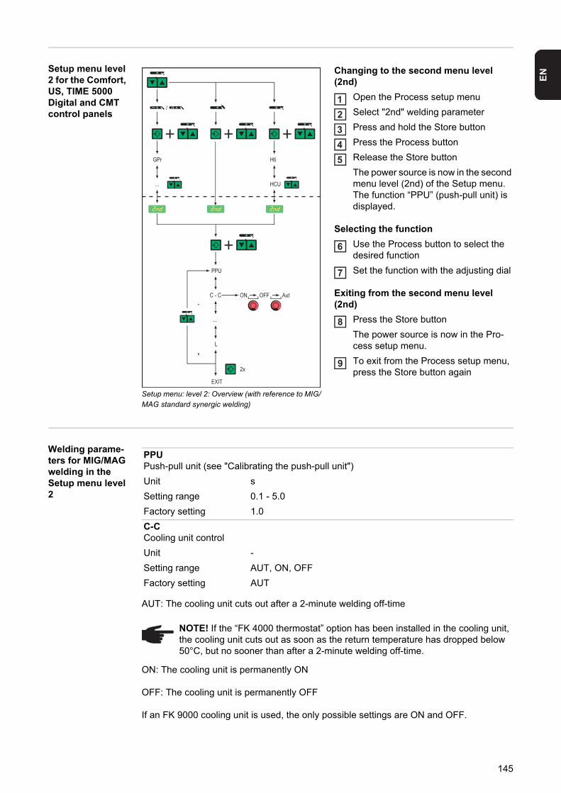
EN
Setup menu level2 for the Comfort, US, TIME 5000 Digital and CMT control panels
Setup menu: level 2: Overview (with reference to MIG/MAG standard synergic welding)
Changing to the second menu level (2nd)
Open the Process setup menu
Select "2nd" welding parameter
Press and hold the Store button
Press the Process button
Release the Store button
The power source is now in the second menu level (2nd) of the Setup menu. The function “PPU” (push-pull unit) is displayed.
Selecting the function
Use the Process button to select the desired function
Set the function with the adjusting dial
Exiting from the second menu level (2nd)
Press the Store button
The power source is now in the Pro-cess setup menu.
To exit from the Process setup menu, press the Store button again
Welding parame-ters for MIG/MAG welding in the Setup menu level 2
AUT: The cooling unit cuts out after a 2-minute welding off-time
ON: The cooling unit is permanently ON
OFF: The cooling unit is permanently OFF
If an FK 9000 cooling unit is used, the only possible settings are ON and OFF.
12345
6
7
8
9
PPUPush-pull unit (see "Calibrating the push-pull unit")
Unit s
Setting range 0.1 - 5.0
Factory setting 1.0
C-CCooling unit control
Unit -
Setting range AUT, ON, OFF
Factory setting AUT
NOTE! If the “FK 4000 thermostat” option has been installed in the cooling unit, the cooling unit cuts out as soon as the return temperature has dropped below 50°C, but no sooner than after a 2-minute welding off-time.
145
Example:- MIG/MAG welding process ... e.g. use of a water-cooled welding torch: C-C = AUT- TIG welding process ... e.g. use of a gas-cooled welding torch: C-C = OFF
NOTE! Parameter C-C can be set differently for MIG/MAG welding and TIG weld-ing.
C-tCooling time - Time from when the rate-of-flow watchdog is triggered until the "no | H2O" service code is output. For example, if there are air bubbles in the cooling system, the cooling unit will not cut out until the end of this pre-set time.
Unit s
Setting range 5 - 25
Factory setting 10
NOTE! Every time the power source is switched on, the cooling unit will do a 180-second test run.
StcWire-stick control
Unit -
Setting range OFF, ON
Factory setting OFF
The parameters for the wire-stick function (Stc) are available when a robot interface or field bus coupler for robot control is connected to the LocalNet.
The wire-stick control function (Stc) is described in the "Robot welding" section.
ItoIgnition time-out - Length of wire that is fed before the safety cut-out is triggered
Unit mm in.
Setting range OFF or 5 - 100 OFF or 0.20 - 3.94
Factory setting OFF
NOTE! The "Ignition time-out" function (ito) is a safety function. The length of wire that is fed before the safety cut-out trips may differ from the pre-set wire length, particularly when the wire is being fed at fast wire feed speeds.
The “Ignition time-out” function (ito) is explained in the “Special functions and options” section.
ArcArc - Arc break watchdog
Unit s
Setting range OFF (arc break watchdog is deactivated);0.01 - 2 (arc break watchdog is activated)
Factory setting OFF
The “Arc break watchdog” function (Arc) is explained in the “Special functions and op-tions” section.
FCOFeeder control - Wire-feed unit cut-out (wire-end sensor option)
Unit -
Setting range OFF / ON / noE
Factory setting OFF
146
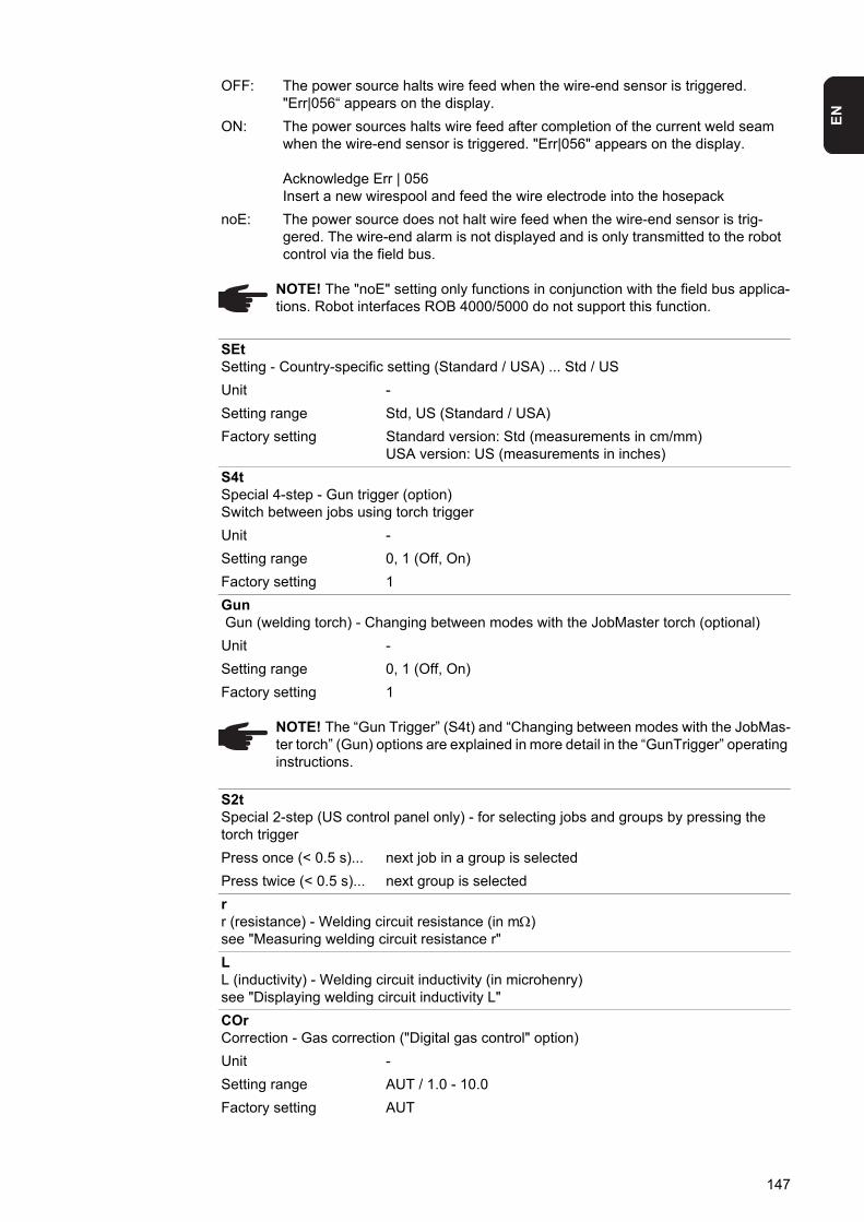
EN
OFF: The power source halts wire feed when the wire-end sensor is triggered. "Err|056“ appears on the display.
ON: The power sources halts wire feed after completion of the current weld seam when the wire-end sensor is triggered. "Err|056" appears on the display.
Acknowledge Err | 056Insert a new wirespool and feed the wire electrode into the hosepack
noE: The power source does not halt wire feed when the wire-end sensor is trig-gered. The wire-end alarm is not displayed and is only transmitted to the robot control via the field bus.
NOTE! The "noE" setting only functions in conjunction with the field bus applica-tions. Robot interfaces ROB 4000/5000 do not support this function.
SEtSetting - Country-specific setting (Standard / USA) ... Std / US
Unit -
Setting range Std, US (Standard / USA)
Factory setting Standard version: Std (measurements in cm/mm)USA version: US (measurements in inches)
S4tSpecial 4-step - Gun trigger (option)Switch between jobs using torch trigger
Unit -
Setting range 0, 1 (Off, On)
Factory setting 1
Gun Gun (welding torch) - Changing between modes with the JobMaster torch (optional)
Unit -
Setting range 0, 1 (Off, On)
Factory setting 1
NOTE! The “Gun Trigger” (S4t) and “Changing between modes with the JobMas-ter torch” (Gun) options are explained in more detail in the “GunTrigger” operating instructions.
S2tSpecial 2-step (US control panel only) - for selecting jobs and groups by pressing the torch trigger
Press once (< 0.5 s)... next job in a group is selected
Press twice (< 0.5 s)... next group is selected
rr (resistance) - Welding circuit resistance (in m)see "Measuring welding circuit resistance r"
LL (inductivity) - Welding circuit inductivity (in microhenry)see "Displaying welding circuit inductivity L"
COrCorrection - Gas correction ("Digital gas control" option)
Unit -
Setting range AUT / 1.0 - 10.0
Factory setting AUT
147
Parameters for operating power sources in paral-lel in the Setup menu level 2
Parameters for TimeTwin Digital in the Setup menu level 2
The T-C parameter is only available when two power sources are connected via an LHSB (LocalNet High-Speed Bus) and the “TimeTwin Digital” option has been enabled.
Parameters for TIG welding in the Setup menu level 2
AUT: The cooling unit cuts out after a 2-minute welding off-time
ON: The cooling unit is permanently ON
OFF: The cooling unit is permanently OFF
If an FK 9000 cooling unit is used, the only possible settings are ON and OFF.
NOTE! Please refer to "Digital Gas Control" operating instructions for more de-tailed explanations of the "COr" parameter.
P-CPower Control - for defining the Master or Slave power sources when two power sources are operated in parallel
Unit -
Setting range On (Master power source), OFF (Slave power source)
Factory setting OFF
NOTE! The P-C parameter is only available when two power sources are con-nected via an LHSB (LocalNet High-Speed Bus).
T-CTwin Control - for defining the leading or trailing power sources in the TimeTwin Digital process
Unit -
Setting range On (Leading power source), OFF (Trailing power source)
Factory setting -
NOTE! When a robot interface is connected to the power source, the T-C param-eter can only be adjusted via the robot interface.
C-CCooling unit control
Unit -
Setting range AUT, ON, OFF
Factory setting AUT
NOTE! If the “FK 4000 thermostat” option has been installed in the cooling unit, the cooling unit cuts out as soon as the return temperature has dropped below 50°C, but no sooner than after a 2-minute welding off-time.
NOTE! Parameter C-C can be set differently for MIG/MAG welding and TIG weld-ing.
148
EN
Example:- MIG/MAG welding process ... e.g. use of a water-cooled welding torch: C-C = AUT- TIG welding process ... e.g. use of a gas-cooled welding torch: C-C = OFF
Depending on the value of the CSS parameter, it may be necessary to lengthen the arc to trigger the TIG comfort stop function:- when CSS = 0.5 - 2.0 ......... small increase in the size of the arc- when CSS = 2.0 - 3.5 ......... medium increase in the size of the arc- when CSS = 3.5 - 5.0 ......... large increase in the size of the arc
Parameters for rod electrode (MMA) welding in the Setup menu level 2
CSSComfort stop sensitivity - Sensitivity of the response characteristic of the TIG comfort stop function
Unit -
Setting range 0.5 - 5.0 or OFF
Factory setting OFF
NOTE! A standard value setting of 2.0 is recommended for the CSS parameter. However, if the welding process is frequently stopped unintentionally, increase the value for the CSS parameter.
rr (resistance) - Welding circuit resistance (in m)see "Measuring welding circuit resistance r"
LL (inductivity) - Welding circuit inductivity (in microhenry)see "Displaying welding circuit inductivity L"
COrCorrection - Gas correction ("Digital gas control" option)
Unit -
Setting range AUT / 1.0 - 10.0
Factory setting AUT
NOTE! Please refer to "Digital Gas Control" operating instructions for more de-tailed explanations of the "COr" parameter.
ElnElectrode line - characteristic selection
Unit 1
Setting range CON or 0.1 - 20 or P
Factory setting CON
149
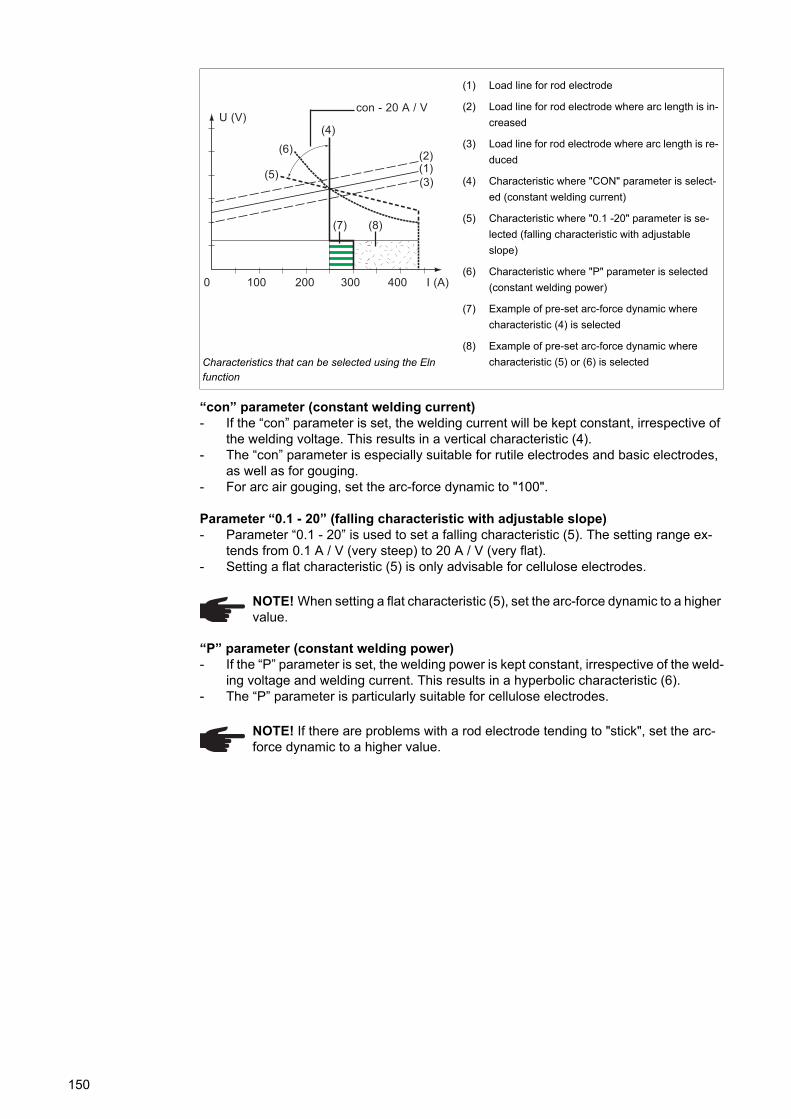
“con” parameter (constant welding current)- If the “con” parameter is set, the welding current will be kept constant, irrespective of
the welding voltage. This results in a vertical characteristic (4).- The “con” parameter is especially suitable for rutile electrodes and basic electrodes,
as well as for gouging.- For arc air gouging, set the arc-force dynamic to "100".
Parameter “0.1 - 20” (falling characteristic with adjustable slope)- Parameter “0.1 - 20” is used to set a falling characteristic (5). The setting range ex-
tends from 0.1 A / V (very steep) to 20 A / V (very flat).- Setting a flat characteristic (5) is only advisable for cellulose electrodes.
“P” parameter (constant welding power)- If the “P” parameter is set, the welding power is kept constant, irrespective of the weld-
ing voltage and welding current. This results in a hyperbolic characteristic (6).- The “P” parameter is particularly suitable for cellulose electrodes.
Characteristics that can be selected using the Eln function
(1) Load line for rod electrode
(2) Load line for rod electrode where arc length is in-
creased
(3) Load line for rod electrode where arc length is re-
duced
(4) Characteristic where "CON" parameter is select-
ed (constant welding current)
(5) Characteristic where "0.1 -20" parameter is se-
lected (falling characteristic with adjustable
slope)
(6) Characteristic where "P" parameter is selected
(constant welding power)
(7) Example of pre-set arc-force dynamic where
characteristic (4) is selected
(8) Example of pre-set arc-force dynamic where
characteristic (5) or (6) is selected
NOTE! When setting a flat characteristic (5), set the arc-force dynamic to a higher value.
NOTE! If there are problems with a rod electrode tending to "stick", set the arc-force dynamic to a higher value.
0040 200100 300 I (A)
U (V)con - 20 A / V
(4)
(5)
(6)
(7) (8)
(1)(2)
(3)
150
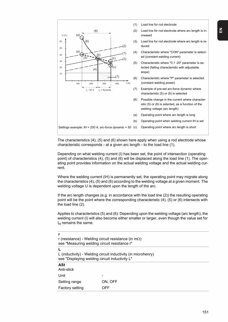
EN
The characteristics (4), (5) and (6) shown here apply when using a rod electrode whose characteristic corresponds - at a given arc length - to the load line (1).
Depending on what welding current (I) has been set, the point of intersection (operating point) of characteristics (4), (5) and (6) will be displaced along the load line (1). The oper-ating point provides information on the actual welding voltage and the actual welding cur-rent.
Where the welding current (IH) is permanently set, the operating point may migrate along the characteristics (4), (5) and (6) according to the welding voltage at a given moment. The welding voltage U is dependent upon the length of the arc.
If the arc length changes (e.g. in accordance with the load line (2)) the resulting operating point will be the point where the corresponding characteristic (4), (5) or (6) intersects with the load line (2).
Applies to characteristics (5) and (6): Depending upon the welding voltage (arc length), the welding current (I) will also become either smaller or larger, even though the value set for IH remains the same.
Settings example: IH = 250 A, arc-force dynamic = 50
(1) Load line for rod electrode
(2) Load line for rod electrode where arc length is in-
creased
(3) Load line for rod electrode where arc length is re-
duced
(4) Characteristic where "CON" parameter is select-
ed (constant welding current)
(5) Characteristic where "0.1 -20" parameter is se-
lected (falling characteristic with adjustable
slope)
(6) Characteristic where "P" parameter is selected
(constant welding power)
(7) Example of pre-set arc-force dynamic where
characteristic (5) or (6) is selected
(8) Possible change in the current where character-
istic (5) or (6) is selected, as a function of the
welding voltage (arc length)
(a) Operating point where arc length is long
(b) Operating point when welding current IH is set
(c) Operating point where arc length is short
rr (resistance) - Welding circuit resistance (in m)see "Measuring welding circuit resistance r"
LL (inductivity) - Welding circuit inductivity (in microhenry)see "Displaying welding circuit inductivity L"
AStAnti-stick
Unit -
Setting range ON, OFF
Factory setting OFF
10
20
30
40
50
60
U (V)
004003001 200 I (A)
IH + DynamikIH - 50 %
(8)
(2)
(1)
(3)
(7)
(c)
(c)(b)
(a)
(a)
(6)
(5)
(4)
151
Notes on the use of the FAC param-eter
The following parameters in Setup menu level 2 are not reset to the factory setting when the FAC parameter is used:- PPU- C-C- Stc- Arc- S4t- Gun
UcoU (Voltage) cut-off - Welding voltage limitation:
Unit V
Setting range OFF or 5 - 95
Factory setting OFF
NOTE! The arc length depends on the welding voltage. To end the welding proc-ess, it is usually necessary to significantly lift the rod electrode away from the workpiece. With the “Uco” parameter, the welding voltage can be limited to a val-ue that makes it possible to end the welding operation simply by slightly lifting the rod electrode.
If the welding process is stopped unintentionally during the welding, increase the value for the Uco parameter.
152
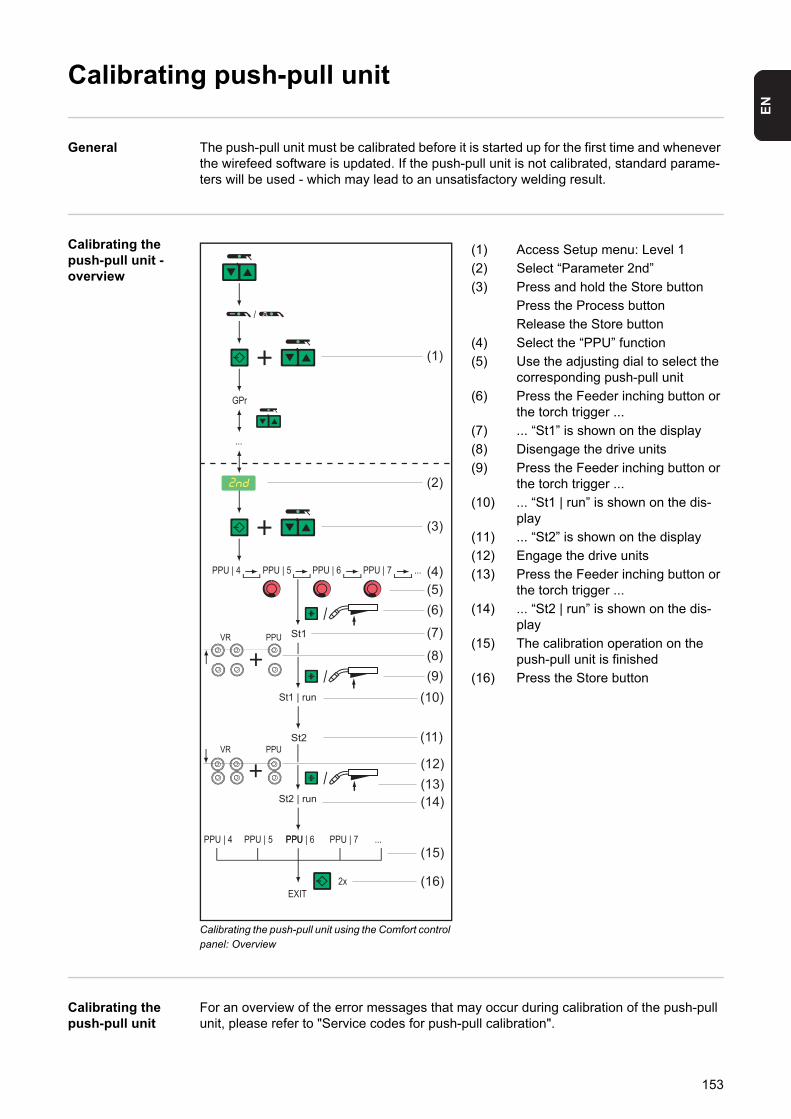
EN
Calibrating push-pull unit
General The push-pull unit must be calibrated before it is started up for the first time and whenever the wirefeed software is updated. If the push-pull unit is not calibrated, standard parame-ters will be used - which may lead to an unsatisfactory welding result.
Calibrating the push-pull unit - overview
Calibrating the push-pull unit using the Comfort control panel: Overview
(1) Access Setup menu: Level 1
(2) Select “Parameter 2nd”
(3) Press and hold the Store button
Press the Process button
Release the Store button
(4) Select the “PPU” function
(5) Use the adjusting dial to select the corresponding push-pull unit
(6) Press the Feeder inching button or the torch trigger ...
(7) ... “St1” is shown on the display
(8) Disengage the drive units
(9) Press the Feeder inching button or the torch trigger ...
(10) ... “St1 | run” is shown on the dis-play
(11) ... “St2” is shown on the display
(12) Engage the drive units
(13) Press the Feeder inching button or the torch trigger ...
(14) ... “St2 | run” is shown on the dis-play
(15) The calibration operation on the push-pull unit is finished
(16) Press the Store button
Calibrating the push-pull unit
For an overview of the error messages that may occur during calibration of the push-pull unit, please refer to "Service codes for push-pull calibration".
(1)
(2)
(3)
(4)(5)(6)
(9)
(7)
(10)
(11)
(8)
(13)(14)
(16)
(15)
(12)
153
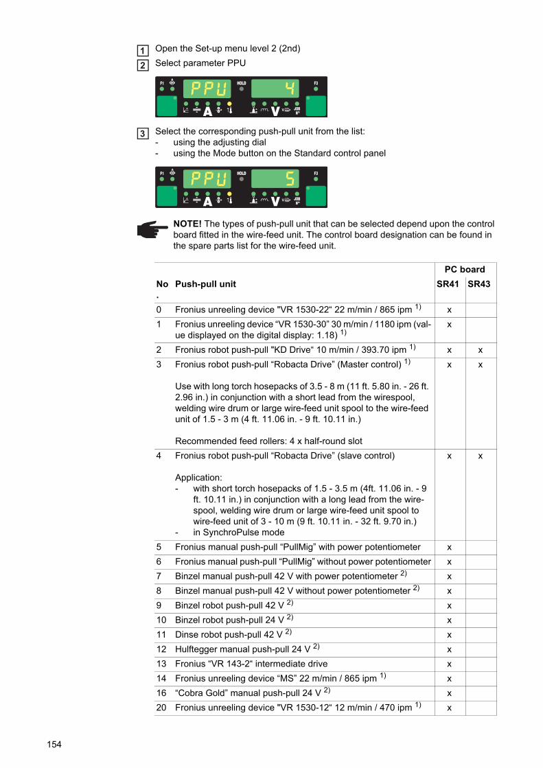
Open the Set-up menu level 2 (2nd)
Select parameter PPU
Select the corresponding push-pull unit from the list:- using the adjusting dial- using the Mode button on the Standard control panel
12
3
NOTE! The types of push-pull unit that can be selected depend upon the control board fitted in the wire-feed unit. The control board designation can be found in the spare parts list for the wire-feed unit.
PC board
No.
Push-pull unit SR41 SR43
0 Fronius unreeling device "VR 1530-22“ 22 m/min / 865 ipm 1) x
1 Fronius unreeling device “VR 1530-30” 30 m/min / 1180 ipm (val-ue displayed on the digital display: 1.18) 1)
x
2 Fronius robot push-pull "KD Drive“ 10 m/min / 393.70 ipm 1) x x
3 Fronius robot push-pull “Robacta Drive” (Master control) 1)
Use with long torch hosepacks of 3.5 - 8 m (11 ft. 5.80 in. - 26 ft. 2.96 in.) in conjunction with a short lead from the wirespool, welding wire drum or large wire-feed unit spool to the wire-feed unit of 1.5 - 3 m (4 ft. 11.06 in. - 9 ft. 10.11 in.)
Recommended feed rollers: 4 x half-round slot
x x
4 Fronius robot push-pull “Robacta Drive” (slave control)
Application:- with short torch hosepacks of 1.5 - 3.5 m (4ft. 11.06 in. - 9
ft. 10.11 in.) in conjunction with a long lead from the wire-spool, welding wire drum or large wire-feed unit spool to wire-feed unit of 3 - 10 m (9 ft. 10.11 in. - 32 ft. 9.70 in.)
- in SynchroPulse mode
x x
5 Fronius manual push-pull “PullMig” with power potentiometer x
6 Fronius manual push-pull “PullMig” without power potentiometer x
7 Binzel manual push-pull 42 V with power potentiometer 2) x
8 Binzel manual push-pull 42 V without power potentiometer 2) x
9 Binzel robot push-pull 42 V 2) x
10 Binzel robot push-pull 24 V 2) x
11 Dinse robot push-pull 42 V 2) x
12 Hulftegger manual push-pull 24 V 2) x
13 Fronius “VR 143-2“ intermediate drive x
14 Fronius unreeling device “MS” 22 m/min / 865 ipm 1) x
16 “Cobra Gold” manual push-pull 24 V 2) x
20 Fronius unreeling device "VR 1530-12“ 12 m/min / 470 ipm 1) x
154
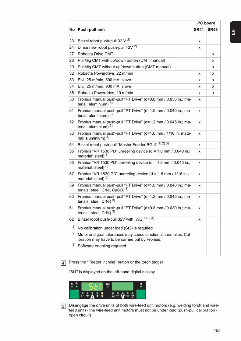
EN
Press the “Feeder inching” button or the torch trigger
"St1" is displayed on the left-hand digital display
Disengage the drive units of both wire-feed unit motors (e.g. welding torch and wire-feed unit) - the wire-feed unit motors must not be under load (push-pull calibration - open circuit)
23 Binzel robot push-pull 32 V 2) x
24 Dinse new robot push-pull 42V 2) x
27 Robacta Drive CMT x
28 PullMig CMT with up/down button (CMT manual) x
29 PullMig CMT without up/down button (CMT manual) x
32 Robacta Powerdrive, 22 m/min x x
33 Elvi, 25 m/min, 500 mA, slave x x
34 Elvi, 25 m/min, 900 mA, slave x x
35 Robacta Powerdrive, 10 m/min x x
50 Fronius manual push-pull “PT Drive” (d=0.8 mm / 0.030 in.; ma-terial: aluminium) 3)
x
51 Fronius manual push-pull “PT Drive” (d=1.0 mm / 0.040 in.; ma-terial: aluminium) 3)
x
52 Fronius manual push-pull “PT Drive” (d=1.2 mm / 0.045 in.; ma-terial: aluminium) 3)
x
53 Fronius manual push-pull “PT Drive” (d=1.6 mm / 1/16 in; mate-rial: aluminium) 3)
x
54 Binzel robot push-pull “Master Feeder BG II” 1) 2) 3) x
55 Fronius “VR 1530 PD” unreeling device (d = 1.0 mm / 0.040 in.; material: steel) 3)
x
56 Fronius “VR 1530 PD” unreeling device (d = 1.2 mm / 0.045 in.; material: steel) 3)
x
57 Fronius “VR 1530 PD” unreeling device (d = 1.6 mm / 1/16 in.; material: steel) 3)
x
59 Fronius manual push-pull “PT Drive” (d=1.0 mm / 0.040 in.; ma-terials: steel, CrNi, CuSi3) 3)
x
60 Fronius manual push-pull “PT Drive” (d=1.2 mm / 0.045 in.; ma-terials: steel, CrNi) 3)
x
61 Fronius manual push-pull “PT Drive” (d=0.8 mm / 0.030 in.; ma-terials: steel, CrNi) 3)
x
62 Binzel robot push-pull 32V with IWG 1) 2) 3) x
1) No calibration under load (St2) is required2) Motor and gear tolerances may cause functional anomalies. Cal-
ibration may have to be carried out by Fronius.3) Software enabling required
PC board
No.
Push-pull unit SR41 SR43
4
5
155
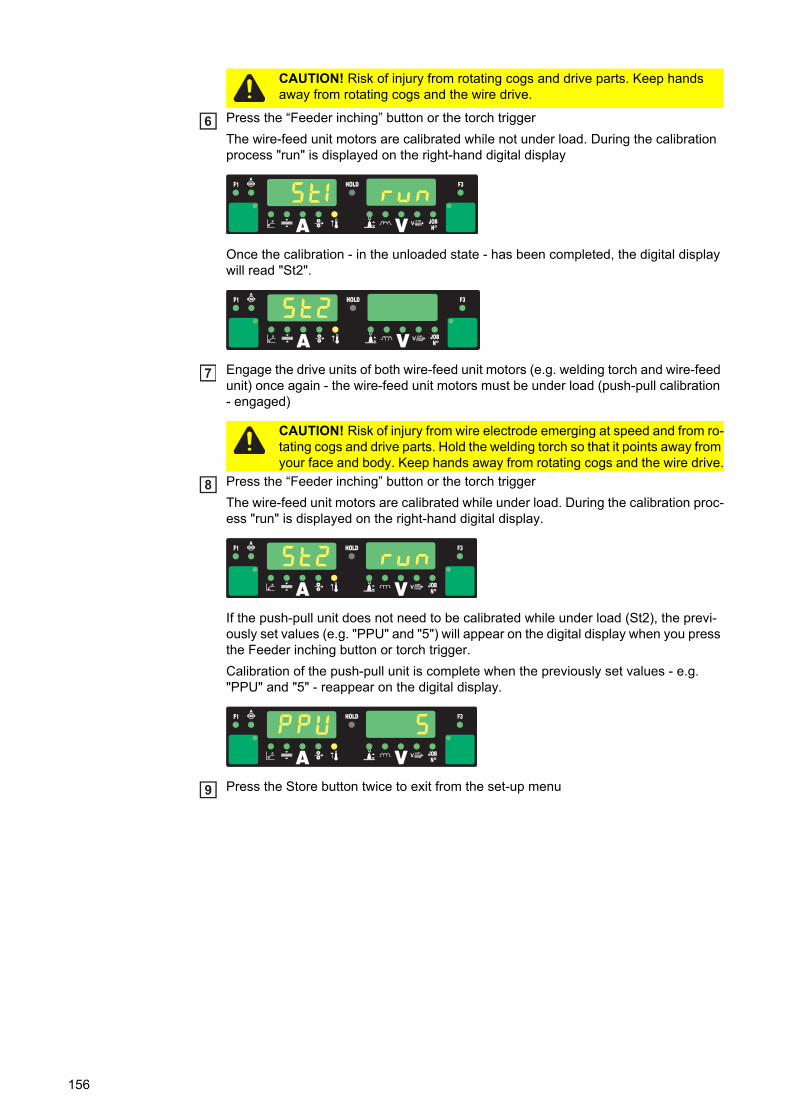
Press the “Feeder inching” button or the torch trigger
The wire-feed unit motors are calibrated while not under load. During the calibration process "run" is displayed on the right-hand digital display
Once the calibration - in the unloaded state - has been completed, the digital display will read "St2".
Engage the drive units of both wire-feed unit motors (e.g. welding torch and wire-feed unit) once again - the wire-feed unit motors must be under load (push-pull calibration - engaged)
Press the “Feeder inching” button or the torch trigger
The wire-feed unit motors are calibrated while under load. During the calibration proc-ess "run" is displayed on the right-hand digital display.
If the push-pull unit does not need to be calibrated while under load (St2), the previ-ously set values (e.g. "PPU" and "5") will appear on the digital display when you press the Feeder inching button or torch trigger.
Calibration of the push-pull unit is complete when the previously set values - e.g. "PPU" and "5" - reappear on the digital display.
Press the Store button twice to exit from the set-up menu
CAUTION! Risk of injury from rotating cogs and drive parts. Keep hands away from rotating cogs and the wire drive.
6
CAUTION! Risk of injury from wire electrode emerging at speed and from ro-tating cogs and drive parts. Hold the welding torch so that it points away from your face and body. Keep hands away from rotating cogs and the wire drive.
7
8
9
156
EN
Service codes for push-pull calibration
Safety
Service codes when the drive units are disen-gaged ("open-cir-cuit" calibration)
Err | Eto
Cause: Incorrect measurement during push-pull calibration
Remedy: Repeat push-pull calibration
St1 | E 1
Cause: At minimum wire feed speed, the wire-feed unit motor does not deliver any ac-tual rotational speed value.
Remedy: Repeat the push-pull calibration. If the error message re-appears: Contact Af-ter-Sales Service.
St1 | E 2
Cause: At maximum wire feed speed, the wire-feed motor does not deliver any actual rotational speed value.
Remedy: Repeat the push-pull calibration. If the error message re-appears: Contact Af-ter-Sales Service.
St1 | E 3
Cause: At minimum wire feed speed, the wire-feed unit motor does not deliver any ac-tual rotational speed value.
Remedy: Repeat the push-pull calibration. If the error message re-appears: Contact Af-ter-Sales Service.
St1 | E 4
Cause: At minimum wire feed speed, the wire-feed unit motor does not deliver any ac-tual rotational speed value.
Remedy: Repeat the push-pull calibration. If the error message re-appears: Contact Af-ter-Sales Service.
St1 | E 5
Cause: At maximum wire feed speed, the wire-feed motor does not deliver any actual rotational speed value.
Remedy: Repeat the push-pull calibration. If the error message re-appears: Contact Af-ter-Sales Service.
St1 | E 6
Cause: At maximum wire feed speed, the wire-feed motor does not deliver any actual rotational speed value.
Remedy: Repeat the push-pull calibration. If the error message re-appears: Contact Af-ter-Sales Service.
WARNING! An electric shock can be fatal. Before opening the device- Turn the mains switch to the "O" position- Unplug the machine from the mains- Prevent it from being switched on again- Using a suitable measuring instrument, check to make sure that electrically
charged components (e.g. capacitors) have discharged
157
Service codes when the drive units are engaged ("engaged" cali-bration)
St1 | E 16
Cause: Push-pull calibration was interrupted: Quick-stop was activated by pressing the torch trigger.
Remedy: Repeat push-pull calibration
St2 | E 7
Cause: "Push-pull calibration - open-circuit" has not been carried out
Remedy: Carry out "push-pull calibration - open-circuit"
St2 | E 8
Cause: At minimum wire feed speed, the wire-feed unit motor does not deliver any ac-tual rotational speed value.
Remedy: Repeat the push-pull calibration. If the error message re-appears: Contact Af-ter-Sales Service.
St2 | E 9
Cause: At minimum wire feed speed, the motor of the push-pull unit does not deliver any actual rotational speed value.
Remedy: Repeat the push-pull calibration. If the error message re-appears: Contact Af-ter-Sales Service.
St2 | E 10
Cause: At minimum wire feed speed, the motor current of the wire-feed unit motor is outside the permitted range. Possible reasons are disengaged wire-feed unit motors or wire feed problems.
Remedy: Engage the drive units of both wire-feed unit motors, arrange the hosepack in as straight a line as possible; check the inner liner for kinks or soiling; check the contact pressure on the 2-roller or 4-roller drive of the push-pull unit. Re-peat the push-pull calibration. If the error message re-appears: Contact After-Sales Service.
St2 | E 11
Cause: At minimum wire feed speed, the motor current of the push-pull unit is outside the permitted range. Possible reasons are disengaged wire-feed unit motors or wire feed problems.
Remedy: Engage the drive units of both wire-feed unit motors, arrange the hosepack in as straight a line as possible; check the inner liner for kinks or soiling; check the contact pressure on the 2-roller or 4-roller drive of the push-pull unit. Re-peat the push-pull calibration. If the error message re-appears: Contact After-Sales Service.
St2 | E 12
Cause: At maximum wire feed speed, the wire-feed motor does not deliver any actual rotational speed value.
Remedy: Repeat the push-pull calibration. If the error message re-appears: Contact Af-ter-Sales Service.
St2 | E 13
Cause: At maximum wire feed speed, the motor of the push-pull unit does not deliver any actual rotational speed value.
Remedy: Repeat the push-pull calibration. If the error message re-appears: Contact Af-ter-Sales Service (faulty actual-value pick-up)
158
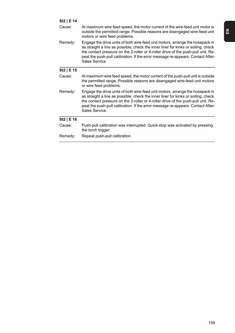
EN
St2 | E 14
Cause: At maximum wire feed speed, the motor current of the wire-feed unit motor is outside the permitted range. Possible reasons are disengaged wire-feed unit motors or wire feed problems.
Remedy: Engage the drive units of both wire-feed unit motors, arrange the hosepack in as straight a line as possible; check the inner liner for kinks or soiling; check the contact pressure on the 2-roller or 4-roller drive of the push-pull unit. Re-peat the push-pull calibration. If the error message re-appears: Contact After-Sales Service
St2 | E 15
Cause: At maximum wire feed speed, the motor current of the push-pull unit is outside the permitted range. Possible reasons are disengaged wire-feed unit motors or wire feed problems.
Remedy: Engage the drive units of both wire-feed unit motors, arrange the hosepack in as straight a line as possible; check the inner liner for kinks or soiling; check the contact pressure on the 2-roller or 4-roller drive of the push-pull unit. Re-peat the push-pull calibration. If the error message re-appears: Contact After-Sales Service.
St2 | E 16
Cause: Push-pull calibration was interrupted: Quick-stop was activated by pressing the torch trigger.
Remedy: Repeat push-pull calibration
159
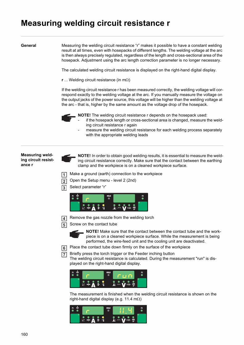
Measuring welding circuit resistance r
General Measuring the welding circuit resistance “r” makes it possible to have a constant welding result at all times, even with hosepacks of different lengths. The welding voltage at the arc is then always precisely regulated, regardless of the length and cross-sectional area of the hosepack. Adjustment using the arc length correction parameter is no longer necessary.
The calculated welding circuit resistance is displayed on the right-hand digital display.
r ... Welding circuit resistance (in m)
If the welding circuit resistance r has been measured correctly, the welding voltage will cor-respond exactly to the welding voltage at the arc. If you manually measure the voltage on the output jacks of the power source, this voltage will be higher than the welding voltage at the arc - that is, higher by the same amount as the voltage drop of the hosepack.
Measuring weld-ing circuit resist-ance r
Make a ground (earth) connection to the workpiece
Open the Setup menu - level 2 (2nd)
Select parameter “r”
Remove the gas nozzle from the welding torch
Screw on the contact tube
Place the contact tube down firmly on the surface of the workpiece
Briefly press the torch trigger or the Feeder inching buttonThe welding circuit resistance is calculated. During the measurement "run" is dis-played on the right-hand digital display.
The measurement is finished when the welding circuit resistance is shown on the right-hand digital display (e.g. 11.4 m)
NOTE! The welding circuit resistance r depends on the hosepack used:- if the hosepack length or cross-sectional area is changed, measure the weld-
ing circuit resistance r again- measure the welding circuit resistance for each welding process separately
with the appropriate welding leads
NOTE! In order to obtain good welding results, it is essential to measure the weld-ing circuit resistance correctly. Make sure that the contact between the earthing clamp and the workpiece is on a cleaned workpiece surface.
123
NOTE! Make sure that the contact between the contact tube and the work-piece is on a cleaned workpiece surface. While the measurement is being performed, the wire-feed unit and the cooling unit are deactivated.
45
67
160

EN
Fit the gas nozzle back onto the welding torch8
161
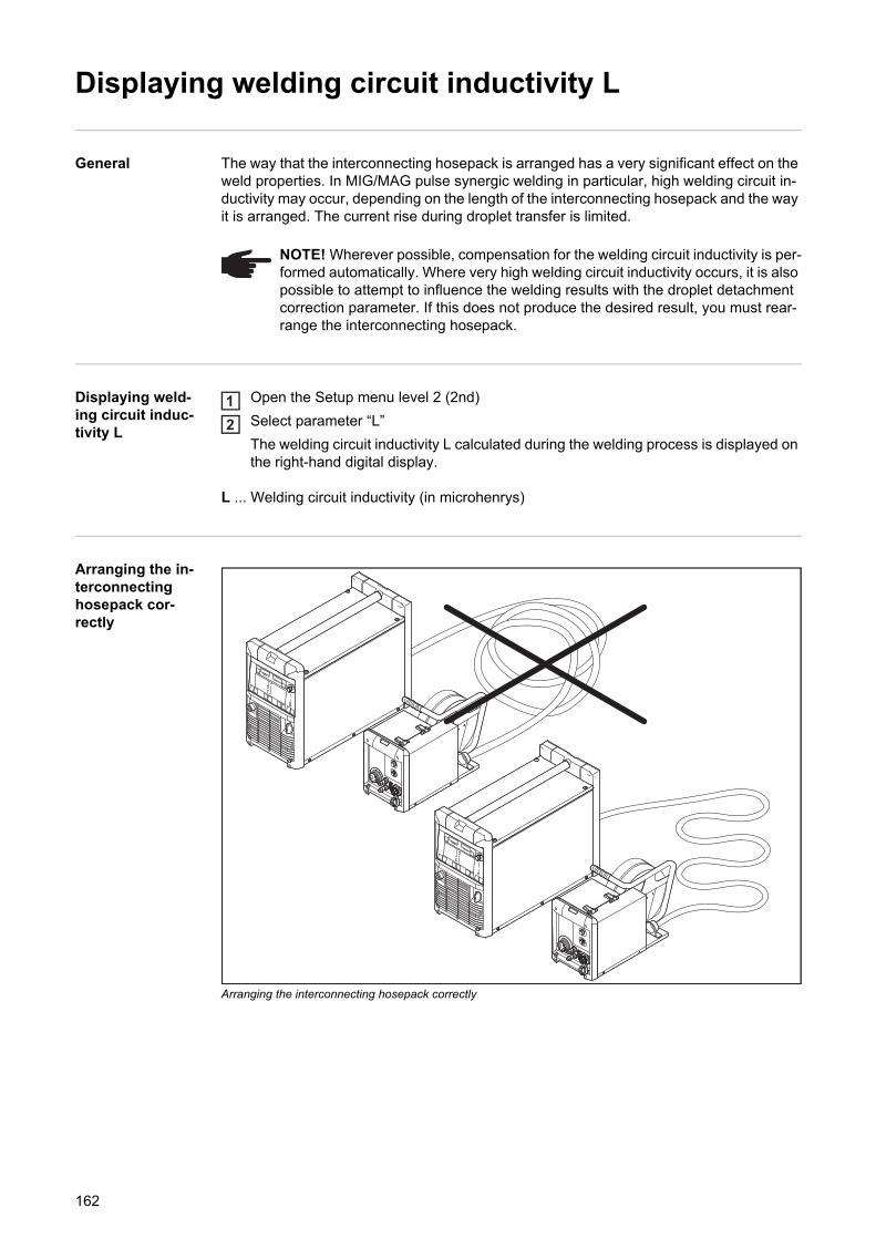
Displaying welding circuit inductivity L
General The way that the interconnecting hosepack is arranged has a very significant effect on the weld properties. In MIG/MAG pulse synergic welding in particular, high welding circuit in-ductivity may occur, depending on the length of the interconnecting hosepack and the way it is arranged. The current rise during droplet transfer is limited.
Displaying weld-ing circuit induc-tivity L
Open the Setup menu level 2 (2nd)
Select parameter “L”
The welding circuit inductivity L calculated during the welding process is displayed on the right-hand digital display.
L ... Welding circuit inductivity (in microhenrys)
Arranging the in-terconnecting hosepack cor-rectly
Arranging the interconnecting hosepack correctly
NOTE! Wherever possible, compensation for the welding circuit inductivity is per-formed automatically. Where very high welding circuit inductivity occurs, it is also possible to attempt to influence the welding results with the droplet detachment correction parameter. If this does not produce the desired result, you must rear-range the interconnecting hosepack.
12
162

Troubleshooting and maintenance

EN
Troubleshooting
General The digital power sources are equipped with an intelligent safety system. This means that apart from the fuse for the coolant pump, it has been possible to dispense with melting-type fuses entirely. After a possible malfunction or error has been remedied, the power source can be put back into normal operation again without any fuses having to be replaced.
Safety
Displayed service codes
If any error message that is not described here appears on the displays, then the fault can only be fixed by a service technician. Make a note of the error message shown in the dis-play and of the serial number and configuration of the power source, and contact our After-Sales Service team with a detailed description of the error.
-St | oP-
Where the power source is being operated with a robot interface or a field bus
Cause: Robot not ready
Remedy: Initialise "Robot ready" signal, initialise "Source error reset" signal ("Source error reset" only available in conjunction with ROB 5000 and field bus coupler for robot control)
dsP | A21
Can only occur when power sources are being operated in parallel or in Twin mode
Cause: The power source is configured for either parallel operation (setup parameter P-C is set to “ON”) or for TimeTwin Digital (setup parameter T-C is set to “ON”). However, the LHSB link has been disconnected or has become faulty while the power source was switched on.
Remedy: Reset the service code: Switch the power source off and back on again. If necessary, restore or repair the LHSB link.
dSP | Axx
Cause: Fault in the central control and regulation unit
Remedy: Contact After-Sales Service
dSP | Cxx
Cause: Fault in the central control and regulation unit
Remedy: Contact After-Sales Service
WARNING! An electric shock can be fatal. Before opening the device- Turn the mains switch to the "O" position- Unplug the machine from the mains- Prevent it from being switched on again- Using a suitable measuring instrument, check to make sure that electrically
charged components (e.g. capacitors) have discharged
CAUTION! Inadequate PE conductor connections can cause serious injury and damage. The housing screws provide a suitable PE conductor connection for earthing (grounding) the housing and must NOT be replaced by any other screws which do not provide a reliable PE conductor connection.
165
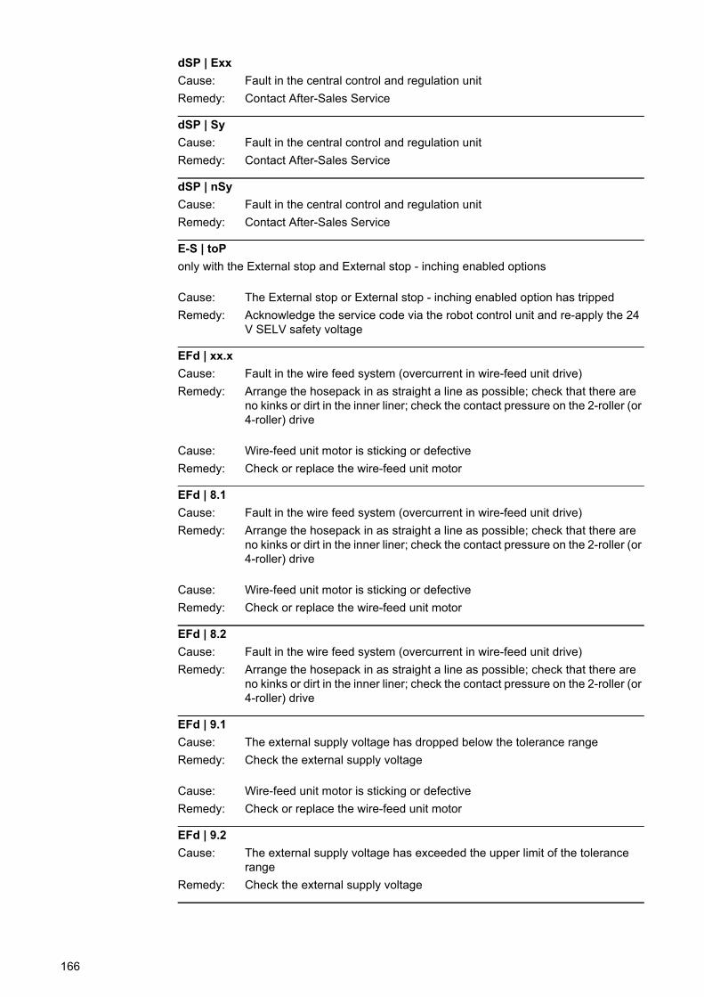
dSP | Exx
Cause: Fault in the central control and regulation unit
Remedy: Contact After-Sales Service
dSP | Sy
Cause: Fault in the central control and regulation unit
Remedy: Contact After-Sales Service
dSP | nSy
Cause: Fault in the central control and regulation unit
Remedy: Contact After-Sales Service
E-S | toP
only with the External stop and External stop - inching enabled options
Cause: The External stop or External stop - inching enabled option has tripped
Remedy: Acknowledge the service code via the robot control unit and re-apply the 24 V SELV safety voltage
EFd | xx.x
Cause: Fault in the wire feed system (overcurrent in wire-feed unit drive)
Remedy: Arrange the hosepack in as straight a line as possible; check that there are no kinks or dirt in the inner liner; check the contact pressure on the 2-roller (or 4-roller) drive
Cause: Wire-feed unit motor is sticking or defective
Remedy: Check or replace the wire-feed unit motor
EFd | 8.1
Cause: Fault in the wire feed system (overcurrent in wire-feed unit drive)
Remedy: Arrange the hosepack in as straight a line as possible; check that there are no kinks or dirt in the inner liner; check the contact pressure on the 2-roller (or 4-roller) drive
Cause: Wire-feed unit motor is sticking or defective
Remedy: Check or replace the wire-feed unit motor
EFd | 8.2
Cause: Fault in the wire feed system (overcurrent in wire-feed unit drive)
Remedy: Arrange the hosepack in as straight a line as possible; check that there are no kinks or dirt in the inner liner; check the contact pressure on the 2-roller (or 4-roller) drive
EFd | 9.1
Cause: The external supply voltage has dropped below the tolerance range
Remedy: Check the external supply voltage
Cause: Wire-feed unit motor is sticking or defective
Remedy: Check or replace the wire-feed unit motor
EFd | 9.2
Cause: The external supply voltage has exceeded the upper limit of the tolerance range
Remedy: Check the external supply voltage
166
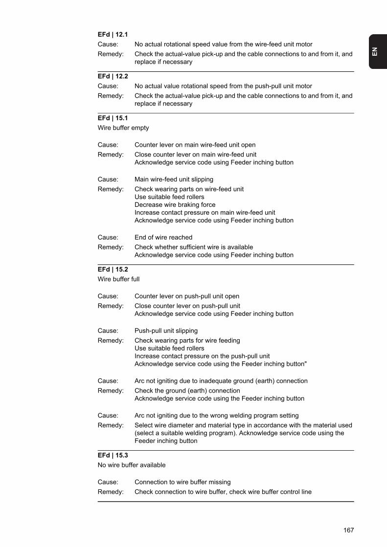
EN
EFd | 12.1
Cause: No actual rotational speed value from the wire-feed unit motor
Remedy: Check the actual-value pick-up and the cable connections to and from it, and replace if necessary
EFd | 12.2
Cause: No actual value rotational speed from the push-pull unit motor
Remedy: Check the actual-value pick-up and the cable connections to and from it, and replace if necessary
EFd | 15.1
Wire buffer empty
Cause: Counter lever on main wire-feed unit open
Remedy: Close counter lever on main wire-feed unitAcknowledge service code using Feeder inching button
Cause: Main wire-feed unit slipping
Remedy: Check wearing parts on wire-feed unitUse suitable feed rollersDecrease wire braking forceIncrease contact pressure on main wire-feed unitAcknowledge service code using Feeder inching button
Cause: End of wire reached
Remedy: Check whether sufficient wire is availableAcknowledge service code using Feeder inching button
EFd | 15.2
Wire buffer full
Cause: Counter lever on push-pull unit open
Remedy: Close counter lever on push-pull unitAcknowledge service code using Feeder inching button
Cause: Push-pull unit slipping
Remedy: Check wearing parts for wire feedingUse suitable feed rollersIncrease contact pressure on the push-pull unitAcknowledge service code using the Feeder inching button"
Cause: Arc not igniting due to inadequate ground (earth) connection
Remedy: Check the ground (earth) connectionAcknowledge service code using the Feeder inching button
Cause: Arc not igniting due to the wrong welding program setting
Remedy: Select wire diameter and material type in accordance with the material used (select a suitable welding program). Acknowledge service code using the Feeder inching button
EFd | 15.3
No wire buffer available
Cause: Connection to wire buffer missing
Remedy: Check connection to wire buffer, check wire buffer control line
167
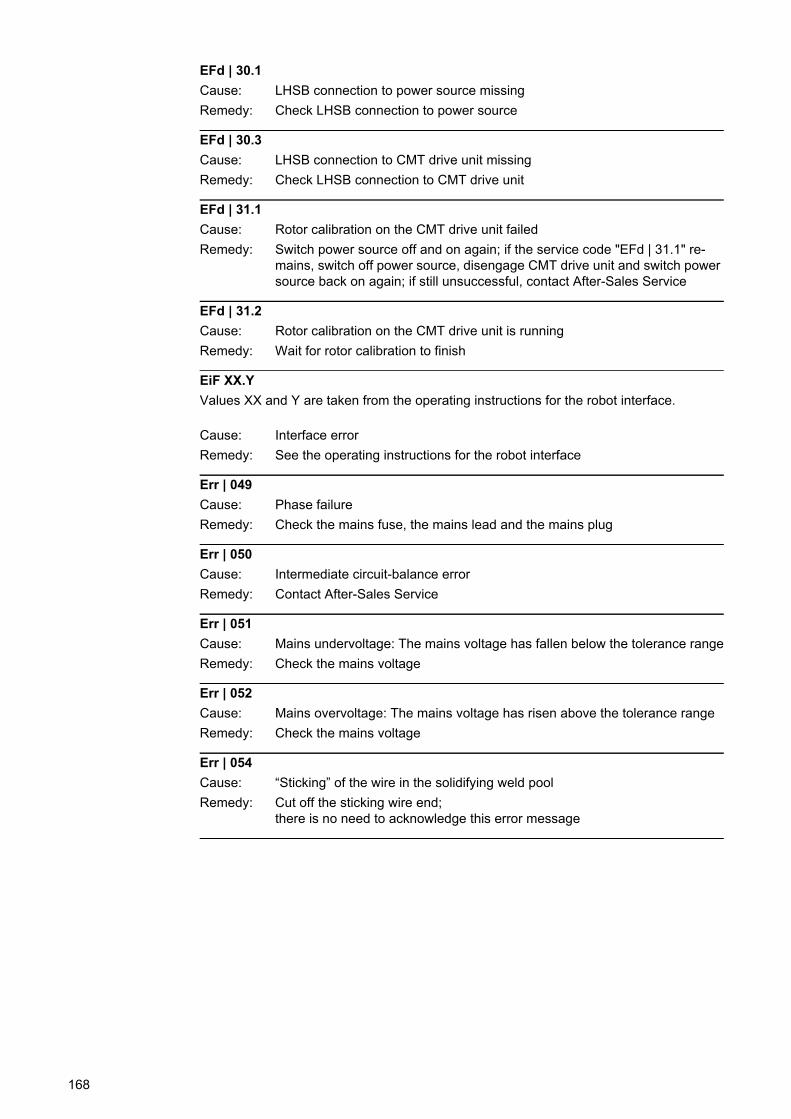
EFd | 30.1
Cause: LHSB connection to power source missing
Remedy: Check LHSB connection to power source
EFd | 30.3
Cause: LHSB connection to CMT drive unit missing
Remedy: Check LHSB connection to CMT drive unit
EFd | 31.1
Cause: Rotor calibration on the CMT drive unit failed
Remedy: Switch power source off and on again; if the service code "EFd | 31.1" re-mains, switch off power source, disengage CMT drive unit and switch power source back on again; if still unsuccessful, contact After-Sales Service
EFd | 31.2
Cause: Rotor calibration on the CMT drive unit is running
Remedy: Wait for rotor calibration to finish
EiF XX.Y
Values XX and Y are taken from the operating instructions for the robot interface.
Cause: Interface error
Remedy: See the operating instructions for the robot interface
Err | 049
Cause: Phase failure
Remedy: Check the mains fuse, the mains lead and the mains plug
Err | 050
Cause: Intermediate circuit-balance error
Remedy: Contact After-Sales Service
Err | 051
Cause: Mains undervoltage: The mains voltage has fallen below the tolerance range
Remedy: Check the mains voltage
Err | 052
Cause: Mains overvoltage: The mains voltage has risen above the tolerance range
Remedy: Check the mains voltage
Err | 054
Cause: “Sticking” of the wire in the solidifying weld pool
Remedy: Cut off the sticking wire end;there is no need to acknowledge this error message
168
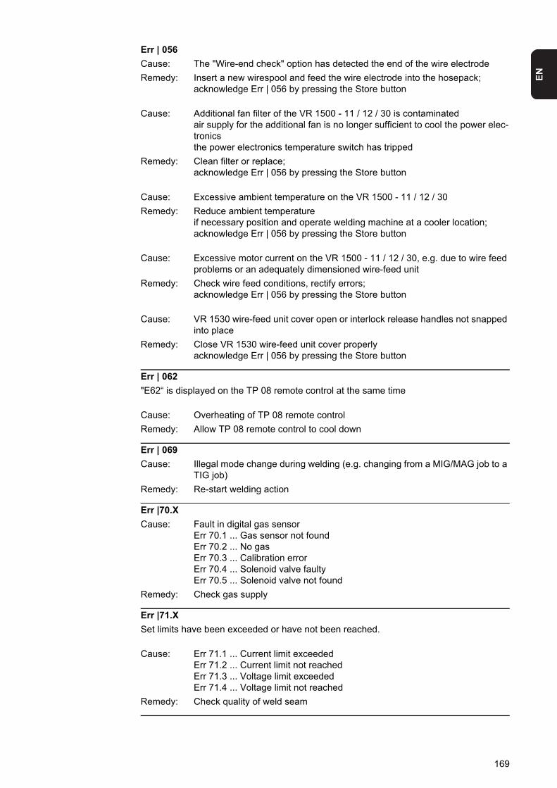
EN
Err | 056
Cause: The "Wire-end check" option has detected the end of the wire electrode
Remedy: Insert a new wirespool and feed the wire electrode into the hosepack;acknowledge Err | 056 by pressing the Store button
Cause: Additional fan filter of the VR 1500 - 11 / 12 / 30 is contaminatedair supply for the additional fan is no longer sufficient to cool the power elec-tronicsthe power electronics temperature switch has tripped
Remedy: Clean filter or replace;acknowledge Err | 056 by pressing the Store button
Cause: Excessive ambient temperature on the VR 1500 - 11 / 12 / 30
Remedy: Reduce ambient temperatureif necessary position and operate welding machine at a cooler location;acknowledge Err | 056 by pressing the Store button
Cause: Excessive motor current on the VR 1500 - 11 / 12 / 30, e.g. due to wire feed problems or an adequately dimensioned wire-feed unit
Remedy: Check wire feed conditions, rectify errors;acknowledge Err | 056 by pressing the Store button
Cause: VR 1530 wire-feed unit cover open or interlock release handles not snapped into place
Remedy: Close VR 1530 wire-feed unit cover properlyacknowledge Err | 056 by pressing the Store button
Err | 062
"E62“ is displayed on the TP 08 remote control at the same time
Cause: Overheating of TP 08 remote control
Remedy: Allow TP 08 remote control to cool down
Err | 069
Cause: Illegal mode change during welding (e.g. changing from a MIG/MAG job to a TIG job)
Remedy: Re-start welding action
Err |70.X
Cause: Fault in digital gas sensorErr 70.1 ... Gas sensor not foundErr 70.2 ... No gasErr 70.3 ... Calibration errorErr 70.4 ... Solenoid valve faultyErr 70.5 ... Solenoid valve not found
Remedy: Check gas supply
Err |71.X
Set limits have been exceeded or have not been reached.
Cause: Err 71.1 ... Current limit exceededErr 71.2 ... Current limit not reachedErr 71.3 ... Voltage limit exceededErr 71.4 ... Voltage limit not reached
Remedy: Check quality of weld seam
169
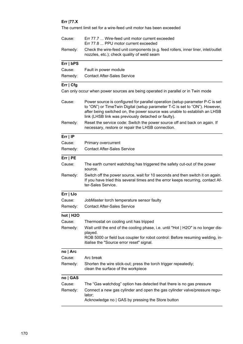
Err |77.X
The current limit set for a wire-feed unit motor has been exceeded
Cause: Err 77.7 ... Wire-feed unit motor current exceededErr 77.8 ... PPU motor current exceeded
Remedy: Check the wire-feed unit components (e.g. feed rollers, inner liner, inlet/outlet nozzles, etc.); check quality of weld seam
Err | bPS
Cause: Fault in power module
Remedy: Contact After-Sales Service
Err | Cfg
Can only occur when power sources are being operated in parallel or in Twin mode
Cause: Power source is configured for parallel operation (setup parameter P-C is set to “ON”) or TimeTwin Digital (setup parameter T-C is set to “ON”). However, after being switched on, the power source was unable to establish an LHSB link (LHSB link was previously detached or faulty).
Remedy: Reset the service code: Switch the power source off and back on again. If necessary, restore or repair the LHSB connection.
Err | IP
Cause: Primary overcurrent
Remedy: Contact After-Sales Service
Err | PE
Cause: The earth current watchdog has triggered the safety cut-out of the power source.
Remedy: Switch off the power source, wait for 10 seconds and then switch it on again. If you have tried this several times and the error keeps recurring, contact Af-ter-Sales Service.
Err | tJo
Cause: JobMaster torch temperature sensor faulty
Remedy: Contact After-Sales Service
hot | H2O
Cause: Thermostat on cooling unit has tripped
Remedy: Wait until the end of the cooling phase, i.e. until "Hot | H2O" is no longer dis-played.ROB 5000 or field bus coupler for robot control: Before resuming welding, in-itialise the "Source error reset" signal.
no | Arc
Cause: Arc break
Remedy: Shorten the wire stick-out; press the torch trigger repeatedly;clean the surface of the workpiece
no | GAS
Cause: The “Gas watchdog” option has detected that there is no gas pressure
Remedy: Connect a new gas cylinder and open the gas cylinder valve/pressure regu-lator; Acknowledge no | GAS by pressing the Store button
170
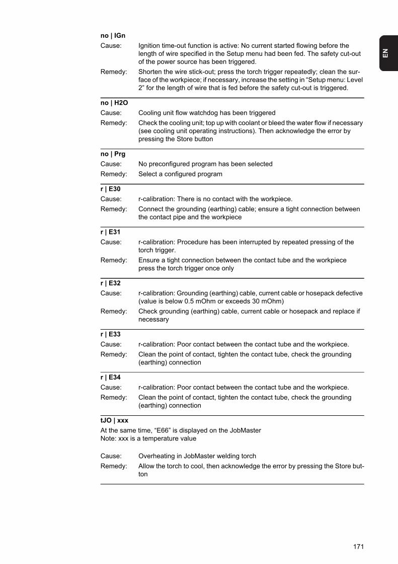
EN
no | IGn
Cause: Ignition time-out function is active: No current started flowing before the length of wire specified in the Setup menu had been fed. The safety cut-out of the power source has been triggered.
Remedy: Shorten the wire stick-out; press the torch trigger repeatedly; clean the sur-face of the workpiece; if necessary, increase the setting in “Setup menu: Level 2” for the length of wire that is fed before the safety cut-out is triggered.
no | H2O
Cause: Cooling unit flow watchdog has been triggered
Remedy: Check the cooling unit; top up with coolant or bleed the water flow if necessary (see cooling unit operating instructions). Then acknowledge the error by pressing the Store button
no | Prg
Cause: No preconfigured program has been selected
Remedy: Select a configured program
r | E30
Cause: r-calibration: There is no contact with the workpiece.
Remedy: Connect the grounding (earthing) cable; ensure a tight connection between the contact pipe and the workpiece
r | E31
Cause: r-calibration: Procedure has been interrupted by repeated pressing of the torch trigger.
Remedy: Ensure a tight connection between the contact tube and the workpiecepress the torch trigger once only
r | E32
Cause: r-calibration: Grounding (earthing) cable, current cable or hosepack defective (value is below 0.5 mOhm or exceeds 30 mOhm)
Remedy: Check grounding (earthing) cable, current cable or hosepack and replace if necessary
r | E33
Cause: r-calibration: Poor contact between the contact tube and the workpiece.
Remedy: Clean the point of contact, tighten the contact tube, check the grounding (earthing) connection
r | E34
Cause: r-calibration: Poor contact between the contact tube and the workpiece.
Remedy: Clean the point of contact, tighten the contact tube, check the grounding (earthing) connection
tJO | xxx
At the same time, “E66” is displayed on the JobMasterNote: xxx is a temperature value
Cause: Overheating in JobMaster welding torch
Remedy: Allow the torch to cool, then acknowledge the error by pressing the Store but-ton
171
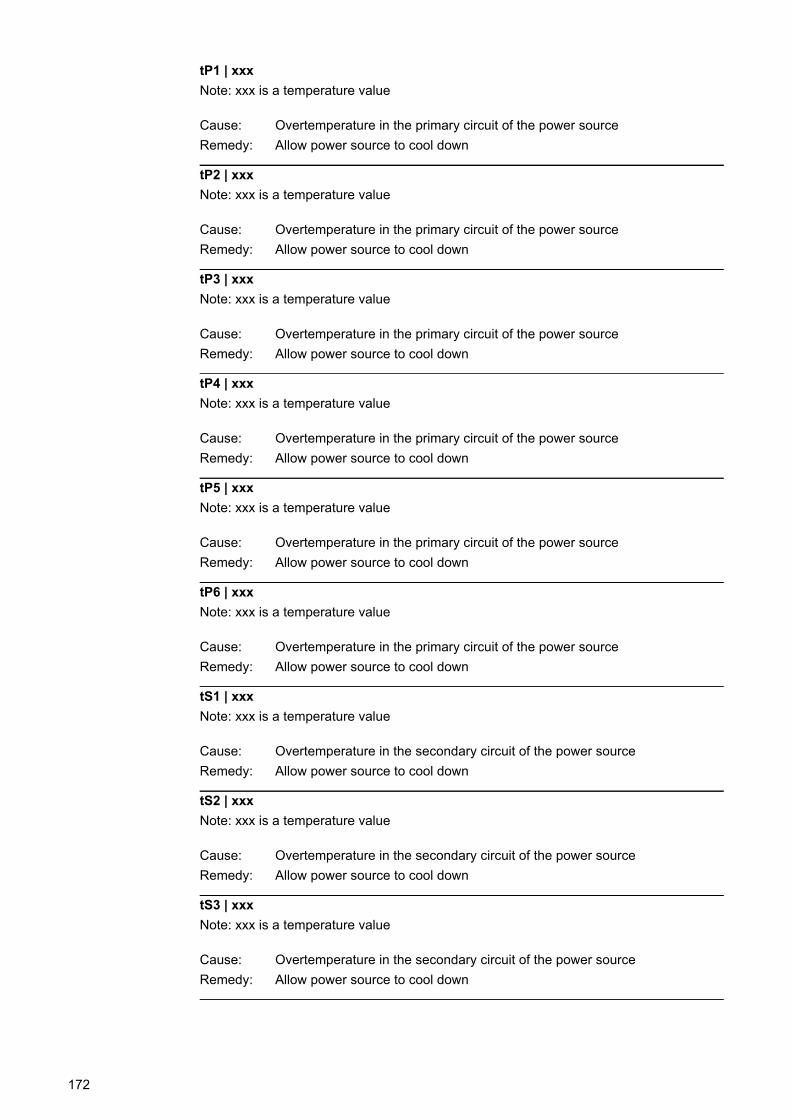
tP1 | xxx
Note: xxx is a temperature value
Cause: Overtemperature in the primary circuit of the power source
Remedy: Allow power source to cool down
tP2 | xxx
Note: xxx is a temperature value
Cause: Overtemperature in the primary circuit of the power source
Remedy: Allow power source to cool down
tP3 | xxx
Note: xxx is a temperature value
Cause: Overtemperature in the primary circuit of the power source
Remedy: Allow power source to cool down
tP4 | xxx
Note: xxx is a temperature value
Cause: Overtemperature in the primary circuit of the power source
Remedy: Allow power source to cool down
tP5 | xxx
Note: xxx is a temperature value
Cause: Overtemperature in the primary circuit of the power source
Remedy: Allow power source to cool down
tP6 | xxx
Note: xxx is a temperature value
Cause: Overtemperature in the primary circuit of the power source
Remedy: Allow power source to cool down
tS1 | xxx
Note: xxx is a temperature value
Cause: Overtemperature in the secondary circuit of the power source
Remedy: Allow power source to cool down
tS2 | xxx
Note: xxx is a temperature value
Cause: Overtemperature in the secondary circuit of the power source
Remedy: Allow power source to cool down
tS3 | xxx
Note: xxx is a temperature value
Cause: Overtemperature in the secondary circuit of the power source
Remedy: Allow power source to cool down
172
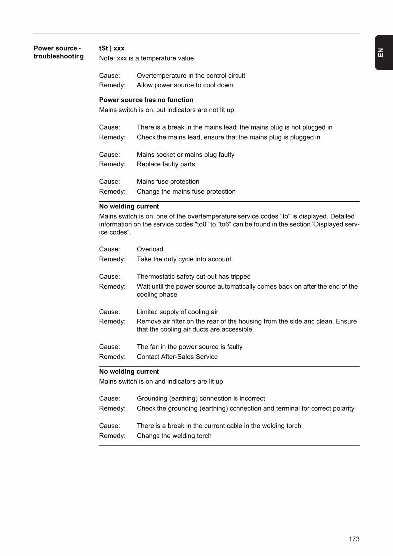
EN
Power source -troubleshootingtSt | xxx
Note: xxx is a temperature value
Cause: Overtemperature in the control circuit
Remedy: Allow power source to cool down
Power source has no function
Mains switch is on, but indicators are not lit up
Cause: There is a break in the mains lead; the mains plug is not plugged in
Remedy: Check the mains lead, ensure that the mains plug is plugged in
Cause: Mains socket or mains plug faulty
Remedy: Replace faulty parts
Cause: Mains fuse protection
Remedy: Change the mains fuse protection
No welding current
Mains switch is on, one of the overtemperature service codes "to" is displayed. Detailed information on the service codes "to0" to "to6" can be found in the section "Displayed serv-ice codes".
Cause: Overload
Remedy: Take the duty cycle into account
Cause: Thermostatic safety cut-out has tripped
Remedy: Wait until the power source automatically comes back on after the end of the cooling phase
Cause: Limited supply of cooling air
Remedy: Remove air filter on the rear of the housing from the side and clean. Ensure that the cooling air ducts are accessible.
Cause: The fan in the power source is faulty
Remedy: Contact After-Sales Service
No welding current
Mains switch is on and indicators are lit up
Cause: Grounding (earthing) connection is incorrect
Remedy: Check the grounding (earthing) connection and terminal for correct polarity
Cause: There is a break in the current cable in the welding torch
Remedy: Change the welding torch
173
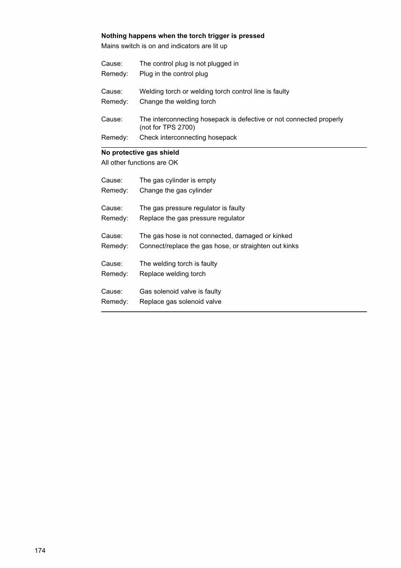
Nothing happens when the torch trigger is pressed
Mains switch is on and indicators are lit up
Cause: The control plug is not plugged in
Remedy: Plug in the control plug
Cause: Welding torch or welding torch control line is faulty
Remedy: Change the welding torch
Cause: The interconnecting hosepack is defective or not connected properly(not for TPS 2700)
Remedy: Check interconnecting hosepack
No protective gas shield
All other functions are OK
Cause: The gas cylinder is empty
Remedy: Change the gas cylinder
Cause: The gas pressure regulator is faulty
Remedy: Replace the gas pressure regulator
Cause: The gas hose is not connected, damaged or kinked
Remedy: Connect/replace the gas hose, or straighten out kinks
Cause: The welding torch is faulty
Remedy: Replace welding torch
Cause: Gas solenoid valve is faulty
Remedy: Replace gas solenoid valve
174
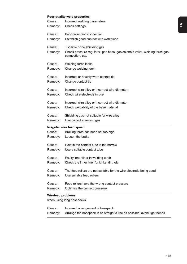
EN
Poor-quality weld properties
Cause: Incorrect welding parameters
Remedy: Check settings
Cause: Poor grounding connection
Remedy: Establish good contact with workpiece
Cause: Too little or no shielding gas
Remedy: Check pressure regulator, gas hose, gas solenoid valve, welding torch gas connection, etc.
Cause: Welding torch leaks
Remedy: Change welding torch
Cause: Incorrect or heavily worn contact tip
Remedy: Change contact tip
Cause: Incorrect wire alloy or incorrect wire diameter
Remedy: Check wire electrode in use
Cause: Incorrect wire alloy or incorrect wire diameter
Remedy: Check weldability of the base material
Cause: Shielding gas not suitable for wire alloy
Remedy: Use correct shielding gas
Irregular wire feed speed
Cause: Braking force has been set too high
Remedy: Loosen the brake
Cause: Hole in the contact tube is too narrow
Remedy: Use a suitable contact tube
Cause: Faulty inner liner in welding torch
Remedy: Check the inner liner for kinks, dirt, etc.
Cause: The feed rollers are not suitable for the wire electrode being used
Remedy: Use suitable feed rollers
Cause: Feed rollers have the wrong contact pressure
Remedy: Optimise the contact pressure
Wirefeed problems
when using long hosepacks
Cause: Incorrect arrangement of hosepack
Remedy: Arrange the hosepack in as straight a line as possible, avoid tight bends
175

The welding torch becomes very hot
Cause: The dimensions of the welding torch are inadequate
Remedy: Observe the duty cycle and loading limits
Cause: Only on water-cooled machines: Inadequate coolant flow
Remedy: Check coolant fill level, coolant flow, for coolant contamination, etc.
176
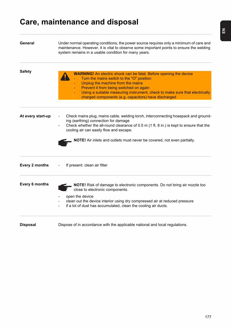
EN
Care, maintenance and disposal
General Under normal operating conditions, the power source requires only a minimum of care and maintenance. However, it is vital to observe some important points to ensure the welding system remains in a usable condition for many years.
Safety
At every start-up - Check mains plug, mains cable, welding torch, interconnecting hosepack and ground-ing (earthing) connection for damage
- Check whether the all-round clearance of 0.5 m (1 ft. 8 in.) is kept to ensure that the cooling air can easily flow and escape.
Every 2 months - If present: clean air filter
Every 6 months
- open the device- clean out the device interior using dry compressed air at reduced pressure- if a lot of dust has accumulated, clean the cooling air ducts.
Disposal Dispose of in accordance with the applicable national and local regulations.
WARNING! An electric shock can be fatal. Before opening the device- Turn the mains switch to the "O" position- Unplug the machine from the mains- Prevent it from being switched on again- Using a suitable measuring instrument, check to make sure that electrically
charged components (e.g. capacitors) have discharged
NOTE! Air inlets and outlets must never be covered, not even partially.
NOTE! Risk of damage to electronic components. Do not bring air nozzle too close to electronic components.
177

178

Appendix

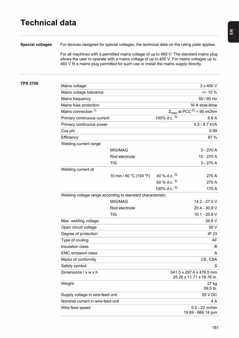
EN
Technical data
Special voltages For devices designed for special voltages, the technical data on the rating plate applies.
For all machines with a permitted mains voltage of up to 460 V: The standard mains plug allows the user to operate with a mains voltage of up to 400 V. For mains voltages up to 460 V fit a mains plug permitted for such use or install the mains supply directly.
TPS 2700Mains voltage 3 x 400 V
Mains voltage tolerance +/- 15 %
Mains frequency 50 / 60 Hz
Mains fuse protection 16 A slow-blow
Mains connection 1) Zmax at PCC 2) = 95 mOhm
Primary continuous current 100% d.c. 3) 6.6 A
Primary continuous power 4.5 - 8.7 kVA
Cos phi 0.99
Efficiency 87 %
Welding current range
MIG/MAG 3 - 270 A
Rod electrode 10 - 270 A
TIG 3 - 270 A
Welding current at
10 min / 40 °C (104 °F) 40 % d.c. 3) 270 A
60 % d.c. 3) 270 A
100% d.c. 3) 170 A
Welding voltage range according to standard characteristic
MIG/MAG 14.2 - 27.5 V
Rod electrode 20.4 - 30.8 V
TIG 10.1 - 20.8 V
Max. welding voltage 34.6 V
Open circuit voltage 50 V
Degree of protection IP 23
Type of cooling AF
Insulation class B
EMC emission class A
Marks of conformity CE, CSA
Safety symbol S
Dimensions l x w x h 641.5 x 297.4 x 476.5 mm25.26 x 11.71 x 18.76 in.
Weight 27 kg59.5 lb.
Supply voltage in wire-feed unit 55 V DC
Nominal current in wire-feed unit 4 A
Wire feed speed 0.5 - 22 m/min19.69 - 866.14 ipm
181
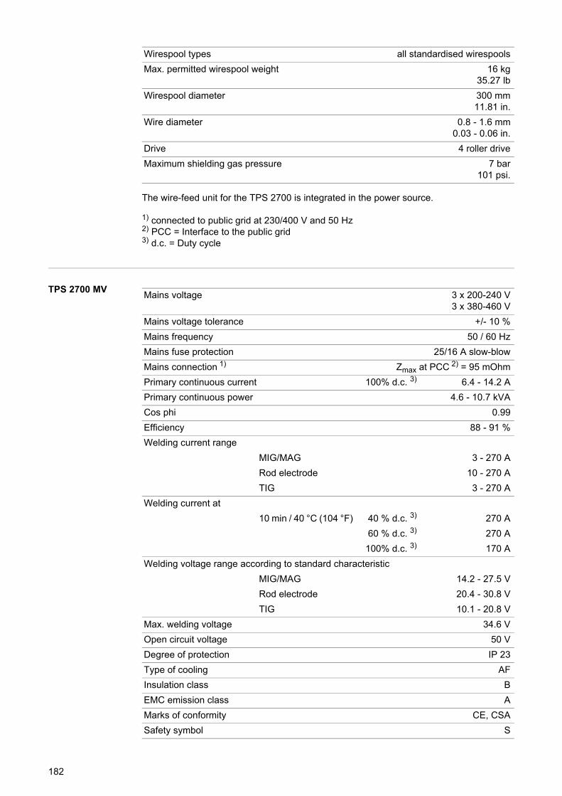
The wire-feed unit for the TPS 2700 is integrated in the power source.
1) connected to public grid at 230/400 V and 50 Hz2) PCC = Interface to the public grid3) d.c. = Duty cycle
TPS 2700 MV
Wirespool types all standardised wirespools
Max. permitted wirespool weight 16 kg35.27 lb
Wirespool diameter 300 mm11.81 in.
Wire diameter 0.8 - 1.6 mm0.03 - 0.06 in.
Drive 4 roller drive
Maximum shielding gas pressure 7 bar101 psi.
Mains voltage 3 x 200-240 V3 x 380-460 V
Mains voltage tolerance +/- 10 %
Mains frequency 50 / 60 Hz
Mains fuse protection 25/16 A slow-blow
Mains connection 1) Zmax at PCC 2) = 95 mOhm
Primary continuous current 100% d.c. 3) 6.4 - 14.2 A
Primary continuous power 4.6 - 10.7 kVA
Cos phi 0.99
Efficiency 88 - 91 %
Welding current range
MIG/MAG 3 - 270 A
Rod electrode 10 - 270 A
TIG 3 - 270 A
Welding current at
10 min / 40 °C (104 °F) 40 % d.c. 3) 270 A
60 % d.c. 3) 270 A
100% d.c. 3) 170 A
Welding voltage range according to standard characteristic
MIG/MAG 14.2 - 27.5 V
Rod electrode 20.4 - 30.8 V
TIG 10.1 - 20.8 V
Max. welding voltage 34.6 V
Open circuit voltage 50 V
Degree of protection IP 23
Type of cooling AF
Insulation class B
EMC emission class A
Marks of conformity CE, CSA
Safety symbol S
182
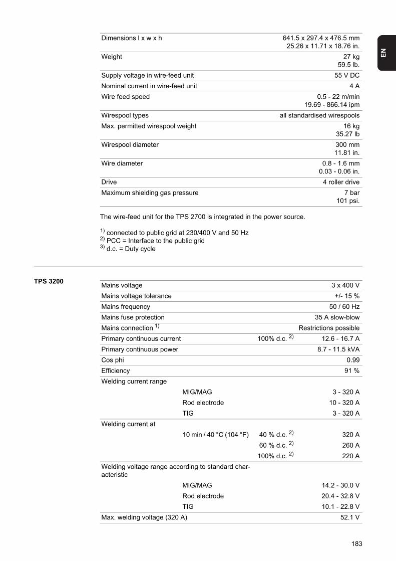
EN
The wire-feed unit for the TPS 2700 is integrated in the power source.
1) connected to public grid at 230/400 V and 50 Hz2) PCC = Interface to the public grid3) d.c. = Duty cycle
TPS 3200
Dimensions l x w x h 641.5 x 297.4 x 476.5 mm25.26 x 11.71 x 18.76 in.
Weight 27 kg59.5 lb.
Supply voltage in wire-feed unit 55 V DC
Nominal current in wire-feed unit 4 A
Wire feed speed 0.5 - 22 m/min19.69 - 866.14 ipm
Wirespool types all standardised wirespools
Max. permitted wirespool weight 16 kg35.27 lb
Wirespool diameter 300 mm11.81 in.
Wire diameter 0.8 - 1.6 mm0.03 - 0.06 in.
Drive 4 roller drive
Maximum shielding gas pressure 7 bar101 psi.
Mains voltage 3 x 400 V
Mains voltage tolerance +/- 15 %
Mains frequency 50 / 60 Hz
Mains fuse protection 35 A slow-blow
Mains connection 1) Restrictions possible
Primary continuous current 100% d.c. 2) 12.6 - 16.7 A
Primary continuous power 8.7 - 11.5 kVA
Cos phi 0.99
Efficiency 91 %
Welding current range
MIG/MAG 3 - 320 A
Rod electrode 10 - 320 A
TIG 3 - 320 A
Welding current at
10 min / 40 °C (104 °F) 40 % d.c. 2) 320 A
60 % d.c. 2) 260 A
100% d.c. 2) 220 A
Welding voltage range according to standard char-acteristic
MIG/MAG 14.2 - 30.0 V
Rod electrode 20.4 - 32.8 V
TIG 10.1 - 22.8 V
Max. welding voltage (320 A) 52.1 V
183
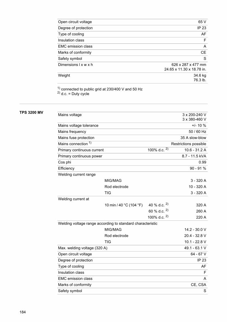
1) connected to public grid at 230/400 V and 50 Hz2) d.c. = Duty cycle
TPS 3200 MV
Open circuit voltage 65 V
Degree of protection IP 23
Type of cooling AF
Insulation class F
EMC emission class A
Marks of conformity CE
Safety symbol S
Dimensions l x w x h 626 x 287 x 477 mm24.65 x 11.30 x 18.78 in.
Weight 34.6 kg76.3 lb.
Mains voltage 3 x 200-240 V3 x 380-460 V
Mains voltage tolerance +/- 10 %
Mains frequency 50 / 60 Hz
Mains fuse protection 35 A slow-blow
Mains connection 1) Restrictions possible
Primary continuous current 100% d.c. 2) 10.6 - 31.2 A
Primary continuous power 8.7 - 11.5 kVA
Cos phi 0.99
Efficiency 90 - 91 %
Welding current range
MIG/MAG 3 - 320 A
Rod electrode 10 - 320 A
TIG 3 - 320 A
Welding current at
10 min / 40 °C (104 °F) 40 % d.c. 2) 320 A
60 % d.c. 2) 260 A
100% d.c. 2) 220 A
Welding voltage range according to standard characteristic
MIG/MAG 14.2 - 30.0 V
Rod electrode 20.4 - 32.8 V
TIG 10.1 - 22.8 V
Max. welding voltage (320 A) 49.1 - 63.1 V
Open circuit voltage 64 - 67 V
Degree of protection IP 23
Type of cooling AF
Insulation class F
EMC emission class A
Marks of conformity CE, CSA
Safety symbol S
184
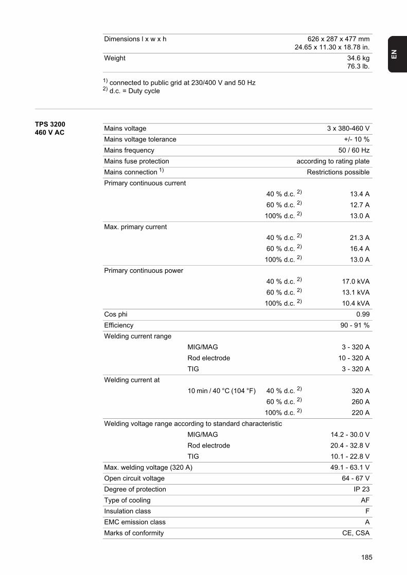
EN
1) connected to public grid at 230/400 V and 50 Hz2) d.c. = Duty cycle
TPS 3200 460 V AC
Dimensions l x w x h 626 x 287 x 477 mm24.65 x 11.30 x 18.78 in.
Weight 34.6 kg76.3 lb.
Mains voltage 3 x 380-460 V
Mains voltage tolerance +/- 10 %
Mains frequency 50 / 60 Hz
Mains fuse protection according to rating plate
Mains connection 1) Restrictions possible
Primary continuous current
40 % d.c. 2) 13.4 A
60 % d.c. 2) 12.7 A
100% d.c. 2) 13.0 A
Max. primary current
40 % d.c. 2) 21.3 A
60 % d.c. 2) 16.4 A
100% d.c. 2) 13.0 A
Primary continuous power
40 % d.c. 2) 17.0 kVA
60 % d.c. 2) 13.1 kVA
100% d.c. 2) 10.4 kVA
Cos phi 0.99
Efficiency 90 - 91 %
Welding current range
MIG/MAG 3 - 320 A
Rod electrode 10 - 320 A
TIG 3 - 320 A
Welding current at
10 min / 40 °C (104 °F) 40 % d.c. 2) 320 A
60 % d.c. 2) 260 A
100% d.c. 2) 220 A
Welding voltage range according to standard characteristic
MIG/MAG 14.2 - 30.0 V
Rod electrode 20.4 - 32.8 V
TIG 10.1 - 22.8 V
Max. welding voltage (320 A) 49.1 - 63.1 V
Open circuit voltage 64 - 67 V
Degree of protection IP 23
Type of cooling AF
Insulation class F
EMC emission class A
Marks of conformity CE, CSA
185
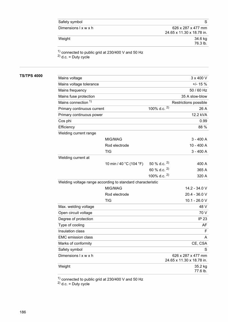
1) connected to public grid at 230/400 V and 50 Hz2) d.c. = Duty cycle
TS/TPS 4000
1) connected to public grid at 230/400 V and 50 Hz2) d.c. = Duty cycle
Safety symbol S
Dimensions l x w x h 626 x 287 x 477 mm24.65 x 11.30 x 18.78 in.
Weight 34.6 kg76.3 lb.
Mains voltage 3 x 400 V
Mains voltage tolerance +/- 15 %
Mains frequency 50 / 60 Hz
Mains fuse protection 35 A slow-blow
Mains connection 1) Restrictions possible
Primary continuous current 100% d.c. 2) 26 A
Primary continuous power 12.2 kVA
Cos phi 0.99
Efficiency 88 %
Welding current range
MIG/MAG 3 - 400 A
Rod electrode 10 - 400 A
TIG 3 - 400 A
Welding current at
10 min / 40 °C (104 °F) 50 % d.c. 2) 400 A
60 % d.c. 2) 365 A
100% d.c. 2) 320 A
Welding voltage range according to standard characteristic
MIG/MAG 14.2 - 34.0 V
Rod electrode 20.4 - 36.0 V
TIG 10.1 - 26.0 V
Max. welding voltage 48 V
Open circuit voltage 70 V
Degree of protection IP 23
Type of cooling AF
Insulation class F
EMC emission class A
Marks of conformity CE, CSA
Safety symbol S
Dimensions l x w x h 626 x 287 x 477 mm24.65 x 11.30 x 18.78 in.
Weight 35.2 kg77.6 lb.
186
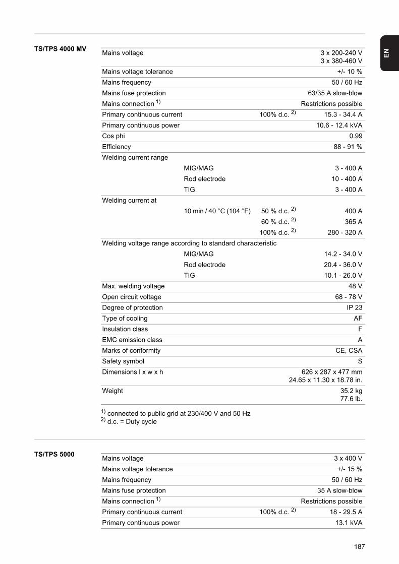
EN
TS/TPS 4000 MV1) connected to public grid at 230/400 V and 50 Hz2) d.c. = Duty cycle
TS/TPS 5000
Mains voltage 3 x 200-240 V3 x 380-460 V
Mains voltage tolerance +/- 10 %
Mains frequency 50 / 60 Hz
Mains fuse protection 63/35 A slow-blow
Mains connection 1) Restrictions possible
Primary continuous current 100% d.c. 2) 15.3 - 34.4 A
Primary continuous power 10.6 - 12.4 kVA
Cos phi 0.99
Efficiency 88 - 91 %
Welding current range
MIG/MAG 3 - 400 A
Rod electrode 10 - 400 A
TIG 3 - 400 A
Welding current at
10 min / 40 °C (104 °F) 50 % d.c. 2) 400 A
60 % d.c. 2) 365 A
100% d.c. 2) 280 - 320 A
Welding voltage range according to standard characteristic
MIG/MAG 14.2 - 34.0 V
Rod electrode 20.4 - 36.0 V
TIG 10.1 - 26.0 V
Max. welding voltage 48 V
Open circuit voltage 68 - 78 V
Degree of protection IP 23
Type of cooling AF
Insulation class F
EMC emission class A
Marks of conformity CE, CSA
Safety symbol S
Dimensions l x w x h 626 x 287 x 477 mm24.65 x 11.30 x 18.78 in.
Weight 35.2 kg77.6 lb.
Mains voltage 3 x 400 V
Mains voltage tolerance +/- 15 %
Mains frequency 50 / 60 Hz
Mains fuse protection 35 A slow-blow
Mains connection 1) Restrictions possible
Primary continuous current 100% d.c. 2) 18 - 29.5 A
Primary continuous power 13.1 kVA
187
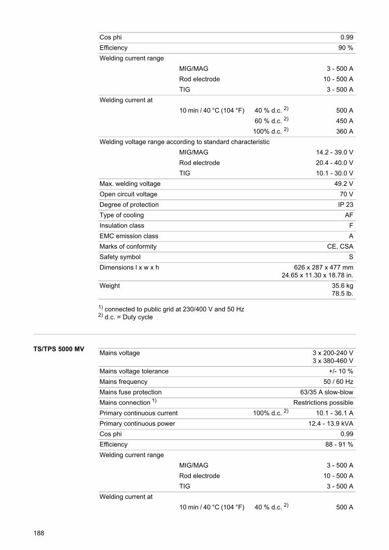
1) connected to public grid at 230/400 V and 50 Hz2) d.c. = Duty cycle
TS/TPS 5000 MV
Cos phi 0.99
Efficiency 90 %
Welding current range
MIG/MAG 3 - 500 A
Rod electrode 10 - 500 A
TIG 3 - 500 A
Welding current at
10 min / 40 °C (104 °F) 40 % d.c. 2) 500 A
60 % d.c. 2) 450 A
100% d.c. 2) 360 A
Welding voltage range according to standard characteristic
MIG/MAG 14.2 - 39.0 V
Rod electrode 20.4 - 40.0 V
TIG 10.1 - 30.0 V
Max. welding voltage 49.2 V
Open circuit voltage 70 V
Degree of protection IP 23
Type of cooling AF
Insulation class F
EMC emission class A
Marks of conformity CE, CSA
Safety symbol S
Dimensions l x w x h 626 x 287 x 477 mm24.65 x 11.30 x 18.78 in.
Weight 35.6 kg78.5 lb.
Mains voltage 3 x 200-240 V3 x 380-460 V
Mains voltage tolerance +/- 10 %
Mains frequency 50 / 60 Hz
Mains fuse protection 63/35 A slow-blow
Mains connection 1) Restrictions possible
Primary continuous current 100% d.c. 2) 10.1 - 36.1 A
Primary continuous power 12.4 - 13.9 kVA
Cos phi 0.99
Efficiency 88 - 91 %
Welding current range
MIG/MAG 3 - 500 A
Rod electrode 10 - 500 A
TIG 3 - 500 A
Welding current at
10 min / 40 °C (104 °F) 40 % d.c. 2) 500 A
188
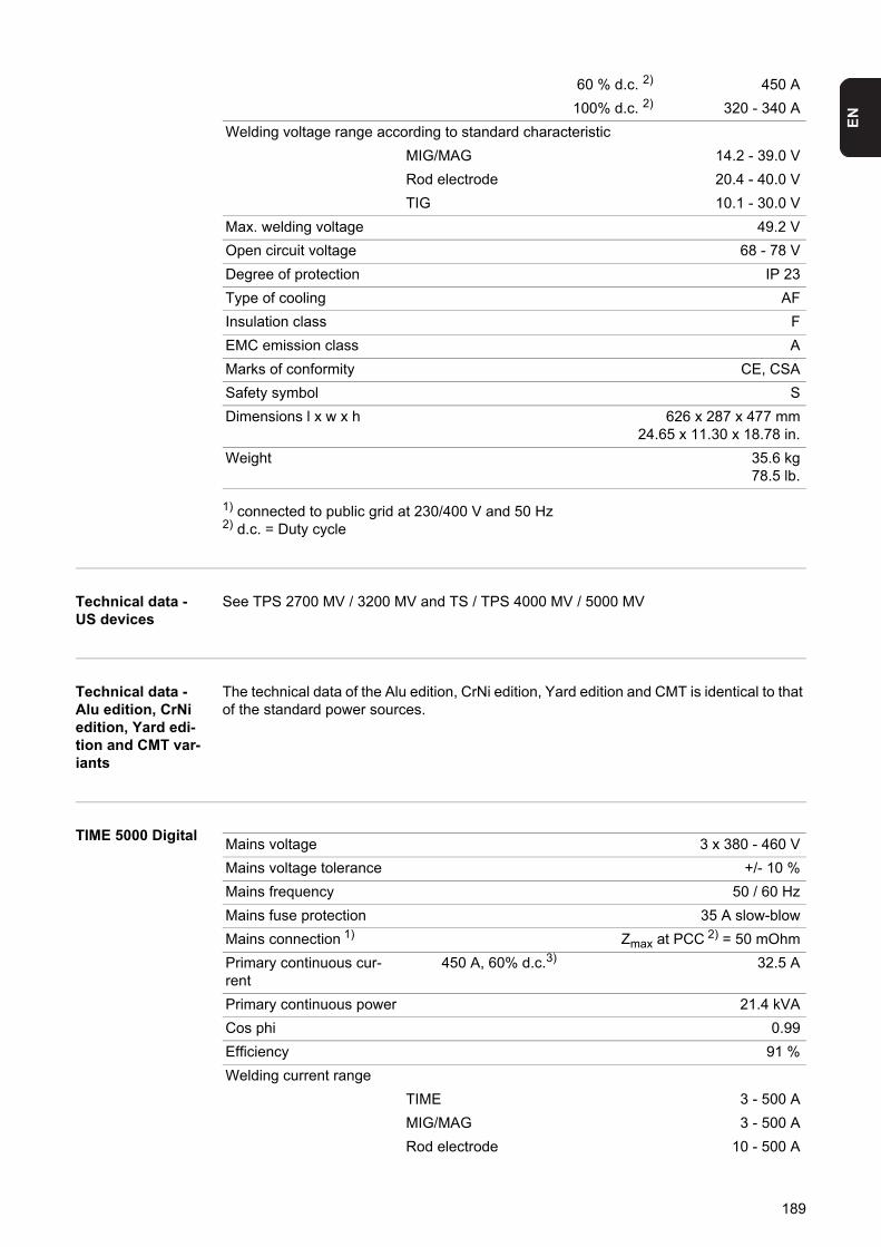
EN
1) connected to public grid at 230/400 V and 50 Hz2) d.c. = Duty cycle
Technical data - US devices
See TPS 2700 MV / 3200 MV and TS / TPS 4000 MV / 5000 MV
Technical data - Alu edition, CrNi edition, Yard edi-tion and CMT var-iants
The technical data of the Alu edition, CrNi edition, Yard edition and CMT is identical to that of the standard power sources.
TIME 5000 Digital
60 % d.c. 2) 450 A
100% d.c. 2) 320 - 340 A
Welding voltage range according to standard characteristic
MIG/MAG 14.2 - 39.0 V
Rod electrode 20.4 - 40.0 V
TIG 10.1 - 30.0 V
Max. welding voltage 49.2 V
Open circuit voltage 68 - 78 V
Degree of protection IP 23
Type of cooling AF
Insulation class F
EMC emission class A
Marks of conformity CE, CSA
Safety symbol S
Dimensions l x w x h 626 x 287 x 477 mm24.65 x 11.30 x 18.78 in.
Weight 35.6 kg78.5 lb.
Mains voltage 3 x 380 - 460 V
Mains voltage tolerance +/- 10 %
Mains frequency 50 / 60 Hz
Mains fuse protection 35 A slow-blow
Mains connection 1) Zmax at PCC 2) = 50 mOhm
Primary continuous cur-rent
450 A, 60% d.c.3) 32.5 A
Primary continuous power 21.4 kVA
Cos phi 0.99
Efficiency 91 %
Welding current range
TIME 3 - 500 A
MIG/MAG 3 - 500 A
Rod electrode 10 - 500 A
189
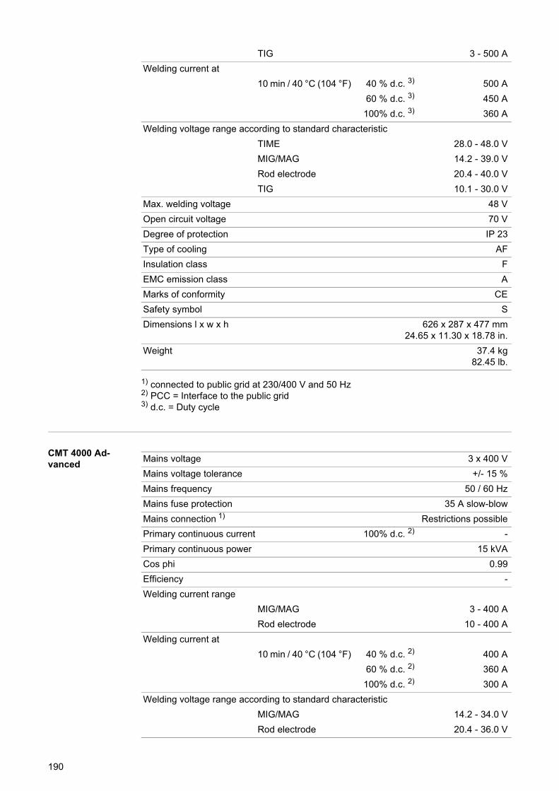
1) connected to public grid at 230/400 V and 50 Hz2) PCC = Interface to the public grid3) d.c. = Duty cycle
CMT 4000 Ad-vanced
TIG 3 - 500 A
Welding current at
10 min / 40 °C (104 °F) 40 % d.c. 3) 500 A
60 % d.c. 3) 450 A
100% d.c. 3) 360 A
Welding voltage range according to standard characteristic
TIME 28.0 - 48.0 V
MIG/MAG 14.2 - 39.0 V
Rod electrode 20.4 - 40.0 V
TIG 10.1 - 30.0 V
Max. welding voltage 48 V
Open circuit voltage 70 V
Degree of protection IP 23
Type of cooling AF
Insulation class F
EMC emission class A
Marks of conformity CE
Safety symbol S
Dimensions l x w x h 626 x 287 x 477 mm24.65 x 11.30 x 18.78 in.
Weight 37.4 kg82.45 lb.
Mains voltage 3 x 400 V
Mains voltage tolerance +/- 15 %
Mains frequency 50 / 60 Hz
Mains fuse protection 35 A slow-blow
Mains connection 1) Restrictions possible
Primary continuous current 100% d.c. 2) -
Primary continuous power 15 kVA
Cos phi 0.99
Efficiency -
Welding current range
MIG/MAG 3 - 400 A
Rod electrode 10 - 400 A
Welding current at
10 min / 40 °C (104 °F) 40 % d.c. 2) 400 A
60 % d.c. 2) 360 A
100% d.c. 2) 300 A
Welding voltage range according to standard characteristic
MIG/MAG 14.2 - 34.0 V
Rod electrode 20.4 - 36.0 V
190
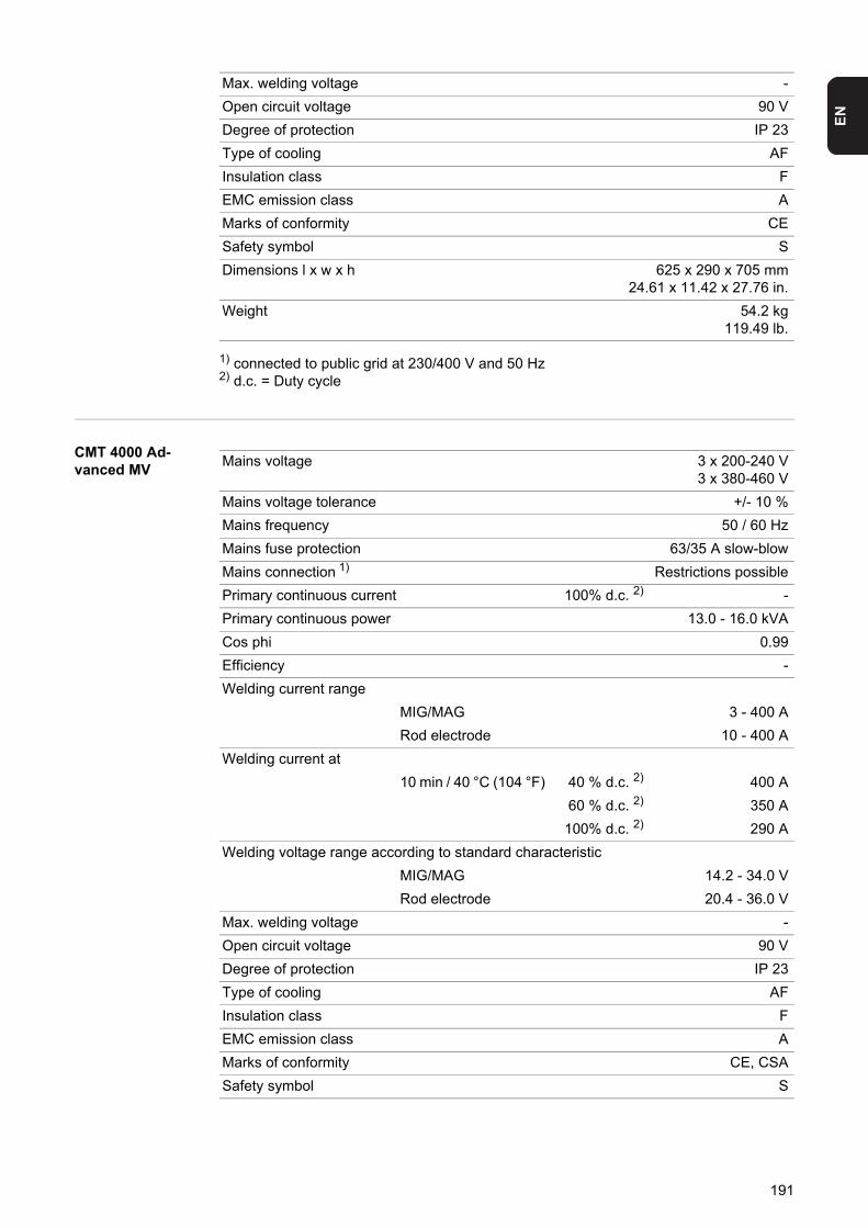
EN
1) connected to public grid at 230/400 V and 50 Hz2) d.c. = Duty cycle
CMT 4000 Ad-vanced MV
Max. welding voltage -
Open circuit voltage 90 V
Degree of protection IP 23
Type of cooling AF
Insulation class F
EMC emission class A
Marks of conformity CE
Safety symbol S
Dimensions l x w x h 625 x 290 x 705 mm24.61 x 11.42 x 27.76 in.
Weight 54.2 kg119.49 lb.
Mains voltage 3 x 200-240 V3 x 380-460 V
Mains voltage tolerance +/- 10 %
Mains frequency 50 / 60 Hz
Mains fuse protection 63/35 A slow-blow
Mains connection 1) Restrictions possible
Primary continuous current 100% d.c. 2) -
Primary continuous power 13.0 - 16.0 kVA
Cos phi 0.99
Efficiency -
Welding current range
MIG/MAG 3 - 400 A
Rod electrode 10 - 400 A
Welding current at
10 min / 40 °C (104 °F) 40 % d.c. 2) 400 A
60 % d.c. 2) 350 A
100% d.c. 2) 290 A
Welding voltage range according to standard characteristic
MIG/MAG 14.2 - 34.0 V
Rod electrode 20.4 - 36.0 V
Max. welding voltage -
Open circuit voltage 90 V
Degree of protection IP 23
Type of cooling AF
Insulation class F
EMC emission class A
Marks of conformity CE, CSA
Safety symbol S
191

1) connected to public grid at 230/400 V and 50 Hz2) d.c. = Duty cycle
Dimensions l x w x h 625 x 290 x 705 mm24.61 x 11.42 x 27.76 in.
Weight 56.0 kg123.46 lb.
192
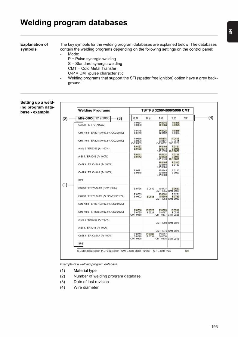
EN
Welding program databases
Explanation of symbols
The key symbols for the welding program databases are explained below. The databases contain the welding programs depending on the following settings on the control panel:- Mode:
P = Pulse synergic weldingS = Standard synergic weldingCMT = Cold Metal TransferC-P = CMT/pulse characteristic
- Welding programs that support the SFi (spatter free ignition) option have a grey back-ground.
Setting up a weld-ing program data-base - example
Example of a welding program database
(1) Material type
(2) Number of welding program database
(3) Date of last revision
(4) Wire diameter
Welding Programs TS/TPS 3200/4000/5000 CMT
M09-0005 12.9.2006 0.8 0.9 1.0 1.2 SP
G3 Si1 / ER 70 (ArCO2)
CrNi 18 8 / ER307 (Ar 97.5%/CO2 2.5%)
CrNi 19 9 / ER308 (Ar 97.5%/CO2 2.5%)
AlMg 5 / ER5356 (Ar 100%)
AlSi 5 / ER4043 (Ar 100%)
CuSi 3 / ER CuSi-A (Ar 100%)
CuAl 9 / ER CuAl-A (Ar 100%)
SP1
G3 Si1 / ER 70-S-3/6 (CO2 100%)
G3 Si1 / ER 70-S-3/6 (Ar 82%/CO2 18%)
CrNi 18 8 / ER307 (Ar 97.5%/CO2 2.5%)
CrNi 19 9 / ER308 (Ar 97.5%/CO2 2.5%)
AlMg 5 / ER5356 (Ar 100%)
AlSi 5 / ER4043 (Ar 100%)
CuSi 3 / ER CuSi-A (Ar 100%)
SP2
P 0074S 0008
P 0346S 1084
P 0378S 0375
P 0148S 0149
P 0421S 0102
P 0345S 0033
P 0076S 0009
C-P 0959
P 0414S 0101
C-P 0882
P 0415S 0011
C-P 0929P 0137S 0138
P 0408S 0014
C-P 1070
P 0191S 0015
C-P 0879P 0141S 0142
P 0131S 0132
C-P 1076
P 0116S 0016
C-P 0881P 0405S 0104
C-P 0884
P 0342S 0153
P 0071S 0018
P 0143S 0103
C-P 0883
P 0113S 0020
S 0736 S 0519 S 0737CMT 1055
S 0687CMT 0986
P 0735S 0602 S 0808
P 0891S 0603
CMT 1053
P 0271S 0783
CMT 0963
P 0766S 0765
CMT 0960
P 0525S 0524
P 0799S 0767
CMT 0877
P 0539S 0538
CMT 0928
CMT 1069 CMT 0875
CMT 1075 CMT 0876P 0219S 0220
CMT 0920
P 0530S 0531
P 0057S 0638
CMT 0878 CMT 0918
S....Standardprogram P....Pulsprogram CMT....Cold Metal Transfer C-P....CMT Puls SFI
(4)(3)
(1)
(2)
193
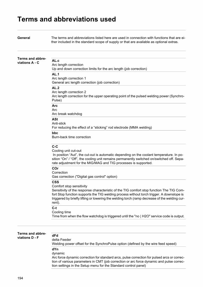
Terms and abbreviations used
General The terms and abbreviations listed here are used in connection with functions that are ei-ther included in the standard scope of supply or that are available as optional extras.
Terms and abbre-viations A - C
Terms and abbre-viations D - F
AL.cArc length correctionUp and down correction limits for the arc length (job correction)
AL.1Arc length correction 1General arc length correction (job correction)
AL.2Arc length correction 2Arc length correction for the upper operating point of the pulsed welding power (Synchro-Pulse)
ArcArcArc break watchdog
AStAnti-stickFor reducing the effect of a “sticking” rod electrode (MMA welding)
bbcBurn-back time correction
C-CCooling unit cut-out In position “Aut”, the cut-out is automatic depending on the coolant temperature. In po-sition “On” / “Off”, the cooling unit remains permanently switched on/switched off. Sepa-rate adjustment for the MIG/MAG and TIG processes is supported.
COrCorrectionGas correction ("Digital gas control" option)
CSSComfort stop sensitivitySensitivity of the response characteristic of the TIG comfort stop function The TIG Com-fort Stop function supports the TIG welding process without torch trigger. A downslope is triggered by briefly lifting or lowering the welding torch (ramp decrease of the welding cur-rent).
C-tCooling timeTime from when the flow watchdog is triggered until the "no | H2O" service code is output.
dFddelta FeederWelding power offset for the SynchroPulse option (defined by the wire feed speed)
dYndynamicArc force dynamic correction for standard arcs, pulse correction for pulsed arcs or correc-tion of various parameters in CMT (job correction or arc force dynamic and pulse correc-tion settings in the Setup menu for the Standard control panel)
194
EN
Terms and abbre-viations G - I
Terms and abbre-viations J - R
ElnElectrode lineCharacteristic selection (MMA welding)
FFrequencyFrequency for SynchroPulse option
FACFactoryReset welding system
FCOFeeder controlWire-feed unit cut-out (wire-end sensor option)
FdcFeeder creepFeeder creep speed
FdiFeeder inchingFeeder inching speed
GASGasflowSet value for shielding gas flow ("Digital gas control" option)
GPoGas post-flow time
GPRGas pre-flow time
GunGun (welding torch)Changing between modes with the JobMaster torch (optional) ... 0 / 1
HCUHot-start current
HtiHot-current time(MMA welding)
I-EI (current) - End Final current
I-SI (current) - StartingStarting current
ItoIgnition time-out
JobJob whose parameters are to be adjusted (job correction)
JSLJob SlopeDefines the time between the job that is currently selected and the next job
195
Terms and abbre-viations S
Terms and abbre-viations T - 2nd
LL (inductivity)Displays welding circuit inductivity
PPower-correctionWelding power correction (defined by the wire feed speed, job correction function)
P-CPower-ControlFor defining the Master or Slave power sources when two power sources are operated in parallel
PcHPower correction HighCorrection boundary (high) for the welding power (job correction)
PcLPower correction LowCorrection boundary (low) for the welding power (job correction)
PPUPush-pull unit
rr (resistance)Determine welding circuit resistance
SEtSettingCountry-specific setting (Standard / USA)
SLSlope
SPtSpot welding time
StcWire-Stick-ControlDetection of a sticking wire end
S2tSpecial 2-step (US control panel only)For selecting jobs and groups by pressing the torch trigger
S4tSpecial 4-step (Gun-Trigger option)Switch between jobs using torch trigger while "Special 4-step" mode symbol is displayed on JobMaster torch
t-CTwin ControlFor defining the leading or trailing power sources in the TimeTwin Digital process
t-Etime - End currentFinal current duration
196

EN
t-Stime - Starting currentStarting current duration
triTriggerSubsequent correction of the mode
UcoU (Voltage) cut-offWelding voltage limitation during MMA welding Makes it possible to stop the welding process by slightly raising the rod electrode.
2ndSecond level of Setup menu
197

198

Spare parts list
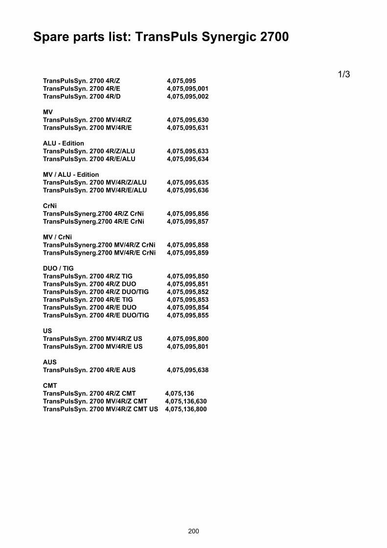
Spare parts list: TransPuls Synergic 2700
200
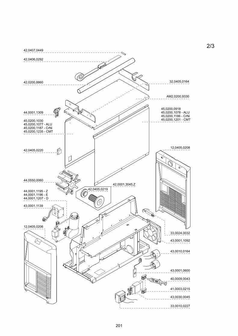
201
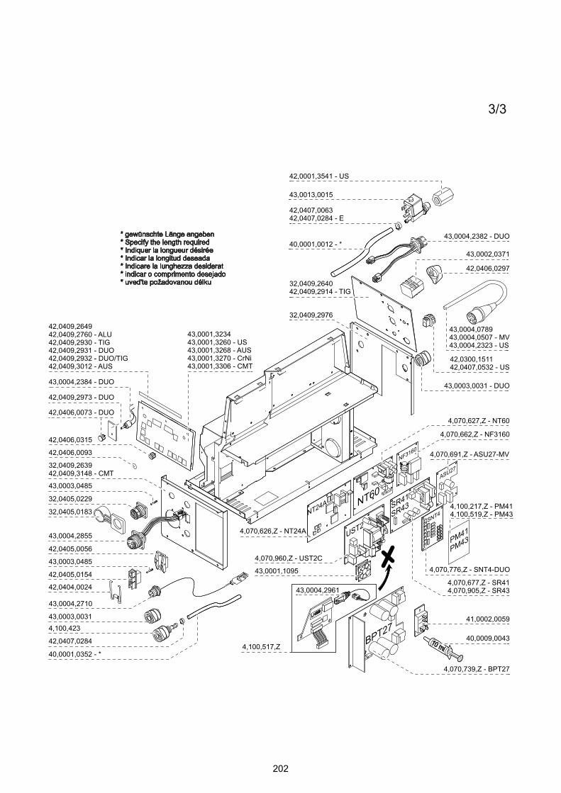
202
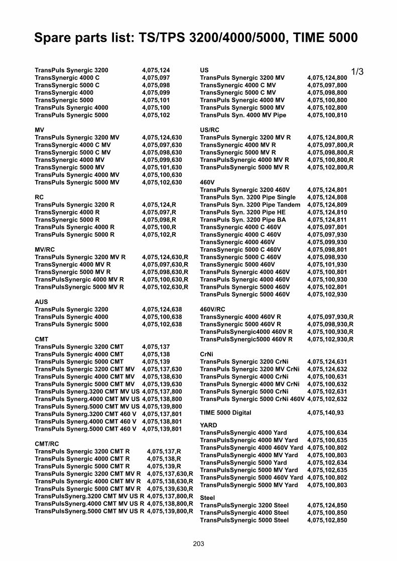
Spare parts list: TS/TPS 3200/4000/5000, TIME 5000
203
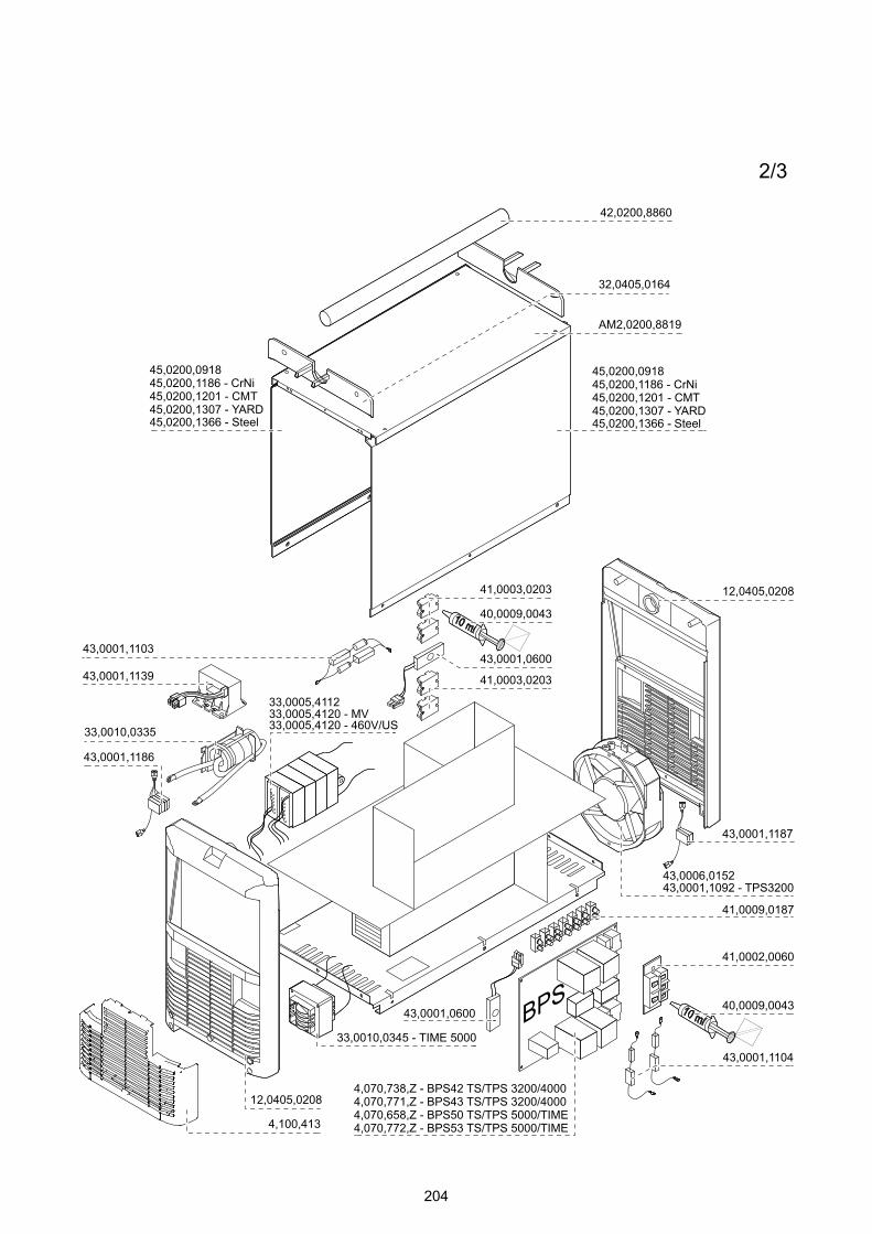
204
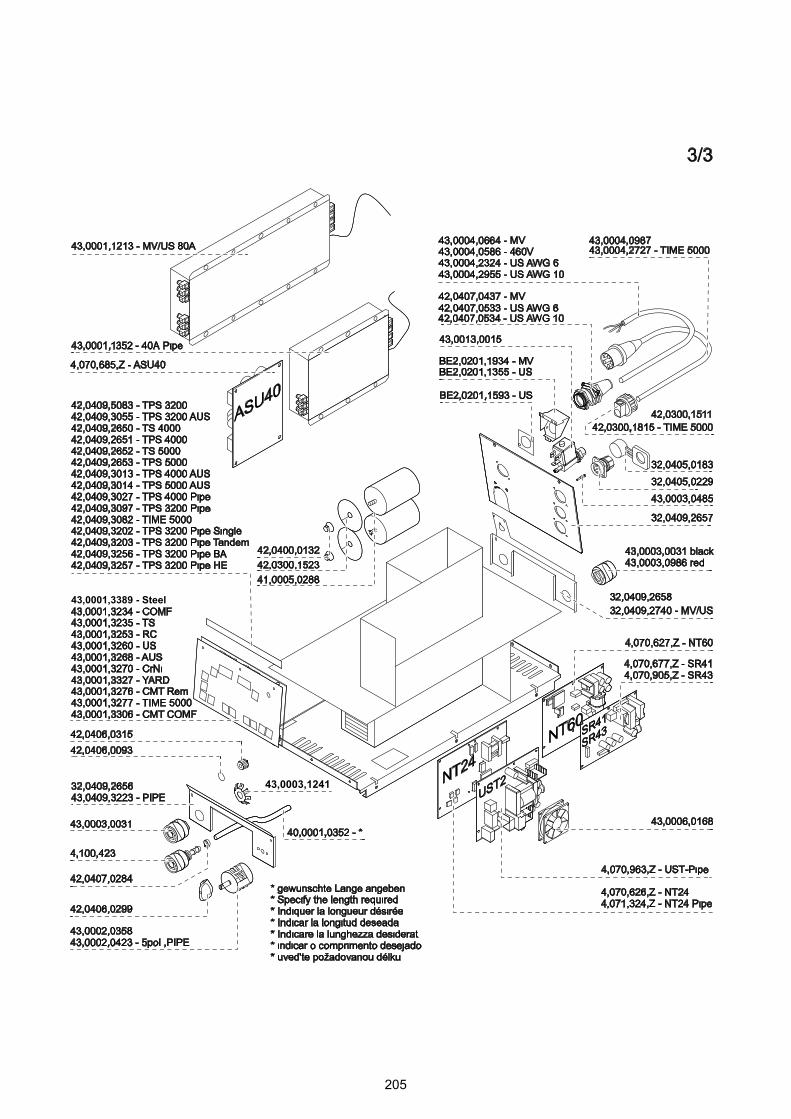
205
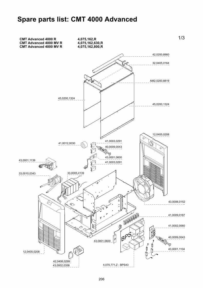
Spare parts list: CMT 4000 Advanced
206
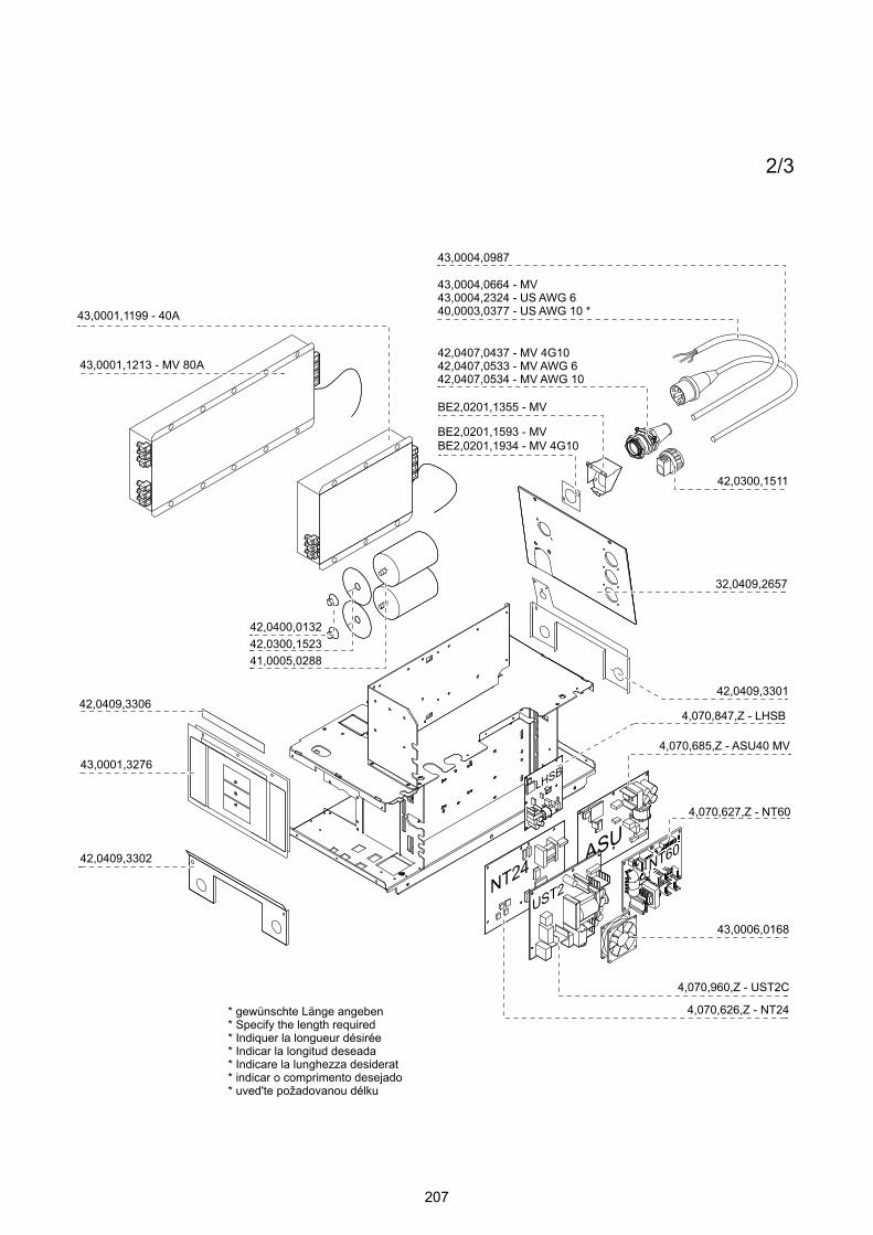
207
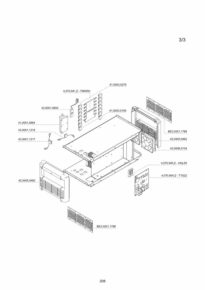
208

Maahantuonti ja myynti:
Pronius Oy
Keisarinviitta 20 B33960 Pirkkala
+358 (0)44 200 [email protected]


![Optical Measurement of the Connection State in Laser Brazing · PDF fileihg e\ d transpuls synergic 4000 zluh ihhghu iurp fronius 'xulqj wkh eud]lqj surfhvv wkh irfxvlqj rswlfv duh](https://static.fdocuments.us/doc/165x107/5aae7f8b7f8b9a5d0a8c3008/optical-measurement-of-the-connection-state-in-laser-brazing-e-d-transpuls-synergic.jpg)

